
REF542plus OM 1MRS755869 ENa 1..104 - ABB Group Part 3, Installation and Commission 1 VTA100004...
104
REF542plus Multifunction Protection and Switchgear Control Unit Operator's manual
Transcript of REF542plus OM 1MRS755869 ENa 1..104 - ABB Group Part 3, Installation and Commission 1 VTA100004...

REF542plus
Multifunction Protection and Switchgear Control Unit
Operator's manual

3
Contents
1. Introduction.... ................................................................ ..... 71.1. This manual.................................................................... ...... 71.2. Use of symbols.... .......................................................... ...... 71.3. Intended audience.......................................................... ...... 81.4. Product documentation.... .............................................. ...... 81.5. Revision history.... .......................................................... ...... 8
2. Safety information.... .......................................................... 9
3. HMI features.... .................................................................. 113.1. Control area.................................................................... .... 113.2. Info and Menu area........................................................ .... 133.3. REF542plus status information area.... ......................... .... 15
4. Behavior at power up.................................................... ... 17
5. Control modes.... .............................................................. 195.1. Available control modes................................................. .... 195.2. Changing the control modes.......................................... .... 19
6. Operating the primary objects.... .................................... 21
7. Viewing and resetting alarms.... ..................................... 237.1. Viewing alarms.... ........................................................... .... 237.2. Resetting alarms.... ........................................................ .... 23
8. Viewing measurements.................................................... 25
9. Viewing events.... .............................................................. 27
10. Viewing and changing the protection settings.... ........ 2910.1. Viewing the protection settings...................................... .... 2910.2. Changing the protection settings.... ............................... .... 29
10.2.1. Changing the protection key mode................. .... 2910.2.2. Changing the protection parameters.... .......... .... 3010.2.3. Changing the active parameter set.... ............ .... 3210.2.4. Viewing and changing control parameters.... . .... 33
11. Setting the time and date.... ............................................ 35
12. Command page.............................................................. ... 37
13. REF542plus commissioning mode.... ............................ 3913.1. Binary input commissioning page.................................. .... 4013.2. Binary output commissioning page.... ........................... .... 4113.3. Analog input commissioning page................................. .... 4213.4. Analog output 4- 20 mA commissioning page.............. .... 4413.5. Analog input 4-20 mA commissioning page.... ............. .... 4613.6. Optical inputs commissioning page............................... .... 47
Multifunction Protection and Switchgear ControlUnit
Operator's manual
REF542plus1MRS755869
Issued: 01.11.2002Version: A/28.02.2006

13.7. Optical output commissioning page.... .......................... .... 47
14. Connection to PC.... ......................................................... 4914.1. Optical to RS232 converter cable.... ............................. .... 4914.2. Downloading a configuration.... ..................................... .... 49
14.2.1. Serial port settings.... ...................................... .... 5014.3. Uploading the configuration.... ....................................... .... 5214.4. Uploading other information........................................... .... 53
15. Troubleshooting.... ......................................................... ... 5515.1. Error messages.... .......................................................... .... 5515.2. Clearing the configuration inside the unit...................... .... 6015.3. Primary objects incorrect visualization.... ...................... .... 60
16. Terminology.... ................................................................ ... 63
17. Abbreviations.... ................................................................ 65
18. Appendix A: Connection diagrams.... ............................ 6718.1. Analog Inputs.... ............................................................. .... 6918.2. Binary inputs and outputs.... .......................................... .... 72
18.2.1. Static.... ............................................................ .... 7218.2.2. Electromechanical.... ....................................... .... 73
18.2.2.1. BIO3.... ............................................ .... 7318.3. Other connections.... ...................................................... .... 75
18.3.1. Analog outputs 0/4-20 mA.... .......................... .... 7518.3.2. Analog inputs 4-20 mA.... ............................... .... 7518.3.3. Communication module................................... .... 7618.3.4. Power supply.... ............................................... .... 7618.3.5. Time synchronization.... .................................. .... 7718.3.6. HMI.... .............................................................. .... 77
19. Appendix B: Menu structure.... ....................................... 7919.1. Reset page.... ................................................................. .... 8019.2. Service page.... .............................................................. .... 8219.3. Test page.... .................................................................... .... 98
19.3.1. Test HMI........................................................... .... 9819.3.2. Test primary object.... ...................................... .... 99
20. Appendix C: Tripping time indication.... ..................... . 101
4
REF542plusMultifunction Protection and Switchgear ControlUnit
Operator's manual
1MRS755869

5
CopyrightsThe information in this document is subject to change without notice andshould not be construed as a commitment by ABB Oy. ABB Oy assumes noresponsibility for any errors that may appear in this document.
In no event shall ABB Oy be liable for direct, indirect, special, incidental orconsequential damages of any nature or kind arising from the use of thisdocument, nor shall ABB Oy be liable for incidental or consequentialdamages arising from use of any software or hardware described in thisdocument.
This document and parts thereof must not be reproduced or copied withoutwritten permission from ABB Oy, and the contents thereof must not beimparted to a third party nor used for any unauthorized purpose.
The software or hardware described in this document is furnished under alicense and may be used, copied, or disclosed only in accordance with theterms of such license.
Copyright © 2006 ABB Oy
All rights reserved.
Trademarks
ABB is a registered trademark of ABB Group. All other brand or productnames mentioned in this document may be trademarks or registeredtrademarks of their respective holders.
Guarantee
Please inquire about the terms of guarantee from your nearest ABBrepresentative.
1MRS755869
Multifunction Protection and Switchgear ControlUnit
Operator's manual
REF542plus

6
7
1. Introduction
1.1. This manual
Before attempting any operation with REF542plus, read this manual carefullyfirst.
This manual describes how to use the interface of REF542plus (LD HMI,Local Detached Human Machine Interface). Note that HMI views andpictures are to be considered exemplary.
Do not make any changes to the REF542plus configurationunless you are authorized to do it and familiar with REF542plusand its Operating Tool. This might result in malfunction and lossof warranty.
1.2. Use of symbols
This publication includes the following icons that point out safety-relatedconditions or other important information:
The electrical warning icon indicates the presence of a hazardwhich could result in electrical shock.
The warning icon indicates the presence of a hazard which couldresult in personal injury.
The caution icon indicates important information or warningrelated to the concept discussed in the text. It might indicate thepresence of a hazard which could result in corruption of softwareor damage to equipment or property.
The information icon alerts the reader to relevant facts andconditions.
It should be understood that operation of damaged equipment could, undercertain operational conditions, result in degraded process performanceleading to information or property loss. Therefore, comply fully with allnotices.
1MRS755869
Multifunction Protection and Switchgear ControlUnit
Operator's manual
REF542plus

1.3. Intended audience
This manual is intended for operators, supervisors and administrators tosupport normal use of the product.
1.4. Product documentation
Name of the Manual Document ID
Application Notes 1MRS755870
CAN Manual 1VTA100189-Rev 1, en
Configuration Manual 1MRS755871
iButton Programmer User Manual 1MRS755863
Manual Part 3, Installation and Commission 1 VTA100004
Manual Part 4, Communication 1VTA100005
Motor Protection with ATEX Certification, Manual 1MRS755862
Operator’s Manual 1MRS755869
Protection Manual 1MRS755860
Technical Catalogue 1MRS755859
Technical Reference Modbus RTU 1MRS755868
Web Manual, Installation 1MRS755865
Web Manual, Operation 1MRS755864
1.5. Revision history
Version Date History
1VTA100172-Rev 1, en 01.11.2002 First release
1VTA100172-Rev 2, en 22.10.2003 Updated to version 4D02
1VTA100172-Rev 3, en 03.05.2004 Updated
1VTA100172-Rev 4, en 04.04.2005 Updated
A 28.02..2006 Document updated* language* layout
Applicability
This manual is applicable to REF542plus Release 2.0, software versionV4D02.
8
REF542plusMultifunction Protection and Switchgear ControlUnit
Operator's manual
1MRS755869

9
2. Safety information
Dangerous voltages can occur on the connectors, even thoughthe auxiliary voltage has been disconnected.
Non-observance can result in death, personal injury orsubstantial property damage.
Only a competent electrician is allowed to carry out the electricalinstallation.
National and local electrical safety regulations must always befollowed.
The frame of the device has to be carefully earthed.
The device contains components which are sensitive toelectrostatic discharge. Unnecessary touching of electroniccomponents must therefore be avoided.
1MRS755869
Multifunction Protection and Switchgear ControlUnit
Operator's manual
REF542plus

10

11
3. HMI featuresThe REF542plus HMI is shown in Fig. 3.-1. The HMI features a backilluminated LCD, 8 push buttons, several LEDs and an electronic key sensor.The language of the display, when available, can be selected via theOperating Tool. The default language is English.
A051327
Fig. 3.-1 REF542plus HMI
The LCD in the SLD view provides a graphical representation of the primaryobjects controlled or monitored by REF542plus in the switchgear. The righthalf of the LCD is for plain text visualization such as measurements andprotection events. The contrast level is automatically controlled for anoptimum reading, it can also be adjusted as wanted.
The HMI panel is organized in three main areas.
3.1. Control area
The left side of the HMI panel is for primary objects control. The commandbuttons and the information related to the switchgear control are placed onthis area
1MRS755869
Multifunction Protection and Switchgear ControlUnit
Operator's manual
REF542plus

A051328
Fig. 3.1.-1 HMI control area
1 E-Key sensor
This section of the LCD display shows the Single Line Diagram (SLD) of thecontrolled panel and the measurement bars. Text can be added in this sectionto improve the understanding of SLD.
* Command buttons
The Primary Object Control can be performed with the following pushbuttons to allow operating the primary objects if configured as “selectable”.The command push buttons for local operation of the switching devices are:
Open: to open the selected object.
Close: to close the selected object.
Select: to select the object. The selected object appears highlighted.
CB Fast Opening: to allow opening of the circuit breaker independentlyfrom the selected control mode. When pressed simultaneously with thenormal open button, this button allows opening the circuit breakerindependently from the selected control mode. This feature must beenabled in the unit with the Operating Tool.
* E-Keys Sensor: this is the sensor for the electronic keys. The sensorautomatically detects which key has been inserted. The two keys areusually labelled “Protect” and “Control” to distinguish them.
* Protection key: is specialized to the protection environment allowingchanging of parameters and other functions related to the protection.
* Control Key: this is dedicated to the control modes. It allows changing theoperating mode of REF542plus. The different operating modes disciplinethe access to the primary objects by the different REF542plus interfaces(HMI and SCADA). When required, a Super User key to access both
12
REF542plusMultifunction Protection and Switchgear ControlUnit
Operator's manual
1MRS755869

13
modes can be provided. The Super User key is also needed to access thecommissioning test mode. The password codes stored in the key can becustomized in each REF542plus for access restriction purposes.
* SLD view: this is the graphical part of the LCD. This part shows the singleline diagram of the switchgear. The status of the primary objects isdynamically updated after every operation. If for example the circuitbreaker has been opened, its representation will reflect it.
3.2. Info and Menu area
The right side of the HMI LCD is for information and menu browsing. Thebuttons to navigate through the menus and to change items are placed on thisarea.
A051333
Fig. 3.2.-1 Info and Menu area
* Menu Navigation: these push buttons allow navigation trough theREF542plus menus.
Pressing this button, the unit goes back to the former menu.
The up direction push button.
The down direction push button.
The enter push button to enter into the selected menu or to selectthe highlighted submenu.
The following menus are available in the main window:
* Commands: this menu shows the configured FUPLA commands.* E-Key status: to display and change the unit modes with the electronic
keys.* Alarms: it displays the indication LED’s status.
1MRS755869
Multifunction Protection and Switchgear ControlUnit
Operator's manual
REF542plus
* Measurements: it displays the available measurements.* Resets: to acknowledge alarms and other quantities.* Events: to display protection starts and trips events.* Protection: it displays the protection functions installed in the unit, and
allows displaying and changing their settings.* Control: it displays the control functions list installed in the unit and
allows displaying and changing their settings.* Service: relevant information on the HW and SW configurations and basic
setting of REF542plus.* Tests: to access the test mode for the HMI and the primary objects.
Access to a few submenus is allowed only in some modes.
* LED bars: The three LED bars are available to show the most relevantmeasurements acquired by REF542plus for a quick inspection of theswitchgear load situation. The three bars are marked M1, M2, and M3.Each bar is composed of twelve LEDs, ten green and two red ones. Theten green LEDs are normally dedicated to display between 0% and 100%of the nominal value of the configured measurement. Each LEDcorresponding then to 10% of the nominal value. The two red LEDsindicate an overload condition of 20%. The measurements displayed bythe bars are set with the Operating Tool.
* Indication LEDs: 8 freely programmable, three-color LEDs are availablefor indications. There are 4 pages of these LEDs. As a result, a total of 32indication options can be programmed for events and status regardingprotection, control, monitoring, binary inputs and so on. The assignmentof the LED to a specific condition is done with the Operating Tool.
* Optical interface: This is the optical serial interface port to connectREF542plus to a personal computer. By using the appropriate cable andthe Operating Tool, the following actions are possible:* Download a configuration into the unit.* Upload the current configuration from the unit.* After a fault, upload the fault recorder data. This is possible only if the
fault recorder has been previously enabled with the Operating Tool.
Upload other information (measurements, binary inputs status, binary outputstatus).
Do not make any changes to the REF542plus configurationunless you are familiar with REF542plus and the OperatingTool. This might result in malfunction and loss of warranty.
14
REF542plusMultifunction Protection and Switchgear ControlUnit
Operator's manual
1MRS755869

15
3.3. REF542plus status information area
A051338
Fig. 3.3.-1 Status Information area
1 Unit status2 Network Communication status3 Alarm4 Interlocking Error
The HMI shows the following status information:
* Ready. This green LED is turned on when the unit is in the operationalstate. The LED is switched off when the auxiliary power is not present orwhen the unit is not operational (FUPLA is not running).
* Network Communication. This LED is meaningful only when theREF542plus is equipped with a communication module. When acommunication module is detected the LED turns on to green. If themodule is not detected or fails, the LED turns red. When a Modbuscommunication module is installed, the LED becomes orange if thecommunication error rate increases. It becomes red when thecommunication error rate prevents good communication. The LEDcomes back to green when no communication errors occur or byresetting the module status registers (see the Modbus technical reference).When there is no communication module, the LED is always switched off.* Alarm: this LED turns to red when the user defined alarms become
true. Several arbitrary alarm conditions can be defined and configuredwith the Operating Tool. Alarm conditions could be the trip of aprotection function, loss of SF6 in the circuit breaker and so on. Whenthis LED is on, it is not possible to close the circuit breaker or todownload a new configuration. The alarm must be acknowledged first.
* Interlocking Error: this LED is usually green. It turns temporarily tored when the user attempts an operation that would violate theprogrammed interlocking conditions; for example switching adisconnector with the circuit breaker in closed position.
1MRS755869
Multifunction Protection and Switchgear ControlUnit
Operator's manual
REF542plus

16
17
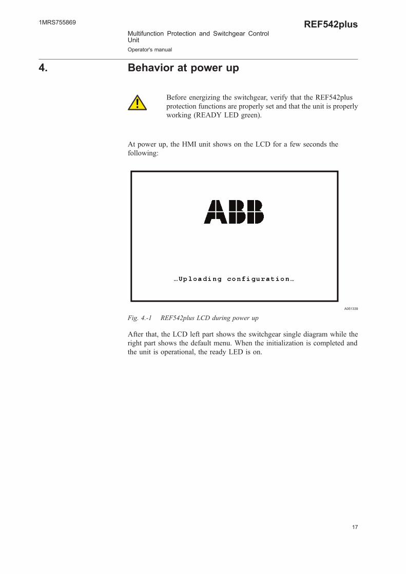
4. Behavior at power up
Before energizing the switchgear, verify that the REF542plusprotection functions are properly set and that the unit is properlyworking (READY LED green).
At power up, the HMI unit shows on the LCD for a few seconds thefollowing:
A051339
Fig. 4.-1 REF542plus LCD during power up
After that, the LCD left part shows the switchgear single diagram while theright part shows the default menu. When the initialization is completed andthe unit is operational, the ready LED is on.
1MRS755869
Multifunction Protection and Switchgear ControlUnit
Operator's manual
REF542plus

18

19
5. Control modes
5.1. Available control modes
Local Control
It is possible to control the circuit breaker and other primary objects from theHMI using the object control buttons. Open and close operations are possibleonly if the interlocking logic programmed into the unit allow them. Remotecontrol from the SCADA is inhibited. Uploading and downloading theconfiguration via the optical interface is possible.
Remote Control
The control of the circuit breaker and other primary objects from the HMI isinhibited. The control is possible only remotely. Uploading and downloadingthe configuration via the optical interface is possible.
No Control
It is not possible to control the circuit breaker and other primary objects bothfrom the HMI and remotely. Any kind of operation apart from the protectiontrip is inhibited. Uploading and downloading the configuration via the opticalinterface is possible.
Local and Remote Control
Both the local control and remote control from HMI are possible. Uploadingand downloading the configuration via the optical interface is possible.
The selection of this control mode requires caution, becauseoperations are allowed both from the HMI and remotely.
5.2. Changing the control modes
The next figure shows how to change the control mode. At first the menu E-Key must be selected. Then the control key must be placed in the electronickey sensor.
Select then the desired control mode by using UP and DOWN until itis highlighted. Confirm the selection by pressing ENTER . After pressingENTER , the E-key status menu will appear again. Verify that the requiredcontrol mode has been properly set in the unit looking in the lower left cornerof the HMI. A text string there indicates the currently selected control andprotection mode.
1MRS755869
Multifunction Protection and Switchgear ControlUnit
Operator's manual
REF542plus

A051340
Fig. 5.2.-1 Changing the control mode by using the control key
20
REF542plusMultifunction Protection and Switchgear ControlUnit
Operator's manual
1MRS755869

21
6. Operating the primary objectsThe primary objects can be operated from the HMI when the selected controlmode is local or local and remote. The Object control push buttons allowoperating the primary objects.
Press to step through the available objects until the desired object isselected (it will appear highlighted in the SLD). The object remainshighlighted until the open or close push button is pressed or the time-out haselapsed.
Press to open the selected object.
Press to close the selected object.
Only primary objects controlled directly by REF542plus can beselected. For example, REF542plus will show the correctposition of a manual disconnect switch after an operation, but itwill not be possible to select it.
1MRS755869
Multifunction Protection and Switchgear ControlUnit
Operator's manual
REF542plus

22
23
7. Viewing and resetting alarms
7.1. Viewing alarms
The presence of an alarm, when latched, is indicated by the alarm LED turnedon or by one of the 8 x 4 pages user programmable LED’s turned on to red.The conditions or the events that generate an alarm are defined andprogrammed with the Operating Tool.
When an alarm is active, the corresponding LED is turned on to red. Selectthe alarm menu with the navigation buttons. Then, this menu displays the textassociated to the alarm condition. The displayed text is defined with theOperating Tool.
There are four pages of alarms and each page reports eight alarms at most.Use the navigation button to browse through the pages.
A051341
Fig. 7.1.-1 Alarm visualization
7.2. Resetting alarms
At first, the reset menu must be selected. Select the reset menu with thenavigation buttons. Highlight the reset alarm line in the menu and then pressENTER .
1MRS755869
Multifunction Protection and Switchgear ControlUnit
Operator's manual
REF542plus

Some alarms might not be reset before the cause that generated it has beenremoved. For example, an alarm due to an error in the tripping circuit (coilsupervision) cannot be reset before the tripping coil is replaced. Whereas analarm generated by a trip of a protection function is normally reset with thisprocedure.
A051342
Fig. 7.2.-1 Resetting alarms
24
REF542plusMultifunction Protection and Switchgear ControlUnit
Operator's manual
1MRS755869

25
8. Viewing measurementsREF542plus offers complete measurements set to the user. To view themeasurements, select the measurement menu with the navigation button. Usethe UP and DOWN buttons to browse the measurement pages.
The available measurements depend upon the unit configuration. In themaximum configuration, the following measurements are displayed:
* IL1, IL2, IL3, in A; line currents, measured values* U1E, U2E, U3E, in kV; phase to earth voltages, measured values* UL12, UL23, UL31, in kV; phase-to-phase voltages, computed values.1)
* IL1 mean, IL2 mean, IL3 mean, in A; mean currents in the observationperiod, computed values
* IL1 max, IL2 max, IL3 max, in A; maximum peak currents in theobservation period, computed values
* Frequency, in Hz; measured values* Active power, in kW; reactive power in kVAr, apparent power in kVA,
computed values* Power factor, computed value* Active energy in MWh, reactive energy in Mvarh; computed values* Operating hours, in hours. This is the total working hours of the unit* Switch cycle, number the circuit breaker close-open cycles* Added switched current, in kA; sum of the interrupted currents by the
circuit breaker* THD (total harmonic distortion)
The observation period is set with the Operating Tool. It can befrom 0 minutes up to 30 minutes. If the observation period is setto 0, the corresponding measurements are disabled.
The refresh time for the displayed measurements is about half second.
1MRS755869
Multifunction Protection and Switchgear ControlUnit
Operator's manual
REF542plus
1) REF542plus can also use phase-to-phase voltage transformers. Whenused, phase-to-phase voltages are measured and phase to earth voltagesare computed.

A051343
Fig. 8.-1 Measurements visualization
The available measurements depend upon the analogue inputmodule type and the unit configuration.
26
REF542plusMultifunction Protection and Switchgear ControlUnit
Operator's manual
1MRS755869

27
9. Viewing eventsREF542plus records the last 30 protection events (start, trips, block andother). This internal memory is managed as a circular buffer, for example the31st event overwrites the 1st oldest one. In case of a power loss, events arekept because they are stored in the non-volatile memory.
For each event, the following information is recorded: involved protectionfunction, event type, relevant measurement (current, voltage, frequency), dateand time (up to milliseconds). Events are displayed using the full screen; thesingle line diagram is thus not visible.
A051344
Fig. 9.-1 Events display
To display the protection events, select the Start/Trip menu with thenavigation buttons. Use UP and DOWN to browse through theevents.
1MRS755869
Multifunction Protection and Switchgear ControlUnit
Operator's manual
REF542plus

28

29
10. Viewing and changing the protection settings
10.1. Viewing the protection settings
The protection functions currently installed in the unit can be seen in themenu protection functions. Select the menu protection functions with thenavigation push buttons.
A051345
Fig. 10.1.-1 Viewing the installed protection functions
Use UP and DOWN to highlight the desired protection function andpress ENTER . Then, the protection parameters will be displayed in oneor more pages.
10.2. Changing the protection settings
10.2.1. Changing the protection key mode
Two different modes are available for the protection functions:
* Set: It is possible both to visualize and to change the protection settings.* Operational: It is possible to visualize the protection settings but it is not
possible to modify them.
In both modes, the protection functions are active.
In the operational mode, parameterization of the protection functions is alsopossible by a SCADAwhen present. In the set mode, parameterization from aSCADA is inhibited.
1MRS755869
Multifunction Protection and Switchgear ControlUnit
Operator's manual
REF542plus

The procedure to change the protection mode is identical to changing thecontrol mode. At first, the menu E-Key must be selected. Then the protectionkey must be placed in the electronic key sensor. Select then the requiredprotection mode by using UP and DOWN until it is highlighted.Confirm the selection by pressing ENTER . After having pressed ENTER
push button, the E-key status menu will appear again. Verify that therequired protection mode has been properly set in the unit, looking in theHMI lower left corner.
A051346
Fig. 10.2.1.-1 Changing the protection mode by using the protection key
10.2.2. Changing the protection parameters
Select the menu protection functions with the navigation push buttons andhighlight the desired protection function. Press ENTER to select it. PressENTER again and the cursor will automatically go to the first parameter.Use Up or Down buttons to modify the parameter as wished. Aftercompleted, press ENTER and use Up and Down button to selectthe next parameter to change.
Repeat the procedure for all the parameters that need to be modified. Thenpress to go back to the list of currently installed protection functions.Repeat the procedure for every protection function that needs to have thesetting modified.
30
REF542plusMultifunction Protection and Switchgear ControlUnit
Operator's manual
1MRS755869
31
A051347
Fig. 10.2.2.-1 Changing protection parameters
Press again to leave the protection functions menu. The unit will then askwhat to do with the changes:
The following screen will appear:
A051348
Fig. 10.2.2.-2 Unit right screen after protection parameters modification
1MRS755869
Multifunction Protection and Switchgear ControlUnit
Operator's manual
REF542plus

Select the desired choice with Up or Down and then press ENTERto confirm it. The meaning of the choices is as follows:
Store permanently: The new parameters are stored in the unit internalmemory. They will be used immediately and for all the next starts.
Save temporarily: The new parameters are used immediately but are notsaved in the unit internal memory. Next starts will use the old parameters.
Discard changes: The new parameters are discarded. There are no effects.
Do not switch off the Base Unit power supply during parameterstoring. The whole unit configuration might be corrupted and anew configuration download might be necessary.
10.2.3. Changing the active parameter set
Most of the protection functions have two different parameter sets to copewith different plant situations. This menu allows seeing and changing theactive parameter set.
Changing the active parameter set is possible only with the protection in theset mode.
Select the active set page menu and press ENTER to make the change.
A051349
Fig. 10.2.3.-1 Changing the protection active parameter set
32
REF542plusMultifunction Protection and Switchgear ControlUnit
Operator's manual
1MRS755869

33
10.2.4. Viewing and changing control parameters
Select the Control menu with the navigation push buttons and highlight thedesired control function. Press ENTER to select it. Press again andthe cursor will automatically go to the first control parameter. Use the Upor Down button to modify the parameter as wished. After themodification, press and use Up Down to select the nextparameter to change.
Repeat the procedure for all the parameters that need to be modified. Thenpress to go back to the list of currently installed protection functions.Repeat the procedure for every control function that needs to have the settingmodified.
A051350
Fig. 10.2.4.-1 Control parameters page
1MRS755869
Multifunction Protection and Switchgear ControlUnit
Operator's manual
REF542plus

34

35
11. Setting the time and dateDuring commissioning, the internal time and date of the unit should be set tothe current values. There are a few differences according to the unitconfiguration.
Standalone unit: The internal time of the unit has to be set to the currentvalue. To do it, select the service menu and then the MC time submenu withthe navigation buttons.
A051351
Fig. 11.-1 Setting the time
The time is edited by using UP , DOWN and then ENTER toconfirm. The complete date and time must be inserted: year, month, day, hour,minutes and seconds.
Unit connected to a master clock: When the unit is connected to a masterclock (typically a clock which receives its signal from a GPS), only the yearcan be set. The remaining part of the date and time is received from themaster clock.
Unit connected to a SCADA system: Usually, the SCADA transmits to theunit the date and time according to the used protocol services. There are somedifferences depending upon the used protocol. IEC 60870-5-103 protocol:The IEC 60870-5-103 module is the time master. Setting the time and datefrom the HMI is inhibited. LON LAG 1.4 protocol: The LON module is thetime master. Setting the time and date from the HMI is inhibited. SPA bus andModbus protocols: usually, the SCADA sets the date and time, neverthelesssetting the time and date from the HMI is allowed.
1MRS755869
Multifunction Protection and Switchgear ControlUnit
Operator's manual
REF542plus

36
37
12. Command pageFrom this page, it is possible to access the HMI command objects configuredin the application software of REF542plus. For more information on theseobjects, refer to Operating Tool user manual.
A051352
Fig. 12.-1 Command page
By selecting the desired command and pressing ENTER the command isexecuted.
1MRS755869
Multifunction Protection and Switchgear ControlUnit
Operator's manual
REF542plus

38
39
13. REF542plus commissioning modeThe commissioning test mode allows accessing all the digital and analogueinputs and outputs of REF542plus. This mode is independent of theREF542plus application. This working mode has been designed to makeeasier the wiring verification.
The super user key is required to enter this mode.
Entering this mode STOPS the execution of the protection andcontrol functions. The application software is not running.However, it is not deleted from the permanent memory of theunit. The commissioning test mode should be entered when theswitchgear is de-energized and in a safe state.
To switch on this mode the following actions have to be performed insequence.
* Switch off the REF542plus Base Unit.* Place the super user key on the e-key sensor and keep it contacted.* Switch on the Base Unit.
When the Base Unit starts the e-key is detected. The commissioning mode isentered. Verify this reading on the start-up status line “COMMISSIONINGMODE”. When this text is visible, the e-key can be unplugged from the e-keysensor.
This mode allows driving directly the binary outputs of the BaseUnit. If they are connected to primary objects, operations arethus possible. The interlocking functions are disabled. Beforeaccessing this mode, put the switchgear in safe conditions.
When entering the commissioning mode, the following screen is displayed.
1MRS755869
Multifunction Protection and Switchgear ControlUnit
Operator's manual
REF542plus

A051353
Fig. 13.-1 Commissioning mode display
13.1. Binary input commissioning page
This page displays the current status of the binary input channels on thebinary IO modules. There are 14 binary inputs per module available. For thebinary inputs numbering see Section 18.2. Binary inputs and outputs.
Line description: “Channel descriptor” “Channel number “: “Values”
Channel descriptor: Binary input
Channel number: x-yy. Where x addresses the binary IO slot, yy is the binaryinput number. 1 means X20 slot and so forth.
Values: 0 → input is not active. Applied voltage is below theactivation threshold.1 → input is active. Applied voltage is above the activationthreshold.
40
REF542plusMultifunction Protection and Switchgear ControlUnit
Operator's manual
1MRS755869

41
A051354
Fig. 13.1.-1 Binary inputs commissioning page
13.2. Binary output commissioning page
On this page, it is possible to force the status of the binary outputs. All theoutputs can be driven with the exception of the watchdog.
Line description: “Channel descriptor” “Channel number “: “Values”
Channel descriptor: Binary output
Channel number: x-yy. Where x addresses the binary IO slot, yy is the binaryoutput number. 1 identifies the X21 connector and so forth.
Values: 0 → output is opened. The relay is not energized.1→ output is closed. The relay is energized. Normally openedcontacts are closed.
1MRS755869
Multifunction Protection and Switchgear ControlUnit
Operator's manual
REF542plus

A051355
Fig. 13.2.-1 Binary outputs commissioning page
13.3. Analog input commissioning page
This page shows the analog measurements acquired by the analog inputmodule. The shown values are independent on the rated primary current orvoltage of the primary sensors. The measurements are reported in absolute
42
REF542plusMultifunction Protection and Switchgear ControlUnit
Operator's manual
1MRS755869

43
values taking into consideration as nominal values of the secondary windings1 Amp and 100 V. If the 5 Amp current inputs are connected applying thenominal rated current, it will be shown 1 A.
Line description: “Channel descriptor” “Channel number “: “Values”
Channel descriptor: Analog input
Channel number: x, where x addresses the analog input channel.
Values: CT (1-5 A) → Rated secondary current related to the currentinput.CT (0,2 A) → Rated secondary current.VT (100 V) → Rated secondary voltage (Volt).Sensor → Voltage output of the sensor (Volt).
A051356
Fig. 13.3.-1 Analog inputs commissioning page for the 3CT, 3VT, 1VT, 1CTmodule
With sensor inputs, the displayed values are the voltages read by the analogchannels. For example, by using the voltage divider 10.000/1 applying 20 kVon the sensor, the measurement will show 2 Volt. For the current sensor 80 A/150 mV, applying 80 Amp on the sensor the measure will be 0.150 Volt.
1MRS755869
Multifunction Protection and Switchgear ControlUnit
Operator's manual
REF542plus

A051357
Fig. 13.3.-2 Analog inputs commissioning page for the 6 sensor moduleconnected to 3 voltage divider and 3 Rogowski coils
13.4. Analog output 4- 20 mA commissioning page
This page allows setting the value of the analog channels in the 4-20 mAmodule.
Line description: “Channel descriptor” “Channel number “: “Values”
Channel descriptor: Analog Output
Channel number: x. Where x addresses the analog output channel.
Values: 0/4 mA to 20 mA, step 1 mA. The value can be set with UP ,
DOWN .
44
REF542plusMultifunction Protection and Switchgear ControlUnit
Operator's manual
1MRS755869

45
A051358
Fig. 13.4.-1 A 4-20 mA analog outputs commissioning page
1MRS755869
Multifunction Protection and Switchgear ControlUnit
Operator's manual
REF542plus
13.5. Analog input 4-20 mA commissioning page
From this page, it is possible to read the analog measurements of the AnalogInput 4-20 mA module. The shown measurements will be depending on theconnected sensor type. In case of a general 4-20 mA sensor, the value of theapplied current to the channel is displayed. In case of a SF6 Trafag sensor, thedensity and the temperature are displayed.
Line description: “Channel descriptor” “Channel number “: “Values”
Channel descriptor: General 4-20 mA sensor → General sensorTrafag → Density, Temperature
Channel number: x. Where x addresses the analog input channel.
Values: General Sensor → 4-20 mA, for Trafag the density andthe temperature.
A051359
Fig. 13.5.-1 4-20 mA analog inputs commissioning page
46
REF542plusMultifunction Protection and Switchgear ControlUnit
Operator's manual
1MRS755869

47
13.6. Optical inputs commissioning page
This page displays the status of the optical inputs on the main module. Thismode is available only with main modules equipped with the optical inputs(1VCF751021R0803, X74 only and 1VCF751021R0801 for all).
Line description: “Channel descriptor” “Channel number “: “Values”
Channel descriptor: Optical Input
Channel number: x. Where x addresses the optical Input channel.1: X74 (time synch input)2: X753: X76
Values: 0: Optical input is off (no light is present).1: Optical input is on (light is present).
A051360
Fig. 13.6.-1 Optical inputs commissioning page
13.7. Optical output commissioning page
This page allows driving the optical output on the main module (only type1VCF751021R801).
Line description: “Channel descriptor” “Channel number “: “Values”
Channel descriptor: Optical output
Channel number: x. Where x addresses the optical output channel.
Values: 0: Optical output is off (light not present).1: Optical output is on (light present).
1MRS755869
Multifunction Protection and Switchgear ControlUnit
Operator's manual
REF542plus

The value can be selected with UP , DOWN .
A051361
Fig. 13.7.-1 Optical output commissioning page
48
REF542plusMultifunction Protection and Switchgear ControlUnit
Operator's manual
1MRS755869

49
14. Connection to PC
14.1. Optical to RS232 converter cable
A special cable with an optical interface is needed to connect REF542plus toa serial port of a PC. This cable is available from ABB.
Fig. 14.1.-1 REF542plus serial cable
14.2. Downloading a configuration
When the connection is set up with the appropriate cable, it is possible todownload the configuration into REF542plus with the Operating Tool.Connect the optical converter to the optical PC connector on the HMI and theD-sub connector to the PC. Start the Operating Tool on the PC and select theserial port to be used inside the program.
A051363
Fig. 14.2.-1 Operating Tool’s transfer menu
1MRS755869
Multifunction Protection and Switchgear ControlUnit
Operator's manual
REF542plus

14.2.1. Serial port settings
A051364
Fig. 14.2.1.-1 Setting the communication parameter of the serial port
Select the COM port where the RS232/optical cable is plugged in.
Apply the following settings:
Baud rate 19200
Data bits 8
Stop bit 1
Parity Even
Base Unit slave address: This number can be from 1 to 254. When severalBase Units are connected to the same HMI, this number uniquely identifiesthe Base Unit. The default address is 99. To configure or to change the BaseUnit slave address there are two methods:
50
REF542plusMultifunction Protection and Switchgear ControlUnit
Operator's manual
1MRS755869

51
* Open the application file with the Operating Tool and change it in thehardware settings.
A051365
Fig. 14.2.1.-2 Changing the Base Unit address
* Via the HMI menu > Service page > Communication > HMI PORT
A051366
Fig. 14.2.1.-3 Changing the Base Unit address from the HMI
1MRS755869
Multifunction Protection and Switchgear ControlUnit
Operator's manual
REF542plus

Please note:
When the ALARM LED is on, the download is inhibited.
The configuration download starts as soon as the relevant push button on theOperating Tool is clicked.
The previous configuration inside REF542plus is destroyed and overwrittenby the new one.
REF542plus is fully operational during the download. After the download,REF542plus starts to write the new configuration in the non-volatile with alow priority task in background. This task might take several seconds.
Do not switch off Base Unit power supply during the storing.The whole unit configuration might be corrupted and a newconfiguration download might be necessary.
The download is possible in all the control modes, but not control.
Communication to the SCADA system is operational during the download.
After the download, REF542plus automatically starts with the newconfiguration.
When the download is completed, the unit may change theoperational status of the output relays due to the new logicconfigured in the application file. It is strongly recommended toput the switchgear in safe conditions before performing thedownload.
14.3. Uploading the configuration
With the Operating Tool, it is possible to upload the current configurationinside REF542plus. Set the Operating Tool and the PC as for the downloadand click the menu Transfer/load from REF542plus.
Please note:
The uploaded configuration overwrites the current one inside the OperatingTool.
The upload is possible in all control modes and does not affect thefunctioning of the unit.
52
REF542plusMultifunction Protection and Switchgear ControlUnit
Operator's manual
1MRS755869

53
14.4. Uploading other information
With the Operating Tool, other information can be uploaded fromREF542plus. Different data can be uploaded:
* The fault recorder file* The binary input status* The binary output status* The measurements* The software version
All this data is accessible with the Operating Tool from the transfer menu.Refer to the Operating Tool manual for more details.
1MRS755869
Multifunction Protection and Switchgear ControlUnit
Operator's manual
REF542plus

54

55
15. Troubleshooting
15.1. Error messages
Base Unit not responding, communication corrupted orwrong slave address
When the HMI is not able to communicate with the Base Unit, the followinginformation appears on the LCD:
A051367
Fig. 15.1.-1 HMI is not able to communicate with the Base Unit
Solution:
Check that the Base Unit is powered and regularly working. Look at thestatus LED on the connector panel (Slot X7).
The LED close to the analog inputs is related to the watchdog. When the BaseUnits is working this LED is on with a weak light.
The other LED is related to the communication with the HMI. When thecommunication is properly working, this LED is blinking. When thecommunication is not working, the LED can be either ON or OFF. It dependson when the communication is interrupted.
Check that the connection cable between the HMI and the Base Unit isinserted both in the HMI and in the Base Unit (Base Unit connector X12D)and properly tighten.
Check the slave address of the connected Base Unit to be polled. The addressis configured in the application file. If you do not know you can enter thefollowing page by pressing ENTER.
1MRS755869
Multifunction Protection and Switchgear ControlUnit
Operator's manual
REF542plus

A051437
Fig. 15.1.-2 HMI test page
Select HMI <-> Base Unit address scanning menu item and press ENTER.
The HMI will start polling all the addresses to find the connected Base Units.When a unit is found, its address and the feeder name are reported.
56
REF542plusMultifunction Protection and Switchgear ControlUnit
Operator's manual
1MRS755869

57
A051438
Fig. 15.1.-3 HMI is polling the Base unit addresses
Select the HMI <-> Base Unit address to change the address to be polled.
A051439
Fig. 15.1.-4 Changing the Base Unit address to be polled.
HMI Self Test
Press ENTER to start the test for the HMI.
1MRS755869
Multifunction Protection and Switchgear ControlUnit
Operator's manual
REF542plus

Fig. 15.1.-5 HMI test page
REF542plus is without configuration when the following message appears:
A051441
Fig. 15.1.-6 REF542plus without configuration
Solution:
Download the configuration into the unit by using the serial cable and theOperating Tool.
Configuration not loaded
The following message appears when the downloaded configuration has notbeen saved inside the unit due to an internal error.
58
REF542plusMultifunction Protection and Switchgear ControlUnit
Operator's manual
1MRS755869
59
A051442
Fig. 15.1.-7 REF542plus configuration is not stored in the unit internal memory
Solution:
Try to download the configuration again. If after two or three attempts theerror remains, contact ABB.
Wrong configuration
The following message appears when a not correct configuration has beendownloaded in the Base Unit. This message can also appear when theconfiguration contains protection functions that exceed the unit functionalitylevel.
A051443
Fig. 15.1.-8 REF542plus with wrong configuration
For any other error message, contact ABB.
1MRS755869
Multifunction Protection and Switchgear ControlUnit
Operator's manual
REF542plus

15.2. Clearing the configuration inside the unit
In some cases, there might be the need to delete the configuration storedinside the REF542plus. For example, when the RED alarm is on, it is notpossible to download a new configuration inside REF542plus. The followingprocedure deletes the configuration inside REF542plus:
* Switch off the Base Unit power supply (disconnect the X10 connectorfrom the Base Unit).
* Press simultaneously the UP and DOWN buttons on the HMI andkeep them pressed.
* Switch on the Base Unit again.
After this procedure, REF542plus is without configuration. Download a newconfiguration in the unit.
This procedure deletes the configuration stored insideREF542plus. The configuration cannot be recovered. Upload theconfiguration and save it before deleting it from the unit.
15.3. Primary objects incorrect visualization
The primary object status is usually acquired by REF542plus with 2 distinctcontacts, one that is closed when the object is closed and another one that isopened when the object is opened.
The primary object is visualized in open position with a dotted line when bothcontacts are opened (REF542plus has no voltage at both contact inputs).
A051444
Fig. 15.3.-1 REF542plus has no voltage at both inputs indicating the primaryobject position
The primary object is visualized both in open and close positions when bothcontacts are closed (REF542plus has voltage at both its contact inputs).
60
REF542plusMultifunction Protection and Switchgear ControlUnit
Operator's manual
1MRS755869

61
A051445
Fig. 15.3.-2 REF542plus has voltage at both inputs indicating the primary objectposition
Solution:
Check the wiring of the primary object. Verify that REF542plus connectorsare properly inserted and tightened.
Note: When the primary object in such an undefined positions, issuing anopen command will activate the open coil on the circuit breaker. The openoperation is never blocked. The close operation with the object in theundefined position is blocked. A close command will be discarded and willturn the interlocking error LED on.
1MRS755869
Multifunction Protection and Switchgear ControlUnit
Operator's manual
REF542plus

62

63
16. Terminology
Term Description
Ethernet Physical communication network to transfer Internetdata of the REF542plus to the PC and back.
Modbus By extension, communication board implementing theModbus protocol for REF542plus.
1MRS755869
Multifunction Protection and Switchgear ControlUnit
Operator's manual
REF542plus

64
65
17. Abbreviations
Abbreviation Description
BIO Binary input and output board
CAN Controller Area Network
CT Current Transformer
EEPROM Electrically erasable programmable read-only memory
FUPLA Function block Programming Language; FunctionPlan; Function Chart
GPS Global Positioning System
HMI Human-Machine Interface
ID Identification
IEC International Electrotechnical Commission
IP Internet Protocol
LAG Lon Application Guide
LCD Liquid crystal display
LD Logical Device
LED Light-Emitting Diode
LON Local operating network
MC Micro controller
SCADA Supervision, Control and Data Acquisition
SLD Single-line diagram
SPA Data communication protocol developed by ABB
VT Voltage transformer
1MRS755869
Multifunction Protection and Switchgear ControlUnit
Operator's manual
REF542plus

66
67
18. Appendix A: Connection diagramsThe pictures below show the connections plate for REF542plus both in thewide and standard housing versions. The wide housing version can housethree binary input and output modules; the communication module, theanalog output module or alternatively the analog 4-20 mA input module. Thestandard housing version can house at most two binary input and outputmodules and alternatively the communication or the analog output module.
The connectors meaning is explained in the following.
Do not operate a switchgear unless the REF52plus connectionsare properly done and verified by an expert electrician andtightened.
A051446
Fig. 18.-1 REF542plus wide housing connections plate with mixed analog inputconnector
1MRS755869
Multifunction Protection and Switchgear ControlUnit
Operator's manual
REF542plus
A051447
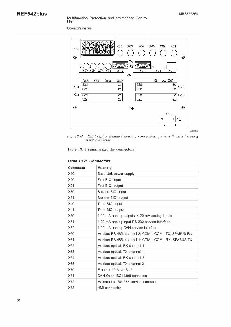
Fig. 18.-2 REF542plus standard housing connections plate with mixed analoginput connector
Table 18.-1 summarizes the connectors.
Table 18.-1 Connectors
Connector Meaning
X10 Base Unit power supply
X20 First BIO, input
X21 First BIO, output
X30 Second BIO, input
X31 Second BIO, output
X40 Third BIO, input
X41 Third BIO, output
X50 4-20 mA analog outputs, 4-20 mA analog inputs
X51 4-20 mA analog input RS 232 service interface
X52 4-20 mA analog CAN service interface
X60 Modbus RS 485, channel 2; COM L-COM I TX; SPABUS RX
X61 Modbus RS 485, channel 1; COM L-COM I RX; SPABUS TX
X62 Modbus optical, RX channel 1
X63 Modbus optical, TX channel 1
X64 Modbus optical, RX channel 2
X65 Modbus optical, TX channel 2
X70 Ethernet 10 Mb/s Rj45
X71 CAN Open ISO11898 connector
X72 Mainmodule RS 232 service interface
X73 HMI connection
68
REF542plusMultifunction Protection and Switchgear ControlUnit
Operator's manual
1MRS755869

69
Table 18.-1 Connectors (Continued)
Connector Meaning
X74 Time synch input
X75 HSTS Input
X76 HSTS Input
X77 HSTS Output
X80 Analog inputs
X81 Sensor 1
X82 Sensor 2
X83 Sensor 3
X84 Sensor 4
X85 Sensor 5
X86 Sensor 6
X87 Sensor 7
X88 Sensor 8
18.1. Analog Inputs
REF542plus can have a maximum of 8 analog input channels. These inputsare divided into three measurement groups:
* Measurement Group 1: channel 1, channel 2, channel 3* Measurement Group 2: channel 4, channel 5, channel 6* Measurement Group 3: channel 7, channel 8
Group 1 and group 2 have to be homogeneous, which means they canmeasure 3 currents or 3 voltages. For example, measurements of 1 currentand 2 voltages are not allowed.
Group 3 can get any type of signals: 2 currents, 2 voltages, 1 current and 1voltage and so on. Group 1 and group 2 can be used for homogeneous currentor voltage measurements both from instrument transformers and non-conventional sensors. Group 3 can be used in a heterogeneous way.
Channel 7 and 8 in group 3 can be used for earth-fault current with CT typeinput; residual voltage, or for the synchrocheck function with VT or sensortype input.
The input CT 0.2A is commonly used with a toroidal transformer forsensitive earth-fault current measurement.
Instrument current transformers can have secondary windings ratio /1 A or /5A. The primary nominal current (for example 400 A) is selected with theOperating Tool. The secondary current (for example /5 A) is automaticallyselected connecting the right wire to the analog input module.
1MRS755869
Multifunction Protection and Switchgear ControlUnit
Operator's manual
REF542plus

The Rogowsky coil can be used for current sensing. The correct ratio of theRogowsky coil is selected with the Operating Tool. The resistive divider canbe used for voltage sensing. The ratio is selected with the Operating Tool. Thephysical input on the unit is the same both for voltage and current sensing, theselection is done via the Operating Tool. Therefore, it is possible for exampleto use 6 Rogowsky coils, 6 voltage dividers, or 3 Rogowsky coils and 3voltage dividers.
To detect which analog input module is present inside the unit, look in theidentification label stick on the unit itself, or on the HMI service page underthe HW identification submenu.
A051450
Fig. 18.1.-1 Connector for sensors analog input module
The analog input for sensor is the same both for voltage and current sensing.To find out whether an input is for current or for voltage, the Operating Toolis needed. X81 corresponds to analog input 1 (sensor 1 in the OperatingTool), X82 to analog input 2 (sensor 2 in the Operating Tool) and so forth.
A051451
Fig. 18.1.-2 Connector for conventional instrument transformers
The connector for conventional instrument transformer has twenty-four pins.The following Table 18.1.-1 defines which input is connected to what:
Table 18.1.-1 Connection table for conventional instrumenttransformers
VT (100-110/) CT (1-5A) CT (0.2A)
1 T5/B T5/2
2 T3/B T3/2
3 T1/B T1/2
4 T8/B T8/2 T8/A
5 T5/R T5/1
6 T3/R T3/3
7 T1/3
8 T8/R T8/3 T8/B
70
REF542plusMultifunction Protection and Switchgear ControlUnit
Operator's manual
1MRS755869

71
Table 18.1.-1 Connection table for conventional instrumenttransformers (Continued)
9 T5/3
10 T3/1
11 T1/R T1/1
12 T8/1
13 T4/3
14 T2/B T2/2
15 T6/3
16 T7/B T7/2 T7/A
17 T4/B T4/2
18 T2/3
19 T6/B T6/2
20 T7/R T7/3 T7/B
21 T4/R T4/1
22 T2/R T2/1
23 T6/R T6/1
24 T7/1
B: Black wire for voltage transformer.
R: Red wire for voltage transformer.
1: 1 A input for current transformer.
2: Common input for current transformer.
3: 5 A input for current transformer.
Example:
To determine the pins for the analog input module 1VCF750170R0817:3CTs, 3VTs, 1CTs; used with transformers with 1 A on the secondarywindings.
The following connection must be done:
Analog input 1; the current transformer for phase 1 must be connected on pins11 and 3 (common).
Analog input 2; the current transformer for phase 2 must be connected on pins22 and 14 (common).
Analog input 3; the current transformer for phase 3 must be connected on pins10 and 2 (common).
Analog input 4; the voltage transformer for phase 1 to earth must beconnected on pins 21 and 17.
1MRS755869
Multifunction Protection and Switchgear ControlUnit
Operator's manual
REF542plus

Analog input 5; the voltage transformer for phase 2 to earth must beconnected on pins 5 and 1.
Analog input 6; the voltage transformer for phase 3 to earth must beconnected on pins 23 and 19.
Analog input 7, for the toroidal transformer for the residual current must beconnected on pins 24 and 16 (common).
A051453
Fig. 18.1.-3 Connector for mixed analog input module
The picture above shows the connector for the mixed analog input modulewhen both sensors and conventional instrument transformers are used. Tofind out which connector is used for what, identify the module code from theidentification label stick on the unit and see Table 18.1.-1.
18.2. Binary inputs and outputs
Binary input and output modules use the following connectors:
X20 (inputs), X21 (outputs) for the first module.
X30 (inputs), X31 (outputs) for the second module.
X40 (inputs), X41 (outputs) for the third module, available with the widehousing only.
REF542plus can be equipped with two different types of binary inputs andoutputs modules: static or with electromechanical relays.
18.2.1. Static
In the static module, digital inputs are implemented with optocouplers anddigital outputs are implemented with power transistors. Two different moduletypes are available, with control coil continuity and without.
Each module features: 14 digital inputs, 3 power outputs, 4 normal outputs, 2signal outputs, 1 watchdog output and optionally 2 coil supervision circuits.For more information, refer to the REF542plus Technical Catalogue.
72
REF542plusMultifunction Protection and Switchgear ControlUnit
Operator's manual
1MRS755869

73
A051454
Fig. 18.2.1.-1 Two static binary inputs and output modules
18.2.2. Electromechanical
In the electromechanical module, digital inputs are implemented withoptocouplers and digital outputs are implemented with electromechanicalrelays.
REF542plus can be equipped with 2 different electromechanical moduletypes, BIO2 and BIO3. The modules are functionally equivalent, with slightvariations. These modules are available in different versions. For moreinformation, refer to the REF542plus Technical Catalogue.
18.2.2.1. BIO3
Twelve different types of BIO3 are available depending upon the supplyvoltage and other features.
Table 18.2.2.1.-1 BIO3 types and codes
BIO3 Code Description
1VCF750132R0801 Binary I/O3 - 20..90 VDC/14VDC Standard
1VCF750132R0803 Binary I/O3 - 20..90 VDC/14VDC Standard withStatic Channel
1MRS755869
Multifunction Protection and Switchgear ControlUnit
Operator's manual
REF542plus
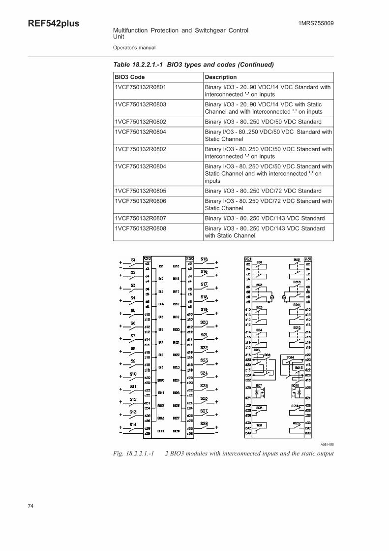
Table 18.2.2.1.-1 BIO3 types and codes (Continued)
BIO3 Code Description
1VCF750132R0801 Binary I/O3 - 20..90 VDC/14 VDC Standard withinterconnected '-' on inputs
1VCF750132R0803 Binary I/O3 - 20..90 VDC/14 VDC with StaticChannel and with interconnected '-' on inputs
1VCF750132R0802 Binary I/O3 - 80..250 VDC/50 VDC Standard
1VCF750132R0804 Binary I/O3 - 80..250 VDC/50 VDC Standard withStatic Channel
1VCF750132R0802 Binary I/O3 - 80..250 VDC/50 VDC Standard withinterconnected '-' on inputs
1VCF750132R0804 Binary I/O3 - 80..250 VDC/50 VDC Standard withStatic Channel and with interconnected '-' oninputs
1VCF750132R0805 Binary I/O3 - 80..250 VDC/72 VDC Standard
1VCF750132R0806 Binary I/O3 - 80..250 VDC/72 VDC Standard withStatic Channel
1VCF750132R0807 Binary I/O3 - 80..250 VDC/143 VDC Standard
1VCF750132R0808 Binary I/O3 - 80..250 VDC/143 VDC Standardwith Static Channel
A051455
Fig. 18.2.2.1.-1 2 BIO3 modules with interconnected inputs and the static output
74
REF542plusMultifunction Protection and Switchgear ControlUnit
Operator's manual
1MRS755869

75
18.3. Other connections
18.3.1. Analog outputs 0/4-20 mA
The 4 analog outputs, when present, are available at connector X50accordingly to the following …x-ref…diagram. The not used pins, includingthe shielding of the cable are connected to ground.
A051457
Fig. 18.3.1.-1 0/4-20 mA analog outputs
18.3.2. Analog inputs 4-20 mA
When present, the 4-20 mA analog input module uses connector X50.Sensor’s connections are shown in the picture below…x-ref… X51 and X52are service interfaces of no use for the user. The output contact BO1 is for thefuture use.
1MRS755869
Multifunction Protection and Switchgear ControlUnit
Operator's manual
REF542plus

A051458
Fig. 18.3.2.-1 4-20 mA analog inputs
Only passive sensors, for example those that are powered fromthe loop can be connected to the 4…20 mA analog inputmodule.
18.3.3. Communication module
The communication module uses connectors from X60, X61, X62, X63, X64and X65 depending on the physical media type (RS 845, glass or plasticfiber).
18.3.4. Power supply
Power supply for the Base Unit is X10.
76
REF542plusMultifunction Protection and Switchgear ControlUnit
Operator's manual
1MRS755869

77
18.3.5. Time synchronization
The optical input for time synchronization is X74.
18.3.6. HMI
A051459
Fig. 18.3.6.-1 HMI connectors
The HMI power supply is X10 (1 is +, 2 is -), while the serial cable to connectthe Base Unit must be connected to X20.
Respect the right polarity on the HMI power supply to avoiddamages to the unit.
1MRS755869
Multifunction Protection and Switchgear ControlUnit
Operator's manual
REF542plus

78

79
19. Appendix B: Menu structureThis chapter illustrates the HMI menu structure with the submenus notdescribed in the document.
To access the menu structure, press .
A051460
Fig. 19.-1 REF542plus menu
The accessing in some submenus is restricted to a few operating modes asdescribed in the Table 19.-1 below.
Table 19.-1 Menu access table
Menu / Submenu page NoControl
LocalControl
RemoteControl
L & RControl
Prot.Set
Prot.Oper.
E-Key status Yes Yes Yes Yes Yes Yes
Measurements Yes Yes Yes Yes Yes Yes
Alarms Yes Yes Yes Yes Yes Yes
Reset page
- Alarm - - - - Yes Yes
- Max. values - - - - No No
- Energy values - - - - No No
- CB cycles - - - - No No
- Fault recorder - - - - Yes No
- Start/Trip - - - - Yes No
- Counters - - - No No
Start/Trip page Yes Yes Yes Yes Yes Yes
Active set page
- View parameter Yes Yes Yes Yes Yes Yes
- Change set No No No No Yes No
Protection functions
1MRS755869
Multifunction Protection and Switchgear ControlUnit
Operator's manual
REF542plus

Table 19.-1 Menu access table (Continued)
Menu / Submenu page NoControl
LocalControl
RemoteControl
L & RControl
Prot.Set
Prot.Oper.
- View Parameter Yes Yes Yes Yes Yes Yes
- Change Parameter - - - - Yes No
Control parameters
- View parameter - - - - Yes Yes
- Change parameter - - - - Yes No
Service page
- Statistics Yes Yes Yes Yes Yes Yes
- Versions Yes Yes Yes Yes Yes Yes
- Communicationaddress
Yes Yes Yes Yes Yes Yes
- LCD contrast Yes Yes Yes Yes Yes Yes
- MC time Yes Yes Yes Yes Yes Yes
- Load flow direction Yes Yes Yes Yes Yes Yes
- Autoreclosure mode No No No No Yes No
- IEC 60870-5-103module
Yes Yes Yes Yes No No
Test page
- HMI Control Unit Yes Yes Yes Yes Yes Yes
- Primary No Yes No No No No
19.1. Reset page
From this page, it is possible to reset alarms and other quantities. Some resetactions are possible only if REF542plus is in the proper mode. For example,the fault recorder can be reset only in the set protection mode. An attempt toreset it in the operational mode will be denied.
80
REF542plusMultifunction Protection and Switchgear ControlUnit
Operator's manual
1MRS755869

81
A051461
Fig. 19.1.-1 Attempt to resetting the fault recorder in the wrong mode
Select the quantity to reset with UP and DOWN and press ENTERto execute.
A051462
Fig. 19.1.-2 Resetting a quantity in the proper mode
The quantities that can be reset are:
Reset alarm: can only be reset, if there is no active alarm present anymore. Anattempt to reset an alarm caused for example by an interrupted open coil isimpossible as long as the coil is not replaced.
1MRS755869
Multifunction Protection and Switchgear ControlUnit
Operator's manual
REF542plus

Reset max. values: this sub menu resets the maximum and mean currentvalues in the observation period. Also the sum of switched off current is resetfrom here.
Reset energy values: all the energy values (active, reactive, apparent) are resetfrom here.
Reset CB cycles: a circuit breaker cycle is a close operation and thesubsequent open operation. The unit sums the cycles. This cycle number isreset from here.
Reset fault recorder: the fault recorder data is cleared from here.
Reset Start/Trip: the start and trip protection events are cleared from here.
Reset counters: the unit working hours are reset from here.
19.2. Service page
The service page menu is composed of several submenus. Browse throughthe submenus with UP and DOWN buttons. Press ENTER toenter the selected submenu.
A051463
Fig. 19.2.-1 Service page menu
The service page contains the following submenus.
Statistics
This submenu shows the FUPLA cycle time and other information related tothe current configuration in the unit.
82
REF542plusMultifunction Protection and Switchgear ControlUnit
Operator's manual
1MRS755869

83
A051464
Fig. 19.2.-2 Statistics submenu
Versions
This submenu displays information on the firmware versions loaded insidethe unit.
A051465
Fig. 19.2.-3 Versions submenu
Hardware identification
This submenu shows the reference information of the hardware modulesinstalled into REF542plus.
1MRS755869
Multifunction Protection and Switchgear ControlUnit
Operator's manual
REF542plus
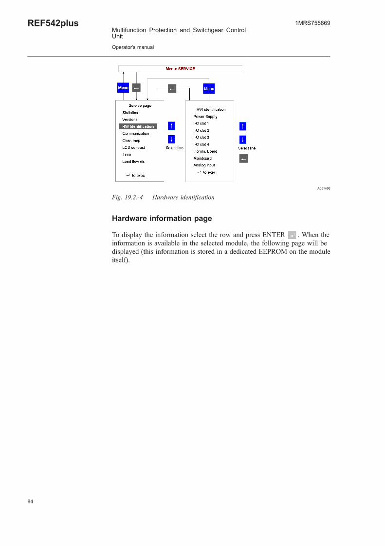
A051466
Fig. 19.2.-4 Hardware identification
Hardware information page
To display the information select the row and press ENTER . When theinformation is available in the selected module, the following page will bedisplayed (this information is stored in a dedicated EEPROM on the moduleitself).
84
REF542plusMultifunction Protection and Switchgear ControlUnit
Operator's manual
1MRS755869

85
A051467
Fig. 19.2.-5 Hardware information page
When the information from the module is not available the following page isdisplayed.
A051468
Fig. 19.2.-6 Hardware information is not available
1MRS755869
Multifunction Protection and Switchgear ControlUnit
Operator's manual
REF542plus
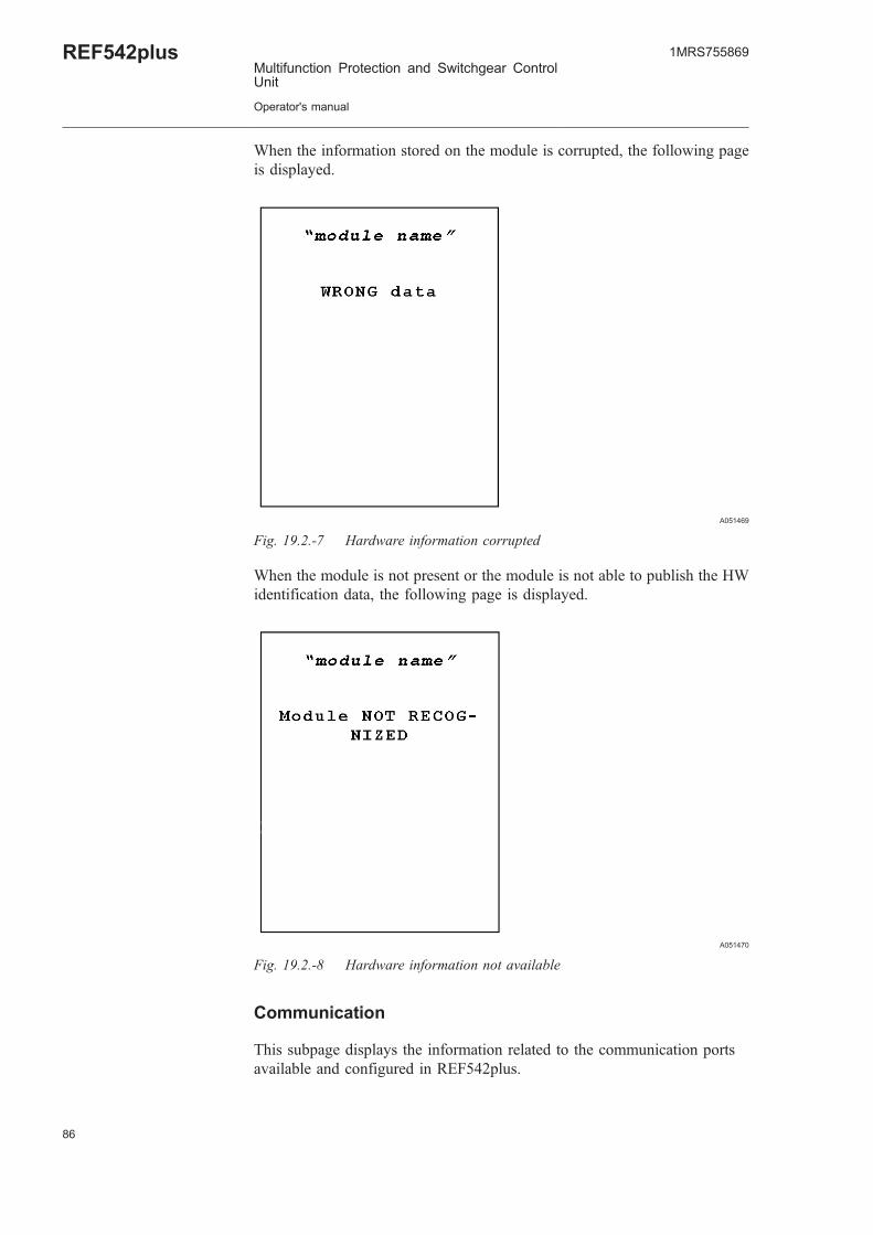
When the information stored on the module is corrupted, the following pageis displayed.
A051469
Fig. 19.2.-7 Hardware information corrupted
When the module is not present or the module is not able to publish the HWidentification data, the following page is displayed.
A051470
Fig. 19.2.-8 Hardware information not available
Communication
This subpage displays the information related to the communication portsavailable and configured in REF542plus.
86
REF542plusMultifunction Protection and Switchgear ControlUnit
Operator's manual
1MRS755869

87
A051641
Fig. 19.2.-9 Communication subpage visualization
When the port is not installed or configured, the following page will bedisplayed.
A051642
Fig. 19.2.-10 Communication module is not installed
When the COM-L module for LON communication is installed and active,the following page displays the configured Node ID.
1MRS755869
Multifunction Protection and Switchgear ControlUnit
Operator's manual
REF542plus

A051643
Fig. 19.2.-11 LON communication module Node Id
When the Modbus module is installed and properly working, the followingpage is displayed.
A051644
Fig. 19.2.-12 Modbus communication module page
By selecting the row related to port A or B and pressing , it is possible tochange the port communication address.
88
REF542plusMultifunction Protection and Switchgear ControlUnit
Operator's manual
1MRS755869

89
IEC Communication page
When the IEC 60870-5-103 communication module is installed the followingpage is displayed.
A051645
Fig. 19.2.-13 IEC 103 communication module page
In this subpage, it is possible to block the monitoring direction of the module.For more information, refer to the Communication Module User Manual.
A051646
Fig. 19.2.-14 IEC 103 communication, blocking the monitoring direction
1MRS755869
Multifunction Protection and Switchgear ControlUnit
Operator's manual
REF542plus

The IEC Test mode menu allows setting and resetting the test mode of theIEC module. For more information, refer to the Communication Module UserManual.
A051647
Fig. 19.2.-15 IEC 103 communication module test mode subpage
SPA bus communication subpage
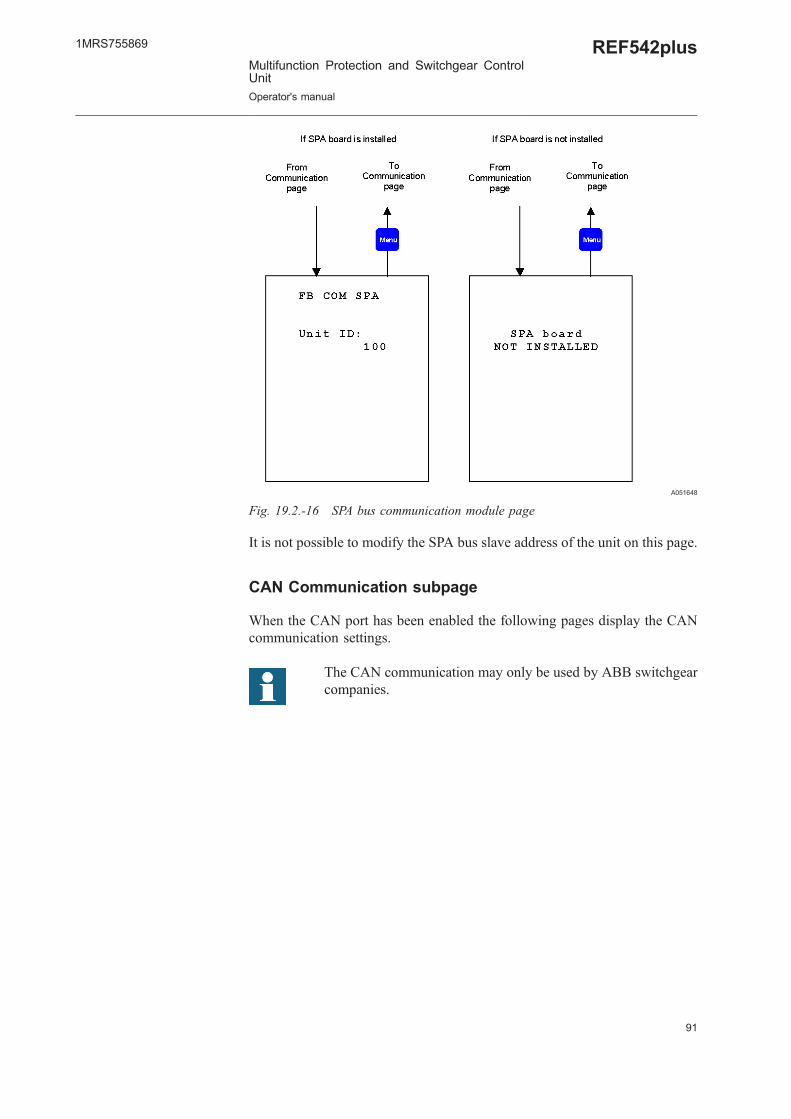
When the SPA bus communication module is installed, the following page isdisplayed.
90
REF542plusMultifunction Protection and Switchgear ControlUnit
Operator's manual
1MRS755869
91
A051648
Fig. 19.2.-16 SPA bus communication module page
It is not possible to modify the SPA bus slave address of the unit on this page.
CAN Communication subpage
When the CAN port has been enabled the following pages display the CANcommunication settings.
The CAN communication may only be used by ABB switchgearcompanies.
1MRS755869
Multifunction Protection and Switchgear ControlUnit
Operator's manual
REF542plus

A051649
Fig. 19.2.-17 CAN communication port page
Only channel 1 is currently available. To enter the next subpage, selectChannel 1 and press ENTER . The following page is displayed.
A051650
Fig. 19.2.-18 CAN communication port subpage
92
REF542plusMultifunction Protection and Switchgear ControlUnit
Operator's manual
1MRS755869
93
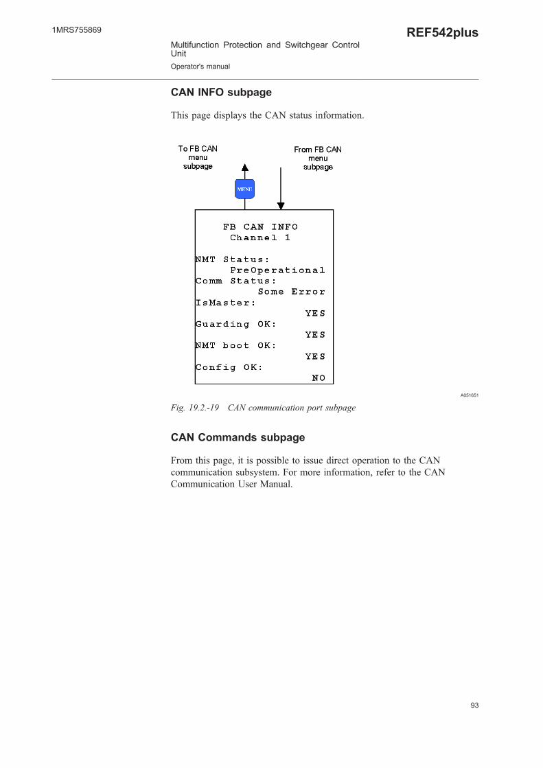
CAN INFO subpage
This page displays the CAN status information.
A051651
Fig. 19.2.-19 CAN communication port subpage
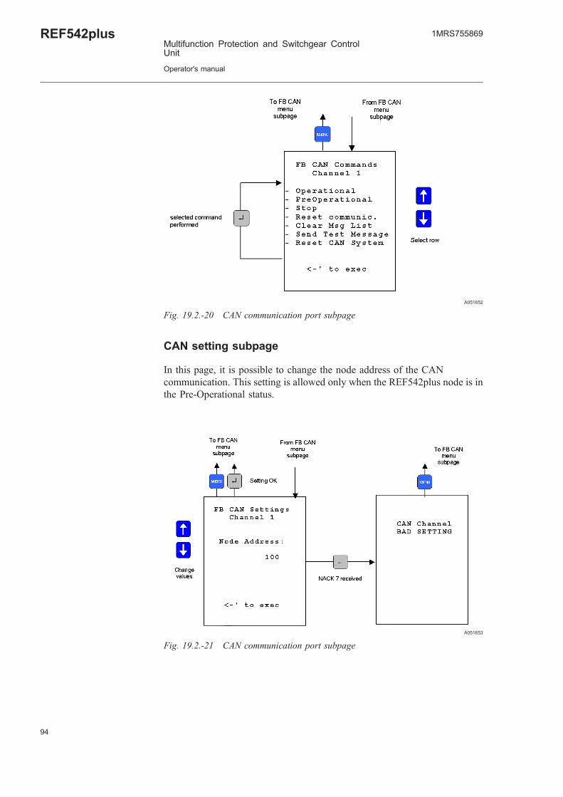
CAN Commands subpage
From this page, it is possible to issue direct operation to the CANcommunication subsystem. For more information, refer to the CANCommunication User Manual.
1MRS755869
Multifunction Protection and Switchgear ControlUnit
Operator's manual
REF542plus
A051652
Fig. 19.2.-20 CAN communication port subpage
CAN setting subpage
In this page, it is possible to change the node address of the CANcommunication. This setting is allowed only when the REF542plus node is inthe Pre-Operational status.
A051653
Fig. 19.2.-21 CAN communication port subpage
94
REF542plusMultifunction Protection and Switchgear ControlUnit
Operator's manual
1MRS755869

95
HMI Communication subpage
In this page, it is possible to change the Base Unit slave address used tocommunicate with the HMI.
When the Base Unit address is changed, the communicationwith the HMI is lost. To restore it, the Base Unit address must beinserted in the HMI as well. Select the menu item Base UnitSlave Address and insert the same address of the Base Unit.
A051654
Fig. 19.2.-22 HMI, changing Base Unit address to be polled
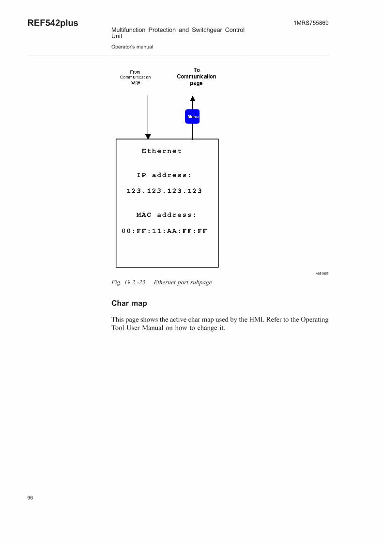
Ethernet communication subpage
This page shows the current settings of the Ethernet communicationsubsystem. Here, it is possible to visualize the IP and MAC address. The IPand MAC addresses cannot be changed from this page.
1MRS755869
Multifunction Protection and Switchgear ControlUnit
Operator's manual
REF542plus
A051655
Fig. 19.2.-23 Ethernet port subpage
Char map
This page shows the active char map used by the HMI. Refer to the OperatingTool User Manual on how to change it.
96
REF542plusMultifunction Protection and Switchgear ControlUnit
Operator's manual
1MRS755869

97
A051656
Fig. 19.2.-24 Char map page
LCD contrast
The LCD screen contrast can be adapted to different light condition from thissubmenu.
A051657
Fig. 19.2.-25 Adjusting the LCD contrast
1MRS755869
Multifunction Protection and Switchgear ControlUnit
Operator's manual
REF542plus

Load flow direction
The load flow direction determines how REF542plus computes energy andpower. It is set with the Operating Tool and it is also dependent upon thecurrent and voltage transformers (or sensors) connections in the primaryparts.
* FORWARD: the power is flowing from the switchgear to the load(outgoing feeder).
* BACKWARD: the power is flowing into the switchgear (incomingfeeder).
A051658
Fig. 19.2.-26 Load flow direction visualization
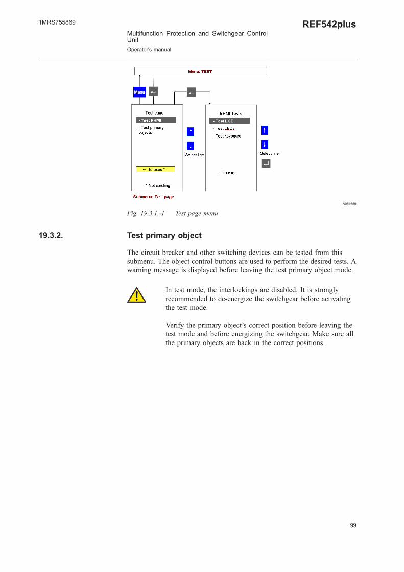
19.3. Test page
This submenu allows testing the HMI and the primary part of the switchgear.
19.3.1. Test HMI
When the test HMI is selected, all its features will be tested by switchingthem on and off.
HMI buttons are not available during the test. The displayedinformation on the HMI does not reflect the switchgear’s actualstatus. REF542plus is protecting the switchgear during the HMItest. The HMI test takes a few seconds.
98
REF542plusMultifunction Protection and Switchgear ControlUnit
Operator's manual
1MRS755869
99
A051659
Fig. 19.3.1.-1 Test page menu
19.3.2. Test primary object
The circuit breaker and other switching devices can be tested from thissubmenu. The object control buttons are used to perform the desired tests. Awarning message is displayed before leaving the test primary object mode.
In test mode, the interlockings are disabled. It is stronglyrecommended to de-energize the switchgear before activatingthe test mode.
Verify the primary object’s correct position before leaving thetest mode and before energizing the switchgear. Make sure allthe primary objects are back in the correct positions.
1MRS755869
Multifunction Protection and Switchgear ControlUnit
Operator's manual
REF542plus

100

101
20. Appendix C: Tripping time indicationThe example below indicates explain tripping time indication on REF542plusHMI. The example refers to the overcurrent instantaneous protectionfunction.
Setting values in REF542plus are:
Set time = 80 ms
Set threshold = 0,1 In
A051660
Fig. 20.-1 Start/Trip events
Event nr.1
The protection function enters the start condition, for example the current isabove the set threshold, at 01/01/2004, 16:02:22.138, absolute time. Thearrow 1 indicates the time, see Fig. 20.-1.
Event nr. 3
The set time has elapsed with the current above the set threshold. Therefore,the trip signal is generated at 01/01/2004, 16:02:22.203, absolute time. Thearrow 3 indicates the time, see Fig. 20.-1.
The set time in REF542plus, 80 ms in this case, must be compared to the timeobtained by the following computation:
(Trip signal time: event nr. 3 time)-(start time: event nr.1 time)+compensationtime(*)
In this specific case assuming a BIO3 module inside the REF542plus:
1MRS755869
Multifunction Protection and Switchgear ControlUnit
Operator's manual
REF542plus

203 ms-138 ms+15 ms=80 ms.
The time “Start L1”, 5’028 ms long, indicated by the arrow 2 (see Fig. 20.-1),is the time interval during which the protection remains in the start state (forexample active) inside REF542plus.
(*)The compensation time takes into account the signal processing inside theunit and switching time of the contact. The values for the different modulesare:
Static IO module 10 ms
BIO3 module 15 ms
BIO2 module 20 ms.
102
REF542plusMultifunction Protection and Switchgear ControlUnit
Operator's manual
1MRS755869


ABB OyDistribution AutomationP.O. Box 699FI-65101 VaasaFINLAND+358 10 22 11+358 10 22 224 1094http://www.abb.com/substationautomation
1MRS755869
EN
2/2006