
REEDJET AUS 100cc TaG - KartSportNews – karting … motor is a single cylinder using the two...
33
MAN-033 REEDJET AUS 100cc – TaG 01/11/04 INSTALLATION MANUAL
Transcript of REEDJET AUS 100cc TaG - KartSportNews – karting … motor is a single cylinder using the two...

MAN-033
REEDJET AUS 100cc – TaG
01/11/04
INSTALLATION MANUAL

MAN-072 1
GENERAL DESCRIPTION OF ENGINE
This engine of the "TaG" series (Touch and Go) has been expressly designed and developed to power Karts for hobby racing on closed tracks, destined for this specific purpose. When designing this new line of engines, the technical solutions already adopted for the high performance engines were applied, in order to guarantee the highest reliability of components, when the operating limits are respected. The motor is a single cylinder using the two stroke principle. The cylinder and the crankcase are in aluminium alloy. The pressed in liner is made of centrifugated cast iron, fully machined to guarantee the best possible stability and sliding homogeneity. The head is separated from the cylinder and secured by studs. The crankshaft is built and supported by ball-bearings. The crankshaft is of steel alloy, hardened and tempered, as is the connecting rod which runs on roller bearings. The ignition includes a 2 pole stator/rotor, an H.T. coil, a starter relay and complete wiring harness. The spark is generated also without a battery: therefore, in case of emergency, the engine can be started with an external starter unit. The engine has an integrated electric starter. By pushing the start button, the starter activates a Bendix type gear that engages the starter ring assembled on the clutch. The engine is provided with a dry centrifugal clutch with low maintenance and with interchangeable sprocket. The carburettor is a diaphragm type (series Tillotson HL), it includes an integrated fuel pump and filter, and it is able to operate in any position. The battery (12 V - 9Ah) is a sealed, no maintenance battery and is supplied together with a support box, which can be easily adapted to all existing chassis. The exhaust system, included in the engine package, is already tuned and optimized to ensure the best possible performance.

MAN-072 2
ENGINE FEATURES – OPERATIONAL LIMITS
Engine features:
x Cycle: x Original cubic capacity: x Original bore: x Max. theoretical bore: x Stroke: x Lubrification : x Induction: x Carburettor: x Cooling: x Ignition: x Electric Starter: x Clutch:
OTTO / 2 stroke 100 cm³ 48.20 mm 48.53 mm 54.05 mm max Mixture 5% Reed Valve in crankcase Diaphragm type , Tillotson HL 398A - Ø23mm Free Air Analogical / 2 poles, slotted with internal rotor 12V/0.30 kW Automatic, dry centrifugal
ATTENTION:
Never exceed the above limits, no obligation of IAME S.p.A. exists in case the above limits are exceeded.
Operational RPM limits (the motor not included RPM Limiter):
Max.RPM / 1’ : 15.000 RPM
CONTENT OF THE ENGINE PACKAGE
EXHAUST GRUOP Quantity x Exhaust muffler spring 2 x Exhaust manifold (no restricted / restricted Ø19mm) 1 x Exhaust muffler 1
INDUCTION GROUP x Tillotson Carburettor HL 398A (Venturi Ø23mm) 1 x Inlet Silencer 1 x Inlet Silencer Rubber Manifold 1 x Inlet Silencer Support + Clamps 1 x Carburettor throttle lever cable 1 x Inlet manifold carburettor pipe 1
ELECTRICAL GROUP x Battery 12 V – 9 Ah 1 x Wiring Harness (with push buttons) 1 x Push Buttons Support Bracket 1 x Battery Support 1 x Battery fix straps 1 x Battery Fixing Clamps 2 x H.T. Coil 1 x Fixing Clamps 8 x Sparkplug NGK BR 10 EG 1 x Sparkplug Cap 1
MISCELLANEUOS x Clutch Cover + Accessories 1 x Dual-Lock fixing tape 1

MAN-072 3
ACCESSORIES
EXHAUST GROUP
COPERCHIO FRIZIONE
INLET SILENCER + FILTER TILLOTSON CARBURETTOR SPARKPLUG KIT
CLUTCH COVER + H.T. COIL
PUSH BUTTONS BRACKET
WIRING HARNESS
BATTERY SUPPORT KIT
MAN-072 4
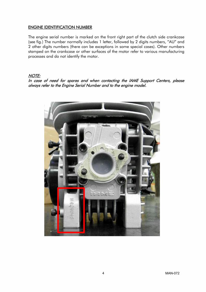
ENGINE IDENTIFICATION NUMBER
The engine serial number is marked on the front right part of the clutch side crankcase
(see fig.) The number normally includes 1 letter, followed by 2 digits numbers, “AU” and 2 other digits numbers (there can be exceptions in some special cases). Other numbers
stamped on the crankcase or other surfaces of the motor refer to various manufacturing
processes and do not identify the motor.
NOTE:
In case of need for spares and when contacting the IAME Support Centers, please
always refer to the Engine Serial Number and to the engine model.
MAN-072 5
2- PREPARATION AND INSTALLATION OF THE ENGINE ON THE CHASSIS
NOTE: In case the engine is supplied already assembled on the chassis, it is at care of the assembler to follow these instructions. The final customer, in this case, can skip this section and can start reading from section 4. Whenever the engine or a component is disassembled, it is necessary to always follow the under shown instructions for proper reassembly.
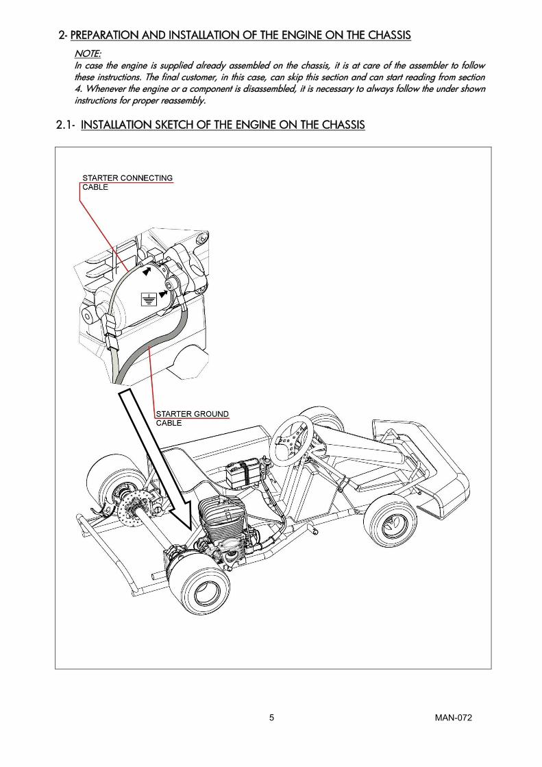
2.1- INSTALLATION SKETCH OF THE ENGINE ON THE CHASSIS
MAN-072 6
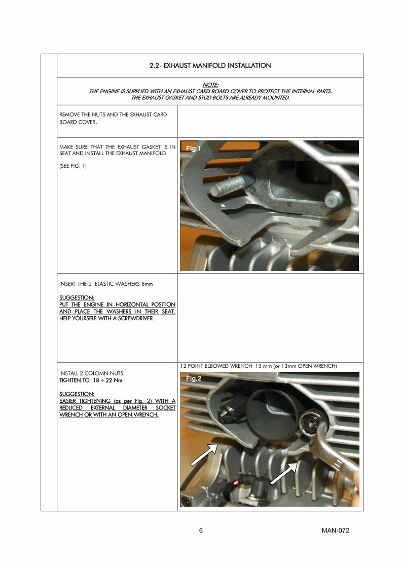
2.2- EXHAUST MANIFOLD INSTALLATION
NOTE: THE ENGINE IS SUPPLIED WITH AN EXHAUST CARD BOARD COVER TO PROTECT THE INTERNAL PARTS.
THE EXHAUST GASKET AND STUD BOLTS ARE ALREADY MOUNTED.
REMOVE THE NUTS AND THE EXHAUST CARD
BOARD COVER.
MAKE SURE THAT THE EXHAUST GASKET IS IN
SEAT AND INSTALL THE EXHAUST MANIFOLD.
(SEE FIG. 1)
INSERT THE 2 ELASTIC WASHERS 8mm SUGGESTION: PUT THE ENGINE IN HORIZONTAL POSITION AND PLACE THE WASHERS IN THEIR SEAT. HELP YOURSELF WITH A SCREWDRIVER.
INSTALL 2 COLOMN NUTS. TIGHTEN TO 18 ÷ 22 Nm. SUGGESTION: EASIER TIGHTENING (as per Fig. 2) WITH A REDUCED EXTERNAL DIAMETER SOCKET WRENCH OR WITH AN OPEN WRENCH.
12 POINT ELBOWED WRENCH 13 mm (or 13mm OPEN WRENCH)
Fig.1
Fig.2
MAN-072 7
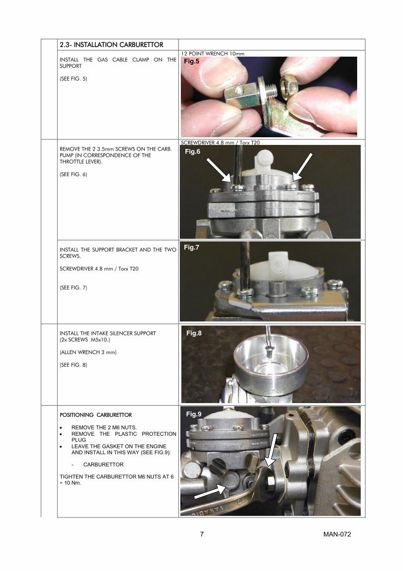
2.3- INSTALLATION CARBURETTOR INSTALL THE GAS CABLE CLAMP ON THE
SUPPORT
(SEE FIG. 5)
12 POINT WRENCH 10mm
REMOVE THE 2 3.5mm SCREWS ON THE CARB.
PUMP (IN CORRESPONDENCE OF THE
THROTTLE LEVER).
(SEE FIG. 6)
SCREWDRIVER 4.8 mm / Torx T20
INSTALL THE SUPPORT BRACKET AND THE TWO
SCREWS.
SCREWDRIVER 4.8 mm / Torx T20
(SEE FIG. 7)
INSTALL THE INTAKE SILENCER SUPPORT
(2x SCREWS M5x10.)
(ALLEN WRENCH 3 mm)
(SEE FIG. 8)
POSITIONING CARBURETTOR
x REMOVE THE 2 M6 NUTS. x REMOVE THE PLASTIC PROTECTION
PLUG x LEAVE THE GASKET ON THE ENGINE
AND INSTALL IN THIS WAY (SEE FIG.9):
- CARBURETTOR TIGHTEN THE CARBURETTOR M6 NUTS AT 6 ÷ 10 Nm.
Fig.5
Fig.9
Fig.6
Fig.7
Fig.8
MAN-072 8
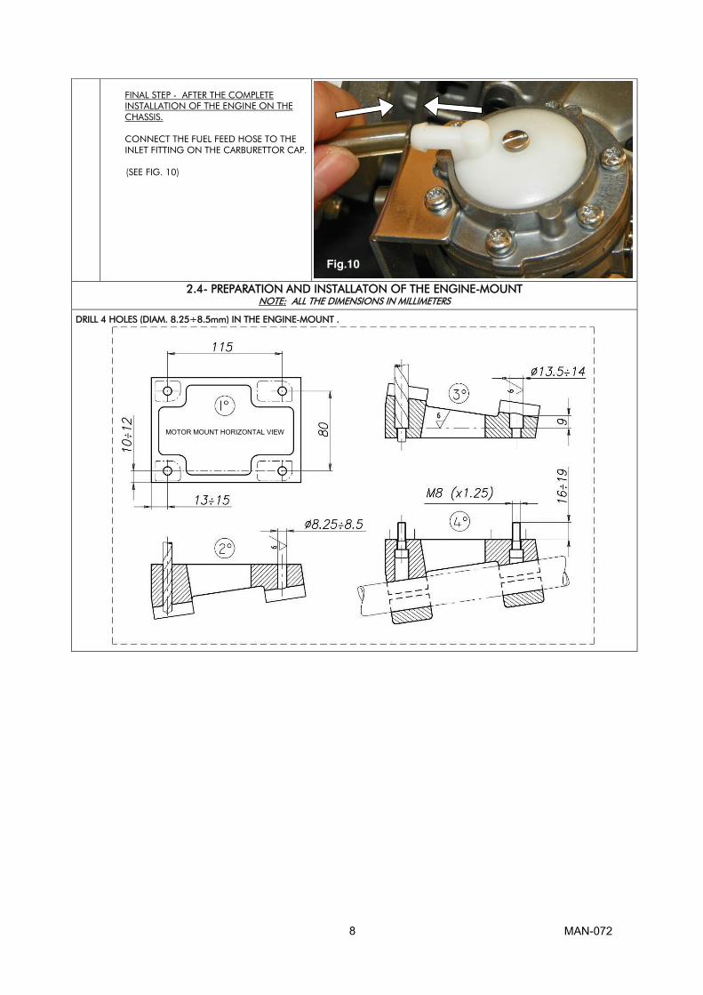
FINAL STEP - AFTER THE COMPLETE
INSTALLATION OF THE ENGINE ON THE
CHASSIS.
CONNECT THE FUEL FEED HOSE TO THE
INLET FITTING ON THE CARBURETTOR CAP.
(SEE FIG. 10)
2.4- PREPARATION AND INSTALLATON OF THE ENGINE-MOUNT
NOTE: ALL THE DIMENSIONS IN MILLIMETERS
DRILL 4 HOLES (DIAM. 8.25÷8.5mm) IN THE ENGINE-MOUNT .
Fig.10
MOTOR MOUNT HORIZONTAL VIEW
MAN-072 9
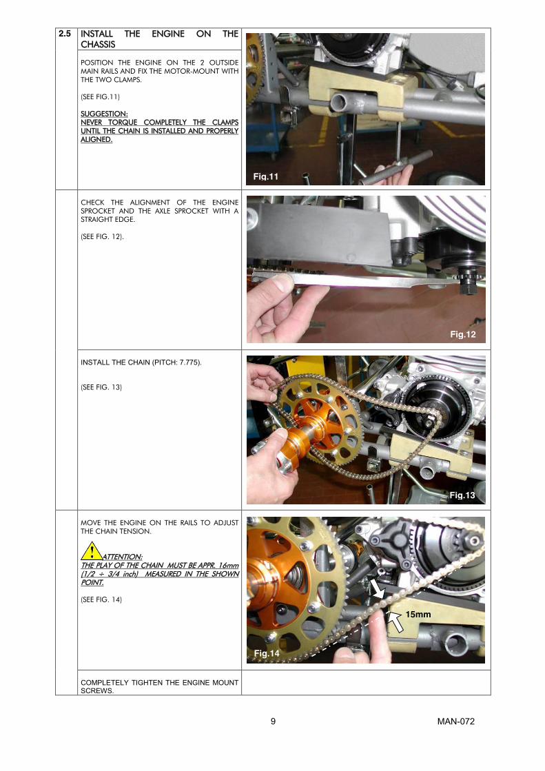
2.5 INSTALL THE ENGINE ON THE
CHASSIS
POSITION THE ENGINE ON THE 2 OUTSIDE
MAIN RAILS AND FIX THE MOTOR-MOUNT WITH
THE TWO CLAMPS.
(SEE FIG.11)
SUGGESTION:
NEVER TORQUE COMPLETELY THE CLAMPS
UNTIL THE CHAIN IS INSTALLED AND PROPERLY
ALIGNED.
CHECK THE ALIGNMENT OF THE ENGINE
SPROCKET AND THE AXLE SPROCKET WITH A
STRAIGHT EDGE.
(SEE FIG. 12).
INSTALL THE CHAIN (PITCH: 7.775). (SEE FIG. 13)
MOVE THE ENGINE ON THE RAILS TO ADJUST
THE CHAIN TENSION.
ATTENTION:
THE PLAY OF THE CHAIN MUST BE APPR. 16mm
(1/2 ÷ 3/4 inch) MEASURED IN THE SHOWN
POINT.
(SEE FIG. 14)
COMPLETELY TIGHTEN THE ENGINE MOUNT SCREWS.
Fig.11
Fig.12
Fig.13
Fig.14
15mm

MAN-072 10
2.6 INSTALL THE CLUTCH COVER WITH
H.T. COIL
ALLEN WRENCH 5 mm
REMOVED THE 3 SCREWS TCEI M6x30 FROM
THE CRANKCASE (SEE FIG. 15) AND INSTALL THE
CLUTCH COVER WITH THE H.T. COIL.
(SEE FIG.16)
TIGHTEN THE 3 SCREW AT 8÷10 Nm
ATTENTION: ALWAYS MAKE SURE THAT THE GROUND CABLE
ALWAYS CONNECTS THE COIL WITH THE
ENGINE. AN INADEQUATE GROUNDING
COULD DAMAGE THE IGNITION BEYOND
REPAIR.
THE POSITION OF THE H.T. COIL HAS BEEN
CHOSEN TO BE AS FAR AS POSSIBLE FROM THE
EXHAUST AS THE EXCESSIVE HEAT COULD
DAMAGE THE COIL BEYOND REPAIR.
Fig.15
Fig.16
MAN-072 11
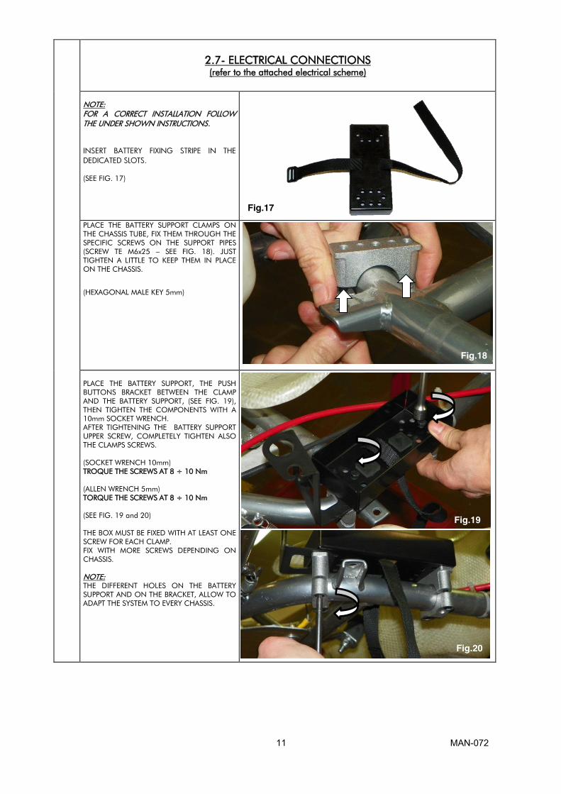
2.7- ELECTRICAL CONNECTIONS
(refer to the attached electrical scheme)
NOTE:
FOR A CORRECT INSTALLATION FOLLOW THE UNDER SHOWN INSTRUCTIONS.
INSERT BATTERY FIXING STRIPE IN THE DEDICATED SLOTS.
(SEE FIG. 17)
PLACE THE BATTERY SUPPORT CLAMPS ON
THE CHASSIS TUBE, FIX THEM THROUGH THE
SPECIFIC SCREWS ON THE SUPPORT PIPES
(SCREW TE M6x25 – SEE FIG. 18). JUST
TIGHTEN A LITTLE TO KEEP THEM IN PLACE
ON THE CHASSIS.
(HEXAGONAL MALE KEY 5mm)
PLACE THE BATTERY SUPPORT, THE PUSH
BUTTONS BRACKET BETWEEN THE CLAMP
AND THE BATTERY SUPPORT, (SEE FIG. 19),
THEN TIGHTEN THE COMPONENTS WITH A
10mm SOCKET WRENCH.
AFTER TIGHTENING THE BATTERY SUPPORT
UPPER SCREW, COMPLETELY TIGHTEN ALSO
THE CLAMPS SCREWS.
(SOCKET WRENCH 10mm)
TROQUE THE SCREWS AT 8 ÷ 10 Nm
(ALLEN WRENCH 5mm)
TORQUE THE SCREWS AT 8 ÷ 10 Nm
(SEE FIG. 19 and 20)
THE BOX MUST BE FIXED WITH AT LEAST ONE
SCREW FOR EACH CLAMP.
FIX WITH MORE SCREWS DEPENDING ON
CHASSIS.
NOTE:
THE DIFFERENT HOLES ON THE BATTERY
SUPPORT AND ON THE BRACKET, ALLOW TO
ADAPT THE SYSTEM TO EVERY CHASSIS.
Fig.17
Fig.18
Fig.19
Fig.20
MAN-072 12
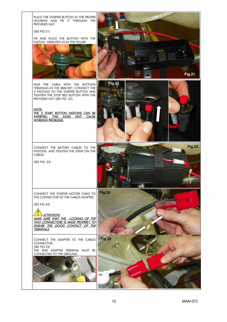
PLACE THE STARTER BUTTON IN THE PROPER
HOUSING AND FIX IT THROUGH THE
PROVIDED NUT.
(SEE FIG.21)
FIX AND PLACE THE BUTTON WITH THE
FASTON ORIENTED AS IN THE FIGURE:
PASS THE CABLE WITH THE BUTTONS
TERMINALS IN THE BRACKET, CONNECT THE
2 FASTONS TO THE STARTER BUTTON AND
TIGHTEN THE STOP RED BUTTON WITH THE
PROVIDED NUT (SEE FIG. 22).
NOTE:
THE 2 START BUTTON FASTONS CAN BE
INVERTED, THIS DOES NOT CAUSE
WORKING PROBLEMS.
CONNECT THE BATTERY CABLES TO THE
FASTONS AND TIGHTEN THE STRAP ON THE
CABLES.
(SEE FIG. 23)
CONNECT THE STARTER MOTOR CABLE TO
THE CONNECTOR OF THE CABLES ADAPTER.
(SEE FIG.24)
ATTENTION:
MAKE SURE THAT THE LOCKING OF THE
TWO CONNECTORS IS MADE PROPERLY TO
ENSURE THE GOOD CONTACT OF THE
TERMINALS.
CONNECT THE ADAPTER TO THE CABLES
CONNECTOR.
(SEE FIG.25)
THE 2ND ADAPTER TERMINAL MUST BE
CONNECTED TO THE GROUND.
Fig.21
Fig.22
Fig.23
Fig.24
Fig.25

MAN-072 13
FIX THE KIT CABLES THROUGH A STRAP
ACCORDING TO THE CHASSIS AND THE
NEED.
(SEE FIG.26)
CONNECT THE SUPERSEAL 4 WAYS MALE
FASTON CONNECTOR TO THE FEMALE
CONNECTOR OF THE STOP CABLE.
(SEE FIG.27)
CONNECT THE MALE FASTON OF THE STOP
CABLE TO THE FEMALE FASTON
CONNECTOR OF THE INGNITION.
(SEE FIG. 28)
CONNECT THE FEMALE FASTON OF THE
INGNITION CABLE ON THE H.T. MALE
FASTON.
(SEE FIG.29)
SCREW THE SPARK PLUG CAP ON THE COIL
HIGH VOLTAGE CABLE.
(SEE FIG. 30)
FIX THE CUP ON THE A.T. CABLE THROUGH A PLASTIC STRAP (SEE FIG. 31). x MOUNT THE SPARK PLUG PROVIDED
WITH THE ENGINE TORQUE AT 20 ÷ 26 Nm
x ASSEMBLY THE CUP ON THE SPARK
PLUG.
Fig.26
Fig.27
Fig.28
Fig.29
Fig.31
Fig.37
Fig.30

MAN-072 14
2.8 ASSEMBLY OF THE
INTAKE SILENCER
MAKE SURE THAT THE INTAKE SILENCER IS POSITIONED WITH THE HOLES UPSIDE AND THAT THEY ARE NOT OBSTRUCTED. TIGHTEN THE CLAMP ON THE INLET SILENCER SUPPORT ON THE CARBURETTOR AND FIX THE INLET SILENCER WITH THE DEDICATED CLAMP ON THE CHASSIS TUBE. (SEE FIG. 32-33)
2.9 ASSEMBLY OF THE EXHAUST SYSTEM
NOTE: SEE SECTION 3.8 FOR THE WARNINGS ON EXHAUST SYSTEM.
ASSEMBLY THE EXHAUST SILENCER ON THE
EXHAUST MANIFOLD PREVIOUSLY
MOUNTED ON THE CYLINDER AND FIX IT
WITH THE PROVIDED SPECIFIC SPRINGS.
(SEE FIG.34).
FIX THE SILENCER ON THE CRADLE SUPPORT
OF THE CHASSIS.
THE ENGINE IS NOW READY TO START
Fig.33
Fig.34
Fig.32

MAN-072 15
3.1- MIXTURE OIL AND FUEL
Use unleaded Premium gasoline 95 RON, mixed with oil at 5% (20:1). Use oils containing castor’s oil that guarantees an optimized lubrication at high temperature. As on the other hand, castor oils create gummy residues that give origin to carbon deposits causing incrustations, it is necessary to check and clean the piston and the head at least every 5 ÷10 hours. Recommended oils :
� WLADOIL RACING K2T � SHELL ADVANCE RACING M � ELF HTX 909 � ERG K KART FORMULA
Once the tank has been filled, make sure that the fuel flows to the carburettor before starting the engine. Avoid pump fuel to the carburettor by operating the electric starter, as it causes a useless battery discharge.
SUGGESTION: Remove the fuel tube on the carburettor and the breather pipe of the recovery tank breather and blow into the breather pipe till the fuel comes out from the tube on the carburettor. Make sure that there are no air bubbles into the tube. Connect the tube on the carburetor and on the breather.
MAN-072 16
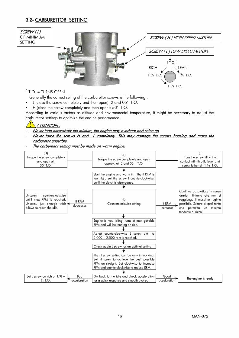
3.2- CARBURETTOR SETTING 1 T.O.*
RICH LEAN
1 ¼ T.O. ¾ T.O.
1 ½ T.O. * T.O. = TURNS OPEN Generally the correct settng of the carburettor screws is the following : � L (close the screw completely and then open): 2 and 05' T.O. � H (close the screw completely and then open): 50' T.O. According to various factors as altitude and environmental temperature, it might be necessary to adjust the carburettor settings to optimize the engine performance.
ATTENTION : - Never lean excessively the mixture, the engine may overheat and seize up - Never force the screws H and L completely. This may damage the screws housing and make the
carburetor unusable. - The carburettor setting must be made on warm engine.
(H) Torque the screw completely
and open at: 50' T.O.
(L)
Torque the screw completely and open approx. at 2 and 05' T.O.
(I) Turn the screw till to the
contact with throttle lever and screw futher of 1 ½ T.O.
Start the engine and warm it. If the if RPM is
too high, set the screw l counterclockwise, untill the clutch is disengaged.
If RPM decreases
Unscrew counterclockwise untill max RPM is reached. Unscrew just enough wich allows to reach the idle.
(L) Counterclockwise setting
If RPM increases
Continue ad avvitare in senso orario fintanto che non si raggiunge il massimo regime possibile. Svitare di quel tanto che permetta un minimo tendente al ricco.
Engine is now idling, turns at max gettable
RPM and will be tending on rich.
Adjust counterclockwise L screw until to
2.000 ÷ 2.500 rpm is reached.
Check again L screw for an optimal setting The H screw setting can be only in working.
Set H screw to achieve the besT possible RPM on straight. Set clockwise to increase RPM and counterclockwise to reduce RPM.
Set L screw on rich of 1/8 ÷
¼ T.O. Bad
acceleration Go back to the idle and check acceleration for a quick response and smooth pick-up.
Good acceleration The engine is ready
SCREW ( I ) OF MINIMUM SETTING
SCREW ( L ) LOW SPEED MIXTURE
SCREW ( H ) HIGH SPEED MIXTURE MMMIXTURESCREW

MAN-072 17
3.3- STARTING AND STOPPING THE ENGINE
The engine start is achieved by pushing the black rubber button on the bracket. If the engine does not start, stop and try again. If the engine does not start within 5 seconds (check that gasoline flows to the carburettor), stop the procedure and try after about 15 seconds. Short and frequent tries are better than long ones. In case the engine can't be started, refer to the Sec. 4.6 "Troubleshooting”. Stop the engine by pressing the red button on the bracket. Keep the stop button pressed until the engine is completely stopped.
3.4- ENGINE RUNNING-IN
The running-in must be made following a few basic rules : 1. Carburation setting. Start with basic setting on the rich side.
2. Warm the engine gradually for 5 minutes, driving some laps at low speed, smoothly
closing and opening the accelerator (if a tachometer is installed, never exceed 9.000 ÷ 10.000 RPM). Never keep the same RPM for a long time but alternate the speed.
3. Gradually increase the vehicle speed for about 5 minutes (with ¾ throttle opening). Never keep the same RPM for a long time but to alternate it.
4. Increase the speed driving some laps, for about 5 minutes (with acceleretor fully opened on circuit twisty parts and enrich the carburation at half straight (cover with the hand the inlet hole on the intake silencer for an istant, keeping the throttle open).
WARNING : Once the running-in is over, with cold engine, check the torque of exhaust pipe nuts as
during the 1st running-in, the nuts can loosen (refer to the attached table).
3.5- INLET SILENCER
Make sure that the inlet holes of the inlet silencer are towards the upper side and they are not covered. Make sure that the fixing strapis not loosen and that the inlet silencer is well fastened to the chassis through the specific strap.
Occasionally, check the presence of oil deposits in the inlet silencer. If necessary, remove the manifold with filter and clean the inside with gasoline or a diluent.
3.6- EXHAUST SYSTEM WARNINGS Make sure that the silencer fixing springs are well hooked. In case of damage replace the broken springs. Never race the kart without the two spring well hooked, as the silencer could vibrate under the standard limits. It is recommended to open the exhaust pipe end every 10 y15 hours and make sure that the holes on the counter cone are not obstructed by incrustation.
MAN-072 18
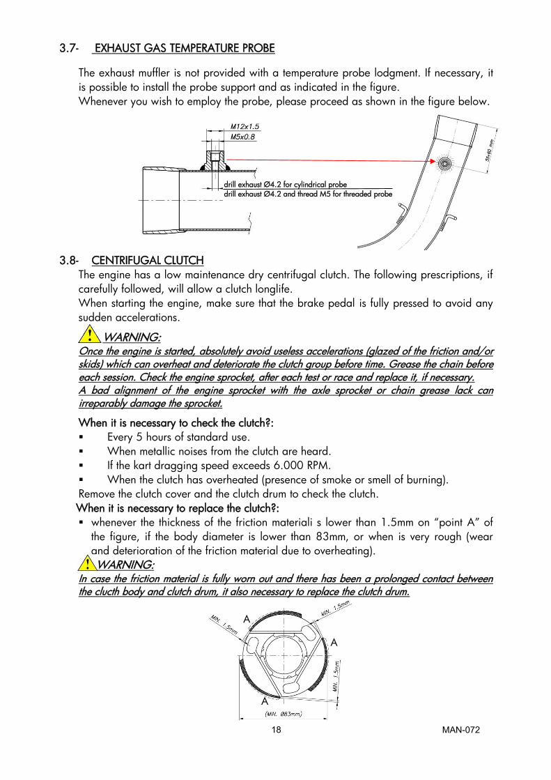
3.7- EXHAUST GAS TEMPERATURE PROBE
The exhaust muffler is not provided with a temperature probe lodgment. If necessary, it is possible to install the probe support and as indicated in the figure. Whenever you wish to employ the probe, please proceed as shown in the figure below.
3.8- CENTRIFUGAL CLUTCH
The engine has a low maintenance dry centrifugal clutch. The following prescriptions, if carefully followed, will allow a clutch longlife. When starting the engine, make sure that the brake pedal is fully pressed to avoid any sudden accelerations.
WARNING: Once the engine is started, absolutely avoid useless accelerations (glazed of the friction and/or skids) which can overheat and deteriorate the clutch group before time. Grease the chain before each session. Check the engine sprocket, after each test or race and replace it, if necessary. A bad alignment of the engine sprocket with the axle sprocket or chain grease lack can irreparably damage the sprocket.
When it is necessary to check the clutch?: � Every 5 hours of standard use. � When metallic noises from the clutch are heard. � If the kart dragging speed exceeds 6.000 RPM. � When the clutch has overheated (presence of smoke or smell of burning). Remove the clutch cover and the clutch drum to check the clutch.
When it is necessary to replace the clutch?: � whenever the thickness of the friction materiali s lower than 1.5mm on “point A” of
the figure, if the body diameter is lower than 83mm, or when is very rough (wear and deterioration of the friction material due to overheating).
WARNING: In case the friction material is fully worn out and there has been a prolonged contact between the clucth body and clutch drum, it also necessary to replace the clutch drum.
A
A
A
drill exhaust Ø4.2 for cylindrical probe drill exhaust Ø4.2 and thread M5 for threaded probe

MAN-072 19
3.9- INSTRUCTIONS FOR THE DISASSEMBLY / ASSEMBLY OF THE CLUTCH GROUP
WARNING : The following operations can be made by a skilled mechanic, with the proper tools shown in the text ; otherwise, it is necessaty to apply to an Authorized Service Center.
Refer to the following drawing during the different operations.
OPERATIONS TOOLS
Clutch disassembly 1. Remove the clutch cover (3 screws TCEI M6).
� Allen wrench 5mm – T type
2. Remove the bendix cover and place the starter wheel locking tool.
� Starter wheel locking tool : S 884
3. Remove the retainer nut (1 nut M10). � Ring wrench 17 mm
4. Remove the external washer, the complete drum with roller cage, the internal washer.
5. With the starter wheel locking tool in place, remove the 20x1clutch hub nut.
WARNING: unscrew clockwise as the nut has left-hand thread
� Starter wheel locking tool: S 884 � Allen wrench 30 mm
6. Remove the clutch hub and the starter wheel from the crankshaft through clutch puller.
� Clutch puller : ATT.026 � Allen wrench 12mm
7. Remove the starter wheel (3 screws M6 TCEI) � Allen wrench 5mm – T type
1 Drum retaining nut 6 Sprocket 11 Clutch body 2 External washer 7 Clutch drum 12 Starter wheel 3 Roller cage 8 Internal washer 4 O Ring 9 Loocking nut 5 Screw 10 Screw
1 2 3 4
6
7
10
8
5
9
11
12

MAN-072 20
Before assembling the clutch, wash with the diluent : the shaft cone, the starter wheel and the clutch drum.
Clutch assembly
1. Asseble the starter wheel on the clutch hub by matching the 3 holes and the dragging pin
2. (3 screws TCEI M6) WARNING: it is necessary to always install the Ø 7
mm pin, as eventual kicks could shear the screws.
� Allen wrench 5mm – T type (torque at 10÷12 Nm)
� Apply “Loctite” threadlocker
2. Place the clutch hub and the starter wheel on the shaft.
� Apply “Loctite 641” for coaxial locking.
3. Assemble the fixing nut, clutch hub and starter wheel, through the starter wheel locking tool and the allen wrench 30mm. WARNING: Screw clockwise as the nut has left-hand thread.
� Starter wheel locking tool : S 884 � Allen wrench 30 mm. (torque at 100 ÷ 110 Nm)
4. Assemble the internal washer.
WARNING: the bevel of the washer hole must be towards the shaft.
Clean the roller cage and grease it before assembling it on the shaft.
5. Mount the clutch drum and the external washer.
WARNING: the bevel of the washer hole must be towards the shaft.
6. With the starter wheel locking tool in place, tighten the drum retainer nut (nut M10).
� Starter wheel locking tool: S 884 � Ring wrench 17 mm (torque at 30 ÷ 40 Nm)
7. Reassemble the clutch cover (3 screws TCEI M6) � Allen wrench 5mm – T type (torque at 8 ÷ 10 Nm)
3.10 BATTERY
The battery (12V – 9Ah) is selaed and without maintenance. In order to prolong the battery life, it is recommended to follow these few prescriptions: � When the tension drops below 12.6V, it is necessary to recharge the battery. � The max allowed recharging current is 1.8A. � The ideal recharge is achieved with an average current of 0.8÷1A. (recharging time of approx 10 h.) at an environmental temperature between 0° e 40°C.
WARNING: An ovecharge or an extremely quick charge with excessive current can damage the battery components (battery swelling). Choose a battery charger with the following characteristics : � Feeding tension : 90/250 Vac – 50/60 Hz � Outlet tension : 15 V full charge – 13.8 stand-by � Max outlet current : 2A full charge � During the transport and/or the storage, the battery could loose part of its charge due to the self-discharge (0.1% max. per day). Fully charge the battery before use.
WARNING: Always connect the + (positive) pole before the - (negative) pole. Always disconnect the battery in opposite order.
� Recharge the battery at least once every 6 months

MAN-072 21
� Never let the battery tension drop under 8V as under this limit the battery can not be used and it will have to be replaced.
� Never put the battery in contact with solvents, oils, plastifiers or rags containing such elements as the battery external case could be damaged.
� Never press and/or bend or overheat the battery terminals (for ex. by welding).
Other recommendations � Avoid the generation of sparks or flames upun or around the battery. � Never short-circuit the terminals. � Never open the battery or throw in the fire � In case the electrolyte (diluted Sulfuric Acid) gets in contact with skin or clothes,
wash immediately with water. In case it gets in touch with eyes, wash and apply for medical assistance.
� Carefully check the external battery case and replace it in case of damages, swellings of the case or the battery cover.
� Before use, clean the battery from dust or other dirt and check that the poles are not oxydized or damaged.
� At the end of the battery life, never throw it in the garbage but deliver it to an authorized waste disposer.
3.11- SPARK PLUG AND THERMAL DEGREE
The engine is supplied with a standard NGK BR10EG spark plug. It represents a good compromise between the need of a good running-in and the racing needs in standard conditions. The use of different spark plugs is possible and, as a general information, we are attaching a correspondence list among several brands, according to the thermal degree which represents the capacity of the spark plug to dissipate the inside heat. The colour of the various parts of the spark plug more exposed to the combustion flames gives a good indication of the suitability of the thermal degree and on the carburetion. It is necessary though to understand which of the two parameters has to be modified and only tells how to identify the spark plug with a most suitable thermal degree, as lean or rich mixtures can generate the same final look which can also be achived with spark plugs respectively too hot or too cold. See the table for information purposes : A spark plug too hot shows the symptoms aside listed. WARNING: employ a spark plug too hot than a standard one, with cold or rainy weather.
� Extremely clear colour, porous and calcified look of the electrodes and of the internal insulation.
� Ignition irregularity, preignition and detonation with tendency to perforate the top of the piston.
� Note: some of these symptoms can be achieved with lean mixtures.
A spark plug with suitable thermal degree shows :
� Shade colour, from the insulator end and of the electrode, from yellow grey till to dark brown for mixture respectively lean or rich.
A spark plug too cold shows the symptoms aside listed.
WARNING: employ a spark plug too cold than a standard one, with very hot weather
� Insulator end and elctrodes covered byblack matt soot � Ignition difficulties. � Note: a wet or oily electrode could also mean a too
rich misture

MAN-072 22
INDICATIVE SPARK PLUG COMPARISON TABLE
BASED ON THERMAL DEGREE
HOT
BOSCH NGK CHAMPION WO8CS BR9EG N54R WO7CS BR10EG N52R WO6CS BR11EG
COLD 3.12- CHOICE OF THE SPROCKETS RATIO
The life of an engine depends upon many factors but most of all upon the speed at which the engine is operated. If an engine is normally operated at speeds higher than what recommended by the manufacturer, the wear and stress of the different components (con-rods, roller cages, bearings etc.) will be such as to drastically reduce the life of the engine itself. It is therefore extremely important that the user respects the operating limits imposed by the manufacturer.
The operating limit for the Reedjet 100cc AUS engine is 15.000 RPM.
ATTENTION:
Never exceed the above limit. No obligation of IAME exists in case the above limit is
exceed.
In case the user wishes to optimize the sprocket ratio on the track, in order to achieve the best possible performance and without overloading the engine, follow the under shown recommendations.
The engines are supplied with a 10,11,12 or 13 teeth sprocket (pitch: 7.775mm). Table 1 shows the various ratios between the sprocket on the axle and the engine sprocket given the different axle sprockets.
Tab.1
Sprocket Ratio Teeth n° - Engine sprocket Sprocket Ratio Teeth n° - Engine sprocket
Starting Gear 10 11 12 13 Teeth n° Axle Gear 10 11 12 13
72 7,2 6,55 6,00 5,54 83 8,3 7,55 6,92 6,38 73 7,3 6,64 6,08 5,62 84 8,4 7,64 7,00 6,46 74 7,4 6,73 6,17 5,69 85 8,5 7,73 7,08 6,54 75 7,5 6,82 6,25 5,77 86 8,6 7,82 7,17 6,62 76 7,6 6,91 6,33 5,85 87 8,7 7,91 7,25 6,69 77 7,7 7,00 6,42 5,92 88 8,8 8,00 7,33 6,77 78 7,8 7,09 6,50 6,00 89 8,9 8,09 7,42 6,85 79 7,9 7,18 6,58 6,08 90 9 8,18 7,50 6,92 80 8 7,27 6,67 6,15 91 9,1 8,27 7,58 7,00 81 8,1 7,36 6,75 6,23 92 9,2 8,36 7,67 7,08 82 8,2 7,45 6,83 6,31

MAN-072 24
3.13- REPLACEMENT OF THE STARTER BRUSHES
OPERATIONS PICTURES
DISASSEMBLE THE STARTER MOTOR
- LOOSE THE SCREW M6X30 ON THE
ADDITIONAL STARTER SUPPORT
(See Fig.1).
(5mm ALLEN WRENCH T TYPE)
- REMOVE THE ADDITIONAL STARTER SUPPORT
3 SCREWS M6X25 (See Fig.2).
(5mm ALLEN WRENCH T TYPE)
- REMOVE THE STARTER SUPPORT
4 SCREWS M6x35
(See Fig.3).
(5mm ALLEN WRENCH T TYPE)
- LOOSE THE 3 SCREWS M6x35 TO REMOVE
THE STARTER (See Fig.4).
(5mm ALLEN T TYPE)
- EXTRACT THE STARTER MOTOR
(See Fig.5).
Fig.1
Fig.2
Fig.3
Fig.4
Fig.5

MAN-072 25
OPENING THE STARTER MOTOR
- UNSCREW THE M4 SCREW FIXING THE INPUT
CABLE
(See Fig.6)
(SCREWDRIVER)
- UNSCREW THE 3 M5 “C” SCREWS (See Fig.7)
(SCREWDRIVER)
Fig.1 Fig.6
Fig.7
MAN-072 26
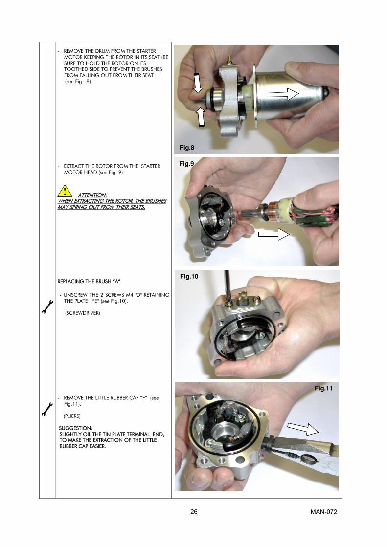
- REMOVE THE DRUM FROM THE STARTER
MOTOR KEEPING THE ROTOR IN ITS SEAT (BE
SURE TO HOLD THE ROTOR ON ITS
TOOTHED SIDE TO PREVENT THE BRUSHES
FROM FALLING OUT FROM THEIR SEAT
(see Fig . 8)
- EXTRACT THE ROTOR FROM THE STARTER
MOTOR HEAD (see Fig. 9)
ATTENTION:
WHEN EXTRACTING THE ROTOR, THE BRUSHES
MAY SPRING OUT FROM THEIR SEATS.
REPLACING THE BRUSH “A”
- UNSCREW THE 2 SCREWS M4 "D" RETAINING
THE PLATE “E” (see Fig.10).
(SCREWDRIVER)
- REMOVE THE LITTLE RUBBER CAP “F” (see Fig.11).
(PLIERS)
SUGGESTION:
SLIGHTLY OIL THE TIN PLATE TERMINAL END,
TO MAKE THE EXTRACTION OF THE LITTLE
RUBBER CAP EASIER.
Fig.4
Fig.8
Fig.9
Fig.10
Fig.11

MAN-072 27
- REMOVE THE SILICON FROM BRUSHES WITH A
SCREWDRIVER (see Fig. 11)
- REMOVE SPRINGS
- REMOVE THE BRUSH MAKING PRESSURE ON
THE TIN PLATE TERMINAL EXTERNALLY
(see Fig. 13)
- INSTALL NEW BRUSH TERMINAL
(See Fig.14).
- PLACE THE LITTLE RUBBER CAP ON THE
TERMINAL.
- REINSTALL THE PLATE AND FIX IT
WITH THE 2 SCREWS M4
(See Fig.15).
(SCREWDRIVER)
Fig.9
Fig.12
Fig.13
Fig.14
Fig.15

MAN-072 28
REPLACEMENT OF THE BRUSH “B”
- LOOSE THE SCREW M3 “G” (See Fig.16)
- EXTRACT THE BRUSH
- FIX THE NEW BRUSH WITH SCREW M6
(SCREWDRIVER)
CLOSING THE STARTER
- INSERT THE NEW BRUSH SPRING "A" INTO
ITS SEAT.
- INSTALL THE BRUSH.
- KEEP THE BRUSH IN PLACE BY PRESSING
TOWARDS THE OUTER AND CLAMP IT WITH
AN IRON WIRE BENT AS A HOOK.
REPEAT THE SAME PROCEDURE TO INSTALL
THE BRUSH "B" (See Fig.17).
- INSTALL THE ROTOR BETWEEN THE BRUSHES
AND CHECK THAT THEY ARE ALWAYS IN
CONTACT WITH THE CYLINDRIC COPPER
PART OF THE ROTOR, EVEN WHEN THEY ARE
RELEASED. (See Fig.18).
SUGGESTION:
TO IMPROVE THE BRUSHES LIFE, SECURE THE
LITTLE WIRES WITH SILICONE (See Fig.19).
Fig.16
Fig.17
Fig.18
Fig.19
MAN-072 29
5
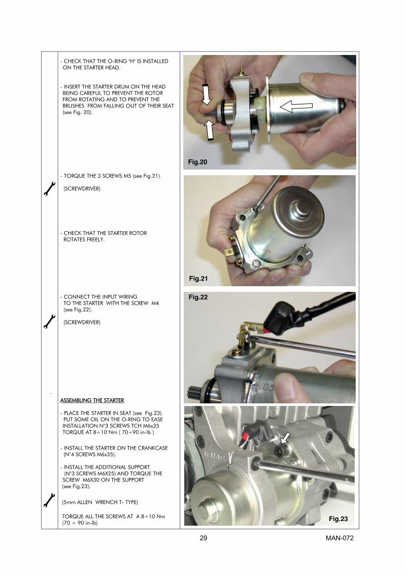
- CHECK THAT THE O-RING "H" IS INSTALLED
ON THE STARTER HEAD.
- INSERT THE STARTER DRUM ON THE HEAD
BEING CAREFUL TO PREVENT THE ROTOR
FROM ROTATING AND TO PREVENT THE
BRUSHES FROM FALLING OUT OF THEIR SEAT
(see Fig. 20).
- TORQUE THE 3 SCREWS M5 (see Fig.21).
(SCREWDRIVER)
- CHECK THAT THE STARTER ROTOR
ROTATES FREELY.
- CONNECT THE INPUT WIRING
TO THE STARTER WITH THE SCREW M4
(see Fig.22).
(SCREWDRIVER)
ASSEMBLING THE STARTER
- PLACE THE STARTER IN SEAT (see Fig.23).
PUT SOME OIL ON THE O-RING TO EASE
INSTALLATION N°3 SCREWS TCH M6x35
TORQUE AT 8÷10 Nm ( 70÷90 in-lb )
- INSTALL THE STARTER ON THE CRANKCASE
(N°4 SCREWS M6x35).
- INSTALL THE ADDITIONAL SUPPORT
(N°3 SCREWS M6X25) AND TORQUE THE
SCREW M6X30 ON THE SUPPORT
(see Fig.23).
(5mm ALLEN WRENCH T- TYPE)
TORQUE ALL THE SCREWS AT A 8÷10 Nm
(70 ÷ 90 in-lb)
Fig.20
Fig.21
Fig.22
Fig.23

MAN-072 30
3.14- SCHEDULE MAINTENANCE
Following some simple maintenance standards will allow the engine to perform more reliably and have a longer life.
SCHEDULE COMPONENTS ACTIONS AND COMMENTS
Before each use Flexible spring Check status
Muffler Check status and fixing (springs)
Engine sprocket Check wear
Check alignment with axle
sprocket
Engine chain Check wear, tensioning and
chain lubrication
Battery Check status and charge
Cables and connectors Check status and restore the
connections
Grounding engine Check status and restore the
connections
Battery support, bracket and
clamps
Check torques
After each use Battery Disconnect
Chain Lubrification
Engine External cleaning
every 5 ÷ 10 hours Bendix starter Remove cover (see fig.) and
clean internally.
Exhaust muffler Remove muffler end, clean
Intake silencer Open , clean
Engine head Open , clean
Clutch Open, check status of parts and
if necessary replace part.
Every 20 hours Piston and con-rod assembly Replace worn parts
Crankshaft Replace worn parts
Main bearings Replace worn parts

MAN-072 31
3.15- TROUBLESHOOTING
Here below there are some of the most common problems, the possible causes and the
recommended solutions to solve them.
PROBLEMS PROBABLE CAUSES SOLUTIONS
Starter will not crank when pushing
the start button
Bad connections on starter cables Check connections and tighten
Bad grounding Check connections and tighten
Damaged cables Replace them
Battery connection loose Check and tighten connections
Battery discharged Recharge or replace battery
Damaged starter Check
Starter cranks but engine won't start Bad cable connections Check that connectors are properly
connected.
Bad H.T. Coil connections or coil
failure
Check/replace
Bad H.T. coil grounding Check grounding
Wet spark plug Replace
Malfunction on induction system Check status and connection on
fuel pipe
Replace mambranes and gaskets
on carburettor
Pushing the start button, the engine
starts but turns off after a short
time.
Bad harness connections Check connectors
Bad carburettor setting (screw I) Check carburettor retting
(see sect. 5)
The starter turns also after
releasing the start button.
Battery not sufficiently charged
(sticking of the starter relay)
Remove the positive pole of the
battery to stop the engine and
recharge the battery.
The engine stops at minimum Bad setting of idle screw on
carburettor ( screw L)
Check carburettor retting
(see sect. 5)
The engine shows a performance
drop
Bad compression Check piston status
Bad carburettor setting Check carburettor retting
(see sect. 5)
Insufficient power system Check fuel flow and inlet filter.
Blocked intake silencer Check and clean
Burning smell, presence of smoke Clutch overheating Check the clutch status
(see sect. 11)
Clutch engages at too high RPM Excessive wear of the friction
material
Check the clutch status
(see sect. 11)
Too much noise coming from the
exhaust system
Damaged flexible Check and replace if necessary
Damaged or lost springs
Damaged or lost insulating tape
Damaged exhaust pipe

MAN-072 35
3.19- ENGINE AND ACCESSORIES PRESERVATION
When the engine is not operating for a long period, it must be preserved in the most
suitable way:
� Disconnect the battery and recharge it regularly (see sect. 12)
� Disassemble the carburettor and clean it
� Seal the inlet and the exhaust with adhesive paper
External parts must be cleaned and steel parts, subject to oxidation, protected with light film
oil. Keep the engine in a dry place.
3.20- TORQUE VALUES
NOMINAL SIZE Q.TY FASTENER NAME WRENCH VALUES (Nm)
M14x1,25 1 Spark Plug Hex.20,8 20 ÷ 26
M8x1,25 5 Head and Cylinder Nuts Hex.13 18 ÷ 22
M8x1,25 2 Exhaust manifold Stud Nuts Hex.13 18 ÷ 22
M6x1 4 Reed Group Screws Allen 5 8 ÷ 10
M5x0,8 3 Coil Attack Screws Allen 4 5 ÷ 6
M5x0,8 2 Ignition Stator Fixing Screws Allen 4 5 ÷ 6
M10x1 1 Ignition Rotor Fixing Nuts Hex.17 20 ÷ 26
M6x1 3 "Bendix" Support Cover Screws Allen 5 6 ÷ 8
M6x1 4 "Bendix" Support Screws Allen 5 6 ÷ 8
M6x1 4 Starter Support Fixing Screws Allen 5 8 ÷ 10
M6x1 3 Clutch Cover Fixing Screws Allen 5 8 ÷ 10
M10x1 1 Clutch Drum Fixing Nut Hex.17 30 ÷ 40
M20x1 1 Starter Ring Fixing Nut Hex.30 100 ÷ 110
M5x0,8 4 Engine Sprocket Fixing Screws Allen 3 6 ÷ 8
M6x1 3 Starter Ring Fixing Screws Allen 5 10 ÷ 12
M6x1 8 Crankcase Fixing Screws Allen 5 8 ÷ 10
MAN
-072 36
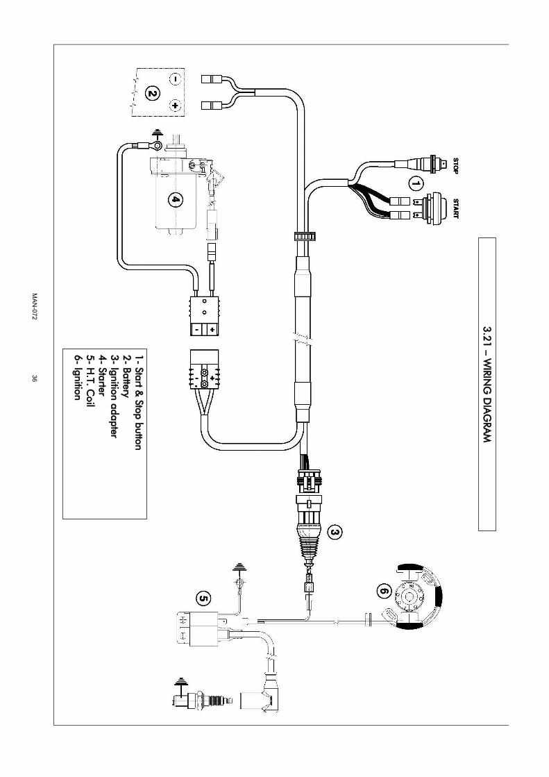
1
- Start &
Stop button
2- Battery
3- Ignition adapter
4- Starter
5- H
.T. C
oil
6- Ignition
3.2
1 –
W
IRIN
G D
IA
GRA
M