Redwood Bridge – Rehabilitative Maintenance and Related Works
14
1 Redwood Bridge – Rehabilitative Maintenance and Related Works Mike Lau, Ph.D., P.Eng., UMA Engineering Ltd. (Presenter) Barry Biswanger, P.Eng., UMA Engineering Ltd. Bill Ebenspanger, P.Eng., City of Winnipeg Paper prepared for presentation at the Bridges – Economic and Social Linkages (B) Session of the 2007 Annual Conference of the Transportation Association of Canada Saskatoon, Saskatchewan
Transcript of Redwood Bridge – Rehabilitative Maintenance and Related Works

1
Redwood Bridge – Rehabilitative Maintenance and Related Works
Mike Lau, Ph.D., P.Eng., UMA Engineering Ltd. (Presenter) Barry Biswanger, P.Eng., UMA Engineering Ltd.
Bill Ebenspanger, P.Eng., City of Winnipeg
Paper prepared for presentation
at the Bridges – Economic and Social Linkages (B) Session
of the 2007 Annual Conference of the Transportation Association of Canada
Saskatoon, Saskatchewan
2
ABSTRACT The Redwood Bridge is the oldest remaining as-constructed bridge in the City of Winnipeg. Originally built in 1908 for streetcars and wagon traffic, it provided a vital link between two distinct communities and continues to do so this day, as demonstrated by the approximately 25,000 vehicles that use the bridge on a daily basis. Rehabilitating this historic structure ensures it is able to provide service well into the future, supports the social and economic development of the communities on both sides of the river and provides an important transportation link to the City of Winnipeg. As expected for a structure that is nearly 100 years old, the bridge was showing its age. The foundations had shifted and the steel beams and trusses that carried the loads had deteriorated, partly due to corrosion from the road salt necessary for safe winter driving. Rehabilitating the bridge at this time prevented further deterioration and avoided much more costly work and lengthy unscheduled closures in the future. This paper describes all the rehabilitative maintenance work, including concrete pier jacketing, pier cap reconstruction, replacement of bearings, deteriorated structural steel components, sidewalks and corrosion protection of steel through trusses by applying zinc metallizing to all steel surfaces. The General Contractor for this project was MD Steele Construction Limited based in Winnipeg. The total cost of the rehabilitative maintenance and related work of this project was $9.6M. INTRODUCTION The original Redwood Bridge was a two-lane, five-span bridge which consisted of a 45.7-m simple span steel through truss at each end, a 77.6-m swing span steel through truss, and a 29.1-m long simple span steel through truss, with a total length of 198.1 m. It had a clear roadway width of 7200 mm and a 1900 mm wide sidewalk on each side of the bridge. Figure 1 shows the elevation and section of the bridge. The foundation consisted of four reinforced concrete piers and two reinforced concrete abutments supported on timber piles. As expected for a structure that is nearly 100 years old, the bridge was showing its age. The bridge’s foundations had shifted and the steel beams and trusses that carried the loads had deteriorated, partly due to corrosion from the road salt necessary for safe winter driving. Rehabilitating the bridge at this time will prevented further deterioration and avoided much more costly work and lengthy unscheduled closures in the future.

3
4
SCOPE OF WORK After nearly 100 years of service, the bridge required rehabilitation in a number of areas. In 2002, the City of Winnipeg retain UMA Engineering Ltd. to provide preliminary and detailed design and contract administration services for the rehabilitative maintenance and related works for this bridge. The rehabilitation works were identified as follows:
1. Jacketing concrete piers
2. Reconstructing pier caps
3. Replacing expansion joints and bearings
4. Replacing deteriorated structural steel components
5. Replacing concrete deck and timber sidewalks
6. Replacing pedestrian rails
7. Installing vehicular safety rails
8. Removing knee braces at the through truss portals
9. Corrosion protecting steel through trusses by applying zinc metallizing to all steel surfaces.
CONCRETE PIERS AND PIER CAPS All the piers in the river were in poor condition. Both the concrete and ice breaker were deteriorated. A minimum 150 mm of deteriorated concrete was removed from the pier. All of the piers were encased with a minimum of 300 mm thick reinforced concrete that was poured on the pier surface. 15M dowels, spaced at 300 mm on centre were installed on the pier surface to make sure that the new concrete would adhere to the existing pier. With the removal of existing bearings, drive gears and shafts of the existing swing span through truss, extensive modifications to the pier caps were carried out. Cast-in-place reinforced concrete pedestals were installed on the pier caps so that the new bearings could be installed properly.
5
Jacking the four pier shafts and reconstructing three pier caps needed to be completed between the low draw down of the Red River (usually in late October or early November) and spring run off (late March or early April). All the following construction activities had to be completed within this time frame:
• Installing temporary work platforms (to capture demolition and construction debris)
• Removing deteriorated concrete • Installing dowels • Reinforcing cage • Installing concrete forms work • Pouring and curing concrete encasement.
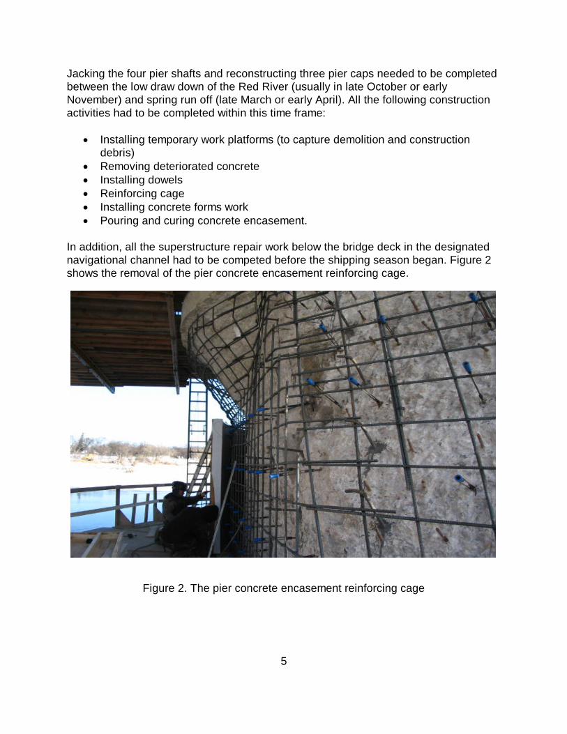
In addition, all the superstructure repair work below the bridge deck in the designated navigational channel had to be competed before the shipping season began. Figure 2 shows the removal of the pier concrete encasement reinforcing cage.
Figure 2. The pier concrete encasement reinforcing cage
6
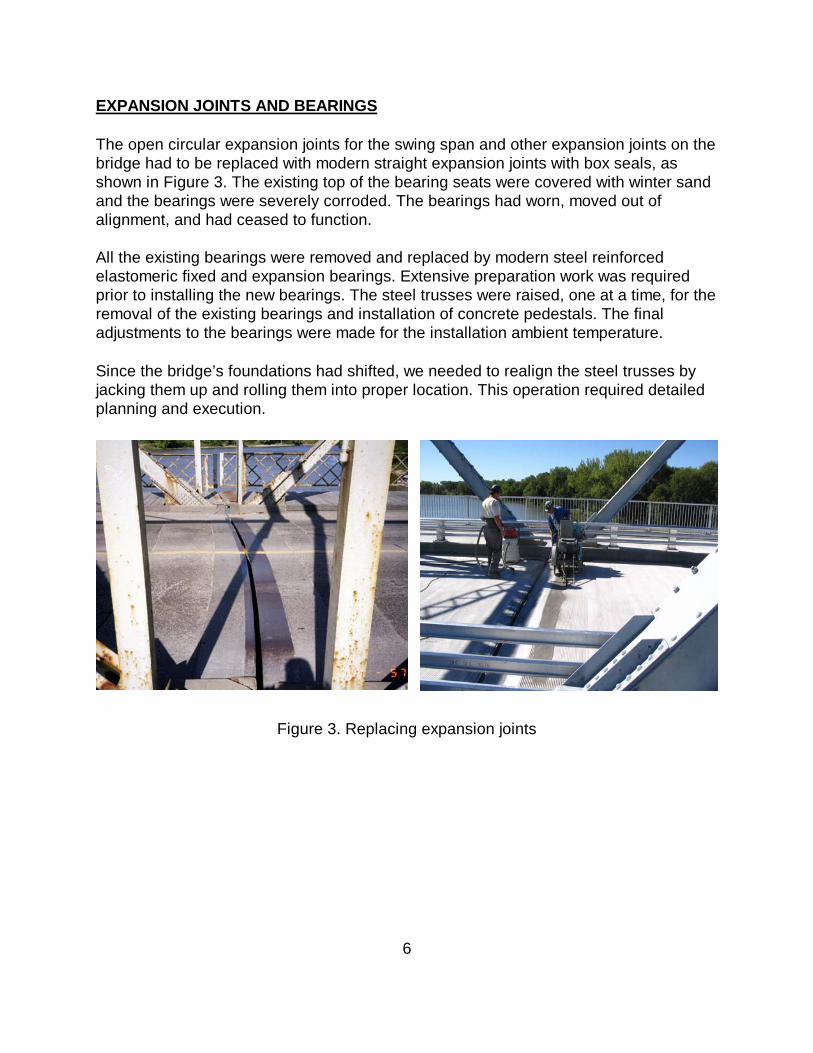
EXPANSION JOINTS AND BEARINGS The open circular expansion joints for the swing span and other expansion joints on the bridge had to be replaced with modern straight expansion joints with box seals, as shown in Figure 3. The existing top of the bearing seats were covered with winter sand and the bearings were severely corroded. The bearings had worn, moved out of alignment, and had ceased to function. All the existing bearings were removed and replaced by modern steel reinforced elastomeric fixed and expansion bearings. Extensive preparation work was required prior to installing the new bearings. The steel trusses were raised, one at a time, for the removal of the existing bearings and installation of concrete pedestals. The final adjustments to the bearings were made for the installation ambient temperature. Since the bridge’s foundations had shifted, we needed to realign the steel trusses by jacking them up and rolling them into proper location. This operation required detailed planning and execution.
Figure 3. Replacing expansion joints

7
DETERIORATED STRUCTURAL COMPONENTS The main floor beams and some of the stringers that framed into the floor beams at the open expansion joints were severely corroded and required replacement and/or repair. The existing floor beams were made up of back-to-back angles at top and bottom and riveted to the web plate. W-section with similar height and sectional properties were used to replace the existing floor beams. Any cracked and severely corroded stringers in these areas were either repaired or replaced. Significant corrosion and section loss occurred at the bottom of the vertical members of the through truss. These members were fabricated from back-to-back channels. All these deteriorated sections were removed and replaced by similar sections. Figure 4 shows a sample of the deteriorated steel structural component.
Figure 4. Bottom truss vertical member rusted through
8
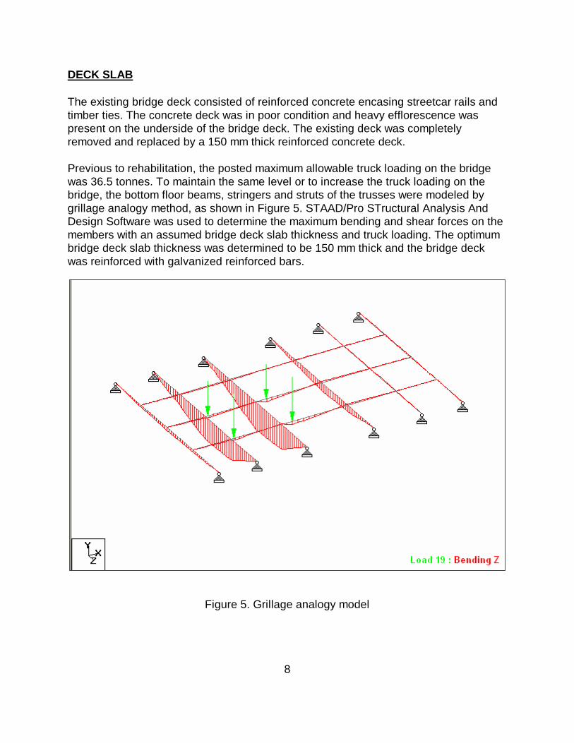
DECK SLAB The existing bridge deck consisted of reinforced concrete encasing streetcar rails and timber ties. The concrete deck was in poor condition and heavy efflorescence was present on the underside of the bridge deck. The existing deck was completely removed and replaced by a 150 mm thick reinforced concrete deck. Previous to rehabilitation, the posted maximum allowable truck loading on the bridge was 36.5 tonnes. To maintain the same level or to increase the truck loading on the bridge, the bottom floor beams, stringers and struts of the trusses were modeled by grillage analogy method, as shown in Figure 5. STAAD/Pro STructural Analysis And Design Software was used to determine the maximum bending and shear forces on the members with an assumed bridge deck slab thickness and truck loading. The optimum bridge deck slab thickness was determined to be 150 mm thick and the bridge deck was reinforced with galvanized reinforced bars.
Figure 5. Grillage analogy model
9
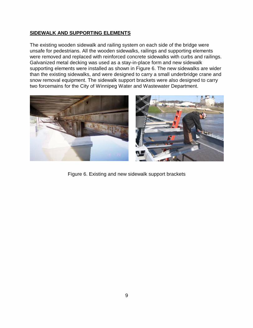
SIDEWALK AND SUPPORTING ELEMENTS The existing wooden sidewalk and railing system on each side of the bridge were unsafe for pedestrians. All the wooden sidewalks, railings and supporting elements were removed and replaced with reinforced concrete sidewalks with curbs and railings. Galvanized metal decking was used as a stay-in-place form and new sidewalk supporting elements were installed as shown in Figure 6. The new sidewalks are wider than the existing sidewalks, and were designed to carry a small underbridge crane and snow removal equipment. The sidewalk support brackets were also designed to carry two forcemains for the City of Winnipeg Water and Wastewater Department.
Figure 6. Existing and new sidewalk support brackets

10
BRIDGE TRAFFIC RAILING, APPROACH ROADWAY AND GUARDRAIL The existing bridge did not have any railing system to prevent errant vehicles from hitting the vertical and diagonal members of the steel through trusses or pedestrians on the sidewalks. To improve the safety on the bridge, a bridge railing system was installed. It consisted of aluminium rails and posts as shown in Figure 7.
Figure 7. Bridge traffic railing system The existing roadway approach guardrail system had to be upgraded to the latest City of Winnipeg standard, which included the installation of the approach guardrails to safely channel the traffic onto and away from the bridge and approach roadway.

11
KNEE BRACES The portal frame knee braces of this bridge were damaged frequently by over-height trucks, which resulted in costly repairs. To prevent this from occurring, a structural analysis was carried out to determine whether or not the knee braces at the portal frame could be removed without any negative impact on the performance of the existing trusses. Three dimension models of the trusses were generated and subjected to various combinations of wind and truck loadings, as shown in Figure 8. Based on the analytical results, all the knee braces on the portal frames were removed and thereby minimized the over-height trucks hitting the trusses.
Figure 8. Three-dimensional analysis of a through truss
12
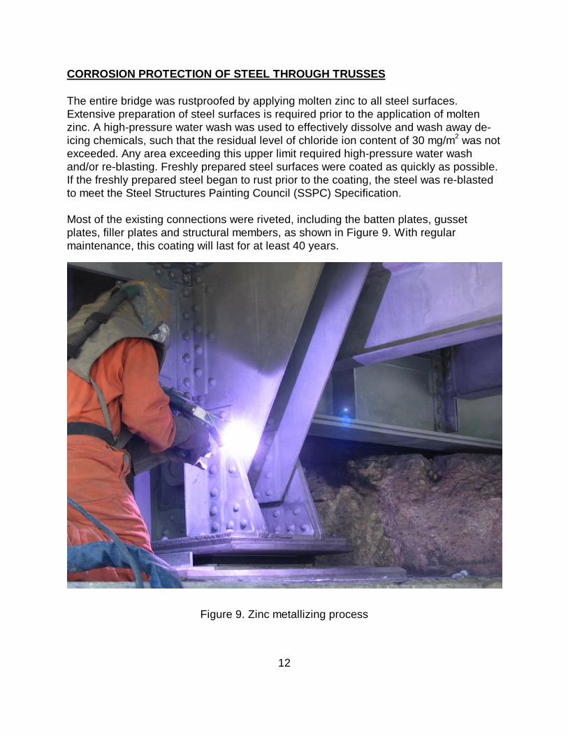
CORROSION PROTECTION OF STEEL THROUGH TRUSSES The entire bridge was rustproofed by applying molten zinc to all steel surfaces. Extensive preparation of steel surfaces is required prior to the application of molten zinc. A high-pressure water wash was used to effectively dissolve and wash away de-icing chemicals, such that the residual level of chloride ion content of 30 mg/m2 was not exceeded. Any area exceeding this upper limit required high-pressure water wash and/or re-blasting. Freshly prepared steel surfaces were coated as quickly as possible. If the freshly prepared steel began to rust prior to the coating, the steel was re-blasted to meet the Steel Structures Painting Council (SSPC) Specification. Most of the existing connections were riveted, including the batten plates, gusset plates, filler plates and structural members, as shown in Figure 9. With regular maintenance, this coating will last for at least 40 years.
Figure 9. Zinc metallizing process

13
ENVIRONMENTAL ISSUES UMA carried out a detailed environmental review prior to commencing the project. This exercise enabled us to identify all activities that could have adverse affects on the environment. Approximate mitigation measures were developed. For example, paint samples from the existing bridges were collected and analyzed for lead content. To avoid spreading containments from sandblasting activities, the components being sandblasted were completely enclosed, and waste was entirely recuperated for disposal in approved sites. Working platforms, the full width and length of spans, were installed to eliminate the possibility of debris such as rivets and bolts from being dropped into the river below. Short-term erosion and sediment control measures were installed to prevent soil laden runoff from entering the Red River and remained in place until vegetation was re-established. CONSTRUCTION SCHEDULE The first part of the project, from October 2005 to December 2005, did not require bridge closures. The work included repairing the concrete foundation both in the river and on land. Crews worked from land and from barges on the river. During the second part of the project, from January 2006 to September 2006, the bridge was closed to vehicles. This work included repairing and replacing the bridge structural steel components, replacing expansion joints, bearings, existing deck and sidewalk. While the original plan was to keep one sidewalk on the bridge open for pedestrians throughout the project, this was not possible due to the degree of the rehabilitation work required for the sidewalks and the need to maintain the construction schedule. The City provided regularly scheduled free shuttle service to move people from one side of the river to the other. The project was completed a month ahead of schedule due to extensive planning and innovative construction procedures. PROJECT COST Several tenders were received. The lowest tender was submitted by MD Steele Construction based in Winnipeg, Manitoba. The total cost for the rehabilitative and maintenance works was $9.6M. This translates to a unit cost of $4600.00 per square metre of the bridge deck.

14
CONCLUSIONS The rehabilitative and maintenance works of the Redwood Bridge involved:
• Jacketing concrete piers • Reconstructing pier caps • Replacing bearings • Replacing deteriorated structural steel components • Replacing concrete deck and timber sidewalks • Replacing pedestrian rails • Installing vehicular safety rails • Removing knee braces at the through truss portals • Corrosion protecting steel through trusses by applying zinc.
The project was completed a month ahead of the completion due to extensive planning and innovative construction procedures.


![The Redwood gazette. (Redwood Falls, Minn.), 1909-05-19, [p ].](https://static.fdocuments.us/doc/165x107/61f3066c4fb1c01f2e62eb08/the-redwood-gazette-redwood-falls-minn-1909-05-19-p-.jpg)