Redundant Grid Protection for Embedded Solar PV · PDF fileRedundant Grid Protection for ......
8
Written by Damian Jones Project Manager MV and Renewable Solutions Technical News Issue #71 - Summer 2014 nhp.com.au nhp-nz.com Industrial Electrical and Automation Products, Systems and Solutions Redundant Grid Protection for Embedded Solar PV Generators
Transcript of Redundant Grid Protection for Embedded Solar PV · PDF fileRedundant Grid Protection for ......
Written by Damian Jones Project Manager MV and Renewable Solutions
Technical News
Issue #71 - Summer 2014
nhp.com.au nhp-nz.com
Industrial Electrical and Automation Products, Systems and Solutions
Redundant Grid Protection for Embedded Solar PV Generators

NHP - technical news
2
Penetration of grid connected solar PV systems into the Australia residential market has been high. Small domestic systems with capacities of around 5kW or less are common. The impact of these systems on the electricity distribution gird has been minimal except in areas with exceptionally high installation rates. For example in parts of the state of Queensland 44% of domestic dwellings that are suitable for the installation of solar PV have had it installed (Reference 1).
NHP expects that continued increases in electricity prices and the growing awareness of the cost effectiveness of solar PV will make the installation of commercial/industrial scale systems with capacities of around 30kw to 500kW more widespread.
It is commonplace for systems of this size to attract additional scrutiny from the electricity network operator. They may require the system to include redundant grid protection measures in an effort to guarantee a certain level of safety and power quality within the distribution grid.
This Technical Newsletter discusses typical grid protection requirements from the network operators and presents a number of solutions for meeting these requirements. Firstly we will begin with a brief discussion of grid connected solar PV systems.
NHP - technical news
3
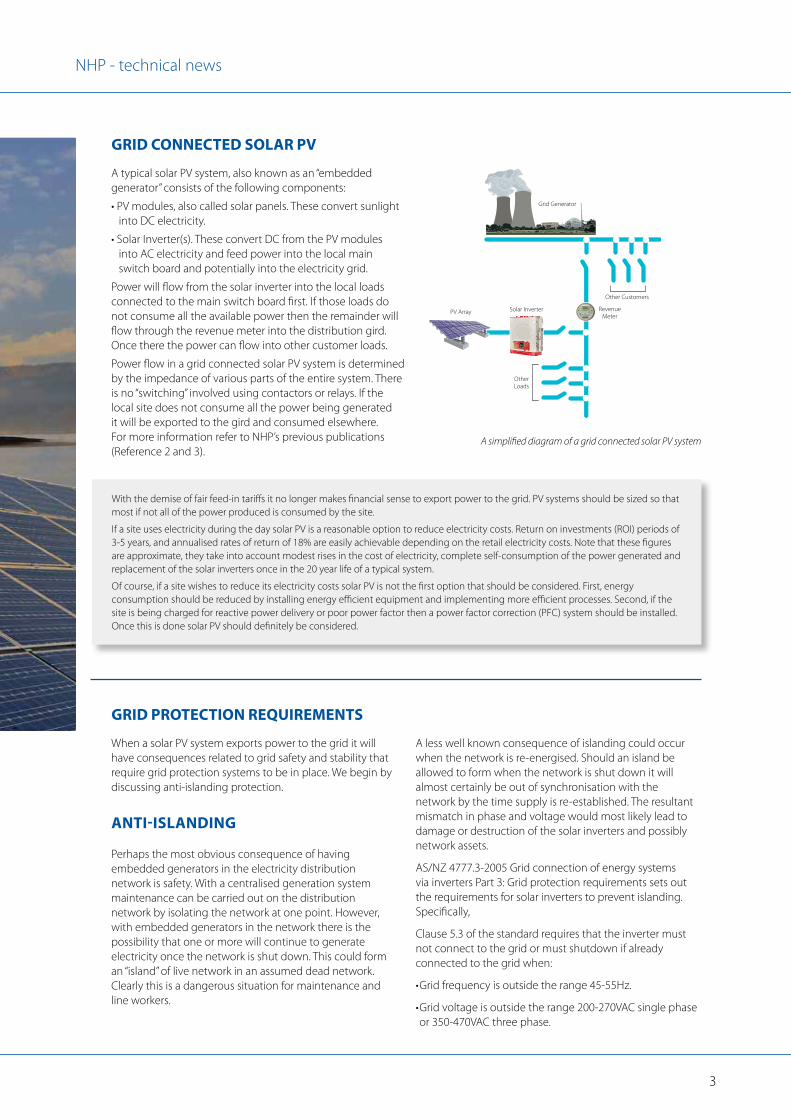
GRID CONNECTED SOLAR PV
GRID PROTECTION REQUIREMENTS
A typical solar PV system, also known as an “embedded generator” consists of the following components:
• PV modules, also called solar panels. These convert sunlight into DC electricity.
• Solar Inverter(s). These convert DC from the PV modules into AC electricity and feed power into the local main switch board and potentially into the electricity grid.
Power will flow from the solar inverter into the local loads connected to the main switch board first. If those loads do not consume all the available power then the remainder will flow through the revenue meter into the distribution gird. Once there the power can flow into other customer loads.
Power flow in a grid connected solar PV system is determined by the impedance of various parts of the entire system. There is no “switching” involved using contactors or relays. If the local site does not consume all the power being generated it will be exported to the gird and consumed elsewhere. For more information refer to NHP’s previous publications (Reference 2 and 3).
When a solar PV system exports power to the grid it will have consequences related to grid safety and stability that require grid protection systems to be in place. We begin by discussing anti-islanding protection.
ANTI-ISLANDING
Perhaps the most obvious consequence of having embedded generators in the electricity distribution network is safety. With a centralised generation system maintenance can be carried out on the distribution network by isolating the network at one point. However, with embedded generators in the network there is the possibility that one or more will continue to generate electricity once the network is shut down. This could form an “island” of live network in an assumed dead network. Clearly this is a dangerous situation for maintenance and line workers.
A less well known consequence of islanding could occur when the network is re-energised. Should an island be allowed to form when the network is shut down it will almost certainly be out of synchronisation with the network by the time supply is re-established. The resultant mismatch in phase and voltage would most likely lead to damage or destruction of the solar inverters and possibly network assets.
AS/NZ 4777.3-2005 Grid connection of energy systems via inverters Part 3: Grid protection requirements sets out the requirements for solar inverters to prevent islanding. Specifically,
Clause 5.3 of the standard requires that the inverter must not connect to the grid or must shutdown if already connected to the grid when:
• Grid frequency is outside the range 45-55Hz.
• Grid voltage is outside the range 200-270VAC single phase or 350-470VAC three phase.
With the demise of fair feed-in tariffs it no longer makes financial sense to export power to the grid. PV systems should be sized so that most if not all of the power produced is consumed by the site.
If a site uses electricity during the day solar PV is a reasonable option to reduce electricity costs. Return on investments (ROI) periods of 3-5 years, and annualised rates of return of 18% are easily achievable depending on the retail electricity costs. Note that these figures are approximate, they take into account modest rises in the cost of electricity, complete self-consumption of the power generated and replacement of the solar inverters once in the 20 year life of a typical system.
Of course, if a site wishes to reduce its electricity costs solar PV is not the first option that should be considered. First, energy consumption should be reduced by installing energy efficient equipment and implementing more efficient processes. Second, if the site is being charged for reactive power delivery or poor power factor then a power factor correction (PFC) system should be installed. Once this is done solar PV should definitely be considered.
A simplified diagram of a grid connected solar PV system
RevenueMeter
PV Array
Grid Generator
Solar Inverter
OtherLoads
Grid connected solar PV system
Other Customers

NHP - technical news
4
Network operators may require larger scale solar PV systems to have anti-islanding grid protection systems in addition to what is already provided by the solar inverters. These systems provide a level of grid protection redundancy.
Unfortunately, there are no unified requirements between networks or even within a single network. As part of each application to connect an embedded solar PV generator to the grid most networks will perform a grid analysis to determine the exact anti-islanding requirements. Some networks have blanket rules regarding grid protection requirements for solar PV systems above a certain size. This is a legacy of the requirements for the connection of rotating generators to the grid. In some cases the anti-islanding function of the inverters is deemed to be adequate.
In cases where anti-islanding functionality in addition to that provided by the inverters is required the network operator may specify parameters from the “ANSI standard device” numbering system (Reference 1). This denotes what features a grid protection system must have.
This may include:
• 27 - Under voltage relay, shutdown if grid voltage is too low• 59 - Over voltage relay, shutdown if grid voltage is too high• 81H - Over frequency relay, shutdown if grid frequency is
too high• 81L - Under frequency relay, shutdown if grid frequency is
too low• 46 - Phase balance current relay, shutdown if phase currents
are too unbalanced• 47 - Phase balance voltage relay, shutdown if phase voltages
are too unbalanced• 78 - Phase-Angle measuring relay also called voltage vector
phase shift, shut down if the duration of a single AC cycle varies from 20ms by too great a value
• 81R - Rate of Change of Frequency (ROCOF) relay, shutdown if the rate of change of grid frequency changes by too great a value
Typically the network operator will also specify the trip values for these parameters.
ADDITIONAL ANTI-ISLANDING REQUIREMENTS IMPOSED BY THE NETWORK OPERATOR.
Note that these values are subject to variation at the discretion of the local network operator.
The standard refers to these as “passive anti-island protection”. Clause 5.5 of the standard requires that inverters must also incorporate one of a number of “active anti-islanding protection” measures. These are intended to make the inverter output inherently unstable in the absence of a grid reference voltage. This will cause the inverter and potentially other inverters to shut down based on their own passive anti-islanding settings.
All solar inverters legally supplied in Australia must meet the requirements of AS 4777.3-2005. While this standard only specifically sets out the requirements for inverters <30kW it is usually applied to larger solar inverters.
It should be noted that essentially all grid connected solar inverters sold in Australia are incapable of forming an island. They do not contain the necessary circuitry to alone produce a 50Hz AC output. They are only capable of connecting to the grid and then exporting power if they have a grid voltage to synchronise with.
Formation of live islands in an otherwise shutdown network must be avoided Grid Island
Part of the grid shutdown
A live island is formed by an embedded solar generator.
Solar Inverter
PV Array
Grid Generator

NHP - technical news
5
EXPORT LIMITING OR PREVENTION (“ZERO EXPORT”)
Another common network operator requirement is that power exported to the grid be limited or even prevented. The reasons for this are not as straight forward as those for anti-islanding. They relate to voltage rise, fault currents and phase balance.
VOLTAGE AND CURRENT RISE
When an embedded generator exports power to the grid it is essentially trying to transform the huge generators supplying the grid into motors. It is trying to make the generators turn faster thus taking some of the load off the generators’ prime movers. The reality of this is that the embedded generator’s output capacity is trivial compared to the output of the grid generators and the overall network load and the generator is unaffected.
As a consequence, if the impedance of the network that is local to the embedded solar PV generator is relatively high then the local grid voltage may rise above acceptable limits. These limits are determined by the network operator and are related to maintaining proper supply quality to other users of the gird.
Similarly, if the local network is very heavily loaded then power exported by an embedded generator may be enough to trip local network circuit breakers or transformers.
FAULT CURRENTS
Traditionally the electricity network is designed to deliver power in one direction only. That is, from large, centralised generators to a network of distributed loads. With the addition of embedded generators it becomes difficult or even impossible to predict network fault currents. If the network is running near capacity the addition of embedded generators may cause network fault currents to exceed the safe limit of certain network assets.
In a three-phase system the network operator may require that any exported power be balanced to within a certain limit across all three phases. This is a reasonable requirement given that the network is supposed to be balanced and neutral currents are supposed to be limited. In this case certain phase outputs may need to be limited to ensure power output is balanced across all phases. Alternatively the network operator may require that existing site loads be more evenly distributed across the three phases.
As with islanding protection there are no unified export requirements between networks or even within a single network. Again, most networks will perform a grid analysis as part of each application to connect an embedded solar PV generator to the grid to determine the exact requirements. Some networks have blanket rules regarding export limiting requirements for solar PV systems above a certain size. In some larger systems the network operator may require control of the solar PV plant with the ability to remotely command the plant to shut down. This requirement is rare in Australia.
Happily, in many cases export control is not required at all. The author has first-hand knowledge of a 100kW and a 500kW system in PowerCor’s network that required no additional grid protection and could export their full power capacity.
GRID PROTECTION METHODS
Not requiring any grid protection in addition to what is already provided by the inverters is the obvious preference. Additional hardware will add to the cost of the solar PV system. ROI is usually critical in these systems and the additional cost associated with grid protection may be enough to make a project unviable. This is especially true in a relatively small system. Also, additional hardware increases the complexity and reduces the reliability of ANY system and should be avoided where possible.
Some network operators may specify a range of products suitable for use as grid protection devices. Often these devices are selected from brands that the network operator is familiar with, devices that are originally intended for use in MV and HV applications. These devices often provide functions that are not needed for an embedded solar PV system and are priced beyond the budget of smaller PV systems. Other network operators may state the grid protection functions required and leave it to the system designer to specify the equipment suitable to the task.
In either situation the flexibility of the network operator varies wildly and may be dependent on the individual engineer that is assessing the application. The system designer should start by proposing the simplest system that will meet the requirements of the network operator.
What follows are descriptions of grid protection systems with varying levels of complexity and cost. Some are proven designs that have been accepted by network operators, others are prototype designs that could be proposed to suit specific situations.
PHASE BALANCE
Grid generator and embedded generator fault currents can combiner in unpredictable ways.
Fault Currents
Fault currents combine unpredictably
Serious earth fault
Grid Generator
Solar Inverter
PV Array
NHP - technical news
6
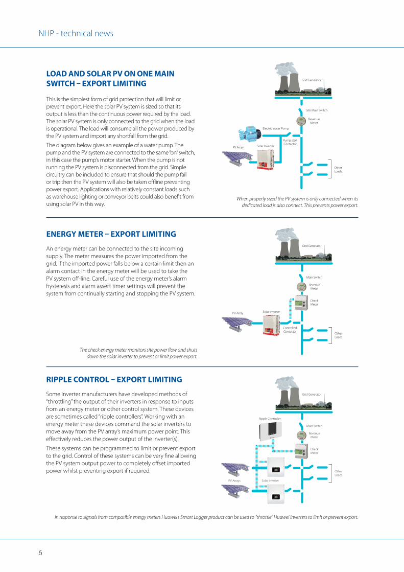
ENERGY METER – EXPORT LIMITING
RIPPLE CONTROL – EXPORT LIMITING
An energy meter can be connected to the site incoming supply. The meter measures the power imported from the grid. If the imported power falls below a certain limit then an alarm contact in the energy meter will be used to take the PV system off-line. Careful use of the energy meter’s alarm hysteresis and alarm assert timer settings will prevent the system from continually starting and stopping the PV system.
Some inverter manufacturers have developed methods of “throttling” the output of their inverters in response to inputs from an energy meter or other control system. These devices are sometimes called “ripple controllers”. Working with an energy meter these devices command the solar inverters to move away from the PV array’s maximum power point. This effectively reduces the power output of the inverter(s).
These systems can be programmed to limit or prevent export to the grid. Control of these systems can be very fine allowing the PV system output power to completely offset imported power whilst preventing export if required.
The check energy meter monitors site power flow and shuts down the solar inverter to prevent or limit power export.
In response to signals from compatible energy meters Huawei’s Smart Logger product can be used to “throttle” Huawei inverters to limit or prevent export.
Energy Meter Control
RevenueMeter
CheckMeter
ControlledContactor
Main Switch
PV Array Solar Inverter
OtherLoads
Grid Generator
Ripple Control
RevenueMeter
CheckMeter
PV Arrays Solar Inverter
Ripple Controller
Main Switch
OtherLoads
Grid Generator
LOAD AND SOLAR PV ON ONE MAIN SWITCH – EXPORT LIMITING
This is the simplest form of grid protection that will limit or prevent export. Here the solar PV system is sized so that its output is less than the continuous power required by the load. The solar PV system is only connected to the grid when the load is operational. The load will consume all the power produced by the PV system and import any shortfall from the grid.
The diagram below gives an example of a water pump. The pump and the PV system are connected to the same “on” switch, in this case the pump’s motor starter. When the pump is not running the PV system is disconnected from the grid. Simple circuitry can be included to ensure that should the pump fail or trip then the PV system will also be taken offline preventing power export. Applications with relatively constant loads such as warehouse lighting or conveyor belts could also benefit from using solar PV in this way.
When properly sized the PV system is only connected when its dedicated load is also connect. This prevents power export.
One main switch
RevenueMeter
Pump startContactor
Site Main Switch
PV Array
Electric Water Pump
Solar Inverter
OtherLoads
Grid Generator

NHP - technical news
7
MAINTAIN PHASE BALANCE - MONITOR NEUTRAL CURRENT
DEDICATED PROTECTION RELAYS
PLC AND ENERGY METER – EXPORT LIMITING AND ANTI-ISLANDING
This requirement is generally easy to meet as most three phase inverters only produce balanced power output. However, in cases where several single phase inverters or micro inverter are used the network operator may require a system to ensure that the PV system output remains balance within a certain limit.
In this case it may be possible to use a single current transformer on the PV system’s neutral to check for output balance. A current sensing relay could be used to take the PV system off-line in the event of too high an imbalance.
Dedicated generator protection relays represent the most accepted methods of grid protection for embedded solar PV generators. These devices range in functionality from providing only the simplest forms of anti-islanding protection through to complete anti-islanding protection with export control, energy meter functionality, remote access and remote control of the PV system.
Typically the protection relay monitors site voltages, currents and power flows and will command the shut down or reduction of the output of the PV system should any operational parameters be exceeded. The protection relay forms only one part of the grid protection system. There are also current transformers (CTs), in the case of an MV or HV connection there will be voltage transformers (VTs), a disconnection device such as a contactor or motor driven circuit breaker and possibly communications hardware to allow remote monitoring and control. The diagram below shows a typical protection relay arrangement.
Using a PLC in combination with an energy meter allows for finer control of power export. Here, as imported power approaches zero, the PLC can command individual inverters to shutdown via a contactor or reduce their output via a ripple controller.
It may be possible to make use of an existing PLC on the site to perform this function. If the PLC programmer has sufficient skill it may also be possible to program the PLC to perform anti-islanding protection. This system has been put into practice on the 100kW installation at NHP’s Laverton, Victoria facility.
PV system output power imbalance is detected by measuring neutral current in the system supply. Once imbalance of sufficient magnitude is detected the systems is taken off-line.
Depending on the model chosen protection relays accept a number of inputs to determine if a PV system should be shut down or have its output limited.
In response to data from the check meter the PLC limits export by either opening inverter contactors or commanding the ripple controller to reduce
power. The PLC can also provide anti-islanding protection.
Phase balance
CurrentTransformer
Current Relay
Multiple AC PV Modules
Contactor
To main Switch Board
L1
N
L2
N
L3
N
Protection Relay
Ripple Controller
Protection Relays
Output to:
inputs from current and voltage sensors
inputs from Network Operator
HMIOutput to:
MFR 1
INFO C OK CTRL
INFO C OK CTRL
RevenueMeter
PLC
CheckMeter
Main Switch
PV Arrays Solar Inverter
OtherLoads
Grid Generator
PLC Control
Ripple Controller

If you would like previous copies of Technical News, simply visit www.nhp.com.au/media and navigate to ‘Catalogues & Literature‘ or download the NHP eCatalogues App by scanning the QR code below. Editorial content: Please address all enquiries to [email protected].
NHP - technical news
AucklandHamiltonNapierNew PlymouthWellington
ChristchurchDunedin
NHP Electrical Engineering Products Pty Ltd A.B.N. 84 004 304 812
NTNL71 11 14© Copyright NHP 2014
AUSTRALIAnhp.com.au
SALES 1300 NHP NHP
NEW ZEALANDnhp-nz.com
SALES 0800 NHP NHP
For more information, scan to download the NHP Catalogues App o�ering exclusive video content, catalogues and literature!
* Rockwell Automation products not available from these locations
MelbourneLavertonAlbury/WodongaDandenong
HobartLauncestonSydney* Newcastle* Wollongong*
CanberraBrisbane*TownsvilleRockhamptonToowoomba*
Cairns AdelaidePerthDarwin
CONCLUSION
REFERENCES
The issues surrounding grid protection will become more important as larger scale embedded solar PV generators become more common. As we have seen here there are many ways to deal with these issues. Unfortunately the requirement for redundant grid protection systems in addition to what are already offered by solar inverters adds to the overall system cost.
Network operators need to be realistic about what constitutes the minimum acceptable level of grid protection for embedded PV generators. Rather than immediately specifying the most complex and expensive product network operators need to consider less costly but still effective alternatives.
Solar PV designers should be prepared to negotiate with the network operators over what is required for grid protection and establish a relationship with the engineer assessing their application. The author has found network engineers to be helpful and interested in technical matters despite being somewhat overworked. The concepts presented in this Technical Newsletter could be used for such a discussion.
1. http://www.sunwiz.com.au/index.php/solar-market-intelligence/solar-hot-spots-target-suburbs.html
2. NHP Technical News #62 Renewable Energy: Part 1 What does it all mean?
3. NHP Technical News #63 Renewable Energy: Part 2 Solar, Wind and the Future for Renewables
4. Applied Protective Relaying 1979 by Westinghouse Electric Corporation, 2nd Printing, “Appendix II, Electrical Power System Device Numbers and Functions”