Reduction of Harmonic Distortions and Subsynchronous ... · International Conference on Power...
6
International Conference on Power Systems Transients – IPST 2003 in New Orleans, USA 1 Reduction of Harmonic Distortions and Subsynchronous Resonances in the Pulsed Power Supply of a Nuclear Fusion Experiment A. M. Miri 1 , C. Sihler 2 (1) University of Karlsruhe, IEH, Kaiserstr. 12, D-76128 Karlsruhe, Germany (e-mail: [email protected]), (2) Max-Planck-Institut für Plasmaphysik (IPP), EURATOM Association, D-85748 Garching, Germany (e-mail: [email protected]) Abstract – The ring-shaped hydrogen plasma of ASDEX Upgrade (AUG), an experimental tokamak for nuclear fu- sion research, carries an electric current up to 1.4 MA. The generation and magnetic confinement of the plasma current requires an electric power of several hundred MVA for short time periods (up to 10 s). To keep away the pulsed load from the public utility grid, the power and energy is pro- vided by separate networks based on flywheel generators. Voltage distortions measured on the 10.5 kV busbars were increased by resonances caused by the subtransient reac- tance of one generator and the stray capacitance of the transmission cables. The shape of the busbar voltages could be significantly improved by a simple modification of exist- ing static var compensators. The dynamic load curves of feedback controlled fusion experiments feature frequencies which are in the same range as the first eigenfrequency of the flywheel generator shaft lines (about 25 Hz). In order to protect the generators from subsynchronous resonances (SSR) torque sensors were installed. The paper presents simulated and measured results and describe the measures taken to achieve a significant reduction of torsional stresses in the generator shaft lines. Keywords – separate network, thyristor converter, harmonic, flywheel generator, shaft line, subsynchronous resonance, SSR I. INTRODUCTION For more than three decades, world-wide efforts have been made to investigate the fusion of the hydrogen iso- topes deuterium and tritium for energy production. A num- ber of principles are available for the experimental devices serving this purpose. One of the most favorable is the toroidal confinement of an ionized gas (plasma) which is heated to about 100 million degrees and confined in a vac- uum chamber by the field of large magnet coils. The type of magnetic plasma confinement device, with a high elec- tric current of the order of several Megaamperes flowing in the plasma, is named tokamak. The performance of a to- kamak discharge can be significantly improved by opti- mising the shape of the plasma column. An elongated D- shaped cross-section is needed for optimal confinement. Position control is required because of the immanent verti- cal instability of elongated plasmas. Shape control is neces- sary to accurately establish and maintain the optimized profile. The Max-Planck-Institut für Plasmaphysik, Garching, commissioned an experimental tokamak, called ASDEX Upgrade (AUG), in 1991. The plasma shape of the AUG tokamak is determined by the poloidal field (PF) magnet coils. Stabilization of the vertical plasma position is per- formed by means of two inner control coils. Six vertical field-coils in a reactor-relevant configuration are the main plasma shaping coils. The ohmic heating coils (OH) induce the plasma current. The currents in these coils are feedback controlled [1]. Multivariable control is considered manda- tory, because of the strong cross-couplings in the system. The power supply of the AUG tokamak consists of three distribution systems (110-85Hz) as shown in Fig. 1, each supplied by a dedicated flywheel generator: EZ2 which solely feeds the toroidal field coils, EZ3 (500 MJ / 144 MVA) and EZ4 (650 MJ / 220 MVA) which feed vertical field coils and additional heating systems. Normally, the power demand of a tokamak experiment can be character- ised by a high active power demand (P > 0) during plasma ramp-up, a relative small demand of P during the plasma flat-top phase and a feedback of active power (P < 0) dur- ing plasma ramp-down, as shown in Fig. 2. Plasma feedback control can cause fast changes of the P demand in the power supply, especially in the EZ3 and EZ4 networks where thyristor converters are supplied al- EZ4 220 MVA / 650 MJ 2,7 kV, 2x3~, 110 - 85 Hz 144 MVA / 500 MJ EZ2 167 MVA / 1,45 GJ 3~ M 3~ J 3~ G 3~ 10 kV, 3~, 50 Hz EZ3 3~ G 3~ M 3~ J 3~ 3~ M/G 3~ 3~ 16 MVA 110 kV, 3~, 50 Hz 10,5 kV, 3~, 110 - 85 Hz J Toroidal magnets Poloidal magnets (ohmic heating, plasma shape + position) Additional heating Fig. 1: Structure of ASDEX Upgrade power supply ...
Transcript of Reduction of Harmonic Distortions and Subsynchronous ... · International Conference on Power...

International Conference on Power Systems Transients – IPST 2003 in New Orleans, USA
1
Reduction of Harmonic Distortions and Subsynchronous Resonancesin the Pulsed Power Supply of a Nuclear Fusion Experiment
A. M. Miri1, C. Sihler2
(1) University of Karlsruhe, IEH, Kaiserstr. 12, D-76128 Karlsruhe, Germany (e-mail: [email protected]),(2) Max-Planck-Institut für Plasmaphysik (IPP), EURATOM Association, D-85748 Garching, Germany (e-mail: [email protected])
Abstract – The ring-shaped hydrogen plasma of ASDEXUpgrade (AUG), an experimental tokamak for nuclear fu-sion research, carries an electric current up to 1.4 MA. Thegeneration and magnetic confinement of the plasma currentrequires an electric power of several hundred MVA forshort time periods (up to 10 s). To keep away the pulsed loadfrom the public utility grid, the power and energy is pro-vided by separate networks based on flywheel generators.Voltage distortions measured on the 10.5 kV busbars wereincreased by resonances caused by the subtransient reac-tance of one generator and the stray capacitance of thetransmission cables. The shape of the busbar voltages couldbe significantly improved by a simple modification of exist-ing static var compensators. The dynamic load curves offeedback controlled fusion experiments feature frequencieswhich are in the same range as the first eigenfrequency ofthe flywheel generator shaft lines (about 25 Hz). In order toprotect the generators from subsynchronous resonances(SSR) torque sensors were installed. The paper presentssimulated and measured results and describe the measurestaken to achieve a significant reduction of torsional stressesin the generator shaft lines.
Keywords – separate network, thyristor converter, harmonic,flywheel generator, shaft line, subsynchronous resonance, SSR
I. INTRODUCTION
For more than three decades, world-wide efforts havebeen made to investigate the fusion of the hydrogen iso-topes deuterium and tritium for energy production. A num-ber of principles are available for the experimental devicesserving this purpose. One of the most favorable is thetoroidal confinement of an ionized gas (plasma) which isheated to about 100 million degrees and confined in a vac-uum chamber by the field of large magnet coils. The typeof magnetic plasma confinement device, with a high elec-tric current of the order of several Megaamperes flowing inthe plasma, is named tokamak. The performance of a to-kamak discharge can be significantly improved by opti-mising the shape of the plasma column. An elongated D-shaped cross-section is needed for optimal confinement.Position control is required because of the immanent verti-cal instability of elongated plasmas. Shape control is neces-sary to accurately establish and maintain the optimizedprofile.
The Max-Planck-Institut für Plasmaphysik, Garching,commissioned an experimental tokamak, called ASDEX
Upgrade (AUG), in 1991. The plasma shape of the AUGtokamak is determined by the poloidal field (PF) magnetcoils. Stabilization of the vertical plasma position is per-formed by means of two inner control coils. Six verticalfield-coils in a reactor-relevant configuration are the mainplasma shaping coils. The ohmic heating coils (OH) inducethe plasma current. The currents in these coils are feedbackcontrolled [1]. Multivariable control is considered manda-tory, because of the strong cross-couplings in the system.
The power supply of the AUG tokamak consists of threedistribution systems (110-85Hz) as shown in Fig. 1, eachsupplied by a dedicated flywheel generator: EZ2 whichsolely feeds the toroidal field coils, EZ3 (500 MJ / 144MVA) and EZ4 (650 MJ / 220 MVA) which feed verticalfield coils and additional heating systems. Normally, thepower demand of a tokamak experiment can be character-ised by a high active power demand (P > 0) during plasmaramp-up, a relative small demand of P during the plasmaflat-top phase and a feedback of active power (P < 0) dur-ing plasma ramp-down, as shown in Fig. 2.
Plasma feedback control can cause fast changes of the Pdemand in the power supply, especially in the EZ3 andEZ4 networks where thyristor converters are supplied al-
EZ4
Additi ona lheati ng
220 MVA / 650 MJ
T oroida lm agnet
2,7 kV, 2x3~,110 - 85 Hz
Poloida lsystem s
Plasm aposition
144 MVA / 500 MJ
EZ2
167 MVA / 1,45 GJ
3~
M3~ J
3~
G3~
10 kV, 3~, 50 Hz
EZ33~
G3~
M3~ J
3~3~
M /G 3~
3~
16 MVA
110 kV, 3~, 50 Hz
10,5 kV, 3~, 110 - 85 Hz
J
Fig. 1: Structure of ASDEX Upgrade power supply
Toroidalmagnets
Poloidal magnets(ohmic heating, plasma
shape + position)
Additionalheating
Fig. 1: Structure of ASDEX Upgrade power supply
...
International Conference on Power Systems Transients – IPST 2003 in New Orleans, USA
2
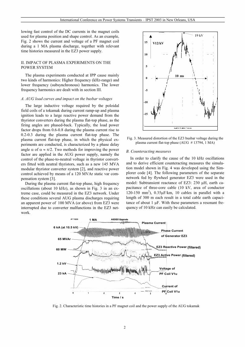
lowing fast control of the DC currents in the magnet coilsused for plasma position and shape control. As an example,Fig. 2 shows the current and voltage of a PF magnet coilduring a 1 MA plasma discharge, together with relevanttime histories measured in the EZ3 power supply.
II. IMPACT OF PLASMA EXPERIMENTS ON THEPOWER SYSTEM
The plasma experiments conducted at IPP cause mainlytwo kinds of harmonics: Higher frequency (kHz-range) andlower frequency (subsynchronous) harmonics. The lowerfrequency harmonics are dealt with in section III.
A. AUG load curves and impact on the busbar voltages
The large inductive voltage required by the poloidalfield coils of a tokamak during current ramp-up and plasmaignition leads to a large reactive power demand from thethyristor converters during the plasma flat-top phase, as thefiring angles are phased-back. Typically, the load powerfactor drops from 0.6-0.8 during the plasma current rise to0.2-0.3 during the plasma current flat-top phase. Theplasma current flat-top phase, in which the physical ex-periments are conducted, is characterized by a phase delayangle � of � � �/2. Two methods for improving the powerfactor are applied in the AUG power supply, namely thecontrol of the phase-to-neutral voltage in thyristor convert-ers fitted with neutral thyristors, such as a new 145 MVAmodular thyristor converter system [2], and reactive powercontrol achieved by means of a 120 MVAr static var com-pensation system [3].
During the plasma current flat-top phase, high frequencyoscillations (about 10 kHz), as shown in Fig. 3 in an ex-treme case, could be measured in the EZ3 network. Underthese conditions several AUG plasma discharges requiringan apparent power of 100 MVA (or above) from EZ3 wereinterrupted due to converter malfunctions in the EZ3 net-work.
Fig. 3. Measured distortion of the EZ3 busbar voltage during theplasma current flat-top phase (AUG # 13794, 1 MA)
B. Counteracting measures
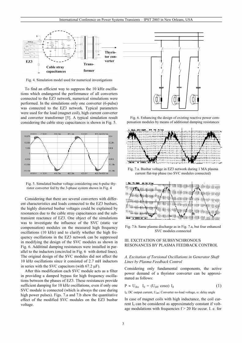
In order to clarify the cause of the 10 kHz oscillationsand to derive efficient counteracting measures the simula-tion model shown in Fig. 4 was developed using the Sim-plorer code [4]. The following parameters of the separatenetwork fed by flywheel generator EZ3 were used in themodel: Subtransient reactance of EZ3: 230 �H, earth ca-pacitance of three-core cable (10 kV, area of conductor120-150 mm2), 0.35�F/km, 10 cables in parallel with alength of 300 m each result in a total cable earth capaci-tance of about 1 �F. With these parameters a resonant fre-quency of 10 kHz can easily be calculated.
Fig. 2. Characteristic time histories in a PF magnet coil and the power supply of the AUG tokamak
Plasma Current
Phase Current
of Generator EZ3
EZ3 Reactive Power
EZ3 Active Power
Voltage of
PF Coil V1u
Current of
PF Coil V1u
1 MA
6 kA (at 10.5 kV)
65 MVAr
60 MW
1.2 kV
23 kA
Time / s
(filtered)
(filtered)
15
10
5
0
-5
-10
-15
19 kV
V12/kV
10 ms
International Conference on Power Systems Transients – IPST 2003 in New Orleans, USA
3
~
3PHAS_Z
l_Lr_L
l_Lr_L
l_Lr_L
~
~
A * sin (2 * pi * f * t + PHI + phi_u)
PHI = 0°
PHI = -120°
PHI = -240°
l_Nr_N
3PHAS_Z1A := 8700
r_L := 15m
l_L := 230ur_N := 100u
phi_u := 0
f := 100
+ A
AM1
+ A
AM2
+ A
AM3
R4
R := 999k
P
.
.
.
TFR3LP1
RFe := 1E18
K2 := 0.25
RCu := 2.5E-2
LH := 0.5
LS := 1.5E-3
K1 := 0.5
.
.
.
TFR3LS1
K0 := 0.08
K2 := 0.02
K3 := 0.06
K1 := 0.04
LS := 5.4E-6
RCu := 9.0E-5
+ AAM7
+ A
AM8
+ A
AM9
+ V
VM1
+ V
VM2
+ V
VM3
P P P
+ V
VM5
+ V
VM6
+ V
VM7
+ V
VM8
P
R6
R := 100k
R7
R := 100k
R8
R := 100k
P PP
+ V
VM4
C1
P
C3
P
C5
P
P
C6
R1
C2
R2
C4
R3
0.8u
0.24u
Thyris-tor con-verter
Trans-
former
EZ3Cable straycapacitances
Fig. 4. Simulation model used for numerical investigations
To find an efficient way to suppress the 10 kHz oscilla-tions which endangered the performance of all convertersconnected to the EZ3 network, numerical simulations wereperformed. In the simulations only one converter (6-pulse)was connected to the EZ3 network. Typical parameterswere used for the load (magnet coil), high current converterand converter transformer [5]. A typical simulation resultconsidering the cable stray capacitances is shown in Fig. 5.
Fig. 5. Simulated busbar voltage considering one 6-pulse thy-ristor converter fed by the 3-phase system shown in Fig. 4
Considering that there are several converters with differ-ent characteristics and loads connected to the EZ3 busbars,the highly distorted busbar voltages could be explained byresonances due to the cable stray capacitances and the sub-transient reactance of EZ3. One object of the simulationswas to investigate the influence of the SVC (static varcompensation) modules on the measured high frequencyoscillations (10 kHz) and to clarify whether the high fre-quency oscillations in the EZ3 network can be suppressedin modifying the design of the SVC modules as shown inFig. 6. Additinal damping resistances were installed in par-allel to the inductors (encircled in Fig. 6 with dotted lines).The original design of the SVC modules did not affect the10 kHz oscillations since it consisted of 2.7 mH inductorsin series with the SVC capacitors (with 67.2 �F).
After this modification each SVC module acts as a filterin providing a damped bypass for high frequency oscilla-tions between the phases of EZ3. These resistances providesufficient damping for 10 kHz oscillations, even if only oneSVC module is connected (which is always the case duringhigh power pulses). Figs. 7.a and 7.b show the quantitativeeffect of the modified SVC modules on the EZ3 busbarvoltage.
Fig. 6. Enhancing the design of existing reactive power com-pensation modules by means of additional damping resistances
Fig. 7.a. Busbar voltage in EZ3 network during 1 MA plasmacurrent flat-top phase (no SVC modules connected)
Fig. 7.b. Same plasma discharge as in Fig. 7.a, but four enhancedSVC modules connected
III. EXCITATION OF SUBSYNCHRONOUSRESONANCES BY PLASMA FEEDBACK CONTROL
A. Excitation of Torsional Oscillations in Generator ShaftLines by Plasma Feedback Control
Considering only fundamental components, the activepower demand of a thyristor converter can be approxi-mated as follows:
P � Udi� Id = (Udi0 cos�) Id (1)Id: DC output current, Udi0: Converter no-load voltage, �: delay angle
In case of magnet coils with high inductance, the coil cur-rent Id can be considered as approximately constant if volt-age modulations with frequencies f > 20 Hz occur. I. e. for

International Conference on Power Systems Transients – IPST 2003 in New Orleans, USA
4
higher frequencies the active power demand of a converterfeeding a large coil is directly proportional to the voltagemodulation Udi�. Considering the nominal values in pulsedduty IdN = 40 kA and Udi0 = 2.76 kV of the AUG ohmicheating (OH) converter, equation (1) yields P(t) � 110 MWcos�(t). Fig. 8 shows an example for these dependencies atthe end of the plasma current flat-top phase of a 800 kAplasma discharge (AUG #15584) . In case of instabilities,e. g., in the plasma current, the plasma current controllercauses a modulation of the ohmic heating (OH) coil currentreference. Because of the large time constant of the OHcoil, this modulation appears in the OH voltage. The corre-sponding active power oscillations with high amplitude acton single machines (EZ3 respectively EZ4). Consideringthat natural frequencies of 23.6 Hz respectively 26 Hz canbe calculated for the shaft lines of the flywheel generatorsEZ3 respectively EZ4, torque measurement systems suitedfor a reliable monitoring of the torsional stress in the shaftlines of both machines were installed [6].
B. Investigation of torsional stress by simulation andmeasurement
Novel torque sensors have been developed for contact-less measurement of mechanical torque by the Universityof Dortmund (Prof. Kulig) and ITWM (Fraunhofer Institutfür Techno- und Wirtschaftsmathematik) [7]. Their mainfields of applications are medium and large diameter shaftlines, especially if no other measurement technique can beused efficiently. The measuring concept is based on theanisotropic magnetostrictive effect in ferromagnetic mate-rials. The sensor signal is directly proportional to the tor-sion of the shaft line.
A dynamic measurement is stringent at dynamic loadcurves as shown in Fig. 2 since generator shaft lines can beexcited to torsional oscillations as described by the fol-lowing n-dimensional differential equation system:
BuKDJ ��� ��� ��� (2)
�(t) Rn: Torsion angle of shaft line; u(t) Rn: Torque;J: Matrix of moments of inertia; D: Damping matrix K:
Stiffness matrix; B: Input matrix for damping torques andelectrical torques
The novel torque sensors were installed close to the cou-pling between the flywheel and the rotor (as indicated byan arrow in Fig. 9). A measurement result typical for the
Fig. 9. Location of the torque sensor (the photo shows the EZ2shaft line which has different parameters but a similar design)
Fig. 8. Impact of plasma current control on EZ4 network (feeding OH converter and others)
Reaction ofgenerator
EZ4
Waveformsin AUG
OH-circuit
Reaction ofgenerator
EZ3
Plasma current in AUG # 15584 (800 kA) 1.0
0.0
IL2: EZ3 stator current{0.1 corresponds 30 kA}
P_EZ3: EZ3 active power{0.1 corresponds 50 MW}
Tors_EZ3: Signal of EZ3torque sensor {0.1 corr. 6 V}
I_EZ4: EZ4 stator current{0.1 corresponds 20 kA}
UOH: OH-coil voltage{0.1 corresponds 3 kV}IOH: OH coil current{0.1 corresponds 20 kA}P_EZ4: EZ4 active power{0.1 corresponds 50 MW}Tors_EZ4: Signal of EZ4torque sensor {0.1 corr. 3 V}
� �
International Conference on Power Systems Transients – IPST 2003 in New Orleans, USA
5
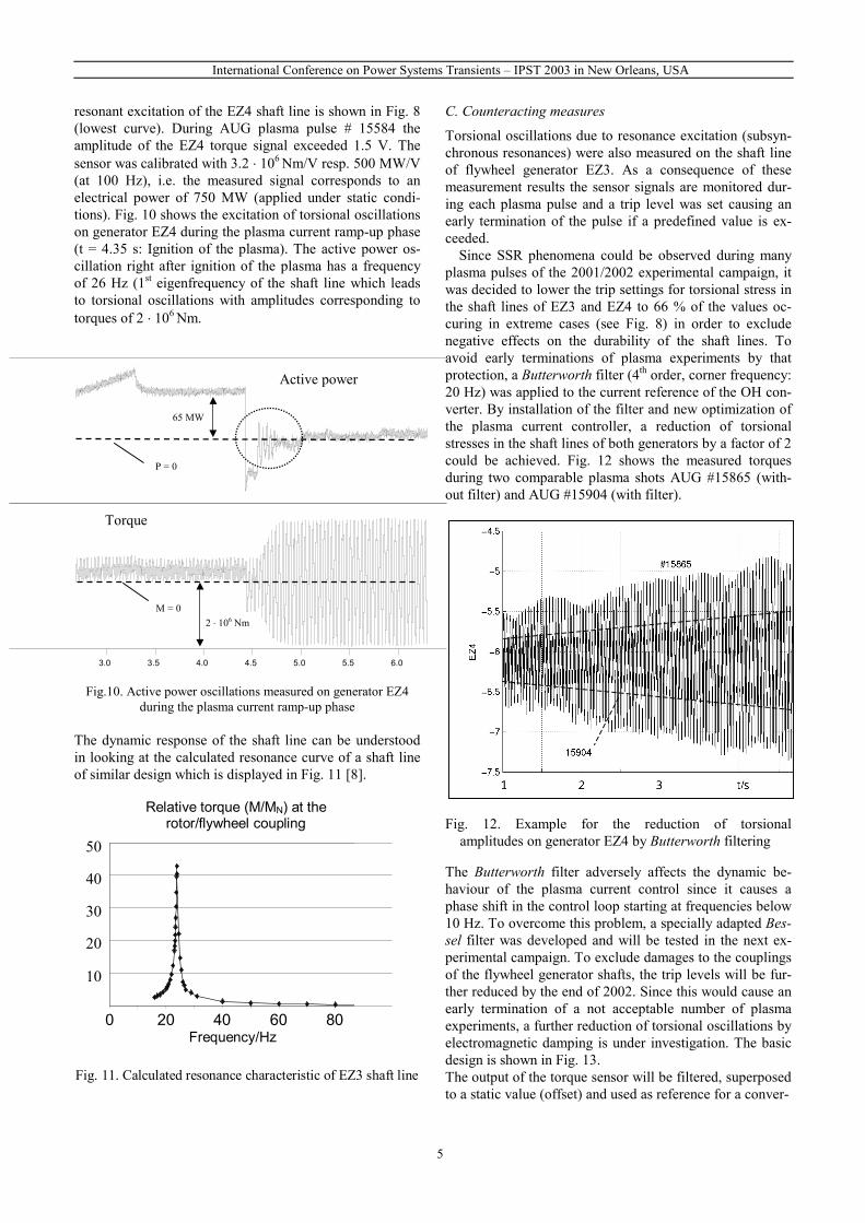
resonant excitation of the EZ4 shaft line is shown in Fig. 8(lowest curve). During AUG plasma pulse # 15584 theamplitude of the EZ4 torque signal exceeded 1.5 V. Thesensor was calibrated with 3.2 � 106 Nm/V resp. 500 MW/V(at 100 Hz), i.e. the measured signal corresponds to anelectrical power of 750 MW (applied under static condi-tions). Fig. 10 shows the excitation of torsional oscillationson generator EZ4 during the plasma current ramp-up phase(t = 4.35 s: Ignition of the plasma). The active power os-cillation right after ignition of the plasma has a frequencyof 26 Hz (1st eigenfrequency of the shaft line which leadsto torsional oscillations with amplitudes corresponding totorques of 2 � 106 Nm.
Fig.10. Active power oscillations measured on generator EZ4during the plasma current ramp-up phase
The dynamic response of the shaft line can be understoodin looking at the calculated resonance curve of a shaft lineof similar design which is displayed in Fig. 11 [8].
C. Counteracting measures
Torsional oscillations due to resonance excitation (subsyn-chronous resonances) were also measured on the shaft lineof flywheel generator EZ3. As a consequence of thesemeasurement results the sensor signals are monitored dur-ing each plasma pulse and a trip level was set causing anearly termination of the pulse if a predefined value is ex-ceeded.
Since SSR phenomena could be observed during manyplasma pulses of the 2001/2002 experimental campaign, itwas decided to lower the trip settings for torsional stress inthe shaft lines of EZ3 and EZ4 to 66 % of the values oc-curing in extreme cases (see Fig. 8) in order to excludenegative effects on the durability of the shaft lines. Toavoid early terminations of plasma experiments by thatprotection, a Butterworth filter (4th order, corner frequency:20 Hz) was applied to the current reference of the OH con-verter. By installation of the filter and new optimization ofthe plasma current controller, a reduction of torsionalstresses in the shaft lines of both generators by a factor of 2could be achieved. Fig. 12 shows the measured torquesduring two comparable plasma shots AUG #15865 (with-out filter) and AUG #15904 (with filter).
Fig. 12. Example for the reduction of torsional amplitudes on generator EZ4 by Butterworth filtering
The Butterworth filter adversely affects the dynamic be-haviour of the plasma current control since it causes aphase shift in the control loop starting at frequencies below10 Hz. To overcome this problem, a specially adapted Bes-sel filter was developed and will be tested in the next ex-perimental campaign. To exclude damages to the couplingsof the flywheel generator shafts, the trip levels will be fur-ther reduced by the end of 2002. Since this would cause anearly termination of a not acceptable number of plasmaexperiments, a further reduction of torsional oscillations byelectromagnetic damping is under investigation. The basicdesign is shown in Fig. 13.The output of the torque sensor will be filtered, superposedto a static value (offset) and used as reference for a conver-
3.0 3.5 4.0 4.5 5.0 5.5 6.0
65 MW
P = 0
M = 02 � 106 Nm
Active power
Torque
Relatives Torsionsmoment Mkuppl/Mnan der Kupplung SchwungrGenerator, Element-Nr. 37, Log. Dekr.=0.034
0,0
10,0
20,0
30,0
40,0
50,0
0 10 20 30 40 50 60 70 80
Frequenz in Hz
Relative torque (M/MN) at therotor/flywheel coupling
0 20 40 60 80Frequency/Hz
50
40
30
20
10
Fig. 11. Calculated resonance characteristic of EZ3 shaft line
cms
1 2 3 t/s
cms

International Conference on Power Systems Transients – IPST 2003 in New Orleans, USA
6
ter feeding a test coil (magnet separate from AUG experi-ment). If subsynchronous resonances occur, the measuredoscillation will be phae shifted and used as input of the‘damping converter’. The damping converter will producean oscillating load curve with a phase shift of about 180°compared to the velocity of the torsional oscillation. Sinceit will be operated at the measured eigenfrequency of theshaft, only little power is necessary to damp these oscilla-tions (see Fig. 11). The power of the ‘damping converter’will be limited to low values, for safety reasons. Protectionsystems will ensure a safe operation of the damping con-verter. First tests will start in January 2003.
IV. CONCLUSIONS
During plasma experiments performed with experimentaltokamaks a high degree of harmonic distortions can occurin the separate networks of the pulsed power supply. Dis-tortions measured on the 10.5 kV busbars of the ASDEXUpgrade power supply were increased by resonances. In-vestigations performed by simulation and measurementshow that the power quality in the pulsed network could besignificantly improved by a simple modification of existingstatic var compensators (SVC).Plasma feedback control can cause subsynchronous reso-nances in the shaft lines of the flywheel generators feedingthe experiments. Therefore, devices capable to measure the
torsional stress in the shaft line are stringent for generatorprotection. The mechanical stresses in the shafts could bereduced by a factor of 2 in applying a Butterworth filter tothe plasma current control loop. Further progress shall beachieved by means of a separate thyristor converter pro-viding electromagnetic damping in case of SSR excitation.
REFERENCES
[1] W. Treutterer et al., Plasma Shape Control Design in ASDEXUpgrade, Proceedings of 19th Symposium on Fusion Technol-ogy, Lisbon, Portugal (1996), pp. 933-936
[2] C.-P. Käsemann et al., 145 MVA Modular Thyristor ConverterSystem with Neutral Control for ASDEX Upgrade, Proc. 22nd
SOFT, Fusion Engineering and Design, Elevier Science, 2003.[3] C. Sihler, M. Huart, B. Streibl, D. Hrabal, H. Schmitt, Tran-
sient Performance of Vacuum-Switched Static VAR Compen-sators Optimised for Large Induct. Loads, Proc. IPST 2001,Brazil, pp. 481-486
[4] SIMEC, Simplorer, Version 4.2, Chemnitz, Germany, 2000[5] A. M. Miri, “Ausgleichsvorgänge in Elektroenergiesyste-
men”, Springer Verlag, ISBN 3-540-67735-6, 2000[6] C. Sihler et al., Excitation of Torsional Oscillations in Gen-
erator Shaft Lines by Plasma Feedback Control, Proc. 22nd
SOFT, Fusion Engineering and Design, Elevier Science, 2003.[7] P. Lang, T. S. Kulig, http://www.itwm.fhg.de/as/projects/tor-
sion/torsion_dt.html, 1999[8] T. S. Kulig et al., Torsionsbeanspruchungen im Wellenstrang
des Stoβkurzschluβgenerators EZ3 bei Plasmaexperimenten,IPP Internal Report, unpublished, Juli 2002
GSG
3~J
EZ4
10.5 kV, 3~, 85 - 110 Hz
ASDEX Upgrade thyristor converter loads(dynamic loads)
�cos0 DCdidamp IUP
constant
IDC_ref (feedforward) +
Torque sensor
Gate controlset
Signal conditioning,modification and
control
iAC
_ref (feedback)
Pdamp
Dampingconverter
Id
t10 s
TS6
10 kA
Fig. 13. Basic design of feedback loop for electromagnetic damping of subsynchronous resonances
cms
=


![1 Semi-SupervisedLearningwithConditional Harmonic Mixing€¦ · Conditional reduction (Burges [2005]). In this paper, we propose a new graph-based approach Harmonic Mixing to semi-supervised](https://static.fdocuments.us/doc/165x107/6025ad3779113b70db7e000e/1-semi-supervisedlearningwithconditional-harmonic-mixing-conditional-reduction-burges.jpg)