reducing the structural mass of a real-world double girder overhead
13
International Journal of Advances in Engineering & Technology, Apr., 2015. ©IJAET ISSN: 22311963 150 Vol. 8, Issue 2, pp. 150-162 REDUCING THE STRUCTURAL MASS OF A REAL-WORLD DOUBLE GIRDER OVERHEAD CRANE V.V. Arun Sankar 1 , Deepak Vijayan.P 2 , Ibrahim Ashraf. MY 2 1 Assistant Professor, 2 UG Student, Karpagam College of Engineering, Coimbatore, India ABSTRACT Overhead cranes are often subjected to heavy stresses on its structure as they carry heavy loads. Stress on its structure leads to unwanted vibrations that lead to structural damages and thereby reduced life span. In companies where the use of crane is of prime importance stresses acting on it plays a major role in its structural behaviour. One way of reducing its stresses and there by its life span is by optimization and mass reduction. The main aim here is to reduce the structural mass of a real-world double girder overhead crane, through the use of modern computer modelling and simulation methods and applications. The structural mass reduction are designed and verified by structural static stress simulations. KEYWORDS: overhead crane, stresses on Double Girder Overhead Crane, structural optimization in a Double Girder Overhead Crane, Stress Analysis of Crane Hook I. INTRODUCTION There are various types of overhead cranes with many being highly specialized, but the great majority of installations fall into one of three categories: a) Top running single girder bridge cranes b) Top running double girder bridge cranes c) Under-running single girder bridge cranes For high capacities, over 30 tons, usually Electric Overhead Cranes (EOT) are the preferred type. In this work we prefer a Top running double girder bridge crane. Figure. 1 Double girder electric overhead crane The basic components in an EOT crane are: 1) Bridge 2) End trucks 3) Bridge Girder(s) 4) Runway 5) Runway Rail 6) Hoist 7) Trolley 8) Bumper (Buffer).
Transcript of reducing the structural mass of a real-world double girder overhead
International Journal of Advances in Engineering & Technology, Apr., 2015.
©IJAET ISSN: 22311963
150 Vol. 8, Issue 2, pp. 150-162
REDUCING THE STRUCTURAL MASS OF A REAL-WORLD
DOUBLE GIRDER OVERHEAD CRANE
V.V. Arun Sankar1, Deepak Vijayan.P2, Ibrahim Ashraf. MY2 1Assistant Professor, 2UG Student,
Karpagam College of Engineering, Coimbatore, India
ABSTRACT Overhead cranes are often subjected to heavy stresses on its structure as they carry heavy loads. Stress on its
structure leads to unwanted vibrations that lead to structural damages and thereby reduced life span. In
companies where the use of crane is of prime importance stresses acting on it plays a major role in its structural
behaviour. One way of reducing its stresses and there by its life span is by optimization and mass reduction. The
main aim here is to reduce the structural mass of a real-world double girder overhead crane, through the use of
modern computer modelling and simulation methods and applications. The structural mass reduction are
designed and verified by structural static stress simulations.
KEYWORDS: overhead crane, stresses on Double Girder Overhead Crane, structural optimization in a
Double Girder Overhead Crane, Stress Analysis of Crane Hook
I. INTRODUCTION
There are various types of overhead cranes with many being highly specialized, but the great majority
of installations fall into one of three categories:
a) Top running single girder bridge cranes
b) Top running double girder bridge cranes
c) Under-running single girder bridge cranes
For high capacities, over 30 tons, usually Electric Overhead Cranes (EOT) are the preferred type. In
this work we prefer a Top running double girder bridge crane.
Figure. 1 Double girder electric overhead crane
The basic components in an EOT crane are: 1) Bridge 2) End trucks 3) Bridge Girder(s) 4) Runway 5)
Runway Rail 6) Hoist 7) Trolley 8) Bumper (Buffer).
International Journal of Advances in Engineering & Technology, Apr., 2015.
©IJAET ISSN: 22311963
151 Vol. 8, Issue 2, pp. 150-162
II. GUIDELINES FOR SELECTING AN EOT CRANE
To select the correct crane envelope that will fit in the building foot print, the user must identify and
pass on some key information to the supplier. The following are the various considerations for
selection of an EOT crane a) Crane capacity, b) Required lifting height, c) Runway height, d)
Clearance, e) Building Width f) Clear Span, g) Building Height, h) Runway Size & Length, i) Hook
Approach & End Approach.
III. STRUCTURAL DESIGN CONSIDERATIONS
A crane structure is subjected to following types of loads (forces):
a) Dead Loads – A load that is applied steadily and remains in a fixed position relative to the
structure. The dead load is a steady state and does not contribute to the stress range.
b) Live Load - A load which fluctuates, with slow or fast changes in magnitude relative to the
structure under consideration.
c) Shock Load – A load that is applied suddenly or a load due to impact in some form. All these
loads induce various types of stresses that can be generally classified in one of four categories:
• Residual stresses
• Structural stresses
• Thermal stresses
• Fatigue stresses
Of all these stresses, the fatigue stresses demand the maximum attention. Crane runway girders are
subjected to repetitive stressing and un-stressing due to number of crane passages per hour (or per
day).Since it, is not easy to estimate the number of crane passages, for design purposes it is assumed
that the number of stress fluctuations corresponds to the class of the crane a specified in the codes.
When designing structures supporting crane, the main loads and forces to be considered are:
a) Vertical loads – The predominant loading on the crane supporting structure is vertical loads and
is usually supplied by manufactures by way of maximum wheel loads.
These loads may differ from wheel to wheel depending on the relative positions of the crane
components and the lifted load:
b) Side thrust lateral loads - Crane side thrust is a horizontal force of short duration applied
transversely by the crane wheels to the rails. Side thrust arises from one or more of:
Acceleration and deceleration of the crane bridge and the crab
Impact loads due to end stops placed on the crane runway girder
Off-vertical lifting at the start of hoisting.
Tendency of the crane to travel obliquely.
Skewing or crabbing of the crane caused by the bridge girders not running perpendicular to the
runways. Some normal skewing occurs in all bridges.
Misaligned crane rails or bridge end trucks.
The forces on the rail are acting in opposite directions on each wheel of the end carriage and
depend on the ratio of crane span to wheel base.
c) Traction Load - Longitudinal crane traction force is of short duration, caused by crane bridge
acceleration or braking.
d) Bumper Impact - This is longitudinal force exerted on the crane runway by a moving crane
bridge striking the end stop.
IV. BRIDGE CRANE STRUCTURAL CALCULATIONS
A solid walled construction has been taken into consideration where the bridge is welded to the end
trucks. The major calculation pertain to double girder overhead crane 50/12,5, produced by NEW
TECHNO INDUSTRIES–CHENNAI. The crane has normal duty cycle main load capacity 50 tons
and auxiliary load capacity 12,5 tons. Some of the major crane parameters are listed in Table 1.
International Journal of Advances in Engineering & Technology, Apr., 2015.
©IJAET ISSN: 22311963
152 Vol. 8, Issue 2, pp. 150-162
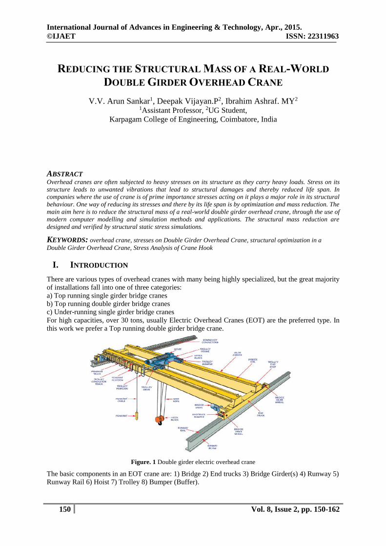
Table 1 Parameters of crane, type 50/12, 5
Figure. 2 Metal structure with major dimensions
Bridge span is given L = 28500 mm; crab base is given M = 2850mm;
Crane base B is predefined by the relation.
B = 4600mm.
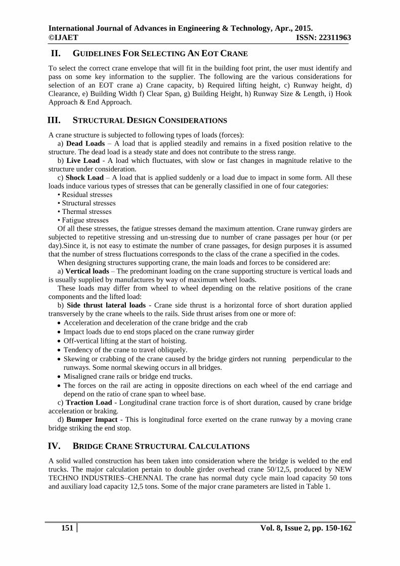
All other dimensions are determined by recommendatory relations.
Figure. 3 Main girder partial view and cross section
International Journal of Advances in Engineering & Technology, Apr., 2015.
©IJAET ISSN: 22311963
153 Vol. 8, Issue 2, pp. 150-162
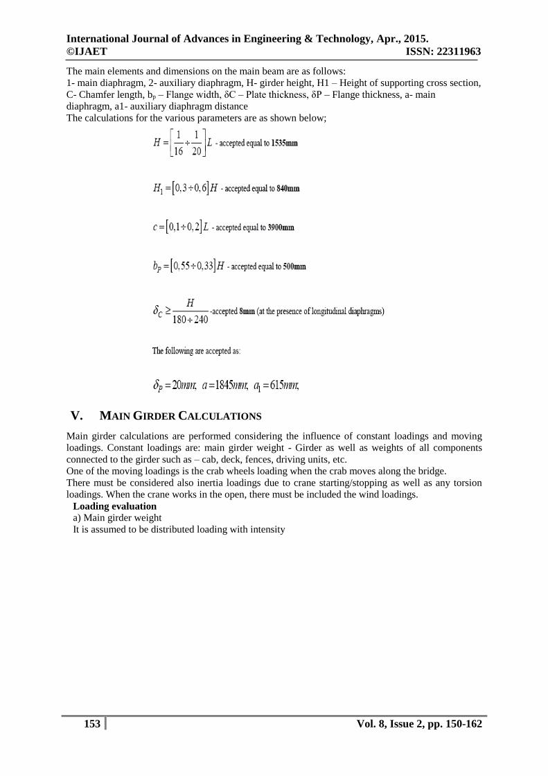
The main elements and dimensions on the main beam are as follows:
1- main diaphragm, 2- auxiliary diaphragm, H- girder height, H1 – Height of supporting cross section,
C- Chamfer length, bp – Flange width, δC – Plate thickness, δP – Flange thickness, a- main
diaphragm, a1- auxiliary diaphragm distance
The calculations for the various parameters are as shown below;
V. MAIN GIRDER CALCULATIONS
Main girder calculations are performed considering the influence of constant loadings and moving
loadings. Constant loadings are: main girder weight - Girder as well as weights of all components
connected to the girder such as – cab, deck, fences, driving units, etc.
One of the moving loadings is the crab wheels loading when the crab moves along the bridge.
There must be considered also inertia loadings due to crane starting/stopping as well as any torsion
loadings. When the crane works in the open, there must be included the wind loadings.
Loading evaluation
a) Main girder weight
It is assumed to be distributed loading with intensity
International Journal of Advances in Engineering & Technology, Apr., 2015.
©IJAET ISSN: 22311963
154 Vol. 8, Issue 2, pp. 150-162
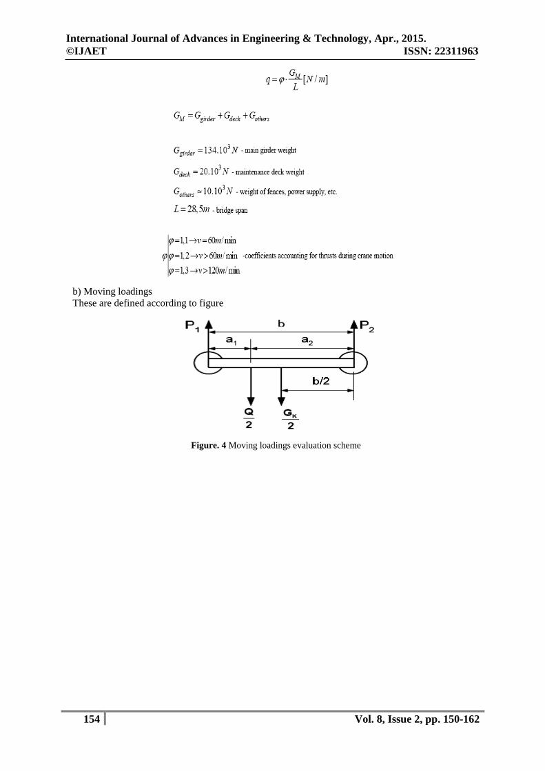
b) Moving loadings
These are defined according to figure
Figure. 4 Moving loadings evaluation scheme

International Journal of Advances in Engineering & Technology, Apr., 2015.
©IJAET ISSN: 22311963
155 Vol. 8, Issue 2, pp. 150-162
Figure. 5 Main girder calculation scheme due to moving loadings a – unequal loadings; b – equal loadings
Calculations are proceeded as shown in figure 5. Now the difference, here is that loadings are applied
in the vertical and horizontal planes.

International Journal of Advances in Engineering & Technology, Apr., 2015.
©IJAET ISSN: 22311963
156 Vol. 8, Issue 2, pp. 150-162
Figure6. Stresses acting on Main Girder
International Journal of Advances in Engineering & Technology, Apr., 2015.
©IJAET ISSN: 22311963
157 Vol. 8, Issue 2, pp. 150-162
VI. DESIGN AND ANALYSIS OF MAIN GIRDER
The design and analysis for the main girders has been carried out and a comparative study has been
done.
There are two identical main girders. Each one is 28100mm long and consists of:
top flange and bottom flange (thickness 20mm, width 500mm).
side plates (thickness 8mm).
main and aux diaphragms (thickness 6mm).
rail (type KP70) fixed by sleepers to the main girder’s top flange - 52 -
The mass of a single main girder is 11523kg. The major components of the girder are listed in
Table 2 and the cross-section parameters of the girder are shown in Fig. 7.
Table 2 Major Components in a girder
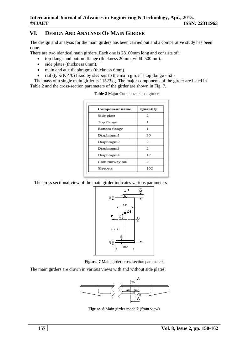
The cross sectional view of the main girder indicates various parameters
Figure. 7 Main girder cross-section parameters
The main girders are drawn in various views with and without side plates.
Figure. 8 Main girder model2 (front view)
International Journal of Advances in Engineering & Technology, Apr., 2015.
©IJAET ISSN: 22311963
158 Vol. 8, Issue 2, pp. 150-162
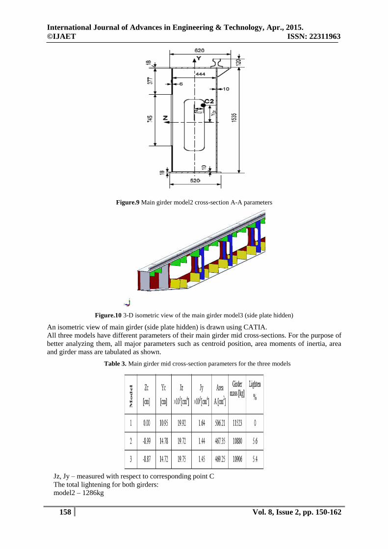
Figure.9 Main girder model2 cross-section A-A parameters
Figure.10 3-D isometric view of the main girder model3 (side plate hidden)
An isometric view of main girder (side plate hidden) is drawn using CATIA.
All three models have different parameters of their main girder mid cross-sections. For the purpose of
better analyzing them, all major parameters such as centroid position, area moments of inertia, area
and girder mass are tabulated as shown.
Table 3. Main girder mid cross-section parameters for the three models
Jz, Jy – measured with respect to corresponding point C
The total lightening for both girders:
model2 – 1286kg

International Journal of Advances in Engineering & Technology, Apr., 2015.
©IJAET ISSN: 22311963
159 Vol. 8, Issue 2, pp. 150-162
model3 – 1234kg
It is evident that model 1 has the heavies girder – 11523kg. The introduction of the new main girder
design, through model 2 and 3 lightens the girder with an average of 5.5%. It means that the crane
mass could decreased with 1200 to 1300kg, by just making these main girder redesign procedures.
Table 3 also shows that the new designs follow closely the parameters of the basic crane model. The
area moments of inertia, critical for the stressed behaviour, do not deviate significantly, which is an
indication that the new models should have stressed behaviour similar to the basic crane. It is
compulsory to check for this stress response by using the FE method.
Figure. 11 3-D basic model final mesh (some main girder and end truck plates are hidden)
The mesh consists of 38962 finite elements and 72937 nodes. The major element types used are:
10-Node Quadratic Tetrahedron Solid187- 10-Node Tetrahedral Structural Solid
20-Node Quadratic Hexahedron Solid186 - 20-Node Hexahedral Structural Solid
20-Node Quadratic Wedge Solid186 - 20-Node Hexahedral Structural Solid
Quadratic Quadrilateral Contact Conta174 - Hi-order Surface to Surface Contact
Quadratic Quadrilateral Target Targe170 - Surface Contact Target;
Quadratic Triangular Contact Conta174 - Hi-order Surface to Surface Contact
Table 4. Properties of Steel bridge structure

International Journal of Advances in Engineering & Technology, Apr., 2015.
©IJAET ISSN: 22311963
160 Vol. 8, Issue 2, pp. 150-162
Fig.12 Equivalent (von-Mises) stresses in the bridge structure (crab and side plate of the far girder are hidden;
stress values are measured at certain points)
Figure. 13 Vertical (Y-axis) deformation of the crane (Deformation values are measured at certain points)
The model allows us to measure at points and cross-sections that are inaccessible to the real gauging
experiments, Figure. 14
Figure. 14 Equivalent stresses measured at points on the diaphragms, inner walls of side plates and main girder
mid cross-section

International Journal of Advances in Engineering & Technology, Apr., 2015.
©IJAET ISSN: 22311963
161 Vol. 8, Issue 2, pp. 150-162
VII. CONCLUSION
From the results obtained using analytical and from the software oriented results suggest that the two
models – model2 and model3 of lighter crane structure have been designed in which the modified side
plate has the same thickness but two types of holes are cut – simple holes and rimmed holes. These
new designs succeed in reducing the model1 crane mass respectively by 5.6% and 5.4%. The new
models, however, are set to various checks in order to prove their conformity to theoretical
considerations and prove that their static response is similar to that of the original crane. The varieties
of checks go primarily through stress analyses, horizontal and vertical deflection analyses of the
bridge. The new design models – model2 and model3, are set to various checks in order to prove their
conformity to theoretical considerations and prove that their static response is similar to that of the
original crane. The varieties of checks go primarily through stress analyses, horizontal and vertical
deflection analyses of the bridge. The models proved to conform to theory and their static structural
response preserves the response of the original crane structure.
Figure 15. Model2 is one of the options to reduce the bridge mass
REFERENCES
[1] Abhinay Suratkar, et al Design Optimization of Overhead EOT Crane Box Girder Using Finite Element
Analysis, IJERT Vol.2 - Issue 7 (July - 2013)
[2] Vishal Shukla et al, Design Optimization of overhead EOT crane box girder using Finite Element Method,
IJERT (7):720
[3] Abhinay Suratkar, Vishal Shukla, 3-D Modelling And Finite Element Analysis Of EOT Crane, International
Journal of Mechanical and Production Engineering, ISSN: 2320-2092, Volume- 1, Issue- 2, Aug-2013
[4] Apeksha.K.Patel, Prof. V.K.Jani, Design and Dynamic Analysis of70t Double Girder Electrical Overhead
Crane, Journal of Information, Knowledge and Research in Mechanical Engineering
[5] Naresh Chauhan, P.M. Bhatt, Improving the Durability of the E.O.T. Crane Structure by Finite Element
Analysis, and Optimize the Hook Material for Improving its Solidity, International Conference On Modelling
Optimization And Computing, Volume 38, 2012, Pages 837–842
[6] Rajpandian R, Design and Analysis of Overhead Crane Structural Columns, IOSR Journal of Electronics and
Communication Engineering, PP 69-75
[7] Ashish Gohil, Bridge Girder Design of an EOT Crane Structure—A CAD Approach, International
Conference at Nirma University, NUCONE 2007
[8] Petkov G. et al., Experimental studies of materials handling machines, Sofia, 1980
[9] Kolarov I., N. Kotzev, S. Stoychev, Metal structures of materials handling and building machines, Sofia,
1990.
[10] Yanakiev A., M. Georgiev, Modelling of materials handling machines and systems, Sofia, 1996
[11] Cook R., Finite Element Modelling for Stress Analysis, John Wiley & Sons, 1995
[12] Sumtzov A. A. et al., Results of bridge cranes gauging experiments, 1970
[13] CMAA Specification No. 70 (Top Running Bridge and Gantry Type Multiple Girder Electric Overhead
Traveling Cranes)
[14] ASME B30.17 - 2003 Overhead and Gantry Cranes (Top Running Bridge, Single Girder, Underhung Hoist)
[15] FEM 9.901 Rules for the Design of Series Lifting Equipment and Cranes Equipped with Series Lifting
Equipment
[16] Ivanchenko, F., Designing and calculating materials handling machines, Kiev, 1983

International Journal of Advances in Engineering & Technology, Apr., 2015.
©IJAET ISSN: 22311963
162 Vol. 8, Issue 2, pp. 150-162
[17] Slavchev Y., Research on Carrying Metal Structure of Overhead Bridge Cranes, Lambert Academic
Publishing, ISBN 978-3-8433-5644-2, 2010, Saarbrücken, Deutschland
AUTHORS
V.V. Arun Sankar is working as an Assistant Professor in Karpagam College of
Engineering, Coimbatore, India. He has completed Masters in Engineering (M.E.) in the
year 2011. From 2011 he has been working in the same College.
P. Deepak Vijayan is studying his III yr Bachelors in Engineering (B.E.) in Mechanical
Engg. in Karpagam College of Engineering, Coimbatore, India.
M.Y. Ibrahim Ashraf is studying his III yr Bachelors in Engineering (B.E.) in
Mechanical Engg. in Karpagam College of Engineering, Coimbatore, India