Reducing Dilution With Narrow-vein Mining€¦ · • Cemented rockfill and waste rock considered...
38
April 2020 WEBINAR: Reducing dilution in mechanized narrow vein mining Paul Salmenmaki, P.Eng.
Transcript of Reducing Dilution With Narrow-vein Mining€¦ · • Cemented rockfill and waste rock considered...

April 2020
WEBINAR:Reducing dilution in
mechanized narrow vein mining
Paul Salmenmaki, P.Eng.

Introduction
2
AMC has conducted numerous studies for operating mines to reduce dilution for mechanized narrow vein mining methods.
This webinar presents a high-level discussion of a study conducted by AMC to determine the optimum (minimum) dilution that could be reasonably applied to a narrow vein orebody through the use of:
• Compact equipment• Varying development sizes
• Drill and blast designs

Introduction
3
The mining methods include:
• Longhole open stoping (LHOS)• Mechanized cut and fill (CAF)
Notes: Resuing is not considered. Handheld equipment not included.
What is mining dilution?
4
Dilution can be classified as planned or unplanned.
Planned dilution: Waste material incorporated into the stope when designing practical mining shapes. Depends on the vein geometry, thickness, orebody dip, and local ground conditions.
Unplanned dilution: Consists of waste mined due to overbreak, which may result from poor drilling, blasting or as any waste incorporated during mucking.

What is ore loss?
5
Ore loss can similarly be classified as planned and unplanned dilution.
Planned ore loss represents the ore-grade material that has been excluded from the mining block at the stope design stage, whereas unplanned ore loss is the part of the mining block that remains in the stopes after mining.

Vein characterization
6
The broad aim was to identify the general variability in vein width, geometry, and lateral extent (strike and dip) and to identify geotechnical conditions that may determine the applicability of the mining methods.
The findings included:• Consistent vein strike 1,500 m.• Vein width ranging from 0.5 m to more than 5 m.• Ground condition ranging from poor to good, across strike and depth extents.• Cemented rockfill and waste rock considered to aid ground support.• LHOS and CAF used at the mine, with potential to optimize sublevel spacing
and mining sequence.

Optimized dilution scenarios
7
Using the results of the vein characterization study, it was concluded that the minimization of dilution for LHOS and CAF would be based on:
• Vein widths of 1.5 m, 2.25 m, 3.5 m, and 5 m.• Varied ore drive dimensions, and profiles (rectangular and shanty-back).• Orebody dips of 61°, 66°, 68°, and 72°.
Note:
Not every possible scenario is considered in the case study. It is a subset specific to the client's requirements.
Productivity versus dilution trade-off was not assessed as part of the case study.
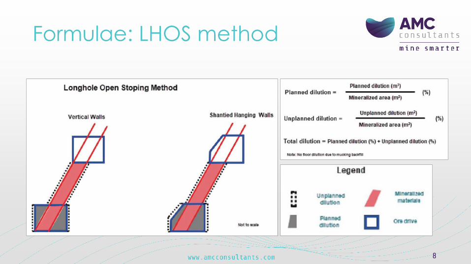
Formulae: LHOS method
8

Formulae: CAF method
9

Benchmarking and case studies
10
AMC used benchmarking and case studies to:• Identify dilution experienced at different narrow vein mines.• Guide equipment selection, and drill-and-blast designs.• Technical services procedures and recommendations.
The optimum dilution is determined by balancing the cost of mining and processing dilution against the cost of losing ore. Given the value of the ore for this case study, recovery was given priority over dilution, with a target recovery of 100%.
However, in mines with lower grade ore, the focus may be more on dilution than recovery.

Equipment – existing fleetExamined the existing fleet of stope equipment at the mine:• Jumbos• LHDs• Longhole drills• Bolters
Established optimal drill-and-blast designs for the:• Selected vein widths, dips, and drift profiles (square and shanty)• Drift size (height and width)• Mining methods (CAF and LHOS)
11
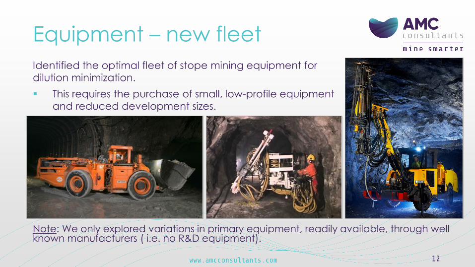
Equipment – new fleetIdentified the optimal fleet of stope mining equipment for dilution minimization. This requires the purchase of small, low-profile equipment
and reduced development sizes.
12
Note: We only explored variations in primary equipment, readily available, through well known manufacturers ( i.e. no R&D equipment).

CAF dilution resultsIn general, minimum dilution is achieved using the lowest practical drift heights and good ground for CAF.
For CAF mining, the practical idealized dilution targets are all achieved with the regular veins and the results are as follows:
Note: Generally narrower veins (1.5 and 2.25) fit inside the width of the drift and total dilution is nearly the same between dips. However, the wider veins (3.5 and 5 m) have lower total dilution when vein dips are steeper.
13
Vein Total Drive Drive Dip Drive Width Dilution Width Heigth Degress Profile
(m) (%) (m) (m)1.5 66 2.7 3.0 61.0 Shanty
2.25 31 2.7 3.0 61.0 Shanty3.5 19 4.2 4.0 66.0 Shanty5 14 5.8 5.0 72.0 Shanty
CAF example design
14
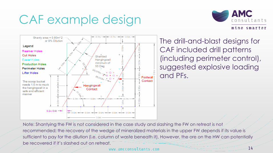
The drill-and-blast designs for CAF included drill patterns (including perimeter control), suggested explosive loading and PFs.
Note: Shantying the FW is not considered in the case study and slashing the FW on retreat is not recommended; the recovery of the wedge of mineralized materials in the upper FW depends if its value is sufficient to pay for the dilution (i.e. column of waste beneath it). However, the ore on the HW can potentially be recovered if it’s slashed out on retreat.

CAF example dilution
15

LHOS dilution resultsIn general, minimum dilution is achieved using the optimal equipment, smaller ore drives and good ground for the LHOS methods.
For LHOS mining, the practical idealized dilution targets are:
Note: LHOS reported at 660 for representative results of orebody. Steeper dip inclinations generally have lower total dilution.
The veins with minimum dilution were regular. Irregular veins experienced higher dilution. 16
Vein Total Drive Drive Dip Level Height Drive Width Dilution Width Heigth (Degrees) floor to floor Profile
(m) (%) (m) (m) (m)1.5 20 2.7 3.0 66.0 20 Shanty
2.25 15 3.0 3.0 66.0 20 Shanty3.5 10 4.0 4.0 66.0 20 Shanty5 9 5.0 5.0 66.0 20 Shanty

Example LHOS design for an irregular vein
AMC used the ideal stope and drive dilution results for the basis to create drill and- blast designs, which included slot raise, production rings, and powder factors (PFs) for LHOS.
17

Example LHOS design for a regular vein
18

Key aspect to achieve targetsKey aspects in attempting to achieve these targets will be:• Shanty-back ore drives, when practicable and appropriately
supported.• For narrower veins (< 3.0 m wide), minimizing the ore drive size
(width and height) • For wider veins (> 3.0 m wide), designing / excavating ore drives
that approach the vein width • Following AMC recommended best practices in design, drilling,
blasting, and quality control.Note: The veins with minimum dilution were regular. Irregular veins experienced higher dilution.
19

Reducing dilutionTo target idealized dilution, AMC recommends closely monitoring three areas:
20
Drive dimension optimization
Drill-and-blast
practices
Overall quality control

Drive dimension optimization -CAF and ore drives for LHOS
21
• Purchase equipment that fits into 2.7 m x 3 m drift.
• Consider the use of shanty ore drive backs (min 550 dip, can be supported, can fit LHD bucket, can fit oval vent on back).
• Minimize development into orebody hanging wall (HW) cubbies, electric bay, remucks, etc.
• Reduce drillhole size (as required) and implement recommended drill patterns, including perimeter blast control in ore drives.
• Review technical support processes for designing narrow vein stopes. All technical services departments, as well as operations to be involved in the review and sign-off of designs.

Drill & blast practices – design & operationsconsiderations for CAF and LHOS ore drives
22

Drill & blast practices – design & operations considerations for CAF and LHOS ore drives
23
Use full face parallel blast holes Other cuts exist, but are not recommended as shown below.
V-cut Drag cut

Drill & blast practices – design & operations considerations for CAF and LHOS ore drives
24
Use burn cut with parallel holes.
Emphasis on drilling accuracy

Drill & blast practices – design & operations considerations for CAF and LHOS ore drives
25
Choose the proper rods and bits.
Use proposed designs and drill holesizes(Range from 32 mm – 51 mm)

Drill & blast practices – design & operations considerations for CAF and ore drives
26
• Perimeter control on CAF and ore drives to reduce the overbreak due to blasting.
• Blast sequence timing• Volume based powder factors
PFVolume = MExplosives / VBlast Volume [kg/m3]
• Mass based powder factorsPFMass = MExplosives / VBlast Tonnage [kg/t]
Typically range from 0.95 to 1.2 kg/t (PF mass based)

Drill & blast practices – design & operations considerations for LHOS
27
• Shanty ore drives (if safe).• Reduces total dilution and does not
undercut the HW• Additional HW ground support (i.e.
cable bolts) also reduced dilution• Mine ore drives on HW• Drill longholes slightly inside the ore
contact• Drill parallel long holes (especially
on the HW if possible)• Use proposed blast designs and drill
hole size (Range 57 mm - 76 mm)• Use appropriate powder factors
0.35 kg/t – 0.75 kg/t (production rings)

Drill & blast practices – design & operations considerations for LHOS• Consider large relief raises (i.e. V30-760 mm) for slot raise.• LP delays for slot raise.
• Intent of reducing blast-induced damage to the country rock and increased stability of HW.
• The drill could be fitted to the client’s existing Cubexdrills.

Drill & blast practices – design & operations considerations for LHOS
29
• Focus should be on drilling accuracy.• Use guide rods and retract bits to reduce
deviation for LHOS drilling.• Improve explosive energy distribution (i.e. more
drillholes with smaller diameters), use appropriate powder factors, and implement recommended drill patterns.
• Use low-density emulsion (or low energy ANFO) in narrow vein stopes.
• Adjust (increase) collar length on last ring of LHOS• Use one driller on a stope for consistence of
drilling (i.e. feed pressure, rotation speed). • The driller and mine engineer should be involved
with the explosive loading.

Drill & blast practices – design & operations considerations for LHOS
30
• Backfilling to be completed as soon as the stope has been mucked out to prevent further deterioration of the HW.
• Any ancillary development (i.e. remucks) to be placed in the FW rather than the HW.
• Develop a trial work process to optimize the drill-and-blast patterns and to reduce dilution (i.e. Design, drill, blast, muck, CMS, fill, reconcile, review, and modify designs. Try if it works and repeat).

Overall quality controlCAF quality control:
• All departments (planning, surveying, geology, geotechnical, ventilation, and operations) need to provide input and sign-off for CAF mine designs.
• Geology control (reviewed by the mining engineer) is required to maintain the correct location of the CAF drift on the vein to maximize recovery and reduce dilution. Every single round needs to be viewed by the geologist, and directions provided for every CAF round.
• Geology / engineering need to perform regular quantitative reconciliations of CAF.
31

Overall quality control
CAF quality control (example)
32

Overall quality controlCAF quality control:
• Infill drilling • going from ore
Reserves to mining
• grade control
• Geotechnical holes with infill drilling
33

Overall quality controlCAF quality control:
• Perimeter control holes used to reduce dilution and improve the rock mass stability by creating smooth walls.
• Parallel holes are required in full-face blast patterns.
34

Overall quality controlLHOS quality control:
• All departments (planning, surveying, geology, geotechnical, ventilation and operations) need to provide input and sign-off for stope and mine designs.
• The stope markup and reference line should be set by surveyors.
• A surveyed drill setup process should be implemented to improve drill hole accuracy.
35

Overall quality control
36
• Reference line surveyed with markers (spads) that are laser sighted for proper collar location.
• Each drill line has survey markers that are sighted for proper collar location.

Overall quality control• Automation present an opportunity to improves drilling accuracy,
reduce re-drilling, reduced equipment wear-and-tear, and make use of time between shifts.
• Mining engineers should be involved continuously with drill and blast crews.
• CMS required for every stope blast.• Engineers need to perform quantitative reconciliations
between the design and the blast results for each LHOS.• The results should be shared with stakeholders to justify
implementing changes.
37

Thank you