
Redacted Meeks - Carla Smith Scenario 6.
160
glo,vM y e 1 u4 1 e1 19 Appendix D Scenario Outline Form ES-D-1 Scenario No.: 6 4fK SnTES Operators: 1cWit 1)25 PHIL. CAPI/4er’ Initial Conditions: The plant is at 1 00% power, BOL, steady state operations, control rods in automatic. (Base IC # 10, snapped to IC # 186 for HL17 NRC Exam) Equipment OOS: Safety Injection Pump “A” is tagged out for motor repair. Turnover: The plant is at 100% power, Containment mini-purge is in service for a Containment entry on the next shift. Preloaded Malfunctions: ACO3B - ACCW Pump-2 Hand switch Auto Contact Failure AFO5A, B, C Failure of all AFW pumps to automatically start ESO1- Failure of Automatic Reactor Trip ESO2 - Failure of Manual Reactor Trip TU18 - Auto Turbine Trip Failure Overrides Note to Simbooth: Place Containment Mini-Purge in service. Event Malf. Event Event No. No. Type* Description Ti ACO2A C-UO ACCW Pump # I locked rotor with failure of the standby ACCW pump C-SS to automatically start. T2 RCO8A l-OATC RCP Loop 1 HL NR RTD fails high resulting in inward rod motion. @ 100% -55 TS-SS LCO 3.3.1 , Condition A, FU 6, 7 Condition E and LCO 3.3.2 Condition A, FU 5b Condition I T3 RM-006 TS-SS Cnmt Bldg Oper Lev Rad — hi Range, RE-006 fails to 100%. LCO 3.3.3 Condition A, FU 14, Condition B Facility: Voatle Examiners: Op-Test No.: 2012-301 C,%M S . 0
Transcript of Redacted Meeks - Carla Smith Scenario 6.
glo,vMy e1u41e119Appendix D Scenario Outline Form ES-D-1
Scenario No.: 6- - .
4fK SnTES Operators:1cWit 1)25
PHIL. CAPI/4er’
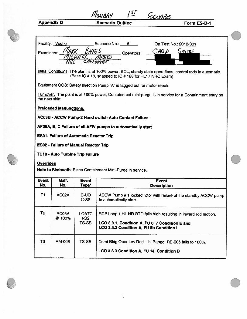
Initial Conditions: The plant is at 1 00% power, BOL, steady state operations, control rods in automatic.(Base IC # 10, snapped to IC # 186 for HL17 NRC Exam)
Equipment OOS: Safety Injection Pump “A” is tagged out for motor repair.
Turnover: The plant is at 100% power, Containment mini-purge is in service for a Containment entry onthe next shift.
Preloaded Malfunctions:
ACO3B - ACCW Pump-2 Hand switch Auto Contact Failure
AFO5A, B, C Failure of all AFW pumps to automatically start
ESO1- Failure of Automatic Reactor Trip
ESO2 - Failure of Manual Reactor Trip
TU18 - Auto Turbine Trip Failure
Overrides
Note to Simbooth: Place Containment Mini-Purge in service.
Event Malf. Event EventNo. No. Type* Description
Ti ACO2A C-UO ACCW Pump # I locked rotor with failure of the standby ACCW pumpC-SS to automatically start.
T2 RCO8A l-OATC RCP Loop 1 HL NR RTD fails high resulting in inward rod motion.@ 100% -55
TS-SS LCO 3.3.1 , Condition A, FU 6, 7 Condition E andLCO 3.3.2 Condition A, FU 5b Condition I
T3 RM-006 TS-SS Cnmt Bldg Oper Lev Rad — hi Range, RE-006 fails to 100%.
LCO 3.3.3 Condition A, FU 14, Condition B
Facility: Voatle
Examiners:
Op-Test No.: 2012-301
C,%M
S
.
0

:, \:
..1:
:1
•• •
• • • • 1.
• \••‘• .‘
0
Appendix D Scenario Outline Form ES-D-1
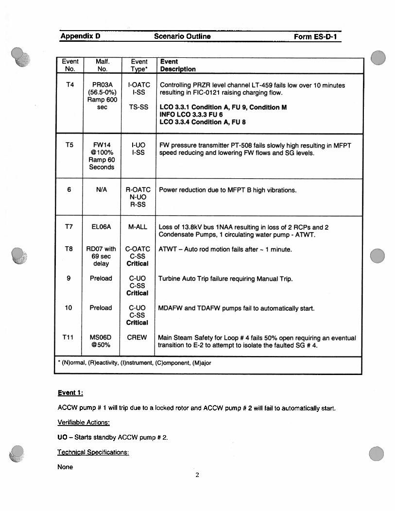
Event Maif. Event EventNo. No. Type* Description
T4 PRO3A l-OATC Controlling PRZR level channel LT-459 fails low over 10 minutes(56.5-0%) l-SS resulting in FIC-0121 raising charging flow.Ramp 600
sec TS-SS LCO 3.3.1 Condition A, FU 9, Condition MINFO LCO 3.3.3 FU 6LCO 3.3.4 Condition A, FU 8
T5 FW14 I-UO FW pressure transmitter PT-508 fails slowly high resulting in MFPT@ 1 00% I-SS speed reducing and lowering FW flows and SG levels.
Ramp 60Seconds
6 N/A R-OATC Power reduction due to MFPT B high vibrations.N-UOR-SS
T7 ELO6A M-ALL Loss of 1 3.8kV bus 1 NAA resulting in loss of 2 RCPs and 2Condensate Pumps, 1 circulating water pump - ATWT.
T8 RDO7 with C-OATC ATWT — Auto rod motion fails after 1 minute.69 sec C-SSdelay Critical
9 Preload C-UO Turbine Auto Trip failure requiring Manual Trip.C-SS
Critical
10 Preload C-UO MDAFW and TDAFW pumps fail to automatically start.C-SS
Critical
Ti 1 MSO6D CREW Main Steam Safety for Loop # 4 fails 50% open requiring an eventual@50% transition to E-2 to attempt to isolate the faulted SG # 4.
(N)ormal, (R)eactivity, (l)nstrument, (C)omponent, (M)ajor
Event 1:
ACCW pump # I will trip due to a locked rotor and ACCW pump # 2 will fail to automatically start.
Verifiable Actions:
UO — Starts standby ACCW pump #2.
.
.
Technical Specifications:
None2

.
Appendix D Scenario Outline Form ES-D-1
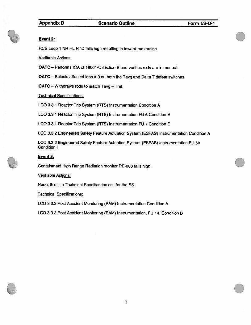
Event2: .RCS Loop 1 NR HL RTD fails high resulting in inward rod motion.
Verifiable Actions:
OATC — Performs IQA of 18001-C section B and verifies rods are in manual.
OATC — Selects affected loop # 3 on both the Tavg and Delta T defeat switches.
OATC — Withdraws rods to match Tavg — Tref.
Technical Specifications:
LCO 3.3.1 Reactor Trip System (RTS) Instrumentation Condition A
LCO 3.3.1 Reactor Trip System (RTS) Instrumentation EU 6 Condition E
LCO 3.3.1 Reactor Trip System (RTS) Instrumentation EU 7 Condition E
LCO 3.3.2 Engineered Safety Eeature Actuation System (ESEAS) Instrumentation Condition A
LCO 3.3.2 Engineered Safety Eeature Actuation System (ESEAS) Instrumentation EU 5bCondition I
Event 3:
Containment High Range Radiation monitor RE-006 fails high.
Verifiable Actions:
None, this is a Technical Specification call for the SS.
Technical Specifications:
LCO 3.3.3 Post Accident Monitoring (PAM) Instrumentation Condition A
LCO 3.3.3 Post Accident Monitoring (PAM) Instrumentation, EU 14, Condition B
03

Appendix D Scenario Outline Form ES-D-1
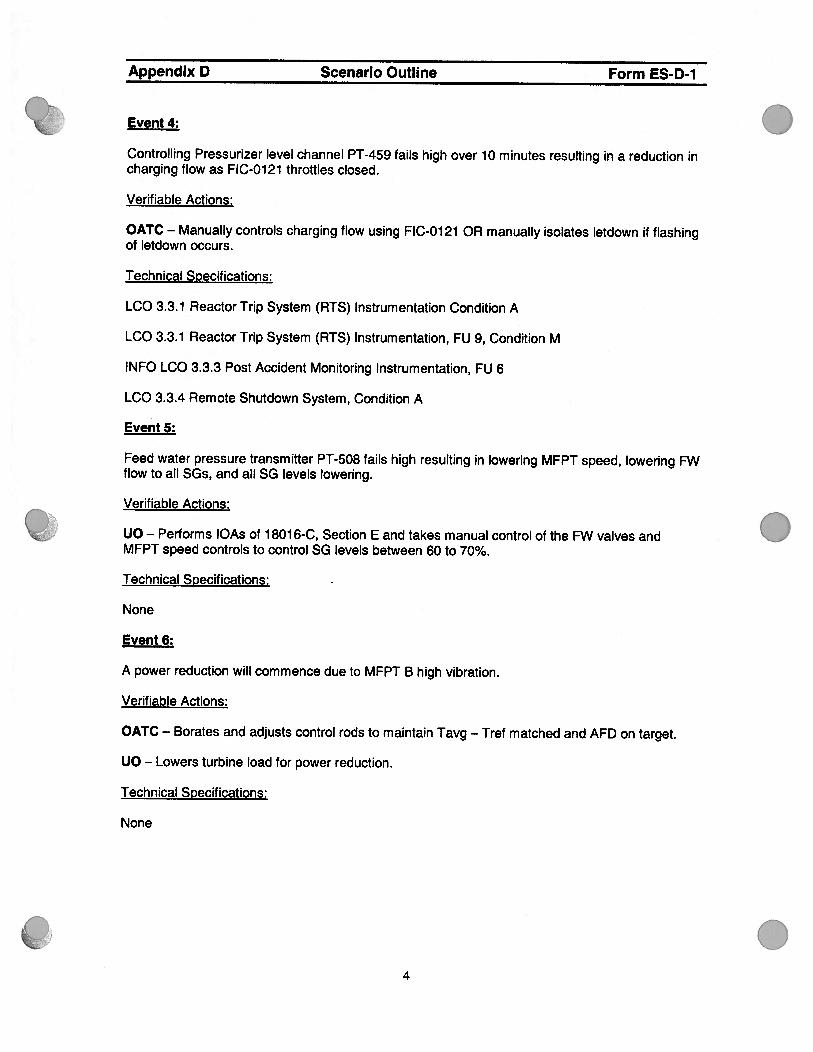
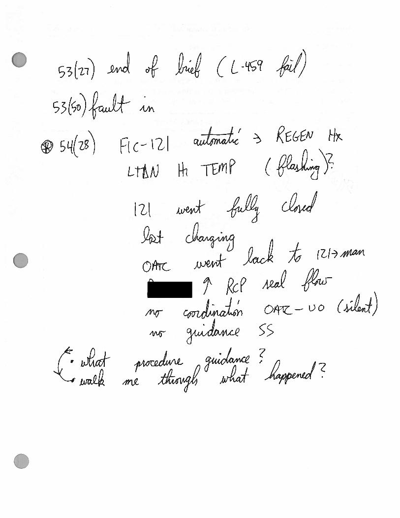
Event4: .Controlling Pressurizer level channel PT-459 fails high over 10 minutes resulting in a reduction incharging flow as FIC-0121 throttles closed.
Verifiable Actions:
OATC — Manually controls charging flow using FIC-0121 OR manually isolates letdown if flashingof letdown occurs.
Technical Specifications:
LCO 3.3.1 Reactor Trip System (RTS) Instrumentation Condition A
LCO 3.3.1 Reactor Trip System (RTS) Instrumentation, EU 9, Condition M
1NEO LCO 3.3.3 Post Accident Monitoring Instrumentation, EU 6
LCO 3.3.4 Remote Shutdown System, Condition A
Event 5:
Eeed water pressure transmitter PT-508 fails high resulting in lowering MEPT speed, lowering EWflow to all SGs, and all SG levels lowering.
Verifiable Actions:
UO — Performs IQAs of 18016-C, Section E and takes manual control of the EW valves andMEPT speed controls to control SG levels between 60 to 70%.
Technical Specifications: -
None
Event 6:
A power reduction will commence due to MEPT B high vibration.
Verifiable Actions:
OATC — Borates and adjusts control rods to maintain Tavg — Tref matched and AED on target.
UO — Lowers turbine load for power reduction.
Technical Specifications:
None
.4

Appendix D Scenario Outline Form ES-D1
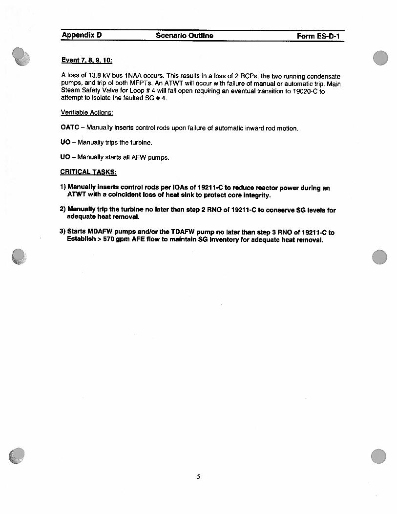
Event 7 8. 9. 1 0:
A loss of 1 3.8 kV bus 1 NAA occurs. This results n a loss of 2 RCPs, the two running condensatepumps, and trip of both MFPTs. An ATWT will occur with failure of manual or automatic trip. MainSteam Safety Valve for Loop # 4 will fail open requiring an eventual transition to 1 9020-C toattempt to isolate the faulted SG # 4.
Verifiable Actions:
OATC — Manually inserts control rods upon failure of automatic inward rod motion.
UO — Manually trips the turbine.
UO — Manually starts all AFW pumps.
CRITICAL TASKS:
1) Manually Inserts control rods per lOAs of 19211-C to reduce reactor power during anATWT with a coincident loss of heat sink to protect core integrity.
2) Manually trip the turbine no later than step 2 RNO of 19211-C to conserve SG levels foradequate heat removal.
3) Starts MDAFW pumps and/or the TDAFW pump no later than step 3 RNO of 19211-C toEstablish > 570 gpm AFE flow to maintain SG inventory for adequate heat removal.
.
.5


.
0
.
.
Appendix D Required Operator Actions Form ES-D-2
Op-Test No.: 2012-301 Scenario No.: 6
Event No. : 1
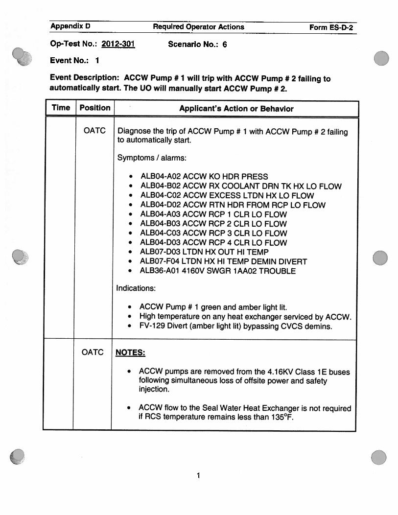
Event Description: ACCW Pump # 1 will trip with ACCW Pump # 2 failing toautomatically start. The UO will manually start ACCW Pump #2.
Time Position Applicant’s Action or Behavior
OATC Diagnose the trip of ACCW Pump # 1 with ACCW Pump # 2 failingto automatically start.
Symptoms I alarms:
. ALBO4-A02 ACCW KO HDR PRESS
. ALBO4-B02 ACCW RX COOLANT DRN TK HX LO FLOW
. ALBO4-C02 ACCW EXCESS LTDN HX LO FLOW
. ALBO4-D02 ACCW RTN HDR FROM RCP LO FLOW
. ALBO4-A03 ACCW RCP 1 CLR LO FLOW
. ALBO4-B03 ACCW RCP 2 CLR LO FLOW
. ALBO4-C03 ACCW RCP 3 CLR LO FLOW
. ALBO4-D03 ACCW RCP 4 CLR LO FLOW
. ALBO7-D03 LTDN HX OUT HI TEMP
. ALBO7-F04 LTDN HX HI TEMP DEMIN DIVERT
. ALB36-AO1 41 60V SWGR 1 AAO2 TROUBLE
Indications:
. ACCW Pump # 1 green and amber light lit.
. High temperature on any heat exchanger serviced by ACCW.
. FV-129 Divert (amber light lit) bypassing CVCS demins.
OATC NOTES:
. ACCW pumps are removed from the 4.16KV Class 1 E busesfollowing simultaneous loss of offsite power and safetyinjection.
. ACCW flow to the Seal Water Heat Exchanger is not requiredif RCS temperature remains less than 135°F.
1

0
0
(9’)oh
17
.
.
.
0
Appendix D Required Operator Actions Form ES-D-2
Op-Test No. : 201 2-301 Scenario No. : 6
Event No. : 1
Event Description: ACCW Pump # 1 will trip with ACCW Pump # 2 failing toautomatically start. The UO will manually start ACCW Pump # 2. , .
Time Position } Applicant’s Action or Behavior
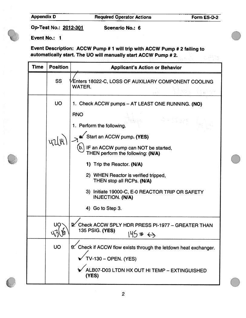
ss Enters 18022-C, LOSS OF AUXILIARY COMPONENT COOLINGWATER.
UO 1 . Check ACCW pumps - AT LEAST ONE RUNNING. (NO)
RNO
1 . Perform the following.
a/Start an ACCW pump. (YES)
IF an ACCW pump can NOT be started,THEN perform the following: (N/A)
1) Trip the Reactor. (N/A)
2) WHEN Reactor is verified tripped,THEN stop all RCPs. (N/A)
3) Initiate 1 9000-C, E-0 REACTOR TRIP OR SAFETYINJECTION. (N/A)
4) GotoStep3.
UO\ V’heck ACCW SPLY HDR PRESS P1-1977 - GREATER THAN
1Lk\135 P51G. (YES) ,
UO S4Theck if ACCW flow exists through the letdown heat exchanger.
/TV-130 — OPEN. (YES)
./ALB07-D03 LTDN HX OUT HI TEMP - EXTINGUISHED(YES)
2

.
1-H i? f7
0
.
.
.
Appendix D Required Operator Actions Form ES-D-2
Op-Test No. : 201 2-301 Scenario No. : 6
Event No. : 1
Event Description: ACCW Pump # 1 will trip with ACCW Pump # 2 failing toautomatically start. The UO will manually start ACCW Pump #2.
I Time Position Applicant’s Action or Behavior
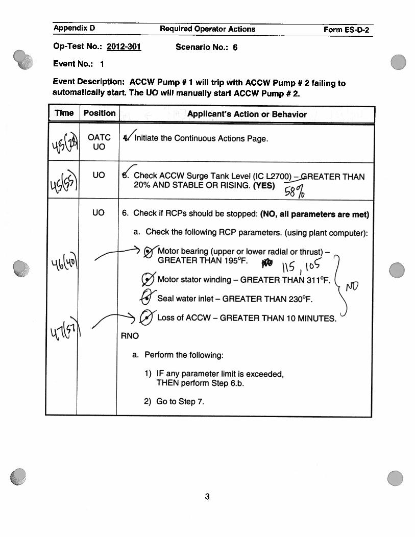
(4i: OATC 4/i’nitiate the Continuous Actions Page.‘k\y1 uc
f N uo ‘heck ACCW Surge Tank Level (IC L27OGREATER THAN
k2’ ) 20% AND STABLE OR RISING. (YES) a7
uc 6. Check if RCPs should be stopped: (NO, all parameters are met)
a. Check the following RCP parameters. (using plant computer):
‘Motor bearing (upper or lower radial or thrust) —
GREATER THAN 195°F. Ø 7c’ Motor stator winding — GREATER THAN 31 1°F. (%%
-@,Seal water inlet — GREATER THAN 230°F.
, Loss of ACCW - GREATER THAN 10 MINUTES.
RNO
a. Perform the following:
1) IF any parameter limit is exceeded,THEN perform Step 6.b.
2) Goto Step 7.
3

I
znaJ/ t/C
.
.
.
.
Appendix D Required Operator Actions Form ES-D-2
OpTest No. : 201 2-301 Scenario No. : 6
Event No. : 1
Event Description: ACCW Pump # 1 will trip with ACCW Pump # 2 failing toautomatically start. The UO wills manually start ACCW Pump # 2. .
Time Position Applicant’s Action or Behavior
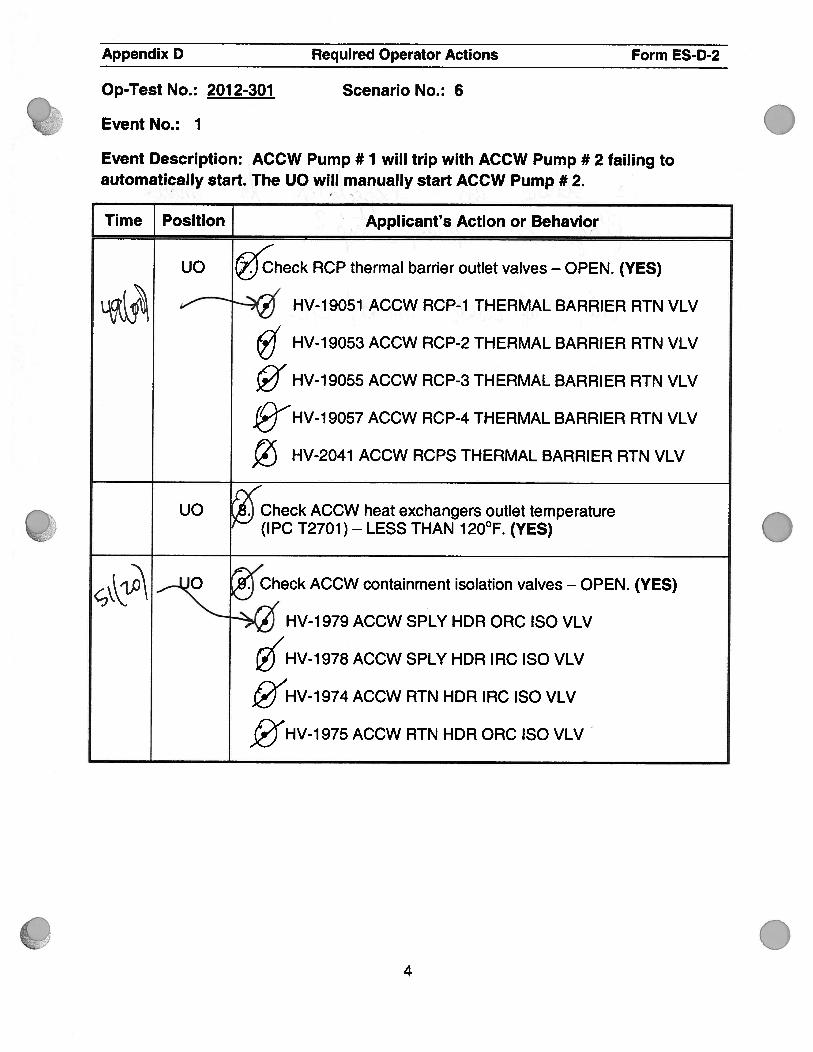
uc Ø’heck RCP thermal barrier outlet valves — OPEN. (YES)
uI% HV-19051 ACCW RCP-1 THERMAL BARRIER RTN VLV
/HV-19053 ACCW RCP-2 THERMAL BARRIER RTN VLV
/HV-19055 ACCW RCP-3 THERMAL BARRIER RTN VLV
—-
HV-19057 ACCW RCP-4 THERMAL BARRIER RTN VLV
HV-2041 ACCW RCPS THERMAL BARRIER RTN VLV
uO Check ACCW heat exchangers outlet temperature(IPC T2701 ) —
LESS THAN 1 20°F. (YES)
‘Check ACCW containment isolation valves — OPEN. (YES)
‘ Ø’ HV-1 979 ACCW SPLY HDR ORC ISO VLV
5’HV-1 978 ACCW SPLY HDR IRC ISO VLV
Ø’HV-l 974 ACCW RTN HDR IRC ISO VLV
ç”HV-1 975 ACCW RTN HDR ORC ISO VLV
4

.
C
.
.
.
Appendix D Required Operator Actions Form ES-D-2
Op-Test No. : 201 2-301 Scenario No. : 6
Event No. : 1
Event Description: ACCW Pump # 1 will trip with ACCW Pump # 2 failing toautomatically start. The UO will manually start ACCW Pump #2.
[ Time Position] Applicant’s Action or Behavior
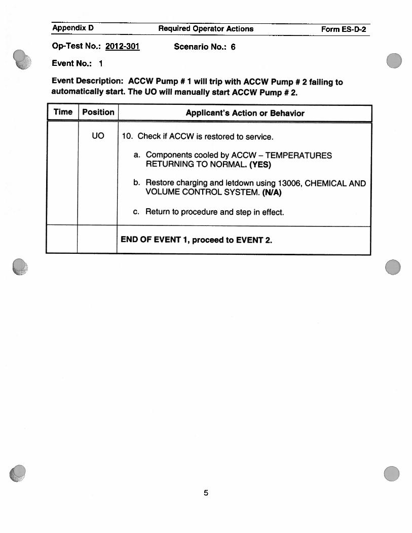
UO 10. Check if ACCW is restored to service.
a. Components cooled by ACCW — TEMPERATURESRETURNING TO NORMAL. (YES)
b. Restore charging and letdown using 13006, CHEMICAL ANDVOLUME CONTROL SYSTEM. (N/A)
c. Return to procedure and step in effect.
END OF EVENT 1, proceed to EVENT 2.
5

Appendix D Required Operator Actions Form ES-D-2
Op-Test No.: 2012-301 Scenario No.: 6
Event No.: 2
Event Description: RCS NA Temperature Instrument TE-411A Fails High (Thot) on loop # 1.This will require the OATC to perform lOAs by placing rods in MANUAL.
.The crew will then enter AOP-18001 section B “Failure of RCS Narrow Range TemperatureInstrumentation” to complete the corrective actions for this failure.
Time Position Applicant’s Action or Behavior
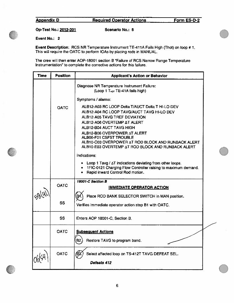
Diagnose NA Temperature Instrument Failure:(Loop 1 THOT TE-41 A fails high)
Symptoms I alarms:
OATC ALB12-A03 AC LOOP Delta T/AUCT Delta T HI-LO DEVALB12-A04 AC LOOP TAVG/AUCT TAVG HI-LO DEVALB12-A05 TAVG TREF DEVIATIONALB12-A06 OVERTEMP T ALERTALB12-B04 AUCT TAVG HIGHALB12-B06 OVERPOWER T ALERTALBO6-FO1 CSFST TROUBLEALB1O-C03 OVERPOWER T ROD BLOCK AND RUNBACK ALERTALB1O-E03 OVERTEMP T ROD BLOCK AND RUNBACK ALERT
Indications:
. Loop 1 Tavg I zT indications deviating from other loops.
. 1FIC-0121 Charging Flow Controller raising to maximum demand.
. Rapid inward Control Rod motion.
18001-C Section BOATC IMMEDIATE OPERATOR ACTION
Place ROD BANK SELECTOR SWITCH in MAN position.
55 Verifies immediate operator action step Bi with OATC.
55 Enters AOP 1 8001 -C, Section B.
OATC Subsequent Actions
Restore TAVG to program band.
%(..4L:’\OATC “elect affected loop on TS-41 2T TAVG DEFEAT SEL.
Defeats 412
.
.6
I1
)N
\
4%\fcz
41
IC
/-
c,oC
Ne
e
Appendix D Required Operator Actions Form ESD-2
OpTest No.: 201 2-301 Scenario No.: 6
Event No.: 2
Event Description: RCS NR Temperature Instrument TE-411A Fails High (Thot) on loop # 1.This will require the OATC to perform 1OAs by placing rods in MANUAL.
The crew will then enter AOP-18001 section B “Failure of RCS Narrow Range TemperatureInstrumentation” to complete the corrective actions for this failure.
Applicant’s Action or Behavior
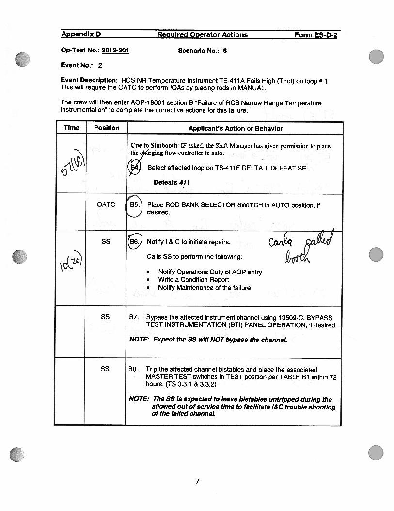
Cue to Simbooth: IF asked, the Shift Manager has given permission to placethe c arging flow controller in auto.
4 Select affected loop on TS-41 1 F DELTA T DEFEAT SEL.
Defeats 411
Place ROD BANK SELECTOR SWITCH in AUTO position, ifdesired.
Notify I & C to initiate repairs.
Calls SS to perform the following:
. Notify Operations Duty of AOP entry
. Write a Condition Report
. Notify Maintenance of the failure
B7. Bypass the affected instrument channel using 1 3509-C, BYPASSTEST INSTRUMENTATION (BTI) PANEL OPERATION, if desired.
NOTE: Expect the SS will NOT bypass the channeL
Trip the affected channel bistables and place the associatedMASTER TEST switches in TEST position per TABLE Bi within 72hours. (TS 3.3.1 & 3.3.2)
The SS is expected to leave bistables untripped during theallowed out of service time to facilltate l&C trouble shootingof the failed channeL
7
Gb0
(
(%J
. <V
frII’
Appendix D Required Operator Actions Form ES-D-2
Op-Test No.: 201 2-301 Scenario No.: 6
Event No.: 2
Event Description: RCS NR Temperature Instrument TE-41 1A Fails High (Thot) on loop # 1.This will require the OATC to perform lOAs by placing rods in MANUAL.
The crew will then enter AOP-18001 section B “Failure of RCS Narrow Range TemperatureInstrumentation” to complete the corrective actions for this failure.
Time Position Applicant’s Action or Behavior
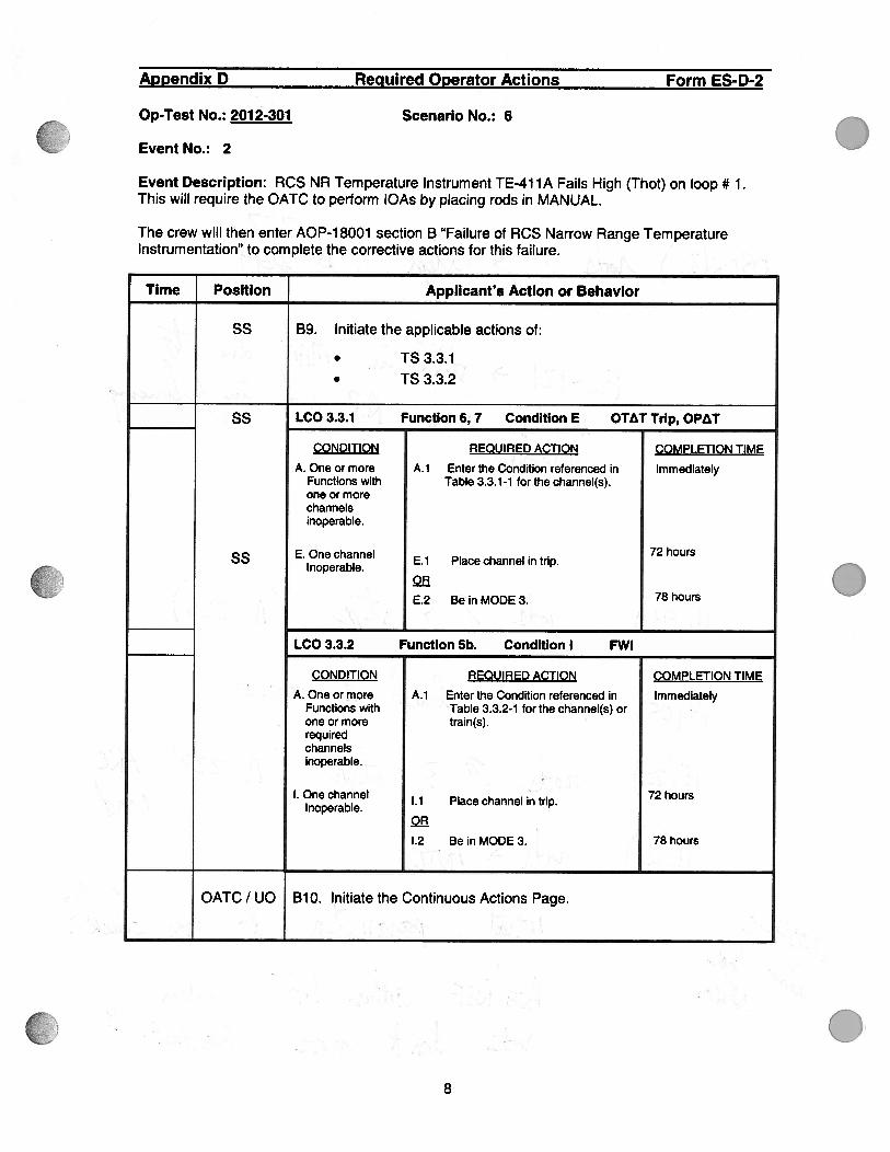
ss B9. Initiate the applicable actions of:
. TS3.3.1
. TS 3.3.2
ss LCO 3.3.1 Function 6, 7 Condition E OTAT Trip, OPAT
CONDITION REQUIRED ACTION COMPLETION TIME
A. One or more A.1 Enter the Condition referenced in ImmediatelyFunctions with Table 3.3.1-1 for the channel(s).one or morechannelsinoperable.
ss E. One channel E.1 Place channel in trip.72 hours
Inoperable.OR
. E.2 Be in MODE 3. 78 hours
LCO 3.3.2 Function 5b. Condition I FWI
CONDITION REQUIRED ACTION COMPLETION TIME. .
A. One or more A.1 Enter the Condition referenced in ImmediatelyFunctions with Table 3.3.2-1 for the channel(s) orone or more train(s).requiredchannels
, .. inoperable.
I. One channel •• .1 Place channel in trip. 72 hoursInoperable.
OR
1.2 Be in MODE 3. 78 hours
OATC I UO BlO. Initiate the Continuous Actions Page.
08

Appendix D Required Operator Actions Form ES-D-2
Op-Test No.: 2012-301 Scenario No.: 6
Event No.: 2
Event Description: RCS NR Temperature Instrument TE-41 1A Fails High (Thot) on loop # 1.This will require the OATC to perform lOAs by placing rods in MANUAL.
The crew will then enter AOP-18001 section B “Failure of RCS Narrow Range TemperatureInstrumentation” to complete the corrective actions for this failure.
Time Position Applicant’s Action or Behavior
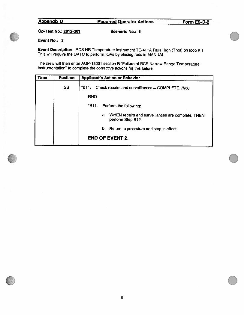
SS B1 1. Check repairs and surveillances — COMPLETE. (NO)
RNO
*B1 1. Perform the following:
a. WHEN repairs and surveillances are complete, THENperform Step B12.
b. Return to procedure and step in effect.
END OF EVENT 2.
.
.
09

.
.
0
Appendix D Required Operator Actions Form ES-D-2
Op-Test No.: 201 2-301 Scenario No.: 6
Event No.: 3
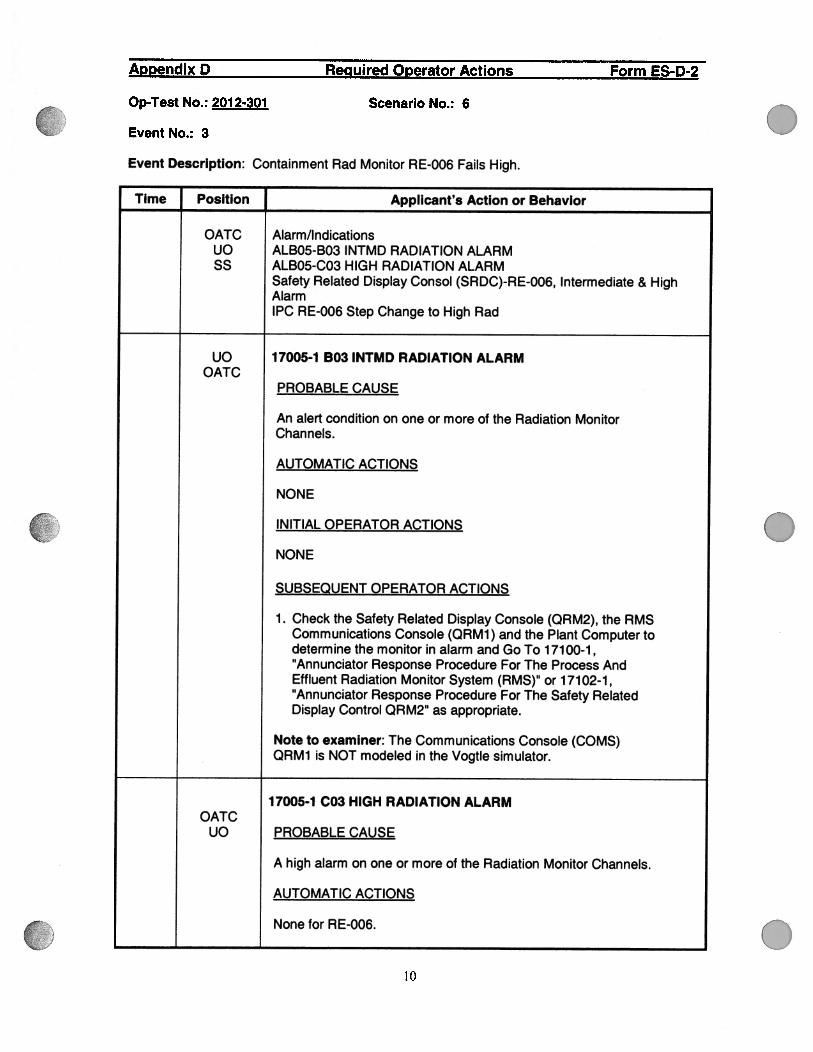
Event Description: Containment Rad Monitor RE-006 Fails High.
Time Position Applicant’s Action or Behavior
OATC Alarm/Indicationsuo ALBO5-B03 INTMD RADIATION ALARMss ALBO5-C03 HIGH RADIATION ALARM
Safety Related Display Consol (SRDC)-RE-006, Intermediate & HighAlarmIPC RE-006 Step Change to High Rad
uO 17005-1 B03 INTMD RADIATION ALARMOATC
PROBABLE CAUSE
An alert condition on one or more of the Radiation MonitorChannels.
AUTOMATIC ACTIONS
NONE
INITIAL OPERATOR ACTIONS
NONE
SUBSEQUENT OPERATOR ACTIONS
1 . Check the Safety Related Display Console (QRM2), the RMSCommunications Console (QRM1) and the Plant Computer todetermine the monitor in alarm and Go To 17100-1,“Annunciator Response Procedure For The Process AndEffluent Radiation Monitor System (RMS)” or 17102-1,“Annunciator Response Procedure For The Safety RelatedDisplay Control QRM2” as appropriate.
Note to examiner: The Communications Console (COMS)QRM1 is NOT modeled in the Vogtle simulator.
17005-1 C03 HIGH RADIATION ALARMOATC
UO PROBABLE CAUSE
A high alarm on one or more of the Radiation Monitor Channels.
AUTOMATIC ACTIONS
None for RE-006.
10

II
ac)
(j1l)-LL
0
0
.
0
Appendix D Required Operator Actions Form ES-D-2
Op-Test No.: 201 2-301 ScenarIo No.: 6
Event No.: 3
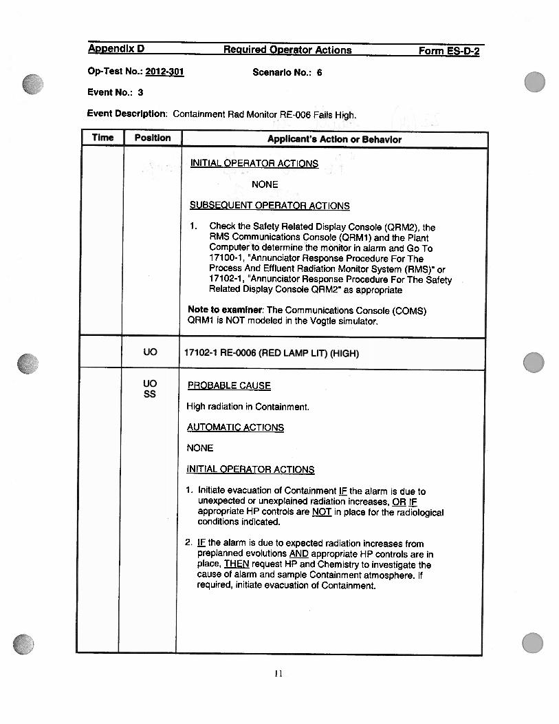
Event Description: Containment Rad Monitor RE-006 Fails High.
Time Position Applicant’s Action or Behavior
S
INITIAL OPERATOR ACTIONS
NONE
SUBSEQUENT OPERATOR ACTIONS
1 . Check the Safety Related Display Console (QRM2), theRMS Communications Console(QRM1) and the PlantComputer to determine the monitor in alarm and Go To1 71 00-1 , ‘Annunciator Response Procedure For TheProcess And Effluent Radiation Monitor System (RMS)” or1 71 02-1 , ‘Annunciator Response Procedure For The SafetyRelated Display Console QRM2” as appropriate
Note to examiner: The Communications Console (COMS)QRM1 is NOT modeled in the Vogtle simulator.
UO 17102-1 RE-0006 (RED LAMP LIT) (HIGH)
UO PROBABLE CAUSESS
High radiation in Containment.
AUTOMATIC ACTIONS
NONE
INITIAL OPERATOR ACTIONS
1 . Initiate evacuation of Containment IF the alarm is due tounexpected or unexplained radiation increases, OR IFappropriate HP controls are 4QI in place for the radiologicalconditions indicated.
2. jf the alarm is due to expected radiation increases frompreplanned evolutions appropriate HP controls are inplace, THEN request HP and Chemistry to investigate thecause of alarm and sample Containment atmosphere. ifrequired, initiate evacuation of Containment.
11

.
S
.
.
Appendix D Required Operator Actions Form ES-D-2
Op-Test No.: 2012-301 ScenarIo No.: 6
Event No.: 3
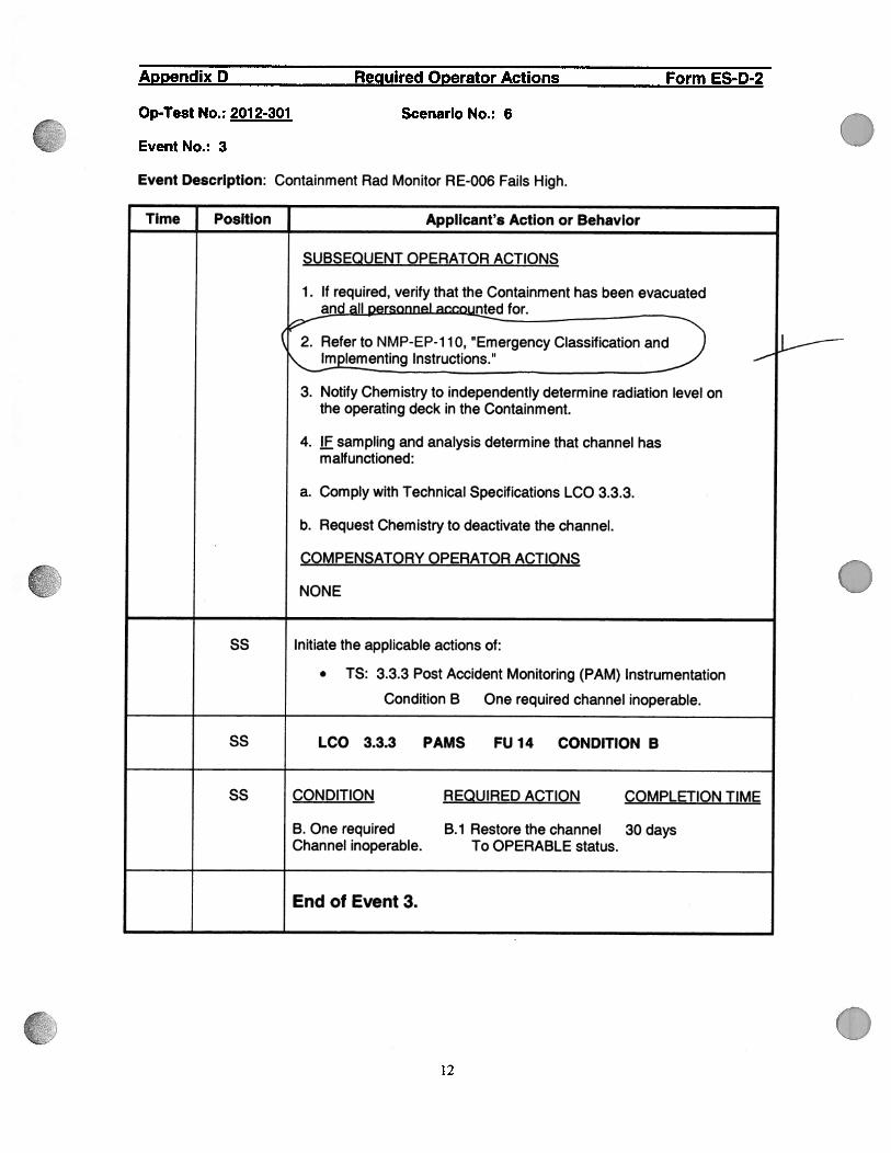
Event Description: Containment Rad Monitor RE-006 Fails High.
Time Position Applicant’s Action or Behavior
SUBSEQUENT OPERATOR ACTIONS
1 . If required, verify that the Containment has been evacuatedand II nted for.
2. Refer to NMP-EP-1 1 0, “Emergency Classification andImplementing Instructions.”
3. Notify Chemistry to independently determine radiation level onthe operating deck in the Containment.
4. IF sampling and analysis determine that channel hasmalfunctioned:
a. Comply with Technical Specifications LCO 3.3.3.
b. Request Chemistry to deactivate the channel.COMPENSATORY
OPERATOR ACTIONS
NONE
55 Initiate the applicable actions of:
. TS: 3.3.3 Post Accident Monitoring (PAM) Instrumentation
Condition B One required channel inoperable.
SS LCO 3.3.3 PAMS FU 14 CONDITION B
SS CONDITION REQUIRED ACTION COMPLETION TIME
B. One required B.1 Restorethechannel 30 daysChannel inoperable. To OPERABLE status.
End of Event 3.
12

9AJVf
Appendix D Required Operator Actions Form ES-D-2
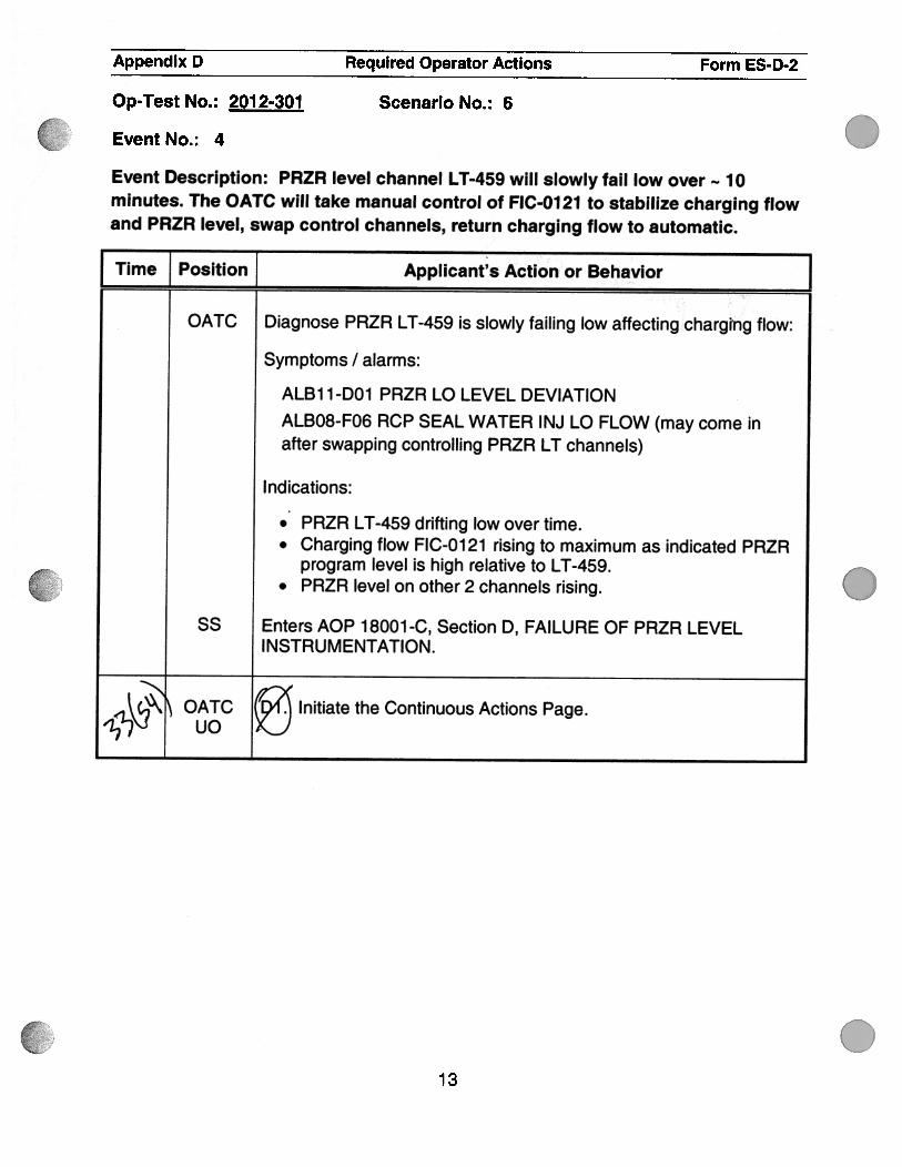
Event No.: 4
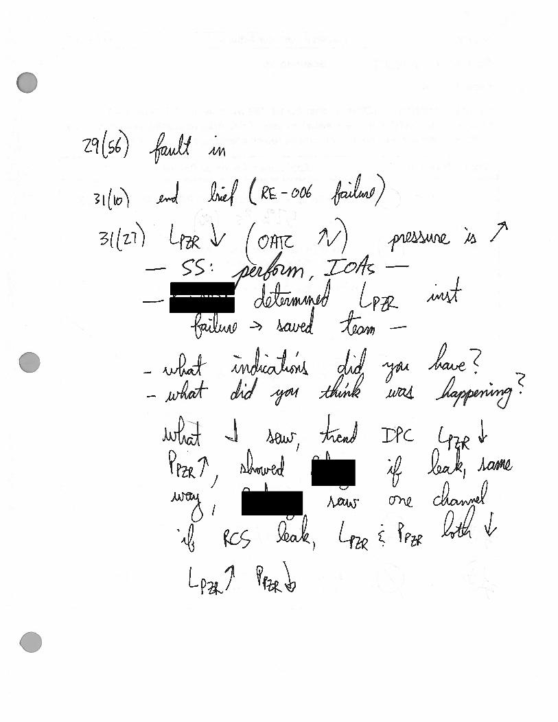
Event Description: PRZR level channel LT-459 will slowly fail low over 10minutes. The OATC will take manual control of F1C-0121 to stabilize charging flowand PRZR level, swap control channels, return charging flow to automatic.
I Time Position Applicant’s Action or Behavior JOATC Diagnose PRZR LT-459 is slowly failing low affecting charging flow:
Symptoms I alarms:
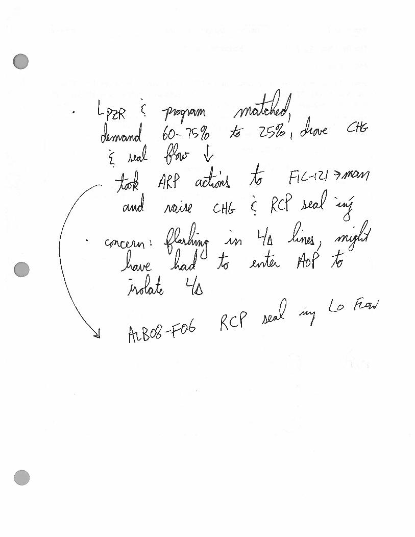
ALB1 1 -DOl PRZR LO LEVEL DEVIATIONALBO8-F06 RCP SEAL WATER INJ LO FLOW (may come inafter swapping controlling PRZR LT channels)
Indications:
.. PRZR LT-459 drifting low over time.• Charging flow FIC-0121 rising to maximum as indicated PRZR
program level is high relative to LT-459.. PRZR level on other 2 channels rising.
SS Enters AOP 18001-C, Section D, FAILURE OF PRZR LEVELINSTRUMENTATION.
c4\ OATC (94.’ Initiate the Continuous Actions Page.2LN UO XJ
tOp-Test No.: 2012-301 Scenario No.: 6
.
.13
29 (si)
3((z])
&ef
Zoilc(Q
c
G/41r
‘4
2
)Lrn
DPC
Appendix D Required Operator Actions Form ES-D-2
Op-Test No.: 2012-301 Scenario No.: 6
Event No.: 4
Event Description: PRZR level channel LT-459 will slowly fail low over 10minutes. The OATC will take manual control of FIC-0121 to stabilize charging flowand PRZR level, swap control channels, return charging flow to automatic.
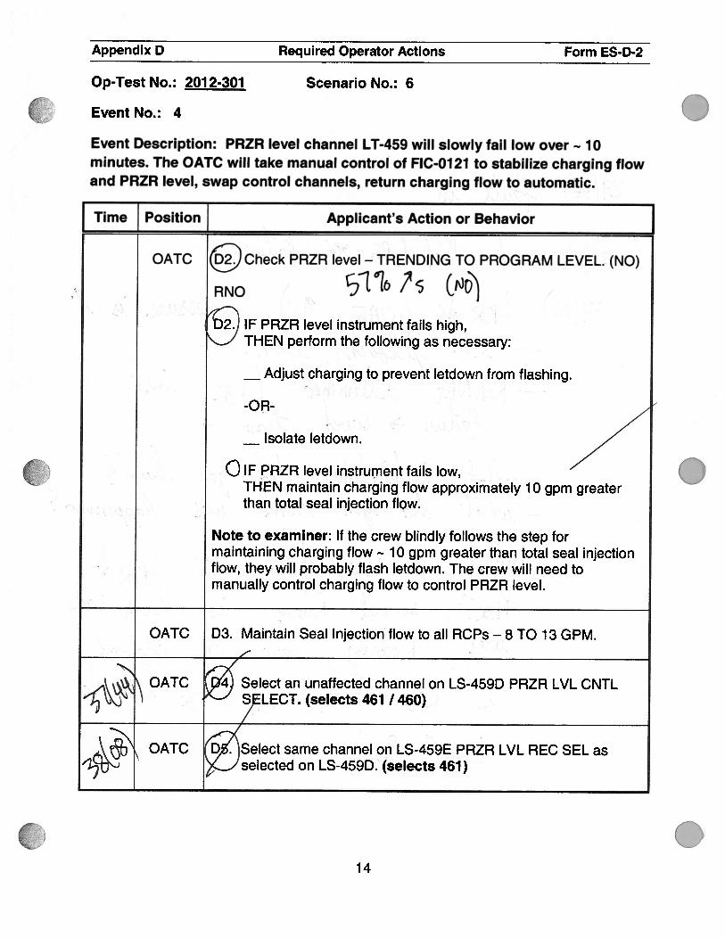
Time Position ] Applicant’s Action or Behavior JOATC Check PRZR level - TRENDING TO PROGRAM LEVEL. (NO)
,1 RNO 7s C&6’j‘ ...
2. IF PRZR level instrument fails hih,THEN perform the following as necessary:
. .‘ —Adjustcharging to prevent letdown from flashing.
—Isolate letdown.
a IF PRZR level instrument fails low,% THEN maintain charging flow approximately 10 gpm greater
. : •
than total seal injection flow.
Note to examiner: If the crew blindly follows the step formaintaining charging flow 1 0 gpm greater than total seal injectionflow, they will probably flash letdown. The crew will need tomanually control charging flow to control PRZR level.
OATC D3. Maintain Seal Injection flow to all RCPs — 8 TO 1 3 GPM.
“ \‘.\ ‘OATC 4 Select an unaffected channel on LS-459D PRZR LVL CNTL
-1.’%J S LECT. (selects 461 I 460)
OATC D . Select same channel on LS-459E PRZR LVL REC SEL as-1j-’ selected on LS-459D. (selects 461)
0
014
I
I
.o
.
Appendix D Required Operator Actions Form ES-D-2
Op-Test No.: 2012-301 Scenario No.: 6
Event No.: 4
Event Description: PRZR level channel LT-459 will slowly fail low over 10minutes. The OATC will take manual control of FIC-0121 to stabilize charging flowand PRZR level, swap control channels, return charging flow to automatic.
Time Position Applicant’s Action or Behavior
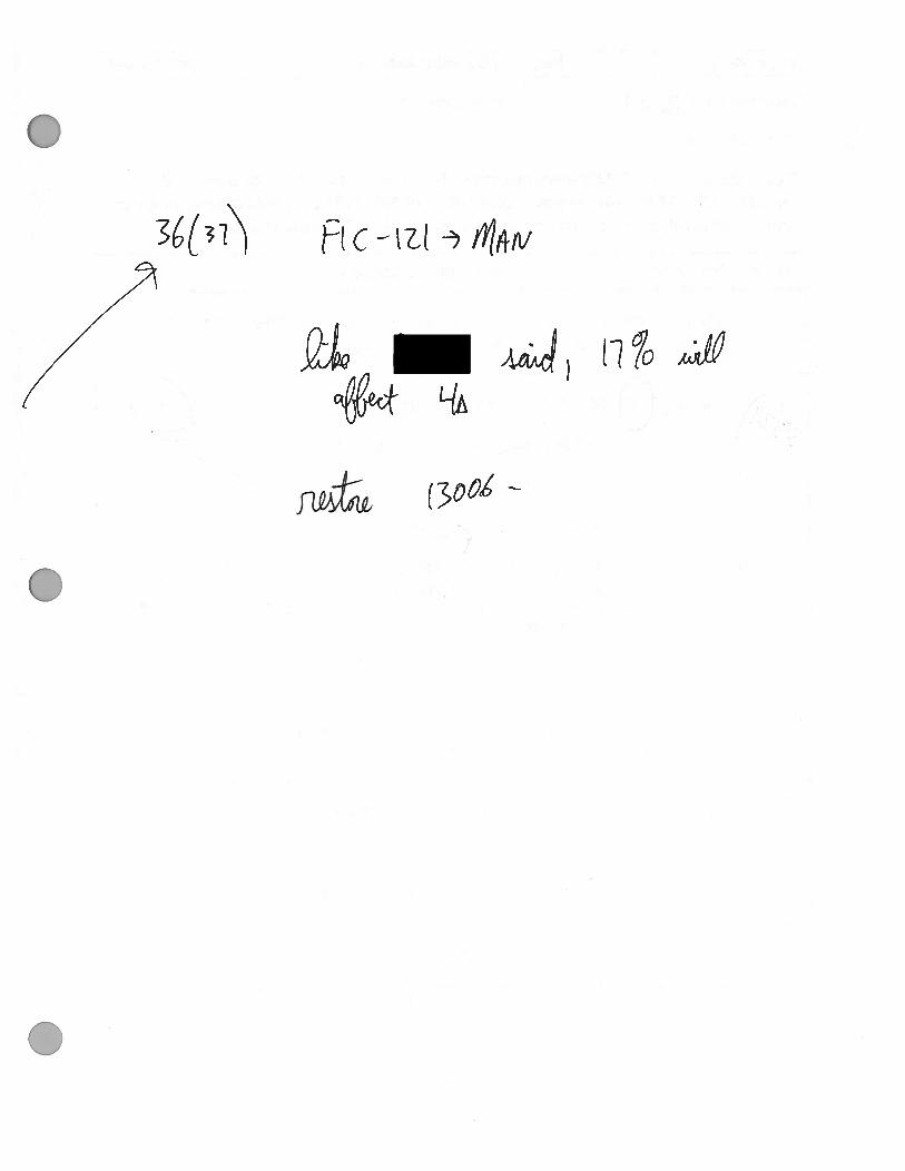
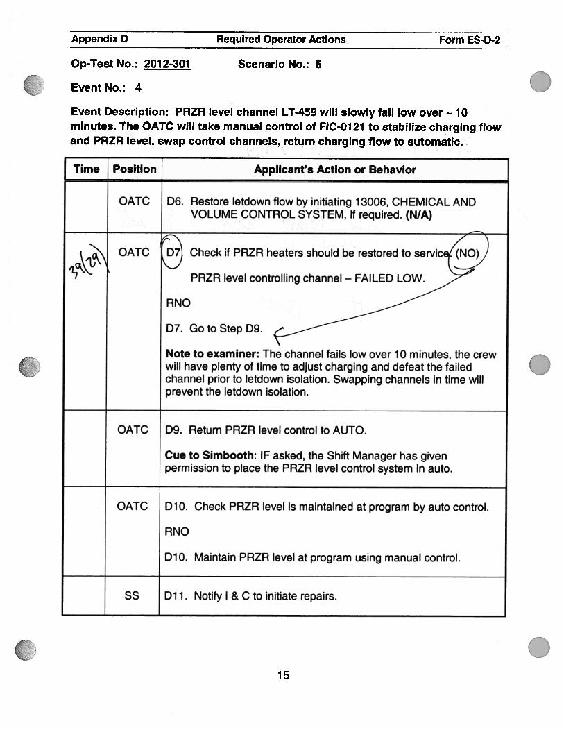
OATC D6. Restore letdown flow by initiating 1 3006, CHEMICAL ANDVOLUMECONTROL SYSTEM, if required. (N/A)
c7sQATC : Check if PRZR heaters should be restored to servic .
17PRZR level controlling channel — FAILED LOW.
RNO
D7. GotoStepD9.
Note to examiner: The channel fails low over 10 minutes, the crewwill have plenty of time to adjust charging and defeat the failedchannel prior to letdown isolation. Swapping channels in time willprevent the letdown isolation.
OATC D9. Return PRZR level control to AUTO.
Cue to Simbooth: IF asked, the Shift Manager has givenpermission to place the PRZR level control system in auto.
OATC D1O. Check PRZR level is maintained at program by auto control.
RNO
D1O. Maintain PRZR level at program using manual control.
SS Dli. Notify I & C to initiate repairs.
.15

Appendix D Required Operator Actions Form ES-D-2
Op-Test No.: 2012-301
Event No.: 4
Scenario No.: 6
Event Description: PRZR level channel LT-459 will slowly fail low over 10minutes. The OATC will take manual control of F1C-01 21 to stabilize charging flowand PRZR level, swap control channels, return charging flow to automatic.
Time]_Position
Applicant’s Action or Behavior
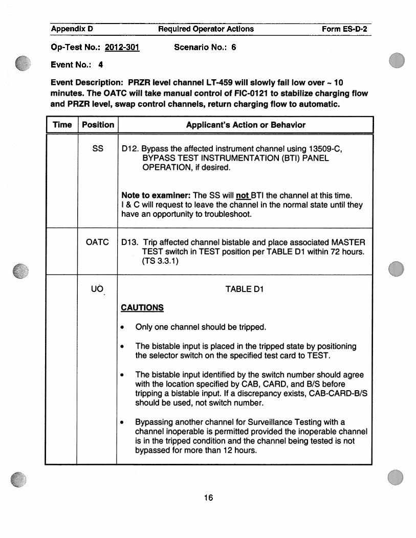
ss D12. Bypass the affected instrument channel using 13509-C,BYPASS TEST INSTRUMENTATION (BTI) PANELOPERATION, if desired.
Note to examiner: The 55 will notBTI the channel at this time.I & C will request to leave the channel in the normal state until theyhave an opportunity to troubleshoot.
OATC D13. Trip affected channel bistable and place associated MASTERTEST switch in TEST position per TABLE Dl within 72 hours.(TS 3.3.1)
UC TABLE Dl
CAUTIONS
. Only one channel should be tripped.
. The bistable input is placed in the tripped state by positioningthe selector switch on the specified test card to TEST.
. The bistable input identified by the switch number should agreewith the location specified by CAB, CARD, and B/S beforetripping a bistable input. If a discrepancy exists, CAB-CARD-B/Sshould be used, not switch number.
. Bypassing another channel for Surveillance Testing with achannel inoperable is permitted provided the inoperable channelis in the tripped condition and the channel being tested is notbypassed for more than 12 hours.
.
0
16

.
Appendix D Required Operator Actions Form ES.D-2
Op-Test No.: 2012-301 Scenario No.: 6
Event No.: 4
Event Description: PRZR level channel LT-459 will slowly fail low over 10minutes. The OATC will take manual control of FIC-0121 to stabilize charging flowand PRZR level, swap control channels, return charging flow to automatic.
Time Position Applicant’s Action or Behavior
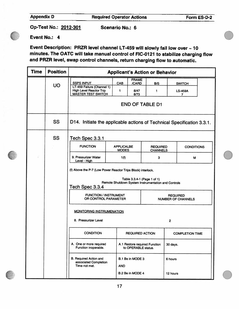
I FRAME[PSINPUT CAB /CARD B/S SWITCHuo LT-459 Failure (Channel 1)
High Level Reactor Trip I 8/47 1 LS-459AMASTER TEST SWITCH 8/73 7
END OF TABLE Dl
ss D14. Initiate the applicable actions of Technical Specification 3.3.1.
SS Tech Spec3.3.l
FUNCTION APPLICALBE REQUIRED CONDITIONSMODES CHANNELS
9. Pressurizer Water 1(f) 3 MLevel - High
(f) Above the P-7 (Low Power Reactor Trips Block) interlock.
Table 3.3.4-1 (Page 1 of 1)Remote Shutdown System Instrumentation and Controls
Tech Spec 3.3.4
FUNCTION / INSTRUMENT REQUIREDOR CONTROL PARAMETER NUMBER OF CHANNELS
MONITORING INSTRUMENATION
8. Pressurizer Level 2
CONDITION REQUIRED ACTION COMPLETION TIME
A. One or more required A.1 Restore required Function 30 days.Function inoperable. to OPERABLE status.
B. Required Action and B.1 Be in MODE 3 6 hoursassociated CompletionTimenotmet. AND
B.2 Be in MODE 4 12 hours
17

Appendix D Required Operator Actions Form ES-D-2
Op-Test No.: 2012-301 Scenario No.: 6
Event No.: 4
Event Description: PRZR level channel LT-459 will slowly fail low over 10minutes. The OATC will take manual control of FIC-Ol 21 to stabilize charging flowand PRZR level, swap control channels, return charging flow to automatic.
Time Position Applicant’s Action or Behavior
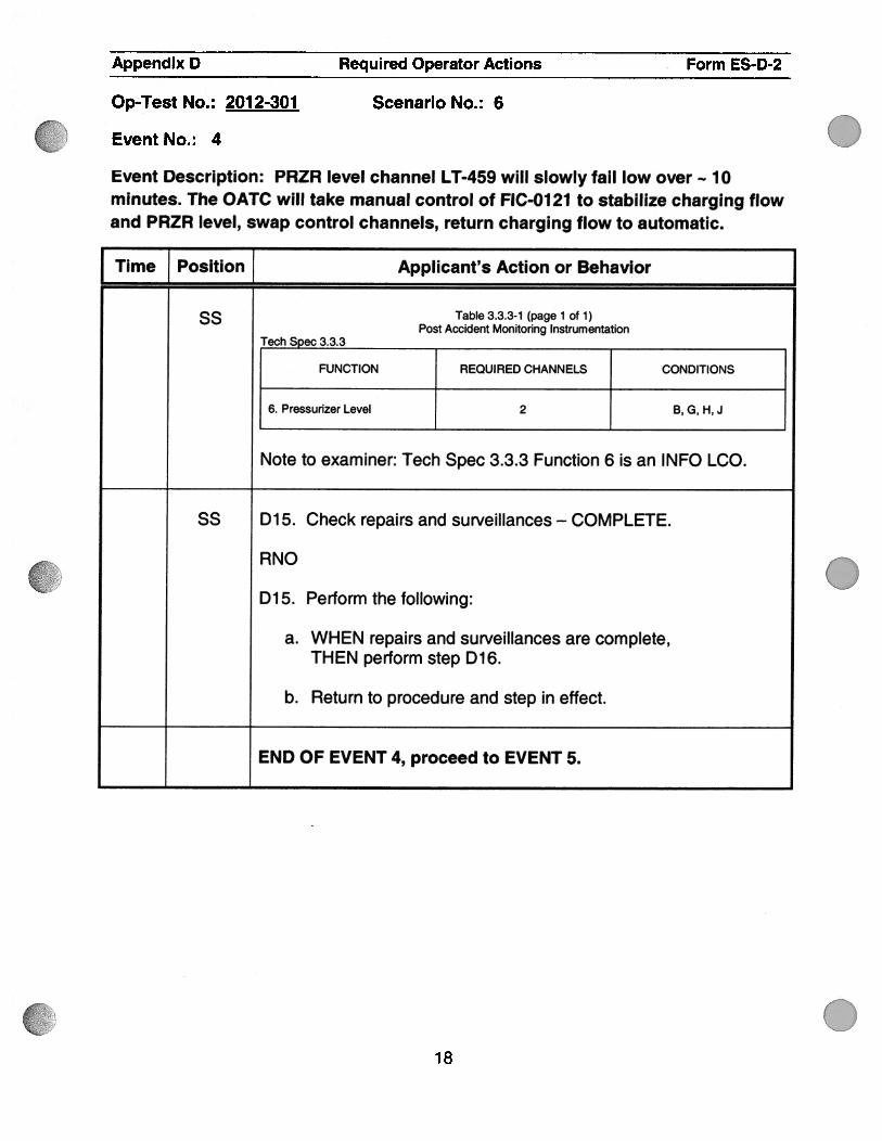
ss Table 3.3.3-1 (page 1 of 1)Post Accident Monitoring Instrumentation
Tech Spec 3.3.3
FUNCTION REQUIRED CHANNELS CONDITIONS
6. Pressurizer Level 2 B, G, H, J
Note to examiner: Tech Spec 3.3.3 Function 6 is an INFO LCO.
55 D15. Check repairs and surveillances — COMPLETE.
RNO
D15. Perform the following:
a. WHEN repairs and surveillances are complete,THEN perform step D16.
b. Return to procedure and step in effect.
END OF EVENT 4, proceed to EVENT 5.
018

Appendix D Required Operator Actions Form ES-D-2
Time Position ] Applicant’s Action or Behavior
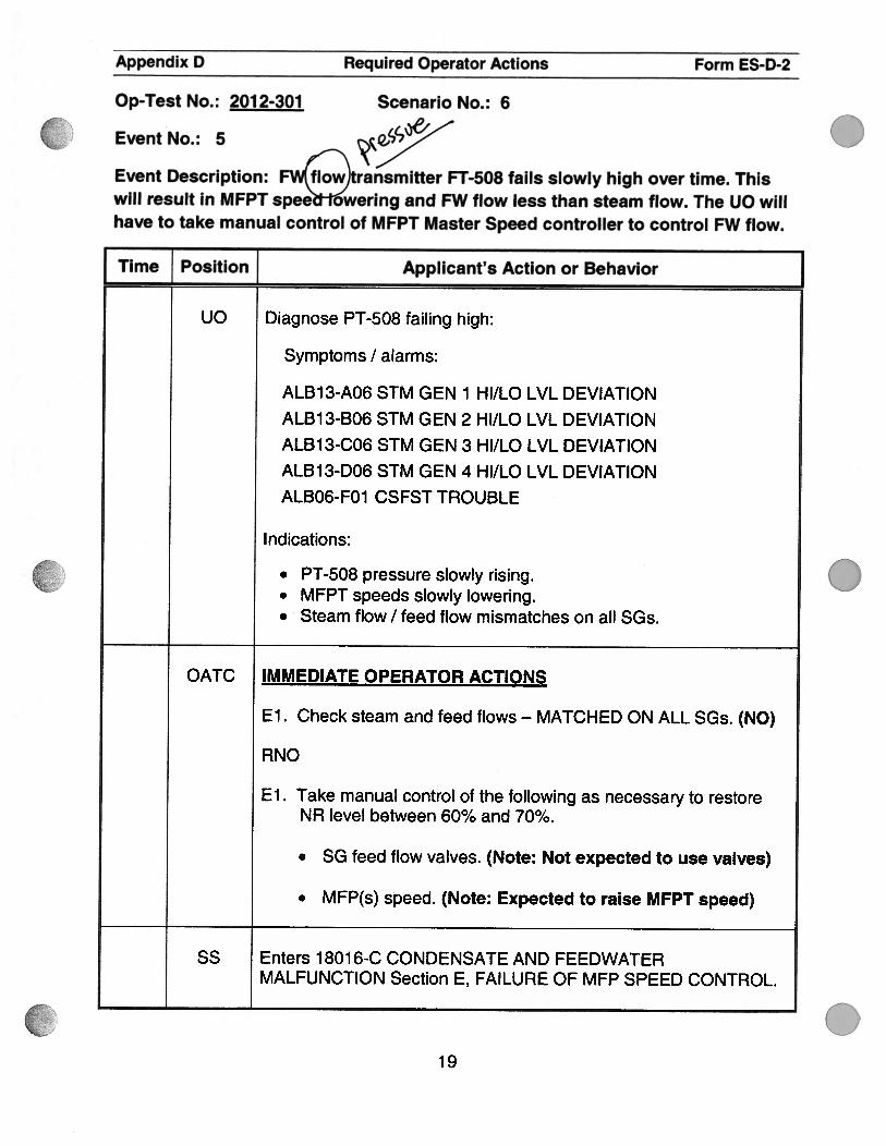
Uc Diagnose PT-508 failing high:
Symptoms I alarms:
ALB13-A06 STM GEN 1 HI/LO LVL DEVIATIONALB13-B06 STM GEN 2 HI/LO LVL DEVIATIONALB13-C06 STM GEN 3 HI/LO LVL DEVIATIONALB13-D06 STM GEN 4 HI/LO LVL DEVIATIONALBO6-FO1 CSFST TROUBLE
Indications:
. PT-508 pressure slowly rising.
. MFPT speeds slowly lowering.
. Steam flow I feed flow mismatches on all SGs.
OATC IMMEDIATE OPERATOR ACTIONS
El . Check steam and feed flows — MATCHED ON ALL SGs. (NO)
RNO
El . Take manual control of the following as necessary to restoreNR level between 60% and 70%.
. SG feed flow valves. (Note: Not expected to use valves)
. MFP(s) speed. (Note: Expected to raise MFPT speed)
SS Enters 18016-C CONDENSATE AND FEEDWATERMALFUNCTION Section E, FAILURE OF MFP SPEED CONTROL.
tOp-Test No. : 201 2-301 Scenario No. : 6
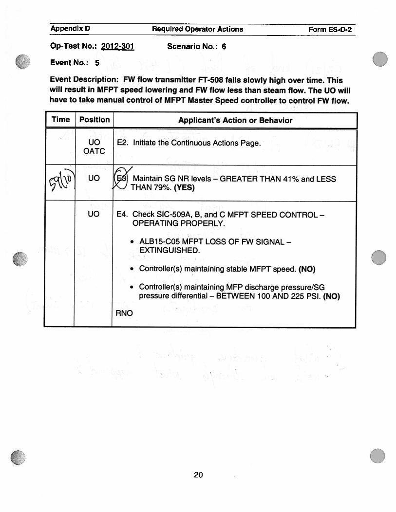
EventNo.: 5
Event Description: F flow transmitter FT-508 fails slowly high over time. Thiswill result in MFPT spee owering and FW flow less than steam flow. The UO willhave to take manual control of MFPT Master Speed controller to control FW flow.
.
.
19
\jN
z1
.. 0
‘jT
h
Appendix D Required Operator Actions Form ES-D-2
Op-Test No.: 2012-301
Event No.: 5
Scenario No.: 6
Event Description: FW flow transmitter FT-508 fails slowly high over time. Thiswill result in MFPT speed lowering and FW flow less than steam flow. The UO willhave to take manual control of MFPT Master Speed controller to control FW flow.
I Time Position Applicant’s Action or Behavior
. . uo E2. Initiate the Continuous Actions Page. . .
OATC
s rV(‘ct\: uO cj Maintain SG NR levels - GREATER THAN 41% and LESS‘2 THAN 79%. (YES)
uo E4. Check SlC-509A, B, and C MFPT SPEED CONTROL -
OPERATING PROPERLY.
. ALB15-C05 MFPT LOSS OF FW SIGNAL -
.; EXTINGUISHED.
. Controller(s) maintaining stable MFPT speed. (NO)
• Controller(s) maintaining MFP discharge pressure/SGpressure differential — BETWEEN 100 AND 225 PSI. (NO)
RNO
.
.
0
20
.0
4” 7c
HL
L
I
N
Appendix D Required Operator Actions Form ES.D.2
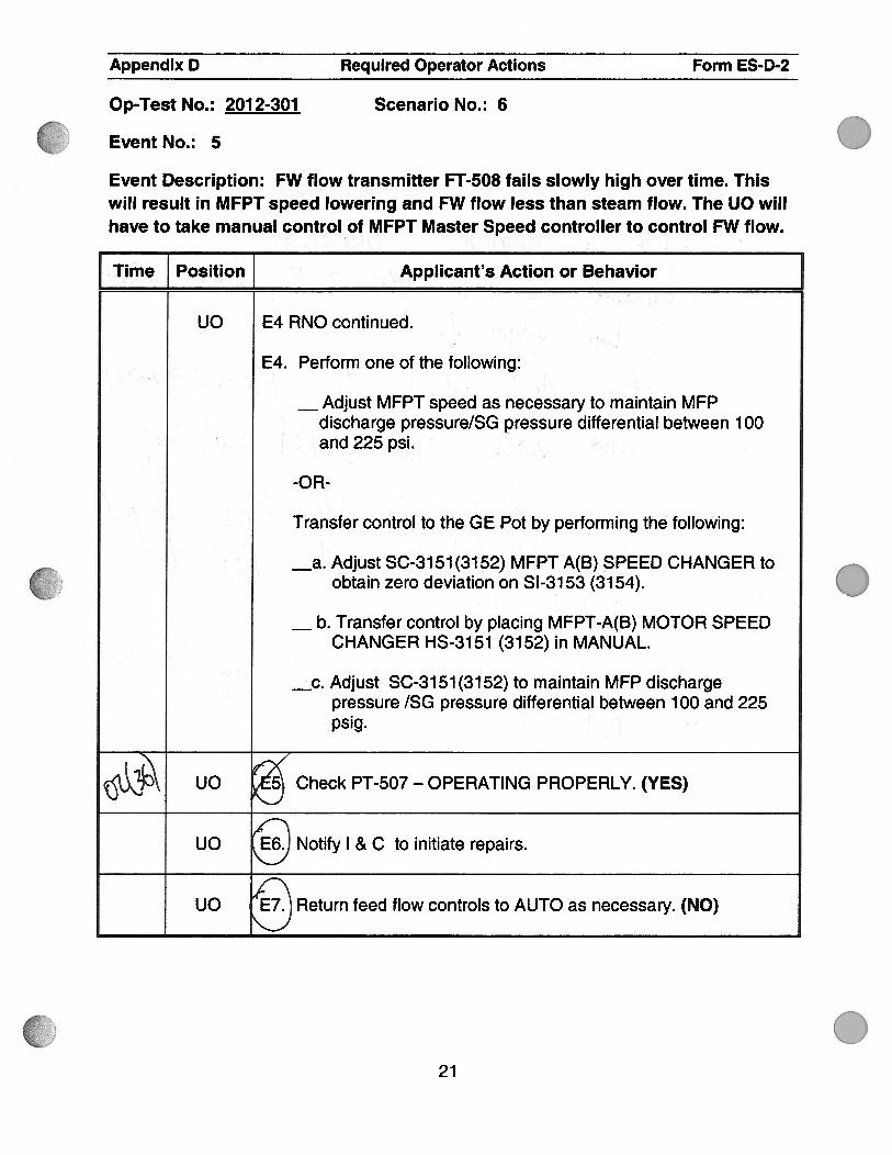
Event No.: 5
Event Description: FW flow transmitter FT-508 fails slowly high over time. Thiswill result in MFPT speed lowering and FW flow less than steam flow. The UO willhave to take manual control of MFPT Master Speed controller to control FW flow.
Time Position Applicant’s Action or Behavior Juo E4 RNO continued.
E4. Perform one of the following:
—Adjust MFPT speed as necessary to maintain MFPdischarge pressure/SG pressure differential between 100and 225 psi.
-OR-
.. ,.. ::;
Transfer control to the GE Pot by pertorming the following:. .. : a. Adjust SC-3151(3152) MFPT A(B) SPEED CHANGER to
%
obtain zero deviation on 51-31 53 (3154).
—b. Transfer control by placing MFPT-A(B) MOTOR SPEED
CHANGER HS-3151 (3152) in MANUAL.
Adjust SC-3151(3152) to maintain MFP dischargepressure /SG pressure differential between 1 00 and 225psig.
%$4.L UO g’ Check PT-507 — OPERATING PROPERLY. (YES)
UO Notify I & C to initiate repairs.
UO E7. Return feed flow controls to AUTO as necessary. (NO)
C)Op-Test No.: 2012-301 Scenario No.: 6
.
0
021

Appendix D Required Operator Actions Form ES-D-2
Op-Test No.: 2012-301
Event No.: 5
Scenario No.: 6
Event Description: FW flow transmitter FT-508 fails slowly high over time. Thiswill result in MFPT speed lowering and FW flow less than steam flow. The UO willhave to take manual control of MFPT Master Speed controller to control FW flow.
Time Position Applicant’s Action or Behavior
SS E8. Check repairs and surveillances — COMPLETE. (NO)
RNO
E8. Perform the following:
a. WHEN repairs and surveillances are complete,THEN perform Step E9.
b. Return to procedure and step in effect.
END OF EVENT 5, proceed to EVENT 6.
.
.
022

Appendix D Required Operator Actions Form ES-D-2
Op-Test No.: 2012-301 Scenario No.: 6
Event No.: 6, actions per ARP 1701 5-05
Event Description: MFPT B turbine vibration will rise to > 6 mils requiring entryinto 18013-C Rapid Power Reduction and trip of MFPT B.
Time Position Applicant’s Action or Behavior
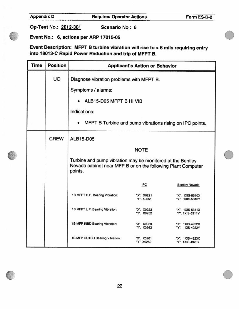
uo Diagnose vibration problems with MFPT B.
Symptoms I alarms:
. ALB15-D05 MFPT B HI VIB
Indications:
. MFPT B Turbine and pump vibrations rising on IPC points.
CREW ALB15-D05
NOTE
Turbine and pump vibration may be monitored at the BentleyNevada cabinet near MFP B or on the following Plant Computerpoints.
EQ Bentley Nevada
lB MFPT H.P. Bearing Vibration: “X”. X0221 “X”. 1XIS-5310X“Y”. X0251 “Y,,. 1XIS-5310Y
lB MFPT L.P. Bearing Vibration: “X”. X0222 “X”. 1XIS-531 1X“Y”. X0252 “Y”. 1 XIS-531 1Y
lB MFP INBD Bearing Vibration: “X”. X0259 “X”. 1XIS-4922X“Y”. X0262 “Y”. 1 XIS-4922Y
1 B MFP OUTOD Bearing Vibration: “X”. X0261 “X”. 1 XIS-4923X“Y” X0262 “Y”. 1 XIS-4923Y
023

Appendix D Required Operator Actions Form ES-D-2
Op-Test No.: 2012-301 Scenario No.: 6
Event No.: 6, actions per ARP 17015-05
Event Description: MFPT B turbine vibration will rise to > 6 mils requiring entryinto 18013-C Rapid Power Reduction and trip of MFPT B.
Time j Position j Applicant’s Action or Behavior JUO 1.0 PROBABLE CAUSE
1. Bearing malfunction due to loss of oil or improper cooling.
2. Bowed shaft.
UO 2.0 AUTOMATIC ACTIONS
NONE
UO 3.0 INITIAL OPERATION ACTIONS
NONE .
.24

Appendix D Required Operator Actions Form ES-D-2
Op-Test No.: 2012-301 Scenario No.: 6
Event No.: 6, actions per ARP 17015-05
Event Description: MFPT B turbine vibration will rise to > 6 mils requiring entryinto 18013-C Rapid Power Reduction and trip of MFPT B.
Time Position Applicant’s Action or Behavior
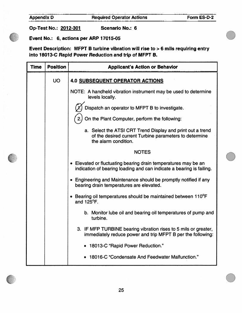
uo 4.0 SUBSEQUENT OPERATOR ACTIONS
NOTE: A handheld vibration instrument may be used to determinelevels locally.
Dispatch an operator to MFPT B to investigate.
On the Plant Computer, periorm the following:
a. Select the ATSI CRT Trend Display and print out a trendof the desired current Turbine parameters to determinethe alarm condition.
NOTES
. Elevated or fluctuating bearing drain temperatures may be anindication of bearing loading and can indicate a bearing is failing.
. Engineering and Maintenance should be promptly notified if anybearing drain temperatures are elevated.
. Bearing oil temperatures should be maintained between 110°Fand 125°F.
b. Monitor lube oil and bearing oil temperatures of pump andturbine.
3. IF MFP TURBINE bearing vibration rises to 5 mils or greater,immediately reduce power and trip MFPT B per the following:
• 18013-C “Rapid Power Reduction.”
• 18016-C “Condensate And Feedwater Malfunction.”
025

.
a
Appendix D Required Operator Actions Form ES-D-2
Op-Test No.: 2012-301 Scenario No.: 6
Event No.: 6, actions per ARP 1701 5-05
Event Description: MFPT B turbine vibration will rise to > 6 mils requiring entryinto 18013-C Rapid Power Reduction and trip of MFPT B.
Time Position ] Applicant’s Action or Behavior
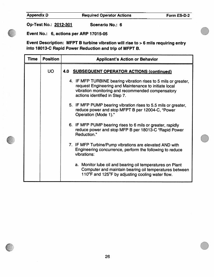
uo 4.0 SUBSEQUENT OPERATOR ACTIONS (continued)
4. IF MFP TURBINE bearing vibration rises to 5 mils or greater,request Engineering and Maintenance to initiate localvibration monitoring and recommended compensatoryactions identified in Step 7.
5. IF MFP PUMP bearing vibration rises to 5.5 mils or greater,reduce power and stop MFPT B per 1 2004-C, “PowerOperation (Mode 1).”
6. IF MFP PUMP bearing rises to 6 mils or greater, rapidlyreduce power and stop MFP B per 1 801 3-C “Rapid PowerReduction.”
7. IF MFP Turbine/Pump vibrations are elevated AND withEngineering concurrence, perform the following to reducevibrations:
a. Monitor lube oil and bearing oil temperatures on PlantComputer and maintain bearing oil temperatures between110°F and 125°F by adjusting cooling water flow.
026

Appendix D Required Operator Actions Form ES-D-2
Op-Test No.: 2012-301 Scenario No.: 6
Event No.: 6, actions per ARP 17015-05
Event Description: MFPT B turbine vibration will rise to > 6 mils requiring entryinto 18013-C Rapid Power Reduction and trip of MFPT B.
I Time Position Applicant’s Action or Behavior
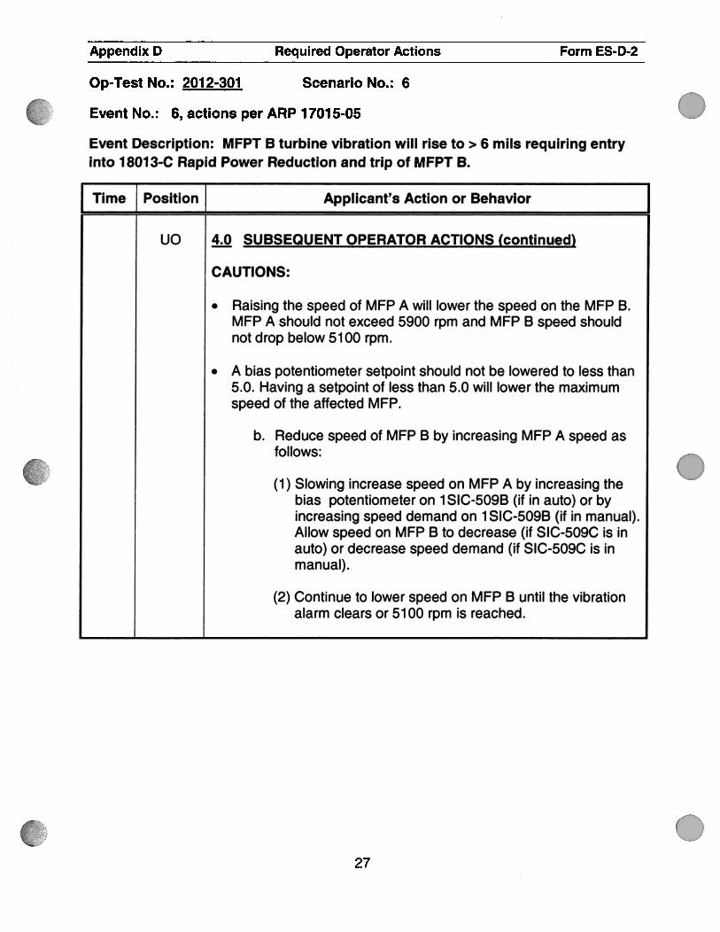
uc 4Q SUBSEQUENT OPERATOR ACTIONS (continued)
CAUTIONS:
. Raising the speed of MFP A will lower the speed on the MFP B.MFP A should not exceed 5900 rpm and MFP B speed shouldnot drop below 5100 rpm.
. A bias potentiometer setpoint should not be lowered to less than5.0. Having a setpoint of less than 5.0 will lower the maximumspeed of the affected MFP.
b. Reduce speed of MFP B by increasing MFP A speed asfollows:
(1 ) Slowing increase speed on MFP A by increasing thebias potentiometer on 1 SIC-509B (if in auto) or byincreasing speed demand on 1 SlC-509B (if in manual).Allow speed on MFP B to decrease (if SIC-509C is inauto) or decrease speed demand (if SIC-509C is inmanual).
(2) Continue to lower speed on MFP B until the vibrationalarm clears or 5100 rpm is reached.
.
.
27

Appendix D Required Operator Actions Form ES-D-2
Op-Test No.: 2012-301 Scenario No.: 6
Event No.: 6, actions per ARP 1701 5-05
Event Description: MFPT B turbine vibration will rise to > 6 mils requiring entryinto 18013-C Rapid Power Reduction and trip of MFPT B.
Time Position Applicant’s Action or Behavior
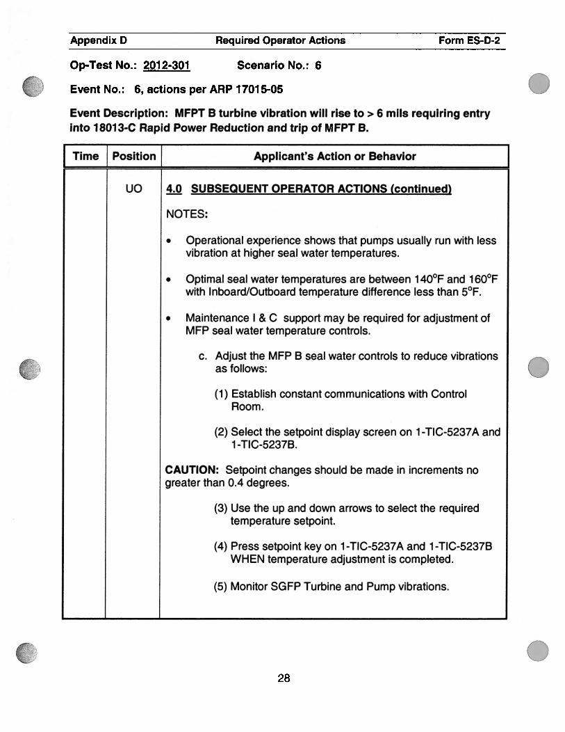
uo 4Q SUBSEQUENT OPERATOR ACTIONS (continued)
NOTES:
. Operational experience shows that pumps usually run with lessvibration at higher seal water temperatures.
. Optimal seal water temperatures are between 1 40°F and 160°Fwith Inboard/Outboard temperature difference less than 5°F.
. Maintenance I & C support may be required for adjustment ofMFP seal water temperature controls.
C. Adjust the MFP B seal water controls to reduce vibrationsas follows:
(1) Establish constant communications with ControlRoom.
(2) Select the setpoint display screen on 1 -TIC-5237A and1 -TIC-5237B.
CAUTION: Setpoint changes should be made in increments nogreater than 0.4 degrees.
(3) Use the up and down arrows to select the requiredtemperature setpoint.
(4) Press setpoint key on 1 -TIC-5237A and 1 -TIC-5237BWHEN temperature adjustment is completed.
(5) Monitor SGFP Turbine and Pump vibrations.
028

C
Appendix D Required Operator Actions Form ES-D-2
Op-Test No.: 2012-301 Scenario No.: 6
Event No.: 6, actions per ARP 1701 5-05
Event Description: MFPT B turbine vibration will rise to >6 mils requiring entryinto 18013-C Rapid Power Reduction and trip of MFPT B.
I Time Position Applicant’s Action or Behavior
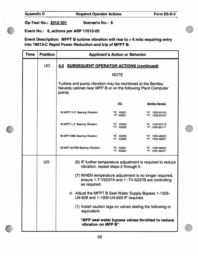
uc 4Q SUBSEQUENT OPERATOR ACTIONS (continued)
NOTE
Turbine and pump vibration may be monitored at the BentleyNevada cabinet near MFP B or on the following Plant Computerpoints.
E Bentley Nevada
lB MFPT H.P. Bearing Vibration: “X”. X0221 “X’. 1XIS-5310X“Y”. X0251 “Y”. 1XIS-5310Y
1 B MFPT L.P. Bearing Vibration: “X”. X0222 “X”. 1 XIS-531 1 X“Y”. X0252 “Y”. 1 XIS-531 1 Y
1 B MFP INBD Bearing Vibration: “X”. X0259 “X”. 1 XIS-4922X“Y,,. X0262 “Yfl. 1 XIS-4922Y
1 B MFP OUTBD Bearing Vibration: “X”. X0261 “X”. 1 XIS-4923X“Y,, X0262 “Y”. 1 XIS-4923Y
uO (6) IF further temperature adjustment is required to reducevibration, repeat steps 2 through 5.
(7) WHEN temperature adjustment is no longer required,ensure 1 -T-V5237A and 1 ‘ -TV-5237B are controllingas required.
d. Adjust the MFPT B Seal Water Supply Bypass 1 -1 305-U4-628 and 1 -1 305-U4-629 IF required.
(1) Install caution tags on valves stating the following orequivalent:
“MFP seal water bypass valves throttled to reducevibration on MFP B”
.
.
29

.
Appendix D Required Operator Actions Form ES-D-2
Op-Test No.: 2012-301 Scenario No.: 6
Event No.: 6, actions per ARP 1701 5-05
Event Description: MFPT B turbine vibration will rise to > 6 mils requiring entryinto 18013-C Rapid Power Reduction and trip of MFPT B.
Time Position Applicant’s Action or Behavior
UO 4M SUBSEQUENT OPERATOR ACTIONS (continued)
8. Scan ALB1 5 and ALB1 6 for associated alarms and takeappropriate actions.
.
0
.30


Appendix D Required Operator Actions Form ES-D-2
Op-Test No.: 2012-301 Scenario No.: 6
Event No.: 6
Event Description: MFPT B turbine vibration will rise to > 5 mils requiring entryinto 18013-C Rapid Power Reduction and trip of MFPT B.
I Time Position Applicant’s Action or Behavior
ss 18013-C, RAPID POWER REDUCTION actions.
Entry Condition Target Approx. Time @ 3-5% mm
17015-D05 MFPT High Vibrations <70% RTP 6 — 10 minutes17015-EO1
1 . Perform SHUTDOWN BRIEFING.
SSSHUTDOWN BRIEFING
METHOD
. Auto rod control should be used.
. Reduce Turbine Load at approximately 3% RTP per minute (approx 36 MWe) up to 5% RTP(approx 60 MWe).
. Borate AFD within the doghouse.
. ss (or SRO designee) — Maintain supervisory oversight.
. All rod withdrawals will be approved by the SS.
. Approval for each reactivity is not necessary as long as manipulations are made within theboundaries established in this briefing (i.e. turbine load adjustment up to 60 MWe, etc.
. A crew update should be performed at approximately every 1 00 MWe power change.
. If manpower is available, peer checks should be used for all reactivity changes.
OPERATiONAL LIMITS
. Maintain Tavg within ± 6°F of Tref. IF TAVG/TREF mismatch >6°F and not trending toward amatched condition or if Tavg 551°F, then trip the reactor.
. If load reduction due to a loss of vacuum, every effort should be made to maintain the steamdumps closed. (Permissive C-9 24.92” Hg).
INDUSTRY OE
. Shift supervision must maintain effective oversight and exercise conservative decision making.
. Correction of significant RCS Tavg deviations should only be via secondary plant controlmanipulations and not primary plant control manipulations (i.e. , do not withdraw control rods ordilute).
C .
.
.31
3cC
Oct (11 (Zo)
ai
pw&
Appendix D Required Operator Actions Form ES-D-2
Op-Test No.: 2012-301 Scenario No.: 6
Event No.: 6
Event Description: MFPT B turbine vibration will rise to> 5 mils requiring entryinto 18013-C Rapid Power Reduction and trip of MFPT B.
Time Position , Applicant’s Action or Behavior
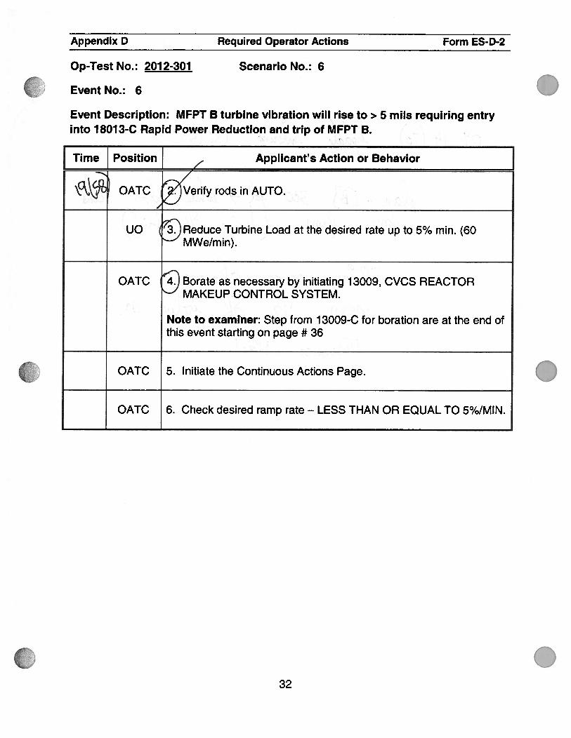
OATCd
rify rods in AUTO. . .
UO Reduce Turbine Load at the desired rate up to 5% mm. (60MWe/min).
OATC Borate as necessary by initiating 13009, CVCS REACTORMAKEUP CONTROL SYSTEM.
Note to examiner: Step from 13009-C for boration are at the end ofthis event starting on page # 36
OATC 5. Initiate the Continuous Actions Page.
OATC 6. Check desired ramp rate - LESS THAN OR EQUAL TO 5%/MIN.
.
032

6
.
.
Appendix D Required Operator Actions Form ES-D-2
Scenario No.: 6Op-Test No.: 2012-301
Event No.: 6
Event Description: MFPT B turbine vibration will rise to > 5 mils requiring entryinto 18013-C Rapid Power Reduction and trip of MFPT B.
Time Position } Applicant’s Action or Behavior
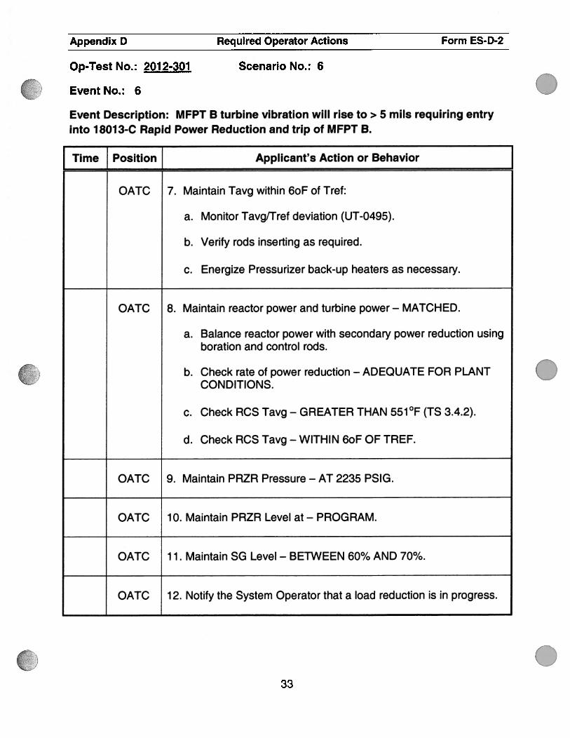
OATC 7. Maintain Tavg within 6oF of Tref:
a. Monitor TavglTref deviation (UT-0495).
b. Verify rods inserting as required.
C. Energize Pressurizer back-up heaters as necessary.
OATC 8. Maintain reactor power and turbine power — MATCHED.
a. Balance reactor power with secondary power reduction usingboration and control rods.
b. Check rate of power reduction — ADEQUATE FOR PLANTCONDITIONS.
C. Check RCS Tavg - GREATER THAN 551°F (TS 3.4.2).
d. Check RCS Tavg — WITHIN 6oF OF TREF.
OATC 9. Maintain PRZR Pressure — AT 2235 PSIG.
OATC 10. Maintain PRZR Level at - PROGRAM.
OATC 1 1 . Maintain SG Level — BETWEEN 60% AND 70%.
OATC 12. Notify the System Operator that a load reduction is in progress.
.
.
033

S
S
.
.
Appendix D Required Operator Actions Form ES-D-2
Op-Test No. : 201 2-301 Scenario No. : 6
Event No. : 6
Event Description: MFPT B turbine vibration will rise to > 5 mils requiring entryinto 1 801 3-C Rapid Power Reduction and trip of MFPT B.
I Time Position Applicant’s Action or Behavior
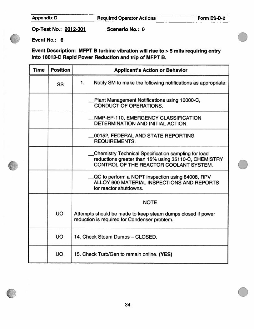
ss • Notify SM to make the following notifications as appropriate:
Management Notifications using 1 0000-c,CONDUCT OF OPERATIONS.
10, EMERGENCY CLASSIFICATIONDETERMINATION AND INITIAL ACTION.
FEDERAL AND STATE REPORTINGREQUI REMENTS.
Technical Specification sampling for loadreductions greater than 15% using 35110-C, CHEMISTRYCONTROL OF THE REACTOR COOLANT SYSTEM.
to perform a NOPT inspection using 84008, RPVALLOY 600 MATERIAL INSPECTIONS AND REPORTSfor reactor shutdowns.
NOTE
UO Attempts should be made to keep steam dumps closed if powerreduction is required for Condenser problem.
UO 14. Check Steam Dumps - CLOSED.
UO 15. Check Turb/Gen to remain online. (YES)
34

0
Appendix D Required Operator Actions Form ES-D-2
Scenario No.: 6Op-Test No.: 2012-301
Event No.: 6
Event Description: MFPT B turbine vibration will rise to> 5 mils requiring entryinto 18013-C Rapid Power Reduction and trip of MFPT B.
Time Position J Applicant’s Action or Behavior
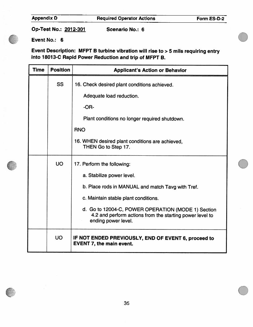
ss 1 6. Check desired plant conditions achieved.
Adequate load reduction.
-OR-
Plant conditions no longer required shutdown.
RNO
1 6. WHEN desired plant conditions are achieved,THEN Go to Step 17.
uO 17. Perform the following:
a. Stabilize power level.
b. Place rods in MANUAL and match Tavg with Tref.
c. Maintain stable plant conditions.
d. Go to 12004-C, POWER OPERATION (MODE 1) Section4.2 and perform actions from the starting power level toending power level.
UO IF NOT ENDED PREVIOUSLY, END OF EVENT 6, proceed toEVENT 7, the main event.
.
35

.
C .
.
0
Appendix D Required Operator Actions Form ES-D2
Op-Test No.: 2012-301 Scenario No.: 6
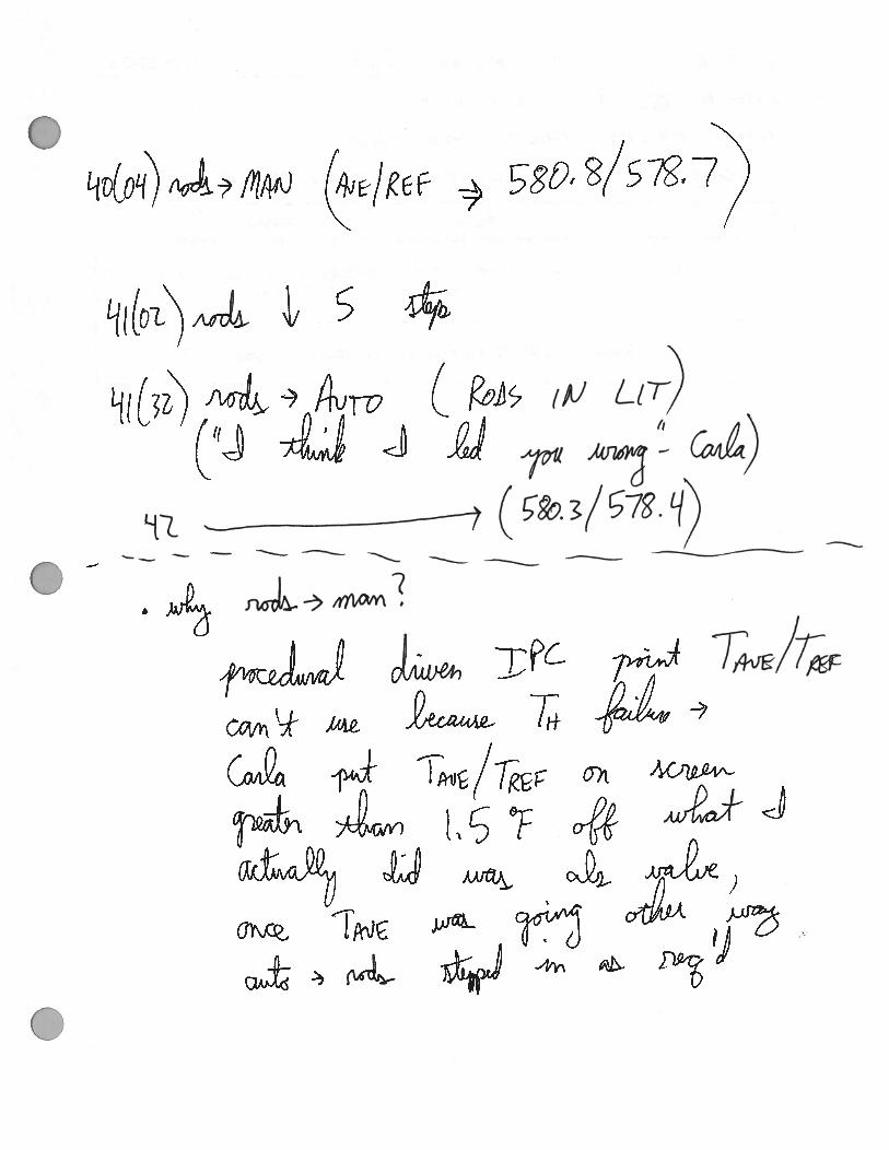
Event No. : 6 Rapid Power Reduction boration steps.
Event Description: Rapid Power Reduction boration steps from 13009.
Time Position Applicant’s Action or Behavior
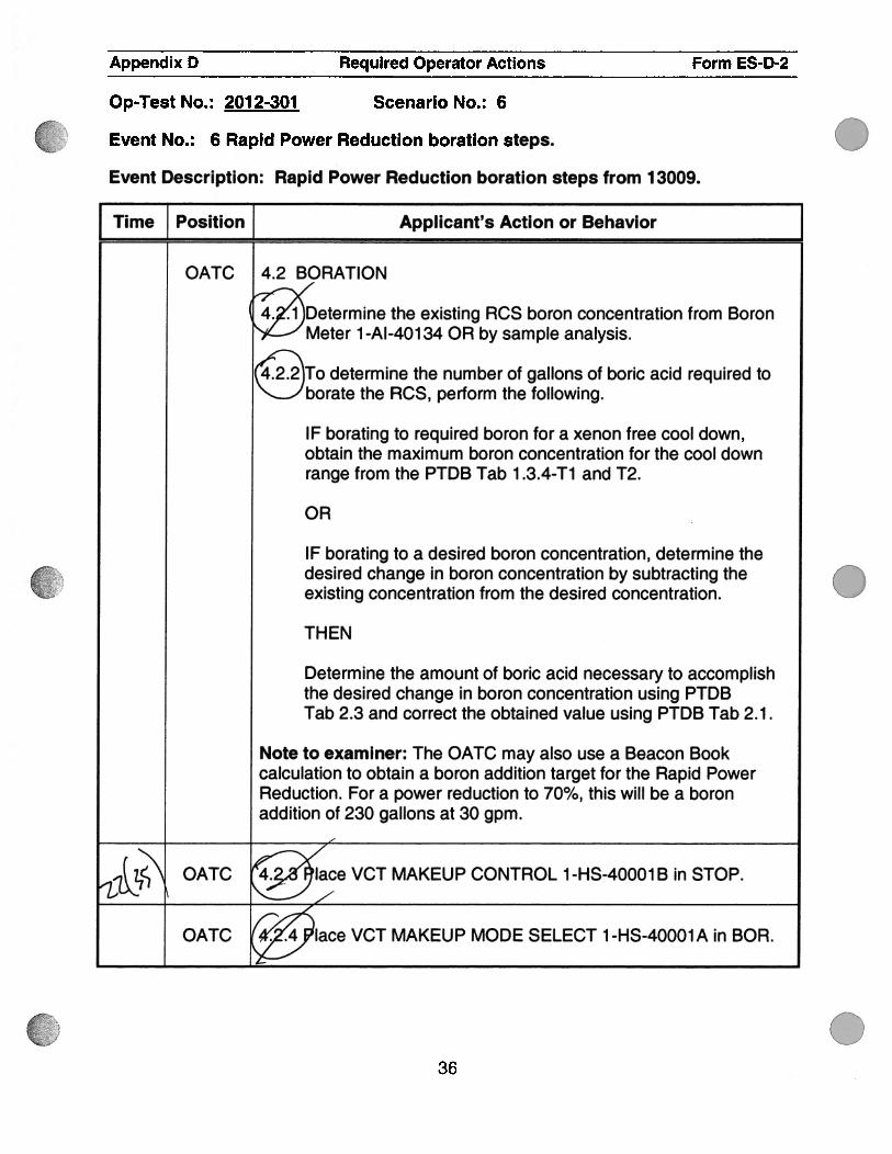
OATC 4.2 BORATION
4. . 1 Determine the existing RCS boron concentration from BoronMeter 1 -Al-401 34 OR by sample analysis.
4.2.2 To determine the number of gallons of boric acid required toborate the RCS, perform the following.
IF borating to required boron for a xenon free cool down,obtain the maximum boron concentration for the cool downrange from the PTDB Tab 1 .3.4-Ti and T2.
OR
IF borating to a desired boron concentration, determine thedesired change in boron concentration by subtracting theexisting concentration from the desired concentration.
THEN
Determine the amount of boric acid necessary to accomplishthe desired change in boron concentration using PTDBTab 2.3 and correct the obtained value using PTDB Tab 2.1.
Note to examiner: The OATC may also use a Beacon Bookcalculation to obtain a boron addition target for the Rapid PowerReduction. For a power reduction to 70%, this will be a boronaddition of 230 gallons at 30 gpm.
-lc%%;;’ OATC ace VCT MAKEUP CONTROL 1 -HS-40001 B in STOP.
OATC lace VCT MAKEUP MODE SELECT 1 -HS-40001 A in BOR.
36

.
.
Appendix D Required Operator Actions Form ES-D-2
Op-Test No. : 201 2-301 Scenario No. : 6
Event No. : 6 Rapid Power Reduction boration steps.
Event Description: Rapid Power Reduction boration steps from 13009.
I Time Position Applicant’s Action or Behavior
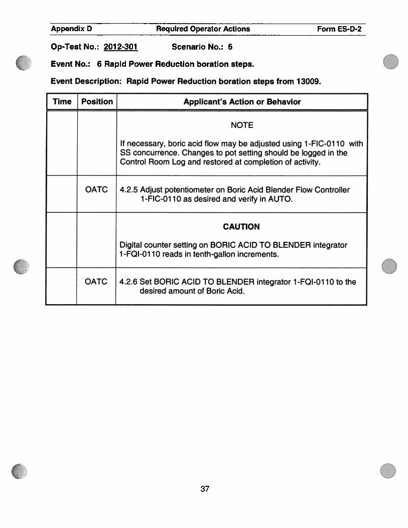
NOTE
If necessary, boric acid flow may be adjusted using 1 -FIC-O1 1 0 withss concurrence. Changes to pot seffing should be logged in theControl Room Log and restored at completion of activity.
OATC 4.2.5 Adjust potentiometer on Boric Acid Blender Flow Controller1 -FIC-Ol 10 as desired and verify in AUTO.
CAUTION
Digital counter setting on BORIC ACID TO BLENDER integrator1 -FQI-01 10 reads in tenth-gallon increments.
OATC 4.2.6 Set BORIC ACID TO BLENDER integrator 1 -FQI-01 10 to thedesired amount of Boric Acid.
37

I
(rd)I0
.
.
0
Appendix D Required Operator Actions Form ES-D-2
Op-Test No. : 201 2-301 Scenario No. : 6
Event No. : 6 Rapid Power Reduction boration steps.
Event Description: Rapid Power Reduction boration steps from 13009.
[ Time Position Applicant’s Action or Behavior
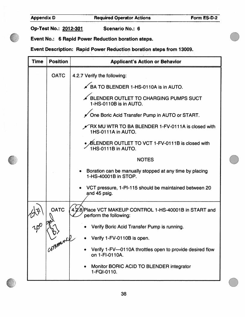
OATC 4.2.7 Verify the following:
/BA TO BLENDER 1 -HS-O1 1 OA is in AUTO.
/BLENDER OUTLET TO CHARGING PUMPS SUCT1 -HS-O1 1 OB is in AUTO.
,//One Boric Acid Transfer Pump in AUTO or START.
/RX MU WTR TO BA BLENDER 1 -FV-O1 1 1 A is closed with1HS-O111A in AUTO.
•%.ENDER OUTLET TO VCT 1 -FV-O1 1 1 B is closed withV 1HS-O111B in AUTO.
NOTES
. Boration can be manually stopped at any time by placing1-HS-40001B in STOP.
. VCT pressure, 1 -P1-i 15 should be maintained between 20and 45 p51g.
OATC Iace VCT MAKEUP CONTROL 1 -HS-40001 B in START and1 sL-’ perform the following:
‘L°.
Verify Boric Acid Transfer Pump is running.
_/ . Verify 1-FV-OlloBisopen.
64yV . Verify 1 -FV-—01 1 OA throttles open to provide desired flowon 1-Fl-O11OA.
• Monitor BORIC ACID TO BLENDER integrator1-FQI-01 10.
38

.
.
0
Appendix D Required Operator Actions Form ES-D-2
Op-Test No.: 2012-301 Scenario No.: 6
Event No. : 6 Rapid Power Reduction boration steps.
Event Description: Rapid Power Reduction boration steps from 13009.
I Time Position Applicant’s Action or Behavior
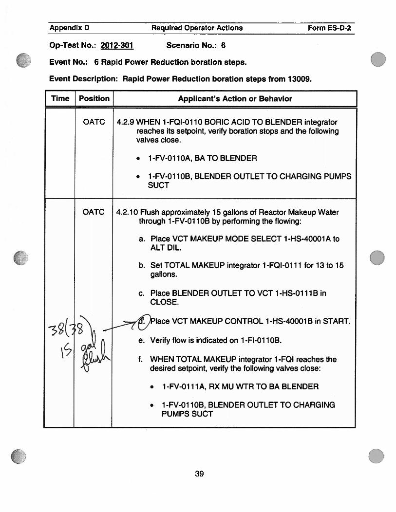
OATC 4.2.9 WHEN 1 -FQI-O1 1 0 BORIC ACID TO BLENDER integratorreaches its setpoint, verify boration stops and the followingvalves close.
. 1-FV-O11OA, BATO BLENDER
. 1-FV-O1 lOB, BLENDER OUTLET TO CHARGING PUMPSSUCT
OATC 4.2.10 Flush approximately 15 gallons of Reactor Makeup Waterthrough 1 -FV-O1 1 OB by performing the flowing:
a. Place VCT MAKEUP MODE SELECT 1-HS-40001A toALT DIL.
b. Set TOTAL MAKEUP integrator 1-FQI-O1 1 1 for 13 to 15gallons.
c. Place BLENDER OUTLET TO VCT 1 -HS-O1 1 1 B inCLOSE.
-3(:VCT MAKEUP CONTROL 1 -H540001 B in START.
e. Verify flow is indicated on 1 -Fl-O1 1 OB.‘o(yy,)Rr%% f. WHEN TOTAL MAKEUP integrator 1-FQI reaches theA desired setpoint, verify the following valves close:
• 1 -FV-O1 11 A, RX MU WTR TO BA BLENDER
. 1-FV-O1 lOB, BLENDER OUTLET TO CHARGINGPUMPS SUCT
39
çJ 0
0
.
T
vJ
L
\L/
VJ
03
cy(N cr
F1
c5
.
/
.
Appendix D Required Operator Actions Form ES-D-2
Op-Test No.: 2012-301 Scenario No.: 6
Event No. : 6 Rapid Power Reduction boration steps.
Event Description: Rapid Power Reduction boration steps from 13009.
Time Position Applicant’s Action or Behavior
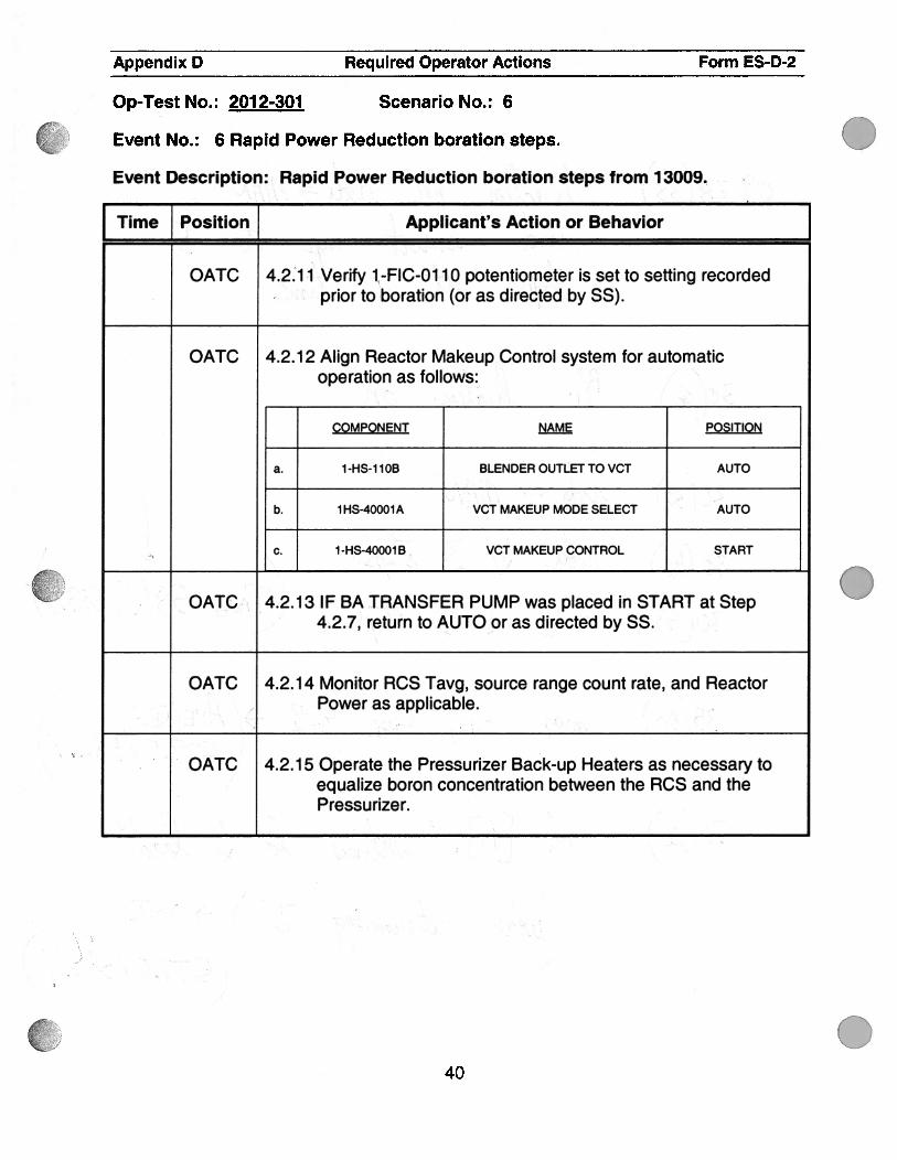
OATC 4.2:1 1 Verify 1 -FIC-Ol 1 0 potentiometer is set to setting recorded. prior to boration (or as directed by SS).
OATC 4.2.12 Align Reactor Makeup Control system for automaticoperation as follows:
COMPONENT NAME POSITION
a. 1 -HS-1 1 OB BLENDER OUTLET TO VCT AUTO
b. 1HS-40001A VCTMAKEUPMODESELECT AUTO
.‘.C. 1-HS-40001B VCT MAKEUP CONTROL START
. OATC 4.2.1 3 IF BA TRANSFER PUMP was placed in START at Step,
4.2.7, return to AUTO or as directed by 55.
OATC 4.2. 1 4 Monitor RCS Tavg, source range count rate, and ReactorPower as applicable. .
. OATC 4.2.15 Operate the Pressurizer Back-up Heaters as necessary toequalize boron concentration between the RCS and the
. Pressurizer.
40
(1
00
H
1
2I
.Appendix D Required Operator Actions Form ES-D-2
Op-Test No.: 201 2-301 Scenario No.: 6
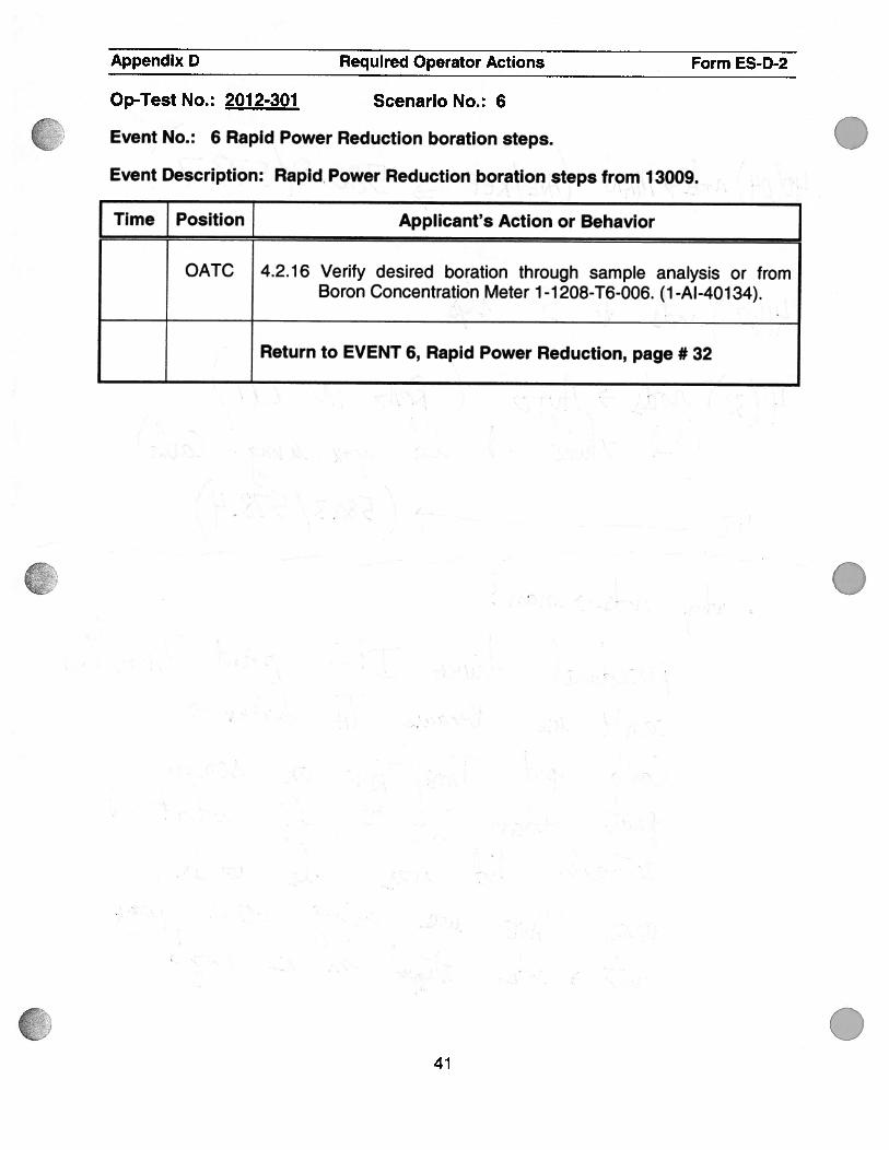
Event No.: 6 Rapid Power Reduction boration steps.
Event Description: Rapid Power Reduction boration steps from 13009.
f Time Position Applicant’s Action or Behavior
OATC 4.2.16 Verify desired boration through sample analysis or fromBoron Concentration Meter 1-1 208-T6-006. (1 -Al-401 34).
Return to EVENT 6, Rapid Power Reduction, page #32
41
.
.

Appendix D Required Operator Actions Form ES-D-2
Op-Test No.: 2012-301 Scenario No.: 3
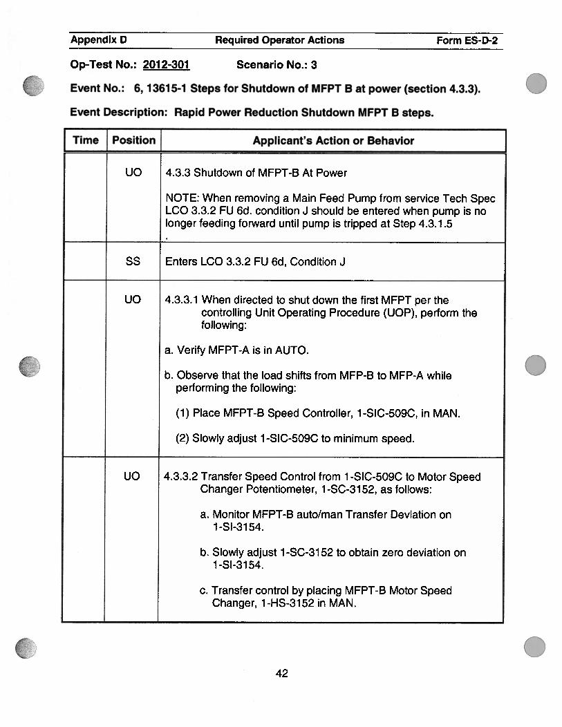
Event No.: 6, 13615-1 Steps for Shutdown of MFPT B at power (section 4.3.3).
Event Description: Rapid Power Reduction Shutdown MFPT B steps.
.
Q
0
I Time Position Applicant’s Action or Behavior Juo 4.3.3 Shutdown of MFPT-B At Power
NOTE: When removing a Main Feed Pump from service Tech SpecLCO 3.3.2 FU 6d. condition J should be entered when pump is nolonger feeding forward until pump is tripped at Step 4.3.1.5
SS Enters LCO 3.3.2 FU 6d, Condition J
uO 4.3.3.1 When directed to shut down the first MFPT per thecontrolling Unit Operating Procedure (UOP), perform thefollowing:
a. Verify MFPT-A is in AUTO.
b. Observe that the load shifts from MFP-B to MFP-A whileperforming the following:
(1 ) Place MFPT-B Speed Controller, 1 -SIC-509C, in MAN.
(2) Slowly adjust 1 -SIC-509C to minimum speed.
UO 4.3.3.2 Transfer Speed Control from 1 -SIC-509C to Motor SpeedChanger Potentiometer, 1 -SC-31 52, as follows:
a. Monitor MFPT-B auto/man Transfer Deviation on1 -Sl-31 54.
b. Slowly adjust 1-SC-3152 to obtain zero deviation on1 -Sl-31 54.
c. Transfer control by placing MFPT-B Motor SpeedChanger, 1-HS-3152 in MAN.
42

.
.
0
0
Appendix D Required Operator Actions Form ES-D-2
Op-Test No. : 201 2-301 Scenario No. : 3
Event No.: 6, 13615-1 Steps for Shutdown of MFPT B at power (section 4.3.3).
Event Description: Rapid Power Reduction Shutdown MFPT B steps.
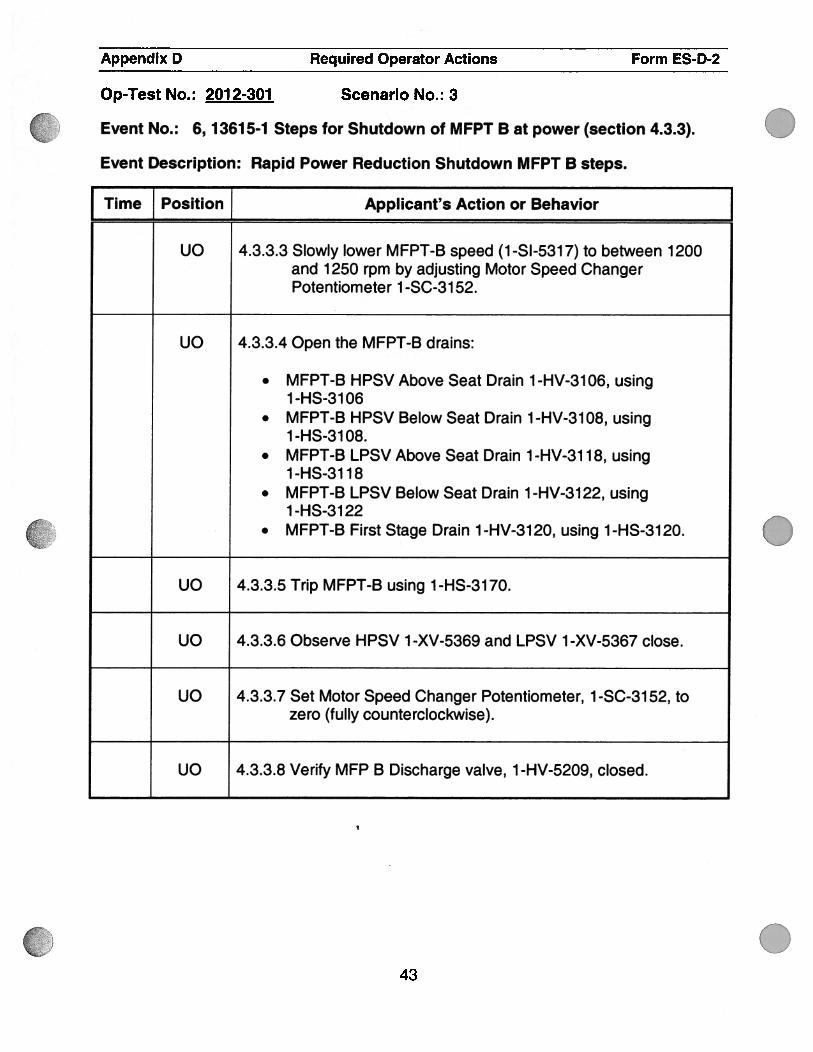
Time Position J Applicant’s Action or Behavior
uo 4.3.3.3 Slowly lower MFPT-B speed (1-Sl-5317) to between 1200and 1250 rpm by adjusting Motor Speed ChangerPotentiometer 1 -SC-31 52.
uo 4.3.3.4 Open the MFPT-B drains:
. MFPT-B HPSV Above Seat Drain 1-HV-3106, using1 -HS-31 06
. MFPT-B HPSV Below Seat Drain 1 -HV-31 08, using1 -HS-31 08.
. MFPT-B LPSV Above Seat Drain 1 -HV-31 1 8, using1-HS-31 18
. MFPT-B LPSV Below Seat Drain 1-HV-3122, using1 -HS-31 22
. MFPT-B First Stage Drain 1 -HV-31 20, using 1 -HS-31 20.
uO 4.3.3.5 Trip MFPT-B using 1-HS-3170.
UO 4.3.3.6 Observe HPSV 1 -XV-5369 and LPSV 1 -XV-5367 close.
UO 4.3.3.7 Set Motor Speed Changer Potentiometer, 1-SC-3152, tozero (fully counterclockwise).
UO 4.3.3.8 Verify MFP B Discharge valve, 1 -HV-5209, closed.
43

Appendix D Required Operator Actions Form ES-D-2
Op-Test No.: 2012-301 Scenario No.: 3
Event No.: 6, 13615-1 Steps for Shutdown of MFPT B at power (section 4.3.3).
Event Description: Rapid Power Reduction Shutdown MFPT B steps.
.
.
Time Position Applicant’s Action or Behavior
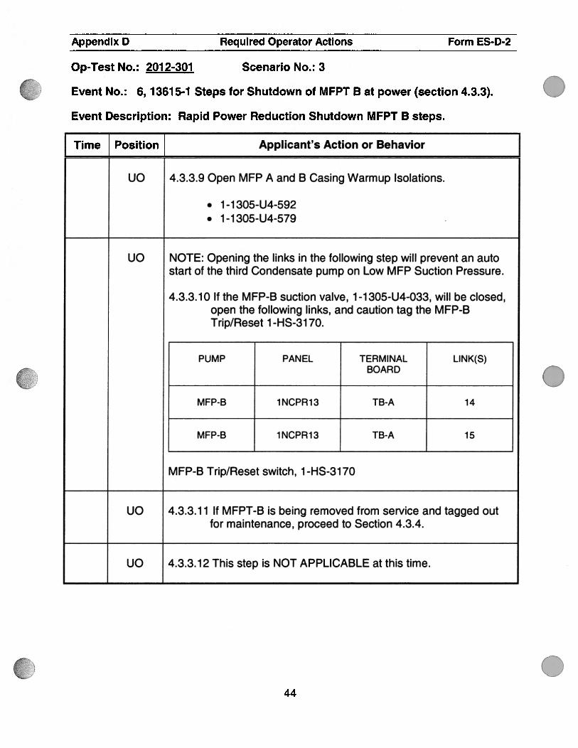
uo 4.3.3.9 Open MFP A and B Casing Warmup Isolations.
. 1-1305-U4-592
. 1 -1 305-U4-579
uO NOTE: Opening the links in the following step will prevent an autostart of the third Condensate pump on Low MFP Suction Pressure.
4.3.3.10 If the MFP-B suction valve, 1-1305-U4-033, will be closed,open the following links, and caution tag the MFP-BTrip/Reset 1 -HS-31 70.
PUMP PANEL TERMINAL LINK(S)BOARD
MFP-B 1NCPR13 TB-A 14
MFP-B 1NCPR13 TB-A 15
MFP-B Trip/Reset switch, 1-HS-3170
uO 4.3.3.11 If MFPT-B is being removed from service and tagged outfor maintenance, proceed to Section 4.3.4.
uO 4.3.3.12 This step is NOT APPLICABLE at this time.
44

S
Appendix D Required Operator Actions Form ES-D-2
Op-Test No.: 2012-301 Scenario No.: 6
Event No.: 7
Event Description: ATWT with failure of auto rod motion, Turbine auto trip, autostart of all AFW pumps, and faulted Steam Generator(s) as Safeties lift and fail toreseat when the Turbine trips.
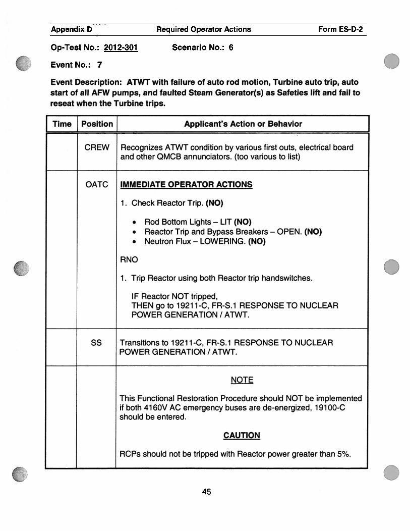
Time f Position ] Applicant’s Action or Behavior JCREW Recognizes ATWT condition by various first outs, electrical board
and other QMCB annunciators. (too various to list)
QATC IMMEDIATE OPERATOR ACTIONS
1 . Check Reactor Trip. (NO)
. Rod Bottom Lights — LIT (NO)
. Reactor Trip and Bypass Breakers — OPEN. (NO)
. Neutron Flux — LOWERING. (NO)
RNO
1 . Trip Reactor using both Reactor trip handswitches.
IF Reactor NOT tripped,THEN go to 1921 1-C, FR-S.1 RESPONSE TO NUCLEARPOWER GENERATION I ATWT.
55 Transitions to 1921 1-C, FR-S.1 RESPONSE TO NUCLEARPOWER GENERATION I ATWT.
NOTE
This Functional Restoration Procedure should NOT be implementedif both 4160V AC emergency buses are de-energized, 19100-Cshould be entered.
CAUTION
RCPs should not be tripped with Reactor power greater than 5%.
( .
.
045

Lo)L1LQ1
61
Appendix D Required Operator Actions Form ES-D-2
Op-Test No.: 2012-301
Event No.: 7
Scenario No.: 6
Event Description: ATWT with failure of auto rod motion, Turbine auto trip, autostart of all AFW pumps, and faulted Steam Generator(s) as Safeties lift and fail toreseat when the Turbine trips.
.
.
Time Position J Applicant’s Action or Behavior
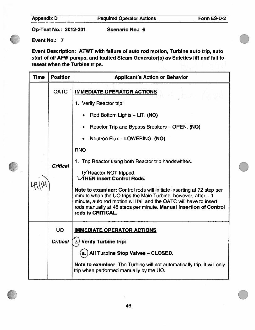
OATC IMMEDIATE OPERATOR ACTIONS . ,
1 . Verify Reactor trip:
. Rod Bottom Lights — LIT. (NO)
. Reactor Trip and Bypass Breakers — OPEN. (NO)
. Neutron Flux — LOWERING. (NO)
RNO
1 . Trip Reactor using both Reactor trip handswithes.Critical
IReactor NOT tripped,\AHEN insert Control Rods.
LtkNote to examiner: Control rods will initiate inserting at 72 step perminute when the UO trips the Main Turbine, however, after 1minute, auto rod motion will fail and the OATC will have to insertrods manually at 48 steps per minute. Manual insertion of Controlrods is CRITICAL.
uO IMMEDIATE OPERATOR ACTIONS
Critical : Verify Turbine trip:
All Turbine Stop Valves — CLOSED.
Note to examiner: The Turbine will not automatically trip, it will onlytrip when performed manually by the UO.
46

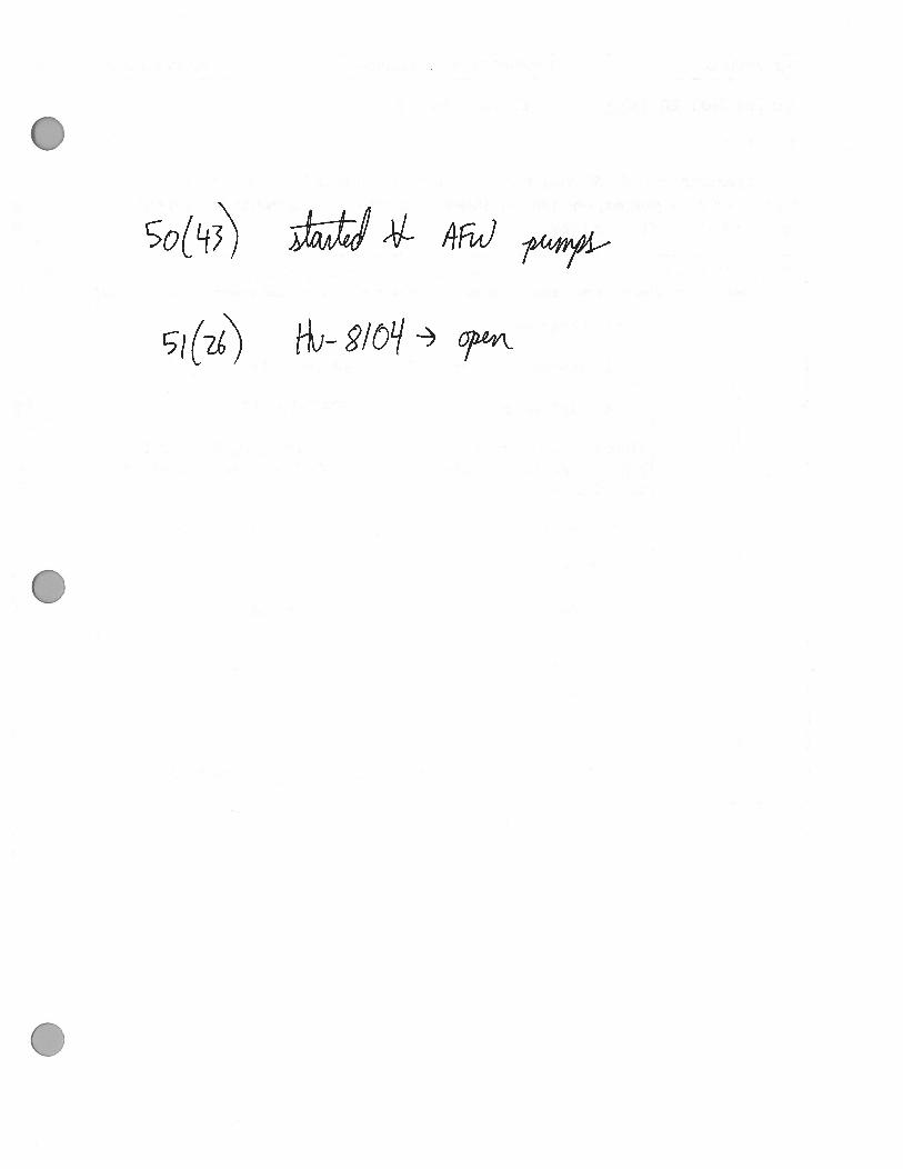
.
Appendix D Required Operator Actions Form ES-D-2
Scenario No.: 6OpTest No.: 2012-301
Event No.: 7
Event Description: ATWT with failure of auto rod motion, Turbine auto trip, autostart of all AFW pumps, and faulted Steam Generator(s) as Safeties lift and fail toreseat when the Turbine trips.
I Time Position Applicant’s Action or Behavior
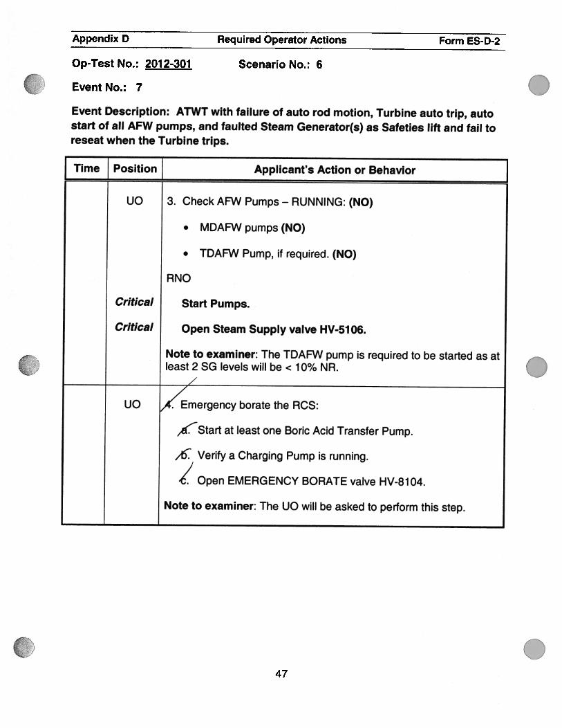
Uo 3. Check AFW Pumps - RUNNING: (NO)
. MDAFWpumps(NO)
. TDAFW Pump, if required. (NO)
RNO
Critical Start Pumps.
Critical Open Steam Supply valve HV-51 06.
Note to examiner: The TDAFW pump is required to be started as atleast 2 SG levels will be < 1 0% NR.
UO mergency borate the RCS:
,Start at least one Boric Acid Transfer Pump.
,t5 Verify a Charging Pump is running.
Open EMERGENCY BORATE valve HV-8104.
Note to examiner: The UO will be asked to perform this step.
.
.
.47
Appendix D Required Operator Actions Form ES-D-2
Op-Test No.: 201 2-301 Scenario No.: 6
Event No.: 7
Event Description: ATWT with failure of auto rod motion, Turbine auto trip, autostart of all AFW pumps, and faulted Steam Generator(s) as Safeties lift and fail toreseat when the Turbine trips.
Time Position J Applicant’s Action or Behavior
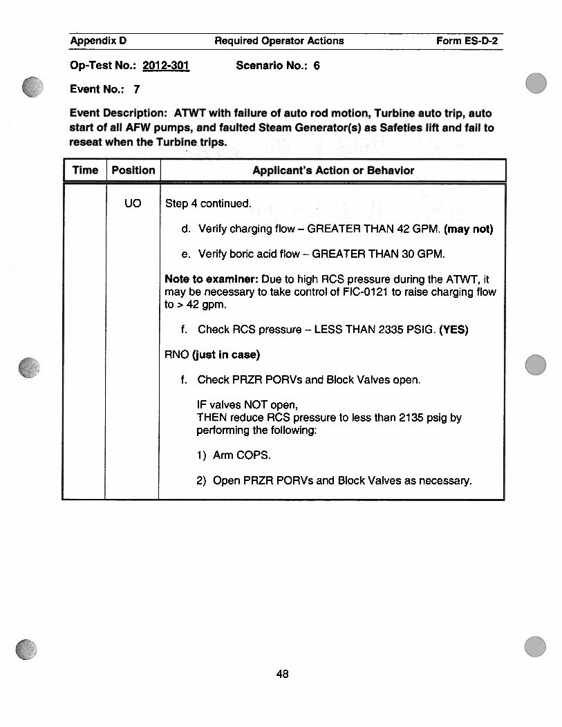
uo Step 4 continued.
d. Verify charging flow — GREATER THAN 42 GPM. (may not)
e. Verify boric acid flow — GREATER THAN 30 GPM.
Note to examiner: Due to high RCS pressure during the ATWT, itmay be necessary to take control of FIC-0121 to raise charging flowto > 42 gpm.
f. Check RCS pressure — LESS THAN 2335 P51G. (YES)
RNO (just in case)
f. Check PRZR PORVs and Block Valves open.
IF valves NOT open,THEN reduce RCS pressure to less than 2135 psig byperforming the following:
1) Arm COPS.
2) Open PRZR PORVs and Block Valves as necessary.
.
.
.48

• •.&• .‘
• .:•
/1
Appendix D Required Operator Actions Form ES-D-2
Op-Test No.: 2012-301 Scenario No.: 6
Event No.: 7
Event Description: ATWT with failure of auto rod motion, Turbine auto trip, autostart of all AFW pumps, and faulted Steam Generator(s) as Safeties lift and fail toreseat when the Turbine trips.
Time Position Applicant’s Action or Behavior
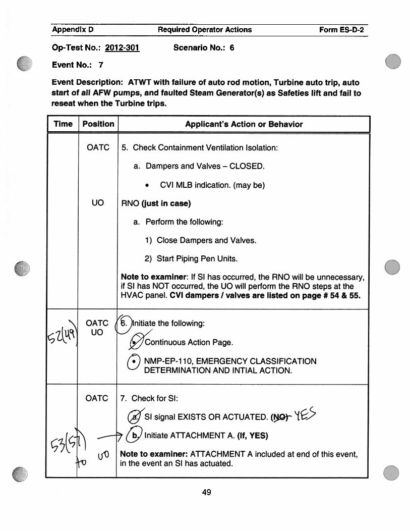
OATC 5. Check Containment Ventilation Isolation:
a. Dampers and Valves — CLOSED.
. CVI MLB indication. (may be)
uO RNO (just in case)
a. Perform the following:
1 ) Close Dampers and Valves.
2) Start Piping Pen Units.
Note to examiner: If SI has occurred, the RNO will be unnecessary,if SI has NOT occurred, the UO will perform the RNO steps at theHVAC panel. CVI dampers I valves are listed on page # 54 & 55.
OATC ‘ . Initiate the following:fkc UO‘2 \. j9Continuous Action Page.
NMP-EP-1 10, EMERGENCY CLASSIFICATIONDETERMI NATION AND I NTIAL ACTION.
OATC 7. CheckforSl:/
SI signal EXISTS OR ACTUATED. (J.O)
t;‘(5 7 & Initiate ATTACHMENT A. (If, YES)
Note to examiner: ATTACHMENT A included at end of this event,V in the event an SI has actuated.
.
49

.
Appendix D Required Operator Actions Form ES-D-2
Op-Test No.: 2012-301
Event No.: 7
Scenario No.: 6
Event Description: ATWT with failure of auto rod motion, Turbine auto trip, autostart of all AFW pumps, and faulted Steam Generator(s) as Safeties lift and fail toreseat when the Turbine trips.
.
0
.
I TimeJ_Position
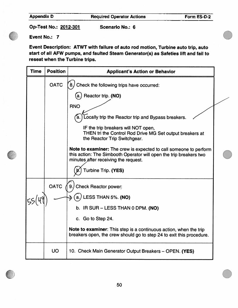
Applicant’s Action or Behavior
OATC Check the following trips have occurred:
Reactor trip. (NO)
RNO
D Locally trip the Reactor trip and Bypass breakers.
IF the trip breakers will NOT open,THEN tn the Control Rod Drive MG Set output breakers atthe Reactor Trip Switchgear.
Note to examiner: The crew is expected to call someone to performthis action: The Simbooth Operator will open the trip breakers twominute,after receiving the request.
. Turbine Trip. (YES)
OATC Check Reactor power
ç,%(L{ ) ..-----
% LESS THAN 5%. (NO)
b. IR SUR - LESS THAN 0 DPM. (NO)
c. Go to Step 24.
Note to examiner: This step is a continuous action, when the tripbreakers open, the crew should go to step 24 to exit this procedure.
UO 10. Check Main Generator Output Breakers — OPEN. (YES)
50

Appendix D Required Operator Actions Form ES-D-2
Scenario No.: 6Op-Test No.: 2012-301
Event No.: 7
Event Description: ATWT with failure of auto rod motion, Turbine auto trip, autostart of all AFW pumps, and faulted Steam Generator(s) as Safeties lift and fail toreseat when the Turbine trips.
Time Position Applicant’s Action or Behavior
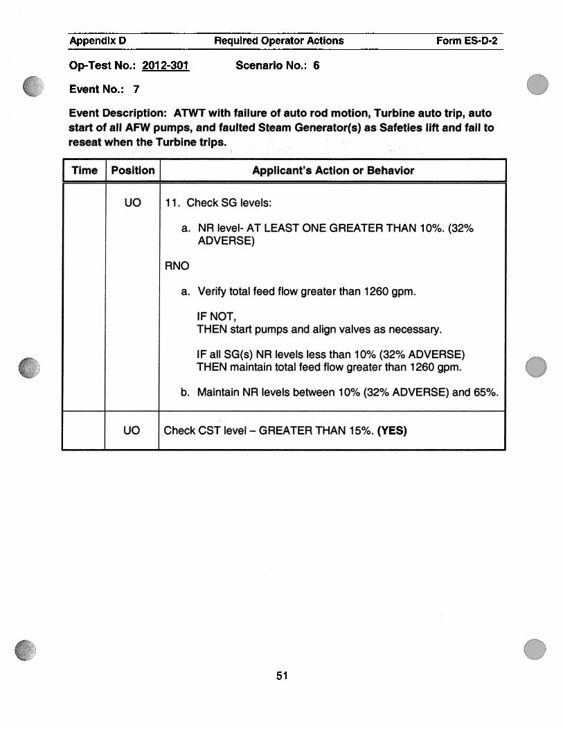
uo 1 1 . Check SG levels:
a. NR level- AT LEAST ONE GREATER THAN 10%. (32%ADVERSE)
RNO
a. Verify total feed flow greater than 1260 gpm.
IF NOT,THEN start pumps and align valves as necessary.
IF all SG(s) NR levels less than 10% (32% ADVERSE)THEN maintain total feed flow greater than 1260 gpm.
b. Maintain NR levels between 10% (32% ADVERSE) and 65%.
UO Check CST level - GREATER THAN 15%. (YES)
.
.
51

c7(o7) fl6e
Appendix D Required Operator Actions Form ES-D-2
Op-Test No.: 2012-301 Scenario No.: 6
Event No.: 7
Event Description: ATWT with failure of auto rod motion, Turbine auto trip, autostart of all AFW pumps, and faulted Steam Generator(s) as Safeties lift and fail toreseat when the Turbine trips.
Time_ Position j Applicant’s Action or Behavior
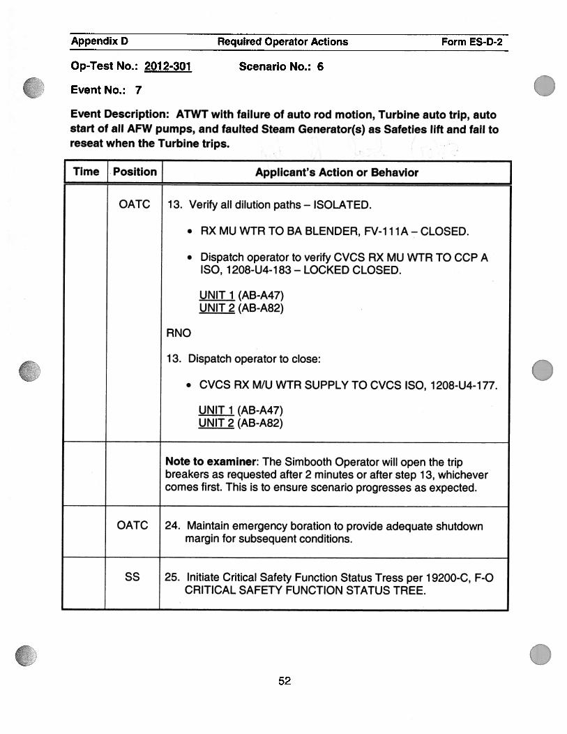
OATC 1 3. Verify all dilution paths — ISOLATED.
. RX MU WTR TO BA BLENDER, FV-1 hA-CLOSED.
. Dispatch operator to verify CVCS RX MU WTR TO CCP AISO, 1208-U4-h83 - LOCKED CLOSED.
UNIT 1 (AB-A47)UNIT 2 (AB-A82)
RNO
h 3. Dispatch operator to close:
. CVCS RX M/U WTR SUPPLY TO CVCS ISO, 1208-U4-h77.
UNIT 1 (AB-A47)UNIT 2 (AB-A82)
Note to examiner: The Simbooth Operator will open the tripbreakers as requested after 2 minutes or after step 13, whichevercomes first. This is to ensure scenario progresses as expected.
OATC 24. Maintain emergency boration to provide adequate shutdownmargin for subsequent conditions.
SS 25. Initiate Critical Safety Function Status Tress per h 9200-C, F-OCRITICAL SAFETY FUNCTION STATUS TREE.
52

Appendix D Required Operator Actions Form ES-D-2
Op-Test No.: 2012-301 Scenario No.: 6
Event No.: 7
Event Description: ATWT with failure of auto rod motion, Turbine auto trip, autostart of all AFW pumps, and faulted Steam Generator(s) as Safeties lift and fail toreseat when the Turbine trips.
Time Position Applicant’s Action or Behavior JSS 26. Return to procedure and step in effect.
Note to examiner: The actions for E-O are on the following pages.
0
53

Appendix D Required Operator Actions Form ES-D-2
Scenario No.: 6Op-Test No.: 2012-301
Event No.: 7
Event Description: ATWT with failure of auto rod motion, Turbine auto trip, autostart of all AFW pumps, and faulted Steam Generator(s) as Safeties lift and fail toreseat when the Turbine trips.
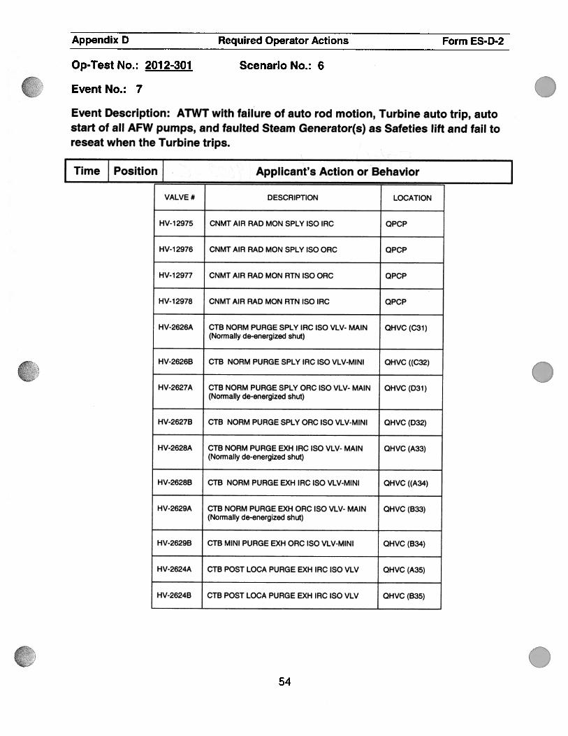
HV-12975 CNMT AIR RAD MON SPLY ISO IRC QPCP
HV-12976 CNMT AIR RAD MON SPLY ISO ORC QPCP
HV-12977 CNMT AIR RAD MON RTN ISO ORG QPCP
HV-12978 CNMT AIR RAD MON RTN ISO IRC QPCP
HV-2626A CTB NORM PURGE SPLY IRC ISO VLV- MAIN QHVC (C31)(Normally de-energized shut)
HV-2626B CTB NORM PURGE SPLY IRC ISO VLV-MINI QHVC ((C32)
HV-2627A CTB NORM PURGE SPLY ORC ISO VLV- MAIN QHVC (D31)(Normally de-energized shut)
HV-2627B CTB NORM PURGE SPLY ORC ISO VLV-MINI QHVC (D32)
HV-2628A CTB NORM PURGE EXH IRC ISO VLV- MAIN QHVC (A33)(Normally de-energized shut)
HV-2628B CTB NORM PURGE EXH IRC ISO VLV-MINI QHVC ((A34)
HV-2629A CTB NORM PURGE EXH ORC ISO VLV- MAIN QHVC (B33)(Normally de-energized shut)
HV-2629B CTB MINI PURGE EXH ORG ISO VLV-MINI QHVC (B34)
HV-2624A CTB POST LOCA PURGE EXH IRC ISO VLV QHVC (A35)
HV-2624B CTB POST LOCA PURGE EXH IRC ISO VLV QHVC (835)
Time Position Applicant’s Action or ‘Behavior
VALVE # DESCRIPTION LOCATION
.
0
.54

.
0
Appendix D Required Operator Actions Form ES-D-2
Scenario No.: 6Op-Test No.: 2012-301
Event No.: 7
Event Description: ATWT with failure of auto rod motion, Turbine auto trip, autostart of all AFW pumps, and faulted Steam Generator(s) as Safeties lift and fail toreseat when the Turbine trips.
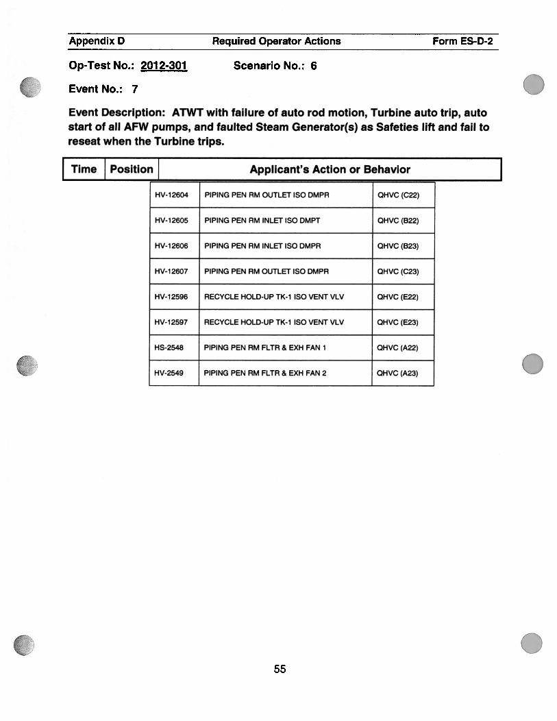
HV-12605 PIPING PEN RM INLET ISO DMPT QHVC (B22)
HV-12606 PIPING PEN RM INLET ISO DMPR QHVC (B23)
HV-12607 PIPING PEN RM OUTLET ISO DMPR QHVC (C23)
HV-12596 RECYCLE HOLD-UP TK-1 ISO VENT VLV QHVC (E22)
HV-12597 RECYCLE HOLD-UP TK-1 ISO VENT VLV QHVC (E23)
HS-2548 PIPING PEN RM FLTR & EXH FAN 1 QHVC (A22)
HV-2549 PIPING PEN RM FLTR & EXH FAN 2 QHVC (A23)
Time Position Applicant’s Action or Behavior
HV-12604 PIPING PEN RM OUTLET ISO DMPR QHVC (C22)
.
0
055

Appendix D Required Operator Actions Form ESD-2
Op-Test No.: 2012-301 Scenario No.: 6
Event No.: 7 Faulted SG (Code Safety Open on SG #4)
Event Description: During the ATWT, SG Safeties will lift on all SG(s), however,safety valve Loop # 4 will fail to reseat. These are the actions for E-0.
Time Position Applicant’s Action or Behavior
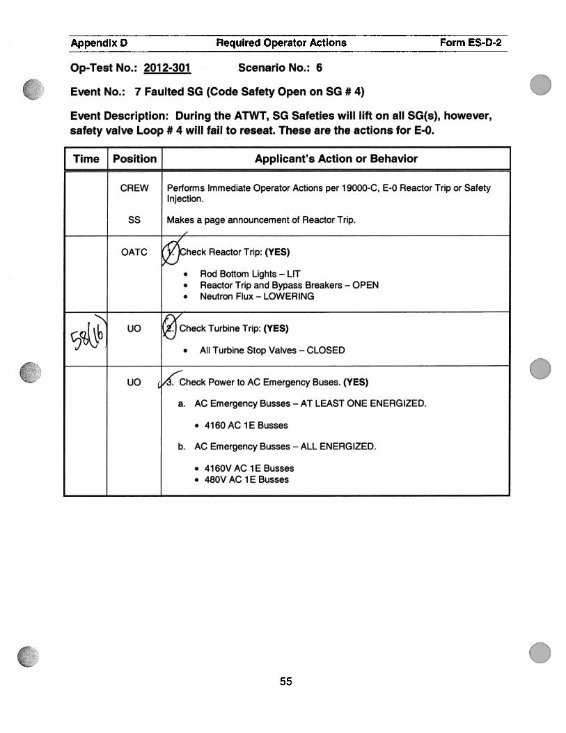
CREW Performs Immediate Operator Actions per 1 9000-C, E-0 Reactor Trip or SafetyInjection.
SS Makes a page announcement of Reactor Trip.
OATC heck Reactor Trip: (YES)
. Rod Bottom Lights — LIT
. Reactor Trip and Bypass Breakers — OPEN
. Neutron Flux — LOWERING
E??1& ‘heck Turbine Trip: (YES)
• All Turbine Stop Valves — CLOSED
UO (heck Power to AC Emergency Buses. (YES)
a. AC Emergency Busses — AT LEAST ONE ENERGIZED.
• 4l6OAClEBusses
b. AC Emergency Busses — ALL ENERGIZED.
• 4l6OVAClEBusses• 480V AC 1 E Busses
055

Appendix D Required Operator Actions Form ES-D-2
Op-Test No.: 2012-301 Scenario No.: 6
Event No.: 7 Faulted SG (Code Safety Open on SG #4)
Event Description: During the ATWT, SG Safeties will lift on all SG(s), however,safety valve Loop # 4 will fail to reseat. These are the actions for E-0.
Time Position f Applicant’s Action or Behavior
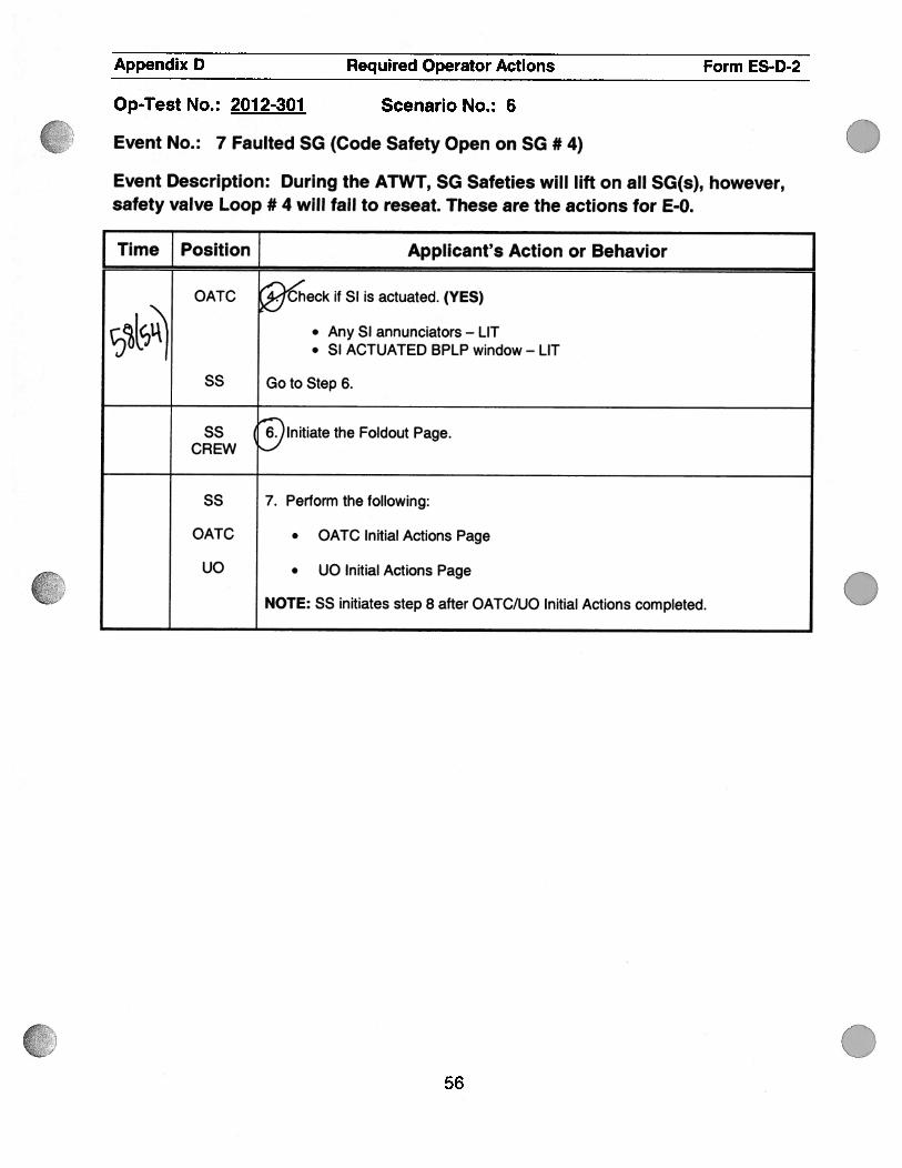
OATC ‘6ieck if SI is actuated. (YES)
• AnySi annunciators—LITVJ
• SI ACTUATED BPLP window — LIT
SS Goto Step 6.
SS )lnitiate the Foldout Page.CREW —‘
SS 7. Perform the following:
OATC • OATC Initial Actions Page
UO • UO Initial Actions Page
NOTE: SS initiates step 8 after OATC/UO Initial Actions completed. .
056
.
I
.
Appendix D Required Operator Actions Form ES-D-2
Op-Test No.: 2012-301 Scenario No.: 6
Event No.: 7 Faulted SG (Code Safety Open on SG #4)
Event Description: During the ATWT, SG Safeties will lift on all SG(s), however,safety valve Loop # 4 will fail to reseat. These are the actions for E-0.
I Time Position Applicant’s Action or Behavior
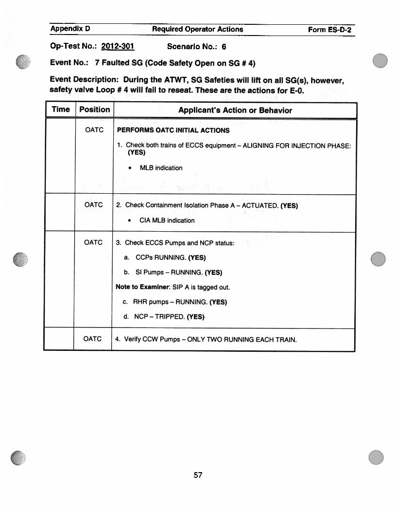
OATC PERFORMS OATC INITIAL ACTIONS
1 . Check both trains of ECCS equipment — ALIGNING FOR INJECTION PHASE:(YES)
. MLB indication
OATC 2. Check Containment Isolation Phase A — ACTUATED. (YES)
• CIA MLB indication
OATC 3. Check ECCS Pumps and NCP status:
a. CCPs RUNNING. (YES)
b. Si Pumps - RUNNING. (YES)
Note to Examiner: SIP A is tagged out.
c. RHR pumps - RUNNING. (YES)
d. NCP — TRIPPED. (YES)
OATC 4. Verify CCW Pumps - ONLY TWO RUNNING EACH TRAIN.
.
57

..
.
Appendix D Required Operator Actions Form ES-D-2
Op-Test No.: 2012-301 Scenario No.: 6
Event No.: 7 Faulted SG (Code Safety Open on SG #4)
Event Description: During the ATWT, SG Safeties will lift on all SG(s), however,safety valve Loop # 4 will fail to reseat. These are the actions for E-0.
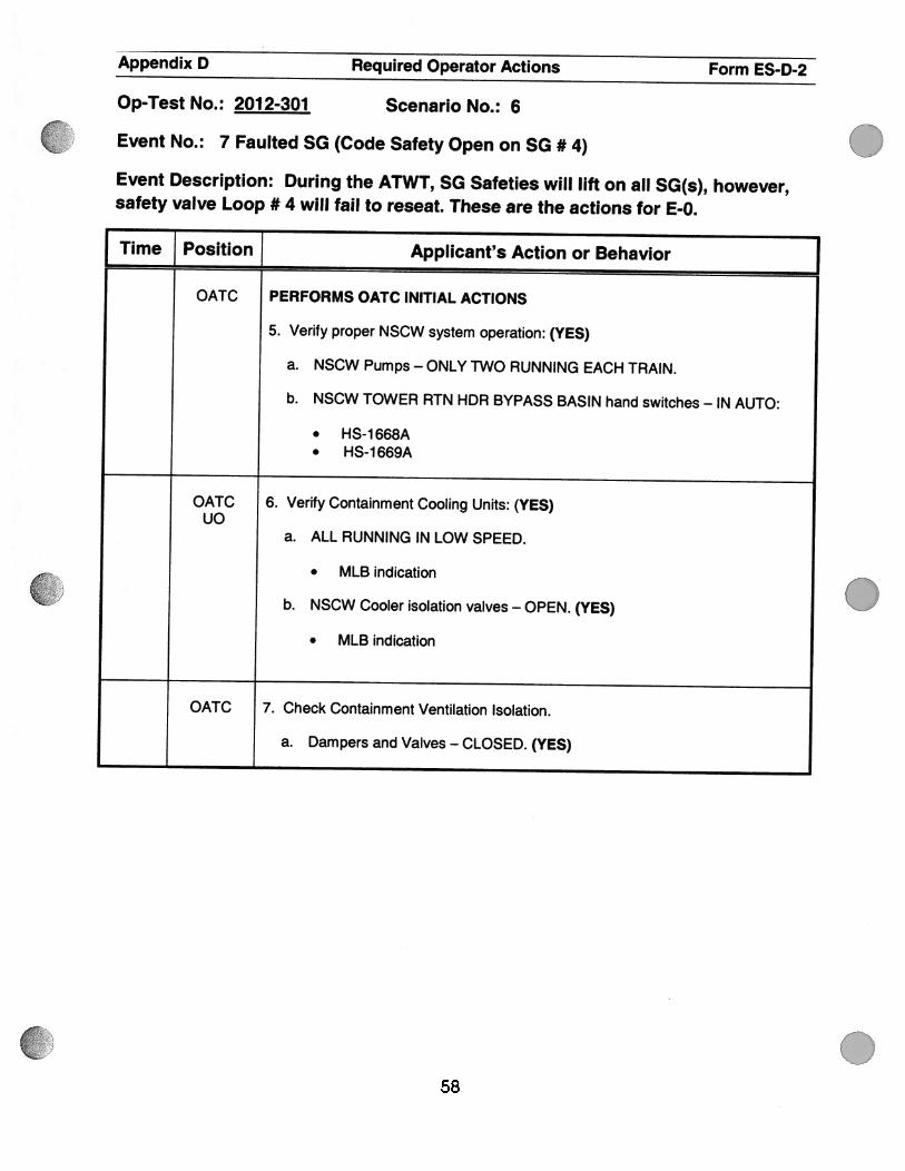
Time Position J Applicant’s Action or Behavior JOATC PERFORMS OATC INITIAL ACTIONS
5. Verify proper NSCW system operation: (YES)
a. NSCW Pumps - ONLY TWO RUNNING EACH TRAIN.
b. NSCW TOWER RTN HDR BYPASS BASIN hand switches - IN AUTO:
. HS-1668A• HS-1669A
OATC 6. Verify Containment Cooling Units: (YES)UO
a. ALL RUNNING IN LOW SPEED.
. MLB indication
b. NSCW Cooler isolation valves — OPEN. (YES)
. MLB indication
OATC 7. Check Containment Ventilation Isolation.
a. Dampers and Valves — CLOSED. (YES)
.
.58

.
Appendix D Required Operator Actions Form ES-D-2
Op-Test No.: 2012-301 Scenario No.: 6
Event No.: 7 Faulted SG (Code Safety Open on SG #4)
Event Description: During the ATWT, SG Safeties will lift on all SG(s), however,safety valve Loop # 4 will fail to reseat. These are the actions for E-0.
Time ] Position Applicant’s Action or Behavior
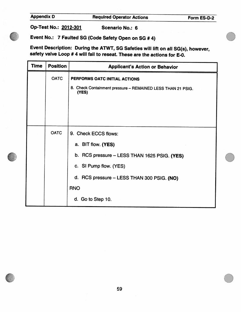
OATC PERFORMS OATC INITIAL ACTIONS
8. Check Containment pressure — REMAINED LESS THAN 21 PSIG.(YES)
OATC 9. Check ECCS flows:
a. BIT flow. (YES)
b. RCS pressure — LESS THAN 1625 PSIG. (YES)
c. SI Pump flow. (YES)
d. RCS pressure — LESS THAN 300 PSIG. (NO)
RNO
d. GotoSteplO.
.
.59

Appendix D Required Operator Actions Form ES-D-2
Op-Test No.: 2012-301 Scenario No.: 6
Event No.: 7 Faulted SG (Code Safety Open on SG #4)
Event Description: During the ATWT, SG Safeties will lift on all SG(s), however,safety valve Loop # 4 will fail to reseat. These are the actions for E-0.
.
.
.
Time Position } Applicant’s Action or Behavior
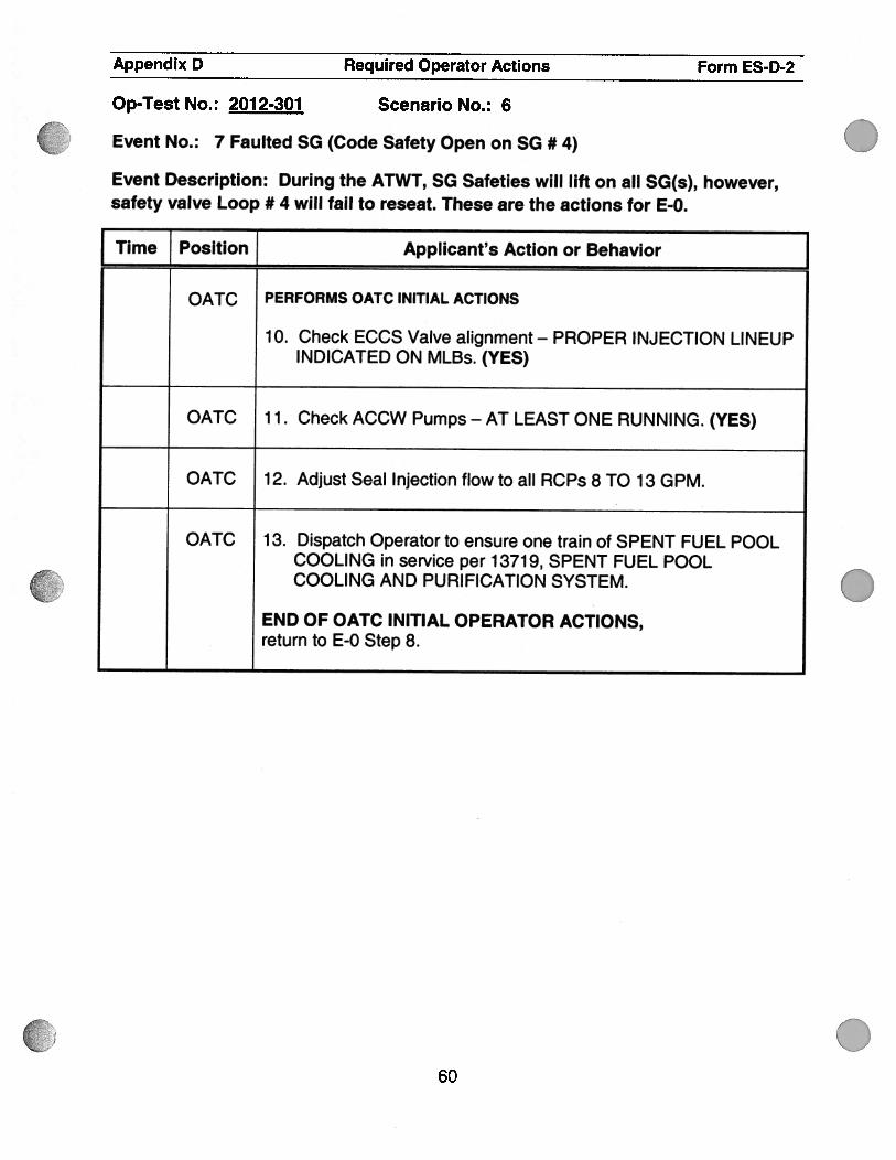
OATC PERFORMS OATC INITIAL ACTIONS
10. Check ECCS Valve alignment— PROPER INJECTION LINEUPINDICATED ON MLBs. (YES)
OATC 1 1 . Check ACCW Pumps - AT LEAST ONE RUNNING. (YES)
OATC 1 2. Adjust Seal Injection flow to all RCPs 8 TO 1 3 GPM.
OATC 1 3. Dispatch Operator to ensure one train of SPENT FUEL POOLCOOLING in service per 13719, SPENT FUEL POOLCOOLING AND PURIFICATION SYSTEM.
END OF OATC INITIAL OPERATOR ACTIONS,return to E-O Step 8.
60

.
.
Appendix D Required Operator Actions Form ES-D-2
Op-Test No.: 2012-301 Scenario No.: 6
Event No.: 7 Faulted SG (Code Safety Open on SG #4)
Event Description: During the ATWT, SG Safeties will lift on all SG(s), however,safety valve Loop # 4 will fail to reseat. These are the actions for E-0.
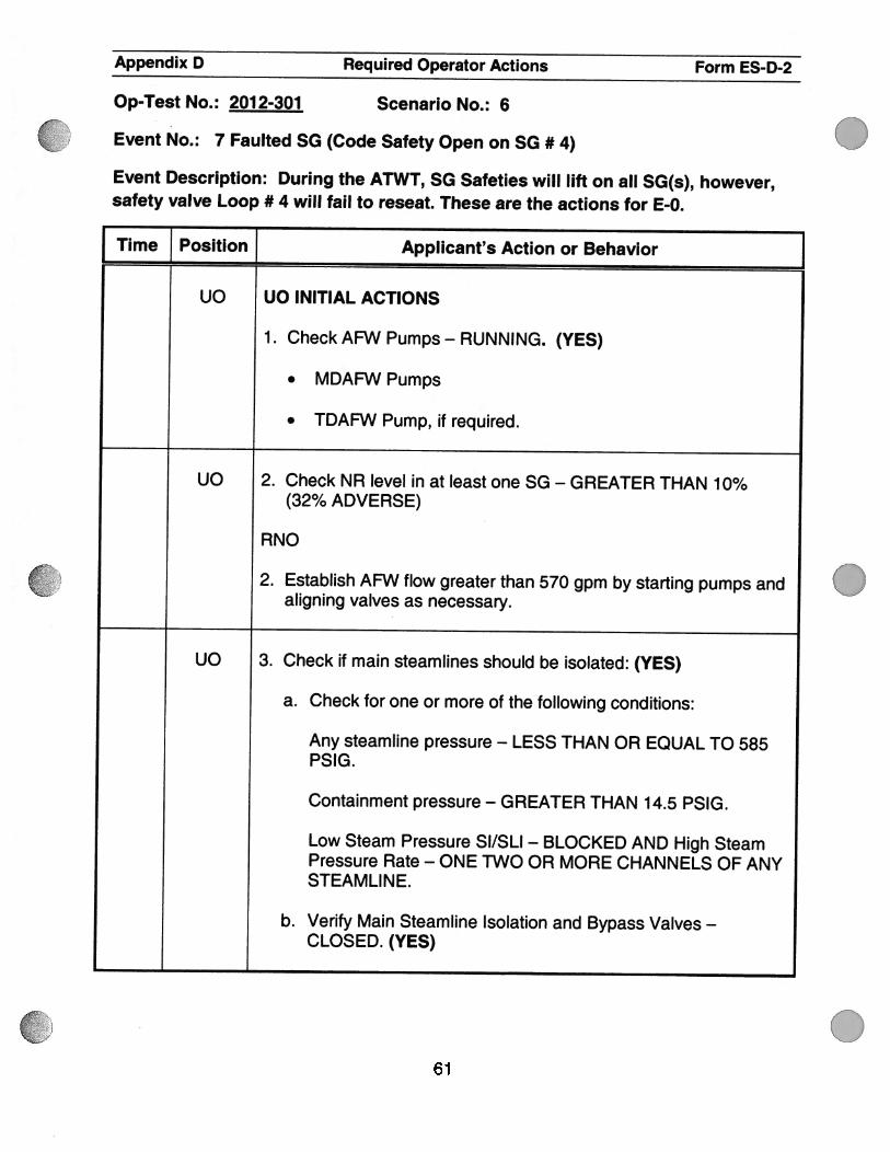
Time Position ] Applicant’s Action or Behavior ]uo uo INITIAL ACTIONS
1 . Check AFW Pumps - RUNNING. (YES)
. MDAFW Pumps
. TDAFW Pump, if required.
UO 2. Check NR level in at least one SG — GREATER THAN 10%(32% ADVERSE)
RNO
2. Establish AFW flow greater than 570 gpm by starting pumps andaligning valves as necessary.
UO 3. Check if main steamlines should be isolated: (YES)
a. Check for one or more of the following conditions:
Any steamline pressure — LESS THAN OR EQUAL TO 585P51G.
Containment pressure — GREATER THAN 14.5 P51G.
Low Steam Pressure SI/SLI — BLOCKED AND High SteamPressure Rate - ONE TWO OR MORE CHANNELS OF ANYSTEAMLINE.
b. Verify Main Steamline Isolation and Bypass Valves —
CLOSED. (YES)
0
061

Appendix D Required Operator Actions Form ES-D-2
Op-Test No.: 2012-301 Scenario No.: 6
Event No.: 7 Faulted SG (Code Safety Open on SG #4)
Event Description: During the ATWT, SG Safeties will lift on all SG(s), however,safety valve Loop # 4 will fail to reseat. These are the actions for E-0.
I Time Position [ Applicant’s Action or Behavior
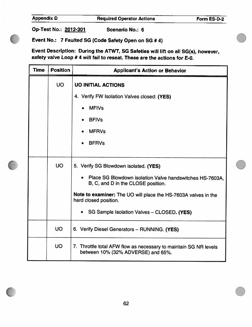
uo uo INITIAL ACTIONS
4. Verify FW Isolation Valves closed: (YES)
. MFIVs
. BFIVs
. MFRVs
. BFRVs
uc 5. Verify SG Blowdown isolated. (YES)
. Place SG Blowdown isolation Valve handswitches HS-7603A,B, C, and D in the CLOSE position.
Note to examiner: The UO will place the HS-7603A valves in thehard closed position.
• SG Sample Isolation Valves — CLOSED. (YES)
UO 6. Verify Diesel Generators — RUNNING. (YES)
UO 7. Throttle total AFW flow as necessary to maintain SG NR levelsbetween 10% (32% ADVERSE) and 65%.
.
.62

Appendix D Required Operator Actions Form ES-D-2
Op-Test No.: 201 2-301 Scenario No.: 6
Event No.: 7 Faulted SG (Code Safety Open on SG #4)
Event Description: During the ATWT, SG Safeties will lift on all SG(s), however,safety valve Loop # 4 will fail to reseat. These are the actions for E-0.
Time Position Applicant’s Action or Behavior
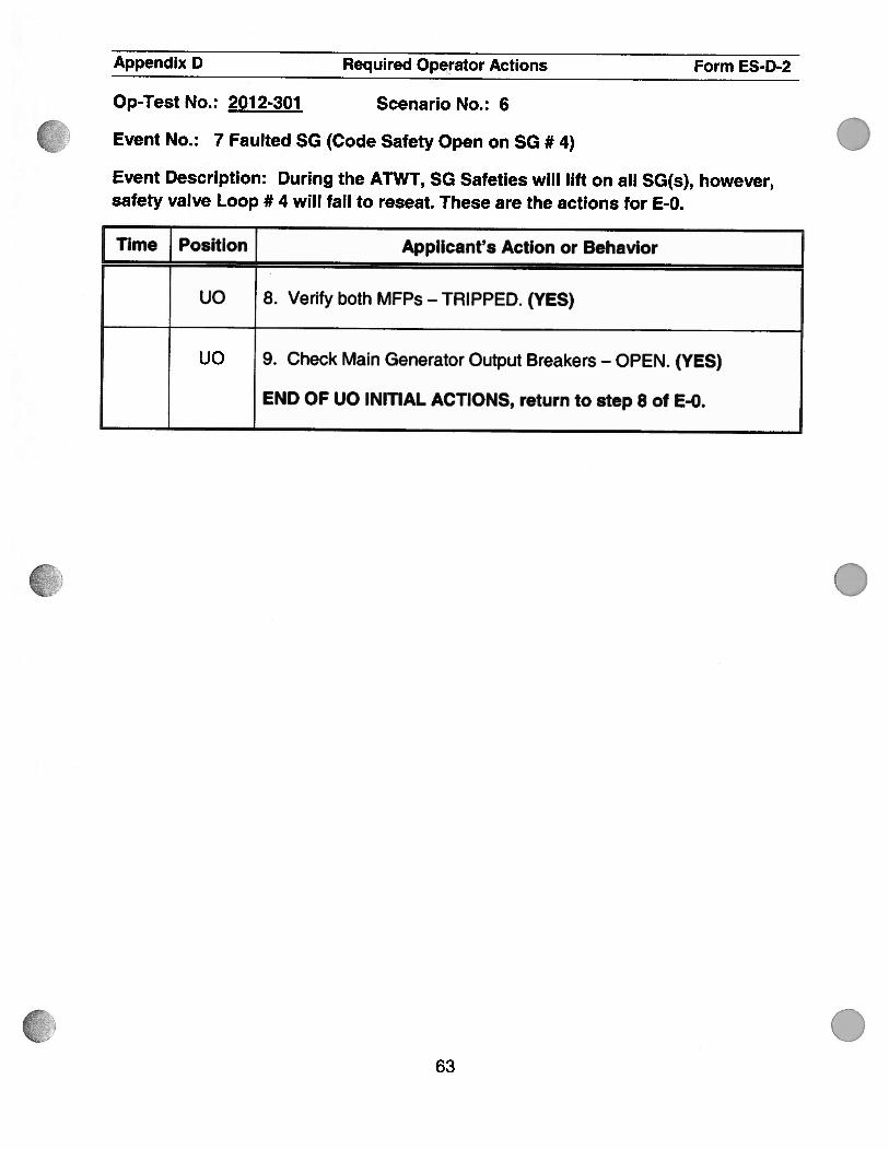
UO 8. Verify both MFPs — TRIPPED. (YES)
UO 9. Check Main Generator Output Breakers — OPEN. (YES)
END OF UO INITIAL ACTIONS, return to step 8 of E-0.
.
.
.63

Appendix D Required Operator Actions Form ES-D-2
Op-Test No.: 2012-301 Scenario No.: 6
Event No.: 7 Faulted SG (Code Safety Open on SG #4)
Event Description: During the ATWT, SG Safeties will lift on all SG(s), however,safety valve Loop # 4 will fail to reseat. These are the actions for E-0.
I Time Position Applicant’s Action or Behavior
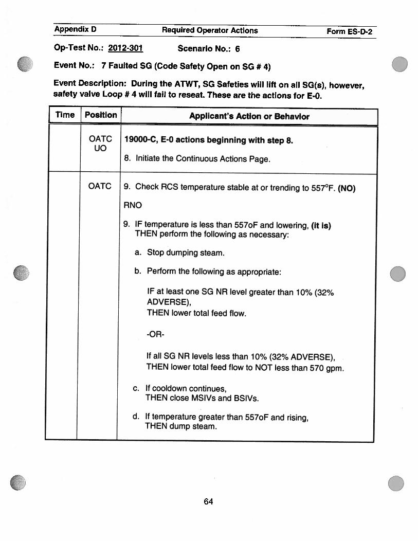
OATC 1 9000-C, E-0 actions beginning with step 8.uo
8. Initiate the Continuous Actions Page.
OATC 9. Check RCS temperature stable at or trending to 557°F. (NO)
RNO
9. IF temperature is less than 557oF and lowering, (it is)THEN perform the following as necessary:
a. Stop dumping steam.
b. Perform the following as appropriate:
IF at least one SG NR level greater than 10% (32%ADVERSE),THEN lower total feed flow.
-OR-
If all SG NR levels less than 10% (32% ADVERSE),THEN lower total feed flow to NOT less than 570 gpm.
c. If cooldown continues,THEN close MSlVs and BSIVs.
d. If temperature greater than 557oF and rising,THEN dump steam.
.
.64
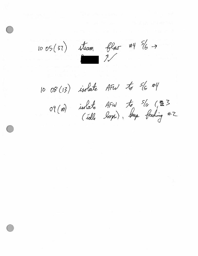
..
0
C
\p4
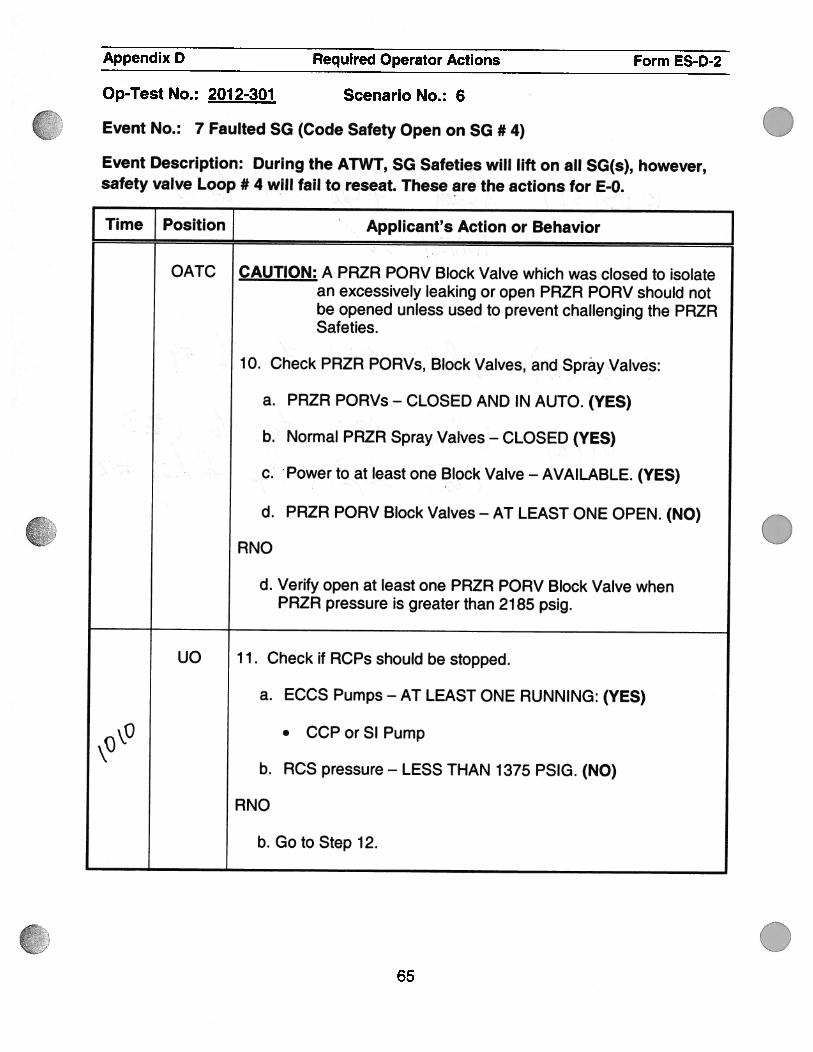
Appendix D Required Operator Actions Form ES-D-2
Op-Test No.: 2012-301 Scenario No.: 6
Event No.: 7 Faulted SG (Code Safety Open on SG #4)
Event Description: During the ATWT, SG Safeties will lift on all SG(s), however,safety valve Loop # 4 will fail to reseat. These are the actions for E-0.
Time Position Applicant’s Action or Behavior
OATC CAUTION: A PRZR PORV Block Valve which was closed to isolatean excessively leaking or open PRZR PORV should notbe opened unless used to prevent challenging the PRZRSafeties.
10. Check PRZR PORVs, Block Valves, and Spray Valves:
a. PRZR PORVs - CLOSED AND IN AUTO. (YES)
b. Normal PRZR Spray Valves — CLOSED (YES)
c. Power to at least one Block Valve — AVAILABLE. (YES)
d. PRZR PORV Block Valves — AT LEAST ONE OPEN. (NO)
RNO
d. Verify open at least one PRZR PORV Block Valve whenPRZR pressure is greater than 21 85 psig.
UO 1 1 . Check if RCPs should be stopped.
a. ECCS Pumps - AT LEAST ONE RUNNING: (YES)
O • CCPorSlPump
b. RCS pressure — LESS THAN 1375 PSIG. (NO)
RNO
b. Go to Step 12.
.
.65

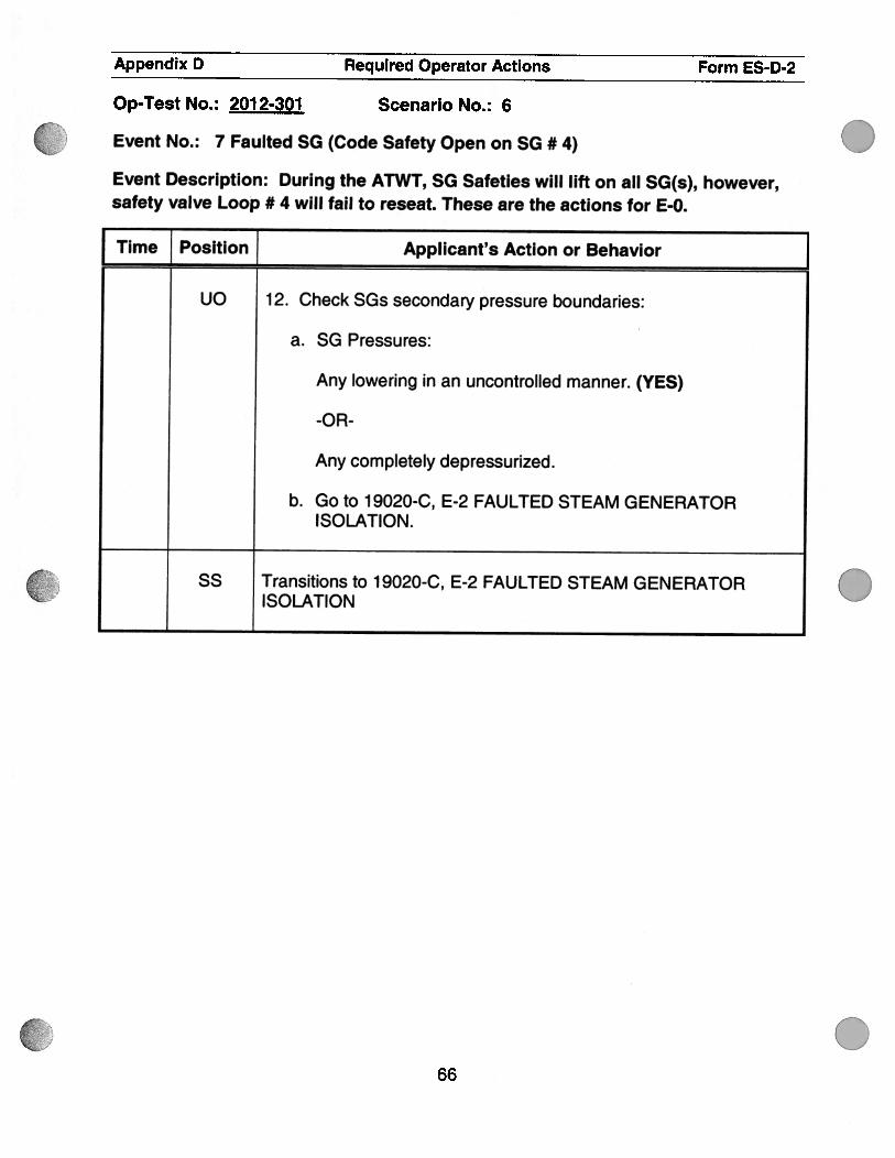
Appendix D Required Operator Actions Form ES-D-2
Op-Test No.: 2012-301 Scenario No.: 6
Event No.: 7 Faulted SG (Code Safety Open on SG #4)
Event Description: During the ATWT, SG Safeties will lift on all SG(s), however,safety valve Loop # 4 will fail to reseat. These are the actions for E-0.
Time Position] Applicant’s Action or Behavior
UO 12. Check SGs secondary pressure boundaries:
a. SG Pressures:
Any lowering in an uncontrolled manner. (YES)
-OR-
Any completely depressurized.
b. Go to 19020-C, E-2 FAULTED STEAM GENERATORISOLATION.
SS Transitions to 19020-C, E-2 FAULTED STEAM GENERATORISOLATION .
.66

7Y1A)io(
0
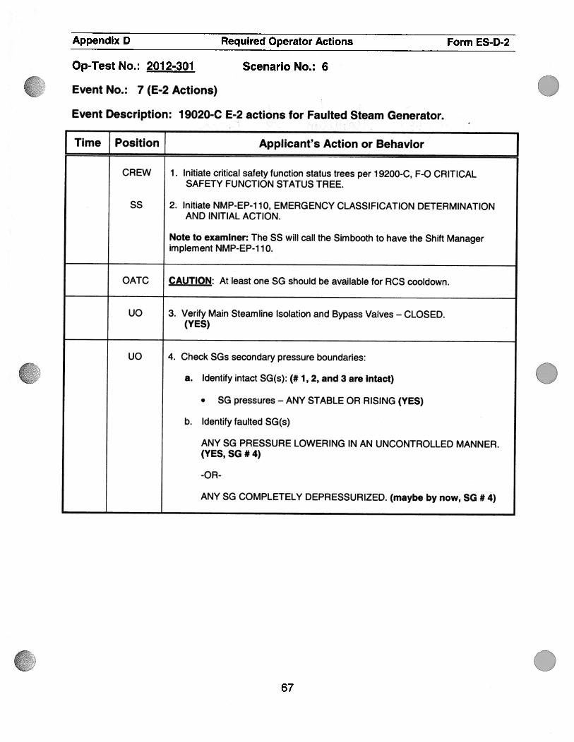
( .
.
.
Appendix D Required Operator Actions Form ES-D-2
Op-Test No. : 201 2-301 Scenario No. : 6
Event No. : 7 (E-2 Actions)
Event Description: 1 9020-C E-2 actions for Faulted Steam Generator.
Time { Position j Applicant’s Action or Behavior
CREW 1 . Initiate critical safety function status trees per 1 9200-C, F-C CRITICALSAFETY FUNCTION STATUS TREE.
55 2. Initiate NMP-EP-1 1 0, EMERGENCY CLASSIFICATION DETERMINATIONAND INITIAL ACTION.
Note to examiner: The SS will call the Simbooth to have the Shift Managerimplement NMP-EP-1 10.
OATC CAUTION: At least one SG should be available for RCS cooldown.
UO 3. Verify Main Steamline Isolation and Bypass Valves — CLOSED.(YES)
UO 4. Check SGs secondary pressure boundaries:
a. Identify intact SG(s): (# 1, 2, and 3 are intact)
• SG pressures - ANY STABLE OR RISING (YES)
b. Identify faulted SG(s)
ANY SG PRESSURE LOWERING IN AN UNCONTROLLED MANNER.(YES, SG #4)
-OR
ANY SG COMPLETELY DEPRESSURIZED. (maybe by now, SG #4)
67

to l
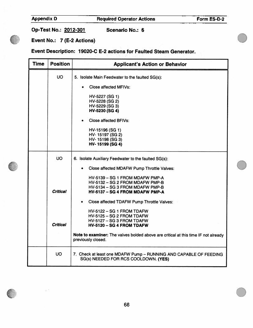
() .
.
.
Appendix D Required Operator Actions Form ESD-2
Op-Test No. : 201 2-301 Scenario No. : 6
Event No. : 7 (E.2 Actions)
Event Description: 19020-C E-2 actions for Faulted Steam Generator.
Time Position Applicant’s Action or Behavior
uo 5. Isolate Main Feedwater to the faulted SG(s):
. Close affected MFIVs:
HV-5227 (SG 1)HV-5228 (SG 2)HV-5229 (SG 3)HV523O (SG 4)
. Close affected BFIVs:
HV-15196 (SG 1)HV- 15197 (SG 2)HV- 15198 (SG 3)HV- 15199 (SG 4)
uo 6. Isolate Auxiliary Feedwater to the faulted SG(s):
. Close affected MDAFW Pump Throttle Valves:
HV-51 39 - SG 1 FROM MDAFW PMP-AHV-51 32 - SG 2 FROM MDAFW PMP-BHV-51 34 - SG 3 FROM MDAFW PMP-B
Critical HV-5137 - SG 4 FROM MDAFW PMP.A
. Close affected TDAFW Pump Throttle Valves:
HV-5122-SG 1 FROM TDAFWHV-5125 - SG 2 FROM TDAFWHV-5127 - SG 3 FROM TDAFW
Critical HV-5120 — SG 4 FROM TDAFW
Note to examiner: The valves bolded above are critical at this time IF not alreadypreviously closed.
UO 7. Check at least one MDAFW Pump - RUNNING AND CAPABLE OF FEEDINGSG(s) NEEDED FOR RCS COOLDOWN. (YES)
68

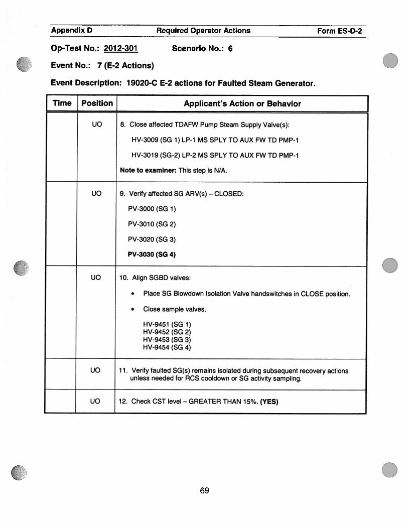
.
.
0
Appendix D Required Operator Actions Form ES-D-2
Op-Test No. : 201 2-301 Scenario No. : 6
Event No. : 7 (E-2 Actions)
Event Description: 19020-C E-2 actions for Faulted Steam Generator.
Time Position Applicant’s Action or Behavior
uo 8. Close affected TDAFW Pump Steam Supply Valve(s):
HV-3009 (SG 1 ) LP-1 MS SPLY TO AUX FW TD PM P-i
HV-3019 (SG-2) LP-2 MS SPLY TO AUX FW TD PMP-i
Note to examiner: This step is N/A.
uO 9. Verify affected SG ARV(s) — CLOSED:
PV-3000 (SG 1)
PV-30i0 (SG 2)
PV-3020 (SG 3)
PV-3030 (SG 4)
UO 10. Align SGBD valves:
. Place SG Blowdown Isolation Valve handswitches in CLOSE position.
. Close sample valves.
HV-945i (SG 1)HV-9452 (SG 2)HV-9453 (SG 3)HV-9454 (SG 4)
UO 11. Verify faulted SG(s) remains isolated during subsequent recovery actionsunless needed for RCS cooldown or SG activity sampling.
UO 12. Check CST level - GREATER THAN 15%. (YES)
69

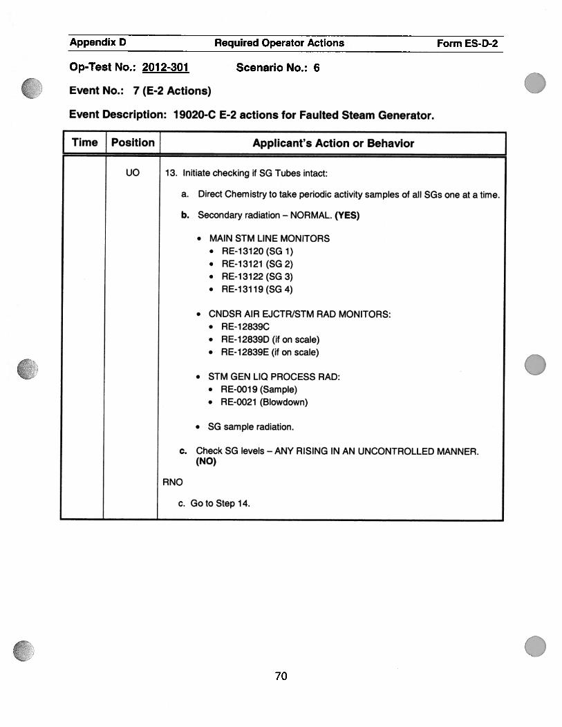
.
.
.
Appendix D Required Operator Actions Form ES-D-2
Op-Test No.: 2012-301 Scenario No.: 6
Event No. : 7 (E-2 Actions)
Event Description: 19020-C E-2 actions for Faulted Steam Generator.
[ Time J Position Applicant’s Action or Behavior
Uo 13. Initiate checking if SG Tubes intact:
a. Direct Chemistry to take periodic activity samples of all SGs one at a time.
b. Secondary radiation — NORMAL. (YES)
. MAIN STM LINE MONITORS. RE-13120(SG1). RE-13121 (SG 2). RE-13122(SG3). RE-13119(5G4)
• CNDSR AIR EJCTR/STM RAD MONITORS:• RE-12839C• RE-12839D (if on scale)• RE-12839E (if on scale)
• STM GEN LIQ PROCESS RAD:• RE-OO1 9 (Sample). RE-0021 (Blowdown)
. SG sample radiation.
c. Check SG levels — ANY RISING IN AN UNCONTROLLED MANNER.(NO)
RNO
c. GotoStepl4.
70

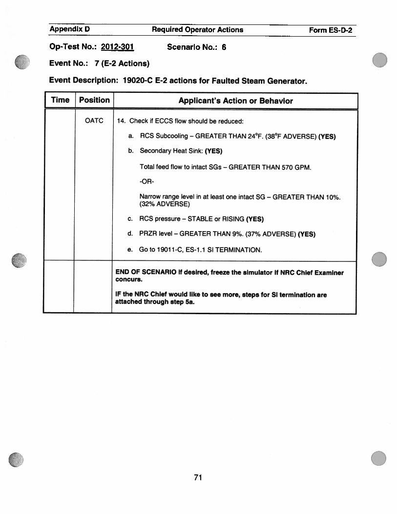
.
.
.
Appendix D Required Operator Actions Form ES-D-2
Op-Test No. : 201 2-301 Scenario No. : 6
Event No. : 7 (E-2 Actions)
Event Description: 1 9020-C E-2 actions for Faulted Steam Generator.
Time Position Applicant’s Action or Behavior
OATC 14. Check if ECCS flow should be reduced:
a. RCS Subcooling — GREATER THAN 24°F. (38°F ADVERSE) (YES)
b. Secondary Heat SAnk: (YES)
Total feed flow to intact SGs — GREATER THAN 570 GPM.
-OR-
Narrow range level in at least one intact SG — GREATER THAN 10%.(32% ADVERSE)
c. RCS pressure — STABLE or RISING (YES)
d. PRZR level — GREATER THAN 9%. (37% ADVERSE) (YES)
e. Goto 19011-C, ES-1.1 SI TERMINATION.
END OF SCENARIO if desired, freeze the simulator if NRC Chief Examinerconcurs.
IF the NRC Chief would like to see more, steps for SI termination areattached through step 5a.
71

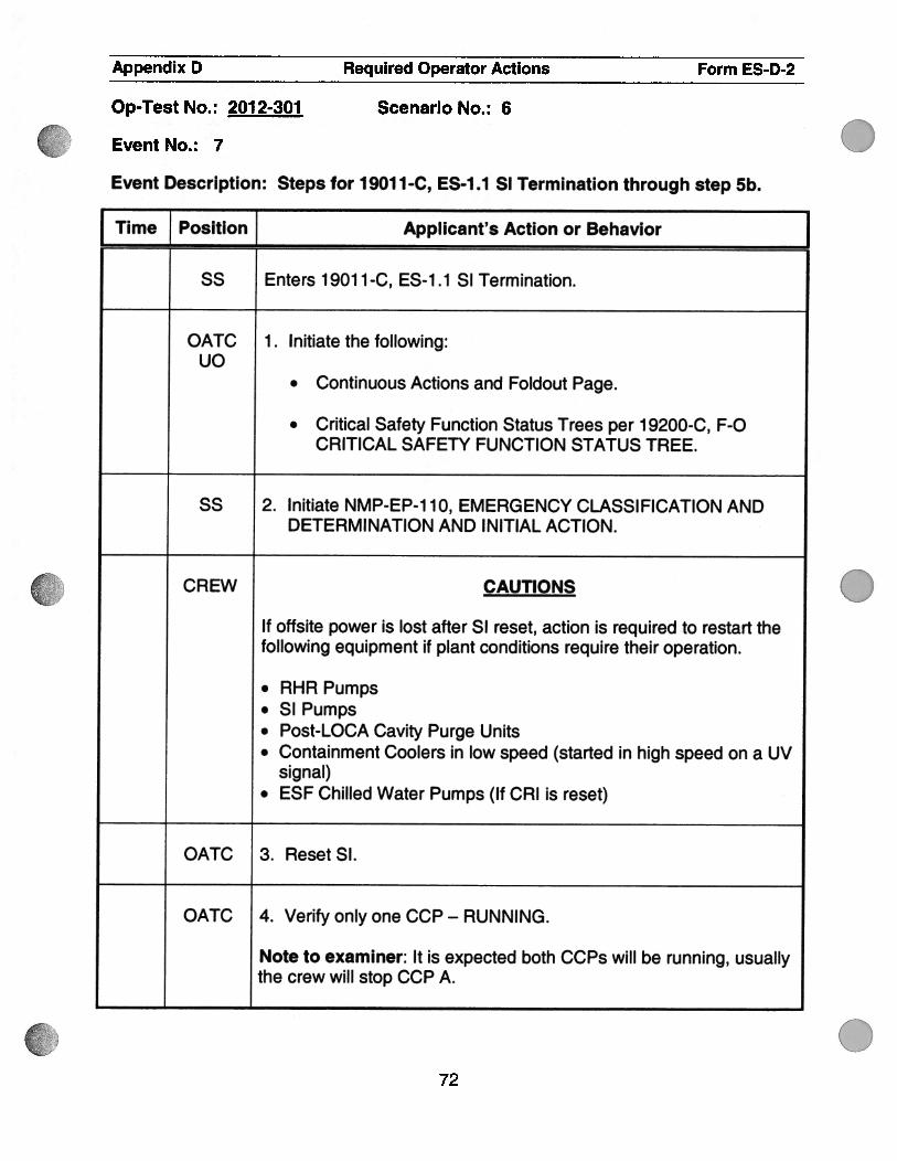
.
.
Appendix D Required Operator Actions Form ES-D-2
Op-Test No. : 201 2-301 Scenario No. : 6
EventNo.: 7
Event Description: Steps for 19011-C, ES-1.1 SI Termination through step 5b.
Time Position Applicant’s Action or Behavior Jss Enters 1901 1-C, ES-1.1 SI Termination.
OATC 1. Initiate the following:uo
. Continuous Actions and Foldout Page.
. Critical Safety Function Status Trees per 1 9200-C, F-CCRITICAL SAFETY FUNCTION STATUS TREE.
55 2. Initiate NMP-EP-1 10, EMERGENCY CLASSIFICATION ANDDETERMINATION AND INITIAL ACTION.
CREW CAUTIONS
If offsite power is lost after SI reset, action is required to restart thefollowing equipment if plant conditions require their operation.
. RHR Pumps
. SI Pumps
. Post-LOCA Cavity Purge Units
. Containment Coolers in low speed (started in high speed on a UVsignal)
. ESF Chilled Water Pumps (If CR1 is reset)
OATC 3. Reset SI.
OATC 4. VerifyonlyoneCCP-RUNNING.
Note to examiner: It is expected both CCPs will be running, usuallythe crew will stop CCP A.
72

0
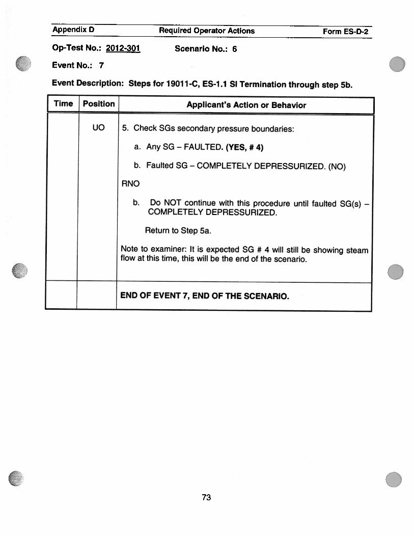
.
.
Appendix D Required Operator Actions Form ES-D2
Op-Test No. : 201 2-301 Scenario No. : 6
Event No. : 7
Event Description: Steps for 1 901 1 -C, ES-i .1 SI Termination through step 5b.
Time Position Applicant’s Action or Behavior
uo 5. Check SGs secondary pressure boundaries:
a. Any SG - FAULTED. (YES, #4)
b. Faulted SG — COMPLETELY DEPRESSURIZED. (NO)
RNO
b. Do NOT continue with this procedure until faulted SG(s) —
COMPLETELY DEPRESSURIZED.
Return to Step 5a.
Note to examiner: It is expected SG # 4 will still be showing steamflow at this time, this will be the end of the scenario.
END OF EVENT 7, END OF THE SCENARIO.
73
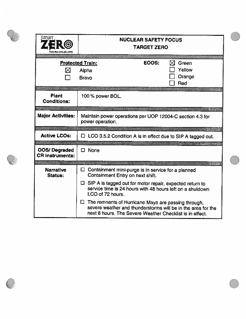
.
.
lan7ct NUCLEAR SAFETY FOCUSzR© TARGET ZEROEnry d .nryb. saIu#y
;..1i;?sMaz :ProtectedTrain: EOOS: Green
Alpha El Yellow
El Bravo j Orange
EJRed,J.
Plant 1 00 % power BOL.Conditions:
Major Activities: Maintain power operations per UOP 1 2004-C section 4.3 forpower operation.
Active LCOs: ci LCO 3.5.2 Condition A is in effect due to SIP A tagged out.
005/ Degraded D NoneCR Instruments:
Narrative ci Containment mini-purge is in service for a plannedStatus: Containment Entry on next shift.
D SIP A is tagged out for motor repair, expected return toservice time is 24 hours with 48 hours left on a shutdownLCO of 72 hours.
i: The remnants of Hurricane Maya are passing through,severe weather and thunderstorms will be in the area for thenext 8 hours. The Severe Weather Checklist is in effect.

g


![Binder Tab 02 - The Carla Smith Waiver Process [redacted]. · 05/12/2011 · Carla Smith (reference attached emails). Carla was the only applicant that was not recommended for a](https://static.fdocuments.us/doc/165x107/5f8911d7ca199069e909b413/binder-tab-02-the-carla-smith-waiver-process-redacted-05122011-carla-smith.jpg)


