Rectangular Standard Proximity Sensor TL-N/TL-Q CSM_TL-N_TL-Q_DS_E_10_3 Rectangular Standard...
12
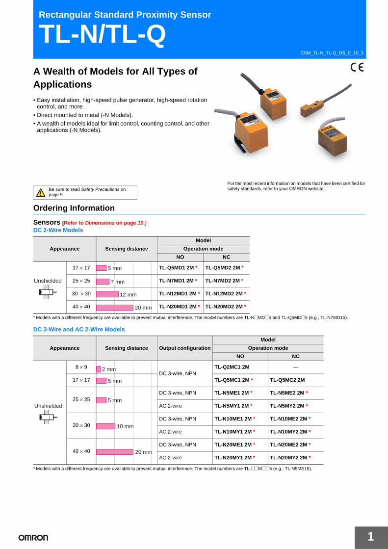
1 CSM_TL-N_TL-Q_DS_E_10_3 Rectangular Standard Proximity Sensor TL-N/TL-Q A Wealth of Models for All Types of Applications • Easy installation, high-speed pulse generator, high-speed rotation control, and more. • Direct mounted to metal (-N Models). • A wealth of models ideal for limit control, counting control, and other applications (-N Models). Be sure to read Safety Precautions on page 9. For the most recent information on models that have been certified for safety standards, refer to your OMRON website. Ordering Information Sensors [Refer to Dimensions on page 10.] DC 2-Wire Models * Models with a different frequency are available to prevent mutual interference. The model numbers are TL-N@MD@5 and TL-Q5MD@5 (e.g., TL-N7MD15). DC 3-Wire and AC 2-Wire Models * Models with a different frequency are available to prevent mutual interference. The model numbers are TL-@@M@@5 (e.g., TL-N5ME15). Appearance Sensing distance Model Operation mode NO NC 17 × 17 TL-Q5MD1 2M * TL-Q5MD2 2M * 25 × 25 TL-N7MD1 2M * TL-N7MD2 2M * 30 × 30 TL-N12MD1 2M * TL-N12MD2 2M * 40 × 40 TL-N20MD1 2M * TL-N20MD2 2M * Unshielded 5 mm 7 mm 12 mm 20 mm Appearance Sensing distance Output configuration Model Operation mode NO NC 8 × 9 DC 3-wire, NPN TL-Q2MC1 2M — 17 × 17 TL-Q5MC1 2M * TL-Q5MC2 2M 25 × 25 DC 3-wire, NPN TL-N5ME1 2M * TL-N5ME2 2M * AC 2-wire TL-N5MY1 2M * TL-N5MY2 2M * 30 × 30 DC 3-wire, NPN TL-N10ME1 2M * TL-N10ME2 2M * AC 2-wire TL-N10MY1 2M * TL-N10MY2 2M * 40 × 40 DC 3-wire, NPN TL-N20ME1 2M * TL-N20ME2 2M * AC 2-wire TL-N20MY1 2M * TL-N20MY2 2M * Unshielded 2 mm 5 mm 5 mm 10 mm 20 mm
Transcript of Rectangular Standard Proximity Sensor TL-N/TL-Q CSM_TL-N_TL-Q_DS_E_10_3 Rectangular Standard...
1
CSM_TL-N_TL-Q_DS_E_10_3
Rectangular Standard Proximity Sensor
TL-N/TL-QA Wealth of Models for All Types of Applications• Easy installation, high-speed pulse generator, high-speed rotation
control, and more.
• Direct mounted to metal (-N Models). • A wealth of models ideal for limit control, counting control, and other
applications (-N Models).
Be sure to read Safety Precautions on page 9.
For the most recent information on models that have been certified for safety standards, refer to your OMRON website.
Ordering Information
Sensors [Refer to Dimensions on page 10.]DC 2-Wire Models
* Models with a different frequency are available to prevent mutual interference. The model numbers are TL-N@MD@5 and TL-Q5MD@5 (e.g., TL-N7MD15).
DC 3-Wire and AC 2-Wire Models
* Models with a different frequency are available to prevent mutual interference. The model numbers are TL-@@M@@5 (e.g., TL-N5ME15).
Appearance Sensing distance
Model
Operation mode
NO NC
17 × 17 TL-Q5MD1 2M * TL-Q5MD2 2M *
25 × 25 TL-N7MD1 2M * TL-N7MD2 2M *
30 × 30 TL-N12MD1 2M * TL-N12MD2 2M *
40 × 40 TL-N20MD1 2M * TL-N20MD2 2M *
Unshielded
5 mm
7 mm
12 mm
20 mm
Appearance Sensing distance Output configuration
Model
Operation mode
NO NC
8 × 9DC 3-wire, NPN
TL-Q2MC1 2M —
17 × 17 TL-Q5MC1 2M * TL-Q5MC2 2M
25 × 25DC 3-wire, NPN TL-N5ME1 2M * TL-N5ME2 2M *
AC 2-wire TL-N5MY1 2M * TL-N5MY2 2M *
30 × 30DC 3-wire, NPN TL-N10ME1 2M * TL-N10ME2 2M *
AC 2-wire TL-N10MY1 2M * TL-N10MY2 2M *
40 × 40DC 3-wire, NPN TL-N20ME1 2M * TL-N20ME2 2M *
AC 2-wire TL-N20MY1 2M * TL-N20MY2 2M *
Unshielded
2 mm
5 mm
5 mm
10 mm
20 mm
2
TL-N/TL-Q
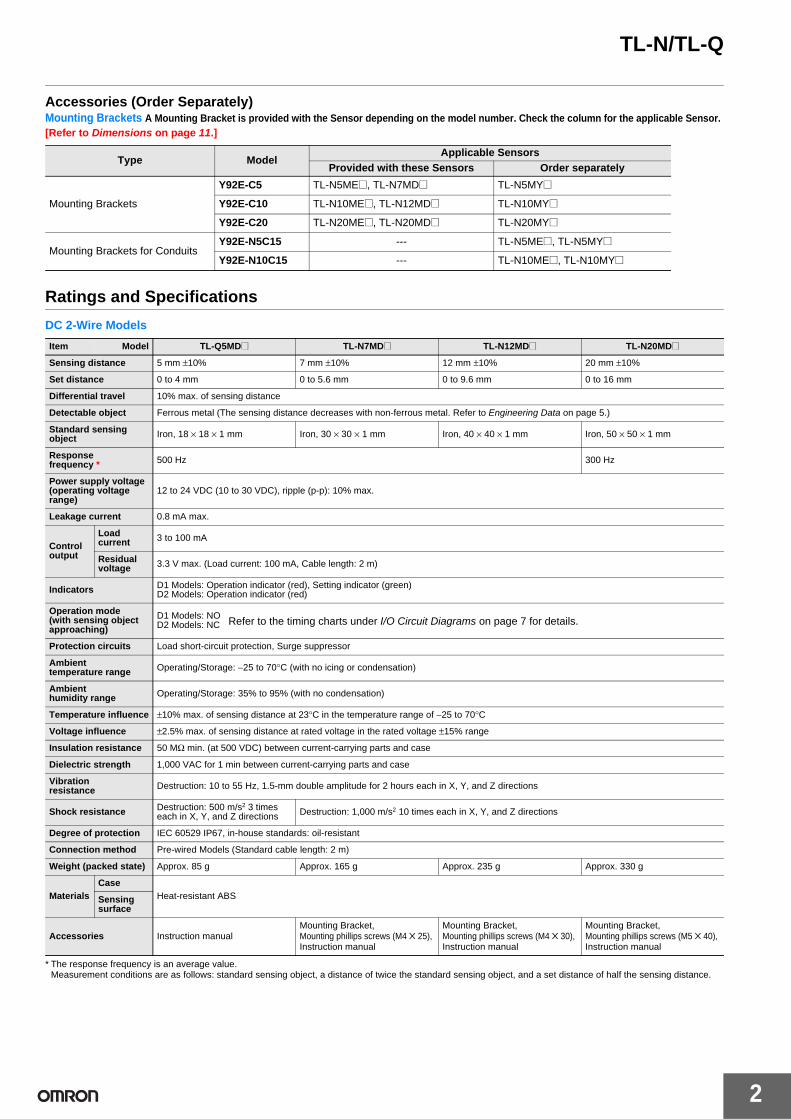
Accessories (Order Separately)Mounting Brackets A Mounting Bracket is provided with the Sensor depending on the model number. Check the column for the applicable Sensor. [Refer to Dimensions on page 11.]
Ratings and Specifications
DC 2-Wire Models
* The response frequency is an average value.Measurement conditions are as follows: standard sensing object, a distance of twice the standard sensing object, and a set distance of half the sensing distance.
Type ModelApplicable Sensors
Provided with these Sensors Order separately
Mounting Brackets
Y92E-C5 TL-N5ME@, TL-N7MD@ TL-N5MY@
Y92E-C10 TL-N10ME@, TL-N12MD@ TL-N10MY@
Y92E-C20 TL-N20ME@, TL-N20MD@ TL-N20MY@
Mounting Brackets for ConduitsY92E-N5C15 --- TL-N5ME@, TL-N5MY@
Y92E-N10C15 --- TL-N10ME@, TL-N10MY@
Item Model TL-Q5MD@ TL-N7MD@ TL-N12MD@ TL-N20MD@
Sensing distance 5 mm ±10% 7 mm ±10% 12 mm ±10% 20 mm ±10%
Set distance 0 to 4 mm 0 to 5.6 mm 0 to 9.6 mm 0 to 16 mm
Differential travel 10% max. of sensing distance
Detectable object Ferrous metal (The sensing distance decreases with non-ferrous metal. Refer to Engineering Data on page 5.)
Standard sensing object Iron, 18 × 18 × 1 mm Iron, 30 × 30 × 1 mm Iron, 40 × 40 × 1 mm Iron, 50 × 50 × 1 mm
Response frequency * 500 Hz 300 Hz
Power supply voltage (operating voltage range)
12 to 24 VDC (10 to 30 VDC), ripple (p-p): 10% max.
Leakage current 0.8 mA max.
Control output
Load current 3 to 100 mA
Residual voltage 3.3 V max. (Load current: 100 mA, Cable length: 2 m)
Indicators D1 Models: Operation indicator (red), Setting indicator (green)D2 Models: Operation indicator (red)
Operation mode(with sensing object approaching)
D1 Models: NOD2 Models: NC
Protection circuits Load short-circuit protection, Surge suppressor
Ambient temperature range Operating/Storage: −25 to 70°C (with no icing or condensation)
Ambient humidity range Operating/Storage: 35% to 95% (with no condensation)
Temperature influence ±10% max. of sensing distance at 23°C in the temperature range of −25 to 70°C
Voltage influence ±2.5% max. of sensing distance at rated voltage in the rated voltage ±15% range
Insulation resistance 50 MΩ min. (at 500 VDC) between current-carrying parts and case
Dielectric strength 1,000 VAC for 1 min between current-carrying parts and case
Vibration resistance Destruction: 10 to 55 Hz, 1.5-mm double amplitude for 2 hours each in X, Y, and Z directions
Shock resistance Destruction: 500 m/s2 3 times each in X, Y, and Z directions Destruction: 1,000 m/s2 10 times each in X, Y, and Z directions
Degree of protection IEC 60529 IP67, in-house standards: oil-resistant
Connection method Pre-wired Models (Standard cable length: 2 m)
Weight (packed state) Approx. 85 g Approx. 165 g Approx. 235 g Approx. 330 g
MaterialsCase
Heat-resistant ABSSensing surface
Accessories Instruction manualMounting Bracket, Mounting phillips screws (M4 ✕ 25), Instruction manual
Mounting Bracket, Mounting phillips screws (M4 ✕ 30), Instruction manual
Mounting Bracket, Mounting phillips screws (M5 ✕ 40), Instruction manual
Refer to the timing charts under I/O Circuit Diagrams on page 7 for details.
TL-N/TL-Q
3
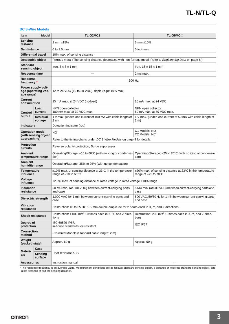
DC 3-Wire Models
* The response frequency is an average value. Measurement conditions are as follows: standard sensing object, a distance of twice the standard sensing object, and a set distance of half the sensing distance.
Item Model TL-Q2MC1 TL-Q5MC@
Sensing distance 2 mm ±15% 5 mm ±10%
Set distance 0 to 1.5 mm 0 to 4 mm
Differential travel 10% max. of sensing distance
Detectable object Ferrous metal (The sensing distance decreases with non-ferrous metal. Refer to Engineering Data on page 6.)
Standard sensing object Iron, 8 × 8 × 1 mm Iron, 15 × 15 × 1 mm
Response time --- 2 ms max.
Responsefrequency * 500 Hz
Power supply volt-age (operating volt-age range)
12 to 24 VDC (10 to 30 VDC), ripple (p-p): 10% max.
Current consumption 15 mA max. at 24 VDC (no-load) 10 mA max. at 24 VDC
Control output
Load current
NPN open collector100 mA max. at 30 VDC max.
NPN open collector50 mA max. at 30 VDC max.
Residual voltage
1 V max. (under load current of 100 mA with cable length of 2 m)
1 V max. (under load current of 50 mA with cable length of 2 m)
Indicators Detection indicator (red)
Operation mode(with sensing object approaching)
NO C1 Models: NOC2 Models: NC
Refer to the timing charts under DC 3-Wire Models on page 8 for details.
Protection circuits Reverse polarity protection, Surge suppressor
Ambient temperature range
Operating/Storage: −10 to 60°C (with no icing or condensa-tion)
Operating/Storage: −25 to 70°C (with no icing or condensa-tion)
Ambient humidity range Operating/Storage: 35% to 95% (with no condensation)
Temperature influence
±10% max. of sensing distance at 23°C in the temperature range of −10 to 60°C
±20% max. of sensing distance at 23°C in the temperature range of −25 to 70°C
Voltage influence ±2.5% max. of sensing distance at rated voltage in rated voltage ±10% range
Insulation resistance
50 MΩ min. (at 500 VDC) between current-carrying parts and case
5 MΩ min. (at 500 VDC) between current-carrying parts and case
Dielectric strength 1,000 VAC for 1 min between current-carrying parts and case
500 VAC, 50/60 Hz for 1 min between current-carrying parts and case
Vibration resistance Destruction: 10 to 55 Hz, 1.5-mm double amplitude for 2 hours each in X, Y, and Z directions
Shock resistance Destruction: 1,000 m/s2 10 times each in X, Y, and Z direc-tions
Destruction: 200 m/s2 10 times each in X, Y, and Z direc-tions
Degree of protection
IEC 60529 IP67, in-house standards: oil-resistant IEC IP67
Connection method Pre-wired Models (Standard cable length: 2 m)
Weight (packed state) Approx. 60 g Approx. 90 g
Materi-als
CaseHeat-resistant ABSSensing
surface
Accessories Instruction manual ---

4
TL-N/TL-Q
*1. The response frequency is an average value. Measurement conditions are as follows: standard sensing object, a distance of twice the standard sensing object, and a set distance of half the sensing distance.
*2. E Models (DC switching models): A full-wave rectification power supply of 24 VDC ±10% (average value) can be used.
Item Model TL-N5ME@, TL-N5MY@ TL-N10ME@, TL-N10MY@ TL-N20ME@, TL-N20MY@
Sensing distance 5 mm ±10% 10 mm ±10% 20 mm ±10%
Set distance 0 to 4 mm 0 to 8 mm 0 to 16 mm
Differential travel 15% max. of sensing distance
Detectable object Ferrous metal (The sensing distance decreases with non-ferrous metal. Refer to Engineering Data on pages 6 and 7.)
Standard sensing object Iron, 30 × 30 × 1 mm Iron, 40 × 40 × 1 mm Iron, 50 × 50 × 1 mm
Response frequency *1
E Models: 500 HzY Models: 10 Hz
E Models: 40 HzY Models: 10 Hz
Power supply voltage *2 (operating voltage range)
E Models: 12 to 24 VDC (10 to 30 VDC), ripple (p-p): 10% max.Y Models: 100 to 220 VAC (90 to 250 VAC), 50/60 Hz
Current consumption E Models: 8 mA max. at 12 VDC, 15 mA max. at 24 VDC
Leakage current Y Models: Refer to Engineering Data on page 5.
Control output
Load current
E Models: 100 mA max. at 12 VDC, 200 mA max. at 24 VDCY Models: 10 to 200 mA
Residual voltage
E Models: 1 V max. (load current: 200 mA)Y Models: Refer to Engineering Data on page 5.
Indicators E Models: Detection indicator (red)Y Models: Operation indicator (red)
Operation mode (with sensing ob-ject approaching)
E1/Y1 Models: NOE2/Y2 Models: NC
Refer to the timing charts under I/O Circuit Diagrams on page 8 for details.
Protection circuits E Models: Reverse polarity protection, Surge suppressorY Models: Surge suppressor
Ambient temperature range Operating/Storage: −25 to 70°C (with no icing or condensation)
Ambienthumidity range Operating/Storage: 35% to 95% (with no condensation)
Temperature influence ±10% max. of sensing distance at 23°C in the temperature range of −25 to 70°C
Voltage influence E Models: ±2.5% max. of sensing distance at rated voltage in rated voltage ±10% rangeY Models: ±1% max. of sensing distance at rated voltage in rated voltage ±10% range
Insulation resistance 50 MΩ min. (at 500 VDC) between current-carrying parts and case
Dielectric strength E Models: 1,000 VAC, 50/60 Hz for 1 min between current-carrying parts and caseY Models: 2,000 VAC, 50/60 Hz for 1 min between current-carrying parts and case
Vibration resistance Destruction: 10 to 55 Hz, 1.5-mm double amplitude for 2 hours each in X, Y, and Z directions
Shock resistance Destruction: 500 m/s2 10 times each in X, Y, and Z directions
Degree ofprotection IEC 60529 IP67, in-house standards: oil-resistant
Connection method Pre-wired Models (Standard cable length: 2 m)
Weight (packed state) Approx. 190 g Approx. 240 g Approx. 340 g
Materi-als
CaseHeat-resistant ABSSensing
surface
Accessories
E Models: Mounting Bracket, Mounting phillips screws (M4 ✕ 25), Instruction manual
Y Models: Instruction manual
E Models: Mounting Bracket, Mounting phillips screws (M4 ✕ 30), Instruction manual
Y Models: Instruction manual
E Models: Mounting Bracket, Mounting phillips screws (M5 ✕ 40), Instruction manual
Y Models: Instruction manual

TL-N/TL-Q
5
Engineering Data (Reference Value)
Sensing Area
TL-Q2MC1 TL-Q5M@@ TL-N@ME@TL-N@MY@
Leakage Current
TL-N@MD@ TL-N@MY
Residual Output Voltage
TL-N@MD TL-N@MY at 100 VAC TL-N@MY at 200 VAC
4
3
2
1
0−8 −6 −4 −2 0 2 4 6
YX
Dis
tanc
e X
(m
m)
Distance Y (mm)Sensing Head
5
4
3
2
1
0 −8 −6 −4 −2 0 2 4 6 8
YX
Dis
tanc
e X
(m
m)
Distance Y (mm)Sensing Head
TL-N5
TL-N10
20
15
10
5
0
TL-N20
−25 −20 −15 −10 −5 0 5 10 15 20
YX
Dis
tanc
e X
(m
m)
Distance Y (mm)TL-N5 Sensing HeadTL-N10 Sensing HeadTL-N20 Sensing Head
TL-N7MD@
20
15
10
5
0-25 -20 -15 -10 -5 0 5 10 15 20
TL-N12MD@
TL-N20MD@
YX
Dis
tanc
e X
(m
m)
Distance Y (mm)TL-N7MD@ Sensing HeadTL-N12MD@ Sensing HeadTL-N20MD@ Sensing Head
2.0
1.5
1.0
0.5
0 80 100 120 140 160 180 200 220 240 260
mA
V
Leak
age
curr
ent (
mA
)
Power supply voltage (V)
AC power 50/60 Hz
Protective resistance
Proximity Sensor (output OFF)
5
4
3
2
1
0 3 5 10 30 50 100 300 500 1,000
Res
idua
l out
put v
olta
ge (
V)
Load current (mA)
A
100
80
60
40
20
0 3 5 10 20 30 50 100 200OFF
100 VAC
V
ON
Load
vol
tage
VL
(V)
Load current (mA)
Residual load voltage
Residual output voltage
200
160
120
80
40
0OFF
3 5 10 20 50 100 200
V
A200 VAC
ON
Load
vol
tage
VL
(V)
Load current (mA)
Residual load voltage
Residual output voltage

6
TL-N/TL-Q
Sensing Object Size vs. Sensing Distance
TL-Q5MC@
Influence of Sensing Object Size and Material
TL-Q2MC1 TL-Q5M@@ TL-N5@
TL-N7MD@ TL-N12MD@ TL-N20MD@
7
6
5
4
3
2
1
0 10 20 30 40
t = 1 mm
X
Dis
tanc
e X
(m
m)
Side length of sensing object: d (mm)
d × d
4
3
2
1
0 10 20 30 40 50 60
X
d × d
Dis
tanc
e X
(m
m)
Side length of sensing object: d (mm)
Stainless steel (SUS304)
Aluminum
Iron
Copper
Brass
6
5
4
3
2
1
0 5 10 15 20 25 30 35 40 45
X
d × d
Dis
tanc
e X
(m
m)
Side length of sensing object: d (mm)
Stainless steel (SUS304)
Aluminum
Iron
Brass
6
5
4
3
2
1
0 10 20 30 40 50 60 70 80
X
d × d t = 1 mm
Dis
tanc
e X
(m
m)
Side length of sensing object: d (mm)
Stainless steel (SUS304)
Aluminum
Iron
Brass
10
8
6
4
2
0 10 20 30 40 50 60
X
d × d
t = 1 mm
Dis
tanc
e X
(m
m)
Side length of sensing object: d (mm)
Stainless steel (SUS304)
Aluminum
Iron
Copper
Brass
14
12
10
8
6
4
2
0 10 20 30 40 50 60
X
d × d t = 1 mm
Dis
tanc
e X
(m
m)
Side length of sensing object: d (mm)
Aluminum
Iron
Copper
Brass
Stainless steel (SUS304)
24
20
16
12
8
4
0 10 20 30 40 50 60
X
d × d t = 1 mm
Dis
tanc
e X
(m
m)
Side length of sensing object: d (mm)
Aluminum
Iron
Copper
Brass
Stainless steel (SUS304)

TL-N/TL-Q
7
I/O Circuit Diagrams
DC 2-Wire Models
TL-N10@ TL-N20@
10
8
6
4
2
0 10 20 30 40 50 60 70 80
X
d × d t = 1 mm
Dis
tanc
e X
(m
m)
Side length of sensing object: d (mm)
Stainless steel (SUS304)
Aluminum
Iron
Brass
22
20
18
16
14
12
10
8
6
4
2
0 10 20 30 40 50 60 70 80
X
d × d t = 1 mm
Dis
tanc
e X
(m
m)
Side length of sensing object: d (mm)
Stainless steel (SUS304)
Aluminum
Iron
Brass
Operation mode Model Timing chart Output circuit
NO
TL-Q5MD1TL-N7MD1TL-N12MD1TL-N20MD1
NC
TL-Q5MD2TL-N7MD2TL-N12MD2TL-N20MD2
080 (TYP)100(%)
Sensing object
Rated sensing distance
Stable sensing area
Non-sensing area
Unstable sensing area
Set position
Proximity Sensor
ON
OFF
ON
OFF
ON
OFF
Setting indicator (green)
Operation indicator (red)
Control output
+V
0 V
LoadBrown
Blue
Proximity Sensor main circuit
Note: The load can be connected to either the +V or 0 V side.
0100(%)
Sensing object
Rated sensing distance
Sensing area
Non-sensing area
Proximity Sensor
ON
OFF
ON
OFF
Operation indicator (red)
Control output

8
TL-N/TL-Q
DC 3-Wire Models
AC 2-Wire Models
Operation mode Model Timing chart Output circuit
NO TL-Q2MC1TL-Q5MC1
NC TL-Q5MC2
NOTL-N5ME1TL-N10ME1TL-N20ME1
NCTL-N5ME2TL-N10ME2TL-N20ME2
Operation mode Model Timing chart Output circuit
NOTL-N5MY1TL-N10MY1TL-N20MY1
NCTL-N5MY2TL-N10MY2TL-N20MY2
Present
Not present
ON
OFF
ON
OFF
Output transistor (load)
Sensing object
Detection indicator (red) 100 Ω
0 V
+V
*Load
Brown
Black
Output
Blue
Proximity Sensor
main circuit
* Load current: 100 mA max., TL-Q2MC1Load current: 50 mA max., TL-Q5MC1
Present
Not present
ON
OFF
ON
OFF
Output transistor (load)
Sensing object
Detection indicator (red)
Present
Not present
Operate
Reset
High
Low
ON
OFF
Load (between brown and black leads)
Sensing object
Detection indicator (red)
Output voltage (between black and blue leads)
2.2 Ω
4.7 kΩ
100 Ω
0 V
Tr
+V
*1
Load
Brown
Black
*1. Load current: 200 mA max.
*2. When a transistor is connected.
Output *2
Blue
Proximity Sensor
main circuit
Present
Not present
Operate
Reset
High
Low
ON
OFF
Load (between brown and black leads)
Sensing object
Detection indicator (red)
Output voltage (between black and blue leads)
Present
Not present
Operate
Reset
ON
OFF
Load
Sensing object
Operation indicator (red)
Brown
Blue
Load
Proximity Sensor
main circuit
Present
Not present
Operate
Reset
ON
OFF
Load
Sensing object
Operation indicator (red)

TL-N/TL-Q
9
Safety Precautions
Refer to Warranty and Limitations of Liability.
This product is not designed or rated for ensuring safety of persons either directly or indirectly.Do not use it for such purposes.
• Do not short-circuit the load, otherwise the Sensor may be damaged.
• Do not supply power to the Sensor with no load, otherwise the Sensor may be damaged. Applicable Models: AC 2-Wire Models
Do not use this product under ambient conditions that exceed the ratings. ● Design
Influence of Surrounding MetalWhen mounting the Sensor within a metal panel, ensure that the clearances given in the following table are maintained. Failure to maintain these distances may cause deterioration in the performance of the Sensor.
Influence of Surrounding Metal (Unit: mm)
*1. The B dimension applies to the top, right-side, and left-side surfaces.*2. The values for A or B for the TL-N apply when there is metal on only one side
of the sensor. If there is metal on two or more sides of the sensor, the value must be multiplied by two or more.
Influence of Surrounding Metal (Unit: mm)
Mutual InterferenceWhen installing Sensors face-to-face or side-by-side, ensure that the minimum distances given in the following table are maintained.
Mutual Interference (Unit: mm)
* Values in parentheses apply to Sensors operating at different frequencies.
Mutual Interference (Unit: mm)
* Values in parentheses apply to Sensors operating at different frequencies.
● MountingWhen tightening the mounting screws, do not exceed the torque in the following table.
WARNING
Precautions for Correct Use
Model Distance A B *1TL-Q5M@@ 20 20TL-N7MD@ 40 35TL-N12MD@ 50 40TL-N20MD@ 70 60TL-N5ME@, TL-N5MY@ 20 23TL-N10ME@, TL-N10MY@ 40 30TL-N20ME@, TL-N20MY@ 80 45
Model Distance A BTL-Q2MC1 12 3
A
B
TL-N*2
*1
Rectangular Models TL-Q
A
B*1
A
3 mm
TL-Q2MC1
* The mounting plate must be a non-ferrous metal.
Mounting plate*
B
BTL-Q2MC1
Model Distance A * B *TL-Q5MC@ 60 (17) 120 (60)TL-Q5MD@ 60 (30) 120 (80)TL-N7MD@ 100 (50) 120 (60)TL-N12MD@ 120 (60) 200 (100)TL-N20MD@ 200 (100) 200 (100)TL-N5ME@ 80 (40) 80 (40)TL-N5MY@ 80 (40) 90 (40)TL-N10ME@, TL-N10MY@ 120 (60) 120 (60)TL-N20ME@, TL-N20MY@ 200 (100) 120 (60)
Model Distance A * B *TL-Q2MC1 30 (8) 90 (45)
A
B
Parallel Face-to-face
B
A
Model TorqueTL-Q2MC1
0.59 N·mTL-Q5M@@TL-N@M@@ 0.9 to 1.5 N·m

10
TL-N/TL-QDimensions
Sensors
(Unit: mm)Tolerance class IT16 applies to dimensions in this data sheet unless otherwise specified.
TL-Q2MC1
8
2.5
28
25
89
1*
6
18.5±0.2Sensing surface 3.2-dia. mounting hole
Detection indicator (red)
* 2.9-dia. vinyl-insulated round cable with 3 conductors (Conductor cross section: 0.15 mm2, Insulator diameter: 0.9 mm), Standard length: 2 m
TL-Q5M@@
163
17
17
10.5±0.1
*13.5
28
Two, 3.3 dia.
10.5±0.1
32 max.
Two, 3.3-dia. holesIndicators *2
*1. C Models: 4-dia. vinyl-insulated round cable with 3 conductors (Conductor cross section: 0.2 mm2, Insulator diameter: 1.2 mm), Standard length: 2 m D Models: 4-dia. vinyl-insulated round cable with 2 conductors (Conductor cross section: 0.3 mm2, Insulator diameter: 1.3 mm), Standard length: 2 m
*2. C Models: Detection indicator (red) D Models: Operation indicator (red), Setting indicator (green)
Mounting Hole Dimensions
TL-N7MD@, TL-N5ME@
23.8
18.5
0.5
25
25
6
35 Two, 4.3 dia.
18±0.45
*1
38.518.5
1.518±0.2
Indicator *2
Rubber bushing
*1. D Models: 6-dia. vinyl-insulated round cable with 2 conductors (Conductor cross section: 0.5 mm2, Insulator diameter: 1.9 mm), Standard length: 2 m E Models: 6-dia. vinyl-insulated round cable with 3 conductors (Conductor cross section: 0.5 mm2, Insulator diameter: 1.9 mm), Standard length: 2 m
*2. D1 Models: Operation indicator (red), Setting indicator (green) D2 Models: Operation indicator (red) E Models: Detection indicator (red)
Two, 4.5-dia. or M4 holes
9 dia.8 dia.
Mounting Hole Dimensions
18.5
0.5
25
6.2
25
18±0.2 50
*
1.5
34.1
46.3 Two, 4.3 dia.
18±0.45
18.5
9 dia.8 dia.Operation indicator (red)
Rubber bushing
* 6-dia. vinyl-insulated round cable with 2 conductors (Conductor cross section: 0.5 mm2, Insulator diameter: 1.9 mm), Standard length: 2 m
Two, 4.5-dia. or M4 holes
TL-N5MY@
Mounting Hole Dimensions
35.8
21.5
52.50.5
30
30
7.7
22±0.45
48.5 Two, 4.3 dia.
*1
1.5
22±0.2
Rubber bushing
*1. D/Y Models: 6-dia. vinyl-insulated round cable with 2 conductors (Conductor cross section: 0.5 mm2, Insulator diameter: 1.9 mm), Standard length: 2 m E Models: 6-dia. vinyl-insulated round cable with 3 conductors (Conductor cross section: 0.5 mm2, Insulator diameter: 1.9 mm), Standard length: 2 m
*2. D1 Models: Operation indicator (red) and Setting indicator (green) D2 Models: Operation indicator (red) E Models: Detection indicator (red) Y Models: Operation indicator (red)
Indicator *2
Two, 4.5-dia. or M4 holes 18.5
9 dia.8 dia.
TL-N12MD@, TL-N10ME@, TL-N10MY@
Mounting Hole Dimensions

TL-N/TL-Q
11
Accessories (Order Separately)Mounting Bracket
*1. These are the mounting dimensions of the base of the Mounting Bracket.*2. Provided with the product.
Mounting Brackets for Wiring Conduit Use (Sold Separately)
31.8
30
1
40
40
8
30±0.45
47 Two, 5.5 dia.
53 25
30±0.2
Rubber bushing*1
Indicator *2
*1. D/Y Models: 6-dia. vinyl-insulated round cable with 2 conductors (Conductor cross section: 0.5 mm2, Insulator diameter: 1.9 mm), Standard length: 2 m E Models: 6-dia. vinyl-insulated round cable with 3 conductors (Conductor cross section: 0.5 mm2, Insulator diameter: 1.9 mm), Standard length: 2 m
*2. D1 Models: Operation indicator (red) and Setting indicator (green) D2 Models: Operation indicator (red) E Models: Detection indicator (red) Y Models: Operation indicator (red)
Two, 5.5-dia. or M5 holes
12 dia.10 dia.
TL-N20MD@, TL-N20ME@, TL-N20MY@
Mounting Hole Dimensions
*1
Two, M4
12±0.2 18±0.2
6.5
4.5
2.39.5
25
3.520
32
Applicable Models: TL-N5ME@ *2Applicable Models: TL-N5MY@Applicable Models: TL-N7MD@ *2Material: Mounting Bracket: Zinc-plated iron Mounting phillips Screws: Nickel-plated iron
Y92E-C5
Two, M4
*1 16±0.2
22±0.2
7
4.5
2.3 14.5
30
4 18
34
20
Applicable Models: TL-N10ME@ *2Applicable Models: TL-N10MY@Applicable Models: TL-N12MD@ *2Material: Mounting Bracket: Zinc-plated iron Mounting phillips Screws: Nickel-plated iron
Y92E-C10
Two, M5
*1 22±0.2
30±0.2
9
5.5
3.2
24
40
6
19.5
35
Applicable Models: TL-N20ME@ *2Applicable Models: TL-N20MY@Applicable Models: TL-N20MD@ *2Material: Mounting Bracket: Zinc-plated iron Mounting phillips Screws: Nickel-plated iron
Y92E-C20
Y92E-N5C15
Two, 4.3 dia.11±0.2
18±0.3
3.5
2.3
523.8
2.3 18
25
C15 conduit screw, JIS-B-0204
Applicable Models: TL-N5ME@Applicable Models: TL-N5MY@Applicable Models: TL-N7MD@Material: Zinc-plated iron
Y92E-N10C15
Two, 4.3 dia.13±0.2
22±0.3
3.5
2.3
5.524.3
2.3 21
30
C15 conduit screw, JIS-B-0204
Applicable Models: TL-N10ME@Applicable Models: TL-N10MY@Applicable Models: TL-N12MD@Material: Zinc-plated iron

Read and Understand This Catalog Please read and understand this catalog before purchasing the products. Please consult your OMRON representative if you have any questions or comments.
Warranty and Limitations of Liability WARRANTY OMRON's exclusive warranty is that the products are free from defects in materials and workmanship for a period of one year (or other period if specified) from date of sale by OMRON. OMRON MAKES NO WARRANTY OR REPRESENTATION, EXPRESS OR IMPLIED, REGARDING NON-INFRINGEMENT, MERCHANTABILITY, OR FITNESS FOR PARTICULAR PURPOSE OF THE PRODUCTS. ANY BUYER OR USER ACKNOWLEDGES THAT THE BUYER OR USER ALONE HAS DETERMINED THAT THE PRODUCTS WILL SUITABLY MEET THE REQUIREMENTS OF THEIR INTENDED USE. OMRON DISCLAIMS ALL OTHER WARRANTIES, EXPRESS OR IMPLIED. LIMITATIONS OF LIABILITY OMRON SHALL NOT BE RESPONSIBLE FOR SPECIAL, INDIRECT, OR CONSEQUENTIAL DAMAGES, LOSS OF PROFITS OR COMMERCIAL LOSS IN ANY WAY CONNECTED WITH THE PRODUCTS, WHETHER SUCH CLAIM IS BASED ON CONTRACT, WARRANTY, NEGLIGENCE, OR STRICT LIABILITY. In no event shall the responsibility of OMRON for any act exceed the individual price of the product on which liability is asserted. IN NO EVENT SHALL OMRON BE RESPONSIBLE FOR WARRANTY, REPAIR, OR OTHER CLAIMS REGARDING THE PRODUCTS UNLESS OMRON'S ANALYSIS CONFIRMS THAT THE PRODUCTS WERE PROPERLY HANDLED, STORED, INSTALLED, AND MAINTAINED AND NOT SUBJECT TO CONTAMINATION, ABUSE, MISUSE, OR INAPPROPRIATE MODIFICATION OR REPAIR.
Application Considerations SUITABILITY FOR USE OMRON shall not be responsible for conformity with any standards, codes, or regulations that apply to the combination of products in the customer's application or use of the products. At the customer's request, OMRON will provide applicable third party certification documents identifying ratings and limitations of use that apply to the products. This information by itself is not sufficient for a complete determination of the suitability of the products in combination with the end product, machine, system, or other application or use. The following are some examples of applications for which particular attention must be given. This is not intended to be an exhaustive list of all possible uses of the products, nor is it intended to imply that the uses listed may be suitable for the products:
Outdoor use, uses involving potential chemical contamination or electrical interference, or conditions or uses not described in this catalog. Nuclear energy control systems, combustion systems, railroad systems, aviation systems, medical equipment, amusement machines, vehicles,
safety equipment, and installations subject to separate industry or government regulations. Systems, machines, and equipment that could present a risk to life or property.
Please know and observe all prohibitions of use applicable to the products. NEVER USE THE PRODUCTS FOR AN APPLICATION INVOLVING SERIOUS RISK TO LIFE OR PROPERTY WITHOUT ENSURING THAT THE SYSTEM AS A WHOLE HAS BEEN DESIGNED TO ADDRESS THE RISKS, AND THAT THE OMRON PRODUCTS ARE PROPERLY RATED AND INSTALLED FOR THE INTENDED USE WITHIN THE OVERALL EQUIPMENT OR SYSTEM. PROGRAMMABLE PRODUCTS OMRON shall not be responsible for the user's programming of a programmable product, or any consequence thereof.
Disclaimers CHANGE IN SPECIFICATIONS Product specifications and accessories may be changed at any time based on improvements and other reasons. It is our practice to change model numbers when published ratings or features are changed, or when significant construction changes are made. However, some specifications of the products may be changed without any notice. When in doubt, special model numbers may be assigned to fix or establish key specifications for your application on your request. Please consult with your OMRON representative at any time to confirm actual specifications of purchased products. DIMENSIONS AND WEIGHTS Dimensions and weights are nominal and are not to be used for manufacturing purposes, even when tolerances are shown. PERFORMANCE DATA Performance data given in this catalog is provided as a guide for the user in determining suitability and does not constitute a warranty. It may represent the result of OMRON’s test conditions, and the users must correlate it to actual application requirements. Actual performance is subject to the OMRON Warranty and Limitations of Liability. ERRORS AND OMISSIONS The information in this document has been carefully checked and is believed to be accurate; however, no responsibility is assumed for clerical, typographical, or proofreading errors, or omissions.
2012.9
In the interest of product improvement, specifications are subject to change without notice.
OMRON Corporation Industrial Automation Company http://www.ia.omron.com/
(c)Copyright OMRON Corporation 2012 All Right Reserved.