public.ccsds.org RECOMMENDATIONS FOR RADIO FREQUENCY AND MODULATION SYSTEMS Earth Stations and...
291
BLUE BOOK Recommendations for Space Data System Standards RADIO FREQUENCY AND MODULATION SYSTEMS— PART 1 EARTH STATIONS AND SPACECRAFT RECOMMENDED STANDARD CCSDS 401.0-B-28 February 2018
Transcript of public.ccsds.org RECOMMENDATIONS FOR RADIO FREQUENCY AND MODULATION SYSTEMS Earth Stations and...

BLUE BOOK
Recommendations for Space Data System Standards
RADIO FREQUENCY AND MODULATION SYSTEMS—
PART 1 EARTH STATIONS AND SPACECRAFT
RECOMMENDED STANDARD
CCSDS 401.0-B-28
February 2018

Recommendations for Space Data System Standards
RADIO FREQUENCY AND MODULATION SYSTEMS—
PART 1 EARTH STATIONS AND SPACECRAFT
RECOMMENDED STANDARD
CCSDS 401.0-B-28
BLUE BOOK February 2018

CCSDS RECOMMENDATIONS FOR RADIO FREQUENCY AND MODULATION SYSTEMS
Earth Stations and Spacecraft
CCSDS 401 B Page i February 2018
AUTHORITY
Issue: Recommended Standard, Issue 28 Date: February 2018 Location: Washington, DC, USA
This document has been approved for publication by the Management Council of the Consultative Committee for Space Data Systems (CCSDS) and represents the consensus technical agreement of the participating CCSDS Member Agencies. The procedure for review and authorization of CCSDS documents is detailed in Organization and Processes for the Consultative Committee for Space Data Systems (CCSDS A02.1-Y-4), and the record of Agency participation in the authorization of this document can be obtained from the CCSDS Secretariat at the e-mail address below. This document is published and maintained by:
CCSDS Secretariat National Aeronautics and Space Administration Washington, DC, USA E-mail: [email protected]

CCSDS RECOMMENDATIONS FOR RADIO FREQUENCY AND MODULATION SYSTEMS
Earth Stations and Spacecraft
CCSDS 401 B Page ii February 2018
STATEMENT OF INTENT The Consultative Committee for Space Data Systems (CCSDS) is an organization officially established by the management of its members. The Committee meets periodically to address data systems problems that are common to all participants, and to formulate sound technical solutions to these problems. Inasmuch as participation in the CCSDS is completely voluntary, the results of Committee actions are termed Recommended Standards and are not considered binding on any Agency. This Recommended Standard is issued by, and represents the consensus of, the CCSDS members. Endorsement of this Recommendation is entirely voluntary. Endorsement, however, indicates the following understandings:
o Whenever a member establishes a CCSDS-related standard, this standard will be in accord with the relevant Recommended Standard. Establishing such a standard does not preclude other provisions which a member may develop.
o Whenever a member establishes a CCSDS-related standard, that member will provide other CCSDS members with the following information:
-- The standard itself.
-- The anticipated date of initial operational capability.
-- The anticipated duration of operational service.
o Specific service arrangements shall be made via memoranda of agreement. Neither this Recommended Standard nor any ensuing standard is a substitute for a memorandum of agreement.
No later than five years from its date of issuance, this Recommended Standard will be reviewed by the CCSDS to determine whether it should: (1) remain in effect without change; (2) be changed to reflect the impact of new technologies, new requirements, or new directions; or (3) be retired or canceled.
In those instances when a new version of a Recommended Standard is issued, existing CCSDS-related member standards and implementations are not negated or deemed to be non-CCSDS compatible. It is the responsibility of each member to determine when such standards or implementations are to be modified. Each member is, however, strongly encouraged to direct planning for its new standards and implementations towards the later version of the Recommended Standard.

CCSDS RECOMMENDATIONS FOR RADIO FREQUENCY AND MODULATION SYSTEMS
Earth Stations and Spacecraft
CCSDS 401 B Page iii February 2018
FOREWORD This document, which is a set of technical Recommendations prepared by the Consultative Committee for Space Data Systems (CCSDS), is intended for use by participating space Agencies in their development of Radio Frequency and Modulation systems for Earth stations and spacecraft. These Recommendations allow implementing organizations within each Agency to proceed coherently with the development of compatible Standards for the flight and ground systems that are within their cognizance. Agency Standards derived from these Recommendations may implement only a subset of the optional features allowed by the Recommendations herein, or may incorporate features not addressed by the Recommendations. In order to establish a common framework within which the Agencies may develop standardized communications services, the CCSDS advocates adoption of a layered systems architecture. These Recommendations pertain to the physical layer of the data system. Within the physical layer, there are additional layers covering the technical characteristics, policy constraints, and procedural elements relating to communications services provided by radio frequency and modulation systems. Recommendations contained in this document have been grouped into separate sections representing technical, policy, and procedural matters. These Recommendations for Radio Frequency and Modulation Systems, Part 1: Earth Stations and Spacecraft, were developed for conventional near-Earth and deep-space missions having moderate communications requirements. Part 2 will be concerned with data relay satellites and will address the needs of users requiring services not provided by the Earth stations covered in this document. The CCSDS will continue to develop Recommendations for Part 1: Earth Stations and Spacecraft, to ensure that new technology and the present operating environment are reflected. New Recommendations for Part 1, which are developed in the future, will utilize the same format and be designed to be inserted into this book. Holders of this document should make periodic inquiry of the CCSDS Secretariat, at the address on page i, to make sure that their book is fully current. Through the process of normal evolution, it is expected that expansion, deletion, or modification of this document may occur. This Recommended Standard is therefore subject to CCSDS document management and change control procedures, which are defined in the Organization and Processes for the Consultative Committee for Space Data Systems (CCSDS A02.1-Y-4). Current versions of CCSDS documents are maintained at the CCSDS Web site:
http://www.ccsds.org/
Questions relating to the contents or status of this document should be sent to the CCSDS Secretariat at the e-mail address indicated on page i.

CCSDS RECOMMENDATIONS FOR RADIO FREQUENCY AND MODULATION SYSTEMS
Earth Stations and Spacecraft
CCSDS 401 B Page iv February 2018
At time of publication, the active Member and Observer Agencies of the CCSDS were:
Member Agencies – Agenzia Spaziale Italiana (ASI)/Italy. – Canadian Space Agency (CSA)/Canada. – Centre National d’Etudes Spatiales (CNES)/France. – China National Space Administration (CNSA)/People’s Republic of China. – Deutsches Zentrum für Luft- und Raumfahrt (DLR)/Germany. – European Space Agency (ESA)/Europe. – Federal Space Agency (FSA)/Russian Federation. – Instituto Nacional de Pesquisas Espaciais (INPE)/Brazil. – Japan Aerospace Exploration Agency (JAXA)/Japan. – National Aeronautics and Space Administration (NASA)/USA. – UK Space Agency/United Kingdom.
Observer Agencies – Austrian Space Agency (ASA)/Austria. – Belgian Federal Science Policy Office (BFSPO)/Belgium. – Central Research Institute of Machine Building (TsNIIMash)/Russian Federation. – China Satellite Launch and Tracking Control General, Beijing Institute of Tracking and
Telecommunications Technology (CLTC/BITTT)/China. – Chinese Academy of Sciences (CAS)/China. – Chinese Academy of Space Technology (CAST)/China. – Commonwealth Scientific and Industrial Research Organization (CSIRO)/Australia. – Danish National Space Center (DNSC)/Denmark. – Departamento de Ciência e Tecnologia Aeroespacial (DCTA)/Brazil. – Electronics and Telecommunications Research Institute (ETRI)/Korea. – European Organization for the Exploitation of Meteorological Satellites (EUMETSAT)/Europe. – European Telecommunications Satellite Organization (EUTELSAT)/Europe. – Geo-Informatics and Space Technology Development Agency (GISTDA)/Thailand. – Hellenic National Space Committee (HNSC)/Greece. – Indian Space Research Organization (ISRO)/India. – Institute of Space Research (IKI)/Russian Federation. – Korea Aerospace Research Institute (KARI)/Korea. – Ministry of Communications (MOC)/Israel. – Mohammed Bin Rashid Space Centre (MBRSC)/United Arab Emirates. – National Institute of Information and Communications Technology (NICT)/Japan. – National Oceanic and Atmospheric Administration (NOAA)/USA. – National Space Agency of the Republic of Kazakhstan (NSARK)/Kazakhstan. – National Space Organization (NSPO)/Chinese Taipei. – Naval Center for Space Technology (NCST)/USA. – Research Institute for Particle & Nuclear Physics (KFKI)/Hungary. – Scientific and Technological Research Council of Turkey (TUBITAK)/Turkey. – South African National Space Agency (SANSA)/Republic of South Africa. – Space and Upper Atmosphere Research Commission (SUPARCO)/Pakistan. – Swedish Space Corporation (SSC)/Sweden. – Swiss Space Office (SSO)/Switzerland. – United States Geological Survey (USGS)/USA.

CCSDS RECOMMENDATIONS FOR RADIO FREQUENCY AND MODULATION SYSTEMS
Earth Stations and Spacecraft
CCSDS 401 B Page v February 2018
DOCUMENT CONTROL DOCUMENT TITLE DATE STATUS/REMARKS CCSDS 401.0-B Radio Frequency and
Modulation Systems—Part 1: Earth Stations and Spacecraft
January 1987
Original Issue
CCSDS 401.0-B Radio Frequency and
Modulation Systems—Part 1: Earth Stations and Spacecraft
September 1989
New RF and Mod. recom-mendations added to Book at September 1989 Ottawa Plenary.
CCSDS 401.0-B Radio Frequency and
Modulation Systems—Part 1: Earth Stations and Spacecraft
October 1991
Adds new recommendation 4.1.4
CCSDS 401.0-B Radio Frequency and
Modulation Systems—Part 1: Earth Stations and Spacecraft
May 1992
Adds new recommendations 2.4.11 and 3.4.3A
CCSDS 401.0-B Radio Frequency and
Modulation Systems—Part 1: Earth Stations and Spacecraft
June 1993
Adds new recommendations 2.4.13B, 4.1.5, 4.2.1; updates recommendation 2.3.8
CCSDS 401.0-B Radio Frequency and
Modulation Systems—Part 1: Earth Stations and Spacecraft
November 1994
Adds new 2.6.7B, 2.6.8B, 3.1.4A, and 3.3.4.
CCSDS 401.0-B Radio Frequency and
Modulation Systems—Part 1: Earth Stations and Spacecraft
May 1996
Adds new recommendations 3.6.1, 3.6.2, 4.2.2, and 4.2.3.
CCSDS 401.0-B Radio Frequency and
Modulation Systems—Part 1: Earth Stations and Spacecraft
May 1997
Adds new recommendations 2.4.8, 2.4.14A, 2.4.14B, 2.4.15A, 2.4.15B, 2.4.16, and 2.4.6.B.
CCSDS 401.0-B Radio Frequency and
Modulation Systems—Part 1: Earth Stations and Spacecraft
June 1998
Deletes recommendations 3.1.3A and 3.1.5B.
CCSDS 401.0-B Radio Frequency and
Modulation Systems—Part 1: Earth Stations and Spacecraft
May 1999
Adds new recommendations 2.2.7 and 2.4.12B; updates recommendation 2.4.12A.

CCSDS RECOMMENDATIONS FOR RADIO FREQUENCY AND MODULATION SYSTEMS
Earth Stations and Spacecraft
CCSDS 401 B Page vi February 2018
DOCUMENT CONTROL (continued) DOCUMENT TITLE DATE STATUS/REMARKS CCSDS 401.0-B Radio Frequency and
Modulation Systems—Part 1: Earth Stations and Spacecraft
May 2000
Updates recommendations 3.1.1, 3.1.2A, 3.1.6B, and 3.2.1 (changed to 3.2.1A).
CCSDS 401.0-B Radio Frequency and
Modulation Systems—Part 1: Earth Stations and Spacecraft
June 2001
Adds recommendations 2.4.17A, 2.4.17B, and 2.4.18
CCSDS 401.0-B Radio Frequency and
Modulation Systems—Part 1: Earth Stations and Spacecraft
March 2003
Updates recommendations 2.4.3, 2.4.8, and 2.6.7B; deletes recommendations 2.4.4, 2.4.5, 3.3.4; updates 5.2.
CCSDS 401.0-B Radio Frequency and
Modulation Systems—Part 1: Earth Stations and Spacecraft
December 2003
Adds recommendation 2.2.8.
CCSDS 401.0-B Radio Frequency and
Modulation Systems—Part 1: Earth Stations and Spacecraft, Recommended Standard, Issue 15
September 2005
Updates the following recommendations: 2.1.8B, 2.2.4, 2.2.6, 2.3.3A, 2.3.5, 2.4.2, 2.4.10, 2.4.14A, 2.4.14B, 2.4.15A, 2.4.15B, 2.4.16, 2.4.6, 2.4.7, 2.4.9, 2.5.6B, 3.1.1, 3.1.6B, 3.2.1A, 3.3.1, 3.3.2A, 3.6.2A, 4.1.5, 4.2.1, 4.2.2, 4.2.3; updates terminology, 5.1
CCSDS 401.0-B Radio Frequency and
Modulation Systems—Part 1: Earth Stations and Spacecraft, Recommended Standard, Issue 16
March 2006
Adds new recommendations 2.5.1B and 3.1.2B; updates recommendations 2.1.3B, 2.1.4B, 2.1.7B, 2.3.2, 2.3.3A, 2.3.3B, 2.3.4A, 2.3.4B, 2.4.6, 2.4.11, 2.4.14B, 2.4.17B, and 3.3.3A; deletes recommendation 2.6.12

CCSDS RECOMMENDATIONS FOR RADIO FREQUENCY AND MODULATION SYSTEMS
Earth Stations and Spacecraft
CCSDS 401 B Page vii February 2018
DOCUMENT CONTROL (continued) DOCUMENT TITLE DATE STATUS/REMARKS CCSDS 401.0-B Radio Frequency and
Modulation Systems—Part 1: Earth Stations and Spacecraft, Recommended Standard, Issue 17
July 2006 Adds new recommendations 2.4.19, 2.6.9A, 2.6.10A; updates recommendations 2.2.7, 2.4.12B, 2.4.18, 4.2.1; updates subsection 5.1.
CCSDS 401.0-B Radio Frequency and
Modulation Systems—Part 1: Earth Stations and Spacecraft, Recommended Standard, Issue 18
December 2007
Adds new recommendation 2.4.20B; updates recommendations 2.4.12A, 2.4.12B, 2.6.8B.
CCSDS 401.0-B Radio Frequency and
Modulation Systems—Part 1: Earth Stations and Spacecraft, Recommended Standard, Issue 19
July 2008 Updates recommendations 2.2.3, 2.4.2, 2.4.17A, 2.4.17B, and 3.5.1.
CCSDS 401.0-B Radio Frequency and
Modulation Systems—Part 1: Earth Stations and Spacecraft, Recommended Standard, Issue 20
April 2009 Updates recommendations 2.4.18 and 3.5.1.
CCSDS 401.0-B Radio Frequency and
Modulation Systems—Part 1: Earth Stations and Spacecraft, Recommended Standard, Issue 21
July 2011 Updates recommendation 2.2.8 to include transmission rates up to 2.048 Mb/s.
CCSDS 401.0-B Radio Frequency and
Modulation Systems—Part 1: Earth Stations and Spacecraft, Recommended Standard, Issue 22
January 2013
Adds new recommendation 2.4.21A; updates recommendations 2.4.12A, 2.4.12B, and 2.4.20B.
CCSDS 401.0-B Radio Frequency and
Modulation Systems—Part 1: Earth Stations and Spacecraft, Recommended Standard, Issue 23
December 2013
Updates recommendation 2.3.2, deletes recommen-dation 3.3.3A, corrects an error in recommendation 4.1.5, and removes obsolete text from page 4.0-1.

CCSDS RECOMMENDATIONS FOR RADIO FREQUENCY AND MODULATION SYSTEMS
Earth Stations and Spacecraft
CCSDS 401 B Page viii February 2018
DOCUMENT CONTROL (continued) DOCUMENT TITLE DATE STATUS/REMARKS CCSDS 401.0-B Radio Frequency and
Modulation Systems—Part 1: Earth Stations and Spacecraft, Recommended Standard, Issue 24
October 2014
Updates recommendations 2.4.12A, 2.4.18, and 2.5.6B.
CCSDS 401.0-B Radio Frequency and
Modulation Systems—Part 1: Earth Stations and Spacecraft, Recommended Standard, Issue 25
February 2015
Adds new recommendations 2.4.22A and 2.4.22B and updates recommendation 4.1.5.
CCSDS 401.0-B Radio Frequency and
Modulation Systems—Part 1: Earth Stations and Spacecraft, Recommended Standard, Issue 26
October 2016
Adds new recommendation 2.4.23.
CCSDS 401.0-B Radio Frequency and
Modulation Systems—Part 1: Earth Stations and Spacecraft, Recommended Standard, Issue 27
October 2017
– Updates recommendations 2.4.18 and 2.5.6B;
– clarifies wording in 2.4.19 (editorial update);
– applies editorial updates to 2.6.1–2.6.10A for consistency among related recommendations.
CCSDS 401.0-B Radio Frequency and
Modulation Systems—Part 1: Earth Stations and Spacecraft, Recommended Standard, Issue 28
February 2018
– Updates recommendations 2.1.4A and 2.1.4B;
– deletes recommendations 2.1.8A and 2.1.8B;
– adds new recommendation 2.6.11A.

CCSDS RECOMMENDATIONS FOR RADIO FREQUENCY AND MODULATION SYSTEMS
Earth Stations and Spacecraft
CCSDS 401 B Page ix February 2018
REFERENCES [1] Organization and Processes for the Consultative Committee for Space Data Systems. Issue 4.
CCSDS Record (Yellow Book), CCSDS A02.1-Y-4. Washington, D.C.: CCSDS, April 2014. [2] Radio Regulations. 2008 Edition. 4 Vols. Geneva: ITU, September 2008. [3] Recommendations and Reports of the CCIR, 16th Plenary Assembly (1986, Dubrovnik,
Yugoslavia). Geneva: ITU, 1986. The latest issues of CCSDS documents may be obtained from the CCSDS Secretariat at the address indicated on page i.

CCSDS RECOMMENDATIONS FOR RADIO FREQUENCY AND MODULATION SYSTEMS
Earth Stations and Spacecraft
CCSDS 401 B Page x February 2018
PREFACE This document is a collection of individual recommendations. Newer and more recently updated recommendations follow modern CCSDS nomenclature conventions defined in CCSDS A20.0-Y-4, CCSDS Publications Manual (Yellow Book, Issue 4, April 2014). Older recommendations follow nomenclature conventions adopted for the original issue of the Blue Book.

CCSDS RECOMMENDATIONS FOR RADIO FREQUENCY AND MODULATION SYSTEMS
Earth Stations and Spacecraft
CCSDS 401 B Page xi February 2018
CONTENTS SECTION TITLE ISSUE PAGE NO. DATE NO. AUTHORITY .......................................................................................... 10-14 i STATEMENT OF INTENT ................................................................... 10-14 ii FOREWORD ........................................................................................... 10-14 iii DOCUMENT CONTROL ...................................................................... 10-14 v REFERENCES ........................................................................................ 10-14 ix PREFACE ................................................................................................ 10-14 x 1.0 INTRODUCTION ................................................................................. 06-93 1.0-1 1.1 PURPOSE ......................................................................................... 06-93 1.0-1 1.2 SCOPE ............................................................................................... 06-93 1.0-1 1.3 APPLICABILITY ............................................................................. 06-93 1.0-1 1.4 DOCUMENT FORMAT .................................................................. 06-93 1.0-1 1.5 DEEP SPACE AND NON–DEEP SPACE ..................................... 06-93 1.0-3 2.0 TECHNICAL RECOMMENDATIONS ............................................ 06-93 2.0-1 EARTH-TO-SPACE RF RECOMMENDATION SUMMARY .... 03-06 2.0-2 TELECOMMAND RECOMMENDATION SUMMARY ............. 12-03 2.0-3 SPACE-TO-EARTH RF RECOMMENDATION SUMMARY .... 11-94 2.0-4 TELEMETRY RECOMMENDATION SUMMARY .................... 07-06 2.0-5 RADIO METRIC RECOMMENDATION SUMMARY ............... 03-06 2.0-6 SPACECRAFT RECOMMENDATION SUMMARY ................... 07-06 2.0-7 2.1 EARTH-TO-SPACE RF RECOMMENDATIONS 2.1.1 RF CARRIER MODULATION OF THE EARTH-TO-SPACE
LINK .................................................................................................. 01-87 2.1.1-1 2.1.2 POLARIZATION OF EARTH-TO-SPACE LINKS ...................... 01-87 2.1.2-1

CCSDS RECOMMENDATIONS FOR RADIO FREQUENCY AND MODULATION SYSTEMS
Earth Stations and Spacecraft
CONTENTS (Continued)
SECTION TITLE ISSUE PAGE NO. DATE NO.
CCSDS 401 B Page xii February 2018
2.1 EARTH-TO-SPACE RF RECOMMENDATIONS (Continued) 2.1.3A TRANSMITTER FREQUENCY SWEEP RANGE ON
EARTH-TO-SPACE LINK, CATEGORY A.................................. 01-87 2.1.3A-1 2.1.3B TRANSMITTER FREQUENCY SWEEP RANGE ON
EARTH-TO-SPACE LINK, CATEGORY B .................................. 03-06 2.1.3B-1 2.1.4A TRANSMITTER FREQUENCY SWEEP RATE ON
EARTH-TO-SPACE LINK, CATEGORY A.................................. 02-18 2.1.4A-1 2.1.4.B TRANSMITTER FREQUENCY SWEEP RATE ON
EARTH-TO-SPACE LINK, CATEGORY B .................................. 02-18 2.1.4B-1 2.1.5 RELATIONSHIP OF MODULATOR INPUT VOLTAGE
TO RESULTANT RF CARRIER PHASE SHIFT .......................... 01-87 2.1.5-1 2.1.6 RF CARRIER SUPPRESSION ON EARTH-TO-SPACE
LINKS FOR RESIDUAL CARRIER SYSTEMS ........................... 01-87 2.1.6-1 2.1.7B OPERATIONAL AND EQUIPMENT CONSTRAINTS
RESULTING FROM SIMULTANEOUS TELECOMMAND AND RANGING IN RESIDUAL CARRIER SYSTEMS, CATEGORY B ............................................................. 03-06 2.1.7B-1
2.1.8A MINIMUM EARTH STATION TRANSMITTER
FREQUENCY RESOLUTION FOR SPACECRAFT RECEIVER ACQUISITION, CATEGORY A (DELETED) ......... 02-18 2.1.8A-1
2.1.8B MINIMUM EARTH STATION TRANSMITTER
FREQUENCY RESOLUTION FOR SPACECRAFT RECEIVER ACQUISITION, CATEGORY B (DELETED) .......... 02-18 2.1.8B-1
2.2 TELECOMMAND RECOMMENDATIONS 2.2.2 SUBCARRIERS IN TELECOMMAND SYSTEMS ..................... 01-87 2.2.2-1 2.2.3 CHOICE OF PULSE CODE MODULATION (PCM)
FORMAT IN TELECOMMAND LINKS ....................................... 07-08 2.2.3-1 2.2.4 LOW-RATE TELECOMMAND SYSTEMS ................................. 10-04 2.2.4-1 2.2.5 TELECOMMAND SUBCARRIER FREQUENCY STABILITY ...... 01-87 2.2.5-1 2.2.6 SYMMETRY OF BASEBAND MODULATING WAVEFORMS .... 10-04 2.2.6-1

CCSDS RECOMMENDATIONS FOR RADIO FREQUENCY AND MODULATION SYSTEMS
Earth Stations and Spacecraft
CONTENTS (Continued)
SECTION TITLE ISSUE PAGE NO. DATE NO.
CCSDS 401 B Page xiii February 2018
2.2 TELECOMMAND RECOMMENDATIONS (Continued) 2.2.7 MEDIUM-RATE TELECOMMAND SYSTEMS .......................... 07-06 2.2.7-1 2.2.8 SUPPRESSED CARRIER TELECOMMAND SYSTEMS ........... 07-11 2.2.8-1 2.3 SPACE-TO-EARTH RF RECOMMENDATIONS 2.3.1 RESIDUAL CARRIERS FOR LOW RATE TELEMETRY,
SPACE-TO-EARTH LINKS ............................................................ 01-87 2.3.1-1 2.3.2 USE OF SUPPRESSED CARRIER MODULATIONS
FOR MEDIUM RATE TELEMETRY SPACE-TO-EARTH LINKS ............................................................ 12-13 2.3.2-1
2.3.3A EARTH STATION RECEIVER ACQUISITION
FREQUENCY SWEEP RANGE, CATEGORY A ......................... 03-06 2.3.3A-1 2.3.3B EARTH STATION RECEIVER ACQUISITION
FREQUENCY SWEEP RANGE, CATEGORY B ......................... 03-06 2.3.3B-1 2.3.4A EARTH STATION RECEIVER ACQUISITION
FREQUENCY SWEEP RATE, CATEGORY A ............................ 03-06 2.3.4A-1 2.3.4B EARTH STATION RECEIVER ACQUISITION
FREQUENCY SWEEP RATE, CATEGORY B ............................ 03-06 2.3.4B-1 2.3.5 POLARIZATION OF SPACE-TO-EARTH LINKS ...................... 12-04 2.3.5-1 2.3.6 RELATIONSHIP OF MODULATOR INPUT VOLTAGE
TO RESULTANT RF CARRIER PHASE SHIFT .......................... 01-87 2.3.6-1 2.3.7 EARTH STATION OSCILLATOR REFERENCE
FREQUENCY STABILITY ............................................................. 01-87 2.3.7-1 2.3.8 RF CARRIER SUPPRESSION ON SPACE-TO-EARTH
LINKS FOR RESIDUAL CARRIER SYSTEMS ........................... 06-93 2.3.8-1 2.4 TELEMETRY RECOMMENDATIONS 2.4.2 PULSE CODE MODULATION (PCM) FORMAT FOR
SUPPRESSED CARRIER SYSTEMS ............................................ 07-08 2.4.2-1 2.4.3 SUBCARRIERS IN LOW BIT RATE RESIDUAL
CARRIER TELEMETRY SYSTEMS ............................................. 03-03 2.4.3-1

CCSDS RECOMMENDATIONS FOR RADIO FREQUENCY AND MODULATION SYSTEMS
Earth Stations and Spacecraft
CONTENTS (Continued)
SECTION TITLE ISSUE PAGE NO. DATE NO.
CCSDS 401 B Page xiv February 2018
2.4 TELEMETRY RECOMMENDATIONS (Continued) 2.4.4 PSK MODULATION FOR TELEMETRY
SUBCARRIERS (DELETED) ......................................................... 03-03 2.4.4-1 2.4.5 TELEMETRY SUBCARRIER WAVEFORMS (DELETED) ....... 03-03 2.4.5-1 2.4.6 TELEMETRY SUBCARRIER FREQUENCY STABILITY ........ 03-06 2.4.6-1 2.4.7 CHOICE OF PCM WAVEFORMS IN RESIDUAL
CARRIER TELEMETRY SYSTEMS ............................................. 10-04 2.4.7-1 2.4.8 MAXIMUM PERMISSIBLE SYMBOL ASYMMETRY FOR
DIGITAL SIGNALS AT THE INPUT TO THE RF MODULATOR 03-03 2.4.8-1 2.4.9 MINIMUM MODULATED SYMBOL TRANSITION
DENSITY ON THE SPACE-TO-EARTH LINK ........................... 10-04 2.4.9-1 2.4.10 CHANNEL INPUT AND CODING CONVENTIONS
FOR QPSK SYSTEMS .................................................................... 08-05 2.4.10-1 2.4.11 PHASE-AMBIGUITY RESOLUTION FOR QPSK/
OQPSK MODULATION SYSTEMS USING A SINGLE DATA SOURCE .............................................................................. 03-06 2.4.11-1
2.4.12A MAXIMUM PERMISSIBLE PHASE AND AMPLITUDE
IMBALANCES FOR SUPPRESSED CARRIER (BPSK/(O)QPSK/GMSK/8PSK) RF MODULATORS FOR SPACE-TO-EARTH LINKS, CATEGORY A ................................................................................. 10-14 2.4.12A-1
2.4.12B MAXIMUM PERMISSIBLE PHASE AND AMPLITUDE
IMBALANCES FOR SUPPRESSED CARRIER (BPSK/(O)QPSK/GMSK) RF MODULATORS FOR SPACE-TO-EARTH LINKS, CATEGORY B ................................................................................. 01-13 2.4.12B-1
2.4.13B MAXIMUM PERMISSIBLE PHASE AND AMPLITUDE
IMBALANCES FOR SPACECRAFT SUBCARRIER MODULATORS, CATEGORY B ................................................... 06-93 2.4.13B-1
2.4.14A ALLOWABLE VALUES FOR TELEMETRY SUBCARRIER
FREQUENCY-TO-SYMBOL RATE RATIOS FOR PCM/PSK/PM MODULATION IN THE 2 AND 8 GHz BANDS, CATEGORY A ................................................................. 10-04 2.4.14A-1
2.4.14B ALLOWABLE VALUES FOR TELEMETRY SUBCARRIER
FREQUENCY-TO-SYMBOL RATE RATIOS FOR PCM/PSK/PM MODULATION IN THE 2 AND 8 GHz BANDS, CATEGORY B ................................................................. 03-06 2.4.14B-1

CCSDS RECOMMENDATIONS FOR RADIO FREQUENCY AND MODULATION SYSTEMS
Earth Stations and Spacecraft
CONTENTS (Continued)
SECTION TITLE ISSUE PAGE NO. DATE NO.
CCSDS 401 B Page xv February 2018
2.4 TELEMETRY RECOMMENDATIONS (Continued) 2.4.15A MINIMUM SYMBOL RATE FOR PCM/PM/Bi-φ
MODULATION ON A RESIDUAL RF CARRIER, CATEGORY A ................................................................................. 10-04 2.4.15A-1
2.4.15B MINIMUM SYMBOL RATE FOR PCM/PM/Bi-φ
MODULATION ON A RESIDUAL RF CARRIER, CATEGORY B ................................................................................. 10-04 2.4.15B-1
2.4.16 MAXIMUM PERMISSIBLE SPURIOUS EMISSIONS ............... 10-04 2.4.16-1 2.4.17A MODULATION METHODS FOR HIGH SYMBOL
RATE TRANSMISSIONS, SPACE RESEARCH, SPACE-TO-EARTH, CATEGORY A ............................................ 07-08 2.4.17A-1
2.4.17B MODULATION METHODS AT HIGH SYMBOL
RATE TRANSMISSIONS, SPACE RESEARCH, SPACE-TO-EARTH, CATEGORY B ............................................. 07-08 2.4.17B-1
2.4.18 MODULATION METHODS AT HIGH SYMBOL
RATE TRANSMISSIONS, EARTH EXPLORATION SATELLITES (EES) 8 GHZ BAND, SPACE-TO-EARTH ........... 10-17 2.4.18-1
2.4.19 TELEMETRY SYMBOL RATE STABILITY IN
SUPPRESSED CARRIER TELEMETRY SYSTEMS ................... 07-06 2.4.19-1 2.4.20B MODULATION METHODS AT HIGH SYMBOL RATE
TRANSMISSIONS FOR THE 31.8-32.3 GHz BAND, SPACE RESEARCH, SPACE-TO-EARTH, CATEGORY B ..................... 01-13 2.4.20B-1
2.4.21A MODULATION METHODS FOR HIGH SYMBOL RATE
TRANSMISSIONS, SPACE RESEARCH 25.5-27.0 GHz BAND, SPACE-TO-EARTH, CATEGORY A ............................... 01-13 2.4.21A-1
2.4.22A MODULATION METHODS FOR SIMULTANEOUS
TRANSMISSION OF HIGH SYMBOL RATE TELEMETRY AND PN RANGING, SPACE RESEARCH 8.45–8.50 GHz BAND, SPACE-TO-EARTH, CATEGORY A ............................... 02-15 2.4.22A-1
2.4.22B MODULATION METHODS FOR SIMULTANEOUS
TRANSMISSION OF HIGH SYMBOL RATE TELEMETRY AND PN RANGING, SPACE RESEARCH 8.40–8.45 GHz BAND, SPACE-TO-EARTH, CATEGORY B ............................... 02-15 2.4.22B-1

CCSDS RECOMMENDATIONS FOR RADIO FREQUENCY AND MODULATION SYSTEMS
Earth Stations and Spacecraft
CONTENTS (Continued)
SECTION TITLE ISSUE PAGE NO. DATE NO.
CCSDS 401 B Page xvi February 2018
2.4 TELEMETRY RECOMMENDATIONS (Continued) 2.4.23 MODULATION METHODS AT HIGH SYMBOL
RATE TRANSMISSIONS, EARTH EXPLORATION SATELLITES (EES) 25.5–27.0 GHZ BAND, SPACE-TO-EARTH ........................................................................ 10-16 2.4.23-1
2.5 RADIO METRIC RECOMMENDATIONS 2.5.1A MINIMUM EARTH STATION GROUP DELAY
CALIBRATION ACCURACY, CATEGORY A ........................... 09-89 2.5.1A-1 2.5.1B MINIMUM EARTH STATION GROUP DELAY
CALIBRATION ACCURACY, CATEGORY B............................ 03-06 2.5.1B-1 2.5.2A MINIMUM EARTH STATION RANGING GROUP
DELAY STABILITY, CATEGORY A ........................................... 09-89 2.5.2A-1 2.5.2B MINIMUM EARTH STATION RANGING GROUP
DELAY STABILITY, CATEGORY B ........................................... 09-89 2.5.2B-1 2.5.3A MINIMUM SPACECRAFT RANGING CHANNEL
GROUP DELAY STABILITY, CATEGORY A ............................ 09-89 2.5.3A-1 2.5.3B MINIMUM SPACECRAFT RANGING CHANNEL
GROUP DELAY STABILITY, CATEGORY B ............................ 09-89 2.5.3B-1 2.5.4A RANGING TRANSPONDER BANDWIDTH FOR
RESIDUAL CARRIER SYSTEMS, CATEGORY A .................... 09-89 2.5.4A-1 2.5.4B RANGING TRANSPONDER BANDWIDTH FOR
RESIDUAL CARRIER SYSTEMS, CATEGORY B ..................... 09-89 2.5.4B-1 2.5.5A PN CODE PHASE SHIFT STABILITY REQUIRED
IN SPACECRAFT SPREAD SPECTRUM REGENERATIVE RANGING TRANSPONDERS, CATEGORY A ........................... 09-89 2.5.5A-1
2.5.6B DIFFERENTIAL ONE-WAY RANGING FOR SPACE-TO-
EARTH LINKS IN ANGULAR SPACECRAFT POSITION DETERMINATION, CATEGORY B ............................................. 10-17 2.5.6B-1

CCSDS RECOMMENDATIONS FOR RADIO FREQUENCY AND MODULATION SYSTEMS
Earth Stations and Spacecraft
CONTENTS (Continued)
SECTION TITLE ISSUE PAGE NO. DATE NO.
CCSDS 401 B Page xvii February 2018
2.6 SPACECRAFT RECOMMENDATIONS 2.6.1 TRANSPONDER TURNAROUND FREQUENCY RATIOS
FOR THE 2025–2120 MHz AND 2200–2300 MHz BANDS ........ 01-87 2.6.1-1 2.6.2 TRANSPONDER TURNAROUND FREQUENCY RATIOS
FOR THE 7145–7235 MHz AND 8400–8500 MHz BANDS ........ 01-87 2.6.2-1 2.6.3A TRANSPONDER TURNAROUND FREQUENCY RATIOS
FOR THE 2025–2110 MHz AND 8450–8500 MHz BANDS, CATEGORY A ................................................................................. 01-87 2.6.3A-1
2.6.4A TRANSPONDER TURNAROUND FREQUENCY RATIOS
FOR THE 7190–7235 MHz AND 2200–2290 MHz BANDS, CATEGORY A ................................................................................. 01-87 2.6.4A-1
2.6.5B TRANSPONDER TURNAROUND FREQUENCY RATIOS
FOR THE 2110–2120 MHz AND 8400–8450 MHz BANDS, CATEGORY B ................................................................................. 01-87 2.6.5B-1
2.6.6B TRANSPONDER TURNAROUND FREQUENCY RATIOS
FOR THE 7145–7190 MHz AND 2290–2300 MHz BANDS, CATEGORY B ................................................................................. 01-87 2.6.6B-1
2.6.7B TRANSPONDER TURNAROUND FREQUENCY RATIOS
FOR THE 7145−7190 MHz AND 31.8−32.3 GHz BANDS, CATEGORY B ................................................................................. 03-03 2.6.7B-1
2.6.8B TRANSPONDER TURNAROUND FREQUENCY RATIOS
FOR THE 31.8−32.3 GHz AND 34.2−34.7 GHz BANDS, CATEGORY B ................................................................................. 12-07 2.6.8B-1
2.6.9A TRANSPONDER TURNAROUND FREQUENCY
RATIOS FOR THE 7190 – 7235 MHz AND 25.5 – 27.0 GHz BANDS, CATEGORY A ................................................................. 07-06 2.6.9A-1
2.6.10A TRANSPONDER TURNAROUND FREQUENCY
RATIOS FOR THE 2025 – 2110 MHz AND 25.5 – 27.0 GHz BANDS, CATEGORY A ................................................................. 07-06 2.6.10A-1
2.6.11A TRANSPONDER TURNAROUND FREQUENCY RATIOS
FOR THE 7190–7250 MHz AND 8025–8400 MHz BANDS, CATEGORY A ................................................................................ 02-18 2.6.11A-1
2.6.12 SPACECRAFT TRANSPONDER IF AND AGC AMPLIFIER
BANDWIDTHS FOR COHERENT OPERATION (DELETED) . 03-06 2.6.12-1

CCSDS RECOMMENDATIONS FOR RADIO FREQUENCY AND MODULATION SYSTEMS
Earth Stations and Spacecraft
CONTENTS (Continued)
SECTION TITLE ISSUE PAGE NO. DATE NO.
CCSDS 401 B Page xviii February 2018
3.0 POLICY RECOMMENDATIONS ..................................................... 06-93 3.0-1 FREQUENCY UTILIZATION RECOMMENDATION
SUMMARY ...................................................................................... 03-06 3.0-2 POWER LIMITATIONS RECOMMENDATION SUMMARY ... 05-00 3.0-3 MODULATION METHODS RECOMMENDATION
SUMMARY ...................................................................................... 03-03 3.0-4 OPERATIONAL PROCEDURES RECOMMENDATION
SUMMARY ...................................................................................... 11-94 3.0-5 TESTING RECOMMENDATION SUMMARY ........................... 11-94 3.0-6 SPACECRAFT SYSTEMS RECOMMENDATION
SUMMARY ...................................................................................... 05-96 3.0-7 3.1 FREQUENCY UTILIZATION 3.1.1 EFFICIENT UTILIZATION OF THE 2 GHz BANDS FOR
SPACE OPERATION ....................................................................... 10-04 3.1.1-1 3.1.2A USE OF THE 8450–8500 MHz BAND FOR SPACE
RESEARCH, CATEGORY A.......................................................... 05-00 3.1.2A-1 3.1.2B USE OF THE 8400–8450 MHz BAND FOR SPACE
RESEARCH, CATEGORY B .......................................................... 03-06 3.1.2B-1 3.1.3A USE OF THE 13.25–15.35 GHz BANDS FOR SPACE
RESEARCH, CATEGORY A (DELETED) ....................................06-98 3.1.3A-1 3.1.4A CONSTRAINTS ON THE USE OF THE 14.00–15.35 GHz
AND THE 16.6–17.1 GHz BANDS FOR SPACE RESEARCH, CATEGORY A ................................................................................. 11-94 3.1.4A-1
3.1.5B USE OF THE 31.8–34.7 GHz BANDS FOR SPACE
RESEARCH, CATEGORY B (DELETED) .................................... 06-98 3.1.5B-1 3.1.6B CHANNEL FREQUENCY PLAN FOR 2, 7, 8, 32, AND
34 GHz, CATEGORY B .................................................................. 10-04 3.1.6B-1 3.2 POWER LIMITATIONS 3.2.1A LIMITATIONS ON EARTH-TO-SPACE LINK POWER
LEVELS, CATEGORY A ................................................................ 10-04 3.2.1A-1

CCSDS RECOMMENDATIONS FOR RADIO FREQUENCY AND MODULATION SYSTEMS
Earth Stations and Spacecraft
CONTENTS (Continued)
SECTION TITLE ISSUE PAGE NO. DATE NO.
CCSDS 401 B Page xix February 2018
3.3 MODULATION METHODS 3.3.1 OPTIMAL RANGING MODULATION WAVEFORMS FOR
SIMULTANEOUS RANGING, TELECOMMANDING AND TELEMETRY OPERATIONS ........................................................ 10-04 3.3.1-1
3.3.2A CRITERIA FOR USE OF DIRECT SEQUENCE SPREAD
SPECTRUM MODULATION, CATEGORY A ............................ 10-04 3.3.2A-1 3.3.3A PREFERRED MODULATION FORMATS FOR SUPPRESSED
CARRIER SYSTEMS, CATEGORY A (DELETED) .................... 12-13 3.3.3A-1 3.3.4 USE OF SUBCARRIERS ON SPACECRAFT TELEMETRY
CHANNELS (DELETED) ............................................................... 03-03 3.3.4-1 3.4 OPERATIONAL PROCEDURES 3.4.1 SIMULTANEOUS TELECOMMAND, TELEMETRY,
AND RANGING OPERATIONS .................................................... 09-89 3.4.1-1 3.4.2 CHARGED PARTICLE MEASUREMENTS IN THE
TELECOMMUNICATIONS PROPAGATION PATH ................. 09-89 3.4.2-1 3.4.3A OPTIMAL CHARGED PARTICLE CALIBRATION
TECHNIQUES FOR RANGING DATA UNDER VARIOUS PROPAGATION CONDITIONS, SINGLE STATION TRACKING, CATEGORY A .......................................................... 05-92 3.4.3A-1
3.5 TESTING RECOMMENDATIONS 3.5.1 MINIMUM SET OF SPACECRAFT–EARTH STATION
TESTS REQUIRED TO ENSURE COMPATIBILITY ................. 03-09 3.5.1-1 3.6 SPACECRAFT SYSTEMS 3.6.1A INTERFERENCE REDUCTION IN THE 2200–2290 MHz
BANDS, CATEGORY A ................................................................... 05-96 3.6.1A-1 3.6.2A INTERFERENCE FROM SPACE-TO-SPACE LINKS
BETWEEN NON-GEOSTATIONARY SATELLITES TO OTHER SPACE SYSTEMS IN THE 2025–2110 AND 2200–2290 MHz BANDS, CATEGORY A .................................... 10-04 3.6.2A-1

CCSDS RECOMMENDATIONS FOR RADIO FREQUENCY AND MODULATION SYSTEMS
Earth Stations and Spacecraft
CONTENTS (Continued)
SECTION TITLE ISSUE PAGE NO. DATE NO.
CCSDS 401 B Page xx February 2018
4.0 PROCEDURAL RECOMMENDATIONS ........................................ 12-13 4.0-1 DESIGN TOOLS RECOMMENDATION SUMMARY ............... 11-94 4.0-2 COMPUTATIONAL ALGORITHMS RECOMMENDATION
SUMMARY ...................................................................................... 05-96 4.0-3 4.1 DESIGN TOOLS 4.1.1 SELECTION OF OPTIMUM MODULATION INDICES FOR
SIMULTANEOUS RANGING, TELECOMMAND, AND TELEMETRY OPERATIONS ........................................................ 09-89 4.1.1-1
4.1.2 TELECOMMUNICATIONS LINK DESIGN CONTROL
TABLE .............................................................................................. 09-89 4.1.2-1 4.1.3 STANDARD TERMINOLOGY FOR
TELECOMMUNICATIONS LINK PERFORMANCE CALCULATIONS ............................................................................ 09-89 4.1.3-1
4.1.4 DEFAULT PROBABILITY DENSITY FUNCTIONS FOR LINK
COMPUTATION IN THE CCSDS TELECOMMUNICATIONS LINK DESIGN CONTROL TABLE ............................................... 10-91 4.1.4-1
4.1.5 COMPUTATIONAL TECHNIQUE FOR THE MEAN AND
VARIANCE OF THE MODULATION LOSSES FOUND IN THE CCSDS TELECOMMUNICATION LINK DESIGN CONTROL TABLE .......................................................................... 02-15 4.1.5-1
4.2 COMPUTATIONAL ALGORITHMS 4.2.1 COMPUTATIONAL METHOD FOR DETERMINING
THE OCCUPIED BANDWIDTH OF UNFILTERED PCM/PM SIGNALS ......................................................................... 07-06 4.2.1-1
4.2.2 COMPUTATIONAL METHOD FOR DETERMINING
THE OCCUPIED BANDWIDTH OF UNFILTERED PCM/PSK/PM MODULATION WITH A SINE-WAVE SUBCARRIER .................................................................................. 10-04 4.2.2-1
4.2.3 COMPUTATIONAL METHOD FOR DETERMINING
THE OCCUPIED BANDWIDTH OF UNFILTERED PCM/PSK/PM MODULATION WITH A SQUARE-WAVE SUBCARRIER ................................................................................. 10-04 4.2.3-1

CCSDS RECOMMENDATIONS FOR RADIO FREQUENCY AND MODULATION SYSTEMS
Earth Stations and Spacecraft
CONTENTS (Continued)
SECTION TITLE ISSUE PAGE NO. DATE NO.
CCSDS 401 B Page xxi February 2018
5.0 TERMINOLOGY AND GLOSSARY ................................................ 09-89 5.0-1 5.1 TERMINOLOGY ............................................................................. 07-06 5.1-1 5.2 GLOSSARY ...................................................................................... 03-03 5.2-1

CCSDS RECOMMENDATIONS FOR RADIO FREQUENCY AND MODULATION SYSTEMS
Earth Stations and Spacecraft
CCSDS 401 B Page 1.0-1 June 1993
1.0 INTRODUCTION 1.1 PURPOSE This document recommends standards for radio frequency and modulation systems operated by the Consultative Committee for Space Data Systems (CCSDS) member and observer agencies. 1.2 SCOPE Recommendations contained in this document, Radio Frequency and Modulation Systems, Part 1, focus upon the standardization of RF and modulation systems for Earth stations and spacecraft. Part 2, when completed, will comprise Recommendations relating to data relay satellite systems. By proposing specific characteristics and attributes for subjects in these categories, the CCSDS hopes that the ensuing designs will be sufficiently similar so as to permit cross support of one agency’s spacecraft by another agency’s network. These Recommendations do not provide specific designs. Rather they describe certain capabilities and provide technical characteristics in sufficient detail so that an agency may design compatible equipment. Guidelines are also provided for the use of agencies’ RF and modulation systems, as well as their use of the RF spectrum. Because an ability to provide cross support implies some standardization of design and operations, certain procedural Recommendations have been included to assist in these areas. Recommendations are assigned to one of three sections depending upon whether their primary focus is technical, policy, or procedural in nature. These Recommendations are intended to promote an orderly transition to RF and modulation systems that are internationally compatible. The CCSDS believes that this course will not only assure better engineering practices but, also, that it will facilitate international cross support agreements. 1.3 APPLICABILITY These Recommendations apply to future implementation of RF and modulation systems. This document describes the physical transport system used to carry data to and from spacecraft and Earth stations. 1.4 DOCUMENT FORMAT These introductory remarks are followed by three sections containing technical, policy, and procedural Recommendations, respectively. Often, it is not obvious to which section a Recommendation belongs because it may be concerned with more than one area. The decision usually turns upon whether the primary focus is quantitative, directive, or instructive. Section 2 contains Technical Recommendations. Following the format established in the CCSDS RF and Modulation Report, technical Recommendations are subdivided into groups representing the various subsystems. These are: 2.1 Earth-to-Space Radio Frequency 2.4 Telemetry 2.2 Telecommand 2.5 Radio Metric 2.3 Space-to-Earth Radio Frequency 2.6 Spacecraft Recommendations pertaining to each of these subjects are grouped together for easy accessibility. This approach facilitates cross referencing with the Report. If a reader wishes to determine whether an agency

CCSDS RECOMMENDATIONS FOR RADIO FREQUENCY AND MODULATION SYSTEMS
Earth Stations and Spacecraft
CCSDS 401 B Page 1.0-2 June 1993
follows a specific CCSDS Recommendation, he need only turn to the corresponding section in the Report to determine that agency’s capabilities. Section 3 comprises Policy Recommendations. Because of the requirement for sharing the radio frequency spectrum, it is desirable to establish guidelines to promote its efficient use. Accordingly, these Recommendations are directive in nature and are principally concerned with operational aspects. Specific sections are: 3.1 Frequency Utilization 3.4 Operational Procedures 3.2 Power Limitations 3.5 Testing Recommendations 3.3 Modulation Methods 3.6 Spacecraft Systems Section 4 holds Procedural Recommendations. Here will be found Recommendations intended to assist agencies with procedures or processes. At this juncture, only two subsections have been identified. These are: 4.1 Design Tools 4.2 Computational Algorithms As additional procedural topics are identified, this section will be expanded with appropriate subsections. Section 5 defines Terms and provides a Glossary for acronyms used in these Recommendations. This section is intended as an aid for readers to facilitate a uniform interpretation of the Recommendations. Two subsections are required: 5.1 Terminology 5.2 Glossary Because the Recommendations are designed to be easily removable from this book to facilitate copying, a unique page numbering system has been employed. Recommendation page numbers contain information about the section, subsection, position, mission category, and page number. Thus, Page 2.5.3A-1 tells the reader, in order, that this is: a Technical Recommendation (2), for Radio Metric systems (5), the third in that subsection (3), concerned with Category A missions (A), the first page of that Recommendation (1). This numbering system is intended to avoid confusion and errors when returning pages to the book by uniquely describing the position of each page in the document. Unlike other CCSDS Recommendations which focus upon specific topics such as channel coding or SFDUs, this document contains several subjects related to radio frequency and modulation systems. To promote brevity, clarity, and expandability, the authors have adopted a Recommendation format which is similar to the one used by the International Telecommunications Union’s (ITU) International Radio Consultative Committee (CCIR). Each Recommendation consists of brief statements and generally requires only one or two pages. Reasons justifying each Recommendation are set forth in clear, crisp sentences. When appropriate, additional information providing the rationale for a Recommendation is included as an annex to this document. This modular format permits inclusion of additional Recommendations as the CCSDS agencies’ RF and modulation systems grow and as technology matures. 1.5 DEEP SPACE AND NON–DEEP SPACE Much of the radio frequency standardization has already been accomplished by the International Telecommunications Union (ITU) and will be found in the Radio Regulations. The provisions contained in the ITU Radio Regulations, as well as applicable CCIR documents, are adopted and incorporated here by reference.

CCSDS RECOMMENDATIONS FOR RADIO FREQUENCY AND MODULATION SYSTEMS
Earth Stations and Spacecraft
CCSDS 401 B Page 1.0-3 June 1993
Four radiocommunication services are of interest to the CCSDS. In accordance with the ITU definitions, these are the Space Research Service, the Space Operation Service, the Earth Exploration Satellite Service, and the Meteorological Satellite Service. Within the Space Research Service, a distinction is made between Deep Space and non–Deep Space spacecraft. Those bands allocated to Space Research/Deep Space shall only be used by spacecraft engaged in interplanetary research, whose range exceeds a specified distance. Earth station-spacecraft distance is important for two reasons. First, certain frequencies are reserved for spacecraft operating in Deep Space. Second, the RF and modulation characteristics may be different for the two categories. Formerly, the Radio Regulations set the Deep Space boundary at lunar distance. However, the advent of spacecraft in highly elliptical Earth orbits that go beyond lunar distance, or which may be in orbits around the sun-Earth libration points, resulted in non-optimum use of the Deep Space bands when frequency assignments for these missions were based upon the former definition. In October 1988, the World Administrative Radio Conference (WARC) ORB-88 revised the boundary for Deep Space contained in Article 1 of the ITU Radio Regulations. The new boundary for Deep Space, which became effective on 16 March 1990, has been established to be at a distance equal to, or greater than, 2.0 × 10 6 km. While the Radio Regulations contain a definition for Deep Space, they do not specifically name that zone lying closer to the Earth. Thus, there is no internationally recognized term for non–Deep Space missions. Several years ago, the CCSDS recognized the deficiencies with the ITU’s lunar distance Deep Space boundary. Accordingly, CCSDS members agreed among themselves to establish the Deep Space boundary at 2.0 × 10 6 km whenever that was possible under the then existing Radio Regulations. To avoid confusion with the ITU’s definition for Deep Space, as well as to simplify the nomenclature for missions at any distance, the CCSDS defined the following mission categories: Category A Those missions having an altitude above the Earth of less than,
2.0 × 10 6 km. Category B Those missions having an altitude above the Earth of greater than,
or equal to, 2.0 × 10 6 km.

CCSDS RECOMMENDATIONS FOR RADIO FREQUENCY AND MODULATION SYSTEMS
Earth Stations and Spacecraft
CCSDS 401 B Page 1.0-4 June 1993
Figure 1.5-1 pictorially depicts the Category A and B mission regions. Because this terminology has become well established over the years, and because the ITU has still failed to define that region lying closer to Earth than 2.0 × 10 6 km, the CCSDS will continue to use the two Categories to represent the applicability of a Recommendation to a specific class of mission. Therefore, the letter A or B following the Recommendation number means that the Recommendation applies solely to Category A or Category B missions, respectively. If the Recommendation number stands alone, with neither an A or B following, then that Recommendation applies equally to both Category A and Category B missions.
CATEGORY B
CATEGORY A
EARTH
Figure 1.5-1: Mission Categories

CCSDS RECOMMENDATIONS FOR RADIO FREQUENCY AND MODULATION SYSTEMS
Earth Stations and Spacecraft
CCSDS 401 B Page 2.0-1 June 1993
2.0 TECHNICAL RECOMMENDATIONS Section 2 focuses upon the technical characteristics of RF and modulation systems for Earth stations and spacecraft. Each recommended standard delineates a specific capability which the CCSDS agencies believe will be needed in future years. Some suggested standards argue for retaining existing facilities, while others propose developing systems not presently used by any agency. The goal is to set forth recommended standards with which the agencies can create a group of uniform capabilities. To facilitate the document’s use, this section has been subdivided into six modules, each containing an individual subject: 2.1 Earth-to-Space Radio Frequency 2.4 Telemetry 2.2 Telecommand 2.5 Radio Metric 2.3 Space-to-Earth Radio Frequency 2.6 Spacecraft Note that these subsections are identical to, and have been arranged in the same order as, those found in the CCSDS Radio Frequency and Modulation Report. However, an additional subsection for spacecraft has been included. Here, one can find those characteristics pertaining to spacecraft radio frequency and modulation systems. Six summary tables corresponding to the six modules follow these introductory remarks. These tables contain the subject matter of each recommendation, its number, and a summary description. Using these tables, the reader can quickly locate specific recommendations contained in Section 2.

CCSDS RECOMMENDATIONS FOR RADIO FREQUENCY AND MODULATION SYSTEMS
Earth Stations and Spacecraft
CCSDS 401 (2.0) B Page 2.0-2 February 2018
EARTH-TO-SPACE RF RECOMMENDATION SUMMARY REC. NO.
RECOMMENDED CHARACTERISTICS
RECOMMENDATION SUMMARY
2.1.1 Phase Modulation Use with residual carriers. 2.1.2 Circular Polarization Use on Earth-to-space RF links. 2.1.3A ± 1–150 kHz; ± 1–500 kHz Min Cat A acquisition sweep range at 2 and 7 GHz. 2.1.3B ± 1–300 kHz; ± 1 kHz–1 MHz;
± 1 kHz–4 MHz Min Cat B acquisition sweep range at 2, 7, and 34 GHz.
2.1.4A 500 Hz/s ≤ 50 kHz/s Min Cat A acquisition sweep rate range. 2.1.4B 1 Hz/s ≤ 10 kHz/s Min Cat B acquisition sweep rate range. 2.1.5 Pos Voltage → Pos Phase Shift Modulator input voltage to carrier phase shift. 2.1.6 10 dB Carrier Suppression Max carrier suppression resulting from all signals. 2.1.7B Mod Indices; Data Rates Codes Constraints from simultaneous service operations. 2.1.8A Deleted. 2.1.8B Deleted.

CCSDS RECOMMENDATIONS FOR RADIO FREQUENCY AND MODULATION SYSTEMS
Earth Stations and Spacecraft
CCSDS 401 (2.0) B Page 2.0-3 July 2011
TELECOMMAND RECOMMENDATION SUMMARY
REC. NO.
RECOMMENDED CHARACTERISTICS
RECOMMENDATION SUMMARY
2.2.1 Reserved 2.2.2 8 or 16 kHz, PSK, Sine Wave Subcarrier frequencies, modulation, and waveform. 2.2.3 NRZ-L, M Choice of telecommand data waveforms. 2.2.4 4000/2n; n = 0, 1, 2 ... 9 Range of telecommand bit rates. 2.2.5 ± 2x10⁻⁴fsc; ± 1x10⁻⁵; ± 5x10⁻⁵ Subcarrier frequency offset and stabilities. 2.2.6 0.98 ≤ 1.02 Symmetry of baseband modulating waveforms. 2.2.7 PCM/PM/bi-phase-L; 4000*2n; n =
1...,6 Medium-rate modulation; range of TC bit rates.
2.2.8 BPSK, R=1000*2n b/s; n = 0,…,11 Suppressed carrier telecommand systems.

CCSDS RECOMMENDATIONS FOR RADIO FREQUENCY AND MODULATION SYSTEMS
Earth Stations and Spacecraft
CCSDS 401 (2.0) B Page 2.0-4 November 1994
SPACE-TO-EARTH RF RECOMMENDATION SUMMARY
REC. NO.
RECOMMENDED CHARACTERISTICS
RECOMMENDATION SUMMARY
2.3.1 Residual Carriers Use with low bit rate telemetry systems. 2.3.2 Suppressed Carriers Use where residual carriers exceed PFD limits. 2.3.3A ± 150 kHz; ± 600 kHz;
± 1800 kHz; Min Cat A acquisition sweep range at 2, 8, & 26 GHz.
2.3.3B ± 300 kHz; ± 1 MHz; ± 4 MHz;
Min Cat B acquisition sweep range at 2, 8, & 32 GHz.
2.3.4A 100 Hz/s ≤ 200 kHz/s Min Cat A acquisition sweep rate at 2, 8, & 26 GHz. 2.3.4B 1 Hz/s ≤ 10 kHz/s Min Cat B acquisition sweep rate at 2, 8, & 32 GHz. 2.3.5 RCP or LCP Polarization of space-to-Earth links. 2.3.6 Pos Voltage → Pos Phase Shift Modulator input voltage to carrier phase shift. 2.3.7 ± 5 × 10-13 (0.2 ≤ s ≤ 100) Min Earth station reference frequency stability. 2.3.8 10 dB Sin; 15 dB Sq Max carrier suppression resulting from all signals.

CCSDS RECOMMENDATIONS FOR RADIO FREQUENCY AND MODULATION SYSTEMS
Earth Stations and Spacecraft
CCSDS 401 (2.0) B Page 2.0-5 February 2018
TELEMETRY RECOMMENDATION SUMMARY REC. NO.
RECOMMENDED CHARACTERISTICS
RECOMMENDATION SUMMARY
2.4.1 Reserved 2.4.2 NRZ-M (DNRZ) Modulation Use with suppressed carrier systems. 2.4.3 Subcarriers Use with very low rate residual carrier subsystems. 2.4.4 Deleted. 2.4.5 Deleted. 2.4.6 ± 200 ppm; ± 1x10⁻⁶; ± 2x10⁻⁵ Subcarrier frequency offset and stabilities. 2.4.7 NRZ-L; bi-phase-L Choice of PCM waveforms in resid. carrier systems. 2.4.8 0.2 % Max symbol asymmetry at RF modulator input. 2.4.9 64; 125/1000; 275/1000 Min Cat A, Cat B symbol transition densities. 2.4.10 00=0o; 01=90o; 11=180o; 10=270o Channel coding conventions for QPSK systems. 2.4.11 Phase Ambiguity in QPSK Sys. Use sync marker to resolve. 2.4.12A 5 Degrees; 0.5 dB Max Cat A phase&l. BPSK/(O)QPSK/GMSK/8PSK
imbal. 2.4.12B 5 Degrees; 0.5 dB Max Cat B phase&l. BPSK/(O)QPSK/GMSK imbal. 2.4.13B 2 Degrees; 0.2 dB Max Cat B phase & amplitude subcar. mod. imbal. 2.4.14A 4 for freq. > 60 kHz Cat A Subcarrier frequency-to-symbol ratios. 2.4.14B 5 for freq. > 60 kHz Cat B Subcarrier frequency-to-symbol ratios. 2.4.15A Operating Region Min Cat A symbol rate for mod. on residual RF carrier. 2.4.15B Operating Region Min Cat B symbol rate for mod. on residual RF carrier. 2.4.16 ≤-60 dBc Max spurious emissions. 2.4.17A GMSK/OQPSK Cat A modulation methods, high data rate transmissions. 2.4.17B GMSK Cat B modulation methods, high data rate transmissions. 2.4.18 4D 8PSK TCM/GMSK/OQPSK EES modulation methods, high data rate transmissions. 2.4.19 ±100 ppm; ±1×10 -6, ±1×10 -5 Maximum symbol rate offset; minimum stability. 2.4.20B GMSK (BTS=0.5) Cat B modulation methods, high symbol rate transmissions. 2.4.21A GMSK/OQPSK Cat A modulation methods, high symbol rate transmissions. 2.4.22A GMSK+PN ranging Cat A modulation methods, high symbol rate transmissions. 2.4.22B GMSK+PN ranging Cat B modulation methods, high symbol rate transmissions. 2.4.23 QPSK/OQPSK/PSK/APSK EES modulation methods, high symbol rate transmissions.

CCSDS RECOMMENDATIONS FOR RADIO FREQUENCY AND MODULATION SYSTEMS
Earth Stations and Spacecraft
CCSDS 401 (2.0) B Page 2.0-6 March 2006
RADIO METRIC RECOMMENDATION SUMMARY REC. NO.
RECOMMENDED CHARACTERISTICS
RECOMMENDATION SUMMARY
2.5.1A 10 ns Min Cat A group delay calibration accuracy. 2.5.1B 7 ns Min Cat B group delay calibration accuracy. 2.5.2A 20 ns Min Cat A Earth station group delay stability in 12h. 2.5.2B 2 ns Min Cat B Earth station group delay stability in 12h. 2.5.3A ± 50 ns Min Cat A spacecraft group delay stability. 2.5.3B ± 30 ns Min Cat B spacecraft group delay stability. 2.5.4A ± 0.5 dB (3 kHz ≤ 110 kHz) Min Cat A ranging transponder bandwidth. 2.5.4B ± 0.5 dB (3 kHz ≤ 1.1 MHz) Min Cat B ranging transponder bandwidth. 2.5.5A 20 ns Max Cat A regen. transponder PN code delay. 2.5.6B Sine waves Cat B one-way ranging in S/C position determination.

CCSDS RECOMMENDATIONS FOR RADIO FREQUENCY AND MODULATION SYSTEMS
Earth Stations and Spacecraft
CCSDS 401 (2.0) B Page 2.0-7 February 2018
SPACECRAFT RECOMMENDATION SUMMARY REC. NO.
RECOMMENDED CHARACTERISTICS
RECOMMENDATION SUMMARY
2.6.1 221/240 Transponder Ratio Freq ratio 2025-2120 MHz to 2200-2300 MHz. 2.6.2 749/880 Transponder Ratio Freq ratio 7145-7235 MHz to 8400-8500 MHz. 2.6.3A 221/900 Transponder Ratio Cat A Freq ratio 2025-2110 MHz to 8450-8500. 2.6.4A 765/240 Transponder Ratio Cat A Freq ratio 7190-7235 MHz to 2200-2290. 2.6.5B 221/880 Transponder Ratio Cat B Freq ratio 2110-2120 MHz to 8400-8450 MHz. 2.6.6B 749/240 Transponder Ratio Cat B Freq ratio 7145-7190 MHz to 2290-2300 MHz. 2.6.7B 749/3344 Transponder Ratio Cat B Freq ratio 7145-7190 MHz to 31.8-32.3 GHz. 2.6.8B 3599/3344; 3599/3360
Transponder Ratios Cat B Freq ratio 34.2-34.7 GHz to 31.8-32.3 GHz.
2.6.9A 749/2652-2800 Transponder Ratios Cat A Freq ratio 7190-7235 MHz and 25.5-27.0 GHz. 2.6.10A 221/2772 & 221/2850 Transpr. Ratios Cat A Freq ratio 2025-2110 MHz and 25.5-27.0 GHz. 2.6.11A 749/836-864 Transponder Ratios Cat A Freq ratio 7190-7250 MHz and 8025-8400 MHz. 2.6.12 Deleted.

CCSDS RECOMMENDATIONS FOR RADIO FREQUENCY AND MODULATION SYSTEMS
Earth Stations and Spacecraft
CCSDS 401 (2.1.1) B-1 Page 2.1.1-1 January 1987
2.1.1 RF CARRIER MODULATION OF THE EARTH-TO-SPACE LINK The CCSDS, considering (a) that most space agencies currently utilize spacecraft receivers employing phase-locked loops; (b) that conventional phase-locked loop receivers require a residual carrier to operate efficiently; (c) that phase modulation results in efficient demodulation; recommends that CCSDS agencies provide a capability to support phase modulation with a residual carrier for
their Earth-to-space links.

CCSDS RECOMMENDATIONS FOR RADIO FREQUENCY AND MODULATION SYSTEMS
Earth Stations and Spacecraft
CCSDS 401 (2.1.2) B-1 Page 2.1.2-1 January 1987
2.1.2 POLARIZATION OF EARTH-TO-SPACE LINKS The CCSDS, considering (a) that a linear electric field polarization on links to spacecraft, having nearly omnidirectional
antenna patterns, may vary considerably with aspect angle; (b) that the aspect angle of a near-Earth orbiting satellite varies greatly during a pass; (c) that for satellites having a stable linear polarization in the direction of the Earth station (e.g.,
geostationary satellites with suitable attitude stabilization or satellites using tracking antennas) the propagation effects such as Faraday rotation may cause substantial rotation in the received polarization at lower carrier frequencies;
(d) that automatic correction of rotation in the Earth station’s polarization adds undesirable
complexity to the system; (e) that most existing Earth stations are equipped for RCP and LCP polarization; recommends (1) that CCSDS agencies use circular polarization on their Earth-to-space RF links for telecommand
and ranging; (2) that payload service links use circular polarization in those cases where TTC is carried out in the
payload service band or where on-board antennas are shared with payload functions; (3) that the Earth station be designed to switch between LCP and RCP polarization without causing
an interruption of the transmitted carrier exceeding 5 seconds in those cases where changes of polarization are desired.

CCSDS RECOMMENDATIONS FOR RADIO FREQUENCY AND MODULATION SYSTEMS
Earth Stations and Spacecraft
CCSDS 401 (2.1.3A) B-1 Page 2.1.3A-1 January 1987
2.1.3A TRANSMITTER FREQUENCY SWEEP RANGE ON EARTH-TO-SPACE LINKS, CATEGORY A
The CCSDS, considering (a) that the Doppler frequency shift on the Earth-to-space link, resulting from relative motion
between Earth stations and Category A spacecraft, can achieve values up to: ± 80 kHz at 2 GHz ± 300 kHz at 7 GHz; (b) that the rest frequency uncertainties in spacecraft receivers are in the order of: ± 50 kHz at 2 GHz ± 200 kHz at 7 GHz; (c) that the lock-in frequency range of spacecraft receivers is much smaller than the frequency
deviations given in (a) and (b); (d) that the Doppler frequency shift can usually be predicted to an accuracy of better than ± 1 kHz; (e) that most of the spacecraft receivers have a tracking range up to: ± 150 kHz at 2 GHz ± 500 kHz at 7 GHz; (f) that the acquisition time should be kept to a minimum; recommends that the Earth station’s transmitter should have a minimum sweep range capability of at least: ± 1 kHz and a maximum sweep range capability of: ± 150 kHz at 2 GHz ± 500 kHz at 7 GHz.

CCSDS RECOMMENDATIONS FOR RADIO FREQUENCY AND MODULATION SYSTEMS
Earth Stations and Spacecraft
CCSDS 401 (2.1.3B) B-2 Page 2.1.3B-1 March 2006
2.1.3B TRANSMITTER FREQUENCY SWEEP RANGE ON EARTH-TO-SPACE LINKS, CATEGORY B
The CCSDS, considering (a) that the Doppler frequency shift on the Earth-to-space link, resulting from relative motion
between Earth stations and category B spacecraft, can achieve values up to: ± 250 kHz at 2 GHz ± 900 kHz at 7 GHz
± 4 MHz at 34 GHz; (b) that the rest frequency uncertainties in spacecraft receivers are on the order of: ± 1 kHz at 2 GHz ± 4 kHz at 7 GHz
± 18 kHz at 34 GHz; (c) that the Doppler frequency shift can usually be predicted to an accuracy of ± 1 kHz; (d) that most of the spacecraft receivers have tracking ranges less than or equal to: ± 300 kHz at 2 GHz ± 1 MHz at 7 GHz ± 4 MHz at 34 GHz; (e) that the lock-in frequency range of spacecraft receivers is much smaller than the frequency
deviations given in (a) and (b) above; (f) that the effect on the radio link, resulting from variation in the columnar charged-particle content,
is generally negligible; (g) that the acquisition time should be kept to a minimum; recommends that the Earth station’s transmitter should have a minimum sweep range capability of: ± 1 kHz at 2, 7, and 34 GHz and a maximum sweep range capability of at least: ± 300 kHz at 2 GHz ± 1 MHz at 7 GHz ± 4 MHz at 34 GHz.

CCSDS RECOMMENDATIONS FOR RADIO FREQUENCY AND MODULATION SYSTEMS
Earth Stations and Spacecraft
CCSDS 401 (2.1.4A) B-2 Page 2.1.4A-1 February 2018
2.1.4A TRANSMITTER FREQUENCY SWEEP RATE ON EARTH-TO-SPACE LINKS, CATEGORY A
The CCSDS, considering (a) that the rate of change of the Doppler frequency shift on the Earth-to-space link, resulting from
relative motion between Earth stations and Category A spacecraft, is smaller than: 3 kHz/s at 2 GHz 10 kHz/s at 7 GHz; (b) that most of the spacecraft receivers have a phase-locked loop with a bandwidth (2 BLO) in the
range 200 Hz to 800 Hz at their threshold; (c) that the maximum permissible rate of input frequency variation for most types of spacecraft
receivers is between 2 kHz/s and 30 kHz/s at their threshold; (d) that the frequency sweep rate on the Earth-to-space link should be chosen such that the total rate
of frequency variation, resulting from both the transmitter’s sweep rate and the orbital Doppler rate, does not unlock the spacecraft’s phase-locked loop;
(e) that the acquisition time should be kept to a minimum for each mission phase; recommends (1) that the Earth station’s transmitter should have a minimum frequency sweep rate capability of: 500 Hz/s and a maximum frequency sweep rate capability of at least: 50 kHz/s; (2) that the Earth station’s transmitter RF phase continuity be maintained at all times, which will
ensure that the spacecraft’s receiver remains locked following acquisition.

CCSDS RECOMMENDATIONS FOR RADIO FREQUENCY AND MODULATION SYSTEMS
Earth Stations and Spacecraft
CCSDS 401 (2.1.4B) B-3 Page 2.1.4B-1 February 2018
2.1.4B TRANSMITTER FREQUENCY SWEEP RATE ON EARTH-TO-SPACE LINKS, CATEGORY B
The CCSDS, considering (a) that the rate of change of the Doppler frequency shift on the Earth-to-space link, resulting from
relative motion between Earth stations and category B spacecraft, is smaller than:
70 Hz/s at 2 GHz 240 Hz/s at 7 GHz
1200 Hz/s at 34 GHz; (b) that most of the spacecraft receivers have a phase-locked loop with a bandwidth (2 BLO) in the
range 10 Hz to 100 Hz at their threshold; (c) that the maximum permissible rate of input frequency variation for this type of spacecraft receiver
is between 6 Hz/s and 1 kHz/s at its threshold; (d) that the maximum permissible rate of input frequency variation for signals above the receiver’s
threshold can be as much as 10 kHz/s; (e) that the frequency sweep rate on the Earth-to-space link should be chosen such that the total rate
of frequency variation, resulting from both the transmitter’s sweep rate and the orbital Doppler rate, does not unlock the spacecraft’s phase-locked loop;
(f) that the acquisition time should be kept to a minimum for each mission phase; recommends (1) that the Earth station’s transmitter should have a minimum frequency sweep rate capability of: 1 Hz/s and a maximum frequency sweep rate capability of at least: 10 kHz/s; (2) that the Earth station’s transmitter RF phase continuity be maintained at all times, which will
ensure that the spacecraft’s receiver remains locked following acquisition.

CCSDS RECOMMENDATIONS FOR RADIO FREQUENCY AND MODULATION SYSTEMS
Earth Stations and Spacecraft
CCSDS 401 (2.1.5) B-1 Page 2.1.5-1 January 1987
2.1.5 RELATIONSHIP OF MODULATOR INPUT VOLTAGE TO RESULTANT RF CARRIER PHASE SHIFT
The CCSDS, considering that a clear relationship between the modulating signal and the RF carrier’s phase is desirable to
avoid unnecessary ambiguity problems; recommends that a positive-going voltage at the modulator input should result in an advance of the phase of the
radio frequency signal. NOTE: 1. This Recommendation is also filed as Rec. 401 (2.3.6) B-1.
CCSDS RECOMMENDATIONS FOR RADIO FREQUENCY AND MODULATION SYSTEMS
Earth Stations and Spacecraft
CCSDS 401 (2.1.6) B-1 Page 2.1.6-1 January 1987
2.1.6 RF CARRIER SUPPRESSION ON EARTH-TO-SPACE LINKS FOR RESIDUAL CARRIER SYSTEMS
The CCSDS, considering that high modulation indices may make the residual carrier difficult to detect with a conventional
phase-locked loop receiver; recommends that CCSDS agencies select modulation indices such that the reduction in carrier power, with
respect to the total unmodulated carrier power, does not exceed 10 dB.

CCSDS RECOMMENDATIONS FOR RADIO FREQUENCY AND MODULATION SYSTEMS
Earth Stations and Spacecraft
CCSDS 401 (2.1.7B) B-2 Page 2.1.7B-1 March 2006
2.1.7B OPERATIONAL AND EQUIPMENT CONSTRAINTS RESULTING FROM SIMULTANEOUS TELECOMMAND AND RANGING IN RESIDUAL CARRIER SYSTEMS, CATEGORY B
The CCSDS, considering (a) that coherent transmissions are generally employed for making range measurements to a Category
B mission spacecraft; (b) that conventional phase locked loop receivers require a residual carrier component to operate
properly; (c) that sufficient power must be reserved to the residual carrier so that the spacecraft receiver can
track with an acceptable phase jitter; (d) that sufficient power must be allocated to the command data channel to obtain the required bit
error rate; (e) that in two-way operation, the noise contained in the transponder’s ranging channel bandwidth
will be retransmitted to the Earth station along with the ranging signal; (f) that sufficient power must be allocated to the ranging signal to obtain the required accuracy and
probability of error; (g) that some ranging systems permit the simultaneous transmission of several tone frequencies from
the Earth station and that a proper choice of these frequencies will minimize the cross-modulation and interference to the telecommand signal by the ranging signal;
(h) that transmission of a single, low frequency ranging tone by the Earth station may result in
interference in the telecommand channel on the spacecraft; recommends (1) that the telecommand modulation index shall not be less than 0.2 radians peak; (2) that the Earth station’s ranging modulation index shall not exceed 1.4 radians peak; (3) that the telecommand subcarrier’s period should be an integer subdivision of the data bits’ period; (4) that, where necessary, each and every lower frequency ranging tone be chopped (modulo-2
added) with the highest frequency ranging tone.

CCSDS RECOMMENDATIONS FOR RADIO FREQUENCY AND MODULATION SYSTEMS
Earth Stations and Spacecraft
CCSDS 401 (2.1.8A) Page 2.1.8A-1 February 2018
2.1.8A MINIMUM EARTH STATION TRANSMITTER FREQUENCY RESOLUTION FOR SPACECRAFT RECEIVER ACQUISITION, CATEGORY A
This recommendation has been deleted (CCSDS resolution CMC-R-2018-02-001).

CCSDS RECOMMENDATIONS FOR RADIO FREQUENCY AND MODULATION SYSTEMS
Earth Stations and Spacecraft
CCSDS 401 (2.1.8B) Page 2.1.8B-1 February 2018
2.1.8B MINIMUM EARTH STATION TRANSMITTER FREQUENCY RESOLUTION FOR SPACECRAFT RECEIVER ACQUISITION, CATEGORY B
This recommendation has been deleted (CCSDS resolution CMC-R-2018-02-001).

CCSDS RECOMMENDATIONS FOR RADIO FREQUENCY AND MODULATION SYSTEMS
Earth Stations and Spacecraft
CCSDS 401 (2.2.1) B-1 Page 2.2.1-1 January 1987
RESERVED for RECOMMENDATION 401 (2.2.1)

CCSDS RECOMMENDATIONS FOR RADIO FREQUENCY AND MODULATION SYSTEMS
Earth Stations and Spacecraft
CCSDS 401 (2.2.2) B-1 Page 2.2.2-1 January 1987
2.2.2 SUBCARRIERS IN TELECOMMAND SYSTEMS The CCSDS, considering (a) that most space agencies presently utilize either 8 kHz or 16 kHz subcarriers for telecommand
transmissions where data rates are less than or equal to 4 kb/s; (b) that modulation schemes employing subcarriers reduce the interference to the RF carrier loop
resulting from data sidebands; (c) that PSK modulation is the most efficient type of digital modulation because of its bit error
performance; (d) that it is important to limit the occupied bandwidth; recommends that CCSDS agencies use a sine wave subcarrier for telecommand, with a frequency of either
8 kHz or 16 kHz, which has been PSK modulated.

CCSDS RECOMMENDATIONS FOR RADIO FREQUENCY AND MODULATION SYSTEMS
Earth Stations and Spacecraft
CCSDS 401 (2.2.3) B-2 Page 2.2.3-1 July 2008
2.2.3 CHOICE OF PULSE CODE MODULATION (PCM) FORMAT IN TELECOMMAND LINKS
The CCSDS, considering (a) that NRZ-L, -M result in efficient spectrum utilization; (b) that present telecommand bit rates are generally less than or equal to 4 kb/s; (c) that telecommand data sidebands are separated from the carrier by employing a PSK subcarrier; (d) that NRZ-L results in very good signal-to-noise performance; (e) that NRZ-M avoids ambiguity errors; recommends (1) that CCSDS agencies use NRZ-L, -M format with PSK subcarriers for telecommand data; (2) that due consideration be given to the bit transition density of the telecommand modulation to
ensure proper operation of the spacecraft’s receiving equipment.

CCSDS RECOMMENDATIONS FOR RADIO FREQUENCY AND MODULATION SYSTEMS
Earth Stations and Spacecraft
CCSDS 401 (2.2.4) B-2 Page 2.2.4-1 October 2004
2.2.4 LOW-RATE TELECOMMAND SYSTEMS The CCSDS, considering (a) that many space agencies utilize PCM-PSK modulation for the telecommand links; (b) that phase coherency between the PCM signal and the subcarrier facilitates system
implementation; (c) that subcarrier frequencies of either 8 kHz or 16 kHz are commonly used; (d) that many space agencies have developed, or will develop, equipment using telecommand data
rates in the range 8-4000 b/s; recommends (1) that CCSDS agencies provide telecommand bit rates in the range 4000/2n b/s, where n = 0, 1, 2,
..., 9; (2) that data bit and subcarrier transitions should coincide. NOTE: 1. A 4000 b/s rate should only be used with a 16 kHz subcarrier and care should be taken to ensure that harmful interactions with other
signals do not occur.

CCSDS RECOMMENDATIONS FOR RADIO FREQUENCY AND MODULATION SYSTEMS
Earth Stations and Spacecraft
CCSDS 401 (2.2.5) B-1 Page 2.2.5-1 January 1987
2.2.5 TELECOMMAND SUBCARRIER FREQUENCY STABILITY The CCSDS, considering (a) that the present use of subcarriers for modulating the Earth-to-space RF links represents a mature
technique for both Categories A and B missions and, therefore, is a well settled standard; (b) that modifications of this standard imply costly changes to space agencies’ networks; recommends that CCSDS agencies’ Earth stations be designed to provide telecommand subcarriers with
characteristics which are equal to or better than: Maximum Subcarrier Frequency Offset ± (2 × 10 -4)fsc; Minimum Subcarrier Frequency Stability ± 1 × 10 -5 (1 second); Minimum Subcarrier Frequency Stability ± 5 × 10 -5 (24 hours). NOTE: 1. fsc = frequency of telecommand subcarrier.

CCSDS RECOMMENDATIONS FOR RADIO FREQUENCY AND MODULATION SYSTEMS
Earth Stations and Spacecraft
CCSDS 401 (2.2.6) B-2 Page 2.2.6-1 October 2004
2.2.6 SYMMETRY OF BASEBAND DATA MODULATING WAVEFORMS The CCSDS, considering (a) that the Earth station’s transmitter power should be used as efficiently as possible; (b) that undesired spectral components in the Earth station’s transmitted signal should be minimized; (c) that time-asymmetry in the modulating waveform results in a DC-component; (d) that such a DC-component in the modulating waveform results in a data power loss because of
AC-coupling in the modulator; (e) that, in addition to the power loss, time-asymmetry results in matched filter losses; (f) that the above losses should not exceed 0.1 dB; (g) that the out-of-band emissions resulting from the time-asymmetry in the modulating waveform
can be reduced by additional filtering; recommends that, the symmetry of all baseband square wave modulating waveforms should be such that the
symbol asymmetry3,4 shall not exceed 1%. _________________ NOTE:
1. This Recommendation is also filed as Rec. 401 (2.4.8) B-1 for the space-to-Earth link. 2. Where bi-phase-L modulation is utilized, larger baseband signal losses, than are permitted by considering (f), may result.
3. Definition of: Symbol Asymmetry = | long symbol – short symbol |long symbol + short symbol .
4. Symbol asymmetry shall be measured at 50% of the peak-to-peak amplitude point.

CCSDS RECOMMENDATIONS FOR RADIO FREQUENCY AND MODULATION SYSTEMS
Earth Stations and Spacecraft
CCSDS 401 (2.2.7) B-2 Page 2.2.7-1 July 2006
2.2.7 MEDIUM-RATE TELECOMMAND SYSTEMS The CCSDS, considering (a) that most space agencies presently utilize either 8 kHz or 16 kHz subcarriers for telecommand
transmissions where data rates are less than or equal to 4kb/s; (b) that missions in the near future may require higher rates telecommanding capabilities, in the
range 8 kb/s to 256 kb/s; (c) that the possibility of simultaneous ranging, telecommand transmission and telemetry reception
can result in optimal utilization of the Earth station coverage time; (d) that ranging requires that a distinct carrier component be present in the up- and down-link
signals; (e) that subcarrier modulation techniques require substantially more spectrum compared to other
modulation techniques; (f) that the use of PCM/PM/bi-phase-L modulation is justified when a distinct carrier component
is required and only for bit rates below 2 Mb/s; recommends (1) that CCSDS agencies use PCM/PM/bi-phase-L modulation direct on the carrier for medium rate
telecommand data transmission; (2) that CCSDS agencies provide medium telecommand bit rates in the range1 R = 4000*2n where
n=1…,6.
1 For the purpose of this recommendation, the bit rates are defined prior to bi-phase-L encoding.

CCSDS RECOMMENDATIONS FOR RADIO FREQUENCY AND MODULATION SYSTEMS
Earth Stations and Spacecraft
CCSDS 401 (2.2.8) B-2 Page 2.2.8-1 July 2011
2.2.8 SUPPRESSED CARRIER TELECOMMAND SYSTEMS The CCSDS, considering (a) that missions in the near future could require higher rate telecommanding capabilities, up to
2.048 Mb/s; (b) that it is important to limit the occupied bandwidth at high telecommand rates to reduce out-of-
band interference; (c) that BPSK modulated directly on the carrier requires less bandwidth than PCM/PM/bi-phase-L
and subcarrier modulation techniques; (d) that some currently used two-way ranging systems are not compatible with suppressed carrier
modulations; (e) that the carrier can be recovered from BPSK signals for Doppler measurements using
suppressed carrier tracking techniques such as the Costas loop; (f) that some missions do not require ranging nor do they require a distinct carrier component for
Doppler measurement; noting that there are residual carrier CCSDS recommendations for simultaneous telecommand and
ranging;1 recommends (1) that when a residual carrier system does not satisfy the mission requirements, CCSDS agencies
should use BPSK modulation for telecommand data transmissions up to 2.048 Mb/s; (2) that the telecommand bit rates for BPSK modulation should be selected in the range
R = 1000*2n b/s where n = 0,…,11.
1See CCSDS Recommendations 401 (2.2.2) B-1 to 401 (2.2.7) B-1.

CCSDS RECOMMENDATIONS FOR RADIO FREQUENCY AND MODULATION SYSTEMS
Earth Stations and Spacecraft
CCSDS 401 (2.3.1) B-1 Page 2.3.1-1 January 1987
2.3.1 RESIDUAL CARRIERS FOR LOW RATE TELEMETRY, SPACE-TO-EARTH LINKS
The CCSDS, considering (a) that many space agencies own and/or operate Earth stations for communication with spacecraft in
which they have substantial investments; (b) that these Earth stations contain receiving equipment employing phase-locked loops; (c) that conventional phase-locked loop receivers require a residual carrier component to operate
properly; (d) that most space agencies use autotrack systems for Category A missions, which need a residual
carrier; recommends that CCSDS agencies retain residual carrier receiving systems in their Earth stations for use with
missions having low rate telemetry requirements.

CCSDS RECOMMENDATIONS FOR RADIO FREQUENCY AND MODULATION SYSTEMS
Earth Stations and Spacecraft
CCSDS 401 (2.3.2) B-2.1 Page 2.3.2-1 December 2013
2.3.2 USE OF SUPPRESSED CARRIER MODULATIONS FOR MEDIUM RATE TELEMETRY SPACE-TO-EARTH LINKS
The CCSDS, considering (a) that present technology makes the implementation of suppressed carrier modulation systems
practicable; (b) that a comparison of carrier signal-to-noise ratios in a conventional residual carrier phase-locked
loop with those in a suppressed carrier loop shows that the latter provides a substantial advantage over the former, frequently exceeding 10 dB;
(c) that a comparison of data symbol errors occurring in a conventional residual carrier phase-locked
loop system with those occurring in a suppressed carrier loop system shows that the latter’s performance is no worse, and frequently is better, than that of the former;
(d) that suppressed carrier systems lend themselves to compliance with PFD limits on the Earth’s
surface more readily than do residual carrier systems; (e) that recommendation 2.4.17A defines recommended bandwidth efficient modulation formats for
high symbol rate (> 2 Ms/s) space-to-Earth transmissions from Category A missions in Space Research service 2 and 8 GHz bands;
(f) that recommendation 2.4.17B defines recommended bandwidth efficient modulation formats for
high symbol rate (> 2 Ms/s) space-to-Earth transmissions from Category B missions in Space Research service 2 and 8 GHz bands;
(g) that recommendation 2.4.18 defines recommended bandwidth efficient modulation formats for
high symbol rate (> 2 Ms/s) space-to-Earth transmissions from missions in Earth Exploration Satellite Service 8 GHz band;
(h) that recommendation 2.4.20B defines recommended bandwidth efficient modulation formats for
high symbol rate (> 20 Ms/s) space-to-Earth transmissions from Category B missions in Space Research service 32 GHz band;
(i) that recommendation 2.4.21A defines recommended bandwidth efficient modulation formats for
high symbol rate (> 10 Ms/s) space-to-Earth transmissions from Category A missions in Space Research service 26 GHz band;
(j) that short periodic data patterns can result in zero power at the carrier frequency;

CCSDS RECOMMENDATIONS FOR RADIO FREQUENCY AND MODULATION SYSTEMS
Earth Stations and Spacecraft
CCSDS 401 (2.3.2) B-2.1 Page 2.3.2-2 December 2013
2.3.2 USE OF SUPPRESSED CARRIER MODULATIONS FOR MEDIUM RATE TELEMETRY SPACE-TO-EARTH LINKS (Continued)
recommends (1) that CCSDS agencies shall utilize one of the following suppressed carrier modulation formats:1
a) (filtered) BPSK b) (filtered) QPSK c) filtered OQPSK2 d) GMSK2
when a residual carrier system exceeds the Earth’s PFD limits and provided that the following space-to-Earth communications symbol rates are not exceeded:
a) 2 Ms/s in the 2 and 8 GHz bands; b) 10 Ms/s in the 26 GHz band; c) 20 Ms/s in the 32 GHz band.
(2) that CCSDS agencies should use the suppressed carrier modulation formats of recommends (1)
whenever practicable to minimize spectral occupancy at symbol rates lower than in recommends (1);
(3) that CCSDS agencies should preferably use filtered OQPSK2 or GMSK2 out of the suppressed
carrier modulation formats given in recommends (1) taking due note of the additional constraints given in recommendations 2.4.17B and 2.4.20B;
(4) that CCSDS agencies shall use a data randomizer as specified in the CCSDS Blue Book, TM
Synchronization and Channel Coding, CCSDS 131.0-B-2 (or latest edition).
1 Subject to the constraints of SFCG recommendations 21-2R2 and 23-1 or latest version. 2 See recommendations 401.0 (2.4.17A) and 401.0 (2.4.17B).

CCSDS RECOMMENDATIONS FOR RADIO FREQUENCY AND MODULATION SYSTEMS
Earth Stations and Spacecraft
CCSDS 401 (2.3.3A) B-3 Page 2.3.3A-1 March 2006
2.3.3A EARTH STATION RECEIVER ACQUISITION FREQUENCY SWEEP RANGE, CATEGORY A
The CCSDS, considering (a) that the space-to-Earth link may be operated in either a coherent turnaround mode, or in a
one-way mode; (b) that for the coherent turnaround mode, the Doppler frequency shift induced on both the Earth-to-
space and the space-to-Earth links is the major factor to be considered in selecting the frequency acquisition range;
(c) that for the one-way mode, both the Doppler frequency shift induced on the space-to-Earth link
and the frequency stability of the spacecraft’s oscillator are the major factors to be considered in selecting the frequency acquisition range;
(d) that the maximum rate of change of distance between the Earth station and Category A spacecraft
can reach values of up to 10 km/s; (e) that the minimum frequency stability found in Category A spacecraft reference frequency
oscillators is about 2 × 10-5 = 20 ppm; (f) that the Doppler frequency shift can usually be predicted to an accuracy of ± 1 kHz; (g) that digital receivers can use FFT algorithms for carrier acquisition rather than frequency
sweeping; recommends (1) that CCSDS agencies’ Earth station receivers be capable of frequency acquisition ranges of at
least: ± 150 kHz at 2 GHz1 ± 600 kHz at 8 GHz1 ± 1800 kHz at 26 GHz;1 (2) that CCSDS agencies provide a minimum acquisition range that is consistent with their ability to
predict the Doppler frequency acquisition.
1 These numbers cover the worst case between two-way and one-way modes with spacecraft oscillator stability included in the latter.

CCSDS RECOMMENDATIONS FOR RADIO FREQUENCY AND MODULATION SYSTEMS
Earth Stations and Spacecraft
CCSDS 401 (2.3.3B) B-2 Page 2.3.3B-1 March 2006
2.3.3B EARTH STATION RECEIVER ACQUISITION FREQUENCY SWEEP RANGE, CATEGORY B
The CCSDS, considering (a) that the space-to-Earth link may be operated in either a coherent turnaround mode, or in a one-
way mode; (b) that in the coherent turnaround mode, the Doppler frequency shift induced on both the Earth-to-
space and the space-to-Earth links is the major factor to be considered in selecting the frequency acquisition range;
(c) that the effect on the radio link, resulting from variation in the columnar charged-particle content,
is generally negligible; (d) that the maximum rate of change of distance between the Earth station and Category B spacecraft
can reach values of up to 35 km/s; (e) that the minimum frequency stability found in Category B spacecraft reference frequency
oscillators is about 1 × 10-6 = 1 ppm; (f) that the Doppler frequency shift can usually be predicted to an accuracy of ± 1 kHz; (g) that digital receivers can use FFT algorithms for carrier acquisition rather than frequency
sweeping; recommends (1) that CCSDS agencies’ Earth station receivers be able to support frequency acquisition ranges of
at least: ± 300 kHz at 2 GHz1 ± 1 MHz at 8 GHz1 ± 4 MHz at 32 GHz;1 (2) that CCSDS agencies provide a minimum acquisition range that is consistent with their ability to
predict the Doppler frequency shift.
1 Maximum acquisition range applies to one-way (non-coherent) mode; coherent turnaround mode will approximately double maximum acquisition range.

CCSDS RECOMMENDATIONS FOR RADIO FREQUENCY AND MODULATION SYSTEMS
Earth Stations and Spacecraft
CCSDS 401 (2.3.4A) B-2 Page 2.3.4A-1 March 2006
2.3.4A EARTH STATION RECEIVER ACQUISITION FREQUENCY SWEEP RATE, CATEGORY A
The CCSDS, considering (a) that the space-to-Earth link may be operated in either a coherent turnaround mode or in a one-way
mode; (b) that in the coherent turnaround mode, the Doppler frequency rates induced on both the Earth-to-
space and the space-to-Earth links are the major factors to be considered in selecting the Earth station receiver’s frequency sweep rate;
(c) that in the one-way mode, the Doppler frequency rate on the space-to-Earth link and the Earth
station receiver’s phase locked loop bandwidth (2 BLO), with its resulting maximum permissible input frequency variation, are the major factors to be considered in selecting the sweep rate;
(d) that the rate-of-change of velocity1 between the Earth station and Category A spacecraft can reach
values up to 380 m/s2, which results in frequency variation rates of approximately 3 kHz/s at 2 GHz,10 kHz/s at 8 GHz, and 34 kHz/s at 26 GHz in the one-way mode (or 6 kHz/s,20 kHz/s, and 68 kHz/s respectively in the coherent turnaround mode);
(e) that the Earth station’s receivers generally have phase locked loop bandwidths (2 BLO) in the
range of 30 Hz to 2 kHz at their threshold; (f) that, for an acquisition probability of 0.9, the maximum permissible rate of input frequency
variation for this type of Earth station receiver is between 100 Hz/s and 400 kHz/s at its threshold; (g) that the Earth station receiver’s frequency sweep rate plus the spacecraft’s Doppler frequency rate
must not exceed the receiver’s ability to achieve phase-locked operation; (h) that the acquisition time should be kept to a minimum for each mission phase; recommends that CCSDS agencies’ Earth station receivers operating in the 2, 8, and 26 GHz bands should
have a minimum frequency sweep rate not exceeding 100 Hz/s and a maximum frequency sweep rate of at least 200 kHz/s.
1 For circular orbits the Doppler rate is negative.

CCSDS RECOMMENDATIONS FOR RADIO FREQUENCY AND MODULATION SYSTEMS
Earth Stations and Spacecraft
CCSDS 401 (2.3.4B) B-2 Page 2.3.4B-1 March 2006
2.3.4B EARTH STATION RECEIVER ACQUISITION FREQUENCY SWEEP RATE, CATEGORY B
The CCSDS, considering (a) that the space-to-Earth link may be operated in either a coherent turnaround mode, or in a one-
way mode; (b) that in the coherent turnaround mode, the Doppler frequency rates induced on both the Earth-to-
space and the space-to-Earth links are the major factors to be considered in selecting the Earth station receiver’s frequency sweep rate;
(c) that in the one-way mode, the Doppler rate on the space-to-Earth link and the Earth station
receiver’s phase-locked loop bandwidth (2 BLO), with its resulting maximum permissible input frequency variation, are the major factors to be considered in selecting the sweep rate;
(d) that the rate of change of velocity between the Earth station and category B spacecraft can reach
values up to 10 m/s2; (e) that the Earth station’s receivers have phase-locked loop bandwidths (2 BLO) in the range of 1 Hz
to 1 kHz at their thresholds; (f) that typical Earth station receivers, operating in the 2, 8, and 32 GHz bands, allow a maximum
permissible rate of input frequency variation of between 1 Hz/s and 10 kHz/s; (g) that the receiver’s frequency sweep rate, plus the orbital Doppler frequency rate, must not exceed
the Earth station receiver’s ability to achieve phase-locked operation; (h) that the acquisition time should be kept to a minimum for each mission phase; (i) that a lower limit for the signal-to-noise ratio in the Earth station receiver’s phase-locked loop is
approximately 8.5 dB; recommends that CCSDS agencies’ Earth station receivers, operating in the 2, 8, and 32 GHz bands, should
have a minimum sweep rate not exceeding 1 Hz/s and a maximum sweep rate of at least 10 kHz/s.

CCSDS RECOMMENDATIONS FOR RADIO FREQUENCY AND MODULATION SYSTEMS
Earth Stations and Spacecraft
CCSDS 401 (2.3.5) B-2 Page 2.3.5-1 December 2004
2.3.5 POLARIZATION OF SPACE-TO-EARTH LINKS The CCSDS, considering (a) that a linear electric field polarization on links from spacecraft, having nearly omnidirectional
antenna patterns, may vary considerably with aspect angle;1 (b) that the aspect angle of a near-Earth orbiting satellite varies greatly during a pass; (c) that for satellites having a stable linear polarization in the direction of the Earth station (e.g.,
geostationary satellites with suitable attitude stabilization or satellites using tracking antennas), the propagation effects such as Faraday rotation may cause changes in the received polarization at lower carrier frequencies;
(d) that many Earth stations are equipped with polarization diversity receivers; (e) that many existing spacecraft TTC antenna designs provide circular polarization; recommends (1) that CCSDS agencies utilize LCP or RCP polarization for satellite TTC space-to-Earth links
unless sharing of equipment with payload functions requires a different approach; (2) that automatic polarization tracking should be used for reception of satellite signals wherever
possible; (3) that when using linear polarization, polarization diversity reception should be used to meet the
required system time constants2 at Earth stations used for Category A missions.
1 A satellite in a LEO orbit that has a linear polarization will not appear to have a constant polarization orientation to a receiving ground station, except under very specific conditions. Circular polarization will not have this problem. 2 The rate of change of polarization due to the satellite motion is small, less than 180 degrees over the pass duration.. When polarization diversity reception is used, the equipment switching time constants must be set to a sufficiently long time so that the equipment does not switch back and forth between horizontal and vertical while trying to acquire or maintain the signal.

CCSDS RECOMMENDATIONS FOR RADIO FREQUENCY AND MODULATION SYSTEMS
Earth Stations and Spacecraft
CCSDS 401 (2.3.6) B-1 Page 2.3.6-1 January 1987
2.3.6 RELATIONSHIP OF MODULATOR INPUT VOLTAGE TO RESULTANT RF CARRIER PHASE SHIFT
The CCSDS, considering that a clear relationship between the modulating signal and the RF carrier’s phase is desirable to
avoid unnecessary ambiguity problems; recommends that a positive-going voltage at the modulator input should result in an advance of the phase of the
radio frequency signal. NOTE: 1. This Recommendation is also filed as Rec. 401 (2.1.5) B-1.

CCSDS RECOMMENDATIONS FOR RADIO FREQUENCY AND MODULATION SYSTEMS
Earth Stations and Spacecraft
CCSDS 401 (2.3.7) B-1 Page 2.3.7-1 January 1987
2.3.7 EARTH STATION OSCILLATOR REFERENCE FREQUENCY STABILITY The CCSDS, considering (a) that most of the space agencies use a reference frequency standard to which the Earth station’s
receiver and transmitter local oscillators are locked; (b) that the short term frequency stability of the local oscillator substantially determines the range rate
measurement’s accuracy for Category A missions; (c) that the long term frequency stability of the local oscillator substantially determines the range rate
measurement’s accuracy for Category B missions; (d) that it is desirable for many missions to determine range rate with an accuracy of 1 mm/s or
better; (e) that the oscillator’s frequency shall be sufficiently stable such that its effect upon the range rate
measurement’s error shall be significantly less than 1 mm/s; (f) that, in addition to the foregoing, the long term stability of the local oscillator is also determined
by the drift permitted in the Earth station’s clock which should not exceed 10 microseconds per month;
recommends (1) that the short term frequency stability (Allan Variance) shall be better than ± 5 × 10 -13 for time
intervals between 0.2 s and 100 s; (2) that for Category B missions and for timekeeping, the long term frequency stability shall be better
than ± 2 × 10 -12 for any time interval greater than 100 s.

CCSDS RECOMMENDATIONS FOR RADIO FREQUENCY AND MODULATION SYSTEMS
Earth Stations and Spacecraft
CCSDS 401 (2.3.8) B-2 Page 2.3.8-1 June 1993
2.3.8 RF CARRIER SUPPRESSION ON SPACE-TO-EARTH LINKS FOR RESIDUAL CARRIER SYSTEMS
The CCSDS, considering (a) that high modulation indices may make a residual carrier difficult to detect with a conventional
phase-locked loop receiver; (b) that, for sine wave modulation, the carrier suppression should not exceed 10 dB as otherwise the
recoverable power in the data channel decreases; (c) that, for square wave modulation, increasing the carrier suppression above 10 dB can result in a
performance improvement in the data channel provided that the additional demodulation losses, resulting from the reduced carrier power, are less than the resulting data power increase;
(d) that, where an error-detecting/correcting code is used on the data channel, a carrier tracking loop
signal-to-noise ratio below 15 dB will result in demodulation losses which exceed the data power increase obtained by using a carrier suppression above 10 dB;
recommends (1) that, for sine wave modulation, the carrier suppression should not exceed 10 dB; (2) that, for square wave modulation, the carrier suppression may exceed 10 dB provided that the
carrier tracking loop’s signal-to-noise ratio remains above 15 dB.

CCSDS RECOMMENDATIONS FOR RADIO FREQUENCY AND MODULATION SYSTEMS
Earth Stations and Spacecraft
CCSDS 401 (2.4.1) B-1 Page 2.4.1-1 September 1987
RESERVED for RECOMMENDATION 401 (2.4.1)

CCSDS RECOMMENDATIONS FOR RADIO FREQUENCY AND MODULATION SYSTEMS
Earth Stations and Spacecraft
CCSDS 401 (2.4.2) B-3 Page 2.4.2-1 July 2008
2.4.2 PULSE CODE MODULATION (PCM) FORMAT FOR SUPPRESSED CARRIER SYSTEMS
The CCSDS, considering (a) that interaction between data sidebands and their RF carrier causes undesirable performance
degradation; (b) that suppressed carrier modulation schemes eliminate interaction between data sidebands and the
RF carrier; (c) that the necessary bandwidth for a suppressed carrier system with NRZ modulation is less than
for a residual carrier system using Manchester or subcarrier modulation schemes; (d) that the lack of a carrier reference at the demodulator results in a phase ambiguity in the data that
depends on the order of the modulation; (e) that this phase ambiguity is unacceptable and must be removed either by using synchronization
markers, or by using a modulation that is insensitive to polarity as recommended in 401 (2.4.11); (f) that Differential NRZ (DNRZ) format is insensitive to polarity; (g) that DNRZ conversion inherently produces two bit errors at the converter output for every single
bit error at the converter input, but the use of synchronization markers can result in the loss of entire frames;
(h) that placing the differential encoder before the convolutional encoder mitigates the propagation of
errors; (i) that some CCSDS member agencies use suppressed carrier modulation with DNRZ format in
their relay satellites to reduce the necessary bandwidth while preventing data-carrier interaction; (j) that either NRZ-M or NRZ-S is an acceptable DNRZ format; (k) that NRZ-M is currently in use; recommends (1) that suppressed carrier modulation schemes select NRZ-M format in case synchronization
markers are not used and select NRZ-L format otherwise, as recommended in 401 (2.4.11); (2) that in convolutionally encoded systems requiring conversion between NRZ-L and NRZ-M, the
conversion from NRZ-L take place before the input to the convolutional encoder, and the conversion from NRZ-M to NRZ-L take place after the output from the convolutional decoder in order to maximize performance.

CCSDS RECOMMENDATIONS FOR RADIO FREQUENCY AND MODULATION SYSTEMS
Earth Stations and Spacecraft
CCSDS 401 (2.4.3) B-2 Page 2.4.3-1 March 2003
2.4.3 SUBCARRIERS IN LOW BIT RATE RESIDUAL CARRIER TELEMETRY SYSTEMS
The CCSDS, considering (a) that at low bit rates, interaction between data sidebands and the residual RF carrier causes a
performance degradation; (b) that subcarrier modulation schemes eliminate interaction between data sidebands and the residual
RF carrier but are bandwidth-inefficient; (c) that PSK modulation is a very efficient type of digital modulation because of its bit error
performance; (d) that for Category A missions, it is more important to limit the occupied bandwidth while for
Category B missions, it is more important to minimize the susceptibility to in-band interference. recommends (1) that CCSDS agencies limit the use of subcarriers to cases justified by technical reasons, i.e., low
bit rate transmissions or radio science; (2) that CCSDS agencies use PSK modulation for these subcarriers; (3) that for Category A missions telemetry transmission, CCSDS agencies use sine wave
subcarriers; (4) that for Category B missions telemetry transmission, CCSDS agencies use square wave
subcarriers.

CCSDS RECOMMENDATIONS FOR RADIO FREQUENCY AND MODULATION SYSTEMS
Earth Stations and Spacecraft
CCSDS 401 (2.4.4) Page 2.4.4-1 March 2003
2.4.4 PSK MODULATION FOR TELEMETRY SUBCARRIERS This recommendation has been deleted (CCSDS resolution MC-E03-01).

CCSDS RECOMMENDATIONS FOR RADIO FREQUENCY AND MODULATION SYSTEMS
Earth Stations and Spacecraft
CCSDS 401 (2.4.5) Page 2.4.5-1 March 2003
2.4.5 TELEMETRY SUBCARRIER WAVEFORMS This recommendation has been deleted (CCSDS resolution MC-E03-01).

CCSDS RECOMMENDATIONS FOR RADIO FREQUENCY AND MODULATION SYSTEMS
Earth Stations and Spacecraft
CCSDS 401 (2.4.6) B-3 Page 2.4.6-1 March 2006
2.4.6 TELEMETRY SUBCARRIER1 FREQUENCY STABILITY IN RESIDUAL CARRIER TELEMETRY SYSTEMS
The CCSDS, considering (a) that the present use of subcarriers for modulating the space-to-Earth RF links as in CCSDS
Recommendation 2.4.7 represents a mature technique for both Categories A and B missions and, therefore, is a well settled standard;
(b) that the subcarrier frequency-to-symbol rate ratio is an integer value as in CCSDS
Recommendations 2.4.14A and 2.4.14B; (c) that transponders can derive the subcarrier frequency from an oscillator or an NCO, if using
digital processing; (d) that the resolution of the subcarrier frequency NCO, if used, determines the subcarrier frequency
settability and may be as large as 1 Hz; (e) that the short term subcarrier frequency stability should be less than the ground station receiver
subcarrier tracking loop bandwidth; (f) that ground station receivers can have subcarrier tracking loop bandwidths as low as 100 mHz
using digital processing; (g) that the minimum long term frequency stability found in Category A spacecraft reference
frequency oscillators is about ±20 ppm; (h) that the minimum long term frequency stability found in Category B spacecraft reference
frequency oscillators is about ±1 ppm; recommends that spacecraft radio frequency subsystems generating telemetry subcarriers be designed with
characteristics equal to or better than: Maximum Subcarrier Frequency Offset2 ± 200 ppm; Minimum Subcarrier Frequency Stability ± 1 × 10 -6 (short term);3 Minimum Subcarrier Frequency Stability ± 2 × 10 -5 (long term).4 1 For the purpose of this recommendation, subcarrier includes but is not limited to bi-phase-L waveforms. In this case, the subcarrier-to-symbol rate ratio is one and the subcarrier is a square wave. 2 For Category B missions with TCXO oscillators, the largest contribution is given by the number of quantization bits of the NCO. This is a deterministic offset that can be compensated for. 3 Short term time intervals are less than or equal, 100 times the subcarrier's waveform period. 4 Stability over 5 minutes.

CCSDS RECOMMENDATIONS FOR RADIO FREQUENCY AND MODULATION SYSTEMS
Earth Stations and Spacecraft
CCSDS 401 (2.4.7) B-2 Page 2.4.7-1 October 2004
2.4.7 CHOICE OF PCM WAVEFORMS IN RESIDUAL CARRIER TELEMETRY SYSTEMS
The CCSDS, considering (a) that NRZ waveforms rely entirely on data transitions for symbol clock recovery, and this recovery
becomes problematical unless an adequate transition density can be guaranteed; (b) that due to the presence of the mid-bit transitions, bi-phase-L waveforms provide better properties
for bridging extended periods of identical symbols after initial acquisition; (c) that convolutionally encoded data have sufficient data transitions to ensure symbol clock recovery
in accordance with the CCSDS recommended standards; (d) that with coherent PSK subcarrier modulation, it is possible by adequate hardware
implementation to bridge extended periods of identical symbols even when NRZ waveforms are used;
(e) that NRZ waveforms without a subcarrier have a non-zero spectral density at the RF carrier; (f) that coherent PSK subcarrier modulated by NRZ data and using an integer subcarrier frequency to
symbol rate ratio, as well as bi-phase-L waveforms, have zero spectral density at the RF carrier; (g) that the ambiguity which is peculiar to NRZ-L and bi-phase-L waveforms can be removed by
adequate steps; (h) that use of NRZ-M and NRZ-S waveforms results in errors occurring in pairs; (i) that it is desirable to prevent unnecessary decoder node switching by frame synchronization prior
to convolutional decoding (particularly true for concatenated convolutional Reed-Solomon coding);
(j) that to promote standardization, it is undesirable to increase the number of options unnecessarily,
and that for any proposed scheme, those already implemented by space agencies should be considered first;
recommends (1) that for modulation schemes which use a subcarrier, the subcarrier to bit rate ratio should be an
integer; (2) that in cases where a subcarrier is employed, NRZ-L should be used; (3) that for direct modulation schemes having a residual carrier, only bi-phase-L waveforms should be
used; (4) that ambiguity resolution should be provided.

CCSDS RECOMMENDATIONS FOR RADIO FREQUENCY AND MODULATION SYSTEMS
Earth Stations and Spacecraft
CCSDS 401 (2.4.8) B-3 Page 2.4.8-1 March 2003
2.4.8 MAXIMUM PERMISSIBLE SYMBOL ASYMMETRY FOR DIGITAL SIGNALS AT THE INPUT TO THE RF MODULATOR
The CCSDS, considering (a) that symbol asymmetry 1, 2 results in unwanted spectral components in the spacecraft’s
transmitted RF signal; (b) that such unwanted spectral components can cause harmful interference to other users of the
frequency band; (c) that for a wide range of symbol 3 rates, current technology permits control of the symbol
asymmetry such that these components can be reduced to a level of -60 dBc or lower; (d) that, in addition to unwanted spectral components, symbol asymmetry results in data power and
matched filter losses which should be minimized; (e) that rise and fall time of digital circuits sets a limit on achievable symbol asymmetry; recommends
that the symbol asymmetry 1, 2 shall not exceed 0.2 %. NOTES:
1. Definition of: Symbol Asymmetry = | long symbol – short symbol |long symbol + short symbol .
2. Symbol asymmetry shall be measured at 50% of the peak-to-peak amplitude point.
3. A symbol is not unambiguously defined in the literature. For purposes of this Recommendation, a symbol shall be
equivalent to:
- a bit or an encoded bit or a chip in the case of NRZ waveforms; - half a bit or half an encoded bit or half an encoded chip in the case of bi-phase-L waveforms; - half of the clock cycle for a square-wave subcarrier.

CCSDS RECOMMENDATIONS FOR RADIO FREQUENCY AND MODULATION SYSTEMS
Earth Stations and Spacecraft
CCSDS 401 (2.4.9) B-2 Page 2.4.9-1 October 2004
2.4.9 MINIMUM MODULATED SYMBOL TRANSITION DENSITY ON THE SPACE-TO-EARTH LINK
The CCSDS, considering (a) that symbol clock recovery systems usually extract the clock’s frequency from the received
symbol transitions; (b) that a large imbalance between ones and zeros in the data stream could result in a bit-error-rate
degradation in the symbol detection process; (c) that NRZ waveforms are widely used in standard modulation systems; (d) that NRZ waveforms require sufficient symbol transitions for symbol clock recovery; (e) that the tracking system loop bandwidth is usually less than, or equal to, one percent of the
symbol rate; (f) that, for Category A, the specified degradation in bit error rate, due to symbol sync error, is
usually less than 0.3 dB; (g) that, for Category B, the specified degradation in bit error rate, due to symbol sync error, is
usually less than 0.1 dB; (h) that symbol transitions are not a sufficient condition to ensure a stable lock condition; (i) that the use of a pseudo-randomizer will improve the stability of lock conditions; recommends (1) that the maximum string of either ones or zeros be limited to 64 bits; (2) that, for Category A, a minimum of 125 transitions occur in any sequence of 1000 consecutive
symbols; (3) that, for Category B, a minimum of 275 transitions occur in any sequence of 1000 consecutive
symbols; (4) that both Category A and B missions follow the guidance of CCSDS Recommended Standard TM
Synchronization and Channel Coding, CCSDS 131-B-1, September 2003, or later issue with respect to the use of a pseudo-randomizer.

CCSDS RECOMMENDATIONS FOR RADIO FREQUENCY AND MODULATION SYSTEMS
Earth Stations and Spacecraft
CCSDS 401 (2.4.10) B-2 Page 2.4.10-1 August 2005
2.4.10 CHANNEL INPUT AND CODING CONVENTIONS FOR QPSK SYSTEMS The CCSDS, considering (a) that a clear relation between digital information and the resulting RF carrier phase is necessary to
reconstruct the digital data stream following reception and demodulation; (b) that the digital data format will conform to the CCSDS Recommendation for Packet Telemetry; (c) that some communications systems with high data rate transmission requirements use QPSK
modulation; (d) that the phase states representing each of the possible bit-pair values should be judiciously chosen
so that a phase error of 90 degrees can cause an error in no more than one bit; (e) that it should be possible to have two logically independent channels; (f) that in the case of a single data stream the odd and even bits should be forwarded to two
independent channels; recommends (1) that the serial input digital data stream to QPSK systems be divided so that even bits (i.e., bits 2i
where i = 0,1,2,..(N/2)-1) are modulated on the I-channel and odd bits (i.e., bits 2i+1) are modulated on the Q-channel (see also the bit numbering convention in figure 2.4.10-1);
(2) that carrier phase states have the following meanings as given in figure 2.4.10-2: - 45 degrees represents a “00” (IQ) bit pair, - 135 degrees represents a “10” (IQ) bit pair, - 225 degrees represents a “11” (IQ) bit pair, - 315 degrees represents a “01” (IQ) bit pair. The following convention is used to identify each bit in an N-bit field. The first bit in the field to be transmitted (i.e., the most left justified when drawing a figure) is defined to be ‘Bit 0’, the following bit is defined to be ‘Bit 1’, and so on up to ‘Bit N-1’. When the field is used to express a binary value (such as a counter), the Most Significant Bit (MSB) shall be the first transmitted bit of the field, i.e., ‘Bit 0’ (see figure 2.4.10-1).
N-Bit Data Field
Bit 0 Bit N-1
First Bit Transmitted = MSB
I
Figure 2.4.10-1: Bit Numbering Convention

CCSDS RECOMMENDATIONS FOR RADIO FREQUENCY AND MODULATION SYSTEMS
Earth Stations and Spacecraft
CCSDS 401 (2.4.10) B-2 Page 2.4.10-2 August 2005
2.4.10 CHANNEL INPUT AND CODING CONVENTIONS FOR QPSK SYSTEMS (Continued)
I
Q
00
0111
10
I=MSB Q=LSB
Figure 2.4.10-2: Constellation Mapping

CCSDS RECOMMENDATIONS FOR RADIO FREQUENCY AND MODULATION SYSTEMS
Earth Stations and Spacecraft
CCSDS 401 (2.4.11) B-2 Page 2.4.11-1 March 2006
2.4.11 PHASE-AMBIGUITY RESOLUTION FOR QPSK/OQPSK MODULATION SYSTEMS USING A SINGLE DATA SOURCE1
The CCSDS, considering (a) that resolution of phase ambiguities in the Earth station’s receiver is an inherent problem with
systems using coherent Quaternary Phase-Shift-Keying (QPSK) and Offset QPSK (OQPSK) modulation;
(b) that bit mapping conventions for QPSK systems are unambiguously defined in CCSDS
Recommendation 401 (2.4.10); (c) that the phase ambiguity results from the lack of transmission of reference phase information,
thus making it impossible for the receiver’s carrier recovery circuitry to select the correct reference phase from the four possible stable lock points (Table 2.4.11-1);
(d) that when convolutional encoding is used, some Agencies perform node synchronization based on
the encoded frame synchronization marker before the convolutional decoder, while some Agencies use the metric growth in the convolutional decoder;
(e) that the phase-ambiguity can be resolved by using the techniques listed in figure 2.4.11-1; (f) that the several methods for resolving the phase ambiguity depicted in figure 2.4.11-1 are
evaluated in Table 2.4.11-2; (g) that most space agencies currently employ differential data formatting and synchronization (sync)
markers for framed data transmission; (h) that any of the four possible phase states result in an unambiguously identifiable unique word
pattern according to Table 2.4.11-1 which can be used to resolve the phase ambiguity; (i) that the sync markers already existing in the framed data transmission can be used as the unique
words for resolving the phase ambiguity; (j) that even though a single convolutional encoder can be used prior to the I/Q split in the
transmitter, there is a penalty (in terms of higher Eb/No) to allowing the single decoder to resolve the phase ambiguity;
recommends (1) that, if the capability exists in the ground stations, sync marker(s) shall be used to resolve the
phase ambiguity; (2) that when sync marker(s) are used with coded systems, the synchronization shall be performed
prior to convolutional decoding;
1. Such systems employ a single, serial data stream and the bit mapping ambiguity is resolved in accordance with CCSDS Recommendation 401 (2.4.10) B-1.

CCSDS RECOMMENDATIONS FOR RADIO FREQUENCY AND MODULATION SYSTEMS
Earth Stations and Spacecraft
CCSDS 401 (2.4.11) B-2 Page 2.4.11-2 March 2006
2.4.11 PHASE-AMBIGUITY RESOLUTION FOR QPSK/OQPSK MODULATION SYSTEMS USING A SINGLE DATA SOURCE (Continued)
(3) that the differential data formatting techniques defined in CCSDS recommendation 401 (2.4.2)
shall be used when the sync marker is not used; (4) that when differential data formatting is used with coded systems, the I and Q channels shall be
encoded (and therefore decoded) independently with the differential data formatting performed prior to convolutional encoding.

CCSDS RECOMMENDATIONS FOR RADIO FREQUENCY AND MODULATION SYSTEMS
Earth Stations and Spacecraft
CCSDS 401 (2.4.11) B-2 Page 2.4.11-3 March 2006
2.4.11 PHASE-AMBIGUITY RESOLUTION FOR QPSK/OQPSK MODULATION SYSTEMS USING A SINGLE DATA SOURCE (Continued)
ANNEX TO RECOMMENDATION
DIFFERENTIALDATA
FORMAT
UNIQUE WORDDETECTIONTECHNIQUE
UNCODEDSYSTEMS
DIFFERENTIALINSIDE FEC
CODEC
DIFFERENTIALOUTSIDE FEC
CODEC
DIFFERENTIALDATA
FORMAT
UNIQUE WORDDETECTIONTECHNIQUE
CONVOLUTIONALMETRIC ERROR
TECHNIQUE
NON-DIFFERENTIALDATA
FORMAT
CODEDSYSTEMS
(O)QPSK SYSTEMS
Figure 2.4.11-1: List of Phase-Ambiguity Resolution Techniques LEGEND: FEC: Forward-Error-Correction CODEC: Encoder and Decoder Pair

CCSDS RECOMMENDATIONS FOR RADIO FREQUENCY AND MODULATION SYSTEMS
Earth Stations and Spacecraft
CCSDS 401 (2.4.11) B-2 Page 2.4.11-4 March 2006
2.4.11 PHASE-AMBIGUITY RESOLUTION FOR QPSK/OQPSK MODULATION SYSTEMS USING A SINGLE DATA SOURCE (Continued)
ANNEX TO RECOMMENDATION (Continued)
TABLE 2.4.11-1: RELATIONSHIPS BETWEEN THE TRANSMITTED AND RECEIVED DATA
CARRIER PHASE ERROR (DEGREES)
RECEIVED DATA IR QR
0
IT QT
90
-QT IT
180
-IT -QT
270
QT -IT
NOTE: 1. The negative sign indicates the complement of the data.

2.4.11 PHASE-AMBIGUITY RESOLUTION FOR QPSK/OQPSK MODULATION SYSTEMS USING A SINGLE DATA SOURCE (Continued)
ANNEX TO RECOMMENDATION (Continued) TABLE 2.4.11-2: SUMMARY OF THE SALIENT FEATURES OF THE PREFERRED TECHNIQUES
AVAILABLE TECHNIQUES
BIT ERROR RATE (BER) DEGRADATION
ADVANTAGES & DISADVANTAGE
UNIQUE WORD DETECTION
NONE
- INCREASE EARTH STATION COMPLEXITY
DIFFERENTIAL DATA FORMATTING WITHOUT
FORWARD-ERROR-CORRECTION (FEC)
INCREASES BY APPROXIMATELY A FACTOR OF TWO
- SIMPLE TO IMPLEMENT - CAN CAUSE DEGRADATION IN THE DETECTION OF THE TRANSMITTED SYNC MARKERS
DIFFERENTIAL DATA FORMATTING INSIDE THE
FEC ENCODER AND DECODER PAIR (CODEC)
ABOUT 3 dB FOR CONVOLUTIONAL CODE WITH R = ½, K = 7
- PROVIDES QUICK PHASE AMBIGUITY RESOLUTION - REQUIRES OVERPOWERED LINK
DIFFERENTIAL DATA FORMATTING OUTSIDE
THE FEC CODEC SMALL
- REQUIRES DIFFERENTIAL DECODERS AT THE STATION
CC
SDS 401 (2.4.11) B
-2 Page 2.4.11-5
March 2006
CC
SDS R
EC
OM
ME
ND
AT
ION
S FOR
RA
DIO
FRE
QU
EN
CY
AN
D M
OD
UL
AT
ION
SYST
EM
S
Earth Stations and Spacecraft

CCSDS RECOMMENDATIONS FOR RADIO FREQUENCY AND MODULATION SYSTEMS
Earth Stations and Spacecraft
CCSDS 401 (2.4.12A) B-5 Page 2.4.12A-1 October 2014
2.4.12A MAXIMUM PERMISSIBLE PHASE AND AMPLITUDE IMBALANCES FOR SUPPRESSED CARRIER (BPSK/(O)QPSK/GMSK/8PSK) RF MODULATORS FOR SPACE-TO-EARTH LINKS, CATEGORY A
The CCSDS, considering (a) that suppressed carrier modulation (PSK) is recommended by CCSDS 401.0 (2.3.2) for
spacecraft telemetry transmissions whenever practicable and in any case when residual carrier modulation would exceed PFD limits on the Earth’s surface;
(b) that Filtered OQPSK and GMSK modulations are recommended by CCSDS 401.0 (2.4.17A) for
high rate telemetry in the 2 and 8 GHz Category A Space Research bands, by CCSDS 401.0 (2.4.18) in the 8 GHz Earth Exploration-Satellite band, and by CCSDS 401.0 (2.4.21A) in the 26 GHz Category A Space Research band, and Filtered 8PSK modulation is recommended by CCSDS 401.0 (2.4.18) in the 8 GHz Earth Exploration-Satellite band;
(c) that, for a quadrature modulation, of which the data rate and the power are the same for both
In-phase (I) and Quadrature (Q) channels, as well as for a eight-phases modulation, the phase and amplitude imbalances contribute to the generation of cross-talk between channels through either a failure of maintaining the inter-channel orthogonality or an imperfect carrier tracking, which can be detrimental to the system performance;
(d) that a phase imbalance of less than 5 degrees and an amplitude imbalance of less than 0.5 dB
should result in acceptable performance degradations for near-Earth missions; (e) that an AM/PM slope for non-linear amplifiers of less than 3.5°/dB for the 2 and 8 GHz bands
and less than 5°/dB for the 26 GHz band is typical and results in acceptable performance degradations for near-Earth missions;
recommends
that the modulator’s phase imbalance shall not exceed 5 degrees and the amplitude imbalance shall not exceed 0.5 dB between the constellation points in a suppressed carrier RF modulation system using BPSK, (O)QPSK, Filtered OQPSK, GMSK (BTS = 0.25), or Filtered 8PSK.

CCSDS RECOMMENDATIONS FOR RADIO FREQUENCY AND MODULATION SYSTEMS
Earth Stations and Spacecraft
CCSDS 401 (2.4.12B) B-4 Page 2.4.12B-1 January 2013
2.4.12B MAXIMUM PERMISSIBLE PHASE AND AMPLITUDE IMBALANCES FOR SUPPRESSED CARRIER (BPSK/(O)QPSK/GMSK) RF MODULATORS FOR SPACE-TO-EARTH LINKS, CATEGORY B
The CCSDS, considering (a) that suppressed carrier modulation (PSK) is recommended by CCSDS 401.0 (2.3.2) for
spacecraft telemetry transmissions in the Space Research Category B bands; (b) that Gaussian Minimum Shift Keying with BTS=0.5 is recommended by CCSDS 401.0 (2.4.17B) for
high rate telemetry in the 2 and 8 GHz Category B bands and by CCSDS 401.0 (2.4.20B) for high rate telemetry in the 32 GHz Category B band;
(c) that, for a quadrature modulation, of which the data rate and the power are the same for both
In-phase (I) and Quadrature (Q) channels, the phase and amplitude imbalances contribute to the generation of cross-talk between channels through either a failure of maintaining the inter-channel orthogonality or an imperfect carrier tracking, which can be detrimental to the system performance;
(d) that a phase imbalance of less than 5 degrees and an amplitude imbalance of less than 0.5 dB
should result in acceptable performance degradations for Category B missions; recommends that the modulator’s phase imbalance shall not exceed 5 degrees and the amplitude imbalance
shall not exceed 0.5 dB between the constellation points for suppressed carrier systems using BPSK, (O)QPSK, or GMSK (BTS=0.5).

CCSDS RECOMMENDATIONS FOR RADIO FREQUENCY AND MODULATION SYSTEMS
Earth Stations and Spacecraft
CCSDS 401 (2.4.13B) B-1 Page 2.4.13B-1 June 1993
2.4.13B MAXIMUM PERMISSIBLE PHASE AND AMPLITUDE IMBALANCES FOR SPACECRAFT SUBCARRIER MODULATORS, CATEGORY B
The CCSDS, considering (a) that the balanced modulator is widely used in phase-modulated residual carrier systems as the
product modulator for modulating telemetry data on a subcarrier; (b) that imperfect subcarrier modulation, caused by phase and amplitude imbalances, results in
subcarrier harmonics which, when modulated on the RF carrier, produce an interfering component at the carrier frequency;
(c) that the interfering component at the RF phase modulator’s output may be out of phase with
respect to the RF residual carrier, making it undesirable; (d) that the magnitude of this interfering component is dependent upon the phase and amplitude
imbalances present in the subcarrier modulator; (e) that, for a phase imbalance not exceeding 2 degrees and an amplitude imbalance not exceeding
0.2 dB, the RF carrier tracking loop is not significantly affected by the interfering component generated by these phase and amplitude imbalances;
(f) that, in addition to the interfering component, the phase and amplitude imbalances can
contribute to the generation of spurious spectral lines at the spacecraft transmitter’s output; (g) that these spurious spectral lines can degrade the telemetry bit signal-to-noise ratio (SNR); (h) that the telemetry bit SNR degradation, due to phase and amplitude imbalances, can be
considered as part of the detection loss and this loss is usually less than 0.1 dB; (i) that, for a phase imbalance not exceeding 2 degrees and an amplitude imbalance not exceeding
0.2 dB, the telemetry bit SNR degradation is negligible at bit-error-rates (BERs) less than 10 -6; (j) that a subcarrier modulator having a phase imbalance of less than 2 degrees and an amplitude
imbalance less than 0.2 dB can be implemented without excessive hardware complexity; recommends (1) that the maximum phase imbalance of the subcarrier modulator shall not exceed 2 degrees; (2) that the maximum amplitude imbalance of the subcarrier modulator shall not exceed 0.2 dB.

CCSDS RECOMMENDATIONS FOR RADIO FREQUENCY AND MODULATION SYSTEMS
Earth Stations and Spacecraft
CCSDS 401 (2.4.14A) B-2 Page 2.4.14A-1 October 2004
2.4.14A ALLOWABLE VALUES FOR TELEMETRY SUBCARRIER FREQUENCY-TO-SYMBOL RATE RATIOS FOR PCM/PSK/PM MODULATION IN THE 2 AND 8 GHz BANDS, CATEGORY A
The CCSDS, considering (a) that, for Category A missions, a PCM/PSK/PM modulation scheme with a sine-wave subcarrier
is typically used for transmission of low data rates; (b) that integer subcarrier frequency-to-symbol rate ratios (n) result in a data spectral density
minimum around the carrier frequency; (c) that the subcarrier frequency-to-symbol rate ratio (n) should be minimized to avoid
unnecessary occupation of the frequency spectrum; (d) that the lowest practicable value of n can be determined by the amount of acceptable
interference from the data spectrum (I) into the carrier tracking loop bandwidth (BL); (e) that, for Category A missions, a 0.3 dB degradation in the symbol detection process shall not
be exceeded, which requires a 15 dB Carrier-to-Noise ratio (C/N) in the carrier tracking loop, when using CCSDS concatenated coding schemes;
(f) that any additional degradation, due to data interference in the carrier tracking loop, shall be
insignificant for which a C/I ratio greater than 20 dB is considered adequate; (g) that, for small ratios of symbol rate-to-carrier tracking loop bandwidth, the modulation index
has to be adjusted accordingly in order to achieve the required loop SNR resulting in a nearly constant C/I versus BL/RS;
(h) that, in the presence of only one telemetry signal, a small value of n (n = 4) is generally
sufficient to obtain the required performance under typical operating conditions for subcarrier frequencies above 60 kHz;
(i) that for higher symbol rates, the presence of telecommand feed-through and/or ranging signals
may require the selection of a slightly higher value of n; (j) that CCSDS Recommendation 2.4.3 provides guidance regarding the use of subcarriers in low
bit rate residual carrier telemetry systems; recommends (1) that the subcarrier frequency-to-symbol rate ratio, n, be an integer value; (2) that a subcarrier frequency-to-symbol rate ratio of 4 be selected for subcarrier frequencies
above 60 kHz unless recommends (3) applies; (3) that, in the case of spectral overlaps with other signal components, the minimum integer value
of n be selected to permit no more than a 0.3 dB degradation in the symbol detection process.

CCSDS RECOMMENDATIONS FOR RADIO FREQUENCY AND MODULATION SYSTEMS
Earth Stations and Spacecraft
CCSDS 401 (2.4.14B) B-3 Page 2.4.14B-1 March 2006
2.4.14B ALLOWABLE VALUES FOR TELEMETRY SUBCARRIER FREQUENCY-TO-SYMBOL RATE RATIOS FOR PCM/PSK/PM MODULATION IN THE 2 AND 8 GHz BANDS, CATEGORY B
The CCSDS, considering (a) that, for Category B missions, a PCM/PSK/PM modulation scheme with a square-wave
subcarrier is typically used for transmission of low data rates; (b) that integer subcarrier frequency-to-symbol rate ratios (n) result in a data spectral density
minimum around the carrier frequency; (c) that the subcarrier frequency-to-symbol rate ratio (n) should be minimized to avoid
unnecessary occupation of the frequency spectrum; (d) that the lowest practicable value of n can be determined by the amount of acceptable
interference from the data spectrum (I) into the carrier tracking loop bandwidth (BL); (e) that, for Category B missions, a 0.1 dB degradation in the symbol detection process shall not be
exceeded, which requires an 18 dB Carrier-to-Noise ratio (C/N) in the carrier tracking loop, when using CCSDS concatenated coding schemes;
(f) that any additional degradation, due to data interference in the carrier tracking loop, shall be
insignificant for which a C/I ratio greater than 25 dB is considered adequate; (g) that, for small ratios of symbol rate-to-carrier tracking loop bandwidth, the modulation index
has to be adjusted accordingly in order to achieve the required loop SNR resulting in a nearly constant C/I versus BL/RS;
(h) that, in the presence of only one telemetry signal, a small value of n (n = 5) is generally
sufficient to obtain the required performance under typical operating conditions for subcarrier frequencies above 60 kHz;
(i) that for higher symbol rates, the presence of telecommand feed-through and/or ranging signals
may require the selection of a slightly higher value of n; (j) that CCSDS Recommendation 2.4.3 provides guidance regarding the use of subcarriers in low
bit rate residual carrier telemetry systems; recommends (1) that the subcarrier frequency-to-symbol rate ratio, n, be an integer value; (2) that a subcarrier frequency-to-symbol rate ratio of 5 be selected for subcarrier frequencies above
60 kHz unless recommends (3) applies and that subcarrier frequencies do not exceed 300 kHz;1 (3) that, in the case of spectral overlaps with other signal components, the minimum integer value
of n be selected to permit no more than a 0.1 dB degradation in the symbol detection process.
1 See SFCG recommendation 23-1 or latest version.

CCSDS RECOMMENDATIONS FOR RADIO FREQUENCY AND MODULATION SYSTEMS
Earth Stations and Spacecraft
CCSDS 401 (2.4.15A) B-2 Page 2.4.15A-1 October 2004
2.4.15A MINIMUM SYMBOL RATE FOR PCM/PM/BI-PHASE-L MODULATION ON A RESIDUAL RF CARRIER, CATEGORY A
The CCSDS, considering (a) that data modulated on a residual carrier have spectral components which fall into the carrier
tracking loop’s bandwidth reducing the Carrier-to-Noise ratio (C/N); (b) that the level of interference is a function of the carrier tracking loop’s bandwidth (BL), the
symbol rate (RS), and the modulation index (m); (c) that a 0.3 dB degradation in the symbol detection process should not be exceeded requiring a
Carrier-to-Noise (C/N) ratio in the carrier tracking loop of 10 dB (uncoded case) or 15 dB (CCSDS concatenated coded case);
(d) that any additional degradation resulting from data interference in the carrier tracking loop
must be insignificant requiring a Carrier-to-Interference (C/I) ratio greater than 15 dB (uncoded case) and 20 dB (CCSDS concatenated coded case);
recommends (1) that, when no coding is employed, figure 2.4.15A-1 should be used for determining symbol
rates (RS), relative to loop bandwidth (BL) where PCM/PM/bi-phase-L modulation is not permitted;
(2) that, when CCSDS Concatenated coding is employed, figure 2.4.15A-2 should be used for
determining symbol rates (RS), relative to loop bandwidth (BL), where PCM/PM/bi-phase-L modulation is not permitted.

CCSDS RECOMMENDATIONS FOR RADIO FREQUENCY AND MODULATION SYSTEMS
Earth Stations and Spacecraft
CCSDS 401 (2.4.15A) B-2 Page 2.4.15A-2 October 2004
2.4.15A MINIMUM SYMBOL RATE FOR PCM/PM/BI-PHASE-L MODULATION ON A RESIDUAL RF CARRIER, CATEGORY A (Continued)
BI-PHASE-L MODULATION NOTPERMITTED IN SHADED AREA
Figure 2.4.15A-1: Operating Region for Use of PCM/PM/Bi-Phase-L Modulation When No Coding Is Employed

CCSDS RECOMMENDATIONS FOR RADIO FREQUENCY AND MODULATION SYSTEMS
Earth Stations and Spacecraft
CCSDS 401 (2.4.15A) B-2 Page 2.4.15A-3 October 2004
2.4.15A MINIMUM SYMBOL RATE FOR PCM/PM/BI-PHASE-L MODULATION ON A RESIDUAL RF CARRIER, CATEGORY A (Continued)
BI-PHASE-L MODULATION NOTPERMITTED IN SHADED AREA
Figure 2.4.15A-2: Operating Region for Use of PCM/PM/Bi-Phase-L Modulation When CCSDS Concatenated Coding Is Employed

CCSDS RECOMMENDATIONS FOR RADIO FREQUENCY AND MODULATION SYSTEMS
Earth Stations and Spacecraft
CCSDS 401 (2.4.15B) B-2 Page 2.4.15B-1 October 2004
2.4.15B MINIMUM SYMBOL RATE FOR PCM/PM/BI-PHASE-L MODULATION ON A RESIDUAL RF CARRIER, CATEGORY B
The CCSDS, considering (a) that data modulated on a residual carrier have spectral components which fall into the carrier
tracking loop’s bandwidth reducing the Carrier-to-Noise ratio (C/N); (b) that the level of interference is a function of the carrier tracking loop’s bandwidth (BL), the
symbol rate (RS), and the modulation index (m); (c) that a 0.1 dB degradation in the symbol detection process should not be exceeded requiring a
Carrier-to-Noise (C/N) ratio in the carrier tracking loop of 12 dB (uncoded case) or 18 dB (CCSDS concatenated coded case);
(d) that any additional degradation resulting from data interference in the carrier tracking loop
must be insignificant requiring a Carrier-to-Interference (C/I) ratio greater than 17 dB (uncoded case) and 25 dB (CCSDS concatenated coded case);
recommends (1) that, when no coding is employed, figure 2.4.15B-1 should be used for determining symbol
rates (RS), relative to loop bandwidth (BL) where PCM/PM/bi-phase-L modulation is not permitted;
(2) that, when CCSDS Concatenated coding is employed, figure 2.4.15B-2 should be used for
determining symbol rates (RS), relative to loop bandwidth (BL), where PCM/PM/bi-phase-L modulation is not permitted.
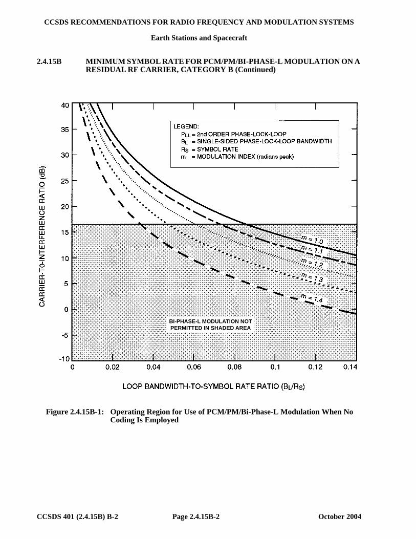
CCSDS RECOMMENDATIONS FOR RADIO FREQUENCY AND MODULATION SYSTEMS
Earth Stations and Spacecraft
CCSDS 401 (2.4.15B) B-2 Page 2.4.15B-2 October 2004
2.4.15B MINIMUM SYMBOL RATE FOR PCM/PM/BI-PHASE-L MODULATION ON A RESIDUAL RF CARRIER, CATEGORY B (Continued)
BI-PHASE-L MODULATION NOTPERMITTED IN SHADED AREA
Figure 2.4.15B-1: Operating Region for Use of PCM/PM/Bi-Phase-L Modulation When No Coding Is Employed

CCSDS RECOMMENDATIONS FOR RADIO FREQUENCY AND MODULATION SYSTEMS
Earth Stations and Spacecraft
CCSDS 401 (2.4.15B) B-2 Page 2.4.15B-3 October 2004
2.4.15B MINIMUM SYMBOL RATE FOR PCM/PM/BI-PHASE-L MODULATION ON A RESIDUAL RF CARRIER, CATEGORY B (Continued)
BI-PHASE-L MODULATION NOTPERMITTED IN SHADED AREA
Figure 2.4.15B-2: Operating Region for Use of PCM/PM/Bi-Phase-L Modulation When CCSDS Concatenated Coding Is Employed

CCSDS RECOMMENDATIONS FOR RADIO FREQUENCY AND MODULATION SYSTEMS
Earth Stations and Spacecraft
CCSDS 401 (2.4.16) B-2 Page 2.4.16-1 October 2004
2.4.16 MAXIMUM PERMISSIBLE SPURIOUS EMISSIONS The CCSDS, considering (a) that spurious emissions (ITU-RR-145) in the form of spectral lines can cause harmful
interference to receiving stations operating in the allocated or adjacent frequency bands; (b) that such spurious emissions are caused by technological imperfections in the transmitting
station, such as asymmetry of the baseband modulating waveform and crosstalk of the operating frequencies on the electronic power conditioners;
(c) that current technology permits reduction of these spectral components to -60 dBc or lower; (d) that protection criteria specified for neighboring radiocommunication services may require
additional reduction of spectral components; (e) that filtering can be applied if further reduction in the level of spectral components is required; recommends
that the total power contained in any single spurious emission shall not exceed -60 dBc.1 NOTE:
1. dBc is measured with respect to the unmodulated carrier level’s total power.

CCSDS RECOMMENDATIONS FOR RADIO FREQUENCY AND MODULATION SYSTEMS
Earth Stations and Spacecraft
CCSDS 401 (2.4.17A) B-2 Page 2.4.17A-1 July 2008
2.4.17A MODULATION METHODS FOR HIGH SYMBOL RATE TRANSMISSIONS, SPACE RESEARCH, SPACE-TO-EARTH, CATEGORY A
The CCSDS, considering (a) that efficient use of RF spectrum resources is imperative with the increasing congestion of the
frequency bands; (b) that the SFCG has approved a Recommendation,1 specifying a spectrum mask for Space
Research Category A Space-to-Earth links operating in certain bands;2 (c) that suppressed carrier modulation techniques, such as GMSK4 and baseband filtered OQPSK5
modulations, can meet the SFCG Recommended1 spectrum mask for symbol rates in excess of 2 Ms/s;
(d) that since GMSK modulation is inherently differential in nature, the use of GMSK with
precoding is necessary to optimize bit error rate performance; (e) that GMSK4 and baseband filtered OQPSK5 modulation types can be demodulated using a
conventional OQPSK receiver, but with differing end-to-end losses; (f) that GMSK4 and baseband filtered OQPSK5 modulations have only a small performance
degradation as compared with ideal unfiltered suppressed carrier systems; (g) that some space agencies currently have no plans to modify their existing OQPSK ground
station receivers to optimize reception of GMSK4 and baseband filtered OQPSK5 signals, so that these two modulation techniques will incur greater losses than unfiltered OQPSK;5
(h) that GMSK and baseband filtered OQPSK modulations have immunity to interference (wideband
and narrow band) comparable to unfiltered BPSK when demodulated with an OQPSK receiver matched to an unfiltered OQPSK waveform; the interference immunity of these modulations when demodulated with matched filter receivers is equivalent to or better than BPSK;
recommends6 that, to comply with the SFCG Recommendation1 and to ensure an ability to obtain cross-
support in certain Space Research service bands2 GMSK4 or baseband filtered OQPSK5 be used for space-to-Earth transmissions when the telemetry data symbol rates exceed 2 Ms/s.
NOTES: 1 See SFCG Recommendation 21-2R2 or latest version. 2 Category A bands are: 2200-2290 MHz and 8450-8500 MHz. 4 Gaussian Minimum Shift Keying (BTS = 0.25), with pre-coding as in figure 2.4.17A-1 (see CCSDS 413.0-G-3). B refers to the
one-sided 3-dB bandwidth of the filter. 5 Filtered (Square Root Raised Cosine = 0.5) Offset QPSK; Butterworth 6 poles, BTS = 0.5; agencies may also utilize filtered
OQPSK modulation with other types of bandpass filters provided that the equivalent baseband BTS is not greater than 0.5 and they ensure compliance with SFCG Recommendation 21-2R2 (or latest version) and interoperability with the cross-supporting networks. B refers to the one-sided 3-dB bandwidth of the filter.
6 Space agencies requiring cross-support should consider the performance degradation of the filtered OQPSK and GMSK modulation techniques when received with unmatched demodulators at existing ground stations (see performance data in CCSDS 413.0-G-3); the ordering of modulation types does not imply a preference.

CCSDS RECOMMENDATIONS FOR RADIO FREQUENCY AND MODULATION SYSTEMS
Earth Stations and Spacecraft
CCSDS 401 (2.4.17A) B-2 Page 2.4.17A-2 July 2008
2.4.17A MODULATION METHODS FOR HIGH SYMBOL RATE TRANSMISSIONS, SPACE RESEARCH, SPACE-TO-EARTH, CATEGORY A (Continued)
Input NRZbit stream
a k
z -1dk
(-1)k
to GMSK modulator
Figure 2.4.17A-1: GMSK Precoder

CCSDS RECOMMENDATIONS FOR RADIO FREQUENCY AND MODULATION SYSTEMS
Earth Stations and Spacecraft
CCSDS 401 (2.4.17B) B-3 Page 2.4.17B-1 July 2008
2.4.17B MODULATION METHODS AT HIGH SYMBOL RATE TRANSMISSIONS, SPACE RESEARCH, SPACE-TO-EARTH, CATEGORY B
The CCSDS, considering (a) that in accordance with ITU RR 3.9, efficient use of the RF spectrum resources is required; (b) that the SFCG has approved an Efficient Spectrum Utilization Recommendation1 which
specifies maximum allowable bandwidth (B25)1 guidelines based on the symbol rate for emissions in the Space Research, Category B, 8 GHz band;
(c) that the maximum bandwidth (B25)1 in the Space Research, Category B, 8 GHz band under the
SFCG Recommendation1 is limited to 12 MHz for non-Mars missions on a non-interfering basis to other missions and 8 MHz in all other cases;
(d) that the Space Research, Category B, frequency allocation at 2 GHz is 10 MHz, requiring high
symbol rate users sharing the band to be spectrally efficient; (e) that 2 Ms/s is used as a boundary for the definition of high symbol rate for Space Research,
Category A, Space-to-Earth transmissions in both the 2 and 8 GHz bands;2 (f) that GMSK3 is a spectrally efficient modulation with negligible end-to-end losses using an
optimized receiver; (g) that since GMSK modulation is inherently differential in nature, the use of GMSK with
precoding is necessary to optimize bit error rate performance; (h) that short periodic data patterns can result in zero power at the carrier frequency; recommends (1) that GMSK3 be used for high data rate transmissions whenever practicable and in any case for rates
in excess of 2 Ms/s in communications systems operating in either the 2 or 8 GHz bands, provided that in no case the transmission bandwidth (B25)1 exceed that recommended by the SFCG;1
(2) that Category B missions requiring transmission bandwidths (B25)1 higher than that recommended4 by the SFCG in 8 GHz band, use the 31.8-32.3 GHz band instead;
(3) that CCSDS agencies use a data randomizer as specified in the CCSDS telemetry
synchronization and channel coding blue book 131.0-B-1 (or latest edition). NOTES: 1 See SFCG Recommendation 23-1 or latest version. 2 See CCSDS Recommendation 401 (2.4.17A) B-1. 3 Gaussian Minimum Shift Keying (BTS = 0.5), with precoding as in figure 2.4.17B-1 (see CCSDS 413.0-G-3). B refers to the one-sided 3-dB bandwidth of the filter. 4 Under the 12 MHz bandwidth limitation for non-Mars missions on a non-interfering basis, the maximum symbol rate using GMSK BTS=0.5 is 9.3 Ms/s. For Mars missions and non-Mars missions which interfere with Mars missions, the maximum symbol rate using GMSK BTS=0.5 is 6.2 Ms/s.

CCSDS RECOMMENDATIONS FOR RADIO FREQUENCY AND MODULATION SYSTEMS
Earth Stations and Spacecraft
CCSDS 401 (2.4.17B) B-3 Page 2.4.17B-2 July 2008
2.4.17B MODULATION METHODS AT HIGH SYMBOL RATE TRANSMISSIONS,
SPACE RESEARCH, SPACE-TO-EARTH, CATEGORY B (Continued)
Input NRZbit stream
a k
z -1dk
(-1)k
to GMSK modulator
Figure 2.4.17B-1: GMSK Precoder

CCSDS RECOMMENDATIONS FOR RADIO FREQUENCY AND MODULATION SYSTEMS
Earth Stations and Spacecraft
CCSDS 401 (2.4.18) B-5 Page 2.4.18-1 October 2017
2.4.18 MODULATION METHODS AT HIGH SYMBOL RATE TRANSMISSIONS, EARTH EXPLORATION SATELLITES (EES) 8 GHZ BAND, SPACE-TO-EARTH
The CCSDS, considering (a) that efficient use of RF spectrum resources is becoming increasingly important with the
increasing congestion of the frequency bands; (b) that the 8025-8400 MHz band is heavily used and interference conflicts may become
increasingly frequent in this band; (c) that the SFCG has approved a Recommendation1 which specifies a spectrum mask for
emissions with symbol rates below and above 2 Ms/s; (d) that the SFCG has approved a Recommendation2 on the use of the 8025-8400 MHz band
recommending that bandwidth- and power-efficient modulation and coding techniques be used; (e) that CCSDS 131.0-B-2, CCSDS 131.2-B-1, and CCSDS 131.3-B-1 foresee a number of coding
schemes, some of which may be incompatible with the bandwidth-efficient use of the 8025-8400 MHz band;
(f) that contiguous to 8400 MHz, a particularly sensitive allocation to Space Research, deep space,
requires adequate protection from unwanted emissions generated by EES;3 (g) that only filtered suppressed carrier systems can meet the bandwidth efficiency of the SFCG
spectrum mask Recommendation for symbol rates in excess of 2 Ms/s and limit unwanted emissions into the neighboring bands;1
(h) that Square Root Raised Cosine (SRRC) filtered 4-Dimensional 8PSK Trellis Coded
Modulation (SRRC-4D 8PSK TCM),4 SRRC-QPSK, SRRC-OQPSK, SRRC-8PSK, SRRC-16APSK, SRRC-32APSK, and SRRC-64APSK,5 and some filtered OQPSK6 modulations spectra can meet the SFCG emission mask for symbol rates in excess of 2 Ms/s with acceptable end-to-end losses;
(j) that baseband filtered QPSK, OQPSK, and 8PSK receivers are readily available in most space
agencies’ ground networks; (j) that baseband filtered receivers for higher order modulations are available through a number of
vendors;
1 See SFCG Recommendation 21-2R4 or latest version. 2 See SFCG Recommendation 14-3R10 or latest version. 3 See SFCG Recommendation 14-1R1 or latest version. 4 Square Root Raised Cosine (α = 0.35 and α = 0.5) 4D 8PSK Trellis Coded Modulation (see Annex 1). 5 Square Root Raised Cosine with α = 0.2, 0.25, 0.3, and 0.35 (see Annex 2). 6 Filtered (Square Root Raised Cosine α = 0.5) Offset QPSK; Butterworth 6 poles, BTS = 0.5; agencies may also utilize filtered OQPSK modulation with other types of bandpass filters provided that the equivalent baseband BTS is not greater than 0.5 and they ensure compliance with SFCG Recommendation 21-2R4 (or latest version) and interoperability with the cross-supporting networks. B refers to the one-sided 3-dB bandwidth of the filter.

CCSDS RECOMMENDATIONS FOR RADIO FREQUENCY AND MODULATION SYSTEMS
Earth Stations and Spacecraft
CCSDS 401 (2.4.18) B-5 Page 2.4.18-2 October 2017
2.4.18 MODULATION METHODS AT HIGH SYMBOL RATE TRANSMISSIONS, EARTH EXPLORATION SATELLITES (EES) 8 GHZ BAND, SPACE-TO-EARTH (Continued)
(k) that a phase imbalance of less than 3 degrees and an amplitude imbalance of less than 0.5 dB
should result in acceptable performance degradations; l) that a channel with in-band ripple up to 0.1 dB, out-of-band rejection of at least 30 dB, and in-
band (within channel symbol rate) group-delay variations up to 10 percent of the signal duration7 should result in acceptable performance degradations even in case no equalization is used at the receiver;
noting (1) that filtered OQPSK signals can also be demodulated by unfiltered OQPSK receivers with
some mismatching losses;8 (2) that many missions are currently operating in this band with a signaling efficiency9 over 1.75
source bits/channel symbol;
(3) that recommended maximum values of phase noise and HPA linearity are needed to ensure small end-to-end losses;
(4) that linearization techniques (pre‐distortion) or compensation (equalization, centroid tuning) or
both can reduce the channel losses, especially for APSK modulations; (5) that the use of a frame header and of pilot symbols can improve the acquisition time as well as
tracking performance;
(6) that the constellation bit mapping for SRRC-4D 8PSK TCM10 is natural, while constellation bit mappings for SRRC-8PSK, SRRC-16APSK, SRRC-32APSK, and SRRC-64APSK are Gray coded and are different in CCSDS 131.2-B-1 and CCSDS 131.3-B-1;
recommends (1) that a mission planning to operate in the 8025-8400 MHz band shall use SRRC-4D 8PSK
TCM10 or SRRC-QPSK, SRRC-OQPSK, SRRC-8PSK, SRRC-16APSK, SRRC-32APSK, and SRRC-64APSK11 or filtered OQPSK;12
7 1 ns at 100 Ms/s (channel symbol rate). 8 See annex B4 of CCSDS 413.0-G-2 for SRRC and Butterworth filtered OQPSK mismatching losses. 9 Ratio of source data rate to channel symbol rate. 10 Available options are 2.0 b/s/Hz, 2.25 b/s/Hz, 2.5 b/s/Hz, and 2.75 b/s/Hz; Square Root Raised Cosine filter with α = 0.35 or α = 0.5 (see Annex 1). 11 Square Root Raised Cosine filter with α = 0.2, 0.25, 0.3, and 0.35 (see Annex 2). 12 Filtered (Square Root Raised Cosine α = 0.5) Offset QPSK; baseband Butterworth 6 poles, BTS = 0.5; agencies may also utilize filtered OQPSK modulation with other types of bandpass filters provided that the equivalent baseband BTS is not greater than 0.5 and they ensure compliance with SFCG Recommendation 21-2R4 (or latest version) and interoperability with the cross-supporting networks. B refers to the one-sided 3-dB bandwidth of the filter.

CCSDS RECOMMENDATIONS FOR RADIO FREQUENCY AND MODULATION SYSTEMS
Earth Stations and Spacecraft
CCSDS 401 (2.4.18) B-5 Page 2.4.18-3 October 2017
2.4.18 MODULATION METHODS AT HIGH SYMBOL RATE TRANSMISSIONS, EARTH EXPLORATION SATELLITES (EES) 8 GHZ BAND, SPACE-TO-EARTH (Continued)
(2) that a mission planning to use this band should select the most bandwidth-efficient channel
coding scheme from CCSDS 131.0-B-2 or 131.2-B-1 or 131.3-B-1 compatible with the mission constraints;
(3) that Variable Coding and Modulation (VCM) or Adaptive Coding and Modulation (ACM) techniques should be used where practicable;13
(4) that linearization techniques (pre‐distortion) at the transmitter or compensation (such as equalization or centroid tuning) at the receiver should be used to minimize the end-to-end losses at least for 16APSK and higher-order modulations, and in any case if the channel is worse than in considering (k);
(5) that a frame header (see A2.5) and pilot symbols14 should be used to improve the acquisition and tracking performance especially for modulations with order higher than 8PSK;
(6) that the phase noise of the communication chain should be limited according to the mask given
in Annex 1 or Annex 2 depending on the selected scheme;15 (7) that the modulator’s phase imbalance shall not exceed 5 degrees for SRRC-QPSK, SRRC-
OQPSK, SRRC-4D 8PSK TCM, SRRC-8PSK, and SRRC-16APSK and 3 degrees for SRRC-32APSK and SRRC-64APSK, and the amplitude imbalance shall not exceed 0.5 dB between the constellation points;
(8) that the AM/PM slope for the non-linear amplifier shall be less than 5°/dB unless appropriate
equalization at the receiver is performed.
13 Relative Recommended Practices (Magenta Books) are under preparation. 14 For systems compliant with CCSDS 131.2-B-1 and CCSDS 131.3-B-1, the relevant standard should be consulted. For systems compliant with CCSDS 131.0-B-2 further work is needed. 15 For filtered OQPSK,12 Annex 2 applies.

CCSDS RECOMMENDATIONS FOR RADIO FREQUENCY AND MODULATION SYSTEMS
Earth Stations and Spacecraft
CCSDS 401 (2.4.18) B-5 Page 2.4.18-4 October 2017
2.4.18 MODULATION METHODS AT HIGH SYMBOL RATE TRANSMISSIONS, EARTH EXPLORATION SATELLITES (EES) 8 GHZ BAND, SPACE-TO-EARTH (Continued)
ANNEX 1
4-Dimensional 8PSK Trellis Coded Modulation Definition
(Normative)
A1.1 GENERAL The 4D-8PSK trellis-coded modulator consists of a serial-to-parallel converter, a differential coder, a trellis encoder (convolutional coder), a constellation mapper, and an 8PSK modulator (see figure 2.4.18-1). It should be noted that in this figure, ‘wi’ (with index i = 1, … , m) represent the uncoded bits and ‘xj’ (with index j = 0, … , m) are the coded bits. The trellis encoder is based on a 64-state systematic convolutional coder and can be considered as the inner code if an outer block code is introduced. Carrier phase ambiguity is resolved by the use of a differential coder located prior to the trellis encoder. Spectral efficiencies of 2, 2.25, 2.5, and 2.75 bits/channel-symbol are achieved with four possible architectures of the constellation mapper. The output switch addresses successively one of the four symbols ( Z(0) – Z(3) ) from the constellation mapper to the 8PSK modulator. The present standard is based on the following parameters:
– size of the constellation: M=8 phase states (8PSK); – number of signal set constituents: L=4 (shown as Z(0) … Z(3) in figure 2.4.18-1); – number of states for the trellis encoder: 64; – rate of the convolutional coder used for the construction of the trellis: R=3/4; – rate of the modulation: Rm=m/(m+1) selectable to 8/9, 9/10, 10/11, or 11/12; – efficiency of the modulation:
• Reff=2 bits per channel-symbol (for Rm=8/9); • Reff=2.25 bits per channel-symbol (for Rm=9/10); • Reff=2.5 bits per channel-symbol (for Rm=10/11); • Reff=2.75 bits per channel-symbol (for Rm=11/12).
Seria
l to
Para
llel c
onve
rsio
n
Con
stel
latio
n m
appe
r
wi
ConvolutionalCoder R=3/4
xj (j above 3)
x3x2x1
x0 CarrierGenerator
ModulatedCarrier
Dat
a In
Diff
eren
tialc
oder
Z(0)
Z(1)
Z(2)
Z(3)
Seria
l to
Para
llel c
onve
rsio
n
Con
stel
latio
n m
appe
r
wi
ConvolutionalCoder R=3/4ConvolutionalCoder R=3/4
xj (j above 3)
x3x2x1
x0 CarrierGenerator
ModulatedCarrier
Dat
a In
Diff
eren
tialc
oder
Z(0)
Z(1)
Z(2)
Z(3)
Z(0)
Z(1)
Z(2)
Z(3)
Figure 2.4.18-1: Structure of the 4D 8PSK-TCM Coder/Mapper

CCSDS RECOMMENDATIONS FOR RADIO FREQUENCY AND MODULATION SYSTEMS
Earth Stations and Spacecraft
CCSDS 401 (2.4.18) B-5 Page 2.4.18-5 October 2017
2.4.18 MODULATION METHODS AT HIGH SYMBOL RATE TRANSMISSIONS, EARTH EXPLORATION SATELLITES (EES) 8 GHZ BAND, SPACE-TO-EARTH (Continued)
ANNEX 1 (Continued)
A1.2 DIFFERENTIAL CODER The differential coder is depicted in figure 2.4.18-2. Table 2.4.18-1 gives the bit reference at input and output of the differential coder in each case.
Table 2.4.18-1: Bit Mapping for Differential Coder with Modulo-8 Addition
Efficiencies in bits /channel-symbol 2 2.25 2.5 2.75
bit IN bit OUT bit IN bit OUT bit IN bit OUT bit IN bit OUT w1 x1 w2 x2 w3 x3 w4 x4 w5 x5 w6 x6 w7 x7 w8 x8 w8 x8 w9 x9 w10 x10 w11 x11
An example of differential encoder connections is given in figure 2.4.18-2 for the 2 bits/channel-symbol case. The structure of the modulo-8 adder is also shown; it is applicable to both the coder mapper and differential coder.
+2 1 0 2 1 0
2 1 0
w8w5w1
x8 x5 x1
b8 b5 b1
D
IN
OUT
a2 a1 a0b2 b1b0
c2 c1c0
+2 01 2 01
2 01
c0 = a0 b0 with carry r0 c1 = a1 b1 r0 with carry r1 c2 = a2 b2 r1 r0 = a0.b0 r1 = (a1.b1)+(a1.r0)+(b1.r0) where . corresponds to a logical AND, and + to a logical OR
Figure 2.4.18-2: Differential Coder and Modulo-8 Adder Principle

CCSDS RECOMMENDATIONS FOR RADIO FREQUENCY AND MODULATION SYSTEMS
Earth Stations and Spacecraft
CCSDS 401 (2.4.18) B-5 Page 2.4.18-6 October 2017
2.4.18 MODULATION METHODS AT HIGH SYMBOL RATE TRANSMISSIONS, EARTH EXPLORATION SATELLITES (EES) 8 GHZ BAND, SPACE-TO-EARTH (Continued)
ANNEX 1 (Continued)
A1.3 CONVOLUTIONAL CODER The convolutional coder used to implement the trellis is depicted in figure 2.4.18-3. The shift registers of the encoder are clocked at the rate of RChS/4.
D
IN
OU T
x0
x1x2x3
x1
x3x2
D D D D D
Figure 2.4.18-3: Convolutional Coder Recommended for High Data Rates
A1.4 CONSTELLATION MAPPER FOR 4D-8PSK-TCM The constellation mapper principles are given in figures 2.4.18-4 to 2.4.18-7 for the four possible efficiencies of this modulation (i.e., 2 bits/channel-symbol, 2.25 bits/channel-symbol, 2.5 bits/channel-symbol, and 2.75 bits/channel-symbol). These mappers implement the straightforward logical mapping described in the figures below. The correspondence between the signals Z (i) at the input of the modular and the 8PSK phase states of the constellations follows a natural mapping (i.e., 0, 1, 2 …, 7 anticlockwise).
x0x1x2x3x4x5x6x7x8
Z 1,2
Z 1,1Z 1,0
0
+
+
+ +
2 1 0
2 1 0 2 1 0 2 1 0 2 1 0 2 1 0 2 1 0
2 1 0
2 1 0
2 1 0 2 1 0 2 1 0
0 0
0
Z (1)
Z (1)
Z (1)
2 1 0 Z (2)
Z (2)
Z (2)
2 1 0Z
(0)Z
(0)Z
(0)
2 1 0 Z (3)
Z (3)
Z (3)
2 1 0
x0x1x2x3x4x5x6x7x8
Z 1,2
Z 1,1Z 1,0
0
+
+
+ +
2 1 0
2 1 0 2 1 0 2 1 0 2 1 0 2 1 0 2 1 0
2 1 0
2 1 0
2 1 0 2 1 0 2 1 0
0 0
0
Z (1)
Z (1)
Z (1)
2 1 0 Z (2)
Z (2)
Z (2)
2 1 0Z
(0)Z
(0)Z
(0)
2 1 0 Z (3)
Z (3)
Z (3)
2 1 0
= line connected to differential coder = line connected to serial-to-parallel converter or convolutional coder
Figure 2.4.18-4: Constellation Mapper for 2 Bits/Channel-Symbol

CCSDS RECOMMENDATIONS FOR RADIO FREQUENCY AND MODULATION SYSTEMS
Earth Stations and Spacecraft
CCSDS 401 (2.4.18) B-5 Page 2.4.18-7 October 2017
2.4.18 MODULATION METHODS AT HIGH SYMBOL RATE TRANSMISSIONS, EARTH EXPLORATION SATELLITES (EES) 8 GHZ BAND, SPACE-TO-EARTH (Continued)
ANNEX 1 (Continued)
x0x1x2x3x4x5x6x7x8x9
0
+
+
2 1 0
2 1 0 2 1 0
2 1 0
2 1 0
+2 1 0 2 1 0
2 1 0 +2 1 0 2 1 0
2 1 02 1 0
0
0
Z (1)
Z (1)
Z (1)
2 1 0 Z (2)
Z (2)
Z (2)
2 1 0Z
(0)Z
(0)Z
(0)
2 1 0Z
(3)Z
(3)Z
(3)2 1 0
Z (1)
Z (1)
Z (1)
2 1 0
x0x1x2x3x4x5x6x7x8x9
0
+
+
2 1 0
2 1 0 2 1 0
2 1 0
2 1 0
+2 1 0 2 1 0
2 1 0 +2 1 0 2 1 0
2 1 02 1 0
0
0
Z (1)
Z (1)
Z (1)
2 1 0 Z (2)
Z (2)
Z (2)
2 1 0Z
(0)Z
(0)Z
(0)
2 1 0Z
(3)Z
(3)Z
(3)2 1 0
Z (1)
Z (1)
Z (1)
2 1 0
= line connected to differential coder = line connected to serial-to-parallel converter or convolutional coder
Figure 2.4.18-5: Constellation Mapper for 2.25 Bits/Channel-Symbol
x0x1x2x3x4x5x6x7x8x9x10
0
+
+
+ +
2 1 0
2 1 0 2 1 0 2 1 0 2 1 0 2 1 0 2 1 0
2 1 0
2 1 0
2 1 0 2 1 0 2 1 0
Z (0)
Z (0)
Z (0)
2 1 0 Z (1)
Z (1)
Z (1)
2 1 0 Z (2)
Z (2)
Z (2)
2 1 0 Z (3)
Z (3)
Z (3)
2 1 0
Z (1)
Z (1)
Z (1)
2 1 0
x0x1x2x3x4x5x6x7x8x9x10
0
+
+
+ +
2 1 0
2 1 0 2 1 0 2 1 0 2 1 0 2 1 0 2 1 0
2 1 0
2 1 0
2 1 0 2 1 0 2 1 0
Z (0)
Z (0)
Z (0)
2 1 0 Z (1)
Z (1)
Z (1)
2 1 0 Z (2)
Z (2)
Z (2)
2 1 0 Z (3)
Z (3)
Z (3)
2 1 0
Z (1)
Z (1)
Z (1)
2 1 0
= line connected to differential coder = line connected to serial-to-parallel converter or convolutional coder
Figure 2.4.18-6: Constellation Mapper for 2.5 Bits/Channel-Symbol

CCSDS RECOMMENDATIONS FOR RADIO FREQUENCY AND MODULATION SYSTEMS
Earth Stations and Spacecraft
CCSDS 401 (2.4.18) B-5 Page 2.4.18-8 October 2017
2.4.18 MODULATION METHODS AT HIGH SYMBOL RATE TRANSMISSIONS, EARTH EXPLORATION SATELLITES (EES) 8 GHZ BAND, SPACE-TO-EARTH (Continued)
ANNEX 1 (Continued)
x0x1x2x3x4x5x6x7x8x9x10x11
Z (1)
Z (1)
Z (1)
+
+ +
2 1 0
2 1 0 2 1 0 2 1 0 2 1 0 2 1 0 2 1 0
2 1 0
2 1 0
2 1 0
2 1 0 Z (2)
Z (2)
Z (2)
2 1 0Z
(0)Z
(0)Z
(0)2 1 0 Z
(3)Z
(3)Z
(3)
2 1 0
Z (1)
Z (1)
Z (1)
2 1 0
2 1 0+
2 1 0
x0x1x2x3x4x5x6x7x8x9x10x11
Z (1)
Z (1)
Z (1)
+
+ +
2 1 0
2 1 0 2 1 0 2 1 0 2 1 0 2 1 0 2 1 0
2 1 0
2 1 0
2 1 0
2 1 0 Z (2)
Z (2)
Z (2)
2 1 0Z
(0)Z
(0)Z
(0)2 1 0 Z
(3)Z
(3)Z
(3)
2 1 0
Z (1)
Z (1)
Z (1)
2 1 0
2 1 0+
2 1 0
= line connected to differential coder = line connected to serial to parallel converter or convolutional coder
Figure 2.4.18-7: Constellation Mapper for 2.75 Bits/Channel-Symbol

CCSDS RECOMMENDATIONS FOR RADIO FREQUENCY AND MODULATION SYSTEMS
Earth Stations and Spacecraft
CCSDS 401 (2.4.18) B-5 Page 2.4.18-9 October 2017
2.4.18 MODULATION METHODS AT HIGH SYMBOL RATE TRANSMISSIONS, EARTH EXPLORATION SATELLITES (EES) 8 GHZ BAND, SPACE-TO-EARTH (Continued)
ANNEX 1 (Continued)
A1.5 CODER/MAPPER IMPLEMENTATION AT 2, 2.25, 2.5, AND 2.75
BITS/CHANNEL-SYMBOL EFFICIENCY The principle of the coder-mapper for 2, 2.25, 2.5, and 2.75 bits/channel-symbol efficiency is given in figures 2.4.18-8 through 2.4.18-11.
Seria
l to
Para
llel c
onve
rsio
n
Differentialcoder
Cons
tella
tion
map
per
w8x7x6w5x4x3x2w1
ConvolutionalCoder R=3/4
x8x7x6x5x4x3x2x1
x0
CarrierGenerator
ModulatedCarrier
Dat
a In
Z(0)
Z(1)
Z(2)
Z(3)
Seria
l to
Para
llel c
onve
rsio
n
Differentialcoder
Cons
tella
tion
map
per
w8x7x6w5x4x3x2w1
ConvolutionalCoder R=3/4
x8x7x6x5x4x3x2x1
x0
CarrierGenerator
ModulatedCarrier
Dat
a In
Z(0)
Z(1)
Z(2)
Z(3)
Z(0)
Z(1)
Z(2)
Z(3)
Figure 2.4.18-8: Coder and Mapper Implementation for 2 Bits/Channel-Symbol Efficiency
Seria
l to
Para
llel c
onve
rsio
n
Differentialcoder
Con
stel
latio
n m
appe
rw9x8x7w6x5x4x3w2x1
ConvolutionalCoder R=3/4
x9x8x7x6x5x4x3x2x1
x0 CarrierGenerator
ModulatedCarrier
Dat
a In
Z(0)
Z(1)
Z(2)
Z(3)
Seria
l to
Para
llel c
onve
rsio
n
Differentialcoder
Con
stel
latio
n m
appe
rw9x8x7w6x5x4x3w2x1
ConvolutionalCoder R=3/4ConvolutionalCoder R=3/4
x9x8x7x6x5x4x3x2x1
x0 CarrierGenerator
ModulatedCarrier
Dat
a In
Z(0)
Z(1)
Z(2)
Z(3)
Z(0)
Z(1)
Z(2)
Z(3)
Figure 2.4.18-9: Coder and Mapper Implementation at 2.25 Bits/Channel-Symbol Efficiency

CCSDS RECOMMENDATIONS FOR RADIO FREQUENCY AND MODULATION SYSTEMS
Earth Stations and Spacecraft
CCSDS 401 (2.4.18) B-5 Page 2.4.18-10 October 2017
2.4.18 MODULATION METHODS AT HIGH SYMBOL RATE TRANSMISSIONS, EARTH EXPLORATION SATELLITES (EES) 8 GHZ BAND, SPACE-TO-EARTH (Continued)
ANNEX 1 (Continued)
Seria
l to
Para
llel c
onve
rsio
n
Differentialcoder
Cons
tella
tion
map
per
w10x9x8w7x6x5x4w3x2x1
ConvolutionalCoder R=3/4
x10x9x8x7x6x5x4x3x2x1
x0 CarrierGenerator
ModulatedCarrier
Dat
a In
Z(0)
Z(1)
Z(2)
Z(3)
Seria
l to
Para
llel c
onve
rsio
n
Differentialcoder
Cons
tella
tion
map
per
w10x9x8w7x6x5x4w3x2x1
ConvolutionalCoder R=3/4ConvolutionalCoder R=3/4
x10x9x8x7x6x5x4x3x2x1
x0 CarrierGenerator
ModulatedCarrier
Dat
a In
Z(0)
Z(1)
Z(2)
Z(3)
Z(0)
Z(1)
Z(2)
Z(3)
Figure 2.4.18-10: Coder and Mapper Implementation at 2.5 Bits/Channel-Symbol Efficiency
Seria
l to
Para
llel c
onve
rsio
n
Differentialcoder
Con
stel
latio
n m
appe
r
x10x9w8x7x6x5w4x3x2x1
ConvolutionalCoder R=3/4
x10x9x8x7x6x5x4x3x2x1
x0 CarrierGenerator
ModulatedCarrier
Dat
a In
w11 x11 Z(0)
Z(1)
Z(2)
Z(3)
Seria
l to
Para
llel c
onve
rsio
n
Differentialcoder
Con
stel
latio
n m
appe
r
x10x9w8x7x6x5w4x3x2x1
ConvolutionalCoder R=3/4ConvolutionalCoder R=3/4
x10x9x8x7x6x5x4x3x2x1
x0 CarrierGenerator
ModulatedCarrier
Dat
a In
w11 x11 Z(0)
Z(1)
Z(2)
Z(3)
Z(0)
Z(1)
Z(2)
Z(3)
Figure 2.4.18-11: Coder and Mapper Implementation at 2.75 Bits/Channel-Symbol Efficiency

CCSDS RECOMMENDATIONS FOR RADIO FREQUENCY AND MODULATION SYSTEMS
Earth Stations and Spacecraft
CCSDS 401 (2.4.18) B-5 Page 2.4.18-11 October 2017
2.4.18 MODULATION METHODS AT HIGH SYMBOL RATE TRANSMISSIONS, EARTH EXPLORATION SATELLITES (EES) 8 GHZ BAND, SPACE-TO-EARTH (Continued)
ANNEX 1 (Continued)
A1.6 SRRC CHANNEL FILTERING The normalized transfer function of the SRRC filter shall be:16,17
( ) ( )
( ) ( ) ( )
( )
1 if 1
1 1 sin if 1 12 2 2
0
N
NN N
N
H f f f
f fH f f f f
f
H f
α
π α αα
= < −
⎧ ⎫⎛ ⎞−⎪ ⎪= + − ≤ ≤ +⎨ ⎬⎜ ⎟⎪ ⎪⎝ ⎠⎩ ⎭
= ( )if 1Nf f α> +
where 1/(2 ) / 2N chs chsf T R= = is the Nyquist frequency and α is the roll-off factor. The specified values for the roll-off factor are α = 0.35 and 0.5.
A1.7 PHASE NOISE The phase noise for all the oscillators of the communication chain shall be limited according to the mask given in figure 2.4.18-12 for channel symbol rates above 1 Ms/s.
NOTE – The figure shows the double sided phase noise mask 2L(f) in dBc/Hz versus frequency in Hz.
16 SRRC filtering can be practically implemented either with baseband filters or with RF post-amplifier filters, each able to fulfill SFCG Recommendation 21-2R4 (see CCSDS 413.0-G-1). 17 This formulation yields an impulse-response function with dimensions of Hz (or 1/s). Sometimes in literature the transfer function is shown with a multiplication factor chsT in front.

CCSDS RECOMMENDATIONS FOR RADIO FREQUENCY AND MODULATION SYSTEMS
Earth Stations and Spacecraft
CCSDS 401 (2.4.18) B-5 Page 2.4.18-12 October 2017
2.4.18 MODULATION METHODS AT HIGH SYMBOL RATE TRANSMISSIONS, EARTH EXPLORATION SATELLITES (EES) 8 GHZ BAND, SPACE-TO-EARTH (Continued)
ANNEX 1 (Continued)
-130
-120
-110
-100
-90
-80
-70
-60
-50
-40
-30
-20
1.00E+01 1.00E+02 1.00E+03 1.00E+04 1.00E+05 1.00E+06 1.00E+07 1.00E+08 1.00E+09
2L(f
)in
dBc/
Hz
f in Hz
Phase noise mask
Figure 2.4.18-12: 8PSK Phase Noise Mask Recommendation

CCSDS RECOMMENDATIONS FOR RADIO FREQUENCY AND MODULATION SYSTEMS
Earth Stations and Spacecraft
CCSDS 401 (2.4.18) B-5 Page 2.4.18-13 October 2017
2.4.18 MODULATION METHODS AT HIGH SYMBOL RATE TRANSMISSIONS, EARTH EXPLORATION SATELLITES (EES) 8 GHZ BAND, SPACE-TO-EARTH (Continued)
ANNEX 1 (Continued)
A1.8 BIT MAPPING TO CONSTELLATION The following convention is used to identify each bit in an N-bit field. The first bit in the field to be transmitted (i.e., the most left justified when drawing a figure) is defined to be ‘Bit 0’, the following bit is defined to be ‘Bit 1’, and so on up to ‘Bit N−1’. When the field is used to express a binary value (such as a counter), the Most Significant Bit (MSB) shall be the first transmitted bit of the field, i.e., ‘Bit 0’ (see figure 2.4.18-13).
N-Bit Data Field
Bit 0 Bit N-1
First Bit Transmitted = MSB
I
Figure 2.4.18-13: Bit Numbering Convention For instance, bits 3i, 3i+1, 3i+2 of the modulator input determine the ith 8PSK symbol, where i = 0, 1, 2,… (N/3)−1 and N is the block size to be transmitted. The modulation shall employ a natural mapping constellation (i.e., 0, 1, 2, …, 7 anticlockwise) as in figure 2.4.18-14 with associated bit numbering convention as in figure 2.4.18-13. Z(i) represents the signals (three lines) at the input of the modulator, with Z(0) being the signal set of the first constellation and Z(3) being the signal set of the fourth constellation.
Phase state Phase angle (°) Z(i) A 0 000 B 45 001 C 90 010 D 135 011 E 180 100 F 225 101 G 270 110 H 315 111
Figure 2.4.18-14: 4D-8PSK-TCM Symbol Mapping into Constellation

CCSDS RECOMMENDATIONS FOR RADIO FREQUENCY AND MODULATION SYSTEMS
Earth Stations and Spacecraft
CCSDS 401 (2.4.18) B-5 Page 2.4.18-14 October 2017
2.4.18 MODULATION METHODS AT HIGH SYMBOL RATE TRANSMISSIONS, EARTH EXPLORATION SATELLITES (EES) 8 GHZ BAND, SPACE-TO-EARTH (Continued)
ANNEX 2
QPSK/OQPSK/8PSK/16APSK/32APSK/64APSK Modulation Definition
(Normative)
A2.1 GENERAL
The modulation formats here specified shall follow the template provided in table 2.4.18-2, with the relevant parameters that define each constellation. For multi-circle constellations, and in particular for 16- and 32-APSK, different values are provided for the ratio of outer to inner circle radius, optimized based on the code rate used in CCSDS 131.2-B-1 and CCSDS 131.3-B-1.
Table 2.4.18-2: Modulation Definition
Item QPSK and
OQPSK 8PSK 16APSK 32APSK 64APSK
Number of constellation concentric circumferences
1 1 2 3 4
Number of uniformly spaced points per circumference
N1=4 N1=8 N1=4, N2=12 N1=4, N2=12, N3=16
N1=4, N2=12, N3=20, N4=28
Ratio of outer circle to inner circle radius
N.A. N.A. γ1=R2/R1 as per CCSDS 131.2-B-1 and CCSDS 131.3-B-1 (See also 18)
γ1=R2/R1 and γ2=R3/R1 as per CCSDS 131.2-B-1 and CCSDS 131.3-B-1 (See also 19)
γ1=R2/R1 = 2.73, γ2=R3/R1= 4.52, γ3=R4/R1= 6.31
Radii relation for unit average symbol level (average symbol energy =1)
N.A. N.A. [R1]2+3[R2]
2=4 [R1]2+3[R2]
2
+4[R3]2=8
[R1]2+3[R2]
2
+5[R3]2+7[R4]
2
=16
Bit-to-symbol mapping Bits 2i (MSB) and 2i+1 (LSB) determine the ith QPSK symbol
Bits 3i (MSB), 3i+1 and 3i+2 (LSB) determine the ith 8PSK symbol
Bits 4i (MSB), 4i+1, 4i+2 and 4i+3 (LSB) determine the ith
16APSK symbol
Bits 5i (MSB), 5i+1, 5i+2, 5i+3 and 5i+4 (LSB) determine the ith 32APSK symbol
Bits 6i (MSB), 6i+1, 6i+2, 6i+3, 6i+4 and 6i+5 (LSB) determine the ith 64APSK symbol
Constellation proper (See figure 2.4.18-17)
(See figures 2.4.18-18 and 2.4.18-19)
(See figure 2.4.18-20)
(See figure 2.4.18-21)
(See figure 2.4.18-22)
18 For a multistandard system, the range to be covered for γ1 varies from 2.57 to 3.15. 19 For a multistandard system, the range to be covered for γ1 varies from 2.53 to 2.84 and the range for γ2 varies from 4.30 to 5.27.

CCSDS RECOMMENDATIONS FOR RADIO FREQUENCY AND MODULATION SYSTEMS
Earth Stations and Spacecraft
CCSDS 401 (2.4.18) B-5 Page 2.4.18-15 October 2017
2.4.18 MODULATION METHODS AT HIGH SYMBOL RATE TRANSMISSIONS, EARTH EXPLORATION SATELLITES (EES) 8 GHZ BAND, SPACE-TO-EARTH (Continued)
ANNEX 2 (Continued)
A2.2 SRRC CHANNEL FILTERING The transfer function of the SRRC filter shall be:20,21
( ) ( )
( ) ( ) ( )
( )
1 if 1
1 1 sin if 1 12 2 2
0
N
NN N
N
H f f f
f fH f f f f
f
H f
α
π α αα
= < −
⎧ ⎫⎛ ⎞−⎪ ⎪= + − ≤ ≤ +⎨ ⎬⎜ ⎟⎪ ⎪⎝ ⎠⎩ ⎭
= ( )if 1Nf f α> +
where 1/(2 ) / 2N chs chsf T R= = is the Nyquist frequency and α is the roll-off factor. The specified values for the roll-off factor are α = 0.2, 0.25, 0.3, and 0.35.
A2.3 PHASE NOISE The phase noise for all the oscillators of the communication chain shall be limited according to the mask given in figure 2.4.18-15 for channel symbol rates above 1 Ms/s.
NOTE – The figure shows the double-sided phase noise mask 2L(f) in dBc/Hz versus frequency in Hz.
20 SRRC filtering can be practically implemented with baseband filters able to fulfill SFCG Recommendation 21-2R4 (see CCSDS 413.0-G-2). 21 This formulation yields an impulse response function with dimensions of Hz (or 1/s). Sometimes in literature the transfer function is shown with a multiplication factor chsT in front.

CCSDS RECOMMENDATIONS FOR RADIO FREQUENCY AND MODULATION SYSTEMS
Earth Stations and Spacecraft
CCSDS 401 (2.4.18) B-5 Page 2.4.18-16 October 2017
2.4.18 MODULATION METHODS AT HIGH SYMBOL RATE TRANSMISSIONS, EARTH EXPLORATION SATELLITES (EES) 8 GHZ BAND, SPACE-TO-EARTH (Continued)
ANNEX 2 (Continued)
‐130
‐120
‐110
‐100
‐90
‐80
‐70
‐60
‐50
‐40
‐30
‐20
1.00E+01 1.00E+02 1.00E+03 1.00E+04 1.00E+05 1.00E+06 1.00E+07 1.00E+08 1.00E+09
2L(f) in
dBc/H
z
f in Hz
Phase noise mask
Figure 2.4.18-15: Phase Noise Mask Recommendation

CCSDS RECOMMENDATIONS FOR RADIO FREQUENCY AND MODULATION SYSTEMS
Earth Stations and Spacecraft
CCSDS 401 (2.4.18) B-5 Page 2.4.18-17 October 2017
2.4.18 MODULATION METHODS AT HIGH SYMBOL RATE TRANSMISSIONS, EARTH EXPLORATION SATELLITES (EES) 8 GHZ BAND, SPACE-TO-EARTH (Continued)
ANNEX 2 (Continued)
A2.4 BIT MAPPING TO CONSTELLATION The following convention is used to identify each bit in an N-bit field. The first bit in the field to be transmitted (i.e., the most left justified when drawing a figure) is defined to be ‘Bit 0’, the following bit is defined to be ‘Bit 1’, and so on up to ‘Bit N−1’. When the field is used to express a binary value (such as a counter), the Most Significant Bit (MSB) shall be the first transmitted bit of the field, i.e., ‘Bit 0’ (see figure 2.4.18-16).
N-Bit Data Field
Bit 0 Bit N-1
First Bit Transmitted = MSB
I
Figure 2.4.18-16: Bit Numbering Convention For instance, bits 3i, 3i+1, 3i+2 of the modulator input determine the ith 8PSK symbol, where i = 0, 1, 2,…, (N/3)−1, and N is the block size to be transmitted.

CCSDS RECOMMENDATIONS FOR RADIO FREQUENCY AND MODULATION SYSTEMS
Earth Stations and Spacecraft
CCSDS 401 (2.4.18) B-5 Page 2.4.18-18 October 2017
2.4.18 MODULATION METHODS AT HIGH SYMBOL RATE TRANSMISSIONS, EARTH EXPLORATION SATELLITES (EES) 8 GHZ BAND, SPACE-TO-EARTH (Continued)
ANNEX 2 (Continued)
A2.4.1 QPSK and OQPSK Modulations with coding in accordance with CCSDS 131.0-B-2, 131.2-B-1, or CCSDS 131.3-B-1 shall employ a conventional Gray-coded constellation22 with absolute mapping (no differential coding) as in figure 2.4.18-17 with associated bit numbering convention as in figure 2.4.18-16.
I
Q
00
0111
10
I=MSB Q=LSB
Figure 2.4.18-17: QPSK and OQPSK Symbol Mapping into Constellation
22 The mapping is the same as in recommendation 2.4.10.

CCSDS RECOMMENDATIONS FOR RADIO FREQUENCY AND MODULATION SYSTEMS
Earth Stations and Spacecraft
CCSDS 401 (2.4.18) B-5 Page 2.4.18-19 October 2017
2.4.18 MODULATION METHODS AT HIGH SYMBOL RATE TRANSMISSIONS, EARTH EXPLORATION SATELLITES (EES) 8 GHZ BAND, SPACE-TO-EARTH (Continued)
ANNEX 2 (Continued)
A2.4.2 8PSK Modulations with coding in accordance with CCSDS 131.0-B-2,131.2-B-1, or CCSDS 131.3-B-1 shall employ a conventional Gray-coded constellation with absolute mapping (no differential coding) as respectively in figures 2.4.18-18 and 2.4.18-19 with associated bit numbering convention as in figure 2.4.18-16.
Figure 2.4.18-18: 8PSK Symbol Mapping into Constellation (CCSDS 131.0-B-2 and 131.2-B-1)
Figure 2.4.18-19: 8PSK Symbol Mapping into Constellation (CCSDS 131.3-B-1)

CCSDS RECOMMENDATIONS FOR RADIO FREQUENCY AND MODULATION SYSTEMS
Earth Stations and Spacecraft
CCSDS 401 (2.4.18) B-5 Page 2.4.18-20 October 2017
2.4.18 MODULATION METHODS AT HIGH SYMBOL RATE TRANSMISSIONS, EARTH EXPLORATION SATELLITES (EES) 8 GHZ BAND, SPACE-TO-EARTH (Continued)
ANNEX 2 (Continued)
A2.4.3 16APSK Modulations with coding in accordance with CCSDS 131.0-B-2 or 131.2-B-1, and CCSDS 131.3-B-1 shall employ a conventional Gray-coded constellation with absolute mapping (no differential coding) as in figure 2.4.18-20 and with associated bit numbering convention as in figure 2.4.18-16.
0011
10111111
0111
0000
0010
1010
1000
10011101
1100
1110
0110
0100
0101 0001
Q
R1
16 APSK
I
MSB LSB
R2
1 =R2/R1
131.0-B-2 131.2-B-1
Figure 2.4.18-20: 16APSK Symbol Mapping into Constellation

CCSDS RECOMMENDATIONS FOR RADIO FREQUENCY AND MODULATION SYSTEMS
Earth Stations and Spacecraft
CCSDS 401 (2.4.18) B-5 Page 2.4.18-21 October 2017
2.4.18 MODULATION METHODS AT HIGH SYMBOL RATE TRANSMISSIONS, EARTH EXPLORATION SATELLITES (EES) 8 GHZ BAND, SPACE-TO-EARTH (Continued)
ANNEX 2 (Continued)
A2.4.4 32APSK Modulations with coding in accordance with CCSDS 131.0-B-2 or 131.2-B-1, and CCSDS 131.3-B-1 shall employ a conventional Gray-coded constellation with absolute mapping (no differential coding) as in figure 2.4.18-21 and with associated bit numbering convention as in figure 2.4.18-16.
1 =R2/R1
Q
32 APSK
I
MSB LSB
00010
00011
01011
01010
11011
11010
01110
00111
00110
01111
11110
11111
1011110110
10010
10011
01000
1100011100
01100
01101 01001
00000
1100111101
10101 000011000100101
00100
10100 10000
2 =R3/R1
R2
R3
R1
131.0-B-2 131.2-B-1
Figure 2.4.18-21: 32APSK Symbol Mapping into Constellation

CCSDS RECOMMENDATIONS FOR RADIO FREQUENCY AND MODULATION SYSTEMS
Earth Stations and Spacecraft
CCSDS 401 (2.4.18) B-5 Page 2.4.18-22 October 2017
2.4.18 MODULATION METHODS AT HIGH SYMBOL RATE TRANSMISSIONS, EARTH EXPLORATION SATELLITES (EES) 8 GHZ BAND, SPACE-TO-EARTH (Continued)
ANNEX 2 (Continued)
A2.4.5 64APSK Modulations with coding in accordance with CCSDS 131.0-B-2 or 131.2-B-1 shall employ a conventional Gray-coded constellation with absolute mapping (no differential coding) as in figure 2.4.18-22 and with associated bit numbering convention as in figure 2.4.18-16.
Figure 2.4.18-22: 64APSK Symbol Mapping into Constellation

CCSDS RECOMMENDATIONS FOR RADIO FREQUENCY AND MODULATION SYSTEMS
Earth Stations and Spacecraft
CCSDS 401 (2.4.18) B-5 Page 2.4.18-23 October 2017
2.4.18 MODULATION METHODS AT HIGH SYMBOL RATE TRANSMISSIONS, EARTH EXPLORATION SATELLITES (EES) 8 GHZ BAND, SPACE-TO-EARTH (Continued)
ANNEX 2 (Continued)
A2.5 FRAME HEADER MODULATION The frame header shall consist of π/2-BPSK modulated symbols as defined below. Assuming that the frame header binary sequence of length N is denoted as:
(x1,x2,...,xN) then the in-phase (I) and the quadrature (Q) components of the N π/2-BPSK modulated symbols shall be determined according to the following rule:
( )2 1 2 1 2 11 1 22i i iI Q x− − −= = −
for i = 1, 2, ..., N / 2
( )2 2 21 1 22i i iI Q x= − = − −

CCSDS RECOMMENDATIONS FOR RADIO FREQUENCY AND MODULATION SYSTEMS
Earth Stations and Spacecraft
CCSDS 401 (2.4.19) B-1 Page 2.4.19-1 July 2006
2.4.19 TELEMETRY SYMBOL RATE STABILITY IN SUPPRESSED CARRIER TELEMETRY SYSTEMS
The CCSDS, considering (a) that the use of suppressed carrier modulation schemes for the space-to-Earth RF links as in
CCSDS 401.0 recommendations 2.3.2, 2.4.17A, 2.4.17B and 2.4.18 is recommended under the conditions specified in the above CCSDS recommendations;
(b) that symbol rate offsets and instabilities may result in demodulation performance degradation at
the receiving station; recommends
that spacecraft radio frequency subsystems utilizing suppressed carrier modulation be designed with characteristics equal to or better than:
Maximum Symbol Rate Offset ± 100 ppm;
Symbol Rate Stability (short term);1
better than ± 1 × 10 -6
Symbol Rate Stability (long term).2
better than ± 1 × 10 -5
1 Short term time intervals are less than or equal to 100 times the symbol period. 2 Stability over 5 minutes.

CCSDS RECOMMENDATIONS FOR RADIO FREQUENCY AND MODULATION SYSTEMS
Earth Stations and Spacecraft
CCSDS 401 (2.4.20B) B-2 Page 2.4.20B-1 January 2013
2.4.20B MODULATION METHODS AT HIGH SYMBOL RATE TRANSMISSIONS FOR THE 31.8-32.3 GHz BAND, SPACE RESEARCH, SPACE-TO-EARTH, CATEGORY B
The CCSDS, considering (a) that in accordance with ITU RR S3.9, efficient use of the RF spectrum resources is required; (b) that the 32 GHz band is planned to become the backbone for communications with high rate
Category B missions; (c) that the Space Research, Category B, frequency allocation at 8 GHz is 50 MHz wide, and missions
with symbol rates higher than 2 Ms/s are required to utilize spectrally efficient modulation;1 (d) that the Space Research, Category B, 32 GHz frequency allocation is 500 MHz wide, and
therefore 20 Ms/s is the corresponding value for the 32 GHz band; (e) that GMSK (BTS = 0.5)2 is a spectrally efficient modulation with negligible end-to-end losses
using an optimized receiver, making it an excellent choice for weak signal-level missions; (f) that since GMSK modulation is inherently differential in nature, the use of GMSK with precoding
is necessary to optimize bit error rate performance; (g) that short periodic data patterns can result in zero power at the carrier frequency; (h) that residual carrier modulations are less spectrally efficient compared to GMSK (BTs=0.5),
but contain a carrier component that is necessary for radioscience experiments while also providing telemetry at intermediate data rates;
recommends (1) that GMSK (BTS = 0.5)2 shall be used for rates equal to or in excess of 20 Ms/s in
communications systems operating in the 32 GHz bands; (2) that GMSK (BTS = 0.5)2 should be used for high data rate transmissions for symbol rates below
20 Ms/s in communications systems operating in the 32 GHz bands; (3) that the residual carrier modulations of recommendations 2.3.1 and 2.4.7 may be used when
the transmitted symbol rate is less than 20 Ms/s and the 20-dB bandwidth does not exceed 60 MHz3 in communications systems operating in the 32 GHz bands;
(4) that a data randomizer as specified in the CCSDS Recommended Standard, TM Synchronization
and Channel Coding, CCSDS 131.0-B-2 (or latest edition) shall be used. NOTES:
1 See recommendation 401.0 (2.4.17B). 2 Gaussian Minimum Shift Keying (BTS = 0.5), with precoding as in figure 2.4.20B-1 (see CCSDS 413.0-G-3).
B refers to the one-sided 3-dB bandwidth of the filter. 3 The 20-dB bandwidth is defined as the width of the frequency band such that beyond its lower and upper limits
any continuous Power Spectral Density (PSD) of the signal is at least 20 dB lower than the maximum value of the continuous PSD. See also SFCG Recommendation 27-1R1, or latest revision.

CCSDS RECOMMENDATIONS FOR RADIO FREQUENCY AND MODULATION SYSTEMS
Earth Stations and Spacecraft
CCSDS 401 (2.4.20B) B-2 Page 2.4.20B-2 January 2013
2.4.20B MODULATION METHODS AT HIGH SYMBOL RATE TRANSMISSIONS
FOR THE 31.8-32.3 GHz BAND, SPACE RESEARCH, SPACE-TO-EARTH, CATEGORY B (Continued)
Input NRZbit stream
a k
z -1dk
(-1)k
to GMSK modulator
Figure 2.4.20B-1: GMSK Precoder

CCSDS RECOMMENDATIONS FOR RADIO FREQUENCY AND MODULATION SYSTEMS
Earth Stations and Spacecraft
CCSDS 401 (2.4.21A) B-1 Page 2.4.21A-1 January 2013
2.4.21A MODULATION METHODS FOR HIGH SYMBOL RATE TRANSMISSIONS, SPACE RESEARCH 25.5-27.0 GHz BAND, SPACE-TO-EARTH, CATEGORY A
The CCSDS, considering (a) that efficient use of RF spectrum resources is imperative with the increasing congestion of the
frequency bands; (b) that the 25.5 – 27.0 GHz band is already being used for very high rate transmission from a
variety of mission types, and that it is expected that this usage will continue to increase as infrastructure is developed;
(c) that the SFCG has approved a Recommendation,1 specifying a spectrum mask for Space
Research Category A Space-to-Earth links operating in certain bands2 and that extension to the 25.5-27.0 GHz band is expected;
(d) that suppressed carrier modulation techniques, such as GMSK3 and baseband filtered OQPSK4
modulations, can meet the SFCG Recommended1 high-rate spectrum mask;
(e) that since GMSK modulation is inherently differential in nature, the use of GMSK with precoding is necessary to optimize bit error rate performance;
(f) that GMSK3 and baseband filtered OQPSK4 modulation types can be demodulated using a
conventional OQPSK receiver, but with higher end-to-end losses;
(g) that GMSK3 and baseband filtered OQPSK4 modulations have only a small performance degradation as compared with ideal unfiltered suppressed carrier systems;
(h) that GMSK and baseband filtered OQPSK modulations have immunity to interference (wideband and narrow band) comparable to unfiltered BPSK when demodulated with an OQPSK receiver matched to an unfiltered OQPSK waveform; the interference immunity of these modulations when demodulated with matched filter receivers is equivalent to or better than BPSK;
noting that the current mission model does not require the use of higher order modulations but should the
need arise, techniques already standardized by CCSDS for other applications could be included in a revision of this recommendation;
recommends5 (1) that, to ensure an ability to obtain cross support in the 25.5-27.0 GHz Space Research service
band, GMSK3 or baseband filtered OQPSK4 shall be used for space-to-Earth transmissions when the telemetry data symbol rates exceed 10 Ms/s;
(2) that, to ensure an ability to obtain cross support in the 25.5-27.0 GHz Space Research service
band, GMSK3 or baseband filtered OQPSK4 should be used for space-to-Earth transmissions when the telemetry data symbol rates is below or equal to 10 Ms/s;
(3) that, to ensure an ability to obtain cross support in the 25.5-27.0 GHz Space Research service band, the residual carrier modulation schemes of recommendations 2.3.1 and 2.4.7 may be used when the telemetry data symbol rates is below 1 Ms/s and the suppressed carrier modulation schemes of recommendation 2.3.2 may be used when the telemetry data symbol rates is below 10 Ms/s.

CCSDS RECOMMENDATIONS FOR RADIO FREQUENCY AND MODULATION SYSTEMS
Earth Stations and Spacecraft
CCSDS 401 (2.4.21A) B-1 Page 2.4.21A-2 January 2013
2.4.21A MODULATION METHODS FOR HIGH SYMBOL RATE TRANSMISSIONS, SPACE RESEARCH 25.5-27.0 GHz BAND, SPACE-TO-EARTH, CATEGORY A (Continued)
_____________________ NOTES: 1 See SFCG Recommendation 21-2R3 or latest version. 2 Category A bands are: 2200-2290 MHz and 8450-8500 MHz. 3 Gaussian Minimum Shift Keying (BTS = 0.25), with pre-coding as in figure 2.4.21A-1 (see CCSDS 413.0-G-3). B
refers to the one-sided 3-dB bandwidth of the filter. 4 Filtered (Square Root Raised Cosine = 0.5) Offset QPSK; Butterworth 6 poles, BTS = 0.5; agencies may also
utilize filtered OQPSK modulation with other types of bandpass filters provided that the equivalent baseband BTS is not greater than 0.5 and they ensure compliance with SFCG Recommendation 21-2R3 (or latest version) and interoperability with the cross-supporting networks. B refers to the one-sided 3-dB bandwidth of the filter.
5 Space agencies requiring cross support should consider the performance degradation of the filtered OQPSK and GMSK modulation techniques when received with unmatched demodulators at existing ground stations (see performance data in CCSDS 413.0-G-3); the ordering of modulation types does not imply a preference.
Input NRZbit stream
a k
z -1dk
(-1)k
to GMSK modulator
Figure 2.4.21A-1: GMSK Precoder

CCSDS RECOMMENDATIONS FOR RADIO FREQUENCY AND MODULATION SYSTEMS
Earth Stations and Spacecraft
CCSDS 401 (2.4.22A) B-1 Page 2.4.22A-1 February 2015
2.4.22A MODULATION METHODS FOR SIMULTANEOUS TRANSMISSION OF HIGH SYMBOL RATE TELEMETRY AND PN RANGING, SPACE RESEARCH 8.45–8.50 GHz BAND, SPACE-TO-EARTH, CATEGORY A
The CCSDS,
considering
(a) that GMSK1 and baseband filtered OQPSK2 are recommended for space-to-Earth transmissions when the telemetry data symbol rates exceed 2 Ms/s in the 2 and 8 GHz bands;
(b) that GMSK1 or baseband filtered OQPSK2 transmission is incompatible with simultaneous conventional residual modulation of a ranging signal;
(c) that some missions have a need for both high symbol rate telemetry and high accuracy ranging;
(d) that the use for telemetry of residual carrier modulation3 when ranging is transmitted and of suppressed carrier modulation when ranging is not transmitted requires a dual-mode modulator, is not spectrally efficient, and may reduce the telemetry data volume significantly;
(e) that spacecraft design and operations are simplified by using the same modulation scheme for low as well as high symbol rate telemetry transmission including also a ranging signal which can be switched on and off with only marginal effect on the emitted spectrum and the telemetry performance;
(f) that PN ranging4 can be regenerated on board and retransmitted with a small modulation index due to the removal of the on-board thermal noise from the down-link;
(g) that a phase modulator can be used to combine GMSK1 telemetry with on-board regenerated PN ranging4 and that such scheme is inherently insensitive to on-board transmitter non-linearities because of its constant envelope, differently from baseband filtered OQPSK;2
(h) that before correlating the PN ranging signal, the telemetry receiver can be used to estimate the telemetry signal and subtract it from the received signal;
(i) that GMSK1+PN ranging4 with sine-wave shaping is spectrally efficient, and the telemetry losses5 can be bounded to the range 0.2–1.0 dB by selecting the appropriate ranging modulation index;
1 Gaussian Minimum Shift Keying (BTS = 0.25), with pre-coding as in CCSDS Recommendation 401 (2.4.17A) B-1. Parameter B refers to the one-sided 3-dB bandwidth of the filter (see CCSDS 413.0-G-2). 2 Filtered (Square Root Raised Cosine α = 0.5) Offset QPSK, etc., as per CCSDS Recommendation 401 (2.4.17A) B-1. 3 CCSDS Recommendations 401 (2.4.3), 401 (2.4.7), 401 (2.14A), and 401 (2.4.15A). 4 Section 3 of Pseudo-Noise (PN) Ranging Systems, Recommended Standard, Issue 2, CCSDS 414.1-B-2. 5 The actual value depends on the selected configuration (see CCSDS 413.1-G-1).

CCSDS RECOMMENDATIONS FOR RADIO FREQUENCY AND MODULATION SYSTEMS
Earth Stations and Spacecraft
CCSDS 401 (2.4.22A) B-1 Page 2.4.22A-2 February 2015
2.4.22A MODULATION METHODS FOR SIMULTANEOUS TRANSMISSION OF HIGH SYMBOL RATE TELEMETRY AND PN RANGING, SPACE RESEARCH 8.45–8.50 GHz BAND, SPACE-TO-EARTH, CATEGORY A (Continued)
(j) that the PN ranging4 SNR degradation,6 in terms of acquisition time for a probability of acquisition greater than 99.9 percent, due to GMSK1 telemetry can be bounded to the range 0.3–3.0 dB by limiting the telemetry symbol error rate to 0.1 and compensated by increasing the acquisition time;
(k) that the increase7 of PN ranging4 signal jitter variance due to GMSK1 telemetry can be bounded to the range 0.3–1.5 dB by limiting the telemetry symbol error rate to 0.1 and compensated by reducing the ranging chip synchronizer bandwidth if allowed by Doppler rate dynamics;
(l) that the increase of carrier jitter variance8 due to PN ranging4 can be bounded to the range 0.2–1.0 dB by selecting the appropriate ranging modulation index and compensated by reducing the carrier synchronizer bandwidth;
(m) that increasing the PN ranging chip rate to telemetry symbol rate ratio generally improves the performance of the system;
recommends
(1) that GMSK1+PN ranging4 shall be used as in figures 2.4.22A-1 and 2.4.22A-2 for space-to-Earth transmissions when the telemetry data symbol rates exceed 2 Ms/s in the 8 GHz band, and simultaneous PN ranging is needed;
(2) that sine-wave shaping shall be used for PN ranging4 whereby the impulse response of the ranging channel is given by
( ) ( ) ( )⎩⎨⎧ =
==otherwise0
],0[for /sinsin
CC TtTtthth
π
where RGC RT /1= is the ranging chip interval, and RRG is the ranging chip rate;
(3) that the PN ranging4 peak modulation index RGm shall be selected between 0.2 and 0.45 rad;
(4) that the PN ranging4 code T4B shall be used when the ranging accuracy is of primary concern and T2B shall be used when the acquisition time is of primary concern;
6 This degradation is in addition to the one specified in section 3.5.4 of Pseudo-Noise (PN) Ranging Systems, Recommended Standard, Issue 2, CCSDS 414.1-B-2. The actual value depends on the selected configuration (see CCSDS 413.1-G-1). 7 This increase is relative to the jitter specified in section 3.5.6 of Pseudo-Noise (PN) Ranging Systems, Recommended Standard, Issue 2, CCSDS 414.1-B-2. The actual value depends on the selected configuration (see CCSDS 413.1-G-1). 8 The actual value depends on the selected configuration (see CCSDS 413.1-G-1).

CCSDS RECOMMENDATIONS FOR RADIO FREQUENCY AND MODULATION SYSTEMS
Earth Stations and Spacecraft
CCSDS 401 (2.4.22A) B-1 Page 2.4.22A-3 February 2015
2.4.22A MODULATION METHODS FOR SIMULTANEOUS TRANSMISSION OF HIGH SYMBOL RATE TELEMETRY AND PN RANGING, SPACE RESEARCH 8.45–8.50 GHz BAND, SPACE-TO-EARTH, CATEGORY A (Continued)
(5) that the PN ranging chip rate to telemetry symbol rate9 ratio shall be a non-integer10 number higher than 1, noting that the performance figures of considerings i, j, k and l are limited to the range 1 to 3;
(6) that a PN ranging chip rate to telemetry symbol rate7 ratio slightly smaller than 1 may be used in case of mission need and provided that the link margins are adequate, noting that the performance figures of considerings i, j, k and l may not be met;
(7) that the telemetry signal level shall be set such that the resulting symbol error rate at the receiver is better than 0.1.11
Integrator +PhaseModulator
xPN RangingSequence
+
+
ShapingFilter
GaussianFilter
GMSKPre-coder
TelemetryInput NRZSymbolStream
GMSK+PNRanging
mRG
Figure 2.4.22A-1: GMSK+PN Ranging Modulation Schematics
Input NRZSymbol Stream
a k
z −1dk
(−1)k
to Gaussian Filter
Figure 2.4.22A-2: GMSK Precoder
9 Recommendation SFCG 5-1R5 limits the occupied bandwidth for telemetry-only transmission to 10 MHz in the 8450-8500 MHz band. 10 Under nominal conditions, PN ranging chip rate and telemetry symbol rate are not coherent. 11 This value allows a simpler receiver implementation with telemetry cancellation (subtraction) at symbol level. The scheme is able to operate with a symbol error rate as high as 0.2 but may require a more complex cancellation or additional system margins.

CCSDS RECOMMENDATIONS FOR RADIO FREQUENCY AND MODULATION SYSTEMS
Earth Stations and Spacecraft
CCSDS 401 (2.4.22A) B-1 Page 2.4.22A-4 February 2015
2.4.22A MODULATION METHODS FOR SIMULTANEOUS TRANSMISSION OF HIGH SYMBOL RATE TELEMETRY AND PN RANGING, SPACE RESEARCH 8.45–8.50 GHz BAND, SPACE-TO-EARTH, CATEGORY A (Continued)
Appendix (Informative)—GMSK+PN Ranging Main Equations
The composite transmitted signal can be expressed as:
)]()(2cos[2)( RGRGTMTMcT tttfPtx τϕτϕπ −+−+=
where TP is the transmit power, cf is the carrier frequency, )(tTMϕ is the phase of the pre-coded GMSK signal with symbol interval Ts=1/Rs given by:
( ) ( )∑ −=k SkTM kTtqat πϕ
being
( ) ∫ ∞− ⎥⎦
⎤⎢⎣
⎡⎟⎠
⎞⎜⎝
⎛−⎟⎠
⎞⎜⎝
⎛ −=
t S
S
derfcTerfcT
tq τσ
τσ
τ224
1
with ( ) 2/1lim =∞→ tqt
)4/()2ln( 222 Bπσ = 25.0=SBT and ak are the precoded symbols to be transmitted obtained from the ±1 level telemetry
symbols by 11)1( −
+−= kkk
k dda (see figure 2.4.22A-2),
and
)()( sin ck
kRGRG kTthcmt −= ∑ϕ
is the phase of the PN ranging signal, being
RGm the peak PN ranging modulation index in radians,
1±=kc the kth chip of the PN ranging sequence,
RGC RT /1= the PN ranging chip interval,
( ) ( ) ( )⎩⎨⎧ =
==otherwise0
],0[for /sinsin
CC TtTtthth
π the PN ranging shaping filter impulse response,
and TMτ and RGτ are random variables that model the absence of synchronization between the telemetry and the ranging signal.
(1)
(2)
(3)

CCSDS RECOMMENDATIONS FOR RADIO FREQUENCY AND MODULATION SYSTEMS
Earth Stations and Spacecraft
CCSDS 401 (2.4.22B) B-1 Page 2.4.22B-1 February 2015
2.4.22B MODULATION METHODS FOR SIMULTANEOUS TRANSMISSION OF HIGH SYMBOL RATE TELEMETRY AND PN RANGING, SPACE RESEARCH 8.40–8.45 GHz BAND, SPACE-TO-EARTH, CATEGORY B
The CCSDS,
considering
(a) that GMSK1 is recommended for high data rate transmissions whenever practicable and in any case for rates in excess of 2 Ms/s in communications systems operating in either the 2 or 8 GHz bands, provided that in no case the transmission bandwidth (B25)2 is higher than that recommended2 by the SFCG;
(b) that GMSK1 transmission is incompatible with simultaneous conventional residual modulation of a ranging signal;
(c) that some missions have a need for both high symbol rate telemetry and high accuracy ranging;
(d) that the use for telemetry of residual carrier modulations3 when ranging is transmitted and of suppressed carrier modulation when ranging is not transmitted requires a dual-mode modulator, is not spectrally efficient, and may reduce the telemetry data volume significantly;
(e) that spacecraft design and operations are simplified by using the same modulation scheme for low as well as high symbol rate telemetry transmission including also a ranging signal which can be switched on and off with only marginal effect on the emitted spectrum and the telemetry performance;
(f) that PN ranging4 can be regenerated on board and retransmitted with a small modulation index due to the removal of the on-board thermal noise from the down-link;
(g) that a phase modulator can be used to combine GMSK1 telemetry with on-board regenerated PN ranging4 and that such scheme is inherently insensitive to on-board transmitter non-linearities because of its constant envelope;
(h) that before correlating the PN ranging signal, the telemetry receiver can be used to estimate the telemetry signal and subtract it from the received signal;
(i) that GMSK1+PN ranging4 with sine-wave shaping is spectrally efficient, and the telemetry losses5 can be bounded to the range 0.2–1.0 dB by selecting the appropriate ranging modulation index;
1 Gaussian Minimum Shift Keying (BTS = 0.5), with precoding as in figure CCSDS Recommendation 401 (2.4.17B) B-1. Parameter B refers to the one-sided 3-dB bandwidth of the filter (see CCSDS 413.0-G-2). 2 SFCG Recommendation 23-1 or latest version. 3 CCSDS Recommendations 401 (2.4.3), 401 (2.4.7), 401 (2.14.B), and 401 (2.4.15B). 4 Section 3 of Pseudo-Noise (PN) Ranging Systems, Recommended Standard, Issue 2, CCSDS 414.1-B-2. 5 The actual value depends on the selected configuration (see CCSDS 413.1-G-1).

CCSDS RECOMMENDATIONS FOR RADIO FREQUENCY AND MODULATION SYSTEMS
Earth Stations and Spacecraft
CCSDS 401 (2.4.22B) B-1 Page 2.4.22B-2 February 2015
2.4.22B MODULATION METHODS FOR SIMULTANEOUS TRANSMISSION OF HIGH SYMBOL RATE TELEMETRY AND PN RANGING, SPACE RESEARCH 8.40–8.45 GHz BAND, SPACE-TO-EARTH, CATEGORY B (Continued)
(j) that the PN ranging4 SNR degradation,6 in terms of acquisition time for a probability of acquisition greater than 99.9 percent, due to GMSK1 telemetry can be bounded to the range 0.3–3.0 dB by limiting the telemetry symbol error rate to 0.1 and compensated by increasing the acquisition time;
(k) that the increase7 of PN ranging4 signal jitter variance due to GMSK1 telemetry can be bound to the range 0.3–1.5 dB by limiting the telemetry symbol error rate to 0.1 and compensated by reducing the ranging chip synchronizer bandwidth if allowed by Doppler rate dynamics;
(l) that the increase of carrier jitter variance8 due to PN ranging4 can be bounded to the range 0.2–1.0 dB by selecting the appropriate ranging modulation index and compensated by reducing the carrier synchronizer bandwidth;
(m) that increasing the PN ranging chip rate to telemetry symbol rate ratio generally improves the performance of the system;
recommends
(1) that GMSK1+PN ranging4 shall be used as in figures 2.4.22B-1 and 2.4.22B-2 for high data rate transmissions whenever practicable and in any case for rates in excess of 2 Ms/s in communications systems operating in the 8 GHz band, when simultaneous PN ranging is needed;
(2) that sine-wave shaping shall be used for PN ranging4 whereby the impulse response of the ranging channel is given by
( ) ( ) ( )⎩⎨⎧ =
==otherwise0
],0[for /sinsin
CC TtTtthth
π
where RGC RT /1= is the ranging chip interval, and RRG is the ranging chip rate;
(3) that the PN ranging4 peak modulation index RGm shall be selected between 0.2 and 0.45 rad;
(4) that the PN ranging4 code T4B shall be used when the ranging accuracy is of primary concern and T2B shall be used when the acquisition time is of primary concern;
6 These losses are in addition to the ones specified in section 3.5.4 of Pseudo-Noise (PN) Ranging Systems, Recommended Standard, Issue 2, CCSDS 414.1-B-2. The actual value depends on the selected configuration (see CCSDS 413.1-G-1). 7 This increase is relative to the jitter specified in section 3.5.6 of Pseudo-Noise (PN) Ranging Systems, Recommended Standard, Issue 2, CCSDS 414.1-B-2. The actual value depends on the selected configuration (see CCSDS 413.1-G-1). 8 The actual value depends on the selected configuration (see CCSDS 413.1-G-1).

CCSDS RECOMMENDATIONS FOR RADIO FREQUENCY AND MODULATION SYSTEMS
Earth Stations and Spacecraft
CCSDS 401 (2.4.22B) B-1 Page 2.4.22B-3 February 2015
2.4.22B MODULATION METHODS FOR SIMULTANEOUS TRANSMISSION OF HIGH SYMBOL RATE TELEMETRY AND PN RANGING, SPACE RESEARCH 8.40–8.45 GHz BAND, SPACE-TO-EARTH, CATEGORY B (Continued)
(5) that the PN ranging chip rate to telemetry symbol rate9 ratio shall be a non-integer10 number higher than 1, noting that the performance figures of considerings i, j, k and l are limited to the range 1 to 3;
(6) that a PN ranging chip rate to telemetry symbol rate7 ratio slightly smaller than 1 may be used in case of mission need and provided that the link margins are adequate, noting that the performance figures of considerings i, j, k and l may not be met;
(7) that the telemetry signal level shall be set such that the resulting symbol error rate at the receiver is better than 0.1.11
Integrator + PhaseModulator
xPN RangingSequence
+
+
ShapingFilter
GaussianFilter
GMSKPre-coder
TelemetryInput NRZ
SymbolStream
GMSK+ PNRanging
mRG
Figure 2.4.22B-1: GMSK+PN Ranging Modulation Schematics
Input NRZSymbol Stream
a k
z −1dk
(−1)k
to Gaussian Filter
Figure 2.4.22B-2: GMSK Precoder
9 Under the SFCG (Recommendation 23-1) 12 MHz bandwidth limitation for non-Mars missions on a non-interfering basis, the maximum telemetry symbol rate using GMSK BTS=0.5 is 9.3 Ms/s. For Mars missions and non-Mars missions which interfere with Mars missions, the maximum telemetry symbol rate using GMSK BTS=0.5 is 6.2 Ms/s. 10 Under nominal conditions, PN ranging chip rate and telemetry symbol rate are, however, not coherent. 11 This value allows a simpler receiver implementation with telemetry cancellation (subtraction) at symbol level. The scheme is able to operate with a symbol error rate as high as 0.2 but may require a more complex cancellation or additional system margins.

CCSDS RECOMMENDATIONS FOR RADIO FREQUENCY AND MODULATION SYSTEMS
Earth Stations and Spacecraft
CCSDS 401 (2.4.22B) B-1 Page 2.4.22B-4 February 2015
2.4.22B MODULATION METHODS FOR SIMULTANEOUS TRANSMISSION OF HIGH SYMBOL RATE TELEMETRY AND PN RANGING, SPACE RESEARCH 8.40–8.45 GHz BAND, SPACE-TO-EARTH, CATEGORY B (Continued)
Appendix (Informative)—GMSK+PN Ranging Main Equations
The composite transmitted signal can be expressed as:
)]()(2cos[2)( RGRGTMTMcT tttfPtx τϕτϕπ −+−+=
where TP is the transmit power, cf is the carrier frequency, )(tTMϕ is the phase of the pre-coded GMSK signal with symbol interval Ts=1/Rs given by:
( ) ( )∑ −=k SkTM kTtqat πϕ
being
( ) ∫ ∞− ⎥⎦
⎤⎢⎣
⎡⎟⎠
⎞⎜⎝
⎛−⎟⎠
⎞⎜⎝
⎛ −=
t S
S
derfcTerfcT
tq τσ
τσ
τ224
1
with ( ) 2/1lim =∞→ tqt
)4/()2ln( 222 Bπσ = 5.0=SBT and ak are the precoded symbols to be transmitted obtained from the ±1 level telemetry
symbols by 11)1( −
+−= kkk
k dda (see figure 2.4.22B-2),
and )()( sin c
kkRGRG kTthcmt −= ∑ϕ
is the phase of the PN ranging signal, being
RGm the peak PN ranging modulation index in radians,
1±=kc the kth chip of the PN ranging sequence,
RGC RT /1= the PN ranging chip interval,
( ) ( ) ( )⎩⎨⎧ =
==otherwise0
],0[for /sinsin
CC TtTtthth
π the PN ranging shaping filter impulse response,
and TMτ and RGτ are random variables that model the absence of synchronization between the telemetry and the ranging signal.
(1)
(2)
(3)

CCSDS RECOMMENDATIONS FOR RADIO FREQUENCY AND MODULATION SYSTEMS
Earth Stations and Spacecraft
CCSDS 401 (2.4.23) B-1 Page 2.4.23-1 October 2016
2.4.23 MODULATION METHODS AT HIGH SYMBOL RATE TRANSMISSIONS, EARTH EXPLORATION SATELLITES (EES) 25.5–27.0 GHZ BAND, SPACE-TO-EARTH
The CCSDS,
considering
(a) that efficient use of RF spectrum resources is becoming increasingly important with the increasing congestion of the frequency bands;
(b) that the 25.5–27.0 GHz band is already being used for very high rate transmission from a variety of mission types, and that it is expected that this usage will continue to increase as infrastructure is developed;
(c) that the SFCG has approved a Recommendation1 which specifies a spectrum mask for emissions in the 25.5–27.0 GHz band with channel symbol rates equal to or above 10 Ms/s;
(d) that the SFCG has approved a Recommendation2 restricting Earth Exploration Satellite Service (EESS) GeoStationary Orbit (GSO) missions’ PFD levels to −115 dB (W/m2/MHz) for all angles of arrival at the surface of the Earth, and EESS Non-GSO (NGSO) missions’ PFD levels to −133 dB (W/m2/MHz) at any Data Relay Satellite (DRS) location on the geostationary orbit;
(e) that the SFCG has approved a Recommendation3 suggesting Variable Coding and Modulation (VCM) or Adaptive Coding and Modulation (ACM), where practicable, when operating high data rate EESS space-Earth links in the 25.5–27.0 GHz frequency band;
(f) that CCSDS 131.0-B-2, CCSDS 131.2-B-1, and CCSDS 131.3-B-1 foresee a number of coding schemes, some of which may be incompatible with the bandwidth-efficient use of the 25.5–27.0 GHz frequency band;
(g) that only filtered suppressed carrier systems can meet the bandwidth efficiency of SFCG spectrum mask Recommendation1 for channel symbol rates equal to or above 10 Ms/s;
(h) that with Square Root Raised Cosine (SRRC) filtering QPSK, OQPSK, 8PSK, 16APSK, 32APSK, and 64APSK modulations spectra can meet the SFCG emission mask1 for channel symbol rates equal to or above 10 Ms/s with acceptable end-to-end losses;
(i) that current technology allows implementing and processing of QPSK, OQPSK, 8PSK, 16APSK, 32APSK, and 64APSK modulations at the rates planned for the 25.5–27.0 GHz frequency band;
(j) that baseband filtered QPSK, OQPSK, and 8PSK receivers are readily available in most space agencies’ ground networks;
1 See SFCG Recommendation 21-2R4 or latest version. 2 See SFCG Recommendation 29-1 or latest version. 3 See SFCG Recommendation 30-2 or latest version.

CCSDS RECOMMENDATIONS FOR RADIO FREQUENCY AND MODULATION SYSTEMS
Earth Stations and Spacecraft
CCSDS 401 (2.4.23) B-1 Page 2.4.23-2 October 2016
2.4.23 MODULATION METHODS AT HIGH SYMBOL RATE TRANSMISSIONS, EARTH EXPLORATION SATELLITES (EES) 25.5–27.0 GHZ BAND, SPACE-TO-EARTH (Continued)
(k) that baseband filtered higher-order modulations receivers are becoming readily available through a number of vendors;
(l) that a phase imbalance of less than 3 degrees and an amplitude imbalance of less than 0.5 dB should result in acceptable performance degradations;
(m) that a channel with in-band ripple up to 0.1 dB, out-of-band rejection of at least 30 dB, and in-band (within channel symbol rate) group-delay variations up to 10 percent of the signal duration4 should result in acceptable performance degradations even in case no equalization is used at the receiver;
noting
(1) that recommended maximum values of phase noise and High Power Amplifier (HPA) linearity are needed to ensure small end-to-end losses;
(2) that linearization techniques (pre-distortion) or compensation (equalization, centroid tuning) or both can reduce the channel losses, especially for APSK modulations;
(3) that the use of a frame header and of pilot symbols can improve the acquisition time as well as tracking performance;
(4) that the constellation bit mappings in CCSDS 131.2-B-1 and CCSDS 131.3-B-1 are different;
recommends
(1) that a mission planning to operate in the 25.5–27.0 GHz band shall use QPSK, OQPSK, 8PSK, 16APSK, 32APSK, or 64APSK, all with SRRC filtering,5 as specified in Annex 1 when the channel symbol rate is equal to or above 10 Ms/s;
(2) that a mission planning to operate in the 25.5–27.0 GHz band should use QPSK, OQPSK, or 8PSK, all with SRRC filtering,5 as specified in Annex 1 when the channel symbol rate is below 10 Ms/s;
(3) that a mission planning to use this band should select the most bandwidth-efficient channel coding scheme from CCSDS 131.0-B-2, CCSDS 131.2-B-1, or CCSDS 131.3-B-1 compatible with the mission constraints;
(4) that VCM or ACM techniques should be used where practicable;6
4 1 ns at 100Ms/s (channel symbol rate). 5 Square Root Raised Cosine filter roll-off α =0.2, 0.25, 0.3, 0.35. 6 Related Recommended Practices (Magenta Books) are under preparation.

CCSDS RECOMMENDATIONS FOR RADIO FREQUENCY AND MODULATION SYSTEMS
Earth Stations and Spacecraft
CCSDS 401 (2.4.23) B-1 Page 2.4.23-3 October 2016
2.4.23 MODULATION METHODS AT HIGH SYMBOL RATE TRANSMISSIONS, EARTH EXPLORATION SATELLITES (EES) 25.5–27.0 GHZ BAND, SPACE-TO-EARTH (Continued)
(5) that linearization techniques (pre-distortion) at the transmitter or compensation (such as equalization or centroid tuning) at the receiver should be used to minimize the end-to-end losses at least for 16APSK and higher order modulations, and in any case if the channel is worse than in considering (m);
(6) that a frame header (see A1.5) and pilot symbols7 should be used to improve the acquisition and tracking performance especially for modulations with order higher than 8PSK;
(7) that the phase noise of the communication chain should be limited according to the mask given in figure 2.4.23-1 for channel symbol rates equal to or above 10 Ms/s for which the lower mask limit shall be 100 Hz; that the same mask should be used for channel symbol rates below 10 Ms/s by setting the lower validity limit in accordance with the mission channel symbol rate and PLL loop bandwidth;
(8) that the modulator’s phase imbalance shall not exceed 5 degrees for QPSK, OQPSK, 8PSK, and 16APSK and 3 degrees for 32APSK and 64APSK, and the amplitude imbalance shall not exceed 0.5 dB between the constellation points;
(9) that the AM/PM slope for the non-linear amplifier shall be less than 5°/dB unless appropriate equalization at the receiver is performed.
7 For systems compliant with CCSDS 131.2-B-1 and CCSDS 131.3-B-1, see relevant standard. For systems compliant with CCSDS 131.0-B-2 further work is needed.

CCSDS RECOMMENDATIONS FOR RADIO FREQUENCY AND MODULATION SYSTEMS
Earth Stations and Spacecraft
CCSDS 401 (2.4.23) B-1 Page 2.4.23-4 October 2016
2.4.23 MODULATION METHODS AT HIGH SYMBOL RATE TRANSMISSIONS, EARTH EXPLORATION SATELLITES (EES) 25.5–27.0 GHZ, SPACE-TO-EARTH (Continued)
ANNEX 1
Modulation Specifications
(NORMATIVE)
A1.1 GENERAL
The modulation formats here specified shall follow the template provided in table 2.4.23-1, with the relevant parameters that define each constellation. For multi-circle constellations, and in particular for 16APSK and 32APSK, different values are provided for the ratio of outer to inner circle radius, optimized based on the code rate used in CCSDS 131.2-B-1 and CCSDS 131.3-B-1.
Table 2.4.23-1: Modulation Definition
Item QPSK and OQPSK 8PSK 16APSK 32APSK 64APSK
Number of constellation concentric circumferences
1 1 2 3 4
Number of uniformly spaced points per circumference
N1=4 N1=8 N1=4, N2=12 N1=4, N2=12, N3=16
N1=4, N2=12, N3=20, N4=28
Ratio of outer circle to inner circle radius
N.A. N.A. γ1=R2/R1 as per CCSDS 131.2-B-1 and CCSDS 131.3-B-1 (See also 8)
γ1=R2/R1 and γ2=R3/R1 as per CCSDS 131.2-B-1 and CCSDS 131.3-B-1 (See also 9)
γ1=R2/R1 = 2.73, γ2=R3/R1= 4.52, γ3=R4/R1= 6.31
Radii relation for unit average symbol level (average symbol energy =1)
N.A. N.A. [R1]2+3[R2]
2=4 [R1]2+3[R2]
2
+4[R3]2=8
[R1]2+3[R2]
2
+5[R3]2+7[R4]
2
=16
Bit-to-symbol mapping Bits 2i (MSB) and 2i+1 (LSB) determine the ith QPSK symbol
Bits 3i (MSB), 3i+1 and 3i+2 (LSB) determine the ith 8PSK symbol
Bits 4i (MSB), 4i+1, 4i+2, and 4i+3 (LSB) determine the ith 16APSK symbol
Bits 5i (MSB), 5i+1, 5i+2, 5i+3, and 5i+4 (LSB) determine the ith 32APSK symbol
Bits 6i (MSB), 6i+1, 6i+2, 6i+3, 6i+4, and 6i+5 (LSB) determine the ith 64APSK symbol
Constellation proper (See figure 2.4.23-3)
(See figures 2.4.23-4 and 2.4.23-5)
(See figure 2.4.23-6)
(See figure 2.4.23-7)
(See figure 2.4.23-8)
8 For a multistandard system, the range to be covered for γ1 varies from 2.57 to 3.15. 9 For a multistandard system, the range to be covered for γ1 varies from 2.53 to 2.84 and the range for γ2 varies from
4.30 to 5.27.

CCSDS RECOMMENDATIONS FOR RADIO FREQUENCY AND MODULATION SYSTEMS
Earth Stations and Spacecraft
CCSDS 401 (2.4.23) B-1 Page 2.4.23-5 October 2016
2.4.23 MODULATION METHODS AT HIGH SYMBOL RATE TRANSMISSIONS, EARTH EXPLORATION SATELLITES (EES) 25.5–27.0 GHZ, SPACE-TO-EARTH (Continued)
ANNEX 1 (Continued)
A1.2 SRRC CHANNEL FILTERING
The transfer function of the SRRC filter shall be:10,11
( ) ( )
( ) ( ) ( )
( )
1 if 1
1 1 sin if 1 12 2 2
0
N
NN N
N
H f f f
f fH f f f f
f
H f
α
π α αα
= < −
⎧ ⎫⎛ ⎞−⎪ ⎪= + − ≤ ≤ +⎨ ⎬⎜ ⎟⎪ ⎪⎝ ⎠⎩ ⎭
= ( )if 1Nf f α> +
where 1/(2 ) / 2N chs chsf T R= = is the Nyquist frequency and α is the roll-off factor.
The specified values for the roll-off factor are α = 0.2, 0.25, 0.3 and 0.35.
10 SRRC filtering can be practically implemented with baseband filters able to fulfill SFCG Recommendation 21-2R4 (see CCSDS 413.0-G-2). 11 This formulation yields an impulse response function with dimensions of Hz (or 1/s). Sometimes in literature, the transfer function is shown with a multiplication factor chsT in front.

CCSDS RECOMMENDATIONS FOR RADIO FREQUENCY AND MODULATION SYSTEMS
Earth Stations and Spacecraft
CCSDS 401 (2.4.23) B-1 Page 2.4.23-6 October 2016
2.4.23 MODULATION METHODS AT HIGH SYMBOL RATE TRANSMISSIONS, EARTH EXPLORATION SATELLITES (EES) 25.5–27.0 GHZ, SPACE-TO-EARTH (Continued)
ANNEX 1 (Continued)
A1.3 PHASE NOISE
Figure 2.4.23-1 shows the double-sided phase noise mask 2L(f) in dBc/Hz versus frequency in Hz.
−130
−120
−110
−100
−90
−80
−70
−60
−50
−40
−30
−20
1.00E+01 1.00E+02 1.00E+03 1.00E+04 1.00E+05 1.00E+06 1.00E+07 1.00E+08 1.00E+09
Phase Noise Mask
f in Hz
2L(f)
in d
Bc/
Hz
Figure 2.4.23-1: Phase Noise Mask Recommendation

CCSDS RECOMMENDATIONS FOR RADIO FREQUENCY AND MODULATION SYSTEMS
Earth Stations and Spacecraft
CCSDS 401 (2.4.23) B-1 Page 2.4.23-7 October 2016
2.4.23 MODULATION METHODS AT HIGH SYMBOL RATE TRANSMISSIONS, EARTH EXPLORATION SATELLITES (EES) 25.5–27.0 GHZ, SPACE-TO-EARTH (Continued)
ANNEX 1 (Continued)
A1.4 BIT MAPPING TO CONSTELLATION
A1.4.1 Overview
The following convention is used to identify each bit in an N-bit field. The first bit in the field to be transmitted (i.e., the most left justified when drawing a figure) is defined to be ‘Bit 0’, the following bit is defined to be ‘Bit 1’, and so on up to ‘Bit N-1’. When the field is used to express a binary value (such as a counter), the Most Significant Bit (MSB) shall be the first transmitted bit of the field, i.e., ‘Bit 0’ (see figure 2.4.23-2).
N-Bit Data Field
Bit 0 Bit N-1
First Bit Transmitted = MSB
I
Figure 2.4.23-2: Bit Numbering Convention
For instance, bits 3i, 3i+1, 3i+2 of the modulator input determine the ith 8PSK symbol, where i = 0, 1, 2,… (N/3)−1 and N is the block size to be transmitted.

CCSDS RECOMMENDATIONS FOR RADIO FREQUENCY AND MODULATION SYSTEMS
Earth Stations and Spacecraft
CCSDS 401 (2.4.23) B-1 Page 2.4.23-8 October 2016
2.4.23 MODULATION METHODS AT HIGH SYMBOL RATE TRANSMISSIONS, EARTH EXPLORATION SATELLITES (EES) 25.5–27.0 GHZ, SPACE-TO-EARTH (Continued)
ANNEX 1 (Continued)
A1.4.2 QPSK and OQPSK
Modulations with coding in accordance with CCSDS 131.0-B-2, CCSDS 131.2-B-1, or CCSDS 131.3-B-1 shall employ a conventional Gray-coded constellation12 with absolute mapping (no differential coding) as in figure 2.4.23-3 with associated bit numbering convention as in figure 2.4.23-2.
I
Q
00
0111
10
I=MSB Q=LSB
Figure 2.4.23-3: QPSK and OQPSK Symbol Mapping into Constellation
12 The mapping is the same as in recommendation 2.4.10.

CCSDS RECOMMENDATIONS FOR RADIO FREQUENCY AND MODULATION SYSTEMS
Earth Stations and Spacecraft
CCSDS 401 (2.4.23) B-1 Page 2.4.23-9 October 2016
2.4.23 MODULATION METHODS AT HIGH SYMBOL RATE TRANSMISSIONS, EARTH EXPLORATION SATELLITES (EES) 25.5–27.0 GHZ, SPACE-TO-EARTH (Continued)
ANNEX 1 (Continued)
A1.4.3 8PSK
Modulations with coding in accordance with CCSDS 131.0-B-2, CCSDS 131.2-B-1, or CCSDS 131.3-B-1 shall employ a conventional Gray-coded constellation with absolute mapping (no differential coding) as respectively in figures 2.4.23-4 and 2.4.23-5 with associated bit numbering convention as in figure 2.4.23-2.
000
I
Q
R
110
111
100
101
010
011
001
8PSK
MSBLSB
Figure 2.4.23-4: 8PSK Symbol Mapping into Constellation (CCSDS 131.0-B-2 and CCSDS 131.2-B-1)
Figure 2.4.23-5: 8PSK Symbol Mapping into Constellation (CCSDS 131.3-B-1)

CCSDS RECOMMENDATIONS FOR RADIO FREQUENCY AND MODULATION SYSTEMS
Earth Stations and Spacecraft
CCSDS 401 (2.4.23) B-1 Page 2.4.23-10 October 2016
2.4.23 MODULATION METHODS AT HIGH SYMBOL RATE TRANSMISSIONS, EARTH EXPLORATION SATELLITES (EES) 25.5–27.0 GHZ, SPACE-TO-EARTH (Continued)
ANNEX 1 (Continued)
A1.4.4 16APSK
Modulations with coding in accordance with CCSDS 131.0-B-2 or CCSDS 131.2-B-1, and CCSDS 131.3-B-1 shall employ a conventional Gray-coded constellation with absolute mapping (no differential coding) as in figure 2.4.23-6 and with associated bit numbering convention as in figure 2.4.23-2.
0011
10111111
0111
0000
0010
1010
1000
10011101
1100
1110
0110
0100
0101 0001
Q
R1
16APSK
I
MSB LSB
R2
1 =R2/R1
CCSDS 131.0-B-2 CCSDS 131.2-B-1
1100
11011111
1110
0000
0100
0101
0001
10011011
0011
0111
0110
0010
1010 1000
Q
R1
16APSK
I
MSB LSB
R2
1 =R2/R1
CCSDS 131.3-B-1
Figure 2.4.23-6: 16APSK Symbol Mapping into Constellation

CCSDS RECOMMENDATIONS FOR RADIO FREQUENCY AND MODULATION SYSTEMS
Earth Stations and Spacecraft
CCSDS 401 (2.4.23) B-1 Page 2.4.23-11 October 2016
2.4.23 MODULATION METHODS AT HIGH SYMBOL RATE TRANSMISSIONS, EARTH EXPLORATION SATELLITES (EES) 25.5–27.0 GHZ, SPACE-TO-EARTH (Continued)
ANNEX 1 (Continued)
A1.4.5 32APSK
Modulations with coding in accordance with CCSDS 131.0-B-2 or CCSDS 131.2-B-1, and CCSDS 131.3-B-1 shall employ a conventional Gray-coded constellation with absolute mapping (no differential coding) as in figure 2.4.23-7 and with associated bit numbering convention as in figure 2.4.23-2.
Figure 2.4.23-7: 32APSK Symbol Mapping into Constellation

CCSDS RECOMMENDATIONS FOR RADIO FREQUENCY AND MODULATION SYSTEMS
Earth Stations and Spacecraft
CCSDS 401 (2.4.23) B-1 Page 2.4.23-12 October 2016
2.4.23 MODULATION METHODS AT HIGH SYMBOL RATE TRANSMISSIONS, EARTH EXPLORATION SATELLITES (EES) 25.5–27.0 GHZ, SPACE-TO-EARTH (Continued)
ANNEX 1 (Continued)
A1.4.6 64APSK
Modulations with coding in accordance with CCSDS 131.0-B-2 or CCSDS 131.2-B-1 shall employ a conventional Gray-coded constellation with absolute mapping (no differential coding) as in figure 2.4.23-8 and with associated bit numbering convention as in figure 2.4.23-2.
Figure 2.4.23-8: 64APSK Symbol Mapping into Constellation

CCSDS RECOMMENDATIONS FOR RADIO FREQUENCY AND MODULATION SYSTEMS
Earth Stations and Spacecraft
CCSDS 401 (2.4.23) B-1 Page 2.4.23-13 October 2016
2.4.23 MODULATION METHODS AT HIGH SYMBOL RATE TRANSMISSIONS, EARTH EXPLORATION SATELLITES (EES) 25.5–27.0 GHZ, SPACE-TO-EARTH (Continued)
ANNEX 1 (Continued)
A1.5 FRAME HEADER MODULATION
The frame header shall consist of π/2-BPSK modulated symbols as defined below.
Assuming that the frame header binary sequence of length N is denoted as:
(x1,x2,…,xN)
then the in-phase (I) and the quadrature (Q) components of the N π/2-BPSK modulated symbols shall be determined according to the following rule:
( )2 1 2 1 2 11 1 22i i iI Q x− − −= = −
for i = 1, 2,…, N / 2
( )2 2 21 1 22i i iI Q x= − = − −

CCSDS RECOMMENDATIONS FOR RADIO FREQUENCY AND MODULATION SYSTEMS
Earth Stations and Spacecraft
CCSDS 401 (2.5.1A) B-1 Page 2.5.1A-1 September 1989
2.5.1A MINIMUM EARTH STATION GROUP DELAY CALIBRATION ACCURACY,
CATEGORY A The CCSDS, considering (a) that Earth station group delay calibrations must include all equipment used for ranging
measurements; (b) that the path used for Earth station group delay calibration is not always identical with the path
used for ranging measurements; (c) that Earth station group delay calibrations require frequency translation to close the loop
between the Earth station’s transmitting and receiving equipment; (d) that frequency translation requires the use of a transponder or frequency translator which will
not be in the path during ranging measurements; (e) that the group delay measurement error, exclusive of frequency translation, can reasonably be
kept as low as 2 nanoseconds; (f) that the group delay measurement error of the frequency translation equipment can also be kept
as low as 2 nanoseconds; (g) that, where a frequency translator is employed to close the loop between the Earth station’s
transmitting and receiving equipment, the ranging tone modulation indices used for up- and/or down-link during calibrations are generally not the same as those used during ranging measurements;
(h) that the group delay variation of the Earth station receiver resulting from the use of different
modulation indices does not exceed 4 nanoseconds; (i) that the calibration error due to spurious modulation in the Earth station’s equipment does not
exceed 2 nanoseconds; recommends that the Earth station’s group delay be calibrated with an accuracy better than, or equal to,
10 nanoseconds for Category A missions.

CCSDS RECOMMENDATIONS FOR RADIO FREQUENCY AND MODULATION SYSTEMS
Earth Stations and Spacecraft
CCSDS 401 (2.5.1B) B-1 Page 2.5.1B-1 March 2006
2.5.1B MINIMUM EARTH STATION GROUP DELAY CALIBRATION ACCURACY, CATEGORY B
The CCSDS, considering (a) that Earth station group delay calibrations must include all equipment used for ranging
measurement;
(b) that Earth station group delay calibrations require frequency translation to close the loop between the Earth station’s transmitting and receiving equipment;
(c) that the group delay measurement error of the uplink and downlink ranging system, exclusive of
the frequency translation, can reasonably be kept as low as five nanoseconds; (d) that the group delay measurement error of the frequency translation equipment can be kept as low
as three nanoseconds; (e) that other factors affecting group delay measurement error can reasonably be kept as low as three
nanoseconds; (f) that these measurement error contributions are largely independent, and the total error formed from
the root sum squares of the individual error contributions is less than seven nanoseconds (1-σ); (g) that for navigation purposes, two meter range accuracy (1-σ) is sufficient for most Category B
missions in the 8400-8450 MHz band; (h) that a ground station group delay variation of no more than seven nanoseconds is consistent with
two meter range accuracy, allowing for additional range error sources including media and spacecraft delay variation;
recommends
that the Earth station’s 7145-7190 MHz uplink/8400-8450 MHz downlink group delay be calibrated with an accuracy better than, or equal to, seven nanoseconds (1-σ) for Category B missions.

CCSDS RECOMMENDATIONS FOR RADIO FREQUENCY AND MODULATION SYSTEMS
Earth Stations and Spacecraft
CCSDS 401 (2.5.2A) B-1 Page 2.5.2A-1 September 1989
2.5.2A MINIMUM EARTH STATION RANGING GROUP DELAY STABILITY, CATEGORY A
The CCSDS, considering (a) that most space agencies use ranging measurements for spacecraft orbit or trajectory
determination; (b) that a ranging accuracy of 10 meters is generally adequate to meet the orbit or trajectory
determination accuracy required by Category A missions; (c) that the accuracy of the ranging measurement is dependent upon the following factors:
– the accuracy with which the station has been located on a geodetic grid; – the accuracy with which the medium can be modeled; – the accuracy of the frequency and timing system; – the accuracy with which the ranging channel’s group delay has been calibrated; – the ranging data noise; – the group delay variations between calibrations;
(d) that the ground system’s contribution to the total 10 meter ranging error can be limited to
30 percent of the total; (e) that the elapsed time between the ranging calibration and the actual measurement can be
limited to 12 hours or less; recommends that the total group delay variation in the ground station ranging equipment, over any 12-hour
period, shall not exceed 20 nanoseconds.

CCSDS RECOMMENDATIONS FOR RADIO FREQUENCY AND MODULATION SYSTEMS
Earth Stations and Spacecraft
CCSDS 401 (2.5.2B) B-1 Page 2.5.2B-1 September 1989
2.5.2B MINIMUM EARTH STATION RANGING GROUP DELAY STABILITY, CATEGORY B
The CCSDS, considering (a) that most space agencies use ranging measurements for spacecraft orbit or trajectory
determination; (b) that precision range measurements are frequently required to meet the scientific objectives of
Category B missions; (c) that the ranging data can yield scientific information about the medium and other physical
phenomena; (d) that the value of the information obtained from the ranging measurement for scientific purposes
is directly related to its accuracy; (e) that to satisfy the needs of all users, the ranging system should be capable of measurement
accuracies of three meters or better; (f) that the accuracy of the ranging measurement is dependent upon the following factors:
– the accuracy with which the station has been located on a geodetic grid; – the accuracy with which the medium can be modeled; – the accuracy of the frequency and timing system; – the accuracy with which the ranging channel’s group delay has been calibrated; – the ranging data noise; – the group delay variations between calibrations;
(g) that, in order to meet the measurement accuracies set forth in (e) above, it is important to
control the magnitude of the error sources listed in (f) above; (h) that group delay variations in the ground station ranging equipment, which occur between
calibrations of that delay, should not exceed ten percent of the total error budget; (i) that the elapsed time between the ranging calibration and the actual measurement can be
limited to 12 hours or less; (j) that short term variations in group delay affect range rate measurements which are sometimes
required for range measurement; recommends (1) that the total group delay variation in the ground station ranging equipment, over any 12 hour
period, shall not exceed 2 nanoseconds; (2) that the derivative of the group delay (in a mean square sense) with time is within ± 0.1 mm/s.

CCSDS RECOMMENDATIONS FOR RADIO FREQUENCY AND MODULATION SYSTEMS
Earth Stations and Spacecraft
CCSDS 401 (2.5.3A) B-1 Page 2.5.3A-1 September 1989
2.5.3A MINIMUM SPACECRAFT RANGING CHANNEL GROUP DELAY STABILITY, CATEGORY A
The CCSDS, considering (a) that most space agencies use ranging measurements for spacecraft orbit or trajectory
determination; (b) that a distance measurement accuracy of 10 meters is generally adequate to meet the orbit or
trajectory determination accuracies required by Category A missions; (c) that the highest frequency ranging signal determines the precision of the range measurement; (d) that the principal delay encountered by the highest frequency ranging signal results from the
narrow band filter in the transponder's ranging channel; (e) that, in the absence of thermal noise, the spacecraft transponder’s contribution to the total
10-meter ranging error should not exceed 15 percent of the total; (f) that transponder ranging channel phase linearity is desirable since it facilitates removing the
range ambiguities; (g) that a linear phase response of transponder’s ranging channel can be achieved with a four-pole
Bessel bandpass filter having a one-sided bandwidth of 200 kHz and a group delay of 10 microseconds;
(h) that a group delay stability of a few percent is easily achievable for such a filter; recommends (1) that the delay variation of the highest frequency ranging signal, which occurs in the
spacecraft’s transponder, shall not exceed ± 50 nanoseconds; (2) that pre-launch calibrations, together with telemetered data (voltage, temperature, static phase
error, etc.) be sufficient to permit calculation of the transponder’s ranging channel group delay with an accuracy of ± 5 nanoseconds at any time;
(3) that recommendations (1) and (2) are applicable over the full range of Doppler frequencies,
input signal level, temperatures, and voltages encountered during the mission's lifetime. NOTE: 1. For ranging transponder bandwidth, refer to Recommendation 401 (2.5.4A).

CCSDS RECOMMENDATIONS FOR RADIO FREQUENCY AND MODULATION SYSTEMS
Earth Stations and Spacecraft
CCSDS 401 (2.5.3B) B-1 Page 2.5.3B-1 September 1989
2.5.3B MINIMUM SPACECRAFT RANGING CHANNEL GROUP DELAY STABILITY, CATEGORY B
The CCSDS, considering (a) that most space agencies use ranging measurements for spacecraft orbit or trajectory
determination; (b) that a distance measurement accuracy of 3 meters is generally adequate to meet the orbit or
trajectory determination accuracies required by Category B missions; (c) that the highest frequency ranging signal determines the precision of the range measurement; (d) that the principal delay encountered by the highest frequency ranging signal results from the
narrow band filter in the transponder’s ranging channel; (e) that, in the absence of thermal noise, the spacecraft transponder’s contribution to the total
3-meter ranging error should not exceed 25 percent of the total; (f) that transponder ranging channel phase linearity is desirable since it facilitates removing the
range ambiguities; (g) that a linear phase response of transponder’s ranging channel can be achieved with a four-pole
Bessel bandpass filter having a one-sided bandwidth of 3.5 MHz and a group delay of 600 nanoseconds;
(h) that a filter group delay stability of a few percent is easily achievable; (i) that transponders with two or more space-to-Earth links having frequency diversity provide a
means for determining range measurement errors induced by charged particles if the group delay difference(s) between the transponder’s ranging channels is known with great accuracy;
recommends (1) that the delay variation of the highest frequency ranging signal, which occurs in the
spacecraft’s transponder, shall not exceed ± 30 nanoseconds; (2) that pre-launch calibrations, together with telemetered data (voltage, temperature, static phase
error, etc.) be sufficient to permit calculation of the transponder’s ranging channel group delay with an accuracy of ± 2.5 nanoseconds at any time;
(3) that the variation in differential delay between any two channels in a single transponder be less
than ± 2 nanoseconds; (4) that the above recommendations are applicable over the full range of Doppler frequencies,
input signal level, temperatures, and voltages encountered during the mission’s lifetime. NOTE: 1. For ranging transponder bandwidth, refer to Recommendation 401 (2.5.4B).

CCSDS RECOMMENDATIONS FOR RADIO FREQUENCY AND MODULATION SYSTEMS
Earth Stations and Spacecraft
CCSDS 401 (2.5.4A) B-1 Page 2.5.4A-1 September 1989
2.5.4A RANGING TRANSPONDER BANDWIDTH FOR RESIDUAL CARRIER SYSTEMS, CATEGORY A
The CCSDS, considering (a) that, for most missions, the ranging signals occupy a larger bandwidth than telecommand or
housekeeping telemetry signals; (b) that it is important to limit the occupied bandwidth in the Category A mission frequency bands; (c) that sine-wave ranging modulation is used for limiting the occupied bandwidth; (d) that range measurement precision increases with the frequency of the highest frequency (major)
ranging tone; (e) that most space agencies presently utilize a 100 kHz major tone as a compromise between
range measurement precision and bandwidth occupancy; (f) that most space agencies currently employ tones at or above 4 kHz; (g) that the spacecraft transponder’s ranging filter must reject d.c. and very low frequencies so that
the residual carrier energy is not re-modulated on the return link; (h) that it is important to minimize Earth-to-space link noise which is re-modulated on the space-
to-Earth link; (i) that high phase linearity of the spacecraft transponder’s ranging channel filter over its
bandwidth facilitates removing range ambiguities when multiple range tones are used; (j) that the ranging transponder’s bandwidth can be adequately controlled using a 4-pole Bessel
linear-phase bandpass filter which properly defines the attenuation roll-off characteristics; recommends (1) that spacecraft transponders incorporate a bandpass filter in their ranging channel; (2) that the transponder ranging channel’s baseband frequency response be uniform within ± 0.5
dB within the frequency range 3 kHz to 110 kHz; (3) that the transponder’s ranging channel be designed to not deviate more than ± 6 degrees from a
linear phase-frequency relationship within the bandwidth stated in recommends (2).

CCSDS RECOMMENDATIONS FOR RADIO FREQUENCY AND MODULATION SYSTEMS
Earth Stations and Spacecraft
CCSDS 401 (2.5.4B) B-1 Page 2.5.4B-1 September 1989
2.5.4B RANGING TRANSPONDER BANDWIDTH FOR RESIDUAL CARRIER SYSTEMS, CATEGORY B
The CCSDS, considering (a) that range measurement precision increases with the frequency of the highest frequency (major)
range code component; (b) that some space tracking systems for Category B missions employ square-wave ranging
modulation having range code component frequencies from 1 Hz to 1 MHz; (c) that other spacecraft tracking systems for Category B missions employ sine wave tones, which
can be selected in frequency from 100 kHz to 1 MHz, which may be phase modulated by a square wave code;
(d) that these systems are designed to bi-phase-L modulate the high frequency code component
with the low frequency code components to reduce interference with the telecommand and telemetry signals;
(e) that the ranging transponder’s bandwidth required to accommodate the ranging codes described
in (b) permit flexibility in the selection of the types of ranging codes and modulation techniques;
(f) that the ranging transponder’s bandwidth can be adequately controlled using a 4-pole Bessel
linear-phase bandpass filter which properly defines the attenuation roll-off characteristics; (g) that some margin should be included in the transponder filter’s bandwidth to ensure proper
operation with the commonly used 1 MHz tone or code; recommends (1) that spacecraft transponders incorporate a bandpass filter in their ranging channel; (2) that the transponder ranging channel’s baseband frequency response be uniform within ± 0.5
dB within the frequency range 3 kHz to 1.1 MHz; (3) that the one-half power (-3 dB) bandpass frequencies of the transponder’s ranging channel be
greater than 3 MHz and less than 1 kHz; (4) that the transponder’s ranging channel be designed to not deviate more than ± 6 degrees from a
linear phase-frequency relationship within the bandwidth stated in recommends (3); (5) that the one-sided equivalent noise bandwidth be limited to 3.5 MHz.

CCSDS RECOMMENDATIONS FOR RADIO FREQUENCY AND MODULATION SYSTEMS
Earth Stations and Spacecraft
CCSDS 401 (2.5.5A) B-1 Page 2.5.5A-1 September 1989
2.5.5A PN CODE PHASE SHIFT STABILITY REQUIRED IN SPACECRAFT SPREAD SPECTRUM REGENERATIVE RANGING TRANSPONDERS, CATEGORY A
The CCSDS, considering (a) that most agencies use ranging measurements for spacecraft orbit or trajectory determination; (b) that Pseudo-Noise (PN) code sequences are used by some spacecraft transponders to make
ranging measurements; (c) that, in the ranging mode, these transponders must synchronize an on-board PN code generator
to the received PN code; (d) that, usually, the Earth-to-space link’s signal-to-noise ratio in the ranging code’s tracking loop
is sufficiently large so that the phase error in the spacecraft’s code tracking loop is an insignificant part of the ranging measurement error;
(e) that a 1-sigma distance measurement accuracy of 10 meters is generally sufficient to meet the
orbit or trajectory determination requirements of Category A missions; (f) that the spacecraft transponder’s contribution to the total 10 meter distance measurement error
should not exceed 30 percent of the total; (g) that the variation of transponder’s temperature is the principal cause of instability in the time
delay and is normally measured and recorded prior to launch; recommends that the time delay of PN codes through a spacecraft’s transponder should not vary from its
calibrated, pre-launch value by more than 20 nanoseconds.

CCSDS RECOMMENDATIONS FOR RADIO FREQUENCY AND MODULATION SYSTEMS
Earth Stations and Spacecraft
CCSDS 401 (2.5.6B) B-4 Page 2.5.6B-1 October 2017
2.5.6B DIFFERENTIAL ONE-WAY RANGING FOR SPACE-TO-EARTH LINKS IN ANGULAR SPACECRAFT POSITION DETERMINATION, CATEGORY B
The CCSDS, considering (a) that Very Long Baseline Interferometry (VLBI) measurement allow determination of
geometric delay for space radio sources by the simultaneous reception and processing of radio signals at two stations;
(b) that using the VLBI geometric delay measurements from two stations, the angular position of a
spacecraft can be accurately determined for navigational purposes; (c) that the VLBI technique requires differencing phase measurements of sinusoidal tones or
harmonics1 (known as Differential One-way Ranging [DOR] tones), modulated on the spacecraft’s downlink RF carrier, which have been acquired at two (or more) stations;
(d) that VLBI accuracy depends, among other parameters, upon a priori knowledge of both the
length and orientation of the baseline vector between the stations, the station clock drift, and the media delays;
(e) that measurement errors can be greatly reduced by observing a quasar or Extra-Galactic Radio
source (EGRS) that is angularly near the spacecraft, and then differencing the delay measured from the ERGS observation with the delay measured from observing the spacecraft (ΔDOR);
(f) that the spacecraft delay measurement’s precision depends upon the received DOR tone
power-to-noise density ratio (PDOR/N0) in each of the two most widely spaced DOR tone fundamental harmonics, fBW Hz apart, as shown in the error relationship:
0
1
2SC
DORBW obs
Pf TN
τεπ
= seconds, where:
ƒBW = DOR tone spanned bandwidth2 (Hz); Tobs = observation time (s); PDOR/N0 = power to noise density ratio of one fundamental harmonic
(lower or upper) of DOR tone (Hz);
1 For each tone that phase modulates the downlink carrier, upper and lower fundamental harmonics are created. 2 The spanned bandwidth is the widest separation between detectable tones in the downlink spectrum. This is usually given as twice the frequency of a sinusoidal “DOR Tone” modulated onto the carrier.

CCSDS RECOMMENDATIONS FOR RADIO FREQUENCY AND MODULATION SYSTEMS
Earth Stations and Spacecraft
CCSDS 401 (2.5.6B) B-4 Page 2.5.6B-2 October 2017
2.5.6B DIFFERENTIAL ONE-WAY RANGING FOR SPACE-TO-EARTH LINKS IN ANGULAR SPACECRAFT POSITION DETERMINATION, CATEGORY B (Continued)
(g) that a narrow spanned bandwidth is needed for integer cycle ambiguity resolution because the
ΔDOR time delay ambiguity equals the reciprocal of the minimum spanned bandwidth; (h) that delay ambiguities in observables generated from wider bandwidths are resolved
successively by using delay estimates from the narrower spanned bandwidths, thereby using multiple tones;
(i) that, contrary to considering (g), a wide spanned bandwidth is needed for high measurement
accuracy; (j) that a typical ΔDOR error budget is dominated by errors due to low quasar SNR, quasar
position uncertainty, instrument phase ripple, and the troposphere; (k) that EGRS delay measurement precision and instrument errors vary as 1/f BW ; (l) that direct phase modulation of a sine-wave DOR tone on the downlink RF carrier is more
spectrum efficient than square-wave modulation; (m) that the received spacecraft DOR tone power must be adequate for tone detection, with the
threshold approximately determined by:
Threshold = 0
DORPN
⎡ ⎤⎢ ⎥⎣ ⎦
= 13 dBHz if no carrier aiding is used;
(n) that the DOR tone threshold reduces to:
Threshold = 0
DORPN
⎡ ⎤⎢ ⎥⎣ ⎦
= 1 dBHz
provided that the spacecraft RF carrier’s SNR is greater than 13 dB and that the extracted
carrier phase is used to aid in tracking the DOR tone whose frequency is a coherent submultiple of the spacecraft’s RF carrier frequency;
(o) that the stability of the spacecraft’s RF carrier, over a 1-second averaging time, must be
adequate for signal detection; (p) that the Space Research service frequency allocation for Category B missions is 10 MHz in the
2 GHz band, 50 MHz in the 8 GHz band, 400 MHz in the 32 GHz band, and 1 GHz in the 37 GHz band;
(q) that quasar flux is reduced and system noise temperature is higher at 32 and 37 GHz as
compared to 8 GHz;

CCSDS RECOMMENDATIONS FOR RADIO FREQUENCY AND MODULATION SYSTEMS
Earth Stations and Spacecraft
CCSDS 401 (2.5.6B) B-4 Page 2.5.6B-3 October 2017
2.5.6B DIFFERENTIAL ONE-WAY RANGING FOR SPACE-TO-EARTH LINKS IN ANGULAR SPACECRAFT POSITION DETERMINATION, CATEGORY B (Continued)
(r) that DOR tones are used by many interplanetary missions and that the frequency bands used
for DOR tones are shared with other satellite and terrestrial users; (s) that missions with limited downlink tracking capability will benefit from a lower frequency
DOR tone to aid with integer cycle ambiguity resolution; recommends (1) that DOR tones shall be sine-waves; (2) that either direct tone detection or carrier-aided tone detection shall be used; (3) that DOR tones shall be coherent with the downlink RF carrier frequency if carrier-aided
detection is used; (4) that one DOR tone shall be used in the 2 GHz band, two DOR tones shall be used in the 8 GHz
band, and three DOR tones shall be used in the 32 and 37 GHz bands; (5) that the approximate DOR tone fundamental harmonics frequencies used in each band shall be
those in table 2.5.6B-1;
Table 2.5.6B-1: Recommended DOR Tones
Space-to-Earth
Frequency Band
Number of DOR Tones
Approximate DORTone Fundamental Harmonics
Frequencies Notes
2 GHz 1 ±1 or ±4 MHz 1, 2
8 GHz 2 ±1 or ±4 MHz and ±20 MHz 1, 2
32 & 37 GHz 3 ±1 or ±4 MHz, ±20 MHz, and ±76 MHz 1, 2
NOTES
1 The lower frequency DOR tone may be chosen as 4 MHz rather than 1 MHz for missions that will have sufficient navigation data to maintain an accurate ephemeris. The delay ambiguity that must be resolved for a 4 MHz tone is 0.25 µsec. To resolve such an ambiguity with 99% probability, the 1-sigma a-priori delay must be known to better than (1/6)*(0.25 µsec). This is easily accomplished for missions with long tracking passes but may not be possible for missions with limited downlink tracking that should therefore select the 1 MHz tone.
2 A telemetry signal, such as a subcarrier in the 250 kHz to 1 MHz range, can be used in place of a 1 MHz DOR tone for ambiguity resolution.

CCSDS RECOMMENDATIONS FOR RADIO FREQUENCY AND MODULATION SYSTEMS
Earth Stations and Spacecraft
CCSDS 401 (2.5.6B) B-4 Page 2.5.6B-4 October 2017
2.5.6B DIFFERENTIAL ONE-WAY RANGING FOR SPACE-TO-EARTH LINKS IN ANGULAR SPACECRAFT POSITION DETERMINATION, CATEGORY B (Continued)
(6) that, if spacecraft DOR data are to be acquired in the one-way mode, the spacecraft’s oscillator
stability over a 1-second averaging time shall be:
Δf/f ≤ 4.0 × 10 -10 at 2 GHz, Δf/f ≤ 1.0 × 10 -10 at 8 GHz, Δf/f ≤ 0.3 × 10 -10 at 32 and 37 GHz
where: Δf/f denotes the spacecraft oscillator’s frequency variations (square root of Allan’s variance);
(7) that sufficient power shall be available in the outermost DOR tone so that the mission
requirements in terms of orbit determination accuracy are met (see NOTE 2.5.6B-1 and table 2.5.6B-2) provided that in any case PDOR / N0 shall not exceed 30 dBHz;
(8) that the capability to further reduce DOR tones power shall be implemented in the spacecraft; (9) that the power flux density on the Earth of DOR tones outside the deep space band shall be
limited to −211 dBW/m2 in the 8 GHz band and −204 dBW/m2 in the 32 GHz band; (10) that no DOR tones in the 31.3-31.8 GHz band shall be employed.
NOTE – Good engineering practice recommends limiting the error contribution due to spacecraft delay measurement ετ SC
to ¼ of the total measurement accuracy requirement εΔτ RSS when
all error contributions are considered.
This implies that the minimum received PDOR / N0 depends on spanned bandwidth fBW and spacecraft observation time Tobs , as well as on accuracy requirement. As in considerings (f) above, the relation is:
( )2
0
1
2 SC
DOR
BW obs
PN f Tτπ ε
= in Hz.
Because of geographical constraints on where stations are actually located, and related mutual visibility issues, a typical observation time Tobs of 5 to 10 minutes is used. Some representative values for PDOR / N0 based on the above best practice considerations are shown in table 2.5.6B-2.

CCSDS RECOMMENDATIONS FOR RADIO FREQUENCY AND MODULATION SYSTEMS
Earth Stations and Spacecraft
CCSDS 401 (2.5.6B) B-4 Page 2.5.6B-5 October 2017
2.5.6B DIFFERENTIAL ONE-WAY RANGING FOR SPACE-TO-EARTH LINKS IN ANGULAR SPACECRAFT POSITION DETERMINATION, CATEGORY B (Continued)
Table 2.5.6B-2: Representative PDOR / N0 for Selected Values of System Parameters3
εΔτ RSS (ns) ετ SC
(ns) fBW (Hz) Tobs (s) PDOR / N0 (dBHz) 0.4 0.21 38.25x10⁶ 600 1.0 0.22 0.054 38.25x10⁶ 600 13.0 0.12 0.03 38.25x10⁶ 600 18.1 0.06 0.015 38.25x10⁶ 600 24.1 0.06 0.015 38.25x10⁶ 300 27.1 0.03 0.0075 153x106 300 21.1
3 The best practice of keeping ετ SC
to be no more than ¼ of εΔτ RSS has been relaxed for the first row since thermal
noise on the spacecraft delay measurement would be the dominant error source.

CCSDS RECOMMENDATIONS FOR RADIO FREQUENCY AND MODULATION SYSTEMS
Earth Stations and Spacecraft
CCSDS 401 (2.6.1) B-1 Page 2.6.1-1 January 1987
2.6.1 TRANSPONDER TURNAROUND FREQUENCY RATIOS FOR THE 2025–2120 MHz AND 2200–2300 MHz BANDS
The CCSDS, considering (a) that a great number of space missions, which require coherency between the Earth-to-space and
space-to-Earth links for development of navigational data, operate in the 2025–2120 MHz and 2200–2300 MHz frequency bands;
(b) that for space missions which require coherency, a Transponder Turnaround Frequency Ratio
(TTFR) must be defined; (c) that many CCSDS agencies have used the 221/240 TTFR in their space missions for many
years; (d) that many CCSDS agencies have developed equipment using this TTFR for their spacecraft
and Earth stations which represent a large financial investment; (e) that the 221/240 TTFR adequately translates the 2025–2120 MHz band to the 2200–2300 MHz
band; recommends (1) that CCSDS agencies continue to use the 221/240 TTFR1 for Category A and Category B space
missions which are operating in the above bands; (2) that this TTFR is only necessary for those space missions which require both cross support
from other agencies’ Earth stations and coherency between the Earth-to-space and space-to-Earth links.
1 On-board implementations may result in deviations from this value and in a significant delay of the downlink carrier relative to the uplink carrier; mission designers have to take these factors into consideration when computing the orbit determination performance.

CCSDS RECOMMENDATIONS FOR RADIO FREQUENCY AND MODULATION SYSTEMS
Earth Stations and Spacecraft
CCSDS 401 (2.6.2) B-1 Page 2.6.2-1 January 1987
2.6.2 TRANSPONDER TURNAROUND FREQUENCY RATIOS FOR THE 7145–7235 MHz AND 8400–8500 MHz BANDS
The CCSDS, considering (a) that a great number of space missions which require coherency between the Earth-to-space and
space-to-Earth links for development of navigational data operate in the 7145–7235 MHz and 8400–8500 MHz frequency bands;
(b) that for space missions which require coherency, a Transponder Turnaround Frequency Ratio
(TTFR) must be defined; (c) that some CCSDS agencies have used the 749/880 TTFR for several years and others are
planning its use for the near future; (d) that some CCSDS agencies have developed equipment using this TTFR for their spacecraft and
Earth stations and others are planning to do so in the near future, representing a large financial investment;
(e) that the 749/880 TTFR adequately translates the 7145–7235 MHz band to the 8400–8500 MHz
band; recommends (1) that CCSDS agencies use the 749/880 TTFR1 for their Category A and Category B space
missions operating in the 7145–7235 and 8400–8500 MHz bands; (2) that this TTFR is only necessary for those space missions which require both cross support
from other agencies’ Earth stations and coherency between the Earth-to-space and space-to-Earth links.
1 On-board implementations may result in deviations from this value and in a significant delay of the downlink carrier relative to the uplink carrier; mission designers have to take these factors into consideration when computing the orbit determination performance.

CCSDS RECOMMENDATIONS FOR RADIO FREQUENCY AND MODULATION SYSTEMS
Earth Stations and Spacecraft
CCSDS 401 (2.6.3A) B-1 Page 2.6.3A-1 January 1987
2.6.3A TRANSPONDER TURNAROUND FREQUENCY RATIOS FOR THE 2025–2110 MHz AND 8450–8500 MHz BANDS, CATEGORY A
The CCSDS, considering (a) that future Category A space missions will use Earth-to-space links in the 2025–2110 MHz
band in conjunction with space-to-Earth links in the 8450–8500 MHz band; (b) that these space missions may require coherency between the Earth-to-space and space-to-
Earth links for the development of navigational data; (c) that for space missions which require coherency, a Transponder Turnaround Frequency Ratio
(TTFR) must be defined; (d) that the two frequency bands under consideration differ regarding the available bandwidth; (e) that the lower and upper parts of the 2025-2110 MHz band are already rather densely occupied
by long term missions and, consequently, they should be avoided; (f) that for reasons of standardization of the on-board receiver design, a ratio between the two
bands under consideration should be chosen in such a way as to contain the number 221 of the 221/240 TTFR for 2 GHz downlink/uplink systems;
(g) that for reasons of simplicity of on-board transmitter design, aTTFR which can be divided
down to small integers should be selected; recommends (1) that CCSDS agencies use a TTFR1 of 221/900 for systems operating in the 2075–2087 MHz
and 8450–8500 MHz bands; (2) that this TTFR is only necessary for those space missions which require both cross support
from other agencies’ Earth stations and coherency between the Earth-to-space and space-to-Earth links.
1 On-board implementations may result in deviations from this value and in a significant delay of the downlink carrier relative to the uplink carrier; mission designers have to take these factors into consideration when computing the orbit determination performance.

CCSDS RECOMMENDATIONS FOR RADIO FREQUENCY AND MODULATION SYSTEMS
Earth Stations and Spacecraft
CCSDS 401 (2.6.4A) B-1 Page 2.6.4A-1 January 1987
2.6.4A TRANSPONDER TURNAROUND FREQUENCY RATIOS FOR THE 7190–7235 MHz AND 2200–2290 MHz BANDS, CATEGORY A
The CCSDS, considering (a) that future Category A space missions will use Earth-to-space links in the 7190–7235 MHz
band in conjunction with space-to-Earth links in the 2200–2290 MHz band; (b) that these space missions may require coherency between Earth-to-space and space-to-Earth
links for the development of navigational data; (c) that for space missions which require coherency, a Transponder Turnaround Frequency Ratio
(TTFR) must be defined; (d) that the two frequency bands under consideration differ regarding the available bandwidth; (e) that the lower and upper parts of the 2200–2290 MHz band are already rather densely occupied
by long term missions and, consequently, they should be avoided; (f) that in many cases, the 2 GHz transponder will not be modified, and the 7 GHz Earth-to-space
link can be considered as optional; (g) that a design goal of the 2/8 GHz transponder should be a simplicity of interfaces and system
flexibility; (h) that similarity of the circuit layout with the transponders developed for the deep space
frequency bands may make hardware reuse possible; recommends (1) that CCSDS agencies use a TTFR1 of 765/240 for systems operating in the 7190–7235 MHz
and 2256–2270 MHz bands; (2) that this TTFR is only necessary for those space missions which require both cross support
from other agencies’ Earth stations and coherency between the Earth-to-space and space-to-Earth links.
1 On-board implementations may result in deviations from this value and in a significant delay of the downlink carrier relative to the uplink carrier; mission designers have to take these factors into consideration when computing the orbit determination performance.

CCSDS RECOMMENDATIONS FOR RADIO FREQUENCY AND MODULATION SYSTEMS
Earth Stations and Spacecraft
CCSDS 401 (2.6.5B) B-1 Page 2.6.5B-1 January 1987
2.6.5B TRANSPONDER TURNAROUND FREQUENCY RATIOS FOR THE 2110–2120 MHz AND 8400–8450 MHz BANDS, CATEGORY B
The CCSDS, considering (a) that Category B space missions use Earth-to-space links in the 2110–2120 MHz band in
conjunction with space-to-Earth links in the 8400–8500 MHz band; (b) that many of these space missions require coherency between the Earth-to-space and space-to-
Earth links for the development of navigational data; (c) that for space missions which require coherency, a Transponder Turnaround Frequency Ratio
(TTFR) must be defined; (d) that for reasons of standardization of the on-board receiver design, a ratio between the two
bands under consideration should be chosen in such a way as to contain the number 221 of the 221/240 ratio for 2 GHz uplink/downlink systems;
(e) that for reasons of simplicity of on-board transmitter design, a TTFR which can be divided
down to small integers should be selected; (f) that some CCSDS agencies utilize a TTFR of 221/880 and others are planning to do so in the
near future; recommends (1) that CCSDS agencies use a TTFR1 of 221/880 for their Category B missions operating in the
2110–2120 MHz and 8400–8450 MHz bands; (2) that this TTFR is only necessary for those space missions which require both cross support
from other agencies’ Earth stations and coherency between the Earth-to-space and space-to-Earth links.
1 On-board implementations may result in deviations from this value and in a significant delay of the downlink carrier relative to the uplink carrier; mission designers have to take these factors into consideration when computing the orbit determination performance.

CCSDS RECOMMENDATIONS FOR RADIO FREQUENCY AND MODULATION SYSTEMS
Earth Stations and Spacecraft
CCSDS 401 (2.6.6B) B-1 Page 2.6.6B-1 January 1987
2.6.6B TRANSPONDER TURNAROUND FREQUENCY RATIOS FOR THE 7145–7190 MHz AND 2290–2300 MHz BANDS, CATEGORY B
The CCSDS, considering (a) that Category B space missions will use Earth-to-space links in the 7145–7190 MHz band in
conjunction with space-to-Earth links in the 2290–2300 MHz band; (b) that many of these space missions require coherency between the Earth-to-space and space-to-
Earth links for the generation of navigational data; (c) that for space missions which require coherency, a Transponder Turnaround Frequency Ratio
(TTFR) must be defined; (d) that for reasons of standardization of on-board receiver design, a TTFR containing the number
749 of the 749/880 TTFR for the 7 GHz uplink/8 GHz downlink systems should be selected; (e) that for reasons of standardization of on-board transmitter design, a TTFR containing the
number 240 of the 221/240 TTFR for 2 GHz uplink/downlink systems should be selected; recommends (1) that CCSDS agencies use a TTFR1 of 749/240 for Category B missions operating in the 7145–
7190 MHz and 2290–2300 MHz bands; (2) that this TTFR is only necessary for those space missions which require both cross support
from other agencies’ Earth stations and coherency between the Earth-to-space and space-to-Earth links.
1 On-board implementations may result in deviations from this value and in a significant delay of the downlink carrier relative to the uplink carrier; mission designers have to take these factors into consideration when computing the orbit determination performance.

CCSDS RECOMMENDATIONS FOR RADIO FREQUENCY AND MODULATION SYSTEMS
Earth Stations and Spacecraft
CCSDS 401 (2.6.7B) B-2 Page 2.6.7B-1 March 2003
2.6.7B TRANSPONDER TURNAROUND FREQUENCY RATIOS FOR THE 7145–7190 MHz AND 31.8–32.3 GHz BANDS, CATEGORY B
The CCSDS, considering (a) that many Category B space missions will use Earth-to-space links in the 7145-7190 MHz band
in conjunction with space-to-Earth links in the 31.8-32.3 GHz band; (b) that many of these space missions require coherency between the Earth-to-space and space-to-
Earth links for the generation of navigation data; (c) that for space missions which require coherency, a Transponder Turnaround Frequency Ratio
(TTFR) that provides a maximum number of coherent channels must be defined; (d) that three TTFRs are needed to allow almost full access of the entire 31.8-32.3 GHz band while
maintaining coherency between the space-to-Earth link and the Earth-to-space link in the 7145-7190 MHz band;
(e) that for reasons of standardization, of the on-board receiver design, a TTFR should be chosen
in such a way as to contain 749 as the numerator of the ratio for the 7 GHz uplink / 32 GHz downlink system;
(f) that an odd number (749) has been selected as the uplink factor (numerator of the TTFR) and
an even number should be selected as the downlink factor (denominator of the TTFR) to prevent downlink harmonic interference with uplink signals;
(g) that, if the denominator of the TTFR can be factored into small prime numbers, e.g., ≤ 19, then
conventional frequency multiplying devices, followed by band-pass filters, can be easily implemented;
(h) that, if the denominator of the TTFR can be factored into small prime numbers, it offers
designers implementation flexibility; (i) that a denominator of the TTFR of 3344 has been recommended by CCSDS and implemented
on some transponders; (j) that a denominator of the TTFR of 3360 has been implemented on at least one transponder and
is being implemented on another; (k) that a denominator of the TTFR of 3328 would complement the 3344 and 3360 denominators
to allow almost full access of the 31.8-32.3 GHz band; (l) that existing Earth stations for Category B missions capable of receiving 31.8-32.3 GHz band
can readily support multiple transponder turnaround ratios;

CCSDS RECOMMENDATIONS FOR RADIO FREQUENCY AND MODULATION SYSTEMS
Earth Stations and Spacecraft
CCSDS 401 (2.6.7B) B-2 Page 2.6.7B-2 March 2003
2.6.7B TRANSPONDER TURNAROUND FREQUENCY RATIOS FOR THE 7145–7190 MHz AND 31.8–32.3 GHz BANDS, CATEGORY B (CONTINUED)
recommends that CCSDS Agencies use the following TTFRs1 for Category B missions operating in the
7145-7190 MHz and 31.8-32.3 GHz bands:
749/3328; 749/3344; and 749/3360.
1 On-board implementations may result in deviations from these values and in a significant delay of the downlink carrier relative to the uplink carrier; mission designers have to take these factors into consideration when computing the orbit determination performance.

CCSDS RECOMMENDATIONS FOR RADIO FREQUENCY AND MODULATION SYSTEMS
Earth Stations and Spacecraft
CCSDS 401 (2.6.8B) B-2 Page 2.6.8B-1 December 2007
2.6.8B TRANSPONDER TURNAROUND FREQUENCY RATIOS FOR THE 31.8–32.3 GHz AND 34.2–34.7 GHz BANDS, CATEGORY B
The CCSDS, considering (a) that Category B space missions use Earth-to-space links in the 34.2-34.7 GHz band in
conjunction with space-to-Earth links in the 31.8-32.3 GHz band; (b) that many of these space missions require coherency between the Earth-to-space and space-to-
Earth links for the generation of navigation data; (c) that for space missions which require coherency, a Transponder Turnaround Frequency Ratio
(TTFR) that provides a maximum number of coherent channels must be defined; (d) that for reasons of standardization, of the on-board receiver design, a TTFR should be chosen
in such a way as to contain 3344 as the denominator of the ratio for the 34 GHz uplink / 32 GHz downlink system;1
(e) that an odd number is selected as the uplink factor (numerator of the TTFR) and an even
number is selected as the downlink factor (denominator of the TTFR) to prevent downlink harmonic interference with uplink signals;
(f) that, if the denominator of the TTFR can be factored into prime numbers ≤ 19, then
conventional frequency multiplying devices, followed by band-pass filters, can be implemented;
(g) that, if the difference between the numerator and the denominator of the TTFR can be factored
into prime numbers ≤ 19, then conventional frequency multiplying devices, followed by band-pass filters, can be implemented;
(h) that the number of frequency multipliers should be reduced to minimize the delay in the
spacecraft receiver’s closed phase-locked-loop path; (i) that the denominator of the TTFR should be chosen to allow maximum Voltage Controlled
Oscillator (VCO), Automatic Gain Control (AGC), and Diplexer implementation flexibility; (j) that the denominator of the TTFR should be chosen to generate a minimum number channels
that fall into the Inter-Satellite Service allocation in the 32-33 GHz band; (k) that many Category B space missions carry both X-band and Ka-band transponders and that
sharing of transponder hardware and implementation simplicity are desirable; recommends that CCSDS Agencies use one of the following TTFRs,2 3599/3344 and 3599/3360, for
Category B missions operating in the 34.2-34.7 GHz and 31.8-32.3 GHz bands.
1 See CCSDS Recommendations 401 (2.6.7) B-1. 2 On-board implementations may result in deviations from these values and in a significant delay of the downlink carrier relative to the uplink carrier; mission designers have to take these factors into consideration when computing the orbit determination performance.

CCSDS RECOMMENDATIONS FOR RADIO FREQUENCY AND MODULATION SYSTEMS
Earth Stations and Spacecraft
CCSDS 401 (2.6.9A) B-1 Page 2.6.9-1 July 2006
2.6.9A TRANSPONDER TURNAROUND FREQUENCY RATIOS FOR THE 7190 – 7235 MHz AND 25.5 – 27.0 GHz BANDS, CATEGORY A
The CCSDS, considering (a) that future space missions can use Earth-to-space links in the 7190-7235 MHz band in
conjunction with space-to-Earth links in the 25500-27000 MHz band; (b) that these space missions may require coherency between Earth-to-space and space-to-Earth
links for development of navigational data; (c) that for space missions which require coherency, a Transponder Turnaround Frequency Ratio
(TTFR) must be defined; (d) that the two frequency bands under consideration differ greatly regarding the available
bandwidth, and consequently will require many TTFRs; (e) that for reasons of similarity of on-board receiver design, a TTFR containing the number 749 in
the numerator should be selected to be consistent with the existing TTFR recommendation for the 7145-7235 MHz and 8400-8500 MHz bands;1
(f) that an odd number (749) has been selected as an uplink factor (numerator of the TTFR), and
thus an even number should be selected as the denominator of the TTFR to prevent downlink harmonic interference with uplink signals;
(g) that for reasons of simplicity of on-board transmitter, TTFRs whose numerators and
denominators can be factored into a minimum set of small integers are preferable; recommends (1) that CCSDS agencies use the TTFRs2 in Table 2.6.9A-1 for systems operating in the 7190-7235
MHz and 25500-27000 MHz bands; (2) that these TTFRs are only necessary for those space missions which require both cross support
from other agencies’ Earth stations and coherency between the Earth-to-space and space-to-Earth links.
1 See CCSDS Recommendation 401 (2.6.2) B-2. 2 On-board implementations may result in deviations from these values and in a significant delay of the downlink carrier relative to the uplink carrier; mission designers have to take these factors into consideration when computing the orbit determination performance.

CCSDS RECOMMENDATIONS FOR RADIO FREQUENCY AND MODULATION SYSTEMS
Earth Stations and Spacecraft
CCSDS 401 (2.6.9A) B-1 Page 2.6.9-2 July 2006
2.6.9A TRANSPONDER TURNAROUND FREQUENCY RATIOS FOR THE 7190 –
7235 MHz AND 25.5 – 27.0 GHz BANDS, CATEGORY A (Continued) Table 2.6.9A-1: Transponder Turnaround Frequency Ratios for 7190-7235 MHz and 25.5-27.0
GHz Bands
Transponder Turnaround
Frequency Ratio (E-S/S-E)
Allocated Earth-to-Space Band (MHz)
Available Earth-to-Space Coherent Band3 (MHz)
Allocated Space-to-Earth Band
(MHz)
Available Space-to-Earth Coherent Band2 (MHz)
749/2652 7190–7235 7201.923–7235 25500–27000 25500.000-25617.116749/2662 7190–7235 7190–7235 25500–27000 25553.778-25713.712749/2678 7190–7235 7190–7235 25500–27000 25707.370-25868.264749/2688 7190–7235 7190–7235 25500–27000 25803.364-25967.860749/2704 7190–7235 7190–7235 25500–27000 25956.996-26119.413749/2720 7190–7235 7190–7235 25500–27000 26110.547-26273.965749/2736 7190–7235 7190–7235 25500–27000 26264.139-26428.518749/2754 7190–7235 7190–7235 25500–27000 26436.929-26602.390749/2772 7190–7235 7190–7235 25500–27000 26609.720-26776.262749/2784 7190–7235 7190–7235 25500–27000 26724.913-26892.176749/2800 7190–7235 7190–7222.5 25500–27000 26878.505-27000.000
3 The available coherent band refers to the range of frequencies which are coherent with the corresponding Earth-to-space or space-to-Earth band in the opposite direction.

CCSDS RECOMMENDATIONS FOR RADIO FREQUENCY AND MODULATION SYSTEMS
Earth Stations and Spacecraft
CCSDS 401 (2.6.10A) B-1 Page 2.6.10A-1 July 2006
2.6.10A TRANSPONDER TURNAROUND FREQUENCY RATIOS FOR THE 2025 – 2110 MHz AND 25.5 – 27.0 GHz BANDS, CATEGORY A
The CCSDS, considering (a) that future space missions can use Earth-to-space links in the 2025-2110 MHz band in
conjunction with space-to-Earth links in the 25500-27000 MHz band; (b) that these space missions may require coherency between Earth-to-space and space-to-Earth
links for development of navigational data; (c) that for space missions which require coherency, a Transponder Turnaround Frequency Ratio
(TTFR) must be defined; (d) that for reasons of similarity of on-board receiver design, a TTFR containing the number 221 in
the numerator should be selected to be consistent with the existing TTFR recommendation for the 2025-2110 MHz and 8450-8500 MHz bands;1
(e) that an odd number (221) has been selected as an uplink factor (numerator of the TTFR), and
thus an even number should be selected as the denominator of the TTFR to prevent downlink harmonic interference with uplink signals;
(f) that for reasons of simplicity of on-board transmitter, TTFRs whose numerators and
denominators can be factored into a minimum set of small integers are preferable; (g) that since the uplink noise is amplified on the downlink by a factor equal to the squared
turnaround frequency ratio, a high uplink signal-to-noise ratio may be needed for coherent operations;
recommends (1) that CCSDS agencies use the TTFRs2 in Table 2.6.10A-1 for systems operating in the 2025-2110
MHz and 25500-27000 MHz bands;
(2) that these TTFRs are only necessary for those space missions which require both cross support from other agencies’ Earth stations and coherency between the Earth-to-space and space-to-Earth links.
1 See CCSDS Recommendation 401 (2.6.3A) B-1. 2 On-board implementations may result in deviations from these values and in a significant delay of the downlink carrier relative to the uplink carrier; mission designers have to take these factors into consideration when computing the orbit determination performance.

CCSDS RECOMMENDATIONS FOR RADIO FREQUENCY AND MODULATION SYSTEMS
Earth Stations and Spacecraft
CCSDS 401 (2.6.10A) B-1 Page 2.6.10A-2 July 2006
2.6.10A TRANSPONDER TURNAROUND FREQUENCY RATIOS FOR THE 2025 –
2110 MHz AND 25.5 – 27.0 GHz BANDS, CATEGORY A (Continued)
Table 2.6.10A-1: Transponder Turnaround Frequency Ratios for 2025–2110 MHz and 25.5–27.0 GHz Bands
Transponder Turnaround Frequency
Ratio (E-S/S-E)
Allocated Earth-to-Space Band (MHz)
Available Earth-to-Space
Coherent Band3 (MHz)
Allocated Space-to-Earth Band (MHz)
Available Space-to-Earth Coherent Band2
(MHz)
221/2772 2025-2110 2033–2110 25500–27000 25500.000-26465.701221/2850 2025-2110 2025–2094 25500–27000 26114.253-27000.000
3 The available coherent band refers to the range of frequencies which are coherent with the corresponding Earth-to-space or space-to-Earth band in the opposite direction.

CCSDS RECOMMENDATIONS FOR RADIO FREQUENCY AND MODULATION SYSTEMS
Earth Stations and Spacecraft
CCSDS 401 (2.6.11A) B-1 Page 2.6.11-1 February 2018
2.6.11A TRANSPONDER TURNAROUND FREQUENCY RATIOS FOR THE 7190–7250 MHz AND 8025–8400 MHz BANDS, CATEGORY A
The CCSDS, considering (a) that Earth Exploration Satellite Service (EESS) missions can use Earth-to-space links in the
7190–7250 MHz band in conjunction with space-to-Earth links in the 8025–8400 MHz band;
(b) that these EESS missions may require coherency between Earth-to-space and space-to-Earth links for development of navigational data;
(c) that for space missions which require coherency, a Transponder Turnaround Frequency Ratio
(TTFR) must be defined;
(d) that the two frequency bands under consideration differ regarding the available bandwidth;
(e) that multiple TTFRs are needed to allow almost full access of the entire 8025–8400 MHz band while maintaining coherency between the space-to-Earth link and the Earth-to-space link in the 7190–7250 MHz band;
(f) that for reasons of similarity of on-board receiver design, a TTFR should be chosen in such a way
as to contain 749 as the numerator of the ratio for the 7 GHz uplink / 8 GHz downlink system, to be consistent with the existing TTFR recommendation for the 7145–7235 MHz and 8400–8500 MHz bands;1
(g) that an odd number (749) has been selected as an uplink factor (numerator of the TTFR), and thus
an even number should be selected as the downlink factor (denominator of the TTFR) to prevent downlink harmonic interference with uplink signals;
(h) that for reasons of simplicity of on-board transmitter design, a TTFR which can be divided down
to small integers should be selected; (i) that TTFRs resulting in coherent downlink carrier frequencies close to 8400 MHz should be
avoided, in order to protect Earth stations of Space Research Service (Category B) missions using the adjacent 8400–8450 MHz band allocation;
recommends (1) that CCSDS agencies use the TTFRs2 in Table 2.6.11A-1 for EESS systems operating in the
7190–7250 MHz and 8025–8400 MHz bands; (2) that these TTFRs are only necessary for those space missions which require both cross support
from other agencies’ Earth stations and coherency between the Earth-to-space and space-to-Earth links.
1 See CCSDS Recommendation 401 (2.6.2) B-1. 2 On-board implementations may result in deviations from these values and in a significant delay of the downlink carrier relative to the uplink carrier; mission designers have to take these factors into consideration when computing the orbit determination performance.

CCSDS RECOMMENDATIONS FOR RADIO FREQUENCY AND MODULATION SYSTEMS
Earth Stations and Spacecraft
CCSDS 401 (2.6.11A) B-1 Page 2.6.11-2 February 2018
2.6.11A TRANSPONDER TURNAROUND FREQUENCY RATIOS FOR THE 7190–7250 MHz AND 8025–8400 MHz BANDS, CATEGORY A (Continued)
Table 2.6.11A-1: Transponder Turnaround Frequency Ratios for 7190–7250 MHz and 8025–
8400 MHz Bands
Transponder Turnaround
Frequency Ratio (E-S/S-E)
Allocated Earth-to-Space Band (MHz)
Available Earth-to-Space Coherent
Band (MHz)
Allocated Space-to-Earth Band (MHz)
Available Space-to-Earth Coherent Band3 (MHz)
749/836 7190–7250 7190–7250 8025–8400 8025.154–8092.123749/840 7190–7250 7190–7250 8025–8400 8063.551–8130.841749/846 7190–7250 7190–7250 8025–8400 8121.148–8188.919749/850 7190–7250 7190–7250 8025–8400 8159.546–8227.637749/854 7190–7250 7190–7250 8025–8400 8197.944–8266.355749/858 7190–7250 7190–7250 8025–8400 8236.342–8305.073749/864 7190–7250 7190–7250 8025–8400 8293.939–8363.151
3 The available coherent band refers to the range of frequencies that are coherent with the corresponding Earth-to-space or space-to-Earth band in the opposite direction.

CCSDS RECOMMENDATIONS FOR RADIO FREQUENCY AND MODULATION SYSTEMS
Earth Stations and Spacecraft
CCSDS 401 (2.6.12) Page 2.6.12-1 March 2006
2.6.12 SPACECRAFT TRANSPONDER IF AND AGC AMPLIFIER BANDWIDTHS FOR COHERENT OPERATION
This recommendation has been deleted (CCSDS resolution CMC-R-2006-03-008).

CCSDS RECOMMENDATIONS FOR RADIO FREQUENCY AND MODULATION SYSTEMS
Earth Stations and Spacecraft
CCSDS 401 B Page 3.0-1 June 1993
3.0 POLICY RECOMMENDATIONS Section 2 concerns itself with Recommendations pertaining to Radio Frequency and Modulation systems’ technical characteristics. By contrast, this chapter focuses upon radio frequency spectrum usage. Rules governing a user’s operations in the frequency bands are as important as the equipment’s technical specifications. As crowding of the RF spectrum increases, standards become an imperative to maintaining order. In a broad sense, the International Telecommunication Union (ITU) establishes high-level spectrum policy with its Radio Regulations. Here, the principal concern is to establish lower-level Recommendations promoting the most efficient use of the ITU's frequency allocations. These policies are intended to supplement, not supplant, those promulgated by the ITU. This goal is reached by increasing the relevance of specific ITU regulations to spacecraft communications. Each Recommendation begins with applicable provisions of the ITU’s Radio Regulations as a foundation and provides additional guidelines for that particular application. By establishing the following agreements, the CCSDS agencies hope to significantly reduce spectrum congestion. Then, the potential for mutual interference in spacecraft communications should decrease accordingly. A significant number of new Recommendations are concerned with Policy. Filing all such Recommendations in a single section makes them difficult to locate and promotes disorder. Accordingly, there are now six Policy sub-sections: 3.1 Frequency Utilization 3.4 Operational Procedures 3.2 Power Limitations 3.5 Testing Recommendations 3.3 Modulation Methods 3.6 Spacecraft Systems These sub-sections are intended to be general categories into which Policy Recommendations can be filed and which will simplify a reader’s task in locating specific items.

CCSDS RECOMMENDATIONS FOR RADIO FREQUENCY AND MODULATION SYSTEMS
Earth Stations and Spacecraft
CCSDS 401 (3.0) B Page 3.0-2 March 2006
FREQUENCY UTILIZATION RECOMMENDATION SUMMARY REC. NO.
RECOMMENDED CHARACTERISTICS
RECOMMENDATION SUMMARY
3.1.1 2 GHz System Parameters Efficient use of 2 GHz bands for space operation. 3.1.2A 10 MHz Occupied BW Max Cat A telemetry bandwidth in 8 GHz band. 3.1.2B 8.0 (12.0) MHz Occupied BW Max Cat B telemetry bandwidth in 8 GHz band. 3.1.3A Deleted. 3.1.4A Constraints Cat A constraints on use of 14-17 GHz bands. 3.1.5B Deleted. 3.1.6B Channel Frequencies Cat B channel frequency plan for 2, 7, 8, 32, 34 GHz.

CCSDS RECOMMENDATIONS FOR RADIO FREQUENCY AND MODULATION SYSTEMS
Earth Stations and Spacecraft
CCSDS 401 (3.0) B Page 3.0-3 May 2000
POWER LIMITATIONS RECOMMENDATION SUMMARY REC. NO.
RECOMMENDED CHARACTERISTICS
RECOMMENDATION SUMMARY
3.2.1A EIRP Levels Cat A Limitations on Earth-to-space link.

CCSDS RECOMMENDATIONS FOR RADIO FREQUENCY AND MODULATION SYSTEMS
Earth Stations and Spacecraft
CCSDS 401 (3.0) B Page 3.0-4 December 2013
MODULATION METHODS RECOMMENDATION SUMMARY REC. NO.
RECOMMENDED CHARACTERISTICS
RECOMMENDATION SUMMARY
3.3.1 Sine Wave; Square Wave Cat A; Cat B ranging modulation waveforms. 3.3.2A Spread Spectrum Cat A criteria for use of spread spectrum. modulation. 3.3.3A OQPSK Deleted. 3.3.4 Deleted.

CCSDS RECOMMENDATIONS FOR RADIO FREQUENCY AND MODULATION SYSTEMS
Earth Stations and Spacecraft
CCSDS 401 (3.0) B Page 3.0-5 November 1994
OPERATIONAL PROCEDURES RECOMMENDATION SUMMARY REC. NO.
RECOMMENDED CHARACTERISTICS
RECOMMENDATION SUMMARY
3.4.1 Simultaneous Rng, Cmd, Tlm Design spacecraft for simultaneous operations. 3.4.2 Measurement Methods Charged particle measurement methods. 3.4.3A Charged Particle Calibration Cat A, Optimal methods for single station tracking.

CCSDS RECOMMENDATIONS FOR RADIO FREQUENCY AND MODULATION SYSTEMS
Earth Stations and Spacecraft
CCSDS 401 (3.0) B Page 3.0-6 November 1994
TESTING RECOMMENDATION SUMMARY REC. NO.
RECOMMENDED CHARACTERISTICS
RECOMMENDATION SUMMARY
3.5.1 Test Names Min spacecraft-Earth station compatibility tests.

CCSDS RECOMMENDATIONS FOR RADIO FREQUENCY AND MODULATION SYSTEMS
Earth Stations and Spacecraft
CCSDS 401 (3.0) B Page 3.0-7 May 1996
SPACECRAFT SYSTEMS RECOMMENDATION SUMMARY REC. NO.
RECOMMENDED CHARACTERISTICS
RECOMMENDATION SUMMARY
3.6.1A Power Spectral Density Interference reduction in the 2200-2290 MHz bands. 3.6.2A Power Spectral Density Constraints on space-to-space links.

CCSDS RECOMMENDATIONS FOR RADIO FREQUENCY AND MODULATION SYSTEMS
Earth Stations and Spacecraft
CCSDS 401 (3.1.1) B-3 Page 3.1.1-1 October 2004
3.1.1 EFFICIENT UTILIZATION OF THE 2 GHz BANDS FOR SPACE OPERATION The CCSDS, considering (a) that the frequency bands 2025–2110 and 2200–2290 MHz are shared co-equally by the Space
Research, Space Operation, and Earth Exploration Satellite Services; (b) that bands allocated to the Space Operation service may be used for space tracking, space
telemetry, and space telecommand (TTC) by other space services; (c) that the definition of the Space Operation service (ITU-RR-1.23) postulates that these TTC
activities by other space services normally be carried out in their service bands; (d) that the bands 2025–2110 and 2200–2290 MHz, which are already now densely occupied, are
of prime importance for space science missions of CCSDS agencies and will remain so for many years to come as no comparable alternative frequency allocations are available;
recommends that, in order to make maximum use of these bands for satellite missions of all kinds,
appropriate technical and operational constraints be observed, particularly: i Geostationary space systems of space services other than the space science services1
which are designed to operate in mission bands other than 2025–2110 and 2200–2290 MHz, but which utilize TTC systems within these bands, shall limit the use of such TTC systems to a single frequency pair per satellite and to launch, orbit insertion, and emergency operations.
ii TTC systems for geostationary satellites of space services other than the space science
services should be designed in accordance with the general characteristics as contained in Table 3.1.1-1.
iii Non-geostationary satellites of services other than the space science services avoid
using these bands for TTC.
1 Space Science Services include the Space Research, Space Operations, Earth Exploration Satellite and
Meteorological Satellite Services.

CCSDS RECOMMENDATIONS FOR RADIO FREQUENCY AND MODULATION SYSTEMS
Earth Stations and Spacecraft
CCSDS 401 (3.1.1) B-3 Page 3.1.1-2 October 2004
3.1.1 EFFICIENT UTILIZATION OF THE 2 GHz BANDS FOR SPACE OPERATION (Continued)
TABLE 3.1.1-1
TYPICAL SYSTEM PARAMETERS FOR SPACE OPERATION OF GEOSTATIONARY SATELLITES AT 2 GHz
MODE SYSTEM PARAMETERS Reception at Earth station
Telemetry bandwidth 100 kHzTracking bandwidth 400 kHz
G/T, Earth stations 20 dB/K Transmission from Earth stations
Telecommand bandwidth 100 kHzTracking bandwidth 400 kHzEIRP, Earth station 65 dBW

CCSDS RECOMMENDATIONS FOR RADIO FREQUENCY AND MODULATION SYSTEMS
Earth Stations and Spacecraft
CCSDS 401 (3.1.2A) B-2 Page 3.1.2A-1 May 2000
3.1.2A USE OF THE 8450–8500 MHz BAND FOR SPACE RESEARCH, CATEGORY A The CCSDS, considering (a) that the Radio Regulations permit the use of the 8450–8500 MHz band for Category A and
Category B space missions; (b) that the band is one of only three primary allocations to the Space Research service below 40
GHz; (c) that the band, because of crowding at 2200–2290 MHz, is particularly suitable for distant
missions such as to the Libration points; (d) that the 8400–8450 MHz band is allocated for and restricted to Category B missions; (e) that the 14.0–15.35 GHz and 37–38 GHz bands have been identified by SFCG1 as appropriate
for Category A missions requiring wide (greater than 10 MHz ) bandwidth; recommends (1) that the 8450–8500 MHz band be used for Category A missions requiring an occupied
bandwidth of up to 10 MHz per mission; (2) that the band be used in particular for the missions to the Libration points with bandwidth
requirements up to 10 MHz; (3) that utmost care be taken in the assignment of frequencies in this band in order to make
optimum use of the limited bandwidth available to Category A missions and that the maximum bandwidth, postulated in recommends (1) be strictly respected;
(4) that the 8450–8500 MHz band should not be used for Category B missions.
1 See SFCG recommendation 5-1R5.

CCSDS RECOMMENDATIONS FOR RADIO FREQUENCY AND MODULATION SYSTEMS
Earth Stations and Spacecraft
CCSDS 401 (3.1.2B) B-1 Page 3.1.2B-1 March 2006
3.1.2B USE OF THE 8400–8450 MHz BAND FOR SPACE RESEARCH, CATEGORY B1 The CCSDS, considering (a) that the 8400–8450 MHz band is allocated for and restricted to Space Research service,
Category B, missions; (b) that users and data rates in the 8.4 GHz band continue to increase, and congestion in this band
is more severe than in the 2 and 32 GHz bands; (c) that spacecraft in the Mars region are much more vulnerable to mutual interference because of
lack of spatial separation, and that a single unrestricted high-rate mission could occupy the entire 50 MHz allocation in the 8.4 GHz band, preventing its use by any other user in the Mars region;
(d) that five or six high rate missions could conceivably coexist in the Mars vicinity in the future,
making it necessary to limit the maximum allowable bandwidth for each mission to no more than 8 MHz in the 8.4 GHz band;
(e) that deep space missions designed for destinations other than Mars should also have
restrictions on their maximum allowable bandwidths in the 8.4 GHz band, although at a less severe level since there is usually greater spatial separation between these missions;
(f) that separating two missions at the point where their power spectral densities are each 25 dB
below their own spectral peaks is generally sufficient to prevent mutual interference; (g) that an interference spectral power flux density of –266 dB(W/Hz/m2) would, when received
by a 70 meter antenna, be 16 dB below the noise floor of the receiving system and would raise the system temperature by only 0.1 dB;
recommends (1) that, in the 8400-8450 MHz band, the maximum allowable bandwidth (B25)1 of telemetry
signals be limited according to figure 3.1.2B-1,2 wherein
a) the lower curve applies to all missions; b) a larger bandwidth (B25)1 is available to the non-Mars-missions as defined by the upper
curve, strictly on condition that they would not interfere with the Mars missions; (2) that, in the 8400-8450 MHz band, the spectral power flux density outside the maximum
allowable bandwidth (B25)1 be limited to –266 dB(W/Hz/m2) on the surface of the Earth.
1 See SFCG Recommendation 23-1 or latest version. 2 For the purpose of this Recommendation, the Symbol Rate (Rs) is defined in figure 3.1.2B-2.

CCSDS RECOMMENDATIONS FOR RADIO FREQUENCY AND MODULATION SYSTEMS
Earth Stations and Spacecraft
CCSDS 401 (3.1.2B) B-1 Page 3.1.2B-2 March 2006
3.1.2B USE OF THE 8400–8450 MHZ BAND FOR SPACE RESEARCH, CATEGORY B (Continued)
(6.2, 8.0)
(0.36, 4.0)
(9.8, 12.0)
(0.7, 8.0)
0
2
4
6
8
10
12
14
0.10 1.00 10.00 100.00
Symbol Rate, Msps
Max
imum
Allo
wab
le B
andw
idth
, MH
z
The Maximum Allowable Bandwidth is the bandwidth outsidewhich the power spectral density (PSD) is at least 25 dBbelow the peak PSD. Discrete spectral components such asa residual carrier and spikes are not considered as spectralpeaks.
Non-Mars Miss ions, Non-InterferenceBasis to Mars Miss ions
All Miss ions
Figure 3.1.2B-1: Maximum Allowable Bandwidth (B25) vs. Symbol Rate (Rs) (in the Transition Regions, B25 in MHz=k*Rs/(0.41+Rs) where k=8.53 and 12.5 for All-Missions and Non-Mars Missions, Respectively)
ENCODER(IF APPLICABLE)
DataSource
BI-PHASE-L(IF USED)
RFMODULATOR
POWER AMPLIFIER& RF CHAIN
CHANNELSYMBOLS
SFCG MASKMEASUREMENTPOINT
BITS
NONECONVOLUTIONALREED-SOLOMONTURBO, etc.
SYMBOLS
SYMBOL RATEREFERENCE POINT(Rs)
Figure 3.1.2B-2: Symbol Rate Definition

CCSDS RECOMMENDATIONS FOR RADIO FREQUENCY AND MODULATION SYSTEMS
Earth Stations and Spacecraft
CCSDS 401 (3.1.3A) Page 3.1.3A-1 June 1998
3.1.3A USE OF THE 13.25–15.35 GHz BANDS FOR SPACE RESEARCH, CATEGORY A This recommendation has been deleted (CCSDS resolution MC-S98-3).

CCSDS RECOMMENDATIONS FOR RADIO FREQUENCY AND MODULATION SYSTEMS
Earth Stations and Spacecraft
CCSDS 401 (3.1.4A) B-1 Page 3.1.4A-1 November 1994
3.1.4A CONSTRAINTS ON THE USE OF THE 14.0–15.35 GHz AND THE 16.6–17.1 GHz BANDS FOR SPACE RESEARCH, CATEGORY A
The CCSDS, considering (a) that some missions operating in the Space Research Service require very large bandwidths
(e.g., spaceborne VLBI, Geodesy, and Geodynamics); (b) that bandwidth requirements in excess of 10 MHz are increasingly difficult to satisfy in the
frequency bands allocated to the Space Research Service below 10 GHz; (c) that the 8450-8500 MHz band has been determined to be inappropriate for Category A
missions requiring more than 10 MHz bandwidth [see Recommendation 401 (3.1.2A) B-1]; (d) that the 14.00-15.35 GHz band is densely occupied by the Fixed Service (14.30-15.35 GHz)
and the Earth-to-space links of the Fixed Satellite Service (14.0-14.8 GHz), consequently, assignment of Earth-to-space links for the Space Research Service is difficult;
(e) that the 16.6-17.1 GHz band is allocated to the Radiolocation Service (primary), and to the
Space Research Service (deep space, Earth-to-space, secondary); (f) that CCSDS Agencies currently have no plans to use the 16.6-17.1 GHz band for deep space
missions operating in the Space Research Service; (g) that the sharing situation in the 14.00-15.35 GHz and the 16.6-17.1 GHz bands, where the
Space Research Service has only secondary status, is difficult and does not lend itself to the use of classical modulation schemes which exhibit a high interference potential and which have a high susceptibility to interference;
(h) that spectrum spreading modulation methods can considerably alleviate the sharing problems
noted above; (i) that CCSDS Agencies should ensure compatibility between their operations in the 14.00-15.35
GHz and the 16.6-17.1 GHz bands; (j) that certain parts of the 14.00-15.35 GHz band have existing and planned assignments to data
relay satellite (Earth-to-space and space-to-space); recommends (1) that the 14.00-15.35 GHz band be used for space-to-Earth transmissions of Category A
missions operating in the Space Research Service;1 NOTE: 1. The 14.3-14.4 GHz and the 14.47-14.50 GHz bands are not allocated to Space Research Service and will have to be used
in accordance with the provisions of RR 342.

CCSDS RECOMMENDATIONS FOR RADIO FREQUENCY AND MODULATION SYSTEMS
Earth Stations and Spacecraft
CCSDS 401 (3.1.4A) B-1 Page 3.1.4A-2 November 1994
3.1.4A CONSTRAINTS ON THE USE OF THE 14.0–15.35 GHz AND THE 16.6–17.1 GHz BANDS FOR SPACE RESEARCH, CATEGORY A (Continued)
(2) that the 16.6-17.1 GHz band be used for Earth-to-space transmissions of Category A missions
operating in the Space Research Service; (3) that the spectrum of data transmissions in these bands be sufficiently spread so as to ensure
adequate protection for services operating in the band; (4) that existing and planned frequency assignments for data relay satellites operating in the 14.00-
15.35 GHz band be protected.

CCSDS RECOMMENDATIONS FOR RADIO FREQUENCY AND MODULATION SYSTEMS
Earth Stations and Spacecraft
CCSDS 401 (3.1.5B) Page 3.1.5B-1 June 1998
3.1.5B USE OF THE 31.8–34.7 GHz BANDS FOR SPACE RESEARCH, CATEGORY B
This recommendation has been deleted (CCSDS resolution MC-S98-3).

CCSDS RECOMMENDATIONS FOR RADIO FREQUENCY AND MODULATION SYSTEMS
Earth Stations and Spacecraft
CCSDS 401 (3.1.6B) B-3 Page 3.1.6B-1 October 2004
3.1.6B CHANNEL FREQUENCY PLAN FOR 2, 7, 8, 32, AND 34 GHZ, CATEGORY B The CCSDS, considering (a) that channel frequency plans for Category B missions exist for the 2, 7, 8, 32, and 34 GHz bands; (b) that the sets of channel frequency pairs in these existing plans are based upon the recommended
turnaround ratios; (c) that members of the Space Frequency Coordination Group (SFCG) have resolved to select
frequencies for their Category B missions from the existing channel frequency plans; (d) that most past, existing, and planned Category B missions have assigned frequencies that were
selected on the basis of these existing channel frequency plans; (e) that CCSDS agencies conducting Category B missions have coordinated the selection of
frequencies from those embodied in the existing channel frequency plans in order to avoid interference between missions;
recommends (1) that CCSDS agencies select frequencies for their Category B missions operating in the 2, 7, 8,
32, and 34 GHz bands from the channel frequency plan contained in Table 3.1.6B-1; (2) that frequency selection be coordinated with an appropriate organization, such as the SFCG, to
ensure the orderly use of the channel frequency plan.

CC
SDS 401 (3.1.6B
) B-3
Page 3.1.6B-2
October 2004
CC
SDS R
EC
OM
ME
ND
AT
ION
S FOR
RA
DIO
FRE
QU
EN
CY
AN
D M
OD
UL
AT
ION
SYST
EM
S
Earth Stations and Spacecraft
TABLE 3.1.6B-1: Channel Frequencies for Category B (Deep-Space) Missions
BAND (GHz): 2 E-S 2 S-E 7 E-S 8 S-E 32 S-E 32 S-E 32 S-E 34 E-S FACTOR: 221 240 749 880 3328 3344 3360 3599
CHANNEL F2DN
1 * 2108.878858 2290.185185 7147.286265 * 8397.345679 #31757.234568 # 31909.913580 #32062.592592 # 34343.235339 2 * 2109.219908 2290.555556 7148.442132 * 8398.703706 #31762.370379 # 31915.074083 #32067.777787 # 34348.789361 3 * 2109.560957 2290.925926 7149.597994 8400.061729 #31767.506176 # 31920.234571 #32072.962966 # 34354.343368 4 * 2109.902006 2291.296296 7150.753857 8401.419752 #31772.641973 # 31925.395059 #32078.148146 # 34359.897374 5 2110.243056 2291.666667 7151.909724 8402.777780 31777.777784 31930.555562 32083.333340 34365.451396 6 2110.584105 2292.037037 7153.065587 8404.135803 31782.913581 31935.716050 32088.518519 34371.005402 7 2110.925154 2292.407407 7154.221450 8405.493826 31788.049378 31940.876538 32093.703699 34376.559408 8 2111.266204 2292.777778 7155.377316 8406.851853 31793.185190 31946.037042 32098.888893 34382.113431 9 2111.607253 2293.148148 7156.533179 8408.209876 31798.320986 31951.197530 32104.074073 34387.667437
10 2111.948303 2293.518519 7157.689045 8409.567903 31803.456798 31956.358033 32109.259267 34393.221460 11 2112.289352 2293.888889 7158.844908 8410.925927 31808.592595 31961.518521 32114.444447 34398.775466 12 2112.630401 2294.259259 7160.000771 8412.283950 31813.728392 31966.679009 32119.629626 34404.329472 13 2112.971451 2294.629630 7161.156637 8413.641977 31818.864203 31971.839512 32124.814821 34409.883494 14 2113.312500 2295.000000 7162.312500 8415.000000 31824.000000 31977.000000 32130.000000 34415.437500 15 2113.653549 2295.370370 7163.468363 8416.358023 31829.135797 31982.160488 32135.185179 34420.991506 16 2113.994599 2295.740741 7164.624229 8417.716050 31834.271608 31987.320991 32140.370374 34426.545528 17 2114.335648 2296.111111 7165.780092 8419.074073 31839.407405 31992.481479 32145.555553 34432.099534 18 2114.676697 2296.481481 7166.935955 8420.432097 31844.543202 31997.641967 32150.740733 34437.653540 19 2115.017747 2296.851852 7168.091821 8421.790124 31849.679014 32002.802470 32155.925927 34443.207563 20 2115.358796 2297.222222 7169.247684 8423.148147 31854.814810 32007.962958 32161.111107 34448.761569 21 2115.699846 2297.592593 7170.403550 8424.506174 31859.950622 32013.123462 32166.296301 34454.315592
Note – Channel frequencies marked “ * ” are not within the Category B band allocation.
Channel frequencies marked “ # ” may be used in conjunction with the corresponding channel in a lower frequency band if that channel isnot marked by “ * ”.
F2DN = N(10/27) + 2295 MHz, where N is in the range -13 to +28 for this Table. The value of F2DN is rounded to the nearest Hz. Frequencies in the 2 GHz E-S band are then computed and rounded to the nearest Hz. Channel numbers are equal to N + 14. Frequencies in other bands are derived from the 2 GHz E-S frequencies by using the corresponding ratio of frequency factors, and then rounding to the nearest Hz.

CC
SDS 401 (3.1.6B
) B-3
Page 3.1.6B-3
October 2004
CC
SDS R
EC
OM
ME
ND
AT
ION
S FOR
RA
DIO
FRE
QU
EN
CY
AN
D M
OD
UL
AT
ION
SYST
EM
S
Earth Stations and Spacecraft
TABLE 3.1.6B-1 (continued): Channel Frequencies for Category B (Deep-Space) Missions
BAND (GHZ): 2 E-S 2 S-E 7 E-S 8 S-E 32 S-E 32 S-E 32 S-E 34 E-S FACTOR: 221 240 749 880 3328 3344 3360 3599
CHANNEL F2DN
22 2116.040895 2297.962963 7171.559413 8425.864197 31865.086419 32018.283950 32171.481481 34459.869598 23 2116.381944 2298.333333 7172.715276 8427.222220 31870.222216 32023.444438 32176.666660 34465.423604 24 2116.722994 2298.703704 7173.871143 8428.580248 31875.358027 32028.604941 32181.851854 34470.977626 25 2117.064043 2299.074074 7175.027006 8429.938271 31880.493824 32033.765429 32187.037034 34476.531632 26 2117.405092 2299.444444 7176.182868 8431.296294 31885.629621 32038.925917 32192.222213 34482.085639 27 2117.746142 2299.814815 7177.338735 8432.654321 31890.765432 32044.086420 32197.407408 34487.639661 28 2118.087191 * 2300.185185 7178.494597 8434.012344 #31895.901229 # 32049.246908 #32202.592587 # 34493.193667 29 2118.428241 * 2300.555556 7179.650463 8435.370371 #31901.037041 # 32054.407411 #32207.777782 # 34498.747689 30 2118.769290 * 2300.925926 7180.806327 8436.728395 #31906.172838 # 32059.567899 #32212.962961 # 34504.301695 31 2119.110339 * 2301.296296 7181.962190 8438.086418 #31911.308634 # 32064.728387 #32218.148140 # 34509.855701 32 2119.451389 * 2301.666667 7183.118056 8439.444445 #31916.444446 # 32069.888891 #32223.333335 # 34515.409724 33 2119.792438 * 2302.037037 7184.273919 8440.802468 #31921.580243 # 32075.049379 #32228.518514 # 34520.963731 34 * 2120.133487 * 2302.407407 7185.429782 8442.160491 #31926.716040 # 32080.209867 #32233.703694 # 34526.517737 35 * 2120.474537 * 2302.777778 7186.585648 8443.518518 #31931.851851 # 32085.370370 #32238.888888 # 34532.071759 36 * 2120.815586 * 2303.148148 7187.741511 8444.876542 #31936.987648 # 32090.530858 #32244.074068 # 34537.625765 37 * 2121.156636 * 2303.518519 7188.897377 8446.234569 #31942.123460 # 32095.691361 #32249.259262 # 34543.179787 38 * 2121.497685 * 2303.888889 * 7190.053240 8447.592592 #31947.259256 # 32100.851849 #32254.444442 # 34548.733793 39 * 2121.838734 * 2304.259259 * 7191.209103 8448.950615 #31952.395053 # 32106.012337 #32259.629621 # 34554.287799 40 * 2122.179784 * 2304.629630 * 7192.364969 * 8450.308642 #31957.530865 # 32111.172840 #32264.814816 # 34559.841822 41 * 2122.520833 * 2305.000000 * 7193.520832 * 8451.666665 #31962.666662 # 32116.333328 #32269.999995 # 34565.395828 42 * 2122.861882 * 2305.370370 * 7194.676696 * 8453.024689 #31967.802458 # 32121.493816 #32275.185174 # 34570.949834
Note – Channel frequencies marked “ * ” are not within the Category B band allocation.
Channel frequencies marked “ # ” may be used in conjunction with the corresponding channel in a lower frequency band if that channel is not marked by “ * ”.
F2DN = N(10/27) + 2295 MHz, where N is in the range -13 to +28 for this Table. The value of F2DN is rounded to the nearest Hz. Frequencies in the 2 GHz E-S band are then computed and rounded to the nearest Hz. Channel numbers are equal to N + 14. Frequencies in other bands arederived from the 2 GHz E-S frequencies by using the corresponding ratio of frequency factors, and then rounding to the nearest Hz.

CCSDS RECOMMENDATIONS FOR RADIO FREQUENCY AND MODULATION SYSTEMS
Earth Stations and Spacecraft
CCSDS 401 (3.2.1A) B-3 Page 3.2.1A-1 October 2004
3.2.1A LIMITATIONS ON EARTH-TO-SPACE LINK POWER LEVELS, CATEGORY A
The CCSDS, considering (a) that spectral occupation of frequency bands used by space agencies is increasing rapidly; (b) that in many cases the same frequencies will be shared by several spacecraft; (c) that the 2025–2110 MHz band is also shared with space-to-space links from data relay
satellites to user satellites, which are limited to relatively small power levels by the provisions of ITU-RR-21.16 and are consequently particularly susceptible to interference;
(d) that excessive EIRP from Earth stations will make intra-service frequency sharing increasingly
difficult and result in inefficient use of the radio frequency spectrum; (e) that excessive EIRP from Earth stations likewise unnecessarily complicates the coordination
with terrestrial services and may in some cases increase the coordination area; (f) that the required EIRP from an Earth station is determined by Pc/No, Eb/No, and the minimum
signal level required by the spacecraft receiver; recommends (1) that CCSDS agencies limit the EIRP on the Earth-to-space links to that required for safe
spacecraft operation by means of one or several of the following: - CCSDS agencies avoid, whenever practicable, using high power transmitters having a
fixed output but instead adjust their transmitted power level to the minimum needed to meet project requirements;
- CCSDS agencies obtain the required EIRP by using reasonable antenna diameters in
order to reduce both sidelobe radiation and transmitter power (Guideline: antenna diameter/RF wavelength equal to or greater than 70);
- CCSDS agencies make Recommendation ITU-R SA.509 a requirement in antenna
specifications; (2) that spacecraft equipment designers endeavor to provide similar margins with regard to
minimum Pc/No, minimum Eb/No and the minimum signal required by the spacecraft receiver.

CCSDS RECOMMENDATIONS FOR RADIO FREQUENCY AND MODULATION SYSTEMS
Earth Stations and Spacecraft
CCSDS 401 (3.3.1) B-2 Page 3.3.1-1 October 2004
3.3.1 OPTIMAL RANGING MODULATION WAVEFORMS FOR SIMULTANEOUS RANGING, TELECOMMANDING, AND TELEMETRY OPERATIONS
The CCSDS, considering (a) that two-way transmissions are employed for making range measurements to a distant
spacecraft; (b) that telecommand and telemetry signals are phase shift-keyed onto the subcarriers and then
phase-modulated onto a sinusoidal residual RF carrier [see Recommendations 401 (2.1.1) B-1, 401 (2.4.3) B-1];
(c) that telemetry signals may also be directly modulated on the RF carrier in conformance with
Recommendation 401 (2.4.7) B-1; (d) that sine-wave subcarriers are recommended for the telecommand channel [see
Recommendation 401 (2.2.2) B-1]; (e) that sine-wave subcarriers are recommended for Category A missions’ telemetry channels, and
square-wave subcarriers are recommended for Category B missions’ telemetry channels [see Recommendation 401 (2.4.3) B-1];
(f) that, for simultaneous telecommand and ranging on the Earth-to-space link, the telecommand
performance suffers some degradation due to command-ranging cross-modulation components; (g) that, for simultaneous telemetry and ranging on the space-to-Earth link, the telemetry
performance may be degraded due to interference from the filtered versions of the uplink ranging, feed-through telecommand, cross-modulation components and noise;
(h) that the timing offset due to different clocks between the telecommand and telemetry may
cause serious telemetry bit error rate (BER) degradation; (i) that the telecommand BER performance is virtually identical for either sine wave or square
wave ranging modulation; (j) that, for Category B missions, the telemetry BER performance is insensitive to the type of
ranging waveforms used when operated simultaneously with the ranging on the space-to-Earth link;
(k) that the use of a square-wave ranging signal makes the telemetry BER performance more
susceptible to data-to-data interference (resulting from the timing offset due to different clocks between the telecommand and telemetry) than the sine-wave ranging;
(l) that, for Category A missions, the telemetry BER performance is sensitive to the timing offset
when operated simultaneously with either a square-wave or sine-wave ranging signal; (m) that for Category B missions, it is important to minimize the required transmitted power level
on the space-to-Earth link;

CCSDS RECOMMENDATIONS FOR RADIO FREQUENCY AND MODULATION SYSTEMS
Earth Stations and Spacecraft
CCSDS 401 (3.3.1) B-2 Page 3.3.1-2 October 2004
3.3.1 OPTIMAL RANGING MODULATION WAVEFORMS FOR SIMULTANEOUS RANGING, COMMANDING, AND TELEMETRY OPERATIONS (Continued)
(n) that for Category A missions, it is necessary to minimize the adjacent channels interference; (o) that the use of a sine-wave ranging signal will minimize the occupied bandwidth; recommends (1) that, for Category B missions’ Earth-to-space links, either a sine wave or a square wave
ranging signal may be used when operated simultaneously with the telecommand; (2) that, for Category A missions’ Earth-to-space links, sine wave ranging shall be used when
operated simultaneously with the telecommand; (3) that, for Categories A and B missions’ space-to-Earth links, sine wave ranging should be used
when operated simultaneously with the telemetry.

CCSDS RECOMMENDATIONS FOR RADIO FREQUENCY AND MODULATION SYSTEMS
Earth Stations and Spacecraft
CCSDS 401 (3.3.2A) B-2 Page 3.3.2A-1 October 2004
3.3.2A CRITERIA FOR USE OF DIRECT SEQUENCE SPREAD SPECTRUM MODULATION, CATEGORY A
The CCSDS, considering (a) that frequency bands must often be shared between several users which can result in mutual
interference; (b) that such mutual interference can result in significant link degradation or even unusable links
for certain periods of time; (c) that spread spectrum systems can be designed to tolerate a high level of interference from other
communications systems; (d) that, in some cases, spread spectrum modulation can assist in meeting the PFD limits set forth
in the International Telecommunication Union’s (ITU) Radio Regulations; (e) that direct sequence spread spectrum systems can be designed to provide ranging
measurements by using the spreading code which eliminates the need for a separate ranging signal;
recommends (1) that direct sequence spread spectrum modulation be used in any of the following cases: - where the intra-service sharing conditions are such that other modulation methods will
not provide the required performance or mutual compatibility with other transmissions assigned to the same frequency band;
- where the inter-service sharing conditions are such that the susceptibility to actual or
potential interference from transmissions in other services assigned to the same frequency band cannot be kept within acceptable limits by other modulation methods;
- where the power flux density limits, as set forth in the ITU Radio Regulations, Article 21,
cannot be met using other methods; (2) that spread spectrum systems shall be designed to minimize unwanted emissions in the same
allocated frequency band; (3) that unwanted emissions generated by spread spectrum systems shall conform with applicable
protection criteria of radio communications services in other frequency bands.

CCSDS RECOMMENDATIONS FOR RADIO FREQUENCY AND MODULATION SYSTEMS
Earth Stations and Spacecraft
CCSDS 401 (3.3.3A) Page 3.3.3A-1 December 2013
3.3.3A PREFERRED MODULATION FORMATS FOR SUPPRESSED CARRIER SYSTEMS, CATEGORY A
This recommendation has been deleted (CCSDS resolution CMC-R-2013-12-006).

CCSDS RECOMMENDATIONS FOR RADIO FREQUENCY AND MODULATION SYSTEMS
Earth Stations and Spacecraft
CCSDS 401 (3.3.4) Page 3.3.4-1 March 2003
3.3.4 USE OF SUBCARRIERS ON SPACECRAFT TELEMETRY CHANNELS This recommendation has been deleted (CCSDS resolution MC-E03-01).

CCSDS RECOMMENDATIONS FOR RADIO FREQUENCY AND MODULATION SYSTEMS
Earth Stations and Spacecraft
CCSDS 401 (3.4.1) B-1 Page 3.4.1-1 September 1989
3.4.1 SIMULTANEOUS TELECOMMAND, TELEMETRY, AND RANGING OPERATIONS
The CCSDS, considering (a) that most space agencies use ranging measurements for spacecraft orbit or trajectory
determination; (b) that precision range measurements are frequently required to meet the scientific objectives of the
mission; (b) that the ranging data can yield scientific information about the medium and other physical
phenomena; (d) that the value of the information obtained from the ranging measurement for scientific purposes is
directly related to its accuracy; (e) that the Earth stations tend to be large, complex, and expensive to construct and to operate; (f) that it is desirable to minimize the amount of Earth station time required for the support of
missions; (g) that the quantity of telecommands transmitted to a spacecraft may be sufficiently large that it is
desirable to have simultaneous telecommand and ranging operations; (h) that telemetry transmissions are generally continuous and an interruption for ranging operations
may result in the loss of valuable data; (i) that the amount and accuracy of ranging required for missions makes it desirable to preserve an
ability for simultaneous telecommand, telemetry, and ranging operations; recommends that all CCSDS agencies design their spacecraft to permit simultaneous telecommand, telemetry,
and ranging operations.

CCSDS RECOMMENDATIONS FOR RADIO FREQUENCY AND MODULATION SYSTEMS
Earth Stations and Spacecraft
CCSDS 401 (3.4.2) B-1 Page 3.4.2-1 September 1989
3.4.2 CHARGED PARTICLE MEASUREMENTS IN THE TELECOMMUNICATIONS PROPAGATION PATH
The CCSDS, considering (a) that the telecommunication system’s performance can be affected by the columnar content of
charged particles in the propagation path; (b) that charged particles in the propagation path can result in errors in the range and range rate
measurements reducing navigation accuracy; (c) that navigation accuracy requirements can be very high for some Category B missions; (d) that the four regions through which a telecommunications signal may pass which contain charged
particles are: the Earth’s ionosphere, the interplanetary medium, the planetary ionosphere, and the solar corona;
(e) that the Sun-Earth-Probe (SEP) angle is important in selecting a means for measuring charged
particles; (f) that geostationary satellites are not useful for measuring charged particle content for regions
beyond the Earth’s ionosphere; (g) that Differenced Range vs. Integrated Doppler (DRVID) only measures variations in the total
columnar electron content; (h) that method(s) utilized for measuring the charged particle content in the propagation path depends
upon the region involved; (i) that figure 3.4.2-1 shows alternative spacecraft tracking methods which provide information
about charged particles in the propagation path; recommends (1) that CCSDS agencies utilize the appropriate methods in Table 3.4.2-1 to measure charged
particles in the propagation path for the specified operating modes; (2) that CCSDS agencies utilize the methods and signal sources in Table 3.4.2-2 to measure charged
particles in the named regions and to correct the specified data.

3.4.2 CHARGED PARTICLE MEASUREMENTS IN THE TELECOMMUNICATIONS PROPAGATION PATH (Continued)
TRACKING MODES
ONE STATION TRACKING(I)
TWO STATION TRACKING(II)
ONE-WAYTRACKING
(I.1)
TWO-WAYTRACKING
(I.2)
ALTERNATERANGING
(II.1)S/C VLBI
(II.3)
ONE-WAYDOPPLER
(I.1b)
TWO-WAYCOHERENTTRACKING
(I.2.1)
TWO-WAYNONCOHERENT
TRACKING(I.2.2)
SIMULTANEOUSRANGING
(II.2)
TWO-WAYMINUS
THREE-WAY(II.4)
2-WAY MINUS3-WAY RANGING
(II.4a)
TWO-WAYMINUS
THREE-WAYDOPPLER
(II.4b)
TWO-WAYCOHERENTRANGING
(I.2.1a)
TWO-WAYCOHERENTDOPPLER
(I.2.1b)
TWO-WAYNONCOHERENT
RANGING(I.2.2a)
TWO-WAYNONCOHERENT
DOPPLER(1.2.2b)
ONE-WAYRANGING
(I.1a)
Figure 3.4.2-1: Possible Tracking Modes
CC
SDS 401 (3.4.2) B
-1 Page 3.4.2-2
September 1989
CC
SDS R
EC
OM
ME
ND
AT
ION
S FOR
RA
DIO
FRE
QU
EN
CY
AN
D M
OD
UL
AT
ION
SYST
EM
S
Earth Stations and Spacecraft

CCSDS RECOMMENDATIONS FOR RADIO FREQUENCY AND MODULATION SYSTEMS
Earth Stations and Spacecraft
CCSDS 401 (3.4.2) B-1 Page 3.4.2-3 September 1989
3.4.2 CHARGED PARTICLE MEASUREMENTS IN THE TELECOMMUNICATIONS PROPAGATION PATH (Continued)
TABLE 3.4.2-1: RECOMMENDED CHARGED PARTICLE CALIBRATION METHODS
TRACKING MODE FARADAY ROT DRVID DUAL FREQ (see figure 3.4.2A-1) user s/c geo sat user s/c user s/c geo sat slic(b)
I.1a (1-way range) X X X X X I.1b (1-way Doppler) X X X X X X I.2.1a (2-way coh Rng) X X X X X I.2.1b (2-way coh Dop) X X X X X X I.2.2.a (2-way non-coh Rng) I.2.2b (2-way non-coh Dop) X II.1 Alternate Rng X X X X X II.2 Simultaneous Rng X X X X X II.3 S/C VLBI X X (a) X II.4a (2-way; 3-way Rng) X X X X X II.4b (2-way; 3-way Dop) X X X X X X
NOTES: (a) is applicable to 2/8 GHz downlink only. (b) slic is satellite L-band ionospheric calibration.
TABLE 3.4.2-2: APPLICABILITY OF CALIBRATION METHODS
CALIBRATION
METHOD
SOURCE
USED
EARTH’S IONO-
SPHERE
BEYOND IONO-
SPHERE
RANGE ERROR
RANGE RATE
ERRORFARADAY S/C X X(1) X(1)ROTATION Geo Sat X X(2) X(2)
S/C X X X(3) X(3)DUAL Geo Sat X X(2) X(2)
FREQUENCY slic X X(2) X(2)DIFFERENCED RANGE vs. S/C X X
INTEGRATED DOP Geo Sat NOTES: (1) should not be used for SEPs below 5 degrees. (2) must translate ray path to user S/C line of sight. (3) 2/8 GHz downlink only, inaccurate below SEP = 20 deg.

CCSDS RECOMMENDATIONS FOR RADIO FREQUENCY AND MODULATION SYSTEMS
Earth Stations and Spacecraft
CCSDS 401 (3.4.3A) B-1 Page 3.4.3A-1 May 1992
3.4.3A OPTIMAL CHARGED PARTICLE CALIBRATION TECHNIQUES FOR RANGING DATA UNDER VARIOUS PROPAGATION CONDITIONS, SINGLE STATION TRACKING, CATEGORY A
The CCSDS, considering (a) that the Total (Columnar) Electron Content (TEC) in the telecommunications ray path may be a
function of both the spacecraft-Earth station distance and the Sun-Earth-Probe (SEP) angle; (b) that, for Category A missions, the Round-Trip-Light-Time (RTLT) is always less than or equal to
13.3 seconds; (c) that, for RTLTs typically found with Category A missions, the TEC results primarily from the
Earth’s ionosphere and is substantially independent of SEP angle; (d) that for short telecommunications RTLTs, the TEC is relatively invariant with time; (e) that, for Category A missions, the charged-particle environment can be assumed to be identical
for both up and down links because of the short RTLTs; (f) that it may be necessary to calibrate the TEC for Category A missions which have very high
navigational or orbit positional accuracy requirements; (g) that charged particle calibration techniques such as dual frequency up/dual frequency down (or
round-trip dual frequency), single frequency up/dual frequency down, and Faraday rotation can be used to calibrate the range data;
(h) that, for Category A missions, use of the round-trip dual frequency technique does not offer any
significant improvements in range error uncertainty when compared to a single frequency X-band (or higher) uplink/dual frequency downlink technique (see figure 3.4.3A-1);
(i) that the use of Faraday Rotation technique may not provide the desired accuracy because it may
require a mapping of total columnar electron content (TEC) to the line-of-sight for range error calibration;
(j) that selection of the simplest qualified charged particle calibration technique should be based
upon the (1) maximum permissible range error and RMS range error uncertainty, (2) minimum hardware requirements, and (3) requirement for a capability to calibrate the range data errors resulting from the variation of the total columnar electron content;
recommends (1) that space agencies use the single frequency up/dual frequency down technique to measure the
TEC and then correct the range data; (2) that space agencies use the highest available frequency band for transmitting the single frequency
uplink.

CCSDS RECOMMENDATIONS FOR RADIO FREQUENCY AND MODULATION SYSTEMS
Earth Stations and Spacecraft
CCSDS 401 (3.4.3A) B-1 Page 3.4.3A-2 May 1992
3.4.3A OPTIMAL CHARGED PARTICLE CALIBRATION TECHNIQUES FOR RANGING DATA UNDER VARIOUS PROPAGATION CONDITIONS, SINGLE STATION TRACKING, CATEGORY A (Continued)
ANNEX TO RECOMMENDATION
σSF-A/XX-BAND UP -DUAL DOWN
σDF-ADUAL UP -DUAL DOWN
σSF-A/SS-BAND UP -DUAL DOWN
CATEGORY A
RMS EQUIPMENT UNCERTAINTY (METERS)
)SRETE
M(YT
NI ATRE
CN
UR
OR
REE
GNA
RS
MR
30
24
18
12
6
00 2 4 6 8 10 12
6445-445ab
Figure 3.4.3A-1: Ranging Accuracy versus RMS Equipment Uncertainty for Single Station, Category A 1
Legend σSF-A/S = RMS range error uncertainty in meters for single frequency, S-Band up/dual frequencies
S and X down for single station Category A missions. σSF-A/X = RMS range error uncertainty in meters for single frequency X-Band up/dual frequency S
and X down for single station Category A missions. σDF-A = RMS range error uncertainty in meters for dual frequency S and X up/dual frequency S
and X down for single station Category A missions. NOTE: 1. See Report of the Proceedings of the Subpanel 1E Meeting at the Ames Research Center, “Optimal Charged-Particle
Calibration Technique for Ranging Data Channel,” p 215, September 1989.

CCSDS RECOMMENDATIONS FOR RADIO FREQUENCY AND MODULATION SYSTEMS
Earth Stations and Spacecraft
CCSDS 401 (3.5.1) B-3 Page 3.5.1-1 March 2009
3.5.1 MINIMUM SET OF SPACECRAFT-EARTH STATION TESTS REQUIRED TO ENSURE COMPATIBILITY
The CCSDS, considering (a) that cross support will frequently be required for Telemetry, Tracking, and/or Command
operation; (b) that it is desirable to assure compatibility of the spacecraft with the ground network before the
launch of a spacecraft; (c) that this compatibility is usually verified by compatibility tests; (d) that all parties have a common understanding of the tests; recommends that, in accordance with the required cross support, all relevant tests set forth in Table 3.5.1-1
shall be performed.

CCSDS RECOMMENDATIONS FOR RADIO FREQUENCY AND MODULATION SYSTEMS
Earth Stations and Spacecraft
CCSDS 401 (3.5.1) B-3 Page 3.5.1-2 March 2009
3.5.1 MINIMUM SET OF SPACECRAFT-EARTH STATION TESTS REQUIRED TO ENSURE COMPATIBILITY (Continued)
TABLE 3.5.1-1
TEST TYPES1
SPACECRAFT RADIO FREQUENCY
Transmitter frequency and frequency stabilityTransmitter residual carrier phase jitterTransmitter RF spectrum measurementReceiver rest frequency determinationReceiver acquisition frequency range and rateReceiver tracking frequency range and rateReceiver signal level monitoring (AGC level)
TELEMETRY
Telemetry modulation indexTelemetry receiver carrier thresholdTelemetry frame and/or bit error rateTelemetry spectrum False locking of carrier Telemetry degradation due to transient response of ranging channel
TELECOMMAND
S/C receiver command and carrier thresholdS/C receiver telecommand tolerance to phase modulation index variation Telecommand receiver spurious carrier immunityTelecommand receiver spurious modulation immunityTelecommand receiver Doppler tracking performance
RANGING
Transponder ranging delayRanging downlink modulation index vs. uplink modulation index Ranging downlink and uplink spectrumRanging downlink modulation index vs. uplink signal-to-noise power
DOPPLER
Measurement of transponder turnaround ratioDoppler tracking accuracy
EARTH STATION ANTENNA TRACKING SYSTEM
Receiver carrier signal level threshold
1 Performance measurements shall be carried out from maximum power level down to the operational threshold.

CCSDS RECOMMENDATIONS FOR RADIO FREQUENCY AND MODULATION SYSTEMS
Earth Stations and Spacecraft
CCSDS 401 (3.6.1A) B-2 Page 3.6.1A-1 May 1996
3.6.1A INTERFERENCE REDUCTION IN THE 2200–2290 MHz BANDS, CATEGORY A The CCSDS, considering (a) that the planned increase in the number of links in the 2 GHz bands will raise the likelihood of
harmful interference; (b) that channel coding techniques, such as the CCSDS concatenated codes, can reduce the power
spectral density by more than 10 dB while lowering the susceptibility to interference; (c) that the use of suppressed carrier modulation techniques as recommended by the CCSDS, can
further reduce the power spectral density; recommends
that the power spectral density of space radiocommunication links be reduced by using appropriate modulation techniques and channel coding in accordance with CCSDS Recommendations in order to reduce the potential for harmful interference.

CCSDS RECOMMENDATIONS FOR RADIO FREQUENCY AND MODULATION SYSTEMS
Earth Stations and Spacecraft
CCSDS 401 (3.6.2A) B-2 Page 3.6.2A-1 October 2004
3.6.2A INTERFERENCE FROM SPACE-TO-SPACE LINKS BETWEEN NON-GEOSTATIONARY SATELLITES TO OTHER SPACE SYSTEMS IN THE 2025–2110 AND 2200–2290 MHz BANDS, CATEGORY A
The CCSDS, considering (a) that space-to-space transmissions between two or more non-geostationary satellites shall not
impose any constraints on other space transmissions (ITU-RR-5.392); (b) that the planned increase in the number of space-to-space links between non-geostationary
satellites will raise the likelihood of harmful interference; recommends
that the power spectral density of space-to-space links between any two non-geostationary satellites be reduced by using appropriate modulation techniques and channel coding in accordance with CCSDS Recommendations, in order to reduce the potential for harmful interference to space-to-Earth, Earth-to-space, and space-to-space transmissions involving at least one geostationary satellite.

CCSDS RECOMMENDATIONS FOR RADIO FREQUENCY AND MODULATION SYSTEMS
Earth Stations and Spacecraft
CCSDS 401 B Page 4.0-1 December 2013
4.0 PROCEDURAL RECOMMENDATIONS As telecommunications systems become more sophisticated, it is imperative that aids be developed to assist in the design, performance evaluation, and perhaps even validation of these systems. Early on, the CCSDS was only concerned with technical Recommendations which promoted a uniformity in data systems. However, Subpanel 1E soon discovered that efficient use of the radio frequency spectrum was an imperative. Such efficient use implies constraints, and the first Blue Book included a Policy section. This section contained many Recommendations limiting CCSDS Agencies’ use of radio frequencies beyond those already imposed by the ITU’s Radio Regulations. However, efficient use also implies optimal designs. The more efficiently a communications link can be made to operate, the more the frequency spectrum can be shared with other users. Use of the radio frequency bands is increasing so rapidly that sharing has become essential. This section contains procedural Recommendations intended to assist the CCSDS Agencies to efficiently design and operate their telecommunications links. These Recommendations are, in effect, tools to optimize the design and performance of those links. Presently, Recommendations in this section will be found in two categories. 4.1 Design Tools 4.2 Computational Algorithms However, it is likely that future Recommendations will also cover such areas as performance evaluation and validation.

CCSDS RECOMMENDATIONS FOR RADIO FREQUENCY AND MODULATION SYSTEMS
Earth Stations and Spacecraft
CCSDS 401 (4.0) B Page 4.0-2 November 1994
DESIGN TOOLS RECOMMENDATION SUMMARY REC. NO.
RECOMMENDED CHARACTERISTICS
RECOMMENDATION SUMMARY
4.1.1 Mod Index Determination Procedure for optimizing. 4.1.2 Link Design Control Table Standard form for information exchange. 4.1.3 Terminology Definitions of terms found in DCT. 4.1.4 Probability Density Functions Default values for link performance computation. 4.1.5 PC/PT, PD/PT, PR/PT Modulation loss equations used in CCSDS DCT. 4.1.6 Reserved for DCT 4.1.7 Reserved for DCT

CCSDS RECOMMENDATIONS FOR RADIO FREQUENCY AND MODULATION SYSTEMS
Earth Stations and Spacecraft
CCSDS 401 (4.0) B Page 4.0-3 May 1996
COMPUTATIONAL ALGORITHMS RECOMMENDATION SUMMARY REC. NO.
RECOMMENDED CHARACTERISTICS
RECOMMENDATION SUMMARY
4.2.1 B/W PCM/PM Approximations for calculating. 4.2.2 B/W with sine wave subcarrier Approximations for calculating. 4.2.3 B/W with square wave subcarrier Approximations for calculating.

CCSDS RECOMMENDATIONS FOR RADIO FREQUENCY AND MODULATION SYSTEMS
Earth Stations and Spacecraft
CCSDS 401 (4.1.1) B-1 Page 4.1.1-1 September 1989
4.1.1 SELECTION OF OPTIMUM MODULATION INDICES FOR SIMULTANEOUS RANGING, TELECOMMAND, AND TELEMETRY OPERATIONS
The CCSDS, considering (a) that two-way transmissions are generally employed for making range measurements to a distant
spacecraft; (b) that, for simultaneous telecommand and ranging on the Earth-to-space link, the telecommand
performance may suffer some degradation due to telecommand-ranging cross-modulation components;
(c) that, for simultaneous telemetry and ranging on the space-to-Earth link, the telemetry
performance may be degraded due to interference from the filtered versions of the uplink ranging, feed-through telecommand, cross-modulation components and noise;
(d) that the timing offset due to asynchronous clocks between the telecommand and telemetry may
cause serious telemetry bit error rate (BER) degradation when the two subcarriers are not separated in frequency sufficiently;
(e) that the performance degradation in the telecommand and telemetry due to the factors named in
considerations in (b), (c) and (d) can be minimized if the modulation indices for telecommand, range, telemetry are chosen properly;
(f) that the ranging receiver is usually not susceptible to interference from unwanted emissions which
fall outside the receiver’s bandwidth; (g) that the selected modulation indices will provide the optimum power division between the data
(telecommand/telemetry) and the ranging channels for a required ranging accuracy, and a specified bit error rate degradation in the data channel;
(h) that the selected modulation indices will result in adequate power for carrier tracking without
degrading the specified data channel performance; (i) that the selected modulation indices will provide the required link performance margins for the
carrier, range and data signals; recommends that the CCSDS agencies utilize the technique illustrated in Annex 1 and figure 4.1.1-1 to select
the optimum set of modulation indices for simultaneous ranging, telecommand, and telemetry operations.

CCSDS RECOMMENDATIONS FOR RADIO FREQUENCY AND MODULATION SYSTEMS
Earth Stations and Spacecraft
CCSDS 401 (4.1.1) B-1 Page 4.1.1-2 September 1989
4.1.1 SELECTION OF OPTIMUM MODULATION INDICES FOR SIMULTANEOUS RANGING, TELECOMMAND, AND TELEMETRY OPERATIONS (Continued)
ANNEX 1 The constants A1, A2, A3, A4, A5, and the design factor K shown in figure 4.1.1-1 are defined as follows: (SNR)D A1 = ────── (SNR)C (SNR)D A2 = ────── (SNR)R (SNR)R 1 A3 = ────── = ─── (SNR)D A2 A4 = (SNR)R {ΔD(dB)/10} A5 (dB) = 10 log10 [10 − 1] ┌ ┐ ┌ ┐ │ (SNR)R │ │ 1 │ k = │ ─────── │ × │ ─── │ │ (SNR)D │ │ ΔS │ └ ┘ └ ┘ where: ΔD (dB) = Degradation in the Data Channel due to the interference from the ranging
channel. Δs (dB) = A5 (dB)−[(SNR)REQ + PI (dB)]. (SNR)REQ = Required data signal-to-noise ratio to achieved a desired bit error rate. PI = The maximum ranging channel power level which falls into the data channel. (SNR)D = Threshold signal-to-noise power density ratio in the data channel. (SNR)C = Threshold signal-to-noise power density ratio in the carrier channel. (SNR)R = Threshold signal-to-noise power density in the ranging channel.

CCSDS RECOMMENDATIONS FOR RADIO FREQUENCY AND MODULATION SYSTEMS
Earth Stations and Spacecraft
CCSDS 401 (4.1.1) B-1 Page 4.1.1-3 September 1989
4.1.1 SELECTION OF OPTIMUM MODULATION INDICES FOR SIMULTANEOUS RANGING, TELECOMMAND, AND TELEMETRY OPERATIONS (Continued)
FALSE
TRUE
WRITE THE SET OF MODULATIONINDICES, (mDO, mRO), THATMAXIMIZE (PD/PT), (PT/ PR)
INPUT NEW VALUEFOR ΔD (dB)
A3 < K < A4
WRITE THESE SETS OFMODULATION INDICES
(mD, mR)
CALCULATE THE THRESHOLD REQUIREMENTS(SNR)C, (SNR)D, (SNR)R
BASED ON THE THRESHOLD REQUIREMENTSCALCULATE A1, A2, A3, A4
CALCULATE A5
CALCULATE RANGING SUPPRESSION, ΔS
CALCULATE DESIGN FACTOR K
SET (PD/PR) = k • A2, AND CALCULATETHE SET OF MODULATION INDICES
THAT SATISFIES THIS RELATIONSHIP
CALCULATE (PD/PT) , (PR/PT) BY USINGTHE VALUES OF (mD, mR) FOUND IN THE
PREVIOUS STEPS
CALCULATE THEMAXIMUM RANGING
POWER LEVEL PI (dB)WHICH FALLS IN
THE DATA CHANNEL
FORM THE RATIO(PD/PR), THE
DATA POWER TOTHE RANGINGPOWER RATIO
FORM THE RATIOS(PD/PT), (PR/PT),
THE DATA POWER,AND THE RANGINGPOWER TO TOTAL
TRANSMITTED POWERRATIOS, RESPECTIVELY
A
START
READ THE INPUT DATA: 2 BLO (dB-Hz), (SNR)2 BLO (dB),
BR(dB-Hz), (SNR)ΔD (dB), BWR (dB-Hz), (SNR)BW (dB),
(Eb/No) (dB), (SNR)ΔR (dB)
INPUT A DESIRED ΔD(dB)
6485-23012An
Figure 4.1.1-1: MT’s Algorithm: An Algorithm to Search for a Set of Optimum Modulation
Indices for Simultaneous Command / Telemetry / Range Operations

CCSDS RECOMMENDATIONS FOR RADIO FREQUENCY AND MODULATION SYSTEMS
Earth Stations and Spacecraft
CCSDS 401 (4.1.1) B-1 Page 4.1.1-4 September 1989
4.1.1 SELECTION OF OPTIMUM MODULATION INDICES FOR SIMULTANEOUS RANGING, TELECOMMAND, AND TELEMETRY OPERATIONS (Continued)
FALSE
WRITE mDB
A
SET (PD/PC) = A1, AND SOLVE FOR THEUPPER BOUND VALUE OF THE DATA
MODULATION INDEX, mDB
WRITE (mDB, mRB)
SUBSTITUTE mDB INTO (PD/PR) = k • A2AND SOLVE FOR THE UPPER BOUND
VALUE FOR THE RANGING MODULATIONINDEX, mRB
TRUE
mDO < K < mDBmRO < K < mRB
WRITE THE SELECTEDSET OF MODULATIONINDICES, (mDO, mRO)
WRITE THE SELECTEDSET OF MODULATIONINDICES, (mDB, mRB)
FORM THE RATIO(PD/PC), THE DATA
POWER TO THECARRIER POWER
RATIO
C LEGEND:
(Eb/No) (dB) = REQUIRED BIT SNR TO ACHIEVE A DESIRED BER IN dB 2 BLO(dB-Hz) = TWO-SIDED PLL NOISE BANDWIDTH IN dB-Hz (SNR)2 BLO (dB) = REQUIRED OPERATING THRESHOLD IN dB BR(dB-Hz) = REQUIRED DATA BIT RATE IN dB-Hz (SNR) ΔD (dB) = SNR DEGRADATION DUE TO RECEIVER HARDWARE IN dB BWR(dB-Hz) = RANGING BANDWIDTH IN dB-Hz (2-SIDED) (SNR) BW (dB) = REQUIRED RANGING SNR BWR, EXPRESSED IN dB (SNR) ΔR (dB) = SNR DEGRADATION DUE TO RANGING RECEIVER HARDWARE IN dB ΔS = RANGING SUPPRESSION RELATIVE TO DATA POWER LEVEL IN dB K = DESIGN FACTOR ΔD(dB) = DEGRADATION IN THE DATA CHANNEL DUE TO THE INTERFERENCE FROM THE RANGING CHANNEL mD = DATA CHANNEL MODULATION INDEX IN RADIAN mR = RANGING CHANNEL MODULATION INDEX IN RADIAN PD = THE RECOVERABLE POWER IN THE FIRST-ORDER SIDEBAND OF THE DATA CHANNEL PR = THE RECOVERABLE POWER IN THE FIRST-ORDER SIDEBAND OF THE RANGING CHANNEL PT = TOTAL TRANSMITTED POWER PC = THE RECOVERABLE POWER IN THE CARRIER CHANNEL CMC = CALCULATED CARRIER PERFORMANCE MARGIN DMC = CALCULATED DATA PERFORMANCE MARGIN RMC = CALCULATED RANGING MARGIN CMREQ = REQUIRED CARRIER PERFORMANCE MARGIN DMREQ = REQUIRED DATA PERFORMANCE MARGIN RMREQ = REQUIRED RANGING PERFORMANCE MARGIN
Figure 4.1.1-1: MT’s Algorithm: An Algorithm to Search for a Set of Optimum Modulation
Indices for Simultaneous Command / Telemetry / Range Operations

CCSDS RECOMMENDATIONS FOR RADIO FREQUENCY AND MODULATION SYSTEMS
Earth Stations and Spacecraft
CCSDS 401 (4.1.1) B-1 Page 4.1.1-5 September 1989
4.1.1 SELECTION OF OPTIMUM MODULATION INDICES FOR SIMULTANEOUS RANGING, TELECOMMAND, AND TELEMETRY OPERATIONS (Continued)
READ THE SELECTED SETOF MODULATION INDICES
WRITE CMC
CALCULATE THE CARRIERPERFORMANCE MARGIN, CMC
WRITE DMC
ARE THERE ANYREQUIREMENTS ON THE
LINK PERFORMANCEMARGINS?
C
CALCULATE THE DATAPERFORMANCE MARGIN, DMC
WRITE THE OPTIMUMSET OF MODULATION
INDICES
END
READ THE REQUIREDPERFORMANCE MARGINS:
CMReq, DMReq, RMReq
D
TRUE
TRUE
FALSECMC ≥ CMReq
NO
DMC ≥ DMReq
B
B FALSE
YES
Figure 4.1.1-1: MT’s Algorithm: An Algorithm to Search for a Set of Optimum Modulation
Indices for Simultaneous Command / Telemetry / Range Operations

CCSDS RECOMMENDATIONS FOR RADIO FREQUENCY AND MODULATION SYSTEMS
Earth Stations and Spacecraft
CCSDS 401 (4.1.1) B-1 Page 4.1.1-6 September 1989
4.1.1 SELECTION OF OPTIMUM MODULATION INDICES FOR SIMULTANEOUS RANGING, TELECOMMAND, AND TELEMETRY OPERATIONS (Continued)
WRITE RMC
D
CALCULATE THE RANGINGPERFORMANCE MARGIN, RMC
TRUE
FALSERMC ≥ RMReqB
WRITE THE SET OFOPTIMUM MODULATION INDICES
END
6485-23012Dn
Figure 4.1.1-1: MT’s Algorithm: An Algorithm to Search for a Set of Optimum Modulation
Indices for Simultaneous Command / Telemetry / Range Operations

CCSDS RECOMMENDATIONS FOR RADIO FREQUENCY AND MODULATION SYSTEMS
Earth Stations and Spacecraft
CCSDS 401 (4.1.2) B-1 Page 4.1.2-1 September 1989
4.1.2 TELECOMMUNICATIONS LINK DESIGN CONTROL TABLE (Link and Weather Not Combined)
The CCSDS, considering (a) that an ability to exchange telecommunications link performance information is necessary for
agencies to engage in cooperative space missions, conduct joint space ventures, and provide ground station cross support to another agency's spacecraft;
(b) that a uniform method for presenting link parameters and calculating link performance will
facilitate the exchange of information; (c) that a uniform Design Control Table (DCT) is a convenient method for displaying
telecommunications link performance information; (d) that the order in which the parameters are arranged in the Design Control Table can affect its
clarity and the ease with which a signal can be traced through a telecommunications system; (e) that nominal link parameter values, representing the expected performance by the link, are
important to an understanding of the telecommunications system; (f) that favorable and adverse tolerances on the nominal link parameter values are required to provide
confidence in the link’s performance; recommends (1) that the uniform Design Control Table, consisting of the general information and link
performance pages contained in the Annex, be used as a means for comparing telecommunications link performance calculations between agencies;
(2) that in computing favorable and adverse tolerances on the nominal performance values, agencies
should use 3-sigma values for the telecommand system and use 2-sigma values for all other systems.

CCSDS RECOMMENDATIONS FOR RADIO FREQUENCY AND MODULATION SYSTEMS
Earth Stations and Spacecraft
CCSDS 401 (4.1.2) B-1 Page 4.1.2-2 March 2003
[This page is intentionally blank.]

CCSDS RECOMMENDATIONS FOR RADIO FREQUENCY AND MODULATION SYSTEMS
Earth Stations and Spacecraft
CCSDS 401 (4.1.2) B-1 Page 4.1.2-3 September 1989
4.1.2 ANNEX—TELECOMMUNICATIONS LINK DESIGN CONTROL TABLE
CCSDS LINK DESIGN CONTROL TABLE GENERAL INFORMATION
(Link and Weather Not Combined)
Page 1
1 Owner CCSDS Agency
2 Name of Mission
3 Name of Spacecraft
4 Mission Category a. A = Alt.<2,000,000 km b. B = Alt.>2,000,000 km
5 Link Budget Number
6 Revision No. / Conditions
7 Date
8 File Name Project Name: Cognizant Person Title: Address:
9 Telephone No: Fax No: E-Mail No: Network Name: Cognizant Person Address:
10 Telephone No: FAX No: E-Mail No:

CCSDS RECOMMENDATIONS FOR RADIO FREQUENCY AND MODULATION SYSTEMS
Earth Stations and Spacecraft
CCSDS 401 (4.1.2) B-1 Page 4.1.2-4 September 1989
4.1.2 ANNEX (Cont.)—TELECOMMUNICATIONS LINK DESIGN CONTROL TABLE
CCSDS LINK DESIGN CONTROL TABLE COMMUNICATIONS SYSTEM OPERATING CONDITIONS
(Link and Weather Not Combined)
Page 2
EARTH-SPACE LINK SPACE-EARTH LINK E/S TRANSMITTING RF CHANNEL: S/C TRANSMITTING RF CHANNEL:
1 RF Carrier Modulation 11 RF Carrier Modulation a. Ch 1 Type a. Ch 1 Type b. Ch 1 Format b. Ch 1 Format c. Ch 2 Type c. Ch 2 Type d. Ch 2 Format d. Ch 2 Format E/S TRANSMITTING DATA CHANNEL: S/C TRANSMITTING DATA CHANNEL:
2 Baseband Data 12 Baseband Data a. Ch 1 Bit Rate, b/s a. Ch 1 Bit Rate, kb/s
b. Ch 1 Bit Error Rate b. Ch 1 Bit Error Rate c. Ch 2 Bit Rate, b/s c. Ch 2 Bit Rate, kb/s d. Ch 2 Bit Error Rate d. Ch 2 Bit Error Rate
3 Data Coding 13 Data Coding a. Ch 1 Type a. Ch 1 Rate b. Ch 1 No. Info Bits b. Ch 1 Constraint Length c. Ch 1 Block Length c. Ch 1 Concatenated Code d. Ch 1 Data/Total Bits d. Ch 2 Type e. Ch 2 Rate e. Ch 2 No. Info Bits f. Ch 2 Constraint Length f. Ch 2 Block Length g. Ch 2 Concatenated Code h. Ch 2 Data/Total Bits
4 Subcarrier 14 Subcarrier a. Ch 1 Waveform a. Ch 1 Waveform b. Ch 1 Frequency b. Ch 1 Frequency c. Ch 1 Mod Type c. Ch 1 Modulation Type d. Ch 2 Waveform d. Ch 2 Waveform e. Ch 2 Frequency e. Ch 2 Frequency f. Ch 2 Mod Type f. Ch 2 Modulation Type E/S TRANSMITTING RNG CHANNEL: S/C-E/S RNG CHANNEL:
5 a. System Type 15 a. Code Regeneration b. Tone/Code Wavfrm b. Coherent Ops Reqd c. Highest Frequency c. Required Accuracy (m) d. Lowest Frequency d. Bandwidth T/C 1 (Hz) e. Total Comp No. e. Bandwidth T/C 2 (Hz) EARTH-TO-SPACE PATH PERFORMANCE: SPACE-TO-EARTH PATH PERFORMANCE:
6 a. Weather Avail (%) 16 a. Weather Avail (%) b. S/C Distance (km) b. S/C Distance (km)

CCSDS RECOMMENDATIONS FOR RADIO FREQUENCY AND MODULATION SYSTEMS
Earth Stations and Spacecraft
CCSDS 401 (4.1.2) B-1 Page 4.1.2-5 September 1989
4.1.2 ANNEX (Cont.)—TELECOMMUNICATIONS LINK DESIGN CONTROL TABLE
CCSDS LINK DESIGN CONTROL TABLE EARTH-SPACE LINK INPUT DATA SHEET
(Link and Weather Not Combined) Page 3
MISSION AND SPACECRAFT CHANNEL 1 CHANNEL 2 UNITS DESIGN
VALUE FAVTOL
ADVTOL
DESIGN VALUE
FAVTOL
ADVTOL
E/S TRANSMITTING RF CARRIER CHANNEL PARAMETERS:1 Transmitter Power dBW 2 Transmitter Frequency MHz 3 Antenna Gain dBi 4 Antenna Circuit Loss dB 5 Antenna Pointing Loss dB
E/S TRANSMITTING DATA CHANNEL PARAMETERS:6 Information Bit Rate b/s 7 Subcarrier Frequency kHz 8 Subcarrier Waveform Sin-Sq 9 RF Modulation Index Rad-pk
E/S TRANSMITTING RANGING CHANNEL PARAMETERS:10 Simultaneous With Data Yes-No 11 Ranging Waveform Sin-Sq 12 a. Mod Index Tone/Code 1 Rad-pk b. Mod Index Tone/Code 2 Rad-pk
EARTH-TO-SPACE PATH PARAMETERS:13 Topocentric Range km 14 Atmospheric Attenuation dB 15 Ionospheric Loss dB 16 Antenna Elevation Angle deg
S/C RECEIVING RF CARRIER CHANNEL PARAMETERS:17 Antenna Gain dBi 18 Polarization Loss dB 19 Antenna Pointing Loss dB 20 Antenna Circuit Loss dB 21 Carrier Circuit Loss dB 22 Total Noise Temperature K a. Receiver Operating Temp K b. Feed Through Noise K c. Hot Body Noise K
23 Threshold Loop Noise BW Hz 24 Reqd Threshold SNR in 2 BLO dB
S/C RECEIVING DATA CHANNEL PARAMETERS:25 Phase Jitter Loss dB 26 Demodulator / Detector Loss dB 27 Waveform Distortion Loss dB 28 Max Rng Interference to Data dB 29 Reqd Data Eb/No dB
S/C RECEIVING RNG CHANNEL PARAMETERS:30 Ranging Demodulator Loss dB 31 Ranging Filter Bandwidth MHz 32 Required Tone/Code 1 SNR dB 33 Required Tone/Code 2 SNR dB

CCSDS RECOMMENDATIONS FOR RADIO FREQUENCY AND MODULATION SYSTEMS
Earth Stations and Spacecraft
CCSDS 401 (4.1.2) B-1 Page 4.1.2-6 September 1989
4.1.2 ANNEX (Cont.)—TELECOMMUNICATIONS LINK DESIGN CONTROL TABLE
CCSDS LINK DESIGN CONTROL TABLE SPACE-EARTH LINK INPUT DATA SHEET
(Link and Weather Not Combined) Page 4
MISSION AND SPACECRAFT CHANNEL 1 CHANNEL 2 UNITS DESIGN
VALUE FAV TOL
ADV TOL
DESIGN VALUE
FAV TOL
ADV TOL
S/C TRANSMITTING RF CARRIER CHANNEL PARAMETERS: 51 Transmitter Power dBW 52 Transmitter Frequency MHz 53 Antenna Gain dBi 54 Antenna Circuit Loss dB 55 Antenna Pointing Loss dB
S/C TRANSMITTING DATA CHANNEL PARAMETERS: 56 Information Bit Rate kb/s 57 Subcarrier Frequency kHz 58 Subcarrier Waveform Sin-Sq 59 RF Modulation Index Rad-pk
S/C TRANSMITTING RNG CHANNEL PARAMETERS: 60 Simultaneous With Data Yes-No 61 Mod Index Tone/Code Rad-pk
SPACE-TO-EARTH PATH PARAMETERS: 62 Topocentric Range km 63 Atmospheric Attenuation dB 64 Ionospheric Loss dB 65 Antenna Elevation Angle deg
E/S RECEIVING RF CARRIER CHANNEL PARAMETERS: 66 Ant Gain dBi 67 Polarization Loss dB 68 Antenna Pointing Loss dB 69 Antenna Circuit Loss dB 70 Total Noise Temperature K a. Receiver Operating Temp K b. Feed Through Noise K c. Hot Body Noise K d. Weather Temp Increase K
71 Threshold Loop Noise BW Hz 72 Reqd Threshold SNR in 2 BLO dB
E/S RECEIVING DATA CHANNEL PARAMETERS: 73 Phase Jitter Loss dB 74 Demodulator / Detector Loss dB 75 Waveform Distortion Loss dB 76 Max Rng Interference to Data dB 77 Required Data Eb/No dB
E/S RECEIVING RNG CHANNEL PARAMETERS: 78 Ranging Demodulator Loss dB 79 Required Tone/Code 1 Pwr/No dB-Hz 80 Required Tone/Code 2 Pwr/No dB-Hz

CCSDS RECOMMENDATIONS FOR RADIO FREQUENCY AND MODULATION SYSTEMS
Earth Stations and Spacecraft
CCSDS 401 (4.1.2) B-1 Page 4.1.2-7 September 1989
4.1.2 ANNEX (Cont.)—TELECOMMUNICATIONS LINK DESIGN CONTROL TABLE
CCSDS LINK DESIGN CONTROL TABLE EARTH-TO-SPACE LINK LINK COMPUTATIONS
(Link and Weather Not Combined) Page 5
MISSION AND SPACECRAFT UNITS DESIGN VALUE
MEAN VALUE
VARI-ANCE
PDF REF
REMARKS
E/S TRANSMITTING RF CARRIER CHANNEL PERFORMANCE: 101 Transmitter Power dBW TRI 102 Transmit Antenna Gain [Effect] dB UNI 103 Transmit EIRP dBW TRI 104 Transmit Carrier Power dBW TRI 105 Transmit Carrier Power/PT dB TRI
E/S TRANSMITTING DATA CHANNEL PERFORMANCE: 106 Transmit Ch 1 Data Power dBW TRI 107 Transmit Ch 1 Data Power/PT dB TRI 108 Transmit Ch 2 Data Power dBW TRI 109 Transmit Ch 2 Data Power/PT dB TRI
E/S TRANSMITTING RNG CHANNEL PERFORMANCE: 110 Tone - Code 1 Power dBW TRI 111 Tone - Code 1 Power/PT dB TRI 112 Tone - Code 2 Power dBW TRI 113 Tone - Code 2 Power/PT dB TRI
EARTH-TO-SPACE PATH PERFORMANCE: 114 Free Space Loss dB TRI 115 Atmospheric Attenuation dB GAU 116 Ionospheric Loss dB GAU
S/C RECEIVING RF CARRIER CHANNEL PERFORMANCE: 117 Receiving Antenna Gain [Effect] dBi UNI 118 Noise Spectral Density dBW/Hz GAU 119 Threshold Loop BW, 2 BLO Hz TRI 120 Received Carrier Power dBW TRI 121 Carrier Performance Margin dB TRI
S/C RECEIVING DATA CHANNEL PERFORMANCE: 122 Ch 1 Data Loss Due to Rng dB TRI 123 Received Ch 1 Eb/No dB TRI 124 Required Ch 1 Eb/No dB 125 Ch 1 Data Performance Margin dB TRI 126 Ch 2 Data Loss Due to Rng dB TRI 127 Received Ch 2 Eb/No dB TRI 128 Required Ch 2 Eb/No dB 129 Ch 2 Data Performance Margin dB TRI
S/C RECEIVING RNG CHANNEL PERFORMANCE: 130 Received Code 1 Power / No dB-Hz TRI 131 Received Code 2 Power / No dB-Hz TRI 132 Received Total Rng Power / No dB-Hz TRI 133 Ranging Margin dB TRI

CCSDS RECOMMENDATIONS FOR RADIO FREQUENCY AND MODULATION SYSTEMS
Earth Stations and Spacecraft
CCSDS 401 (4.1.2) B-1 Page 4.1.2-8 September 1989
4.1.2 ANNEX (Cont.)—TELECOMMUNICATIONS LINK DESIGN CONTROL TABLE
CCSDS LINK DESIGN CONTROL TABLE SPACE-TO-EARTH LINK LINK COMPUTATIONS
(Link and Weather Not Combined) Page 6
MISSION AND SPACECRAFT UNITS DESIGN VALUE
MEAN VALUE
VARI-ANCE
PDF REF
REMARKS
S/C TRANSMITTING RF CARRIER CHANNEL PERFORMANCE: 151 Transmitter Power dBW TRI 152 Transmit Antenna Gain [Effect] dB UNI 153 Transmit EIRP dBW TRI 154 Transmit Carrier Power dBW TRI 155 Transmit Carrier Power/PT dB TRI
S/C TRANSMITTING DATA CHANNEL PERFORMANCE: 156 Transmit Ch 1 Data Power dBW TRI 157 Transmit Ch 1 Data Power/PT dB TRI 158 Transmit Ch 2 Data Power dBW TRI 159 Transmit Ch 2 Data Power/PT dB TRI
S/C TRANSMITTING RNG CHANNEL PERFORMANCE: 160 Tone - Code 1 Power dBW TRI 161 Tone - Code 1 Power/PT dB TRI 162 Tone - Code 2 Power dBW TRI 163 Tone - Code 2 Power/PT dB TRI
SPACE-TO-EARTH PATH PERFORMANCE: 164 Free Space Loss dB TRI 165 Atmospheric Attenuation dB GAU 166 Ionospheric Loss dB GAU
E/S RECEIVING RF CARRIER CHANNEL PERFORMANCE: 167 Receiving Antenna Gain [Effect] dBi UNI 168 Noise Spectral Density dBW/Hz GAU 169 Threshold Loop BW, 2 BLO Hz TRI 170 Received Carrier Power dBW TRI 171 Carrier Performance Margin dB GAU
E/S STATION RECEIVING DATA CHANNEL PERFORMANCE: 172 Ch 1 Data Loss Due to Rng dB TRI 173 Received Ch 1 Eb/No dB TRI 174 Required Ch 1 Eb/No dB 175 Ch 1 Data Performance Margin dB GAU 176 Ch 2 Data Loss Due to Rng dB TRI 177 Received Ch 2 Eb/No dB TRI 178 Required Ch 2 Eb/No dB 179 Ch 2 Data Performance Margin dB GAU
E/S STATION RECEIVING RNG CHANNEL PERFORMANCE: 180 Received Code 1 Power / No dB-Hz TRI 181 Received Code 2 Power / No dB-Hz TRI 182 Received Total Rng Power / No dB-Hz TRI 183 Ranging Performance Margin dB GAU

CCSDS RECOMMENDATIONS FOR RADIO FREQUENCY AND MODULATION SYSTEMS
Earth Stations and Spacecraft
CCSDS 401 (4.1.2) B-1 Page 4.1.2-9 September 1989
4.1.2 ANNEX (Cont.)—TELECOMMUNICATIONS LINK DESIGN CONTROL TABLE
CCSDS LINK DESIGN CONTROL TABLE EXPLANATION OF REMARKS
(Link and Weather Not Combined) Page 7
UPLINK 1
Design value of the Transmitted Carrier Power (dBW) is computed using the design value of Pc/Ptand the EIRP. The design value of Pc/Pt is computed by using the design values of the several modulation indices.
2
Mean Transmitted Carrier Power (dBW) is computed by examining all combinations of favorable and adverse tolerances for the several modulation indices, selecting the best and worst cases, and computing Pc/Pt and EIRP. The variance on Transmitted Carrier Power (dBW) is computed by using the EIRP with the favorable and adverse tolerances of Pc/Pt.
2A A triangular probability density is used for Pc/Pt ratio.3
Design value of the Transmitted Data Power (dBW) is computed using design value of Pd/Pt and of the EIRP. The design value of Pd/Pt is computed by using the design values of the several modulation indices.
4 Mean Transmitted Data Power (dBW) is computed by examining all combinations of favorable and adverse tolerances for the several modulation indices, selecting the best and worst cases, and computing Pd/Pt and EIRP. The variance on Transmitted Data Power (dBW) is computed by using the EIRP with the favorable and adverse tolerances of Pd/Pt.
4A A triangular probability density is used for the Pd/Pt ratio.5 Design value of the Transmitted Ranging Power (dBW) is computed using the design value of
Pr/Pt and of the EIRP. The design value of Pr/Pt is computed by using the design values of the several modulation indices.
6 Mean Transmitted Ranging Power (dBW) is computed by examining all combinations of favorable and adverse tolerances for the several modulation indices, selecting the best and worst cases, and computing Pr/Pt and EIRP. The variance of Transmitted Ranging Power (dBW) is computed by using the EIRP with the favorable and adverse tolerances of Pr/Pt.
6A A triangular probability density is used for the Pr/Pt ratio.7, 8 Space Loss: Mean and variance on the space loss are computed using the favorable and
adverse tolerances of the Earth station-spacecraft range.9 Atmospherics losses are assumed to be statistically independent of the link when computing
margins. Mean and variance are computed using the appropriate weather model.
DOWNLINK 10 Same as remark 1 but applied for the downlink.11 Same as remark 2 but applied for the downlink.
11A Same as remark 2a but applied for the downlink.12 Same as remark 3 but applied for the downlink.13 Same as remark 4 but applied for the downlink.
13A Same as remark 4a but applied for the downlink.14 Same as remark 5 but applied for the downlink.15 Same as remark 6 but applied for the downlink.
15A Same as remark 6a but applied for the downlink.16 Same as remark 7 but applied for the downlink.17 Same as remark 8 but applied for the downlink.18 Same as remark 9 but applied for the downlink.

CCSDS RECOMMENDATIONS FOR RADIO FREQUENCY AND MODULATION SYSTEMS
Earth Stations and Spacecraft
CCSDS 401 (4.1.2) B-1 Page 4.1.2-10 September 1989
4.1.2 ANNEX (Cont.)—TELECOMMUNICATIONS LINK DESIGN CONTROL TABLE
CCSDS LINK DESIGN CONTROL TABLE EXPLANATION OF REMARKS (Cont.)
(Link and Weather Not Combined) Page 8
NOTES::::::: UPLINK 1. Required Tone/Code 1 SNR means the required tone / code 1 ranging power divided by the noise
power in the ranging bandwidth. The user is expected to enter the value in sheet 3, line 32. 2. When the ranging margin is computed, the ranging bandwidth is used to obtain the required power-
to-noise density ratio. Thereafter, this required ranging power-to-noise density ratio is subtracted from the received ranging power-to-noise density ratio to obtain the ranging margin.
DOWNLINK 1. Required ranging Tone/Code Pwr/No ratio is computed automatically for DSN square wave and
GSFC sidetone sine-wave ranging systems. For other systems, the Required Tone/Code Pwr/No ratio must be provided by the user. The following steps should be followed. a. Specify Tone/Code integration time needed meet accuracy requirements. b. Compute effective bandwidth (e.g., 1/Integration Time). c. Using appropriate data for the ranging system in use, find required Pr/No needed to meet the
specified accuracy, given the desired integration time, and enter this value on line 79. 2. Ranging margin is based on effective bandwidth computed in 1b above.

CCSDS RECOMMENDATIONS FOR RADIO FREQUENCY AND MODULATION SYSTEMS
Earth Stations and Spacecraft
CCSDS 401 (4.1.3) B-1 Page 4.1.3-1 September 1989
4.1.3 STANDARD TERMINOLOGY FOR TELECOMMUNICATIONS LINK PERFORMANCE CALCULATIONS
The CCSDS, considering (a) that a uniform method for computing telecommunications link performance is desirable in order
to facilitate the exchange of information among agencies; (b) that it is necessary to agree upon the definitions of certain key terms before a uniform method for
computing telecommunications link performance can be adopted; (c) that definitions which have been adopted by internationally recognized organizations for such key
terms should be used whenever possible; recommends (1) that the terms listed in Article 1 of the Radio Regulations and in the Annex below be used
together with the meaning ascribed to them in the corresponding definition; (2) that the telecommunications link, together with the noise sources and losses, be described as
shown in figure 4.1.3-1.

ANNEX TO RECOMMENDATION 4.1.3
PHASEMODULATION
* Key sources of noise degradation
CHANNEL
Cosmic * / 22a / 70aHot Body 22c / 70cWeather 70d
RECEIVINGANTENNA
Subcarrier /Demodulatorlosses
Phase jitter loss
RECEIVER(CARRIERSYNCH.)
POWERAMPLIFIER
SUBCARRIERMODULATOR
L.O. phase noise
L.O. phase noise
Carrier circuit loss
Waveformdistortion loss
INFORMATION SOURCETRANSMITTING TERMINAL
Atmospheric
Rain loss
loss *Scintillationfades
RECEIVINGSTATION
Signals fromother sources
Cross talkfrom otherchannels
18 / 67
Polarizationloss
Space loss
TRANSMITTINGANTENNA
TRANSMITTINGSTATION
Antenna circuit loss
Mod loss Used to Compute:106, 108, 123, 127, 156, 158,173, 177
Pointingloss
Feeder loss *(antenna circuit loss)
RCVR noise *
Pointing loss
INFORMATION SINKRECEIVING TERMINAL
RangingInterference
DEMODULATOR
SQUARE / SINEWAVE
SUBCARRIER
CARRIER
LEGENDSignal loss BothNoise source
114 / 16414, 15 / 63,64
22c,70c,d
5 / 55
4 / 54
25 / 73
26 / 74
20 / 69
70a, b
27 / 75
28 / 76
21
19 / 68
BIT (or SYMBOL)SYNC. & BIT DET.
22a, b /
Figure 4.1.3-1: Typical Space Communications Link Showing Loss and Noise Sources
CC
SDS 401 (4.1.3) B
-1 Page 4.1.3-2
September 1989
CC
SDS R
EC
OM
ME
ND
AT
ION
S FOR
RA
DIO
FRE
QU
EN
CY
AN
D M
OD
UL
AT
ION
SYST
EM
S
Earth Stations and Spacecraft

CCSDS RECOMMENDATIONS FOR RADIO FREQUENCY AND MODULATION SYSTEMS
Earth Stations and Spacecraft
CCSDS 401 (4.1.3) B-1 Page 4.1.3-3 September 1989
4.1.3 ANNEX TO RECOMMENDATION TELECOMMUNICATIONS LINK DESIGN CONTROL TABLE (Link and Weather Not Combined): A set of informational and input data tables for the user to provide the salient Earth-to-space and space-to-Earth telecommunications equipment and link characteristics together with tables containing the computed performance of these links without regard to weather induced effects.
GENERAL INFORMATION (1) OWNER CCSDS AGENCY: The CCSDS member agency having primary responsibility for the
success or failure of the mission. (2) NAME OF MISSION: The name given to the mission by the CCSDS member agency owner. (3) NAME OF SPACECRAFT: The name given to a specific spacecraft, which is part of the named
mission, by the CCSDS member agency owner. (4) MISSION CATEGORY: The mission’s category, either Category B for deep space missions
(missions whose altitude above the Earth’s surface exceeds 2 × 10 6 km) or Category A for non-deep space missions (those whose altitude above the Earth’s surface are less than, or equal to, 2 × 10⁶ km).
(5) LINK BUDGET NUMBER: A number which is assigned to this link budget study under the
conditions and with the configuration stated on the following pages to distinguish it from other such studies.
(6) REVISION No. / CONDITIONS: The most recent revision of this telecommunications link
budget study, which is contained in this table, for the named spacecraft and mission together with a short description of the study conditions (e.g., transmitter power, station used, etc.).
(7) DATE: The date that this study or revision was made. (8) FILE NAME: The name or number of the file, whether on a computer disk or other media, where
this DCT is stored. (9) PROJECT COGNIZANT PERSON: Name: The name of the cognizant person in the owner agency with whom inputs to, or outputs
from, this Design Control Table should be discussed and approved. Title: The cognizant person’s position or title. Address: The full agency center’s name and address which is required to contact the cognizant
person in an efficient manner. Telephone No: The cognizant person’s telephone number, including country and area code. FAX No: The cognizant person’s FAX number, including country and area code. E-Mail No.: The cognizant person’s full e-mail address, including any relevant node.

CCSDS RECOMMENDATIONS FOR RADIO FREQUENCY AND MODULATION SYSTEMS
Earth Stations and Spacecraft
CCSDS 401 (4.1.3) B-1 Page 4.1.3-4 September 1989
4.1.3 ANNEX TO RECOMMENDATION (Continued) GENERAL INFORMATION (Continued) (10) NETWORK COGNIZANT PERSON: Name: The name of the cognizant person in the agency operating the supporting network with
whom inputs to, or outputs from, this Design Control Table should be discussed and approved. Address: The full network agency center’s name and address which is required to contact the
cognizant person in an efficient manner. Telephone No: The cognizant person’s telephone number, including country and area code. FAX No: The cognizant person’s FAX number, including country and area code. E-Mail No: The cognizant person’s full e-mail address, including any relevant node.

CCSDS RECOMMENDATIONS FOR RADIO FREQUENCY AND MODULATION SYSTEMS
Earth Stations and Spacecraft
CCSDS 401 (4.1.3) B-1 Page 4.1.3-5 September 1989
4.1.3 ANNEX TO RECOMMENDATION (Continued) COMMUNICATIONS SYSTEM OPERATING CONDITIONS EARTH-TO-SPACE LINK EARTH STATION (E/S) TRANSMITTING RF CHANNEL (1) RF CARRIER MODULATION: (1a) Ch 1 Type: The Earth station’s carrier modulation method. Generally, only phase modulation is
recommended by the CCSDS for the RF carrier. (1b) Ch 1 Format: The method used in the Earth station to represent the modulated Telecommand
symbols on the carrier (e.g., NRZ-L, NRZ-M, bi-phase-L, etc.). (1c) CH 2 Type: Same definition as (1a) above except that it is applicable to RF channel 2. (1d) Ch 2 Format: Same definition as (1b) above except that it is applicable to RF channel 2. EARTH STATION (E/S) TRANSMITTING DATA CHANNEL (2) BASEBAND DATA: (2a) Ch 1 Bit Rate, b/s: The rate, usually the maximum, at which uncoded telecommand or other data
on channel 1 is to be transmitted from the Earth station and for which the link performance is to be evaluated, expressed in b/s.
(2b) Ch 1 Bit Error Rate: The maximum information bit error rate providing acceptable performance
for data channel 1 under consideration, expressed as a dimensionless fraction. (2c) Ch 2 Bit Rate, b/s: Same definition as (2a) above except that it is applicable to channel 2. (2d) Ch 2 Bit Error Rate: Same definition as (2b) above except that it is applicable to channel 2. (3) DATA CODING: (3a) Ch 1 Type: The type or name (e.g., block, Reed-Solomon, etc.) of the error detecting-correcting
code used on data channel 1 by the Earth station. (3b) Ch 1 No. Info Bits: The number of information bits contained in a block code on data channel 1
which is transmitted from the Earth station, expressed as a number. (3c) Ch 1 Block Length: The total length of the block used on data channel 1 from the Earth station,
expressed as a number. (3d) Ch 2 Type: Same definition as (3a) above except that it is applicable to data channel 2.

CCSDS RECOMMENDATIONS FOR RADIO FREQUENCY AND MODULATION SYSTEMS
Earth Stations and Spacecraft
CCSDS 401 (4.1.3) B-1 Page 4.1.3-6 September 1989
4.1.3 ANNEX TO RECOMMENDATION (Continued) (3e) Ch 2 No. Info Bits: Same definition as (3b) above except that it is applicable to channel 2. (3f) Ch 2 Block Length: Same definition as (3c) above except that it is applicable to channel 2. (4) SUBCARRIER: (4a) Ch 1 Waveform: The Earth station’s subcarrier waveform on data channel 1. Sine wave
subcarriers are recommended by the CCSDS for telecommand. (4b) Ch 1 Frequency: The Earth station’s subcarrier frequency on data channel 1, expressed in kHz. (4c) Ch 1 Mod Type: The method used by the Earth station for modulating the subcarrier with the
data. PSK modulation is recommended by the CCSDS for telecommand subcarriers. (4d) Ch 2 Waveform: Same definition as (4a) except that it is applicable to channel 2. (4e) Ch 2 Frequency: Same definition as (4b) above except that it is applicable to channel 2. (4f) Ch 2 Mod Type: Same definition as (4c) above except that it is applicable to channel 2. EARTH STATION (E/S) TRANSMITTING RNG CHANNEL (5a) System Type: The name, or descriptive term used to identify the specific ranging equipment (e.g.,
sidetone, square wave, DLR sine wave, CNES sine wave, ESA sine wave, DSN square wave, etc.).
(5b) Tone/Code Wavfrm: The ranging tone or code waveform (e.g., sine or square). (5c) Highest Frequency: The highest ranging tone or code frequency to be used for this mission,
expressed in kHz. (5d) Lowest Frequency: The lowest ranging tone or code frequency to be used for this mission,
expressed in kHz. (5e) Total Comp No: The total number of ranging tone or code components which will be used in
measuring the range, expressed as a number. EARTH-TO-SPACE PATH PERFORMANCE (6a) Weather Avail (%): The amount of time that the Earth-to-space link must be available when
considering the degradation due to weather, expressed as a percent. (6b) S/C Distance (km): The distance, measured along a ray path, between the Earth station
transmitting antenna’s radiation point and the spacecraft receiving antenna’s reference point, expressed in kilometers (km).

CCSDS RECOMMENDATIONS FOR RADIO FREQUENCY AND MODULATION SYSTEMS
Earth Stations and Spacecraft
CCSDS 401 (4.1.3) B-1 Page 4.1.3-7 September 1989
4.1.3 ANNEX TO RECOMMENDATION (Continued) COMMUNICATIONS SYSTEM OPERATING CONDITIONS (Cont.) SPACE-TO-EARTH LINK SPACECRAFT (S/C) TRANSMITTING RF CHANNEL (11) RF CARRIER MODULATION: (11a) Ch 1 Type: The spacecraft’s carrier modulation method. Generally, only phase modulation is
recommended by the CCSDS for the RF carrier. (11b) Ch 1 Format: The method used by the spacecraft to represent the modulated Telemetry symbols
on the carrier (e.g., NRZ-L, NRZ-M, bi-phase-L, etc.). (11c) CH 2 Type: Same definition as (11a) above except that it is applicable to RF channel 2. (11d) Ch 2 Format: Same definition as (11b) above except that it is applicable to RF channel 2. SPACECRAFT (S/C) TRANSMITTING DATA CHANNEL (12) BASEBAND DATA: (12a) Ch 1 Bit Rate, kb/s: The rate, usually the maximum, at which uncoded telemetry or other data on
channel 1 is to be transmitted from the spacecraft and for which the link performance is to be evaluated, expressed in kilo b/s.
(12b) Ch 1 Bit Error Rate: The maximum information bit error rate providing acceptable performance
for data channel 1 under consideration, expressed as a dimensionless fraction. (12c) Ch 2 Bit Rate, kb/s: Same definition as (12a) above except that it is applicable to channel 2. (12d) Ch 2 Bit Error Rate: Same definition as (12b) above except that it is applicable to channel 2. (13) DATA CODING: (13a) Ch 1 Rate: The ratio of the number of data bits to the total number of convolutionally encoded
symbols transmitted from the spacecraft, generally expressed as a fraction (e.g., 1/2 for the CCSDS recommended code).
(13b) Ch 1 Constraint Length: The constraint length of the convolutional encoder on the spacecraft,
expressed as a number (e.g., 7 for the CCSDS recommended code). (13c) Ch 1 Concatenated Code: The type or name of the code which is concatenated with the
convolutional code on the spacecraft (e.g., Reed-Solomon, Golay, block, etc.). The CCSDS recommends Reed-Solomon.

CCSDS RECOMMENDATIONS FOR RADIO FREQUENCY AND MODULATION SYSTEMS
Earth Stations and Spacecraft
CCSDS 401 (4.1.3) B-1 Page 4.1.3-8 September 1989
4.1.3 ANNEX TO RECOMMENDATION (Continued) (13d) Ch 1 Data/Total Bits: The number of data bits to total bits in a spacecraft block code, expressed
as a ratio (e.g., 223/255 for the CCSDS recommended Reed-Solomon code). (13e) Ch 2 Rate: Same definition as (13a) above except that it is applicable to channel 2. (13f) Ch 2 Constraint Length: Same definition as (13b) above except that it is applicable to channel 2. (13g) Ch 2 Concatenated Code: Same definition as (13c) above except that it is applicable to channel 2. (13h) Ch 2 Data/Total Bits: Same definition as (13d) above except that it is applicable to channel 2. (14) SUBCARRIER: (14a) Ch 1 Waveform: The spacecraft’s subcarrier waveform on data channel 1 (e.g., sine or square). (14b) Ch 1 Frequency: The spacecraft’s subcarrier frequency on data channel 1, expressed in kHz. (14c) Ch 1 Modulation Type: The spacecraft’s method used for modulating the subcarrier with the
data. PSK modulation is recommended by the CCSDS for telemetry subcarriers. (14d) Ch 2 Waveform: Same definition as (14a) above except that it is applicable to channel 2. (14e) Ch 2 Frequency: Same definition as (14b) above except that it is applicable to channel 2. (14f) Ch 2 Modulation Type: Same definition as (14c) above except that it is applicable to data channel 2. SPACECRAFT (S/C)-EARTH STATION (E/S) RNG CHANNEL (15a) Code Regeneration: A statement (Yes or No) indicating whether the spacecraft regenerates the
ranging code prior to transmitting it to the Earth station. (15b) Coherent Ops Reqd: A statement (Yes or No) indicating whether the Earth station’s ranging
equipment requires a coherent spacecraft RF channel. (15c) Required Accuracy (m): The required ranging measurement accuracy, expressed in meters. (15d) Bandwidth T/C 1 (Hz): The Earth station’s effective bandwidth (1/integration time) required to
obtain the ranging measurement accuracy stated in 5c, above, with the Pr / No stated on the Input Data Sheet, expressed in Hz.
(15e) Bandwidth T/C 2 (Hz): The Earth station’s effective bandwidth (1/integration time) required to
obtain the required probability of success in the ranging measurement, expressed in Hz.

CCSDS RECOMMENDATIONS FOR RADIO FREQUENCY AND MODULATION SYSTEMS
Earth Stations and Spacecraft
CCSDS 401 (4.1.3) B-1 Page 4.1.3-9 September 1989
4.1.3 ANNEX TO RECOMMENDATION (Continued) SPACE-TO-EARTH PATH PERFORMANCE (16a) Weather Avail (%): The amount of time that the space-to-Earth link must be available when
considering the degradation due to weather, expressed as a percent. (16b) S/C Distance (km): The distance, measured along a ray path, between the spacecraft transmitting
antenna’s radiation point and the Earth station receiving antenna’s reference point, expressed in kilometers (km).

CCSDS RECOMMENDATIONS FOR RADIO FREQUENCY AND MODULATION SYSTEMS
Earth Stations and Spacecraft
CCSDS 401 (4.1.3) B-1 Page 4.1.3-10 September 1989
4.1.3 ANNEX TO RECOMMENDATION (Continued) INPUT DATA SHEET FOR EARTH-TO-SPACE LINK EARTH STATION (E/S) TRANSMITTING RF CARRIER CHANNEL PARAMETERS (1) TRANSMITTER POWER: That power actually produced at the transmitter power amplifier’s
output terminals, expressed as a positive or negative value in dBW (10 Log10 [Watts]). (2) TRANSMITTER FREQUENCY: The unmodulated transmitter carrier frequency, expressed in
Megahertz (MHz). (3) ANTENNA GAIN (ITU/RR/154): “The ratio, usually expressed in decibels, of the power required
at the input of a loss-free reference antenna to the power supplied to the input of the given antenna to produce, in a given direction, the same field strength or power flux-density at the same distance. When not specified otherwise, the gain refers to the direction of maximum radiation.” In this application, the reference antenna is an isotropic antenna located in free space. The antenna’s gain is expressed as a positive or negative value in dBi.
Placing the network’s name (e.g., DSN) in the box to the right of Antenna Gain and the antenna’s
diameter (e.g., 70) in box to the right of the network in row 3 will cause the computer program to consult its data base for all required information regarding that station.
(4) ANTENNA CIRCUIT LOSS: The attenuation in rf power occurring between the output terminals
of the transmitting power amplifier and the point of electromagnetic radiation from that antenna, expressed as a negative value in dB.
(5) ANTENNA POINTING LOSS: The reduction in signal power at the receiving antenna resulting
from imperfect pointing of the transmitting antenna such that the actual ray path from transmitting antenna to receiving antenna differs from the optimum ray path containing the point of maximum transmitting antenna gain, expressed as a negative value in dB.
EARTH STATION (E/S) TRANSMITTING DATA CHANNEL PARAMETERS (6) INFORMATION BIT RATE: The rate at which uncoded Telecommand information bits are to be
sent from the transmitting station to the receiving station, expressed in bits per second (b/s). (7) SUBCARRIER FREQUENCY: The unmodulated Telecommand subcarrier’s frequency, either 8
kHz or 16 kHz, expressed in kHz. (8) SUBCARRIER WAVEFORM: The Telecommand subcarrier’s waveform is always sine wave. (9) RF MODULATION INDEX: The angle by which the rf carrier is phase shifted, with respect to
the unmodulated rf carrier, as a result of the data on Telecommand channel of the modulator, expressed in radians peak.

CCSDS RECOMMENDATIONS FOR RADIO FREQUENCY AND MODULATION SYSTEMS
Earth Stations and Spacecraft
CCSDS 401 (4.1.3) B-1 Page 4.1.3-11 September 1989
4.1.3 ANNEX TO RECOMMENDATION (Continued) EARTH STATION (E/S) TRANSMITTING RANGING CHANNEL PARAMETERS (10) SIMULTANEOUS WITH DATA: A statement showing whether the computed performance is
based upon simultaneous ranging and telecommanding operations ( e.g., Yes or No). (11) RANGING WAVEFORM: The waveform of the ranging modulation, sine wave for tone
modulation, square wave for code modulation, expressed as Sin or Sq. (12a) MOD INDEX TONE / CODE 1: The angle by which the rf carrier is phase shifted, with respect
to the unmodulated rf carrier, as a result of the highest frequency (major) ranging Tone / Code modulation, expressed in radians peak (Rad-pk).
(12b) MOD INDEX TONE / CODE 2: The angle by which the rf carrier is phase shifted, with respect
to the unmodulated rf carrier, as a result of the lower frequency (minor) ranging Tones / Codes modulation, expressed in radians peak (Rad-pk).
EARTH-TO-SPACE PATH PARAMETERS (13) TOPOCENTRIC RANGE: The distance, measured along a ray path, between the Earth station
transmitting antenna’s radiation point and the spacecraft receiving antenna’s reference point, expressed in kilometers (km).
(14) ATMOSPHERIC ATTENUATION: The reduction in signal power at the receiving antenna,
considering such factors as the Earth station’s antenna elevation angle, weather, and geographical location, which results from absorption, reflection, and scattering of the rf signal as it passes through the Earth’s atmosphere, expressed as a negative value in dB.
(15) IONOSPHERIC LOSS: The reduction in signal power at the receiving antenna, considering such
factors as the Earth station’s elevation angle and communication’s frequency, resulting from the dispersive loss in radiated signal as it passes through the Ionosphere of the Earth and/or other bodies, expressed as a negative value in dB.
(16) ANTENNA ELEVATION ANGLE: The angle between a ray, representing the boresight of the Earth-
station’s antenna beam pattern, and a locally horizontal line, when both ray and line are contained in a vertical plane which also contains the center of the Earth, expressed in degrees (deg).
SPACECRAFT (S/C) RECEIVING CARRIER RF CHANNEL PARAMETERS (17) ANTENNA GAIN: The ratio of the power flux density required at the input of a loss-free isotropic
antenna to that power flux density needed at the input of the spacecraft’s receiving antenna which produces the same output at the antenna’s terminals for a source which is at equal distance from both antennas. The gain of the spacecraft’s receiving antenna refers to the direction of maximum sensitivity, except in the case of a non-directional antenna in which case the gain refers to a minimum value corresponding to the antenna’s specified coverage. The gain of the subject antenna, at the receiving frequency, is expressed as a positive or negative value in dBi.

CCSDS RECOMMENDATIONS FOR RADIO FREQUENCY AND MODULATION SYSTEMS
Earth Stations and Spacecraft
CCSDS 401 (4.1.3) B-1 Page 4.1.3-12 September 1989
4.1.3 ANNEX TO RECOMMENDATION (Continued) (18) POLARIZATION LOSS: The reduction in transferred signal power between transmitting and
receiving stations resulting from differences in the radiated and received polarization patterns between the two antennas, expressed as a negative value in dB.
(19) ANTENNA POINTING LOSS: Same definition as (5) above except that it is applicable to the
pointing error of the spacecraft’s receiving antenna, expressed as a negative value in dB. (20) ANTENNA CIRCUIT LOSS: The attenuation in rf power occurring between the point of
electromagnetic radiation on the spacecraft’s antenna and the input terminals of the low noise amplifier, expressed as a negative value in dB.
(21) CARRIER CIRCUIT LOSS: The sum of resistive (cable and circuitry), transmission line
mismatches, and other implementation losses, expressed as a negative value in dB. (22) TOTAL NOISE TEMPERATURE: The sum of the following noise temperature components
(a) + (b) + (c), expressed in dBK. This sum is a computed entry and is not supplied by the user. (a) Receiver Operating Temp: Overall Noise Temperature (CCIR/Rec 573-1): “For an
antenna, or a receiving system including the antenna, the value to which the temperature of the resistive component of the source impedance should be brought, if it were the only source of noise, to cause the noise power at the output of the receiver to be the same as in real case.”
In the Link Design Control Table, this parameter represents a receiving system reference
temperature, at the received frequency, which excludes all contributions enumerated in (b), and (c), below, expressed in Kelvin. The reference temperature is measured at the input to the low-noise amplifier with the antenna viewing a cold sky background and which includes contributions from the: 1) cosmic background; 2) low noise amplifier and/or receiver; 3) circuit losses before the low-noise amplifier and/or receiver.
(b) Feed Through Noise: The increase in the receiver’s operating temperature resulting from
a portion of the transmitted signal leaking into the receiver’s low-noise amplifier, expressed in Kelvin (K).
(c) Hot Body Noise: The predicted increase from the reference temperature (Tr), resulting
from the receiving antenna being directed toward a body having a temperature greater than that of the cold sky reference, expressed in Kelvin (K).
(23) THRESHOLD LOOP NOISE BW: The total (2-sided) bandwidth of the rf carrier’s phase-locked-
loop, measured at the point when the SNR in that phase-locked-loop is +10 dB (carrier threshold), expressed in Hz.
(24) REQD THRESHOLD SNR IN 2 BLO : The ratio of received carrier power in 2 BLO to the noise
power density required to maintain receiver lock at threshold which has been defined to be +10 dB, expressed as a positive or negative value in dB.

CCSDS RECOMMENDATIONS FOR RADIO FREQUENCY AND MODULATION SYSTEMS
Earth Stations and Spacecraft
CCSDS 401 (4.1.3) B-1 Page 4.1.3-13 September 1989
4.1.3 ANNEX TO RECOMMENDATION (Continued) SPACECRAFT (S/C) RECEIVING DATA CHANNEL PARAMETERS (25) PHASE JITTER LOSS: The loss in symbol detection efficiency resulting from phase noise on the
received rf carrier, which produces a non-orthogonal, noisy phase relationship between the demodulator’s reference and the rf carrier to be demodulated, plus losses from the partial tracking of the modulated symbols by the rf carrier phase locked loop, expressed as a negative value in dB.
(26) DEMODULATOR / DETECTOR LOSS: The loss in data demodulation and detection efficiency
resulting from phase noise on the demodulated subcarrier, which produces a non-orthogonal, noisy phase relationship between the demodulator’s reference and the subcarrier to be demodulated, plus losses from the partial tracking of the data bits by the subcarrier loop, plus losses due to timing errors in the symbol synchronizer’s tracking loop, plus losses from non-linearities in the demodulator, which reduce the device’s efficiency, expressed as a negative value in dB.
(27) WAVEFORM DISTORTION LOSS: The loss in the recovered data signal power resulting from
distortion in the modulated signal’s (subcarrier and data) waveform, which has been introduced by filtering and non-linearities in the data channel or medium, expressed as a negative value in dB.
(28) MAX RNG INTERFERENCE TO DATA: The ratio of the ranging modulation’s maximum
spectral power level, lying within the data spectrum bandwidth [data spectrum bandwidth equals the data symbol rate in Hz], to the total ranging power level, expressed as a negative value in dB.
(29) REQUIRED DATA Eb / No : The energy per data bit divided by the noise spectral density which
is required to obtain the stated Bit Error Rate, considering the improvement due to coding, expressed in dB.
SPACECRAFT (S/C) RECEIVING RANGING (RNG) CHANNEL PARAMETERS (30) RANGING DEMODULATOR LOSS: The loss in ranging demodulation and detection efficiency
resulting from phase noise on the demodulated subcarrier, which produces a non-orthogonal, noisy phase relationship between the demodulator’s reference and the i.f. carrier to be demodulated, plus losses from non-linearities in the demodulator, which reduce the device’s efficiency, expressed as a negative value in dB.
(31) RANGING FILTER BANDWIDTH: The bandwidth of the ranging channel filter in the spacecraft
receiver, expressed in Megahertz (MHz). (32) REQUIRED TONE/CODE 1 SNR: The ranging tone/code 1 signal-to-noise ratio required in the
spacecraft’s transponder to achieve the desired ranging measurement accuracy, expressed as a positive or negative number in dB.
(33) REQUIRED TONE/CODE 2 SNR: The ranging tone/code 2 signal-to-noise ratio required in the
spacecraft’s transponder to achieve the desired ranging ambiguity resolution, expressed as a positive or negative number in dB.
CCSDS RECOMMENDATIONS FOR RADIO FREQUENCY AND MODULATION SYSTEMS
Earth Stations and Spacecraft
CCSDS 401 (4.1.3) B-1 Page 4.1.3-14 September 1989
4.1.3 ANNEX TO RECOMMENDATION (Continued) INPUT DATA SHEET FOR SPACE-TO-EARTH LINK SPACECRAFT (S/C) TRANSMITTING RF CARRIER CHANNEL PARAMETERS (51) TRANSMITTER POWER: That power actually produced at the transmitter power amplifier’s
output terminals, expressed as a positive or negative value in dBW (10Log10 [Watts]). (52) TRANSMITTER FREQUENCY: The unmodulated transmitter carrier frequency, expressed in
Megahertz. (53) ANTENNA GAIN: The ratio of the power required at the input terminals of a loss-free isotropic
antenna to the power supplied to the input terminals of the spacecraft’s transmitting antenna which is needed to produce, in a specified direction, the same field strength (power flux density at an equivalent distance). The gain refers to the direction of maximum radiation except for non-directional antennas, in which case, the gain refers to a minimum value corresponding to the specified antenna coverage. The gain of the subject antenna, at the transmitting frequency, is expressed as a positive or negative value in dBi.
(54) ANTENNA CIRCUIT LOSS: The attenuation in rf power occurring between the output terminals
of the transmitting power amplifier and the point of electromagnetic radiation from that antenna, expressed as a negative value in dB.
(55) ANTENNA POINTING LOSS: The reduction in signal power at the receiving antenna resulting
from imperfect pointing of the transmitting antenna such that the actual ray path from transmitting antenna to receiving antenna differs from the optimum ray path containing the point of maximum transmitting antenna gain, expressed as a negative value in dB.
SPACECRAFT (S/C) TRANSMITTING DATA CHANNEL PARAMETERS (56) INFORMATION BIT RATE: The basic telemetry data rate generated by the flight data system,
prior to any encoding or spectrum spreading procedures, for transmission to the receiving Earth station, expressed in kilo-bits per second (kb/s).
(57) SUBCARRIER FREQUENCY: The unmodulated Telemetry subcarrier’s frequency, expressed as
a positive value in kilo-Hertz (kHz). (58) SUBCARRIER WAVEFORM: The waveform of the Telemetry subcarrier, either sine wave or
square wave, expressed as Sin or Sq. (59) RF MODULATION INDEX: The angle by which the rf carrier is phase shifted, with respect to
the unmodulated rf carrier, as a result of the data on Telemetry channel of the modulator, expressed in radians peak.

CCSDS RECOMMENDATIONS FOR RADIO FREQUENCY AND MODULATION SYSTEMS
Earth Stations and Spacecraft
CCSDS 401 (4.1.3) B-1 Page 4.1.3-15 September 1989
4.1.3 ANNEX TO RECOMMENDATION (Continued) SPACECRAFT (S/C) TRANSMITTING RANGING (RNG) CHANNEL PARAMETERS (60) SIMULTANEOUS WITH DATA: A statement showing whether or not the computed performance
is based upon simultaneous ranging and telemetry operations (e.g., Yes or No). (61) MOD INDEX TONE / CODE: The angle by which the rf carrier is phase shifted, with respect to
the unmodulated rf carrier, as a result of the ranging Tones / Codes modulation, expressed in radians peak (Rad-pk).
SPACE-TO-EARTH PATH PARAMETERS (62) TOPOCENTRIC RANGE: The distance, measured along a ray path, between the spacecraft
antenna’s radiation point and ground station antenna’s reference point, expressed in kilometers (km). (63) ATMOSPHERIC ATTENUATION: The reduction in signal power at the receiving antenna,
considering such factors as the Earth station’s antenna elevation angle, weather, and geographical location, which results from absorption, reflection, and scattering of the rf signal as it passes through the Earth’s atmosphere, expressed as a negative value in dB.
(64) IONOSPHERIC LOSS: The reduction in signal power at the receiving antenna, considering such
factors as the Earth station’s elevation angle and communication’s frequency, resulting from the dispersive loss in radiated signal as it passes through the Ionosphere of the Earth and/or other bodies, expressed as a negative value in dB.
(65) ANTENNA ELEVATION ANGLE: The angle between a ray, representing the boresight of the Earth-
station’s antenna beam pattern, and a locally horizontal line, when both ray and line are contained in a vertical plane which also contains the center of the Earth, expressed in degrees (Deg).
EARTH STATION (E/S) RECEIVING RF CARRIER CHANNEL PARAMETERS (66) ANTENNA GAIN: Same definition as (3) above except that it is applicable to the Earth station’s
receiving frequency. See second paragraph of (3) above to access Earth station data base. (67) POLARIZATION LOSS: The reduction in transferred signal power between transmitting and
receiving stations resulting from differences in the radiated and received polarization patterns between the two antennas, expressed as a negative value in dB.
(68) ANTENNA POINTING LOSS: Same definition as (5) above except that it is applicable to the
pointing error of the Earth station’s receiving antenna. (69) ANTENNA CIRCUIT LOSS: The attenuation in rf power occurring between the point of
electromagnetic radiation on the Earth station’s antenna and the input terminals of the low noise amplifier, expressed as a negative value in dB.

CCSDS RECOMMENDATIONS FOR RADIO FREQUENCY AND MODULATION SYSTEMS
Earth Stations and Spacecraft
CCSDS 401 (4.1.3) B-1 Page 4.1.3-16 September 1989
4.1.3 ANNEX TO RECOMMENDATION (Continued) (70) TOTAL NOISE TEMPERATURE: The sum of the following noise temperature components
(a) + (b) + (c) + (d), expressed in dBK. This sum is a computed entry and is not supplied by the user.
(a) Receiver Operating Temp: Overall Noise Temperature (CCIR/Rec 573-1): “For an
antenna, or a receiving system including the antenna, the value to which the temperature of the resistive component of the source impedance should be brought, if it were the only source of noise, to cause the noise power at the output of the receiver to be the same as in real case.”
In the Link Design Control Table, this parameter represents a receiving system reference
temperature, at the received frequency, which excludes all contributions enumerated in (b), and (c), below, expressed in Kelvin. The reference temperature is measured at the input to the low-noise amplifier with the antenna viewing a cold sky background and which includes contributions from the: 1) cosmic background; 2) low noise amplifier and/or receiver; 3) circuit losses before the low noise amplifier and/or receiver.
(b) Feed Through Noise: The increase in the receiver’s operating temperature resulting from
a portion of the transmitted signal leaking into the receiver’s low-noise amplifier, expressed in Kelvin (K).
(c) Hot Body Noise: The predicted increase from the reference temperature (Tr), resulting
from the receiving antenna being directed toward a body having a temperature greater than that of the cold sky reference, expressed in Kelvin (K).
(d) Weather Temp Increase: The predicted increase from the reference temperature, resulting
from the selected ground station weather model, and which excludes contributions from Atmospheric Attenuation (63), Ionospheric Loss (64), and from (b) and (c) above, expressed as a positive value in Kelvin.
(71) THRESHOLD LOOP NOISE BW: The total (2-sided) bandwidth of the rf carrier phase-locked-
loop, measured at carrier threshold, expressed in Hz. (72) REQD THRESHOLD SNR IN 2 BLO : The ratio of received carrier power in 2 BLO to the noise
power density required to maintain receiver lock at threshold which has been defined to be +10 dB, expressed in dB.

CCSDS RECOMMENDATIONS FOR RADIO FREQUENCY AND MODULATION SYSTEMS
Earth Stations and Spacecraft
CCSDS 401 (4.1.3) B-1 Page 4.1.3-17 September 1989
4.1.3 ANNEX TO RECOMMENDATION (Continued) EARTH STATION (E/S) RECEIVING DATA CHANNEL PARAMETERS (73) PHASE JITTER LOSS: The loss in symbol detection efficiency resulting from phase noise on the
received rf carrier, which produces a non-orthogonal, noisy phase relationship between the demodulator’s reference and the rf carrier to be demodulated, plus losses from the partial tracking of the modulated symbols by the rf carrier phase locked loop, expressed as a negative value in dB.
(74) DEMODULATOR / DETECTOR LOSS: The loss in data demodulation and detection efficiency
resulting from phase noise on the demodulated subcarrier, if any, which produces a non-orthogonal, noisy phase relationship between the demodulator’s reference and the subcarrier to be demodulated, plus losses from the partial tracking of the data bits by the subcarrier loop, plus losses due to timing errors in the symbol synchronizer’s tracking loop, plus losses from non-linearities in the demodulator, which reduce the device’s efficiency, expressed as a negative value in dB.
(75) WAVEFORM DISTORTION LOSS: The loss in the recovered data signal power, which results
from distortion in the modulated signal’s (subcarrier and data) waveform, which has been introduced by non-linearities in the data channel or medium, expressed as a negative value in dB.
(76) MAX RNG INTERFERENCE TO DATA: The ratio of the ranging modulation’s maximum
spectral power level, lying within the data spectrum bandwidth [data spectrum bandwidth equals the data symbol rate in Hz], to the total ranging power level, expressed as a negative value in dB.
(77) REQUIRED DATA Eb / No : The energy per data bit divided by the noise spectral density which
is required to obtain the stated Bit Error Rate, considering the improvement due to coding, expressed in dB.
EARTH STATION (E/S) RECEIVING RANGING (RNG) CHANNEL PARAMETERS (78) RANGING DEMODULATOR LOSS: The loss in ranging demodulation and detection efficiency
resulting from phase noise on the demodulated subcarrier, which produces a non-orthogonal, noisy phase relationship between the demodulator’s reference and the i.f. carrier to be demodulated, plus losses from non-linearities in the demodulator, which reduce the device’s efficiency, expressed as a negative value in dB.
(79) REQUIRED TONE/CODE 1 PWR / No : The magnitude of range tone/code 1 ST/No required to
achieve the desired Range accuracy, expressed as a positive or negative value in dB-Hz. (80) REQUIRED TONE/CODE 2 PWR / No : The magnitude of range tone/code 2 ST/No required to
achieve the desired probability of error in the ranging measurement, expressed as a positive or negative value in dB-Hz.

CCSDS RECOMMENDATIONS FOR RADIO FREQUENCY AND MODULATION SYSTEMS
Earth Stations and Spacecraft
CCSDS 401 (4.1.3) B-1 Page 4.1.3-18 September 1989
4.1.3 ANNEX TO RECOMMENDATION (Continued) LINK COMPUTATIONS FOR EARTH-TO-SPACE LINK EARTH STATION (E/S) TRANSMITTING RF CARRIER CHANNEL PERFORMANCE (101) TRANSMITTER POWER: That power actually produced at the transmitter power amplifier’s
output terminals, expressed as a positive or negative value in dBW (10 Log10 [Watts]). (102) TRANSMIT ANTENNA GAIN [Effect]: The computed antenna gain found by subtracting the
Antenna Circuit Loss and Antenna Pointing Loss from the Antenna Gain [(3)]-[(4)+(5)], expressed as a positive or negative value in dBi.
(103) TRANSMIT EIRP: The computed effective isotopically radiated power found by adding
Transmitter Power and Effective Antenna Gain [(101)+(102)], expressed as a positive or negative value in dBW.
(104) TRANSMIT CARRIER POWER: The computed portion of the total transmitted power remaining
in the rf carrier channel after subtracting the power in the sidebands due to the modulating signals, expressed as a positive or negative value in dBW.
(105) TRANSMIT CARRIER POWER / PT : The power computed in (104) above, divided by the total
Earth station transmitted power, expressed as a negative value in dB. EARTH STATION (E/S) TRANSMITTING DATA CHANNEL PERFORMANCE (106) TRANSMIT CH 1 DATA POWER: The computed power in the rf carrier’s data sidebands
resulting from the modulating signal on data Channel 1, expressed as a positive or negative value in dBW.
(107) TRANSMIT CH 1 DATA POWER / PT : The Channel 1 data power computed in (106) above,
divided by the total Earth station transmitted power, expressed as a negative value in dB. (108) TRANSMIT CH 2 DATA POWER: The computed power in the rf carrier’s data sidebands
resulting from the modulating signal on data Channel 2, expressed as a positive or negative value in dBW.
(109) TRANSMIT CH 2 DATA POWER / PT : The Channel 2 data power computed in (108) above,
divided by the total Earth station transmitted power, expressed as a negative value in dB. EARTH STATION (E/S) TRANSMITTING RANGING (RNG) CHANNEL PERFORMANCE (110) TONE - CODE 1 POWER: The computed power in the rf carrier’s ranging sidebands resulting from
either Tone 1 (major) or Code 1 modulation, expressed as a positive or negative value in dBW. (111) TONE - CODE 1 POWER / PT : The Tone or Code 1 power computed in (110) above, divided by
the total Earth station transmitted power, expressed as a negative value in dB.

CCSDS RECOMMENDATIONS FOR RADIO FREQUENCY AND MODULATION SYSTEMS
Earth Stations and Spacecraft
CCSDS 401 (4.1.3) B-1 Page 4.1.3-19 September 1989
4.1.3 ANNEX TO RECOMMENDATION (Continued) (112) TONE - CODE 2 POWER: The computed power in the rf carrier’s ranging sidebands resulting from
either Tone 2 (minor) or Code 2 modulation, expressed as a positive or negative value in dBW. (113) TONE - CODE 2 POWER / PT : The Tone or Code 2 power computed in (112) above, divided by
the total Earth station transmitted power, expressed as a negative value in dB. EARTH-TO-SPACE PATH PERFORMANCE (114) FREE SPACE LOSS: The computed loss resulting from the spreading of the signal as it
propagates from transmitting to receiving stations, expressed as a negative value in dB. (115) ATMOSPHERIC ATTENUATION: The reduction in signal power at the receiving antenna,
considering such factors as the Earth station’s antenna elevation angle, weather, and geographical location, which results from absorption, reflection, and scattering of the rf signal as it passes through the Earth’s atmosphere, placed on this page for reference purposes, expressed as a negative value in dB.
(116) IONOSPHERIC LOSS: The reduction in signal power at the receiving antenna, considering such
factors as the Earth station’s elevation angle and communication’s frequency, resulting from the dispersive loss in radiated signal as it passes through the Ionosphere of the Earth and/or other bodies, placed on this page for reference purposes, expressed as a negative value in dB.
SPACECRAFT (S/C) RECEIVING RF CARRIER CHANNEL PERFORMANCE (117) RECEIVING ANTENNA GAIN [Effect]: The computed antenna gain found by subtracting the
Polarization Loss, Antenna Pointing Loss, and Antenna Circuit Loss from the Antenna Gain (17)-[(18)+(19)+(20)], expressed as a positive or negative value in dBi.
(118) NOISE SPECTRAL DENSITY: The computed noise, generally resulting from the receiver’s low
noise amplifier, in a 1 Hz bandwidth, expressed in dBW/Hz. (119) THRESHOLD LOOP BW, 2 BLO : Same definition as (24) above, placed on this page for
reference purposes. (120) RECEIVED CARRIER POWER: The computed carrier power in the receiver’s phase locked loop
bandwidth of 2 BLO , expressed as a positive or negative value in dBW. (121) CARRIER PERFORMANCE MARGIN: The computed excess in rf carrier signal over +10 dB
SNR in the phase-locked-loop, which is defined to be carrier threshold, expressed in dB.

CCSDS RECOMMENDATIONS FOR RADIO FREQUENCY AND MODULATION SYSTEMS
Earth Stations and Spacecraft
CCSDS 401 (4.1.3) B-1 Page 4.1.3-20 September 1989
4.1.3 ANNEX TO RECOMMENDATION (Continued) SPACECRAFT (S/C) RECEIVING DATA CHANNEL PERFORMANCE (122) CH 1 DATA LOSS DUE TO RNG: The computed loss in data channel’s performance resulting
from the presence of a simultaneous ranging signal on the Earth-to-space link, expressed in dB. (123) RECEIVED CH 1 Eb / No : The computed received energy per bit in Data Channel 1 divided by
the noise spectral density, expressed in dB. (124) REQUIRED CH 1 Eb / No : The computed energy per bit divided by the noise spectral density
(Eb / No) found by adding the Phase Jitter Loss, Demodulator/Detector Loss, Waveform Distortion Loss, and Maximum Ranging Interference to Data to the Required Data Eb / No [(29)] + [(25)+(26)+(27)+(28)], expressed in dB.
(125) CH 1 DATA PERFORMANCE MARGIN: The computed excess of Channel 1 received Eb / No
over the required Eb / No , [(123)-(124)], expressed in dB. (126) CH 2 DATA LOSS DUE TO RNG: Same definition as (122) above except that it is applicable to
data channel 2. (127) RECEIVED CH 2 Eb / No : Same definition as (123) above except that it is applicable to data
channel 2. (128) REQUIRED CH 2 Eb / No : Same definition as (124) above except that it is applicable to data
channel 2. (129) CH 2 DATA PERFORMANCE MARGIN: The computed excess of Channel 2 received Eb / No
over the required Eb / No ,[(127)-(128)], expressed in dB. SPACECRAFT (S/C) RECEIVING RANGING (RNG) CHANNEL PERFORMANCE (130) RECEIVED CODE 1 POWER / No : The computed received power (PR) in the ranging Tone 1
(major) or Code 1 divided by the noise spectral density, expressed as a positive or negative value in dB-Hz.
(131) RECEIVED CODE 2 POWER / No : Same definition as (130) above except that it is applicable to
Tone or Code 2. (132) RECEIVED TOTAL RNG POWER / No : The computed total received power in all ranging Tones
or Codes, if several are present simultaneously, or Tone/Code 1 if Tones or Codes are transmitted sequentially, divided by the noise spectral density, expressed as a positive or negative value in dB-Hz.
(133) RANGING MARGIN: The computed excess of received total ranging power over the required
ranging power, expressed in dB.

CCSDS RECOMMENDATIONS FOR RADIO FREQUENCY AND MODULATION SYSTEMS
Earth Stations and Spacecraft
CCSDS 401 (4.1.3) B-1 Page 4.1.3-21 September 1989
4.1.3 ANNEX TO RECOMMENDATION (Continued) LINK COMPUTATIONS FOR SPACE-TO-EARTH LINK SPACECRAFT (S/C) TRANSMITTING RF CARRIER CHANNEL PERFORMANCE (151) TRANSMITTER POWER: That power actually produced at the transmitter power amplifier’s
output terminals, expressed as a positive or negative value in dBW (10 Log10 [Watts]). (152) TRANSMIT ANTENNA GAIN [Effect]: The computed antenna gain found by subtracting the
Antenna Circuit Loss and Antenna Pointing Loss from the Antenna Gain (53)-[(54)+(55)], expressed as a positive or negative value in dBi.
(153) TRANSMIT EIRP: The computed effective isotopically radiated power found by adding
Transmitter Power and Effective Antenna Gain [(151)+(152)], expressed as a positive or negative value in dBW.
(154) TRANSMIT CARRIER POWER: The computed portion of the total transmitted power remaining
in the rf carrier channel after subtracting the power in the sidebands due to the modulating signals, expressed as a positive or negative value in dBW.
(155) TRANSMIT CARRIER POWER / PT : The power computed in (154) above, divided by the total
spacecraft transmitted power, expressed as a negative value in dB. SPACECRAFT (S/C) TRANSMITTING DATA CHANNEL PERFORMANCE (156) TRANSMIT CH 1 DATA POWER: The computed power in the rf carrier’s data sidebands
resulting from the modulating signal on data Channel 1, expressed as a positive or negative value in dBW.
(157) TRANSMIT CH 1 DATA POWER / PT : The Channel 1 data power computed in (156) above,
divided by the total spacecraft transmitted power, expressed as a negative value in dB. (158) TRANSMIT CH 2 DATA POWER: The computed power in the rf carrier’s data sidebands
resulting from the modulating signal on data Channel 2, expressed as a positive or negative value in dBW.
(159) TRANSMIT CH 2 DATA POWER / PT : The Channel 2 data power computed in (158) above,
divided by the total spacecraft transmitted power, expressed as a negative value in dB. SPACECRAFT (S/C) TRANSMITTING RANGING (RNG) CHANNEL PERFORMANCE (160) TONE - CODE 1 POWER: The computed power in the rf carrier’s ranging sidebands resulting from
either Tone 1 (major) or Code 1 modulation, expressed as a positive or negative value in dBW. (161) TONE - CODE 1 POWER / PT : The Tone or Code 1 power computed in (160) above, divided by
the total Earth station transmitted power, expressed as a negative value in dB.

CCSDS RECOMMENDATIONS FOR RADIO FREQUENCY AND MODULATION SYSTEMS
Earth Stations and Spacecraft
CCSDS 401 (4.1.3) B-1 Page 4.1.3-22 September 1989
4.1.3 ANNEX TO RECOMMENDATION (Continued) (162) TONE - CODE 2 POWER: The computed power in the rf carrier’s ranging sidebands resulting from
either Tone 2 (major) or Code 2 modulation, expressed as a positive or negative value in dBW. (163) TONE - CODE 2 POWER / PT : The Tone or Code 2 power computed in (162) above, divided by
the total spacecraft transmitted power, expressed as a negative value in dB. SPACE-TO-EARTH PATH PERFORMANCE (164) FREE SPACE LOSS: The computed loss resulting from the spreading of the signal as it
propagates from transmitting to receiving station, expressed as a negative value in dB. (165) ATMOSPHERIC ATTENUATION: The reduction in signal power at the receiving antenna,
considering such factors as the Earth station’s antenna elevation angle, weather, and geographical location, which results from absorption, reflection, and scattering of the rf signal as it passes through the Earth’s atmosphere, placed on this page for reference purposes, expressed as a negative value in dB.
(166) IONOSPHERIC LOSS: The reduction in signal power at the receiving antenna, considering such
factors as the Earth station’s elevation angle and communication’s frequency, resulting from the dispersive loss in radiated signal as it passes through the Ionosphere of the Earth and/or other bodies, placed on this page for reference purposes, expressed as a negative value in dB.
EARTH STATION (E/S) RECEIVING RF CARRIER CHANNEL PERFORMANCE (167) RECEIVING ANTENNA GAIN [Effect]: The computed antenna gain found by subtracting the
Polarization Loss, Antenna Pointing Loss, and Antenna Circuit Loss from the Antenna Gain (66) - [(67) + (68) + (69)], expressed as a positive or negative value in dBi.
(168) NOISE SPECTRAL DENSITY: The computed noise, generally resulting from the receiver’s low
noise amplifier, in a 1 Hz bandwidth, expressed in dBW/Hz. (169) THRESHOLD LOOP BW, 2 BLO : Same definition as (71) above, placed on this page for
reference purposes. (170) RECEIVED CARRIER POWER: The computed carrier power in the receiver’s phase locked loop
bandwidth of 2 BLO , expressed in dBW. (171) CARRIER PERFORMANCE MARGIN: The computed excess in rf carrier signal over +10 dB
SNR in the phase-locked-loop, which is defined to be carrier threshold, expressed in dB.

CCSDS RECOMMENDATIONS FOR RADIO FREQUENCY AND MODULATION SYSTEMS
Earth Stations and Spacecraft
CCSDS 401 (4.1.3) B-1 Page 4.1.3-23 September 1989
4.1.3 ANNEX TO RECOMMENDATION (Continued) EARTH STATION (E/S) RECEIVING DATA CHANNEL PERFORMANCE (172) CH 1 DATA LOSS DUE TO RNG: The computed loss in data channel’s performance resulting
from the presence of a simultaneous ranging signal on the space-to-Earth link, expressed in dB. (173) RECEIVED CH 1 Eb / No : The computed received energy per bit in Data Channel 1 divided by
the noise spectral density, expressed in dB. (174) REQUIRED CH 1 Eb / No : The computed energy per bit divided by the noise spectral density
(Eb / No) found by adding the Phase Jitter Loss, Demodulator/Detector Loss, Waveform Distortion Loss, and Maximum Ranging Interference to Data to the Required Data Eb / No [(77)] + [(73)+(74)+(75)+(76)], [includes the improvement due to coding], expressed in dB.
(175) CH 1 DATA PERFORMANCE MARGIN: The computed excess of Channel 1 received Eb / No
over the required Eb / No , [(173)-(174)], expressed in dB. (176) CH 2 DATA LOSS DUE TO RNG: Same definition as (172) above except that it is applicable to
data channel 2. (177) RECEIVED CH 2 Eb / No : Same definition as (173) above except that it is applicable to data
channel 2. (178) REQUIRED CH 2 Eb / No : Same definition as (174) above except that it is applicable to data
channel 2. (179) CH 2 DATA PERFORMANCE MARGIN: The computed excess of Channel 2 received Eb / No
over the required Eb / No , [(177)-(178)], expressed in dB. EARTH STATION (E/S) RECEIVING RANGING (RNG) CHANNEL PERFORMANCE (180) RECEIVED CODE 1 POWER / No : The computed received power (PR) in the ranging Tone 1
(major) or Code 1 divided by the noise spectral density, expressed as a positive or negative value in dB-Hz.
(181) RECEIVED CODE 2 POWER / No : Same definition as (180) above except that it is applicable to
Tone or Code 2. (182) RECEIVED TOTAL RNG POWER / No : The computed total received power in all ranging Tones or
Codes, if several are present simultaneously, or Tone/Code 1 if Tones or Codes are transmitted sequentially, divided by the noise spectral density, expressed as a positive or negative value in dB-Hz.
(183) RANGING PERFORMANCE MARGIN: The computed excess of received total ranging power
over the required ranging power, expressed in dB.

CCSDS RECOMMENDATIONS FOR RADIO FREQUENCY AND MODULATION SYSTEMS
Earth Stations and Spacecraft
CCSDS 401 (4.1.4) B-1 Page 4.1.4-1 October 1991
4.1.4 DEFAULT PROBABILITY DENSITY FUNCTIONS FOR LINK COMPUTATION IN THE CCSDS TELECOMMUNICATIONS LINK DESIGN CONTROL TABLE
The CCSDS, considering (a) that several parameters used in the telecommunications link Design Control Table (DCT)
[CCSDS Recommendation 401 (4.1.2) B-1] are random variables whose values can only be estimated using statistical methods;
(b) that such statistical computations require a knowledge of the statistical properties of the non-
deterministic parameters; (c) that a Probability Density Function (PDF) is useful in representing the statistical properties of a
random variable; (d) that the PDFs, shown in figure 4.1.4-1 of the Annex, are considered to be sufficient to estimate
the statistical values of the parameters in the telecommunications link DCT; (e) that empirical evidence, obtained from many years of experience in telecommunication link
design, demonstrates that the PDFs, published in References 1 and 2 and reproduced in Tables 4.1.4-1 and 4.1.4-2 of the Annex hereto, provide the best estimates of the statistical values for the named parameters;
(f) that many of the non-deterministic parameters found in the CCSDS link DCT [CCSDS
Recommendation 401 (4.1.2) B-1] are independent of the specific implementation methods used by agencies in their Earth stations and spacecraft while others are not;
recommends (1) that CCSDS agencies employ the three PDFs shown in figure 4.1.4-1 of the Annex to
approximate the PDFs of parameters found in the CCSDS link DCT, when computing their statistical values;
(2) that, when a CCSDS Agency has not independently specified some, or all, of the PDFs, the
default set of PDFs shown in Tables 4.1.4-1 and 4.1.4-2 of the Annex hereto should be used to estimate the value of the correspondingly named parameter;
(3) that, where a CCSDS Agency has specified some, or all, of the PDFs for non-deterministic
parameters, either the Agency’s set of PDFs or the default set of PDFs, found in Tables 4.1.4-1 and 4.1.4-2, may be used.
REFERENCES 1. Joseph Yuen, Editor, “Deep Space Telecommunications Systems Engineering,” Plenum Press, New York, 1983, Chapter 1. 2. Joseph Yuen, “A Practical Statistical Model for Telecommunications Performance Uncertainty,” Technical Memorandum 33-732,
NASA/Jet Propulsion Laboratory, California Institute Of Technology, Pasadena, June 15, 1975.

CCSDS RECOMMENDATIONS FOR RADIO FREQUENCY AND MODULATION SYSTEMS
Earth Stations and Spacecraft
CCSDS 401 (4.1.4) B-1 Page 4.1.4-2 January 2013
4.1.4 DEFAULT PROBABILITY DENSITY FUNCTIONS FOR LINK COMPUTATION IN THE CCSDS TELECOMMUNICATIONS LINK DESIGN CONTROL TABLE (Continued)
μ = D + (F + A)/2σ2 = (F - A)2/12
Uniform
σ2 = (F 2 + A2- AF)/18μ = D + (F + A)/3
Triangular
μ = D + (F + A)/2σ2 = (F - A)2/36
TruncatedGaussian
D + F
D + F
D + F
D + A
D + A
D + A
μ
μ
μ
D
D
D
Figure 4.1.4-1: Probability Density Functions D = Design value, in dB. μ = Mean value, in dB. σ2 = Variance, in dB2. A = Adverse tolerance, which is defined as the worst case of a parameter minus the design
value in dB. Adverse tolerance generally has a negative value for all link parameters except noise spectral density and noise bandwidth.
F = Favorable tolerance, which is defined as the best case of a parameter minus the design
value in dB. Favorable tolerance generally has a positive value for all link parameters except noise spectral density and noise bandwidth.
NOTE: The above formulas assume that (D + A) and (D + F) are at (μ ± 3σ) points.

CCSDS RECOMMENDATIONS FOR RADIO FREQUENCY AND MODULATION SYSTEMS
Earth Stations and Spacecraft
CCSDS 401 (4.1.4) B-1 Page 4.1.4-3 September 1991
4.1.4 DEFAULT PROBABILITY DENSITY FUNCTIONS FOR LINK COMPUTATION IN THE CCSDS TELECOMMUNICATIONS LINK DESIGN CONTROL TABLE (Continued)
ANNEX TABLE 4.1.4-1: EARTH-TO-SPACE (UPLINK) DATA ELEMENT TYPES Element Description Probability Number Density Function
3 Antenna Gain Uniform
4 Antenna Circuit Loss (TX) Uniform
5 Antenna Pointing Loss (TX) Uniform
17 S/C Antenna Gain Triangular
18 Polarization Loss (RX) Uniform
19 S/C Antenna Pointing Loss (RX) Triangular
20 S/C Antenna Circuit Loss (RX) Uniform
21 Carrier Circuit Loss Triangular
25 Phase Jitter Loss Uniform
26 Demodulator/Detector Loss Triangular
27 Waveform Distortion Loss Uniform
28 Maximum Ranging Interference to Data Deterministic
30 Ranging Demodulation Loss Triangular
101 Station Transmitter Power Triangular
102 Trans. Ant. Gain [Effective] Uniform
103 Transmitting EIRP Triangular
104 Transmitted Carrier Power Triangular
105 Trans. Carrier Power/PT Triangular
106 Trans. Chan. 1 Data Power Triangular
107 Trans. Chan. 1 Data Power/PT Triangular
108 Trans. Chan. 2 Data Power Triangular
109 Trans. Chan. 2 Data Power/PT Triangular
110 Tone - Code 1 Power Triangular

CCSDS RECOMMENDATIONS FOR RADIO FREQUENCY AND MODULATION SYSTEMS
Earth Stations and Spacecraft
CCSDS 401 (4.1.4) B-1 Page 4.1.4-4 September 1991
4.1.4 DEFAULT PROBABILITY DENSITY FUNCTIONS FOR LINK COMPUTATION IN THE CCSDS TELECOMMUNICATIONS LINK DESIGN CONTROL TABLE (Continued)
ANNEX TABLE 4.1.4-1: EARTH-TO-SPACE (UPLINK) DATA ELEMENT TYPES (Continued) Element Description Probability Number Density Function
111 Tone - Code 1 Power/PT Triangular
112 Tone - Code 2 Power Triangular
113 Tone - Code 2 Power/PT Triangular
114 Free Space Loss Triangular
115 Atmospheric Attenuation Gaussian
116 Ionospheric Loss Gaussian
117 Receiving Antenna Gain [Effective] Uniform
118 Noise Spectral Density Gaussian
119 Threshold Loop BW, 2BLO Triangular
120 Received Carrier Power Triangular
121 Carrier Performance Margin Triangular
122 Channel 1 Data Loss Due to Ranging Triangular
123 Received Channel 1 Eb/No Triangular
124 Required Channel 1 Eb/No Deterministic
125 Channel 1 Data Performance Margin Triangular
126 Channel 2 Data Loss Due to Ranging Triangular
127 Received Channel 1 Eb/No Triangular
128 Required Channel 2 Eb/No Deterministic
129 Channel 2 Data Performance Margin Triangular
130 Received Code 1 Power/No Triangular
131 Received Code 2 Power/No Triangular
132 Rcvd Total Ranging Power/No Triangular
133 Ranging Power at S/C Receiver Output
(Uplink Ranging Margin) Triangular

CCSDS RECOMMENDATIONS FOR RADIO FREQUENCY AND MODULATION SYSTEMS
Earth Stations and Spacecraft
CCSDS 401 (4.1.4) B-1 Page 4.1.4-5 September 1991
4.1.4 DEFAULT PROBABILITY DENSITY FUNCTIONS FOR LINK COMPUTATION IN THE CCSDS TELECOMMUNICATIONS LINK DESIGN CONTROL TABLE (Continued)
ANNEX TABLE 4.1.4-2: SPACE-TO-EARTH (DOWNLINK) DATA ELEMENT TYPES Element Description Probability Number Density Function
53 S/C Antenna Gain Triangular
54 S/C Antenna Circuit Loss (TX) Uniform
55 Antenna Pointing Loss (TX) Triangular
66 E/S Antenna Gain Uniform
67 Polarization Loss (RX) Uniform
68 Antenna Pointing Loss (RX) Uniform
69 Antenna Circuit Loss (RX) Uniform
70a Receiver Operating Temperature Gaussian
70b Feed Through Noise Gaussian
70c Hot Body Noise Gaussian
70d Weather Temperature Increase Gaussian
73 Phase Jitter Loss Uniform
74 Demodulator/Detector Loss Triangular
75 Waveform Distortion Loss Uniform
76 Maximum Ranging Interference to Data Deterministic
78 Ranging Demodulation Loss Triangular
151 S/C Transmitter Power Triangular
152 Trans. Ant. Gain [Effective] Uniform
153 Transmitting EIRP Triangular
154 Transmitted Carrier Power Triangular
155 Trans. Carrier Power/PT Triangular
156 Trans. Chan. 1 Data Power Triangular
157 Trans. Chan. 1 Data Power/PT Triangular
158 Trans. Chan. 2 Data Power Triangular

CCSDS RECOMMENDATIONS FOR RADIO FREQUENCY AND MODULATION SYSTEMS
Earth Stations and Spacecraft
CCSDS 401 (4.1.4) B-1 Page 4.1.4-6 September 1991
4.1.4 DEFAULT PROBABILITY DENSITY FUNCTIONS FOR LINK COMPUTATION IN THE CCSDS TELECOMMUNICATIONS LINK DESIGN CONTROL TABLE (Continued)
ANNEX TABLE 4.1.4-2: SPACE-TO-EARTH (DOWNLINK) DATA ELEMENT TYPES (Continued) Element Description Probability Number Density Function
159 Trans. Chan. 2 Data Power/PT Triangular
160 Tone - Code 1 Power Triangular
161 Tone - Code 1 Power/PT Triangular
162 Tone - Code 2 Power Triangular
163 Tone - Code 2 Power/PT Triangular
164 Free Space Loss Triangular
165 Atmospheric Attenuation Gaussian
166 Ionospheric Loss Gaussian
167 Receiving Antenna Gain [Effective] Uniform
168 Noise Spectral Density Gaussian
169 Threshold Loop BW, 2BLO Triangular
170 Received Carrier Power Triangular
171 Carrier Performance Margin Gaussian
172 Chan. 1 Data Loss Due to Ranging Triangular
173 Received Channel 1 Eb/No Triangular
174 Required Channel 1 Eb/No Deterministic
175 Channel 1 Data Performance Margin Gaussian
176 Chan. 2 Data Loss Due to Ranging Triangular
177 Received Channel 2 Eb/No Triangular
178 Required Channel 2 Eb/No Deterministic
179 Channel 2 Data Performance Margin Gaussian
180 Received Code 1 Power/No Triangular
181 Received Code 2 Power/No Triangular
182 Rcvd Total Ranging Power/No Triangular
183 Ranging Margin Gaussian

CCSDS RECOMMENDATIONS FOR RADIO FREQUENCY AND MODULATION SYSTEMS
Earth Stations and Spacecraft
CCSDS 401 (4.1.5) B-3 Page 4.1.5-1 February 2015
4.1.5 COMPUTATIONAL TECHNIQUE FOR THE MEAN AND VARIANCE OF THE MODULATION LOSSES FOUND IN THE CCSDS TELECOMMUNICATION LINK DESIGN CONTROL TABLE
The CCSDS,
considering
(a) that the term “modulation loss” as used in the CCSDS Link Design Control Table (DCT) [CCSDS Recommendation 401 (4.1.2) B-1] means “that fraction of the total transmitted power allotted to a designated channel”;
(b) that the computation of the carrier, telecommand, telemetry, and ranging link margins found in the CCSDS DCT requires an evaluation of the modulation losses;
(c) that the CCSDS DCT employs a statistical technique for computing the mean and variance of modulation losses for which most input parameters in the DCT require the specification of a design value together with its favorable and adverse tolerances;
(d) that computation of the modulation loss tolerances are based upon variations at the peak phase deviations (peak modulation indices);
(e) that the calculation of the variance on link performance can be tedious because it requires the designer to evaluate the several modulation losses for all possible combinations of favorable and adverse tolerances;
(f) that, for systems employing a coherent-turnaround ranging channel with a constant-power AGC simultaneously with telecommand and telemetry (figure 4.1.5-1), there are 512 possible combinations of favorable and adverse tolerances affecting the several modulation losses which must be evaluated to compute the telemetry channel’s performance;
(g) that computing a telecommunication system’s performance by evaluating all possible combinations of favorable and adverse tolerances on the several modulation loss input parameters results in an unnecessary increase in computational complexity since the combinations producing the extreme performance variations are deterministic;
(h) that based on the mathematical expressions for the modulation losses, simple algorithms can be developed to avoid this unnecessary increase in computational complexity;
(i) that, due to the modulation schemes recommended by the CCSDS [CCSDS Recommendations 401 (2.2.2) B-1, 401 (2.2.3) B-1, 401 (2.2.4) B-1, 401 (2.2.7) B-1, 401 (2.3.1) B-1, 401 (2.4.3) B-1 and 401 (2.4.7) B-1], computation of tolerances on the several modulation losses requires the use of Bessel, trigonometric, and exponential functions;
(j) that, when the maximum modulation indices are less than 1.4 radians [see CCSDS Recommendations 401 (2.1.6) B-1 and 401 (2.3.8) B-2], the maximum and minimum values of

CCSDS RECOMMENDATIONS FOR RADIO FREQUENCY AND MODULATION SYSTEMS
Earth Stations and Spacecraft
4.1.5 COMPUTATIONAL TECHNIQUE FOR THE MEAN AND VARIANCE OF THE MODULATION LOSSES FOUND IN THE CCSDS TELECOMMUNICATION LINK DESIGN CONTROL TABLE (Continued)
CCSDS 401 (4.1.5) B-3 Page 4.1.5-2 February 2015
some modulation losses do not occur when all modulation indices are simultaneously at their upper or lower bounds, respectively (see figure 4.1.5-2);
(k) that a common set of computation algorithms will ease the information exchange between space agencies;
recommends
(1) that parameters defined in Tables 4.1.5-1a and 4.1.5-1b be used in the formulas for the computation of the maxima and minima of the modulation losses;
(2) that Algorithm 1 be used to compute the mean and variance of the Earth-to-space modulation losses1 for simultaneous range and telecommand operations;
(3) that Algorithm 2 be used to compute the mean and variance of the space-to-Earth modulation losses1 when a power-controlled AGC is employed on the turnaround ranging channel.
1 For reader’s convenience, sine-wave telecommand is used to identify telecommand modulations in accordance with 401 (2.2.2) B-1 and square-wave telecommand is used to identify telecommand modulations in accordance with 401 (2.2.7) B-1. Sine-wave telemetry is used to identify telemetry modulations in accordance with recommends (3) of 401 (2.4.3) B-1; square-wave telemetry is used to identify telemetry modulations in accordance with recommends (4) of 401 (2.4.3) B-1 or recommends (3) of 401 (2.4.7) B-1.

CCSDS RECOMMENDATIONS FOR RADIO FREQUENCY AND MODULATION SYSTEMS
Earth Stations and Spacecraft
4.1.5 COMPUTATIONAL TECHNIQUE FOR THE MEAN AND VARIANCE OF THE MODULATION LOSSES FOUND IN THE CCSDS TELECOMMUNICATION LINK DESIGN CONTROL TABLE (Continued)
CCSDS 401 (4.1.5) B-3 Page 4.1.5-3 February 2015
ANNEX TO RECOMMENDATION 4.1.5
TABLE 4.1.5-1a: Definitions of Parameters in Uplink Modulation Loss Formulas
mCD = telecommand peak modulation index;
11Rm = uplink peak ranging modulation index for tone 1;
12Rm = uplink peak ranging modulation index for tone 2; for a one-tone ranging
12Rm = 0;
PT1 = total uplink signal power;
PC1, PCD , PR11
, PR12 = uplink carrier, telecommand and tone 1 and 2 ranging powers, respectively;
N01 = uplink noise power spectral density.
TABLE 4.1.5-1b: Definitions of Parameters in Downlink Modulation Loss Formulas
mTM1 , mTM2 = telemetry channels 1 and 2 peak modulation indices; mR2
= pre-set downlink peak ranging modulation index; PT2
= total downlink signal power; PC2
, PTM1, PTM2, PR21,PR22
= powers of downlink carrier, of telemetry channels 1 and 2, and of ranging channels 1 and 2, respectively.
Ranging Modulation Type Coefficient: γ = 28
π if only the fundamental harmonic of an uplink ranging
square-wave signal passes through the transponder’s ranging filter; γ = 1 if a sinusoidal ranging signal is modulated on the uplink carrier.
Actual (noise-modified) modulation indices for feed-through command (peak), ranging channels 1 and 2 (peak) and noise (rms), respectively:
21 ,1
CR
C Rm α
τα α
=+ +
11
221 ,1
RR
C Rm
ατ
α α=
+ + 12
222 ,1
RR
C Rm
ατ
α α=
+ + 2
3 2( 1)R
C R
mτ
α α=
+ +
Where
11 12
11 1201
R RR R R
R
P PN B
α γ α α+⎛ ⎞
= = +⎜ ⎟⎝ ⎠
, 11
1101
RR
R
PN B
α γ⎛ ⎞
= ⎜ ⎟⎝ ⎠
, 12
1201
RR
R
PN B
α γ⎛ ⎞
= ⎜ ⎟⎝ ⎠
: ranging signal-to-noise power ratio at the output of the transponder filter;
01
CDC
R
PN B
α = : feed-through telecommand-to-noise power ratio at the transponder
ranging filter’s output (with no telecommand signal attenuation);
BR = one-sided bandwidth of the transponder ranging channel.

CCSDS RECOMMENDATIONS FOR RADIO FREQUENCY AND MODULATION SYSTEMS
Earth Stations and Spacecraft
4.1.5 COMPUTATIONAL TECHNIQUE FOR THE MEAN AND VARIANCE OF THE MODULATION LOSSES FOUND IN THE CCSDS TELECOMMUNICATION LINK DESIGN CONTROL TABLE (Continued)
ANNEX TO RECOMMENDATION 4.1.5 (Continued)
CCSDS 401 (4.1.5) B-3 Page 4.1.5-4 February 2015
ALGORITHM 1 : Computation of the Mean and Variance of Uplink Modulation Losses.
1. Compute the maxima and minima of uplink ranging and telecommand modulation indices by adding the favorable and adverse tolerances to the nominal values of the modulation indices.
2. Compute the nominal uplink modulation losses by substituting the nominal (design) modulation index values in the modulation loss equations in Tables 4.1.5-2a and 4.1.5-2b:
TABLE 4.1.5-2a: Nominal Uplink Modulation Losses, Sine-Wave Telecommand
Channel Square-Wave Two-Tone Ranging Sinusoidal Two-Tone Ranging
Carrier 1
11 121
2 2 20cos ( )cos ( ) ( )C
R R CDT
Pm m J m
P= 1
11 121
2 2 20 0 0( ) ( ) ( )C
R R CDT
PJ m J m J m
P=
Telecommand 11 12
1
2 2 212cos ( )cos ( ) ( )CD
R R CDT
P m m J mP
= 11 12
1
2 2 20 0 12 ( ) ( ) ( )CD
R R CDT
P J m J m J mP
=
Ranging Tone 1
11
11 121
2 2 20sin ( ) cos ( ) ( )R
R R CDT
Pm m J m
P= 11
11 121
2 2 21 0 02 ( ) ( ) ( )R
R R CDT
PJ m J m J m
P=
Ranging Tone 2
12
11 121
2 2 20cos ( )sin ( ) ( )R
R R CDT
Pm m J m
P= 12
11 121
2 2 20 1 02 ( ) ( ) ( )R
R R CDT
PJ m J m J m
P=
TABLE 4.1.5-2b: Nominal Uplink Modulation Losses, Square-Wave Telecommand
Channel Square-Wave Two-Tone Ranging Sinusoidal Two-Tone Ranging
Carrier 1
11 121
2 2 2cos ( )cos ( )cos ( )CR R CD
T
Pm m m
P= 1
11 121
2 2 20 0( ) ( ) cos ( )C
R R CDT
PJ m J m m
P=
Telecommand 11 12
1
2 2 2cos ( ) cos ( )sin ( )CDR R CD
T
P m m mP
= 11 12
1
2 2 20 0( ) ( )sin ( )CD
R R CDT
P J m J m mP
=
Ranging Tone 1
11
11 121
2 2 2sin ( ) cos ( )cos ( )RR R CD
T
Pm m m
P= 11
11 121
2 2 21 02 ( ) ( )cos ( )R
R R CDT
PJ m J m m
P=
Ranging Tone 2
12
11 121
2 2 2cos ( )sin ( )cos ( )RR R CD
T
Pm m m
P= 12
11 121
2 2 20 12 ( ) ( ) cos ( )R
R R CDT
PJ m J m m
P=

CCSDS RECOMMENDATIONS FOR RADIO FREQUENCY AND MODULATION SYSTEMS
Earth Stations and Spacecraft
4.1.5 COMPUTATIONAL TECHNIQUE FOR THE MEAN AND VARIANCE OF THE MODULATION LOSSES FOUND IN THE CCSDS TELECOMMUNICATION LINK DESIGN CONTROL TABLE (Continued)
ANNEX TO RECOMMENDATION 4.1.5 (Continued)
CCSDS 401 (4.1.5) B-3 Page 4.1.5-5 February 2015
3. Compute minima and maxima of uplink modulation losses using the equations of Tables 4.1.5-2a and 4.1.5-2b, as shown in Tables 4.1.5-3a, 4.1.5-3b, 4.1.5-3c, and 4.1.5-3d.
TABLE 4.1.5-3a: Minima and Maxima of Uplink Modulation Losses: Sine-Wave Telecommand with Square-Wave Ranging
Carrier 1
11 121
2 2 20
max
cos ( (min))cos ( (min)) ( (min))CR R CD
T
Pm m J m
P
⎛ ⎞=⎜ ⎟⎜ ⎟
⎝ ⎠
1
11 121
2 2 20
min
cos ( (max)) cos ( (max)) ( (max))CR R CD
T
Pm m J m
P
⎛ ⎞=⎜ ⎟⎜ ⎟
⎝ ⎠
Tele-command 11 12
1
2 2 21
max
2cos ( (min)) cos ( (min)) ( (max))CDR R CD
T
Pm m J m
P
⎛ ⎞=⎜ ⎟⎜ ⎟
⎝ ⎠11 12
1
2 2 21
min
2cos ( (max))cos ( (max)) ( (min))CDR R CD
T
Pm m J m
P
⎛ ⎞=⎜ ⎟⎜ ⎟
⎝ ⎠
Ranging Tone 1
11
11 121
2 2 20
max
sin ( (max))cos ( (min)) ( (min))RR R CD
T
Pm m J m
P
⎛ ⎞=⎜ ⎟⎜ ⎟
⎝ ⎠
11
11 121
2 2 20
min
sin ( (min))cos ( (max)) ( (max))RR R CD
T
Pm m J m
P
⎛ ⎞=⎜ ⎟⎜ ⎟
⎝ ⎠
Ranging Tone 2
12
11 121
2 2 20
max
cos ( (min))sin ( (max)) ( (min))RR R CD
T
Pm m J m
P
⎛ ⎞=⎜ ⎟⎜ ⎟
⎝ ⎠
12
11 121
2 2 20
min
cos ( (max))sin ( (min)) ( (max))RR R CD
T
Pm m J m
P
⎛ ⎞=⎜ ⎟⎜ ⎟
⎝ ⎠
TABLE 4.1.5-3b: Minima and Maxima of Uplink Modulation Losses: Sine-Wave Telecommand with Sine-Wave Ranging
Carrier 1
11 121
2 2 20 0 0
max
( (min)) ( (min)) ( (min))CR R CD
T
PJ m J m J m
P
⎛ ⎞=⎜ ⎟⎜ ⎟
⎝ ⎠
1
11 121
2 2 20 0 0
min
( (max)) ( (max)) ( (max))CR R CD
T
PJ m J m J m
P
⎛ ⎞=⎜ ⎟⎜ ⎟
⎝ ⎠
Tele-command 11 12
1
2 2 20 0 1
max
2 ( (min)) ( (min)) ( (max))CDR R CD
T
P J m J m J mP
⎛ ⎞=⎜ ⎟⎜ ⎟
⎝ ⎠
11 12
1
2 2 20 0 1
min
2 ( (max)) ( (max)) ( (min))CDR R CD
T
P J m J m J mP
⎛ ⎞=⎜ ⎟⎜ ⎟
⎝ ⎠
Ranging Tone 1
11
11 121
2 2 21 0 0
max
2 ( (max)) ( (min)) ( (min))RR R CD
T
PJ m J m J m
P
⎛ ⎞=⎜ ⎟⎜ ⎟
⎝ ⎠
11
11 121
2 2 21 0 0
min
2 ( (min)) ( (max)) ( (max))RR R CD
T
PJ m J m J m
P
⎛ ⎞=⎜ ⎟⎜ ⎟
⎝ ⎠
Ranging Tone 2
12
11 121
2 2 20 1 0
max
2 ( (min)) ( (max)) ( (min))RR R CD
T
PJ m J m J m
P
⎛ ⎞=⎜ ⎟⎜ ⎟
⎝ ⎠
12
11 121
2 2 20 1 0
min
2 ( (max)) ( (min)) ( (max))RR R CD
T
PJ m J m J m
P
⎛ ⎞=⎜ ⎟⎜ ⎟
⎝ ⎠

CCSDS RECOMMENDATIONS FOR RADIO FREQUENCY AND MODULATION SYSTEMS
Earth Stations and Spacecraft
4.1.5 COMPUTATIONAL TECHNIQUE FOR THE MEAN AND VARIANCE OF THE MODULATION LOSSES FOUND IN THE CCSDS TELECOMMUNICATION LINK DESIGN CONTROL TABLE (Continued)
ANNEX TO RECOMMENDATION 4.1.5 (Continued)
CCSDS 401 (4.1.5) B-3 Page 4.1.5-6 February 2015
TABLE 4.1.5-3c: Minima and Maxima of Uplink Modulation Losses: Square-Wave Telecommand with Square-Wave Ranging
Carrier 1
11 121
2 2 2
max
cos ( (min))cos ( (min)) cos ( (min))CR R CD
T
Pm m m
P
⎛ ⎞=⎜ ⎟⎜ ⎟
⎝ ⎠
1
11 121
2 2 2
min
cos ( (max))cos ( (max))cos ( (max))CR R CD
T
Pm m m
P
⎛ ⎞=⎜ ⎟⎜ ⎟
⎝ ⎠
Tele-command 11 12
1
2 2 2
max
cos ( (min))cos ( (min))sin ( (max))CDR R CD
T
Pm m m
P
⎛ ⎞=⎜ ⎟⎜ ⎟
⎝ ⎠11 12
1
2 2 2
min
cos ( (max))cos ( (max))sin ( (min))CDR R CD
T
Pm m m
P
⎛ ⎞=⎜ ⎟⎜ ⎟
⎝ ⎠
Ranging Tone 1
11
11 121
2 2 2
max
sin ( (max))cos ( (min)) cos ( (min))RR R CD
T
Pm m m
P
⎛ ⎞=⎜ ⎟⎜ ⎟
⎝ ⎠
11
11 121
2 2 2
min
sin ( (min))cos ( (max))cos ( (max))RR R CD
T
Pm m m
P
⎛ ⎞=⎜ ⎟⎜ ⎟
⎝ ⎠
Ranging Tone 2
12
11 121
2 2 2
max
cos ( (min))sin ( (max))cos ( (min))RR R CD
T
Pm m m
P
⎛ ⎞=⎜ ⎟⎜ ⎟
⎝ ⎠
12
11 121
2 2 2
min
cos ( (max))sin ( (min))cos ( (max))RR R CD
T
Pm m m
P
⎛ ⎞=⎜ ⎟⎜ ⎟
⎝ ⎠
TABLE 4.1.5-3d: Minima and Maxima of Uplink Modulation Losses: Square-Wave Telecommand with Sine-Wave Ranging
Carrier 1
11 121
2 2 20 0
max
( (min)) ( (min))cos ( (min))CR R CD
T
PJ m J m m
P
⎛ ⎞=⎜ ⎟⎜ ⎟
⎝ ⎠
1
11 121
2 2 20 0
min
( (max)) ( (max))cos ( (max))CR R CD
T
PJ m J m m
P
⎛ ⎞=⎜ ⎟⎜ ⎟
⎝ ⎠
Tele-command 11 12
1
2 2 20 0
max
( (min)) ( (min))sin ( (max))CDR R CD
T
P J m J m mP
⎛ ⎞=⎜ ⎟⎜ ⎟
⎝ ⎠
11 12
1
2 2 20 0
min
( (max)) ( (max))sin ( (min))CDR R CD
T
P J m J m mP
⎛ ⎞=⎜ ⎟⎜ ⎟
⎝ ⎠
Ranging Tone 1
11
11 121
2 2 21 0
max
2 ( (max)) ( (min))cos ( (min))RR R CD
T
PJ m J m m
P
⎛ ⎞=⎜ ⎟⎜ ⎟
⎝ ⎠
11
11 121
2 2 21 0
min
2 ( (min)) ( (max))cos ( (max))RR R CD
T
PJ m J m m
P
⎛ ⎞=⎜ ⎟⎜ ⎟
⎝ ⎠
Ranging Tone 2
12
11 121
2 2 20 1
max
2 ( (min)) ( (max))cos ( (min))RR R CD
T
PJ m J m m
P
⎛ ⎞=⎜ ⎟⎜ ⎟
⎝ ⎠
12
11 121
2 2 20 1
min
2 ( (max)) ( (min))cos ( (max))RR R CD
T
PJ m J m m
P
⎛ ⎞=⎜ ⎟⎜ ⎟
⎝ ⎠

CCSDS RECOMMENDATIONS FOR RADIO FREQUENCY AND MODULATION SYSTEMS
Earth Stations and Spacecraft
4.1.5 COMPUTATIONAL TECHNIQUE FOR THE MEAN AND VARIANCE OF THE MODULATION LOSSES FOUND IN THE CCSDS TELECOMMUNICATION LINK DESIGN CONTROL TABLE (Continued)
ANNEX TO RECOMMENDATION 4.1.5 (Continued)
CCSDS 401 (4.1.5) B-3 Page 4.1.5-7 February 2015
4. Compute the tolerances of the modulation losses using the following formulas:
(a) Favorable Tolerance: 1
xx
T
PF
P= (max) −
1
x
T
PP
(nominal); and
(b) Adverse Tolerance: 1
xx
T
PA
P= (min) −
1
x
T
PP
(nominal);
where x = C1, CD, R11, or R12.
5. Compute the mean and variance of the uplink modulation losses, using the PDF assigned to each modulation loss in accordance with CCSDS Recommendation 401 (4.1.4) B-1.
ALGORITHM 2 : Computation of the Mean and Variance of Downlink Modulation Losses
1. Compute the maxima and minima of downlink ranging and telemetry modulation indices by adding the favorable and adverse tolerances to the nominal values of the modulation indices.
2. Compute the minima and maxima of actual modulation indices τ1, τ21, τ22, τ3 for feed-through command, ranging, and noise, respectively (see parameter definitions in Table 4.1.5-1b).
NOTE – Signal-to-noise ratios αR, αC depend on uplink parameters and the ranging channel’s bandwidth; therefore, αR, αC maximization or minimization is obtained by substituting the maxima and/or minima of uplink parameters in the αR, αC expressions as shown in Table 4.1.5-4.

CCSDS RECOMMENDATIONS FOR RADIO FREQUENCY AND MODULATION SYSTEMS
Earth Stations and Spacecraft
4.1.5 COMPUTATIONAL TECHNIQUE FOR THE MEAN AND VARIANCE OF THE MODULATION LOSSES FOUND IN THE CCSDS TELECOMMUNICATION LINK DESIGN CONTROL TABLE (Continued)
ANNEX TO RECOMMENDATION 4.1.5 (Continued)
CCSDS 401 (4.1.5) B-3 Page 4.1.5-8 February 2015
TABLE 4.1.5-4: Maxima and Minima of Actual Downlink Modulation Indices
3. Compute the nominal downlink modulation losses by substituting the nominal (design) values in the expressions in Tables 4.1.5-5a, 4.1.5-5b, 4.1.5-5c for sine wave command, and 4.1.5-5d, 4.1.5-5e, and 4.1.5-5f for square wave command, assuming that only the first harmonic of the square wave ranging signal passes through the transponder’s ranging filter or that a sine-wave ranging signal is used.
TABLE 4.1.5-5a: Downlink Modulation Losses, Sine-Wave Command, Downlink Carrier, Two-Channel Square-Wave Telemetry, and Two-Tone Ranging
Carrier 2
2 3
2
( )2 2 2 2 20 1 0 21 0 22cos ( )cos ( ) ( ) ( ) ( )C
TM1 TM2T
Pm m J J J e
Pττ τ τ −=
Telemetry Channel 1
23
2
( )2 2 2 2 20 1 0 21 0 22sin ( ) cos ( ) ( ) ( ) ( )TM1
TM1 TM2T
P m m J J J eP
ττ τ τ −=
Telemetry Channel 2
23
2
( )2 2 2 2 20 1 0 21 0 22cos ( )sin ( ) ( ) ( ) ( )TM2
TM1 TM2T
P m m J J J eP
ττ τ τ −=
Ranging Channel 1
221 3
2
( )2 2 2 2 20 1 1 21 0 222cos ( ) cos ( ) ( ) ( ) ( )R
TM1 TM2T
Pm m J J J e
Pττ τ τ −=
Ranging Channel 2
222 3
2
( )2 2 2 2 20 1 0 21 1 222cos ( )cos ( ) ( ) ( ) ( )R
TM1 TM2T
Pm m J J J e
Pττ τ τ −=
21max
(max) (max)
(min) (max) 1R C
R C
m ατ
α α=
+ + 2
1min(min) (min)
(max) (min) 1R C
R C
m ατ
α α=
+ +
2 11
11 12
21max(max) (max)
(min) (max) (min) 1R R
C R R
m ατ
α α α=
+ + + 2 11
11 12
21min(min) (min)
(max) (min) (max) 1R R
C R R
m ατ
α α α=
+ + +
2 12
12 11
22max(max) (max)
(min) (max) (min) 1R R
C R R
m ατ
α α α=
+ + + 2 12
12 11
22min(min) (min)
(max) (min) (max) 1R R
C R R
m ατ
α α α=
+ + +
( )2
3max(max)
2 (min) (min) 1R
C R
mτ
α α=
+ +
( )2
3min(min)
2 (max) (max) 1R
C R
mτ
α α=
+ +

CCSDS RECOMMENDATIONS FOR RADIO FREQUENCY AND MODULATION SYSTEMS
Earth Stations and Spacecraft
4.1.5 COMPUTATIONAL TECHNIQUE FOR THE MEAN AND VARIANCE OF THE MODULATION LOSSES FOUND IN THE CCSDS TELECOMMUNICATION LINK DESIGN CONTROL TABLE (Continued)
ANNEX TO RECOMMENDATION 4.1.5 (Continued)
CCSDS 401 (4.1.5) B-3 Page 4.1.5-9 February 2015
TABLE 4.1.5-5b: Downlink Modulation Losses, Sine-Wave Command, Downlink Carrier, Two-Channel Sine-Wave Telemetry, and Two-Tone Ranging
Carrier 2
2 3
2
2 2 2 2 20 0 0 1 0 21 0 22( ) ( ) ( ) ( ) ( )C
TM1 TM2T
PJ m J m J J J e
Pττ τ τ −=
Telemetry Channel 1 23
2
2 2 2 2 21 0 0 1 0 21 0 222 ( ) ( ) ( ) ( ) ( )TM1
TM1 TM2T
P J m J m J J J eP
ττ τ τ −=
Telemetry Channel 2 23
2
2 2 2 2 20 1 0 1 0 21 0 222 ( ) ( ) ( ) ( ) ( )TM2
TM1 TM2T
P J m J m J J J eP
ττ τ τ −=
Ranging Channel 1
221 3
2
2 2 2 2 20 0 0 1 1 21 0 222 ( ) ( ) ( ) ( ) ( )R
TM1 TM2T
PJ m J m J J J e
Pττ τ τ −=
Ranging Channel 2
222 3
2
2 2 2 2 20 0 0 1 0 21 1 222 ( ) ( ) ( ) ( ) ( )R
TM1 TM2T
PJ m J m J J J e
Pττ τ τ −=
TABLE 4.1.5-5c: Downlink Modulation Losses, Sine-Wave Command, Downlink Carrier, Two-Channel Square and Sine-Wave Telemetry, and Two-Tone Ranging
Carrier 2
2 3
2
2 2 2 2 20 0 1 0 21 0 22cos ( ) ( ) ( ) ( ) ( )C
TM1 TM2T
Pm J m J J J e
Pττ τ τ −=
Telemetry Channel 1 23
2
2 2 2 2 20 0 1 0 21 0 22sin ( ) ( ) ( ) ( ) ( )TM1
TM1 TM2T
P m J m J J J eP
ττ τ τ −=
Telemetry Channel 2 23
2
2 2 2 2 21 0 1 0 21 0 222cos ( ) ( ) ( ) ( ) ( )TM2
TM1 TM2T
P m J m J J J eP
ττ τ τ −=
Ranging Channel 1 2
21 3
2
2 2 2 2 20 0 1 1 21 0 222cos ( ) ( ) ( ) ( ) ( )R
TM1 TM2T
Pm J m J J J e
Pττ τ τ −=
Ranging Channel 2 2
22 3
2
2 2 2 2 20 0 1 0 21 1 222cos ( ) ( ) ( ) ( ) ( )R
TM1 TM2T
Pm J m J J J e
Pττ τ τ −=

CCSDS RECOMMENDATIONS FOR RADIO FREQUENCY AND MODULATION SYSTEMS
Earth Stations and Spacecraft
4.1.5 COMPUTATIONAL TECHNIQUE FOR THE MEAN AND VARIANCE OF THE MODULATION LOSSES FOUND IN THE CCSDS TELECOMMUNICATION LINK DESIGN CONTROL TABLE (Continued)
ANNEX TO RECOMMENDATION 4.1.5 (Continued)
CCSDS 401 (4.1.5) B-3 Page 4.1.5-10 February 2015
TABLE 4.1.5-5d: Downlink Modulation Losses, Square-Wave Command, Downlink Carrier, Two-Channel Square-Wave Telemetry, and Two-Tone Ranging
Carrier 2
2 3
2
( )2 2 2 2 21 0 21 0 22cos ( )cos ( )cos ( ) ( ) ( )C
TM1 TM2T
Pm m J J e
Pττ τ τ −=
Telemetry Channel 1
23
2
( )2 2 2 2 21 0 21 0 22sin ( ) cos ( ) cos ( ) ( ) ( )TM1
TM1 TM2T
P m m J J eP
ττ τ τ −=
Telemetry Channel 2
23
2
( )2 2 2 2 21 0 21 0 22cos ( )sin ( )cos ( ) ( ) ( )TM2
TM1 TM2T
P m m J J eP
ττ τ τ −=
Ranging Channel 1
221 3
2
( )2 2 2 2 21 1 21 0 222cos ( )cos ( ) cos ( ) ( ) ( )R
TM1 TM2T
Pm m J J e
Pττ τ τ −=
Ranging Channel 2
222 3
2
( )2 2 2 2 21 0 21 1 222cos ( )cos ( )cos ( ) ( ) ( )R
TM1 TM2T
Pm m J J e
Pττ τ τ −=
TABLE 4.1.5-5e: Downlink Modulation Losses, Square-Wave Command, Downlink Carrier, Two-Channel Sine-Wave Telemetry, and Two-Tone Ranging
Carrier 2
2 3
2
2 2 2 2 20 0 1 0 21 0 22( ) ( ) cos ( ) ( ) ( )C
TM1 TM2T
PJ m J m J J e
Pττ τ τ −=
Telemetry Channel 1 23
2
2 2 2 2 21 0 1 0 21 0 222 ( ) ( )cos ( ) ( ) ( )TM1
TM1 TM2T
P J m J m J J eP
ττ τ τ −=
Telemetry Channel 2 23
2
2 2 2 2 20 1 1 0 21 0 222 ( ) ( )cos ( ) ( ) ( )TM2
TM1 TM2T
P J m J m J J eP
ττ τ τ −=
Ranging Channel 1
221 3
2
2 2 2 2 20 0 1 1 21 0 222 ( ) ( )cos ( ) ( ) ( )R
TM1 TM2T
PJ m J m J J e
Pττ τ τ −=
Ranging Channel 2
222 3
2
2 2 2 2 20 0 1 0 21 1 222 ( ) ( ) cos ( ) ( ) ( )R
TM1 TM2T
PJ m J m J J e
Pττ τ τ −=

CCSDS RECOMMENDATIONS FOR RADIO FREQUENCY AND MODULATION SYSTEMS
Earth Stations and Spacecraft
4.1.5 COMPUTATIONAL TECHNIQUE FOR THE MEAN AND VARIANCE OF THE MODULATION LOSSES FOUND IN THE CCSDS TELECOMMUNICATION LINK DESIGN CONTROL TABLE (Continued)
ANNEX TO RECOMMENDATION 4.1.5 (Continued)
CCSDS 401 (4.1.5) B-3 Page 4.1.5-11 February 2015
TABLE 4.1.5-5f: Downlink Modulation Losses, Square-Wave Command, Downlink Carrier, Two-Channel Square and Sine Wave Telemetry, and Two-Tone Ranging
Carrier 2
2 3
2
2 2 2 2 20 1 0 21 0 22cos ( ) ( )cos ( ) ( ) ( )C
TM1 TM2T
Pm J m J J e
Pττ τ τ −=
Telemetry Channel 1 23
2
2 2 2 2 20 1 0 21 0 22sin ( ) ( )cos ( ) ( ) ( )TM1
TM1 TM2T
P m J m J J eP
ττ τ τ −=
Telemetry Channel 2 23
2
2 2 2 2 21 1 0 21 0 222cos ( ) ( ) cos ( ) ( ) ( )TM2
TM1 TM2T
P m J m J J eP
ττ τ τ −=
Ranging Channel 1 2
21 3
2
2 2 2 2 20 1 1 21 0 222cos ( ) ( )cos ( ) ( ) ( )R
TM1 TM2T
Pm J m J J e
Pττ τ τ −=
Ranging Channel 2 2
22 3
2
2 2 2 2 20 1 0 21 1 222cos ( ) ( )cos ( ) ( ) ( )R
TM1 TM2T
Pm J m J J e
Pττ τ τ −=
4. Compute lower and upper bounds of the downlink modulation loss minima and maxima by substituting the minima and maxima of modulation indices mTM1, mTM2, τ1, τ21, τ22, τ3 in the expressions of Tables 4.1.5-6a, 4.1.5-6b, and 4.1.5-6c for sine wave command, and 4.1.5-6d, 4.1.5-6e, and 4.1.5-6f for square wave command. These lower and upper bounds (denoted lb and ub, respectively) of modulation loss minima and maxima as computed in Tables 4.1.5-6a, 4.1.5-6b, 4.1.5-6c, 4.1.5-6d, 4.1.5-6e, and 4.1.5-6f differ with respect to the actual minima and maxima of the modulation losses because τ1, τ21, τ22, τ3 are not independent variables. However, extensive computations demonstrated that the difference is always less than 0.1 dB, for the applicable ranges of modulation indices mTM1, mTM2, τ1, τ21, τ22, τ3.

CCSDS RECOMMENDATIONS FOR RADIO FREQUENCY AND MODULATION SYSTEMS
Earth Stations and Spacecraft
4.1.5 COMPUTATIONAL TECHNIQUE FOR THE MEAN AND VARIANCE OF THE MODULATION LOSSES FOUND IN THE CCSDS TELECOMMUNICATION LINK DESIGN CONTROL TABLE (Continued)
ANNEX TO RECOMMENDATION 4.1.5 (Continued)
CCSDS 401 (4.1.5) B-3 Page 4.1.5-12 February 2015
TABLE 4.1.5-6a: Downlink Modulation Loss Maxima and Minima: Sine-Wave Command, Two-Channel Square-Wave Telemetry, and Two-Tone Ranging
Carrier
2
2
( )C
T
Pub
P= cos2(mTM1(min))cos2(mTM2(min))J
20 (τ1(min))J
20 (τ21(min))J
20 (τ22(min))e
23 (min)τ−
2
2
( )C
T
Plb
P= cos2(mTM1(max))cos2(mTM2(max))J
20 (τ1(max))J
20 (τ21(max))J
20 (τ22(max))e
23 (max)τ−
Telemetry i, k=1, 2 i≠k
2
( )TMi
T
P ubP
= sin2(mTMi(max))cos2(mTMk(min))J20 (τ1(min))J
20 (τ21(min))J
20 (τ22(min))e
23 (min)τ−
2
( )TMi
T
P lbP
= sin2(mTMi(min))cos2(mTMk(max))J20 (τ1(max))J
20 (τ21(max))J
20 (τ22(max))e
23 (max)τ−
Ranging i, k=1, 2 i≠k
2
2
( )iR
T
Pub
P= 2cos2(mTM1(min))cos2(mTM2(min))J
20 (τ1(min))J
21 (τ2i(max))J
20 (τ2k(min))e
23 (min)τ−
2
2
( )iR
T
Plb
P= 2cos2(mTM1(max))cos2(mTM2(max))J
20 (τ1(max))J
21 (τ2i(min))J
20 (τ2k(max))e
23 (max)τ−

CCSDS RECOMMENDATIONS FOR RADIO FREQUENCY AND MODULATION SYSTEMS
Earth Stations and Spacecraft
4.1.5 COMPUTATIONAL TECHNIQUE FOR THE MEAN AND VARIANCE OF THE MODULATION LOSSES FOUND IN THE CCSDS TELECOMMUNICATION LINK DESIGN CONTROL TABLE (Continued)
ANNEX TO RECOMMENDATION 4.1.5 (Continued)
CCSDS 401 (4.1.5) B-3 Page 4.1.5-13 February 2015
TABLE 4.1.5-6b: Downlink Modulation Loss Maxima and Minima: Sine-Wave Command, Two-Channel Sine-Wave Telemetry, and Two-Tone Ranging
Carrier
2
2
( )C
T
Pub
P= J 2
0 (mTM1(min))J 20 (mTM2(min))J 2
0 (τ1(min))J 20 (τ21(min))J 2
0 (τ22(min))e23 (min)τ−
2
2
( )C
T
Plb
P= J 2
0 (mTM1(max))J 20 (mTM2(max))J 2
0 (τ1(max))J 20 (τ21(max))J 2
0 (τ22(max))e23 (max)τ−
Telemetry i, k=1, 2 i≠k
2
( )TMi
T
P ubP
= 2J 21 (mTMi(max))J 2
0 (mTMk(min))J 20 (τ1(min))J 2
0 (τ21(min))J 20 (τ22(min))e
23 (min)τ−
2
( )TMi
T
P lbP
= 2J 21 (mTMi(min))J 2
0 (mTMk(max))J 20 (τ1(max))J 2
0 (τ21(max))J 20 (τ22(max))e
23 (max)τ−
Ranging i, k=1, 2 i≠k
2
2
( )iR
T
Pub
P= 2J 2
0 (mTM1(min))J 20 (mTM2(min))J 2
0 (τ1(min))J 21 (τ2i(max))J 2
0 (τ2k(min))e23 (min)τ−
2
2
( )iR
T
Plb
P= 2J 2
0 (mTM1(max))J 20 (mTM2(max))J 2
0 (τ1(max))J 21 (τ2i(min))J 2
0 (τ2k(max))e23 (max)τ−

CCSDS RECOMMENDATIONS FOR RADIO FREQUENCY AND MODULATION SYSTEMS
Earth Stations and Spacecraft
4.1.5 COMPUTATIONAL TECHNIQUE FOR THE MEAN AND VARIANCE OF THE MODULATION LOSSES FOUND IN THE CCSDS TELECOMMUNICATION LINK DESIGN CONTROL TABLE (Continued)
ANNEX TO RECOMMENDATION 4.1.5 (Continued)
CCSDS 401 (4.1.5) B-3 Page 4.1.5-14 February 2015
TABLE 4.1.5-6c: Downlink Modulation Loss Maxima and Minima: Sine-Wave Command, Two-Channel Square and Sine-Wave Telemetry, and Two-Tone Ranging
Carrier
2
2
( )C
T
Pub
P= cos2(mTM1(min))J 2
0 (mTM2(min))J 20 (τ1(min))J 2
0 (τ21(min))J 20 (τ22(min))e
23 (min)τ−
2
2
( )C
T
Plb
P= cos2(mTM1(max))J 2
0 (mTM2(max))J 20 (τ1(max))J 2
0 (τ21(max))J 20 (τ22(max))e
23 (max)τ−
Telemetry Channel 1 Square
Wave
2
1 ( )TM
T
P ubP
= sin2(mTM1(max))J 20 (mTM2(min))J
20 (τ1(min))J 2
0 (τ21(min))J 20 (τ22(min))e
23 (min)τ−
2
1 ( )TM
T
P lbP
= sin2(mTM1(min))J 20 (mTM2(max))J
20 (τ1(max))J 2
0 (τ21(max))J 20 (τ22(max))e
23 (max)τ−
Telemetry Channel 2 Sine Wave
2
2 ( )TM
T
P ubP
= 2cos2(mTM1(min))J 21 (mTM2(max))J 2
0 (τ1(min))J 20 (τ21(min))J 2
0 (τ22(min))e23 (min)τ−
2
2 ( )TM
T
P lbP
= 2cos2(mTM1(max))J 21 (mTM2(min))J
20 (τ1(max))J 2
0 (τ21(max))J 20 (τ22(max))e
23 (max)τ−
Ranging i, k=1, 2 i≠k
2
2
( )iR
T
Pub
P= 2cos2(mTM1(min))J 2
0 (mTM2(min))J 20 (τ1(min))J 2
1 (τ2i(max))J 20 (τ2k(min))e
23 (min)τ−
2
2
( )iR
T
Plb
P= 2cos2(mTM1(max))J 2
0 (mTM2(max))J 20 (τ1(max))J 2
1 (τ2i(min))J 20 (τ2k(max))e
23 (max)τ−

CCSDS RECOMMENDATIONS FOR RADIO FREQUENCY AND MODULATION SYSTEMS
Earth Stations and Spacecraft
4.1.5 COMPUTATIONAL TECHNIQUE FOR THE MEAN AND VARIANCE OF THE MODULATION LOSSES FOUND IN THE CCSDS TELECOMMUNICATION LINK DESIGN CONTROL TABLE (Continued)
ANNEX TO RECOMMENDATION 4.1.5 (Continued)
CCSDS 401 (4.1.5) B-3 Page 4.1.5-15 February 2015
TABLE 4.1.5-6d: Downlink Modulation Loss Maxima and Minima: Square-Wave Command, Two-Channel Square-Wave Telemetry, and Two-Tone Ranging
Carrier
2
2
( )C
T
Pub
P= cos2(mTM1(min))cos2(mTM2(min))cos2(τ1(min))J 2
0 (τ21(min))J 20 (τ22(min))e
23 (min)τ−
2
2
( )C
T
Plb
P= cos2(mTM1(max))cos2(mTM2(max))cos2(τ1(max))J 2
0 (τ21(max))J 20 (τ22(max))e
23 (max)τ−
Telemetry i, k=1, 2 i≠k
2
( )TMi
T
P ubP
= sin2(mTMi(max))cos2(mTMk(min))cos2(τ1(min))J 20 (τ21(min))J 2
0 (τ22(min))e23 (min)τ−
2
( )TMi
T
P lbP
= sin2(mTMi(min))cos2(mTMk(max))cos2(τ1(max))J 20 (τ21(max))J 2
0 (τ22(max))e23 (max)τ−
Ranging i, k=1, 2 i≠k
2
2
( )iR
T
Pub
P= 2cos2(mTM1(min))cos2(mTM2(min))cos2(τ1(min))J 2
1 (τ2i(max))J 20 (τ2k(min))e
23 (min)τ−
2
2
( )iR
T
Plb
P= 2cos2(mTM1(max))cos2(mTM2(max))cos2(τ1(max))J
21 (τ2i(min))J
20 (τ2k(max))e
23 (max)τ−

CCSDS RECOMMENDATIONS FOR RADIO FREQUENCY AND MODULATION SYSTEMS
Earth Stations and Spacecraft
4.1.5 COMPUTATIONAL TECHNIQUE FOR THE MEAN AND VARIANCE OF THE MODULATION LOSSES FOUND IN THE CCSDS TELECOMMUNICATION LINK DESIGN CONTROL TABLE (Continued)
ANNEX TO RECOMMENDATION 4.1.5 (Continued)
CCSDS 401 (4.1.5) B-3 Page 4.1.5-16 February 2015
TABLE 4.1.5-6e: Downlink Modulation Loss Maxima and Minima: Square-Wave Command, Two-Channel Sine-Wave Telemetry, and Two-Tone Ranging
Carrier
2
2
( )C
T
Pub
P= J 2
0 (mTM1(min))J 20 (mTM2(min))cos2(τ1(min))J 2
0 (τ21(min))J 20 (τ22(min))e
23 (min)τ−
2
2
( )C
T
Plb
P= J 2
0 (mTM1(max))J 20 (mTM2(max))cos2(τ1(max))J 2
0 (τ21(max))J 20 (τ22(max))e
23 (max)τ−
Telemetry i, k=1, 2 i≠k
2
( )TMi
T
P ubP
= 2J 21 (mTMi(max))J 2
0 (mTMk(min))cos2(τ1(min))J 20 (τ21(min))J 2
0 (τ22(min))e23 (min)τ−
2
( )TMi
T
P lbP
= 2J 21 (mTMi(min))J
20 (mTMk(max))cos2(τ1(max))J
20 (τ21(max))J
20 (τ22(max))e
23 (max)τ−
Ranging i, k=1, 2 i≠k
2
2
( )iR
T
Pub
P= 2J 2
0 (mTM1(min))J 20 (mTM2(min))cos2(τ1(min))J 2
1 (τ2i(max))J 20 (τ2k(min))e
23 (min)τ−
2
2
( )iR
T
Plb
P= 2J 2
0 (mTM1(max))J20 (mTM2(max))cos2(τ1(max))J
21 (τ2i(min))J
20 (τ2k(max))e
23 (max)τ−

CCSDS RECOMMENDATIONS FOR RADIO FREQUENCY AND MODULATION SYSTEMS
Earth Stations and Spacecraft
4.1.5 COMPUTATIONAL TECHNIQUE FOR THE MEAN AND VARIANCE OF THE MODULATION LOSSES FOUND IN THE CCSDS TELECOMMUNICATION LINK DESIGN CONTROL TABLE (Continued)
ANNEX TO RECOMMENDATION 4.1.5 (Continued)
CCSDS 401 (4.1.5) B-3 Page 4.1.5-17 February 2015
TABLE 4.1.5-6f: Downlink Modulation Loss Maxima and Minima: Square-Wave Command, Two-Channel Square and Sine-Wave Telemetry, and Two-Tone Ranging
Carrier
2
2
( )C
T
Pub
P= cos2(mTM1(min))J 2
0 (mTM2(min))cos2(τ1(min))J 20 (τ21(min))J 2
0 (τ22(min))e23 (min)τ−
2
2
( )C
T
Plb
P= cos2(mTM1(max))J 2
0 (mTM2(max))cos2(τ1(max))J 20 (τ21(max))J 2
0 (τ22(max))e23 (max)τ−
Telemetry Channel 1 Square
Wave
2
1 ( )TM
T
P ubP
= sin2(mTM1(max))J 20 (mTM2(min))cos2(τ1(min))J 2
0 (τ21(min))J 20 (τ22(min))e
23 (min)τ−
2
1 ( )TM
T
P lbP
= sin2(mTM1(min))J 20 (mTM2(max))cos2(τ1(max))J 2
0 (τ21(max))J 20 (τ22(max))e
23 (max)τ−
Telemetry Channel 2 Sine Wave
2
2 ( )TM
T
P ubP
= 2cos2(mTM1(min))J 21 (mTM2(max))cos2(τ1(min))J 2
0 (τ21(min))J 20 (τ22(min))e
23 (min)τ−
2
2 ( )TM
T
P lbP
= 2cos2(mTM1(max))J21 (mTM2(min))cos2(τ1(max))J
20 (τ21(max))J
20 (τ22(max))e
23 (max)τ−
Ranging i, k=1, 2 i≠k
2
2
( )iR
T
Pub
P= 2cos2(mTM1(min))J 2
0 (mTM2(min))cos2(τ1(min))J 21 (τ2i(max))J 2
0 (τ2k(min))e23 (min)τ−
2
2
( )iR
T
Plb
P= 2cos2(mTM1(max))J 2
0 (mTM2(max))cos2(τ1(max))J 21 (τ2i(min))J 2
0 (τ2k(max))e23 (max)τ−
5. Compute the tolerances of downlink modulation losses, using formulas as in Algorithm 1 Part 4 with x = C2, TM1, TM2, R21, or R22.
6. Compute the mean and variance of the downlink modulation losses, using the PDF assigned to each modulation loss.

CCSDS RECOMMENDATIONS FOR RADIO FREQUENCY AND MODULATION SYSTEMS
Earth Stations and Spacecraft
4.1.5 COMPUTATIONAL TECHNIQUE FOR THE MEAN AND VARIANCE OF THE MODULATION LOSSES FOUND IN THE CCSDS TELECOMMUNICATION LINK DESIGN CONTROL TABLE (Continued)
ANNEX TO RECOMMENDATION 4.1.5 (Continued)
CCSDS 401 (4.1.5) B-3 Page 4.1.5-18 February 2015
COMMANDDEMODULATION
DISTRIBUTION TOSPACECRAFTSUBSYSTEMS
SPACECRAFTTELEMETRYDATA SOURCES
SIGNALGENERATION AND
MODULATION
RANGING DEMODULATOR
POWERCONTROLLED
AGC
RANGINGFILTER
IF REF
PHASEMODULATOR
POWERAMPLIFIER
E/S RECEIVERCARRIER
TRACKING ANDDEMODULATION
RANGINGDEMODULATOR
ASSEMBLY
A/D CONVERTERIN DIGITAL
SUBSYSTEM
TELEMETRYDEMODULATION
SIGNALGENERATION AND
MODULATION
PHASEMODULATOR
POWERAMPLIFIER
FREQUENCYMULTIPLIER
S/C RECEIVERCARRIER
TRACKING ANDDEMODULATION
GAIN
TELECOMMANDDATA
RANGINGSIGNAL
ANTENNA
DOWNLINK
ANTENNA
TELEMETRYFORMATTINGAND GROUNDTRANSMISSION
ANTENNA
UPLINK
ANTENNA
SPACECRAFT SYSTEM
GROUND SYSTEM
Figure 4.1.5-1: Simplified Block Diagram for Two-Way Simultaneous Telecommand/ Ranging and Telemetry/Ranging Operations

CCSDS RECOMMENDATIONS FOR RADIO FREQUENCY AND MODULATION SYSTEMS
Earth Stations and Spacecraft
4.1.5 COMPUTATIONAL TECHNIQUE FOR THE MEAN AND VARIANCE OF THE MODULATION LOSSES FOUND IN THE CCSDS TELECOMMUNICATION LINK DESIGN CONTROL TABLE (Continued)
ANNEX TO RECOMMENDATION 4.1.5 (Continued)
CCSDS 401 (4.1.5) B-3 Page 4.1.5-19 February 2015
1.0
J0(x)
0.8
e-x2
0.6
0.4
AM
PLIT
UD
E
sin(x)
J1(x)
0.2
00 0.5 1.0
MODULATION INDEX, rad
1.5 2.0
cos(x)
Figure 4.1.5-2: Bessel, Trigonometric, and Exponential Curves for 0 to π/2 Radians

CCSDS RECOMMENDATIONS FOR RADIO FREQUENCY AND MODULATION SYSTEMS
Earth Stations and Spacecraft
CCSDS 401 (4.2.1) B-3 Page 4.2.1-1 July 2006
4.2.1 COMPUTATIONAL METHOD FOR DETERMINING THE OCCUPIED BANDWIDTH OF UNFILTERED PCM/PM SIGNALS
The CCSDS, considering (a) that the occupied bandwidth is defined as that band of frequencies which contain 99% of the
total radiated power (ITU-RR-1.153); (b) that the occupied bandwidth of unfiltered modulated signals provides a useful indication as to
whether filtering may be necessary to optimally use the allocated frequency band; (c) that a simple, closed-form expression for calculating the occupied bandwidth of PCM/PM
signals, using either NRZ or bi-phase-L formats, is not available; (d) that approximations for computing occupied bandwidth of PCM/PM signals, having an
accuracy of better than 90% over the specified ranges of modulation indices, have been developed and are compared with theoretical values in figure 4.2.1-1;
recommends that the occupied bandwidth of PCM/PM signals containing 99% of the total radiated power
can be calculated, with an accuracy of better than 90%, using the following approximations: BW = 2 × (26.2m - 5.16)RS for bi-phase-L1 format: (0.4 rad ≤ m ≤ 1.4 rad); BW = 2 × (8.93m - 1.75)RS for NRZ format: (0.4 rad ≤ m ≤ 1.4 rad). NOTES: BW = Occupied Bandwidth is the band of frequencies containing 99% of the total radiated power, RS = Modulated Symbol Rate, m = Modulation Index (in radians).
1 For the purpose of this recommendation, the symbol rates are defined prior to bi-phase-L encoding.

CCSDS RECOMMENDATIONS FOR RADIO FREQUENCY AND MODULATION SYSTEMS
Earth Stations and Spacecraft
CCSDS 401 (4.2.1) B-2 Page 4.2.1-2 July 2006
4.2.1 COMPUTATIONAL METHOD FOR DETERMINING THE OCCUPIED BANDWIDTH OF UNFILTERED PCM/PM SIGNALS (Continued)
70
60
50
40
30
20
10
00.2 0.4 0.6 0.8 1.0 1.2 1.4
MODULATION INDEX, rad
NO
RM
ALI
ZED
OC
CU
PIE
DB
AN
DW
IDTH
BW
/Rs
= THEORETICAL VALUES, NRZ MODULATION
= THEORETICAL VALUES, BI-PHASE-L MODULATION
= COMPLETED VALUES USING APPROXIMATIONS
6445-444ab
Figure 4.2.1-1: Comparison of Theoretical and Computed Approximate Values for Occupied Bandwidth

CCSDS RECOMMENDATIONS FOR RADIO FREQUENCY AND MODULATION SYSTEMS
Earth Stations and Spacecraft
CCSDS 401 (4.2.2) B-2 Page 4.2.2-1 October 2004
4.2.2 COMPUTATIONAL METHOD FOR DETERMINING THE OCCUPIED BANDWIDTH OF UNFILTERED PCM/PSK/PM MODULATION WITH A SINE-WAVE SUBCARRIER
The CCSDS, considering (a) that prior to the design of spacecraft and the assignment of frequencies, the Occupied
Bandwidth must be known; (b) that the Occupied Bandwidth is defined as the frequency band containing 99% of the emitted
power (ITU-RR-1.153); (c) that for PCM/PSK/PM modulation with an NRZ data format, a simple, exact closed form
expression to calculate the Occupied Bandwidth is not available over the full range of applicable modulation indices;
(d) that an approximation having better than 10% accuracy has been developed for a representative
range of modulation indices; (e) that the Occupied Bandwidth can be computed with high precision using numerical integration
techniques and can be plotted for easy use; recommends (1) that the Occupied Bandwidth, B, for PCM/PSK/PM with a sine-wave subcarrier be estimated
by:
B = 4n • RS for 0.8 < m < 1.35 and n > 7 (in Hz)
where: n = subcarrier frequency-to-symbol rate ratio RS = symbol rate (s/s) m = modulation index (radians peak);
(2) that B for any other combination of m and n be determined by using figure 4.2.2-1.

CCSDS RECOMMENDATIONS FOR RADIO FREQUENCY AND MODULATION SYSTEMS
Earth Stations and Spacecraft
CCSDS 401 (4.2.2) B-2 Page 4.2.2-2 October 2004
4.2.2 COMPUTATIONAL METHOD FOR DETERMINING THE OCCUPIED BANDWIDTH OF UNFILTERED PCM/PSK/PM MODULATION WITH A SINE-WAVE SUBCARRIER (Continued)
Figure 4.2.2-1: Occupied Bandwidth of Unfiltered PCM/PSK/PM Signal with a Sine-Wave Subcarrier

CCSDS RECOMMENDATIONS FOR RADIO FREQUENCY AND MODULATION SYSTEMS
Earth Stations and Spacecraft
CCSDS 401 (4.2.3) B-2 Page 4.2.3-1 October 2004
4.2.3 COMPUTATIONAL METHOD FOR DETERMINING THE OCCUPIED BANDWIDTH OF UNFILTERED PCM/PSK/PM MODULATION WITH A SQUARE-WAVE SUBCARRIER
The CCSDS, considering (a) that prior to the design of spacecraft and the assignment of frequencies, the Occupied
Bandwidth must be known; (b) that the Occupied Bandwidth is defined as the frequency band containing 99% of the emitted
power (ITU-RR-1.153); (c) that for PCM/PSK/PM modulation with an NRZ data format, a simple, exact closed form
expression to calculate the Occupied Bandwidth is not available over the full range of applicable modulation indices;
(d) that an approximation having better than 10% accuracy has been developed for a representative
range of modulation indices; (e) that the Occupied Bandwidth can be computed with high precision using numerical integration
techniques and can be plotted for easy use; recommends (1) that the Occupied Bandwidth, B, for PCM/PSK/PM with a square-wave subcarrier be estimated
by:
B = [(- 43.2 m 3 + 103 m 2 - 2 m-1) n + 11] • RS for m > 0.5 radians (in Hz)
where: n = subcarrier frequency-to-symbol rate ratio RS = symbol rate (s/s) m = modulation index (radians peak);
(2) that B for any other combination of m and n be determined by using figure 4.2.3-1.

CCSDS RECOMMENDATIONS FOR RADIO FREQUENCY AND MODULATION SYSTEMS
Earth Stations and Spacecraft
CCSDS 401 (4.2.3) B-2 Page 4.2.3-2 October 2004
4.2.3 COMPUTATIONAL METHOD FOR DETERMINING THE OCCUPIED BANDWIDTH OF UNFILTERED PCM/PSK/PM MODULATION WITH A SQUARE-WAVE SUBCARRIER (Continued)
Figure 4.2.3-1: Occupied Bandwidth of Unfiltered PCM/PSK/PM Signal with a Square-Wave Subcarrier

CCSDS RECOMMENDATIONS FOR RADIO FREQUENCY AND MODULATION SYSTEMS
Earth Stations and Spacecraft
CCSDS 401 B-2 Page 5.0-1 September 1989
5.0 TERMINOLOGY AND GLOSSARY Section 5 is included to assist the reader in interpreting the Recommendations found in Sections 2, 3, and 4 of this document. It does so by providing an explanation of key words, terms, phrases, abbreviations, and acronyms used in these Recommendations. Presently, there are two subsections: 5.1 Terminology 5.2 Glossary Section 5.1, Terminology, defines specific words, terms, and phrases which have special, but uniform, meanings throughout the text. Additionally, this section also includes quantitative values for some terms which are intended to assist the reader in interpreting the Recommendations. Section 5.2, Glossary, contains the full name for the abbreviations and acronyms used throughout this document. If a reader is uncertain as to the meaning any abbreviation or acronym, this Section should be consulted. Here, entries are arranged alphabetically.

CCSDS RECOMMENDATIONS FOR RADIO FREQUENCY AND MODULATION SYSTEMS
Earth Stations and Spacecraft
CCSDS 401 (5.1) B-4 Page 5.1-1 July 2006
5.1 TERMINOLOGY Autotrack A system which causes Earth station’s antenna to automatically
follow [track] a moving spacecraft. Bit Rate The baseband data rate exclusive of coding for either error
correction or spectrum shaping purposes. Category A Missions Those missions whose altitude above the Earth is less than
2 × 10⁶ km. Category B Missions Those missions whose altitude above the Earth is greater than,
or equal to, 2 × 10⁶ km. Loop Bandwidth The resultant phase locked bandwidth when the signal-to-noise
ratio in the phase locked loop is 10 dB. Loop Threshold That signal level producing a signal-to-noise ratio of 10 dB in
the phase locked loop’s bandwidth. Libration Point A point of equal potential gravitational fields between two or
more large bodies such as the sun and the Earth. Link Design Control Table A set of tables used to display the operating parameters of a
telecommunications link and to calculate the expected performance of that link.
Link and Weather Not Combined With a Link Design Control Table, calculations are made
assuming clear and dry weather conditions. Thereafter, the values obtained under such ideal conditions are adjusted using a correction factor representing the loss due to weather effects.
Modulo-2 Addition Also called an exclusive or, this term refers to the manner in
which a pair of bits are added such that like bits result in a 0 and unlike bits produce a 1.
Occupied Bandwidth (ITU-RR-1.153): “The width of a frequency band such that,
below the lower and above the upper frequency limits, the mean powers emitted are each equal to a specified percentage ß/2 of the total mean power of a given emission.” [Unless otherwise specified by the CCIR for the appropriate class of emission, the value of ß/2 should be taken as 0.5%.]

CCSDS RECOMMENDATIONS FOR RADIO FREQUENCY AND MODULATION SYSTEMS
Earth Stations and Spacecraft
CCSDS 401 (5.1) B-4 Page 5.1-2 July 2006
5.1 TERMINOLOGY (Continued) Radiocommunication Service (ITU-RR-1.19) “A Service . . . involving the transmission,
emission and/or reception of radio waves for specific telecommunication purposes.”
Ranging Measurement A process for establishing, usually by a time delay
measurement, the one-way distance between an Earth station and a spacecraft.
Symbol Rate The baseband bit rate following error correction coding
excluding spectrum modification encoding like Trellis encoding but including bi-phase-L encoding unless a note to the contrary is present in the recommendation under consideration.

CCSDS RECOMMENDATIONS FOR RADIO FREQUENCY AND MODULATION SYSTEMS
Earth Stations and Spacecraft
CCSDS 401 (5.2) B-3 Page 5.2-1 March 2003
5.2 GLOSSARY OF TERMS ACQ or Acq Acquisition AGC Automatic Gain Control AM Amplitude Modulation BER Bit Error Rate bi-phase-L bi-phase-level modulation BLO Phase Locked Loop Bandwidth BNSC British National Space Centre b/s Bits Per Second BW Bandwidth Cat Category Category A Missions Those missions whose altitude above the Earth is less than, or equal to,
2 × 10⁶ km Category B Missions Those missions whose altitude above the Earth is greater than 2 × 10⁶ km CCIR International Radio Consultative Committee CCSDS Consultative Committee for Space Data Systems Cmd Telecommand CNES Centre National D’Etudes Spatiales COHER or Coh Coherent CRC Communications Research Centre CRL Communications Research Laboratory CSA Canadian Space Agency dB Decibel(s) dBi Decibel(s) relative to an isotropically radiated signal dB/K Decibel(s) per degree Kelvin dBm Decibel(s) relative to one milliwatt dBW Decibel(s) relative to one Watt DCT Design Control Table [Link] deg Degree DLR Deutsches Zentrum für Luft- und Raumfahrt e.V.

CCSDS RECOMMENDATIONS FOR RADIO FREQUENCY AND MODULATION SYSTEMS
Earth Stations and Spacecraft
CCSDS 401 (5.2) B-3 Page 5.2-2 March 2003
5.2 GLOSSARY OF TERMS (Continued) DNRZ Differential Non-Return to Zero DRVID Differenced Range vs. Integrated Doppler Eb Energy per data bit Eb/No Energy per data bit to Noise ratio in a 1 Hz bandwidth EES Earth Exploration Service EIRP Equivalent Isotropically Radiated Power ELEV Elevation E/S Earth-to-Space ESA European Space Agency exp Exponent f or Freq Frequency fc RF carrier frequency fd Doppler frequency shift fsc Subcarrier frequency FM Frequency Modulation FN or Fn Footnote FSK Frequency Shift Keying GHz Gigahertz GND Ground GPS Global Positioning System G/T Antenna gain divided by the receiving system’s noise temperature in
degrees Kelvin (usually expressed in dB) h Hours Hz Hertz IEEE Institute of Electrical and Electronic Engineers IFRB International Frequency Registration Board INPE Instituto De Pesquisas Espaciais ISAS Institute of Space and Astronautical Science ISRO Indian Space Research Organization ITU International Telecommunication Union ITU/RR International Telecommunication Union Radio Regulations k Kilo (thousands)

CCSDS RECOMMENDATIONS FOR RADIO FREQUENCY AND MODULATION SYSTEMS
Earth Stations and Spacecraft
CCSDS 401 (5.2) B-3 Page 5.2-3 March 2003
5.2 GLOSSARY OF TERMS (Continued) K Degrees Kelvin kb/s Kilobits Per Second kHz Kilohertz km Kilometers Ku Ku-band (approximately 13 to 15 gigahertz) LCP Left Circular Polarization LIM or Lim Limitation(s) LIN or Lin Linear L.O. or LO Local Oscillator M Mega (million) m Meter(s) MAX or Max Maximum MHz Megahertz MIN or Min Minimum Mod Modulation n Nano ns Nanosecond(s) NASA National Aeronautics and Space Administration NASDA National Space Development Agency of Japan NOAA National Oceanic and Atmospheric Administration NRZ Non-Return to Zero NRZ-L Non-Return to Zero-Level NRZ-M Non-Return to Zero-Mark NRZ-S Non-Return to Zero-Space Pc Carrier power PCM Pulse Code Modulation PDF Probability Density Function PFD Power Flux Density Pk or pk Peak PLL Phase Locked Loop PM Phase Modulation

CCSDS RECOMMENDATIONS FOR RADIO FREQUENCY AND MODULATION SYSTEMS
Earth Stations and Spacecraft
CCSDS 401 (5.2) B-3 Page 5.2-4 March 2003
5.2 GLOSSARY OF TERMS (Continued) PN Pseudo Noise ppm Parts Per Million PRN Pseudo Random Noise PSK Phase Shift Keying PWR Power QPSK Quadra-Phase Shift Keying [modulation] OQPSK Offset Quadra-Phase Shift Keying [modulation] r Range Rad Radian RCP Right Circular Polarization RCVR or Rcvr Receiver Rec Receive REF or Ref Reference regen. regenerative resid. residual RF Radio Frequency RFI Radio Frequency Interference RLIN Rotatable Linear polarization rms Root Mean Square Rng Ranging RSS Root Sum Square S/C Spacecraft s or sec Second(s) S/E Space-to-Earth SEP Sun-Earth-Probe [angle] seq Sequential SFDU Standard Formatted Data Unit (CCSDS) SFCG Space Frequency Coordination Group SIG or sig Signal Sim Simultaneous SNR Signal-to-Noise Ratio sps or s/s Symbols Per Second SRRC Square Root Raised Cosine

CCSDS RECOMMENDATIONS FOR RADIO FREQUENCY AND MODULATION SYSTEMS
Earth Stations and Spacecraft
CCSDS 401 (5.2) B-3 Page 5.2-5 March 2003
5.2 GLOSSARY OF TERMS (Continued) SSC Swedish Space Corporation STA Station STAB Stability SUBCARR Subcarrier SYM or sym Symbol TBD To Be Determined TDRSS Tracking and Data Relay Satellite System Tlm Telemetry Trans or Tr Transmit TTC Tracking, Telemetry, and Command UTC Universal Time Coordinated VLBI Very Long Baseline Interferometry w/m2 Watts per square Meter X-band Approximately 8000 megahertz XMIT or Xmit Transmit yr Year Δ Delta (change or variation) ϕ Phase μ Micro