Recommendation 87 GUIDELINES FOR COATING MAINTENANCE ...
87
IACS GUIDELINES FOR COATING MAINTENANCE & REPAIRS FOR BALLAST TANKS AND COMBINED CARGO/BALLAST TANKS ON OIL TANKERS June 2004/Rev.1 June 2006/Rev.2 May 2015 IACS Recommendation 87 GUIDELINES FOR COATING MAINTENANCE & REPAIRS FOR BALLAST TANKS AND COMBINED CARGO/BALLAST TANKS ON OIL TANKERS
Transcript of Recommendation 87 GUIDELINES FOR COATING MAINTENANCE ...

IACS GUIDELINES FOR COATING MAINTENANCE & REPAIRS FOR BALLAST TANKS AND COMBINED CARGO/BALLAST TANKS ON OIL TANKERS
June 2004/Rev.1 June 2006/Rev.2 May 2015
IACS Recommendation 87 GUIDELINES FOR COATING MAINTENANCE & REPAIRS FOR BALLAST TANKS AND COMBINED CARGO/BALLAST TANKS ON OIL TANKERS

IACS Recommendation 87 Page 1 of 86 June 2004/Rev.2 2015
Guidelines for Coating Maintenance & Repairs for Ballast tanks and Combined Cargo/Ballast tanks on Tankers
CONTENT
FOREWORD 2
1. INTRODUCTION 3
2. COATING CONDITIONS 5
3. COATING MAINTENANCE AND REPAIRS 8
a) Process Considerations 8
b) Principles for Maintenance and Repairs 10
REFERENCES 15
APPENDIX 16
A. Failures 16
B. Corrosion prevention 20
C. Surface preparation methods 23
D. Pictorial ISO standards 25
E. Definitions and description of terms 40
F. Pertinent Standard 56
G. Tables comparing commonly used standards 59
H1. Examples of assessment of coating conditions 60
H2. Library of pictures 64
I. Examples of how to report coating conditions with respect to areas under consideration 84

IACS Recommendation 87 Page 2 of 86 June 2004/Rev.2 2015
Foreword The principal objective of IACS is to set the technological standard for ships, in order to secure safety of life, property and environment at sea. With these Guidelines, IACS aims at assisting the Surveyors, Owners, Yards, Flag Administrations and other interested parties involved in the survey, assessment and repair of coatings in ballast tanks and combined cargo/ballast tanks herein referred to as “ballast tanks” on tankers. Considerable space is dedicated, in these Guidelines, to definitions and description of terms (Appendix E) aiming at:
• describing every term which is used in these Guidelines and other commonly used terms, and
• providing, through a common language, the basis for a common understanding. It is therefore suggested that Class Surveyors and Inspectors of Owners, Yards, Administrations and Manufacturers use, as far as possible, these definitions. The motivation for developing these Guidelines is the revision of the IACS UR Z10.1, Z10.3 and Z10.4, which imply that coating found in less than GOOD condition is repaired or maintained in order to avoid annual survey. These Guidelines address a clear definition of GOOD coating condition and how to restore from FAIR and/or POOR conditions to GOOD respectively. The basis for developing these Guidelines has been several Tanker Structure Co-operative Forum (TSCF) publications (see Reference), accordingly some text and illustrations have been reproduced directly in these Guidelines. TSCF assistance in the development of these Guidelines and permission to use such material is gratefully acknowledged.

IACS Recommendation 87 Page 3 of 86 June 2004/Rev.2 2015
1. Introduction a) Application These Guidelines focus on survey, maintenance and repair procedures of coatings. Chapter 2 is primarily intended for Class surveyors in assessing the coating condition. Chapter 3 is primarily intended for Owners, Yards and Flag Administrations in connection with inspection, maintenance and/or repair schemes. These Guidelines deal with ballast tanks and combined cargo/ballast tanks herein referred to as “ballast tanks” on tankers in service. They only cover maintenance and repair of coatings. Corrosion prevention systems other than coating are not covered, nor is the design, installation and maintenance of anodes, for such topics, clarification should be obtained by the Classification Society concerned. Steel repair is further described in other relevant IACS Rec. No. 47 “Shipbuilding and Repair Quality Standard”. The intention with maintenance and repair in this context is to either:
• maintain GOOD coating condition, or • restore GOOD coating condition if the coating is found in FAIR or POOR
condition.
These Guidelines have been developed using the best information currently available, and considering that maintenance and repair may take place:
• In dry dock • Afloat at yard • On voyage (Riding crew)
They are intended only as guidance in support of the sound judgement of surveyors. Should there be any doubt with regard to interpretation or validity in connection with the use of these Guidelines, clarification should be obtained from the Classification Society concerned. b) Class survey requirements The coating system in ballast tanks is to be examined in connection with:
• Intermediate Surveys for tankers exceeding 5 years of age, • Special Surveys for all tankers
The condition of the coating in ballast tanks is assigned and categorised as GOOD, FAIR or POOR based on visual inspection and estimated percentage of areas with coating failure and rusty surfaces. (see Table II in Chapter 2). The ballast tank will be subject to Annual Survey when, during an Intermediate or Special Survey, as applicable, it is found with: • no protective coating from the time of construction, or • a soft coating, or • Substantial Corrosion or • protective coating in less than GOOD condition and the protective coating is not
repaired to the satisfaction of the Surveyor, or • a common plane boundary with a cargo tank with any means of heating, regardless
of whether the heating system is in use and regardless of the condition of the

IACS Recommendation 87 Page 4 of 86 June 2004/Rev.2 2015
coating. (Only single hull oil tanker as defined in UR Z10.1)
Thickness measurements to the same extent as the previous Special Survey are mandatory requirements of Intermediate Surveys for tankers exceeding 10 years of age. However, the surveyor may request thickness measurements as a result of his examination of the ballast tanks, if he considers it necessary, on a tanker of any age. If the results of these thickness measurements indicate that Substantial Corrosion is present, the extent of thickness measurements is to be increased. Areas of Substantial Corrosion identified at previous Special, Intermediate or Annual Surveys are to have thickness measurements taken at Annual Surveys regardless of the coating condition. Substantial Corrosion is an extent of corrosion such that assessment of corrosion pattern indicates wastage in excess of 75% of allowable margins, but within acceptable limits. When wastage exceeds acceptable limit, repair such as renewal of the hull structural members is to be carried out. Further details on the scope and extent of annual surveys are provided in:
• IACS UR Z10.1, Z10.3 and Z10.4 • the instruction to surveyor of individual Classification Societies.
A record of Substantial Corrosion should still be made even if the owner elects to coat the area and arrest further corrosion. For areas in ballast tanks where coatings are found to be in a GOOD condition, the extent of thickness measurements may be specially considered by the Classification Society. Special Surveys are to be carried out at 5 years intervals to renew the Class Certificate. Intermediate Survey is to be held at or between either the 2nd or 3rd Annual Survey. Annual Surveys are to be held within 3 months before or after anniversary date. Table I shows the sample difference in frequency of internal inspections for ballast tanks in GOOD and less than GOOD condition. Table I Sample difference in frequency of inspections for ballast tanks
Coating Condition Surveys (Internal Inspection)
Good S I S I S I S Fair or Poor S A A I A S A A I A S A A I A S Years 5 6 7 8 9 10 11 12 13 14 15 16 17 18 19 20 Note S: Special Survey I: Intermediate Survey A: Annual Survey
Table I indicates also that the interval between a survey at which the coating is found in GOOD condition and the next following survey is 2 or 3 years, i.e. an average value of 30 months.

IACS Recommendation 87 Page 5 of 86 June 2004/Rev.2 2015
2. Coating Conditions a) GOOD, FAIR, POOR
The present definitions of coating conditions “GOOD”, “FAIR” and “POOR” in IMO Resolution A.1049(27)-ESP Code and IACS UR Z10.1, Z10.3 and Z10.4 are as follows: GOOD: condition with only minor spot rusting FAIR: condition with local breakdown of coating at edges of stiffeners and weld connections and/or light rusting over 20% or more of areas under consideration, but less than as defined for POOR condition POOR: condition with general breakdown of coating over 20% or more of areas or hard scale at 10% or more of areas under consideration In these Guidelines, it is found necessary to offer a clarification of these definitions in order to achieve unified assessment of coating conditions as follows, see also Table II below: GOOD: Condition with spot rusting on less than 3% of the area under consideration without visible failure of the coating. Rusting at edges or welds, must be on less than 20 % of edges or weld lines in the area under consideration. FAIR: Condition with breakdown of coating or rust penetration on less than 20 % of the area under consideration. Hard rust scale must be less than 10 % of the area under consideration. Rusting at edges or welds must be on less than 50 % of edges or weld lines in the area under consideration. POOR: Condition with breakdown of coating or rust penetration on more than 20% or hard rust scale on more than 10% of the area under consideration or local breakdown concentrated at edges or welds on more than 50 % of edges or weld lines in the area under consideration. Table II IACS clarification of “GOOD”, “FAIR” and “POOR” coating conditions
GOOD (3) FAIR POOR Breakdown of coating or area rusted (1)
< 3%
3 – 20 %
> 20 %
Area of hard rust scale (1) - < 10 % ≥ 10 % Local breakdown of coating or rust on edges or weld lines (2)
< 20 %
20 – 50 %
> 50 %
Notes (1) % is the percentage of the area under consideration or of the “critical structural area”
(2) % is the percentage of edges or weld lines in the area under consideration or of the “critical structural area”
(3) spot rusting i.e. rusting in spot without visible failure of coating These clarifications are further exemplified via photos along with narrative descriptions of the condition, uniform and localised assessment scales, in the enclosed Appendix H1 while a “Library of pictures” is provided in Appendix H2.
b) Areas under consideration

IACS Recommendation 87 Page 6 of 86 June 2004/Rev.2 2015
The term “areas under consideration” found in the definitions of coating condition “FAIR” and “POOR” in IMO Resolution A.1049(27)-ESP Code and in IACS UR Z10.1, Z10.3 and Z10.4 is clarified in the following. Recognizing that different areas in the tank experience different coating breakdown and corrosion patterns, the intent is to subdivide the planar boundaries of the tank for evaluation of coating, into areas small enough to be readily examined and evaluated by the Surveyor, but not so small as to be structurally insignificant or too numerous to practically report on. Coating condition in each area should be reported using current practice and terminology (frame nos., longitudinal nos. and/or strakes nos. etc.). Each area is then rated (GOOD, FAIR or POOR) and the tank rating is then to be not higher than the rating of its “area under consideration” having the lowest rating. Examples of how to report coating conditions with respect to areas under consideration are given in Appendix I. Special attention should be given to coating in Critical Structural Areas which are defined (see Appendix E) as “locations which have been identified from calculations to require monitoring or from the service history of the subject ship or from similar or sister ships (if available) to be sensitive to cracking, buckling or corrosion which would impair the structural integrity of the ship”. Each Critical Structural Area is rated (GOOD, FAIR or POOR) applying Table II and the rating of each “area under consideration” is then to be not higher than the rating of its Critical Structural Area (if present) having the lowest rating. The “area under consideration” with the poorest coating condition will determine whether examination of ballast tanks is required at subsequent Annual Surveys. Hence, it is not intended to “average” the coating condition for all “areas under consideration” within a tank, to determine an “average” coating condition for the entire tank.
Definitions of “areas under consideration” are as follows (also illustrated for a Wing ballast tank, a fore peak ballast and aft peak tank in Figure I, Figure II, Figure III below, respectively):
SINGLE HULL TANKER - WING BALLAST TANKS Deck and bottom Areas of deck and bottom plating with attached structure (one (1) area to consider for deck and one (1) area to consider for bottom). Side shell and longitudinal bulkheads Areas of side shell and longitudinal bulkheads with attached structure, in lower, middle and upper third (three (3) areas to consider for side shell and three (3) areas to consider for longitudinal bulkhead). Transverse bulkheads (forward and aft) Areas of transverse bulkhead and attached stiffeners, in lower, middle and upper third (three (3) areas to consider for forward transverse bulkhead and three (3) areas to consider for aft transverse bulkhead). DOUBLE HULL TANKER Double bottom ballast tank Areas of tank boundaries and attached structure, in lower and upper half of tank (two (2) areas to consider). Double hull side tank
IACS Recommendation 87 Page 7 of 86 June 2004/Rev.2 2015
Deck and bottom Areas of deck and bottom plating with attached structure (one (1) area to consider for deck and one (1) area to consider for bottom). Side shell and longitudinal bulkheads Areas of side shell and longitudinal bulkheads with attached structure, in lower, middle and upper third (three (3) areas to consider for side shell and three (3) areas to consider for longitudinal bulkhead). Transverse bulkheads (forward and aft) Areas of transverse bulkhead and attached stiffeners, in lower, middle and upper third (three (3) areas to consider for forward transverse bulkhead and three (3) areas to consider for aft transverse bulkhead).
Figure I “areas under consideration” indicated for a Wing
Ballast Tank, from one side, i.e., deck, side shell and transverse bulkheads forward.

IACS Recommendation 87 Page 8 of 86 June 2004/Rev.2 2015
Figure II “areas under consideration” indicated for a Fore Peak Ballast Tank
FORE PEAK TANKS Areas of tank boundaries and attached structure, in upper, middle and lower third of tank (three (3) areas to consider). AFTER PEAK TANKS Areas of tank boundaries and attached structure, in lower and upper half of tank (two (2) areas to consider).
Figure III “areas under consideration” indicated for an Aft Peak Tank
3. Coating maintenance and repairs
a) Process Considerations Major considerations are:
1. Safety 2. Salt contamination 3. Rust scale 4. Pitting corrosion 5. Temperature 6. Ventilation 7. Condensation 8. Dehumidification 9. Compatibility of coating systems 10. Design/Surface area
1. Safety. Ref. IMO Resolution A.1050(27) – “Revised recommendations for entering enclosed spaces aboard ships”, IACS PR37 – “Procedural Requirement for Confined Space Safe Entry” and IACS Rec. No. 72 “Confined Space Safe Practice”. It is an absolute requirement that all of the ship's safety and tank entry procedures and policies are adhered to. In addition, it is strongly recommended that all travel coating squad members

IACS Recommendation 87 Page 9 of 86 June 2004/Rev.2 2015
are trained in safe usage of all the equipment and tools to be used for the project on board, before being sent to the ship. 2. Salt contamination is an ever present problem onboard ships and will cause severe problems if not removed prior to coating application. A recommended procedure to reduce salt contamination is to remove loose rust scale followed by good fresh water rinsing, at elevated temperatures and high pressure, if possible. Test the salt content after washing and before coating using ISO 8502-9 and re-wash if necessary until the salt level is less than 30 mg/m2. This should be the starting point in any surface preparation process in ballast tanks onboard ships. Coatings described as "salt tolerant" are available, however, the user is advised to determine from the manufacturer details of the required preparations, limitations of use and guarantees of performance and, regardless of that, it is recommended to reduce the salt level to not more than 30mg/m2 prior to coating application. 3. Rust scale that is not removed prior to coating application will cause early failure. The loose top-scale is easy to remove, however the inner (black) hard scale is much more adherent. When over-coated it will soon detach between the steel and the scale and come off, typically with the coating adhering very well to the outside of it. If the hard scale cannot be removed the service life expectancy of the treatment is 1 to 2 years regardless of the coating used. 4. Pitting corrosion is a major problem onboard ships on plates that have been exposed to seawater for some time. If it has been accepted that the pits need not be welded up, in order to prevent further accelerated damage, a coating should be applied. Chloride salts will be present within the pits and it is essential that these are removed otherwise corrosion will soon start inside over-coated pits, affecting the service life. Various methods of salt removal from pits have been proposed e.g. water-jetting followed by blastcleaning possibly also exposure to high humidity and repeating of water-jetting. Whichever methods are chosen any residues from the washing processes must be removed otherwise the chlorides will precipitate out of the water on drying. When Microbiologically Influenced Corrosion (MIC) is involved the pits are of a much wider nature, typically "shiny" clean inside with sharp edges to unaffected surrounding steel and often with a foul smell, like rotten egg, being evident when breaking up the scale cap. A MIC attack can proceed very deep, very fast. 5. Temperature is a critical parameter to consider. If it is too cold in the water it will be hard to keep the inside tank surfaces free from condensation and to cure the coating in a timely manner. Plan, if possible, the maintenance operation for periods, or locations, of warmer water. Areas above the water level can be heated, although it is a fairly difficult task. 6. Ventilation is a vital factor. This is one item that clearly supports both the quality of the application and the safety of the operation. Arrange the ventilation that it extracts from the lowest and furthest corners to ensure the fast and efficient removal of dangerous solvents. The use of so called "solvent free" coating systems does not mean that ventilation is not required! 7. Condensation is always a risk onboard ships. It is an absolute necessity that the travel coating squad have a good understanding about relative humidity and it's relation to

IACS Recommendation 87 Page 10 of 86 June 2004/Rev.2 2015
substrate temperature and dew point. To paint over a surface that is at, or below, the dew point, or that will be at or below the dew point while the coating is wet, will not perform. 8. Dehumidification is the best insurance for good productivity and performance that money can buy. There are two different types i.e. desiccant and refrigeration. Both work well, the desiccant-type being ideal in moderate and cold climates, and the refrigeration type in warmer climates. The use of dehumidifiers prevents condensation and dew point problems, ensures proper cure of the coating, reduces flash-back rusting, prevents grit blasting from "turning" and assists productivity. 9. Compatibility of coating systems is of utmost importance for good end result. To ensure compatibility of coating systems, using the same coating system as was originally employed is recommended and, if this is not possible, the paint manufacturer recommendations have to be followed. 10. Design/Surface areas should be differentiated with respect to coating application as degree of access varies. Edges, corners, weld seams and other areas that are difficult to coat needs special treatment. "Stripe coating" is used to produce a satisfactory coating and to obtain specified DFT on such areas. It is recommended applying a stripe coat in advance of every coat of the main coating system and preferably using a round (cylindrical) brush. This should be done using a colour that contrasts with the following main coat, as this makes it easier to see that the stripe coat is satisfactory. Stripe coats should be used after pre-treatment in order to obtain the best possible result.
b) Principles for Maintenance and Repairs
i. Ballast Tanks Maintenance and repair process:
• mud out ("slurry up" and pump out all mud) • de-scaling (hand scrape off loose scale - the use of magnesium descaling can be
considered) • phosphating of pitted parts (safety hazards to be controlled) • fresh (potable) water rinsing • drying • surface preparation* • anode protection • coating
*Surface preparation method chosen depends on the amount of failure and the service life intent.
ii. Contractors There are many contractors offering voyage repairs onboard ships recommending various tools and processes. It is imperative that the process, specification, coating application parameters, standards and time schedule are discussed and agreed upon by the parties involved. It is essential that the Contractor providing the service can prove that all personnel are fully qualified to carry out the required work. It is also necessary that whilst on-board the

IACS Recommendation 87 Page 11 of 86 June 2004/Rev.2 2015
team are also fully conversant with appropriate ship operation, safety and evacuation requirements.
iii. In-service Condition Monitoring A successful maintenance and repair procedure starts with good information. It is therefore a pre-requisite that the owner initiate, as a minimum, an annual inspection of all tanks and spaces by the ship's crew, sometimes assisted by additional inspectors. Standardised reports should be used and submitted to the responsible superintendent that answers the following questions:
• ship's name • tank number • inspection date • inspection by whom • year coated • coating name/type • last repaired • surface area • amount of blistering ISO 4628-2 (see Appendix D. Pictorial ISO standards) • amount of rusting ISO 4628-3 (see Appendix D. Pictorial ISO standards) • amount of cracking ISO 4628-4 (see Appendix D. Pictorial ISO standards) • amount of flaking ISO 4628-5 (see Appendix D. Pictorial ISO standards) • amount of pitting corrosion • amount of light rust scale • amount of heavy rust scale • extensive steel loss - if relevant, location • rating (GOOD/FAIR/POOR, ref. Ch. 2. Coating Conditions, a)) • welds rusty - amount • edges rusty - amount • sounding pipe condition • vent pipe condition • ballast pipes condition • surfaces under ballast suction piece • amount of mud • any structural damage • other comments • crew maintenance (see below) • mechanical damage, location and extent
The rating used is to give the Owner's technical staff an objective report of the condition so that the urgency of the repairs can be established and the most cost effective solution found. The suitable rating system for this purpose is GOOD/FAIR/POOR, ref. Ch.2. Coating Conditions, a). With this information available the owner's technical staff can plan ahead and find the most cost effective solution(s).

IACS Recommendation 87 Page 12 of 86 June 2004/Rev.2 2015
It should be realised that more control over the coating process can be achieved in dock and hence the overall cost effectiveness of voyage maintenance and repair must establish whether the required service life will be achievable. "Crew maintenance"- Valuable information can be gained from well trained and informed crew members (most paint companies can provide on-board maintenance training) undertaking the tank condition inspections. It is recommended that the crew should identify the course of action necessary when defects have been detected. This exercise if carried out in a consistent manner will provide shore based staff with a good opportunity to judge the extent and urgency of any necessary repairs and respond accordingly.
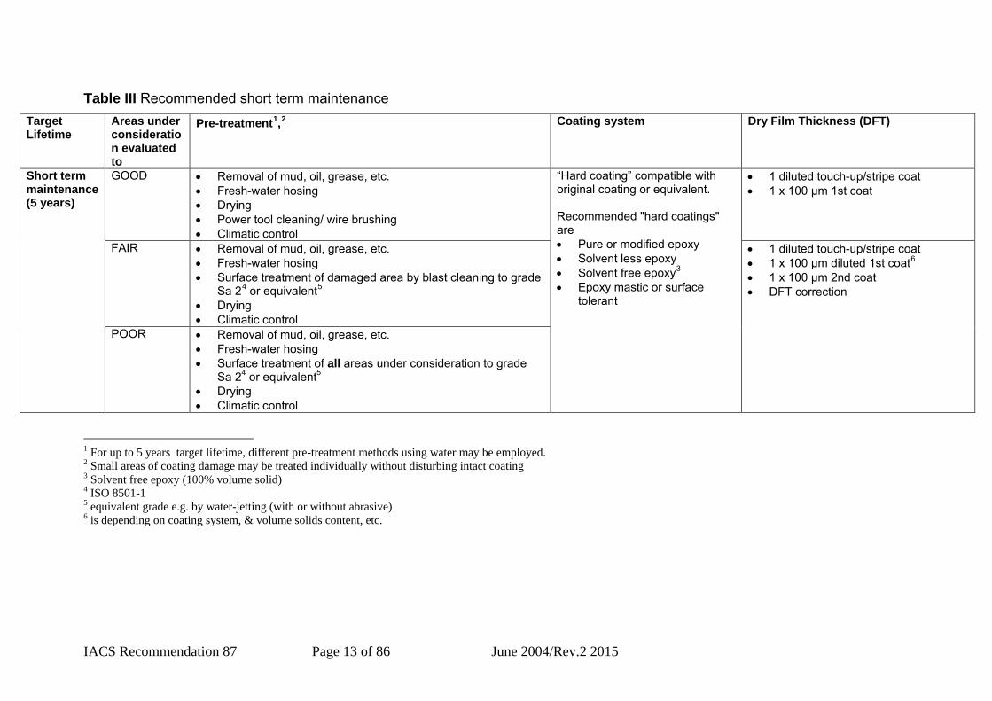
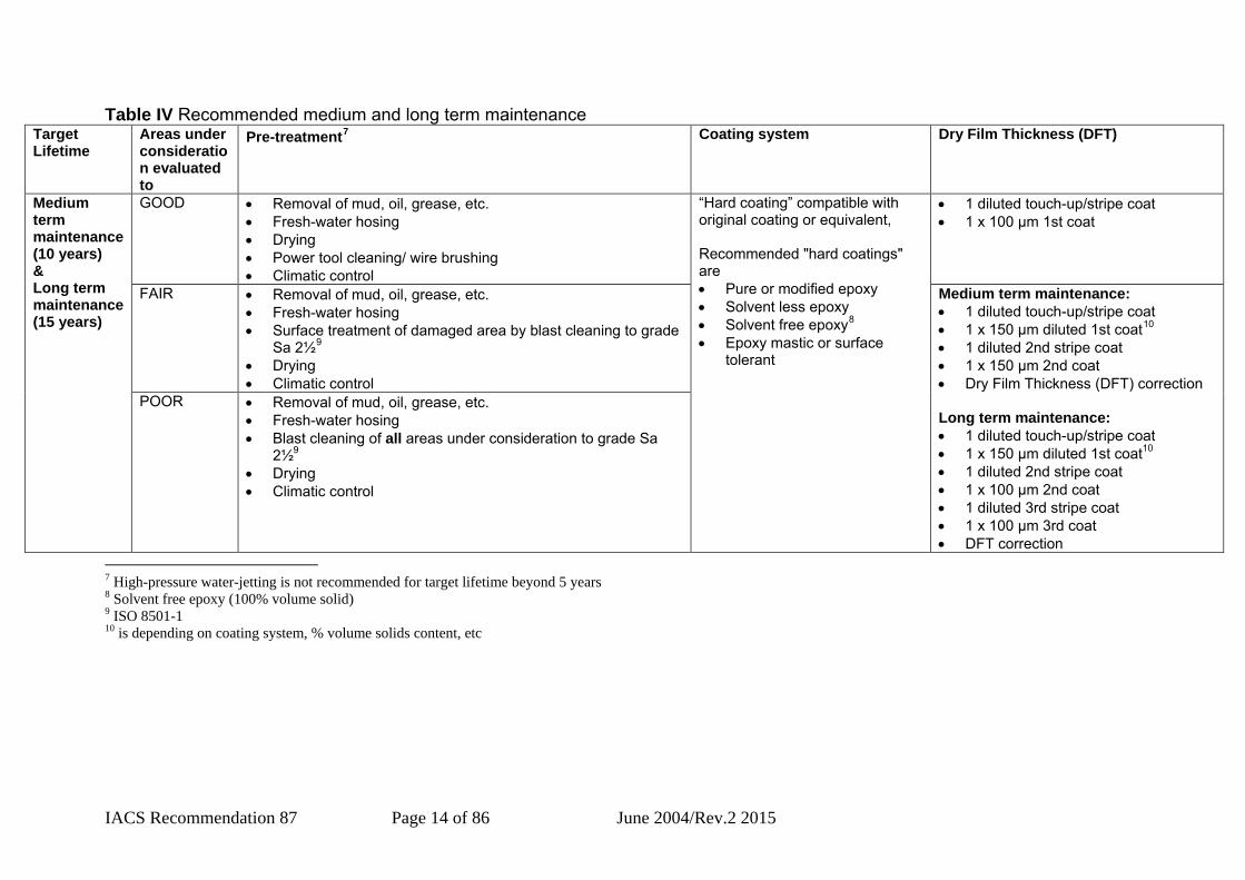
iv. Recommended maintenance The below Table III and Table IV describes the recommended short, medium and long term maintenance (e.g. 5, 10 and 15 years target lifetime respectively) to either maintain or to restore GOOD coating conditions.
IACS Recommendation 87 Page 13 of 86 June 2004/Rev.2 2015
Table III Recommended short term maintenance Target Lifetime
Areas under consideration evaluated to
Pre-treatment1,2 Coating system Dry Film Thickness (DFT)
Short term maintenance (5 years)
GOOD • Removal of mud, oil, grease, etc. • Fresh-water hosing • Drying • Power tool cleaning/ wire brushing • Climatic control
“Hard coating” compatible with original coating or equivalent. Recommended "hard coatings" are • Pure or modified epoxy • Solvent less epoxy • Solvent free epoxy3 • Epoxy mastic or surface
tolerant
• 1 diluted touch-up/stripe coat • 1 x 100 µm 1st coat
FAIR • Removal of mud, oil, grease, etc. • Fresh-water hosing • Surface treatment of damaged area by blast cleaning to grade
Sa 24 or equivalent5 • Drying • Climatic control
• 1 diluted touch-up/stripe coat • 1 x 100 µm diluted 1st coat6 • 1 x 100 µm 2nd coat • DFT correction
POOR • Removal of mud, oil, grease, etc. • Fresh-water hosing • Surface treatment of all areas under consideration to grade
Sa 24 or equivalent5 • Drying • Climatic control
1 For up to 5 years target lifetime, different pre-treatment methods using water may be employed. 2 Small areas of coating damage may be treated individually without disturbing intact coating 3 Solvent free epoxy (100% volume solid) 4 ISO 8501-1 5 equivalent grade e.g. by water-jetting (with or without abrasive) 6 is depending on coating system, & volume solids content, etc.
IACS Recommendation 87 Page 14 of 86 June 2004/Rev.2 2015
Table IV Recommended medium and long term maintenance Target Lifetime
Areas under consideration evaluated to
Pre-treatment7 Coating system Dry Film Thickness (DFT)
Medium term maintenance (10 years) & Long term maintenance (15 years)
GOOD • Removal of mud, oil, grease, etc. • Fresh-water hosing • Drying • Power tool cleaning/ wire brushing • Climatic control
“Hard coating” compatible with original coating or equivalent, Recommended "hard coatings" are • Pure or modified epoxy • Solvent less epoxy • Solvent free epoxy8 • Epoxy mastic or surface
tolerant
• 1 diluted touch-up/stripe coat • 1 x 100 µm 1st coat
FAIR • Removal of mud, oil, grease, etc. • Fresh-water hosing • Surface treatment of damaged area by blast cleaning to grade
Sa 2½9 • Drying • Climatic control
Medium term maintenance: • 1 diluted touch-up/stripe coat • 1 x 150 µm diluted 1st coat10 • 1 diluted 2nd stripe coat • 1 x 150 µm 2nd coat • Dry Film Thickness (DFT) correction Long term maintenance: • 1 diluted touch-up/stripe coat • 1 x 150 µm diluted 1st coat10 • 1 diluted 2nd stripe coat • 1 x 100 µm 2nd coat • 1 diluted 3rd stripe coat • 1 x 100 µm 3rd coat • DFT correction
POOR • Removal of mud, oil, grease, etc. • Fresh-water hosing • Blast cleaning of all areas under consideration to grade Sa
2½9 • Drying • Climatic control
7 High-pressure water-jetting is not recommended for target lifetime beyond 5 years 8 Solvent free epoxy (100% volume solid) 9 ISO 8501-1 10 is depending on coating system, % volume solids content, etc

IACS Recommendation 87 Page 15 of 86 June 2004/Rev.2 2015
References 1. Guidelines for ballast tanks coating systems and surface preparation,
TSCF, 2002 2. Condition evaluation and maintenance of tanker structures, TSCF, 1992 3. Guidance manual for tanker structures, TSCF, 1997 4. Guidelines for the Inspection and Maintenance of Double Hull Tanker
Structures, TSCF, 1995 5. IACS Unified Requirements Z10.1 (Rev.12), Z10.3 (Rev.7) and Z10.4
(Rev.2) 6. Guidelines for corrosion protection of sea water ballast tanks and hold
spaces, BV, 1995 7. Guidelines for Oil Tankers, BV, 2002 8. Guidelines for the selection, application and maintenance of corrosion
systems of ships ballast tanks, RINA Guidelines, 2000 9. Corrosion Protection of Tanks and Cargo Holds, DNV Technical Report
No. BGN-R3600197, 29th May 2000 10. Guidelines for the structural design of oil tankers, RINA, 2003

IACS Recommendation 87 Page 16 of 86 June 2004/Rev.2 2015
Appendix
A. Failures
i. Coating failures The coating failures considered in these Guidelines is the coating degradations within the intended coating service life. The main types are identified in the following items. Cracking This is a break-down in which the cracks penetrate at least one layer and which may be expected to result ultimately in complete failure. Such cracks may result from:
• over thicknesses of paint, • plastic structural deformations exceeding the elongation properties of the
paint film • localised fatigue stress, due to non appropriate design
Coating cracking
Flaking (loss of adhesion) It consists in the lifting of the paint from the underlying surface in the form of flakes or scales. The causes of a loss of adhesion may be the following ones:
• unsatisfactory surface preparation, • incompatibility with underlayer, • contamination between layers, • excessive curing time between layers
Coating flaking
Blistering It appears as a bubble formation scattered on the surface of a paint film, with a

IACS Recommendation 87 Page 17 of 86 June 2004/Rev.2 2015
diameter ranging from 3-4 mm to 20-30 mm. Blisters contain liquid, vapour or gas. Blistering is a localised loss of adhesion and lifting of the film, coming generally from osmosis due to one of the following causes:
• Solvent retention, • Improper coating application, • Soluble salt contamination under the paint film, due to an insufficient
cleaning of the surface. It is to be noted that in most cases there is no corrosion in an unbroken blister and many years of protection can be obtained if these blisters are left untouched.
Coating blistering
Blister around opening (8 years)
Due to a heavy overlap coating and poor workmanship, blisters have often been observed.
Blister on flat part (5 years)
Blisters have sometimes been observed on flat part and often been observed on areas which have difficulties to work on such as back of face plate of extrusions.
ii. Corrosion There are many forms of corrosion. The typical corrosion pattern which may be observed in a sea water ballast tank are described in the following items. General corrosion (uniform corrosion) General corrosion appears as non-protective, friable rust which can uniformly occur on tank internal surfaces that are uncoated. The rust scale continually breaks off, exposing fresh metal to corrosive attack. The anodic and cathodic areas on the

IACS Recommendation 87 Page 18 of 86 June 2004/Rev.2 2015
same piece of steel change with time, so those areas that were once anodes become cathodes and vice versa. This process allows the formation of a relatively uniform corrosion of steel.
General corrosion
Pitting corrosion (localised corrosion) Pitting corrosion is one of the most common forms that can be noted in ballast tanks. It is a localised corrosion that occurs on bottom plating, other horizontal surfaces and at structural details that trap water, particularly the aft bays of tank bottoms. For coated surfaces the attack produces deep and relatively small diameter pits that can lead to hull penetration. Pitting of uncoated tanks, as it progresses, forms shallow but very wide scabby patches (e.g. 300m mm diameter); the appearance resembles a condition of general corrosion. It is caused by the action of a localised corrosion cell on a steel surface due to the breaking of the coating (if present), to the presence of contaminants or impurities on the steel (e.g. mill scale) or to impurities present in the steel.
Pitting corrosion
Crevice corrosion Crevice corrosion is also localised corrosion that appears as pitting. The most common case occurs in cracks and generally on steel surfaces covered by scales and deposits. Typical examples are ship welding seams, pipe supports and bolts. The phenomenon is due to the fact that a small area of steel (i.e. the crevice, the crack or the area covered by debris) lacks oxygen and becomes the anode of a corrosion cell, while the remaining free surface, abundantly oxygenated, becomes the cathode. Since the anodic area is very small compared to the cathodic one, the corrosion process is extremely fast.

IACS Recommendation 87 Page 19 of 86 June 2004/Rev.2 2015
Erosion corrosion Corrosion due to erosion occurs when abrasives (i.e. sand or mud) held in the sea water impinges, with a certain velocity, an existing corrosion cell. The abrasives remove the accumulation of corrosion products keeping the metal clean and the corrosion active. Crude oil washing or hot and cold seawater washing can be considered as a particular erosion corrosion form. The greasy or waxy layer that, covers the steel surfaces, act as a corrosion inhibitor is removed, together with corrosion product, by the washing process keeping the steel clean and the corrosion active.
Bacterial corrosion Bacterial corrosion, called Microbiologically Influenced Corrosion (MIC) appears as scattered and/or localised pitting.
Steel surface affected by MIC
MIC is a form of corrosion originated by the presence of microscopic one-celled living organism including bacteria, fungi and algae. The corrosive bacteria live in water layer on the bottom of cargo oil tanks as well as in the sediment of water ballast tank bottom. Sulphate Reducing Bacteria (SRB) and Acid Producing Bacteria (APB) are the two most important and well known groups of micro-organisms, which cause corrosion. SRB and APB live together with other species of bacteria in colonies on the steel surfaces helping each other to grow. SRB’s are anaerobic in nature and obtain their needs of sulphur by a complex chemical reaction. During this reaction, the organism assimilates a small amount of sulphur, while the majority is released into the immediate environment as sulphide ions, which are hydrolysed as free H2S. In this way, SRB give rise to a corrosive process that supports the anodic dissolution of the steel. When bacteria have started to produce sulphide, the environmental condition becomes more favourable for growth, resulting in a population explosion. APB’s use the small quantity of oxygen of the water to metabolise hydrocarbons and produce organic acids such as propionic acid, acetic acid and other higher molecular acids. Since the APB’s “consume” the residual oxygen present in the sediment, they produce, under the colonies, a suitable and ideal environment for the SRB’s.

IACS Recommendation 87 Page 20 of 86 June 2004/Rev.2 2015
When active, the corrosion process originated by these bacteria can be extremely fast and can cause corrosion pits with a rate up to 1,5 – 3 mm per year, which is about five times higher than normally expected. Colonies of bacteria may appear like slimy black deposits on the steel surfaces. Stress corrosion Steel subject to stress or fatigue can be affected by fractures, even small. These areas act as a crevice and, due to low aeration, will corrode as already described. Furthermore, a fracture can also cause micro cracking on the protective coating, giving rise to a very active corrosion cell.
B. Corrosion prevention There are several methods to control the corrosion process. Each method has its advantages and limitations. In these Guidelines those concerning ballast tanks will be considered, specifying that although each method will be briefly described, the best solution in a total corrosion program is a suitable combination of all methods.
i. Protective coating (paints) Coatings can protect metals from corrosion by providing a barrier between the metal and the electrolyte, preventing or inhibiting the corrosion process or in some cases by a particular form of cathodic protection. The selection of the coating system, as well as the selection of its application procedure is extremely important since it affects the performance of the coating itself and consequently the life of the steel structure. The following photos show the ballast tanks of two ships with the same age of 13 years. During the construction, both ships were coated with an epoxy system, but the application procedure of the ship of the first photo was correctly done, while that one of the ship shown in the second photo was clearly poor. The photos are a clear example of the importance of the implementation of correct application procedure (surface preparation and paint system application) and coating selection.
Correct application, condition after 13 years
Poor application, condition after 13 years
If the protective coating is properly applied and a suitable maintenance program is performed, it can control the corrosion process of ballast tank surfaces for the

IACS Recommendation 87 Page 21 of 86 June 2004/Rev.2 2015
complete life of the ship (see the following photos).
Ballast tank after 16 years Ballast tank after 28 years
Paint systems A paint system is formed by one or more coats of paint, each of which is applied at a specified film thickness. This sequence of coats, called paint system, provides corrosion control by means of one or more of the following mechanisms:
• barrier protection (namely providing an insulating barrier between electrolyte and metal)
• chemical inhibition of corrosion reaction • cathodic protection when a coat of zinc rich primer, acting as sacrificial
anode, is applied Paint system is the logic and organic sequence of successive coats. It can be represented in a schematic generic form as: Primer - Undercoats – Finishing
• Primer is the first coat of the paint system. It has very important function such as, for example, to assure the adhesion of the whole system and to provide the required anticorrosive protection. It must be applied after a proper surface preparation, before which its quality could decay. Primer has to be overcoated according to the overcoating time and instructions recommended by the paint manufacturer.
• Undercoats are used to connect the primer with the finishing coat and to increase the total thickness of the system, as requested by the material to be protected and the location (e.g. bottom, topside etc.).
• Finishing provides specific characteristics to the area where it is applied: aesthetic appearance for topside and other exposed areas, anti-fouling protection for the underwater etc.
On ballast tanks in order to optimise corrosion prevention, the same paint is generally applied in more coats, providing more properties at the same time. It is useful, first of all, to clarify some terms of recent use:
• Hard coatings: Annex to IMO Resolution A.798(19) at item 2.6 defines Hard Coatings as "...a coating which chemically converts during its curing process, normally used for new constructions or non-convertible air drying coating which may be used for the maintenance purposes. Hard coating can be either inorganic or organic." All conventional paints are included in this definition, e.g. epoxy, polyurethane, zinc silicate, vinyl, etc.
• Semi-hard coatings: are coatings that, after drying, remain flexible and hard enough to be touched and walked upon without damaging them and that are not affected by water erosion during de-ballasting operations.

IACS Recommendation 87 Page 22 of 86 June 2004/Rev.2 2015
• Soft coatings: are coatings that do not dry, but remain permanently soft. Soft coatings are not recommended. Where Soft Coatings have been applied, safe access is to be provided for the surveyor to verify the effectiveness of the coating and to carry out an assessment of the conditions of internal structures which may include spot removal of the coating. When safe access cannot be provided, the soft coating is to be removed.
Paint systems for ballast tanks There are a lot of paint systems available for the protection of ballast tank surfaces. Each paint system proposed by the paint manufacturer has its number of coats and its specific film thickness. A schematic description of the various paint systems would be too vague and generic. For information only, the following table gives the basic characteristics of the paint systems until now more widely used for ballast tanks Table A Paint systems for ballast tanks
PAINT SYSTEM CHARACTERISTICS PURE or MODIFIED EPOXY Two-components
Light colour SOLVENT LESS EPOXY Two-components
Light colour SOLVENT FREE EPOXY (100% volume solids)
Two-components Light colour
EPOXY MASTIC and SURFACE TOLERANT
Two-components Light colour
Classification of hard coatings Hard coatings for ballast tanks may be classified according to a recognized standard such as for example, B1 as described in TSCF publication “Guidelines for ballast tanks coating systems and surface preparation”, 2002, Appendix (3)
ii. Cathodic protection Cathodic protection is a system of corrosion control by means of which a sufficient amount of direct current passing onto a metallic surface, converts the entire anodic surface to a cathodic area. Cathodic protection is effective only when the metallic surface is immersed. A cathodic protection system can be carried out by means of impressed current equipment or by sacrificial anodes. In ballast tanks the impressed current system is not permitted, due to the large amount of hydrogen gas produced by the process. Therefore only a system of sacrificial anodes (zinc or aluminium) is used. Anodes generate the necessary direct current so that they are corroded by their natural potential difference, protecting the surrounding steel. Pitguard anodes are suitable for arresting Sulphate Reducing Bacterial (SRB) attack.
iii. Design Corrosion prevention already starts during the design stage of the ship. A suitable structural design may control the corrosion by eliminating one or more components necessary for the corrosion reaction or by permitting an easier application of other methods of corrosion control and prevention. A good design must avoid:
• contact of dissimilar metals

IACS Recommendation 87 Page 23 of 86 June 2004/Rev.2 2015
• stagnation and water traps • crevices (e.g. skip/chain/intermittent welds or irregular welding seams), that
apart from the already described reasons, are difficult to protect with coating • irregular and sharp surfaces, because they are difficult to coat with the
correct film thickness • difficult-to-reach-areas, since they can prevent the correct application of the
coating In connection with repair, it is recommended to pay close attention to obtain a design favourable from a corrosion prevention point of view.
C. Surface preparation methods The main methods of surface preparation options are:
1. Hand chipping 2. Power tool cleaning; needle-gun, chipping-gun, rotary grinders, wire brushes,
etc. 3. Water-jetting 4. Ultra-high-pressure water-jetting 5. Slurry blasting 6. Water-jetting with grit injection 7. Ultra-high-pressure water-jetting with grit injection 8. Dry ice blasting 9. Sodium-bicarbonate (Baking Soda) blasting 10. Blast cleaning 11. Magnesium de-scaling 12. Sponge-jet blasting
1. Hand chipping is a fairly slow and labour intensive method that does not require much technical ability of the operator. It does not yield a clean substrate and coatings in seawater ballast spaces applied over hand chipped surfaces normally fail within 2 years. The so called "surface tolerant" primers will perform better, typically up to two years, whereas conventional primers will fail much earlier. 2. Power tool cleaning is a surface preparation method that can yield a very clean substrate. It is much more labour intensive than blast cleaning. Many tools such as rotary disc grinders and wire brushes, etc., will not clean inside crevices or shallow pits. Care is to be taken when using these tools e.g.:
- wire brushes which does not give a high surface profile - needle gun cleaning peens the surface and is not ideal.
The typical service period that a good coating will provide on power tool cleaned surfaces ranges from 2 to 5 years. The cleaner, and higher the surface profile (roughness) the greater the expected performance. As for the hand chipped surfaces a coating that is designed for a more compromised substrate will typically perform better than one that is less tolerant. Typically a well suited method for small spot repairs. 3. Water-jetting (WJ) is defined as having a water pressure in excess of 1000 bars (15,000 psi) is a relatively new process. The energy output and with it the cleaning ratio and success is highly dependent on the nozzle pressure, water volume and the design of nozzle. In general however, water-jetting will only remove loose rust, loose scale and loose paint at an acceptable production rate. It will not remove mill-scale or "black rust" (magnetite-scale). Painting over such scale will bring the performance expectation down to that of hand chipping. The process does not provide a surface profile to promote coating

IACS Recommendation 87 Page 24 of 86 June 2004/Rev.2 2015
adhesion and relies on the original abrasive blasted or corroded surface condition. Where there is no scale and a clean substrate is produced, although there will always be some re-rusting, the service life expectancy can be in excess of 5 years. Surface tolerant coatings are the best option for these surfaces. Warning is given here regarding so called "moisture tolerant" coatings. As the industry has not yet advanced to a point where it can accurately define or measure moisture content on a substrate, Owners could be subject to high risk if reliant on "moisture tolerant coatings". It is also to be noted that the use of water miscible components in the coating to assist with the dissolution (displacement) of the surface water is common in so called moisture tolerant coatings. Such species will however act as solutes in an osmotic couple with water and can be the direct cause of blisters. Moisture curing coating types e.g. polyurethanes etc., can use some or all of the surface water in its curing reaction. The same problem applies however since the amount of surface water cannot be measured and the stoichiometry of the reaction will not be ideal, any excess water may therefore cause exactly the same problems as for a non-moisture cured system. Water treatments below 68 bar (1000 psi) are not surface preparation methods but cleaning methods. NACE defined them as Low-pressure Washing, having water pressure below 68 bar while High-pressure Water Cleaning (HPWC) are termed the treatments having pressures from 68 to 680 bar (1000 to 10000 psi). 4. Ultra-high-pressure water-jetting (UHP-WJ) is defined by NACE as having a pressure in excess of 1500 bars (22,000 psi). Normally, such tools operate at 2000 bars (30,000 psi) or more. UHP-WJ produce better and faster cleaning than the water-jetting method does. The service life expectancy span for UHP-WJ can be 2 to 10 years depending on the cleanliness achieved, the amount of re-rusting and moisture control during painting. The same comments about coatings apply as for water-jetting. 5. Slurry blasting is using a modified dry grit blasting system with water as the propellant instead of air. There are no advantages (apart from a reduced dust and salt level) with this system compared to normal blast cleaning, but it has quite a few draw-backs, which is why it has not been used onboard ships to any significant degree. The service life expectancy will depend on the amount of re-rusting which is usually significant and varies from 3 to 5 years. This method does remove scale. The same comments about coatings apply as for water-jetting. 6. Water-jetting with grit injection has been used with success on some projects at sea. It produces a surface cleanliness about the same as slurry blasting but leaves much less wet grit to be removed. Re-rusting is a major problem and coating performance is dependent on how that matter is dealt with. Service life expectancy and coating comments will be the same as for the slurry blasting. 7. Ultra-high-pressure water-jetting with grit injection is interesting in that the production rate is reported to be very high, the grit consumption quite low and the re-rusting easily removed with water only using the same pump. It removes scale but is difficult to use in hard to reach areas. Properly operated this method could yield the same

IACS Recommendation 87 Page 25 of 86 June 2004/Rev.2 2015
performance expectation as grit blasting; e.g. in excess of 10 years. Coating comments, same as for water-jetting. 8. Dry-ice blasting is suggested from time to time. It clean at a similar rate as sodium bicarbonate blasting does. The equipment is expensive and produces cold surfaces that are subject to condensation onboard ships. Dry-ice blasting does not remove millscale or hard rust scale. This method has not been used to any significant degree onboard ships. If used, adequate ventilation must be arranged to offset any carbon dioxide build-up during melting of the dry ice. 9. Sodium-bicarbonate blasting ("baking-soda blasting") is another method that is proposed from time to time. It is interesting as the residue is water miscible and can be pumped out. The process must be followed by water rinsing as residual "baking-soda" will otherwise act as a solute to water in an osmotic couple that may cause blisters. Flash-back rusting will always be a problem and the service life expectancy is therefore in the water-jetting region. Sodium-bicarbonate blasting does not remove mill-scale or hard rust scale. 10. Blast cleaning - the work horse for corrosion prevention systems for a great many years is still the most cost effective method to yield a good substrate for the coating. The service life expectancy is in excess of 10 years. It is noted that there are several different types of grit, e.g. copper slag, garnet, sand, etc.: not all of them are suitable for use in all cases and care is therefore to be taken in selecting the most appropriate type for the case under consideration. When used as a repair process, great care is needed to minimise the amount of damage to the sound coating close to the areas being repaired. Invariably there will be some damage to the sound coatings, resulting in rust spots appearing. It is to be noted that there are a number of different grit blasting units i.e. open air, vacuum, etc. There is also a large selection of unit sizes available e.g. back-pack, minipot, 200 litre pot, "hopper" size, etc. The type used would depend on the project to be undertaken. 11. Magnesium de-scaling is sometimes used for ballast tank de-scaling and coating. Hydrogen gas formation is a major risk factor when using this method. It is also vital to wash the tank down immediately after the seawater used for the de-scaling has been pumped out or a detrimental white powder (calcium/magnesium carbonate) is formed on the surface of the steel. This method has had varying success and the service life expectancy will be regarded as in the water-jetting region of 2 to 5 years. 12. Sponge-jet blasting is a method that uses grit abrasives with a "sponged" surface. The method requires recycling which will involve an abrasive washing system. The interest is that adjacent areas may not be damaged by ricochets from blasting, hence it may be a useful means of preparing block joint surfaces within painted ballast spaces.
D. Pictorial ISO standards ISO 4628: Paint and varnishes - Evaluation of degradation of paint coatings -
Designation of intensity, quantity and size of common types of defect.

IACS Recommendation 87 Page 26 of 86 June 2004/Rev.2 2015
Part 1: General principles and rating schemes. Part 2: Designation of degree of blistering. Part 3: Designation of degree of rusting.
Part 4: Designation of degree of cracking Part 5: Designation of degree of flaking

IACS Recommendation 87 Page 27 of 86 June 2004/Rev.2 2015
ISO 4628/1: General principles and rating schemes. Table B Intensity of deterioration
Rating Intensity of change 0 1 2 3 4 5
unchanged, i.e. no perceptible change very slight, i.e. just perceptible change slight, i.e. clearly perceptible change moderate, i.e. very clearly perceptible change considerable, i.e. pronounced change sever, i.e. intense change
Table C Quantity of defects
Rating Quantity of defects (relative to a test area of 1 to 2 dm2)
0 1 2 3 4 5
none, i.e. no detectable defect very few, i.e. some just significant defects few, i.e. small but significant amounts of defects moderate, i.e. medium amount of defects considerable, i.e. serious amount of defects dense, i.e. dense pattern of defects
Table D Size of defects
Rating Size of defects 0 1 2 3 4 5
not visible under x 10 magnification only visible under magnification up to x 10 just visible with normal corrected vision clearly visible with normal corrected vision (up to 0,5 mm) range 0,5 to 5 mm larger than 5 mm

IACS Recommendation 87 Page 28 of 86 June 2004/Rev.2 2015
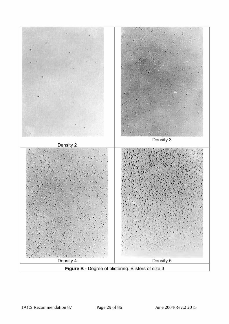
ISO 4628/2: Designation of degree of blistering.
Density 2
Density 3
Density 4
Density 5
Figure A - Degree of blistering. Blisters of size 2
IACS Recommendation 87 Page 29 of 86 June 2004/Rev.2 2015
Density 2
Density 3
Density 4
Density 5
Figure B - Degree of blistering. Blisters of size 3

IACS Recommendation 87 Page 30 of 86 June 2004/Rev.2 2015
Density 2
Density 3
Density 4
Density 5
Figure C - Degree of blistering. Blisters of size 4

IACS Recommendation 87 Page 31 of 86 June 2004/Rev.2 2015
Density 2
Density 3
Density 4
Density 5
Figure D - Degree of blistering. Blisters of size 5
IACS Recommendation 87 Page 32 of 86 June 2004/Rev.2 2015
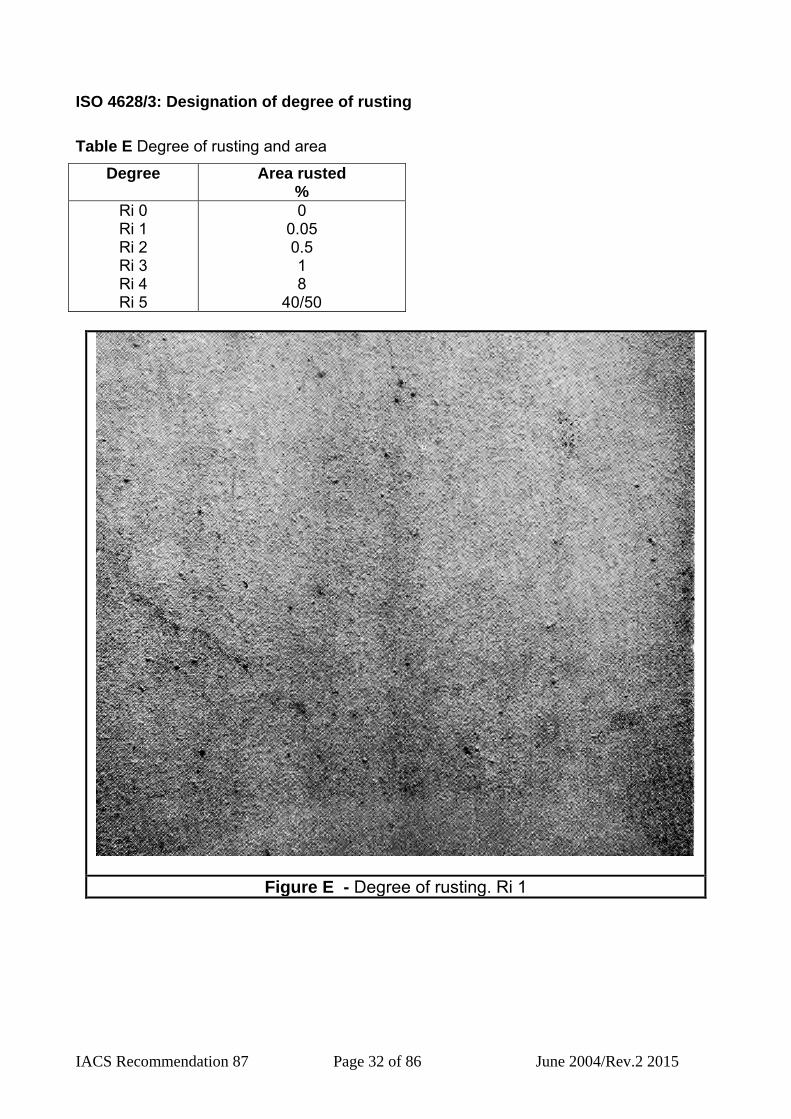
ISO 4628/3: Designation of degree of rusting Table E Degree of rusting and area
Degree Area rusted %
Ri 0 Ri 1 Ri 2 Ri 3 Ri 4 Ri 5
0 0.05 0.5 1 8
40/50
Figure E - Degree of rusting. Ri 1

IACS Recommendation 87 Page 33 of 86 June 2004/Rev.2 2015
Figure F - Degree of rusting. Ri 2
Figure G - Degree of rusting. Ri 3

IACS Recommendation 87 Page 34 of 86 June 2004/Rev.2 2015
Figure H- Degree of rusting. Ri 4
Figure I - Degree of rusting. Ri 5

IACS Recommendation 87 Page 35 of 86 June 2004/Rev.2 2015
ISO 4628/4: Designation of degree of cracking Table F Rating scheme for the designation of the size of cracks
Rating Size of cracks 0 1 2 3 4 5
not visible under x 10 magnification only visible under magnification up to x 10 just visible with normal corrected vision clearly visible with normal corrected vision large cracks generally up to 1 mm wide very large cracks generally more than 1 mm wide
Density 1
Density 2
Density 3
Density 4
Density 5
Figure J - Cracking without preferential direction

IACS Recommendation 87 Page 36 of 86 June 2004/Rev.2 2015
Density 1
Density 2
Density 3
Density 4
Density 5
Figure K - Cracking with one preferential direction (e.g. due to brush marks or wood grain)

IACS Recommendation 87 Page 37 of 86 June 2004/Rev.2 2015
ISO 4628/5: Designation of degree of flaking Table G Scale for the designation of the quantity of flaking
Class Flaked area %
0 1 2 3 4 5
0 0.1 0.3 1 3
15 Table H Scale for the designation of the approximate size of areas exposed by flaking
Rating Size of flaking (largest dimension)
0 1 2 3 4 5
not visible under x 10 magnification up to 1 mm up to 3 mm up to 10 mm up to 30 mm larger than 30 mm

IACS Recommendation 87 Page 38 of 86 June 2004/Rev.2 2015
Density 1
Density 2
Density 3
Density 4
Density 5
Figure L - Flaking without any preferential direction

IACS Recommendation 87 Page 39 of 86 June 2004/Rev.2 2015
Density 1
Density 2
Density 3
Density 4
Density 5
Figure M - Flaking with one preferential direction

IACS Recommendation 87 Page 40 of 86 June 2004/Rev.2 2015
E. Definitions and description of terms Abrasive: The agent used for abrasive blast cleaning; for example, garnet, grit, shot etc. Absorption: The process of soaking up, or assimilation of one substance by another. Adhesion: The bonding strength; the attraction of a coating to the substrate. Administration/Flag Administrations: Government of the state whose flag the ship is entitled to fly. Adsorption: The process of attraction to a surface; attachment; the retention of foreign molecules on the surface of a substance. Ageing: Progressive degradation of a coating in the long run. Air Entrapment: The inclusion of air bubbles in liquid paint or a paint film. Air Spraying: An application method by which paint is atomised by compressed air and transported to the surface. Airless Spraying: An application method by which the paint is forced to a great pressure (up to 350 kg/sq. cm.) and is atomised by forcing it through a tiny nozzle. Ambient temperature: The room temperature or temperature of surroundings. Amphoteric: Capable of reacting chemically either as/with an acid or as/with a base. and/or Suspect Areas. Anode: The corroding part of an electrochemical corrosion cell such as sacrificial anode or impressed current anode. The electrode at which corrosion occurs. Anticorrosive: Generic term defining paint used to protect metals from corrosion. Ballast Tank: A tank which is being used solely for water ballast or a tank which is used for both cargo and ballast will be treated as a Ballast Tank when substantial corrosion has been found in that tank. Batch: The amount of paint produced in a single production process and identified by a number assigned by manufacturer. Binder: The component of a coating that holds the paint together and fixed to the substrate. Common such binders are; epoxies, vinyl, urethane, etc. Blast cleaning: Cleaning with propelled abrasive. Bleeding: The appearance of a coloured substance on a newly painted surface from a previously painted substrate. The soluble substances causing this defect are for example: bituminous paint, specific organic pigments, etc.

IACS Recommendation 87 Page 41 of 86 June 2004/Rev.2 2015
Blistering: Bubbling in coating films normally caused by osmosis. Block Holding Primer (BHP): Primer applied at block stage to reduce the amount of in-situ secondary surface preparation. Not a pre-construction primer. Blushing: Development of a milky appearance on a coating surface during drying process caused by humidity and/or from the precipitation of one or more solid components of the paint. Body: Improper term to indicate the high percentage of volume solid of a paint. Breakdown of coating: Defects in the coatings like rust penetration, blistering, flaking and cracking. Brittle failure: Cracking and/or other failure normally encountered with hard, low ductility glassy objects and films. Brittleness: Degree of resistance to cracking or breaking by bending. Lack of resistance to cracking or breaking when bent. Bubbling: Coating defect, temporary or permanent, in which small bubbles of air or solvent or both are present in the applied film. Cargo Area: That part of the ship that contains cargo tanks, slop tanks and cargo/ballast pump rooms, cofferdams, ballast tanks and void spaces adjacent to cargo tanks and also deck areas throughout the entire length and breadth of the part of the ship over the above mentioned spaces. Cathode: The electrode at which corrosion does not usually occur. Cathodic Protection: Corrosion prevention by sacrificial anodes or impressed current. Chalking: Formation of powder on a coated surface as a result of weathering. Checking Chipping: Cleanliness method of steel by removing paint, rust and mill scale, or other material by mechanical tools. Clean surface: One free of contamination (including non-visible contamination such as soluble salts). Close-up Inspection: An inspection where details of structural components are within the close visual inspection range of the surveyors, i.e. normally within reach of hand. Close-up Survey: A survey where the details of structural components are within the close visual inspection range of the surveyor, i.e. normally within reach of hand. Clotted: Irreversible gelatinisation of a paint that becomes unusable. Coat of paint: One layer of dry paint, resulting from a single wet application.

IACS Recommendation 87 Page 42 of 86 June 2004/Rev.2 2015
Coating Material: Compound generally liquid, mastic or powder, forming a solid, filling protective and/or decorative coating. Coating system: A number of coats separately applied, in a predetermined order, at suitable intervals to allow for drying and curing, resulting in a completed job. Coating, Lining: Term used to define various products that are applied on steel to protect it from corrosion and/or to decorate it. Coatings: Surface coverings; paints; barriers. Cohesion: Property of holding together of a single material. Compatibility: Attitude of a paint to be applied on another already dry coating. Conductivity: The inverse of the resistance (Ohm cm). In these guidelines: conductivity, i.e. specific electrical conductance, of an electrolyte, as salt and water mixtures (seawater). Corrosion prevention/protection system: A system designed for protecting the metal substrate from corrosion. For the purpose of these Guidelines, a corrosion prevention/protection system is 1) a hard coating, or 2) a hard coating supplemented by anodes Corrosion rate: The rate usually in mm/year, at which the corrosion process proceeds. The corrosion rate is always to be calculated from metal loss on the surface, even when occurring on both sides of a steel plate. Corrosion rate shall not be confused with "steel thickness reduction rate". Corrosion: Decay; oxidation; deterioration due to interaction with environment. Cracking Cracking of coating: Defect with fracture in the coating in at least one coat, often down to the substrate. Related expression is checking, which is surface cracking and crocodilling. Critical Structural Areas: Are locations which have been identified from calculations to require monitoring or from the service history of the subject ship or from similar or sister ships (if available) to be sensitive to cracking, buckling or corrosion which would impair the structural integrity of the ship. Cross Application: System of application by airless spraying and by brush consisting of crossing the various coats at right angles. Cross Hatch Test: A method for testing adhesion of a coating, performed by a parallel series of crosshatch cuts near each other. Cross-spray: Spraying first in one direction and second at right angles.

IACS Recommendation 87 Page 43 of 86 June 2004/Rev.2 2015
Curing agent: Hardener; promoter. Curing Time: Time required by a coating to reach its complete properties and mechanical characteristic. Curing: Setting up; hardening. Curtaining: Special form of sagging by which the film appears locally with high thickness and with flakes similar to drape curtains. Dew point: Temperature at which moisture condenses. DFT: Dry film thickness. Diluent: A liquid which lowers viscosity and increases the bulk but is not necessarily a solvent for the solid ingredients; a thinner. Discing: Surface preparation method carried out with an abrasive disc assembled on a pneumatic or electric tool. Discoloration: Colour change of a coating after application, normally caused by exposure to sunlight or chemical atmospheres. Double Hull Oil Tanker: For the purpose of these Guidelines a Double Hull Oil Tanker is a ship which is constructed primarily for the carriage of oil in bulk, which has the cargo tanks protected by a double hull which extends for the entire length of the cargo area, consisting of double sides and double bottom spaces for the carriage of water ballast or void spaces. For other classification purposes, the definition provided in IACS URs and/or in Classification Societies Rules is to be used. Dry Film Thickness (DFT): The thickness of the paint film, after drying and curing. Dry spray: Over spray or bounce back; sand finish due to spray particles being partially dried before reaching the surface. Dry to handle: Time interval between application and ability to pick up without damage. Dry to recoat: Time interval between application and ability to receive next coat satisfactorily. Dry to touch: Time interval between application and tack-free time. Dryers: Substances that incorporated in relatively small percentages in the paint accelerate the drying process. Drying time: Time interval between application and final cure. Drying: Process by which coatings change from a liquid to solid state due to evaporation of the solvent, physical/chemical reactions of the binder or a combination of these factors. Dulling or Tarnishing: Loss of gloss of a coating.

IACS Recommendation 87 Page 44 of 86 June 2004/Rev.2 2015
Edging: Striping. Elasticity: Term improperly used to indicate the flexibility of the coating, corresponding to a permanent plastic deformation. Electrochemical cell: See electrolytic corrosion. Electrolytic corrosion: Corrosion occurring in an electrolyte, i.e. an electrically conductive liquid such as salt water. Anodes and cathodes formed on the steel surface, together with an electrolyte and the metallic pathway through the metal, constitute electrochemical cells. Enamel: A finish coat of paint that shows a smooth, gloss surface after drying. Epoxy amine: Amine cured epoxy resin. Epoxy resins: Film formers (binders) usually made from bisphenol-A and epichlorohydrin, resins containing the oxyrane ring. Erosion: Gradual and irregular destruction of coating surface caused by a mechanical or also by a chemical-physical action. Explosion limits: A range of the ratio of solvent vapour to air in which the mixture will explode if ignited. Below the lower explosion limit (LEL) or above the higher explosion limit (HEL) the mixture is too lean or too rich to explode. The critical ratio runs from about one to 7 percent of solvent vapour by volume at atmospheric pressure. Extender: Inert substance, for certain characteristics similar to pigments, but without or of low hiding power, used as a paint component for technical needs or for economic reasons (filling) (see “Pigments”). Feather edge: Tapered edge. Ferrous: Iron containing. Film integrity: Degree of continuity of film. Film thickness: The thickness of a coating layer or a multilayer coating system. Minimum and maximum values are the only relevant numbers when dealing with corrosion protection. Film: A layer of coating material applied on a surface. The film just applied, before evaporation of the solvents is called “wet film”; the dry paint film, after solvent evaporation, “dry film”. Fingers (airless): Broken spray pattern, finger like. Finish: Term used to define indifferently the final coat in a paint system or the general aspect of a painted surface after drying.

IACS Recommendation 87 Page 45 of 86 June 2004/Rev.2 2015
Flaking: Detachment of a coating from the surface, in the form of flakes. Flash off: Starting stage of drying process, during which most of the solvents evaporate from the coating. Flash Point: The lowest temperature at which a liquid gives off sufficient vapour to form an ignitable mixture with the air near the surface of the liquid. Flexibility: The degree at which a coating is able to conform to movement or deformation of it's supporting surface without cracking or flaking. Flooding-Floating: Differentiated separation of pigments on a coating surface Flow: Degree to which a wet paint film can level out after application so as to eliminate brush marks and produce a smooth uniform finish. Forced drying: Acceleration of drying by increasing the temperature above ambient temperature accommodated by forced air circulation. Galvanic corrosion: Corrosion of dissimilar metals in electrical contact. Galvanising: Anticorrosive system which consists in dipping a steel structure, into melted zinc at a temperature of approximately 450°C. Galvanized steel: Zinc plated steel applied in a molten bath of zinc. Gelling: Partial or complete transformation of a paint into a mass similar to a gelatine. General corrosion: Evenly distributed corrosion attack on steel surface. Generic: Belonging to a particular family. Glazing: Coat intentionally applied with a small thickness. Gloss: Aptitude of a surface to reflect the light in certain conditions. Grit: An abrasive obtained from slag and various other materials. Guide: Guides are publications which give information and advice on technical and formal matters related to the design, building, operation, maintenance and repair of ships (and other objects) to yield a specific goal. Guidelines: See Guide. Hard coating: A coating which chemically converts during its curing process, normally used for new constructions or non-convertible air drying coating which may be used for the maintenance purposes. Hard coating can be either inorganic or organic. All conventional paints are included in this definition, e.g. epoxy, polyurethane, zinc silicate, vinyl, etc. Hard rust scale: Sever general corrosion accumulated in layers adhering tightly to the steel surface.

IACS Recommendation 87 Page 46 of 86 June 2004/Rev.2 2015
Hardener, Curing agent, Catalyst: Component of a two-pack paint that mixed with a binder creates a chemical reaction forming a harder and resistant film. Hardness: Resistance of a dry coating to scratching or to superficial deformation due to pressure. Hiding Power: The ability of a coating material to hide, after drying, the colour of surface underneath. Hold point: A stage in the production process where the work is stopped for an inspection to take place. Holiday: Pinhole; skip; discontinuity; voids. Hot Spraying: Spray application of a coating that has been heated to reduce its viscosity in special equipment. Humidity: Measure of moisture content; relative humidity is the ratio of the quantity of water vapour in the air to the greatest amount possible at the given temperature. Saturated air is said to have a humidity of 100%. Hydroxyl: Chemical radical; OH; basic nature. Hygroscopic: Having a tendency to absorb water. Immersion: Referring to an environment which is continually submerged in a liquid, often water. Impressed current: Cathodic protection system in which the current is supplied at the anode from an external source. Induction time: The period of time between mixing of two component products and the moment they can be used . Inert: Not reactive. Inhibitive pigment: One which retards a corrosion process. Inhibitor: An agent added to retard corrosion. Inorganic coating: Those employing inorganic binders or vehicles. Inorganic: Material containing primarily ionic bonds and elements other than C and H. In-situ: In these guidelines meaning work at the final hull stage; Plate stage - to - Panel stage - to - Block stage - to - Super-block stage - to -In-situ stage. Inspection Hold point: Point in the production process where work will stop to enable inspection to take place.

IACS Recommendation 87 Page 47 of 86 June 2004/Rev.2 2015
Inter-coat contamination: Presence of foreign matter between successive coats. Job-specification: Detailed working procedure outlining each step in the surface preparation and coating processes; including inspection hold points, thickness ranges, etc. Lead free: Contains by weight less than 0.5% lead for industrial products and less than 0.06% lead in consumer products. Light colour: Light colour in these guidelines means a colour that reflects light to an extent that a simple flash light (hand torch) will make inspection easy and fast. Normally light grey, buff, off-white, swimming pool blue/green, etc. easily distinguishable from rust. Linings: Internal barriers; linings may be coated or sheet type. Local breakdown of coating: Various kinds of more or less concentrated or spot-wise defects in the coatings like rust penetration, blistering, flaking and cracking. Maintenance painting: (1) repair painting; any painting after the initial paint job; in a broader sense it includes painting of items installed on maintenance; (2) all painting except that done solely for aesthetics. Masking: Covering areas not painted. Mastic: A heavy bodied coating of high build.: Material Safety Data Sheet: Document published by paint manufacturer in which components of the paints and all the safety requirements are given. Mechanical cleaning: Power tool cleaning, by means of grinding disc, wire brush or similar. Mill scale: Oxide layer formed on steel by hot rolling. Miscible: Capable of mixing or blending uniformly. Mist coat: Thin tack coat; thin adhesive coat. Common practice to wet an inorganic zinc layer, and permit air escape, before full build when top coating. Moisture vapour transmission (MVT): Moisture vapour transmission rate through a membrane. MSDS: Material Safety Data Sheet Non-ferrous: A term used to designate metals or alloys that do not contain iron; example; brass, aluminium, magnesium, copper, etc. NSF: National Sanitation Foundation; Organization in US certificating coatings for potable water tanks. Oil Tanker: for the purpose of these Guidelines an Oil Tanker is a ship which is constructed primarily to carry oil in bulk and includes ship types such as combination

IACS Recommendation 87 Page 48 of 86 June 2004/Rev.2 2015
carriers (Ore/Oil ships etc.). For other classification purposes, the definition provided in IACS URs and/or in Classification Societies Rules is to be used. Orange peel: Appearance similar to orange peel, that can be seen on a film applied by airless spraying due to incomplete levelling. Organic: Containing carbon. Osmosis: Transfer of liquid through a paint film or other membrane as the result of a solute/solvent couple. Osmotic blistering: Formation of blisters containing liquid through osmosis. Overall Inspection: An inspection intended to report on the overall condition of the hull structure and determine the extent of additional close-up inspections. Overall Survey: A survey intended to report on the overall condition of the hull structure and determine the extent of additional Close-up Surveys. Owner: Owner or Owners representative. Paint system: The complete number and type of coats comprising a paint job. In a broader sense, surface preparation, pre-treatments, dry film thickness, and manner of application are included in the definition of a paint system. Peeling: Disbonding of particles of a coating from substrate in the form of strips, due to loss of adhesion. Peen: To draw, bend or flatten by or as if by hammering with a peen (wedge-shaped end of the head of a hammer). Peened: As if hammered by a rounded tool or shot. Permeability: Quality or state of being permeable. pH value: Measure of acidity or alkalinity; pH 7 is neutral; the pH value of acids ranges from 1 to 7, and of alkalis (bases) from 7 to 14 in water solution. Pigments: Insoluble coloured particles dispersed in a coating material in order to define appearance, structure and functionality of the final film. Pinholes: Presence of small holes in a coating that are formed during application or drying. Pitting: Cavity in a metallic surface, due to localised corrosion. Plasticizer: A paint ingredient which imparts flexibility. Polymerization: Formation of large molecules from small ones. Pot-life: Time interval after mixing during which liquid material is usable with no difficulty.
IACS Recommendation 87 Page 49 of 86 June 2004/Rev.2 2015
Power Tool Preparation: Surface preparation method carried out by mechanical tools, pneumatic or electric such as abrasive discs, wire brush, sandpaper etc. Preventive maintenance painting: Spot repair painting; touch-up or full coats of paint before rusting starts. Prime coat: First coat. Primer: General term used to define the first coat of a paint system applied to provide adhesion and/or corrosion protection. Product Data Sheet: Document published by paint manufacturer in which the characteristic of the product, the method to use, the instructions for application and storage are indicated. Profile depth: Average distance between tops of peaks and bottom of valleys on the surface. Profile-surface: Surface contour as viewed from edge. Prompt and Thorough Repair: A permanent repair completed at the time of survey to the satisfaction of the Surveyor, therein removing the need for the imposition of any associated condition of classification. Protective Coating: Usually epoxy coating or equivalent. Other coating systems may be considered acceptable as alternatives provided that they are applied and maintained in compliance with the manufacturer’s specification. Protective life: (also called Useful life) Interval of time during which a paint system protects substrate from deterioration. Recoat time: Time interval required between application of successive coats. Repainting: Repetition of a complete painting operation including surface preparation. Representative Tanks: Those tanks which are expected to reflect the condition of other tanks of similar type and service and with similar corrosion protection systems. When selecting Representative Tanks account is to be taken of the service and repair history onboard and identifiable Critical Areas Resin: The film former; binder. Roller Application: Hand application of a coat of paint using an absorbing roller on a surface. Rugotest: Profile comparator from RUPERT & CO. LTD, UK; by BS2634 and ISO2632. Sacrificial anode: Anode made from less noble metal than steel in the galvanic series, (usually zinc or aluminium). When immersed, the anode protects the steel by coming into solution.

IACS Recommendation 87 Page 50 of 86 June 2004/Rev.2 2015
Sags: Runs Salt fog test: A cabinet designed to accelerate the corrosion process in evaluating coatings; combines 100% humidity with a 5% salt concentration at 100°F in an enclosed cabinet, as in ASTM - B 117. Sandblast: Blast cleaning using sand as an abrasive. Sandpapering: Generic term identifying various methods used to smooth or in some cases to roughen a coating surface. In particular, sandpapering is a smoothing carried out with abrasive paper. Saponification: The alkaline hydrolysis of fats/oils whereby a soap is formed; typical reaction between alkyds and galvanized metals resulting in peeling or from cathodic protection. Scattered breakdown of coating: Various kinds of evenly distributed defects in the coatings like rust penetration, blistering, flaking and cracking. Semi-hard coating: Coating that, after drying, remain flexible and hard enough to be touched and walked upon without damaging them and that are not affected by water erosion during de-ballasting operations. Service life: See Protective life. Settling: Accumulation of pigments and fillers in the bottom of a paint container. Shop primer: An inexpensive, rust inhibiting primer designed to protect steel from general weathering immediately after plate fabrication and before final coating processes. Shot blasting: Blast cleaning using steel shot as the abrasive. Shrinkage: Decrease in volume on drying. Skinning: Solidification process of the superficial part of paint in the can due to oxidation, evaporation, coagulation etc. Soft coating: Defined as coatings that does not dry, but remain permanently soft. Solid Content: Non-volatile part of a paint, see also solids by volume. Solids volume: Formulated percent of total paint volume occupied by non-volatile parts of the coating. Solubility: Degree to which a substance may be dissolved. Solution: A liquid in which a substance is dissolved. Solvent entrapment: The encapsulation of solvent within a cured paint film.
IACS Recommendation 87 Page 51 of 86 June 2004/Rev.2 2015
Solvent: A liquid in which another substance may be dissolved. Solvent-Free: Paint without volatile binder (also called 100% volume solid). Solvent-Less: Paint containing a small percentage (generally 10/15%) of volatile binder. Spaces: Separate compartments including holds and tanks. Specification: A set of instructions detailing the plan for coating of a project; a list of criteria for a coating. Spontaneous degradation: Coating degradation that is controlled and directed internally: self-acting: developing without apparent external influence, force, cause, or treatment. Spot repair: Preventative maintenance; repainting of small areas. Spot rusting: Rusting in spot without visible failure of coating. Spreading Rate: Surface in square metres covered by one litre of paint at a specified thickness. Stripe Coating: Painting method used before a general coat on positions (weld, back, edge, corner etc.) where it is not easy to achieve the final thickness with the simple airless spray application. Striping: Edge, weld, scallop painting prior to priming. Substantial Corrosion: An extent of corrosion such that assessment of corrosion pattern indicates wastage in excess of 75% of allowable margins, but within acceptable limits. Substrate: Surface to be painted; in this context carbon steel, stainless steel, galvanized steel and all surfaces that can affect the corrosion rate or can corrode. Surface tension: Cohesive force on liquid surface. Suspect Areas: Locations showing Substantial Corrosion and/or are considered by the Surveyor to be prone to rapid wastage. Sweat-in time: Time for a two component material to start the reaction that allows the two components to become soluble in each other; Induction time. Sweating: Condensing moisture on a substrate. Swelling: Increasing in volume. Tg: Glass transition temperature - the temperature at which a coating is transformed from the rubbery to the glassy state.; e.g. becomes a brittle hard film. Or, the temperature under which the coating becomes rubbery and able to deform. Thermo-Hygrometric Condition: The environmental conditions that are present during surface preparation and paint application.

IACS Recommendation 87 Page 52 of 86 June 2004/Rev.2 2015
Thermosetting: Becomes rigid under heat due to chemical cross linking and cannot be remelted. Thinners: Volatile organic liquids for reducing viscosity; diluents. Thinning Ratio: Percentage of solvents to add to a paint, to make it suitable for a defined application system. Thixotropic: False-bodied; a gel which liquefies with agitation but gels again on standing. Thixotropy: Characteristic of a coating material to reach a viscosity reduction when shaken, stirred or other mechanical operations and that readily recovers its original viscosity when allowed to stand. Touch drying: Drying is the stage of film formation in which, when exercising a light pressure with the finger, no sign remains and it is not sticky. Touch-up painting: Spot repair painting usually conducted a few months after initial painting. Also, manual painting to correct thickness deficiencies. Touch-up: Operation of repair of spot damage coated surface. Transverse Section: Includes all longitudinal members such as plating, longitudinals and girders at the deck, side, bottom, inner bottom and longitudinal bulkheads. TSCF: Tanker Structure Co-operative Forum Turn: To oxidize. Two-Pack Paints: Paints stored in two separate containers and that have to be mixed in the correct proportion before application. Useful life: See Protective life. Varnish, Lacquer: Non-pigmented coating material. Vehicle: The liquid portion of paint in which the pigment is dispersed. It is made up of resin and solvent. Viscosity: A measure of fluidity of a liquid. Volume Solids: Non-volatile part of a coating compound, which after drying forms the coating. Walk-on-time: Time at which a coating is dried/cured enough so that it can be walked upon without being damaged. Weld joints: Beads of weld joining two members. Weld slag: Amorphous deposit formed during welding.

IACS Recommendation 87 Page 53 of 86 June 2004/Rev.2 2015
Weld spatter: Beads of metal left adjoining a weld. Weld splatter: See weld spatter. Wet Film Thickness: The thickness of paint film just applied and before evaporation of the volatile part. Wet-on-Wet: Paint technique consisting of the application of a coat on a previous one not yet dry. The result is of one film that dries as a whole. The process requires specific paints. Wetting strength: The maximum distance or penetration the vehicle is capable of delivering the paint or coating assembly in a vertical or horizontal direction on a specific substrate. Wetting time: The time required for a vehicle to reach the end point of a distance and penetration on a metal. Wrinkling: Coating defect due to a non-homogeneous solidification of the paint film with wrinkling of the surface coat. Zinc rich coating: Products containing > 86% (by weight) metallic zinc in the dry film. Zinc silicate: Inorganic zinc coating.

IACS Recommendation 87 Page 54 of 86 June 2004/Rev.2 2015
Typical nomenclature for single hull: Typical transverse section of single hull tanker

IACS Recommendation 87 Page 55 of 86 June 2004/Rev.2 2015
Typical nomenclature for double hull: Typical transverse section of double hull tanker
IACS Recommendation 87 Page 56 of 86 June 2004/Rev.2 2015
F. Pertinent Standard STANDARD SUBJECT STANDARD SUBJECT
ASTM 56 flash-point ASTM 711 drying times of
coatings ASTM 1005 thickness
measurements ASTM 1259 binder/pigment/
volatile/solids content
ASTM 1310 flash-point ASTM 1640 drying times of
coatings ASTM 1953 drying times of
coatings ASTM 2240 hardness ASTM 262 binder/pigment/
volatile/solids content
ASTM 2832 binder/pigment/ volatile/solids content
ASTM 3278 fiash-point ASTM D93 fiash-point ASTM D522 elongation, bending
over mandrel ASTM D610 degree rusting ASTM D658 abrasion resistance ASTM D659 degree chalking ASTM D660 degree checking ASTM D661 degree cracking ASTM D662 degree erosion ASTM D714 degree blistering ASTM D772 degree flaking ASTM D821 abrasion resistance ASTM D968 abrasion resistance ASTM D1141 synthetic seawater ASTM D1186 dry thickness,
ferrous ASTM D1200 viscosity ASTM D1212 wet thickness
reading ASTM D1397 abrasion resistance ASTM D1400 dry thickness, non-
ferrous ASTM D1653 water vapor
transmission ASTM D1737 elongation, bending
over mandrel
ASTM D2134 hardness ASTM D2197 adhesion, scrape
test ASTM D2370 tensile elongation,
free film ASTM D2485 heat resistance
testing ASTM D2485 resistance to high
temperature ASTM D2697 binder/pigment/
volatile/solids content
ASTM D2794 impact resistance ASTM D3732 drying times of
coatings ASTM G8 cathodic
disbondment ASTM G14 impact resistance ASTM G53 cyclic test ASTM MD570 water absorption of
plastics and free coating films
ASTM MD3258 porosity of films ASTM MD3276 guidance for
inspectors ASTM MD3359 adhesion by tape
test ASTM MD3363 hardness by pencil
test ASTM ME376 eddy current gauge BS 2634 surface roughness
comparator BS 2691 thickness
measurements BS 3900 part C5 thickness
measurements BS 3900 part C5 wet film thickness BS 3900 Part E4 elongation, cupping
of coated plates (Erichsen test)
BS 3900 Part E1 elongation, bending over mandrel
BS 3900 Part E3 impact resistance BS 3900 Part E7 impact resistance BS 3900 PART G7 heat resistance
testing BS 4164 hardness

IACS Recommendation 87 Page 57 of 86 June 2004/Rev.2 2015
BS 4164 heat resistance testing
BS 4232 degrees of surface preparation
BS 4692 heat resistance testing
BS 5493 wet film thickness BS 6374 holiday / pinhole
detection DIN 1342 viscosity DIN 2691 thickness
measurements DIN 51550 viscosity DIN 51755 flash-point DIN 51758 flash-point DIN 53156 elongation, cupping
of coated plates (Erichsen test)
DIN 53177 viscosity DIN 53213 flash-point DIN 55928 degrees of surface
preparation ISO 1517 drying times of
coatings ISO 2808 thickness
measurements ISO 2812-2 immersion/freeze/
dry test ISO 3233 binder/pigment/
volatile/solids content
ISO 4828-4 paint and varnishes- evaluation of degradation of paint coatings
ISO 6270 condense chamber test
ISO 7253 salt spray testing ISO 8501-1 surface preparation ISO 8501-3 steel surface
imperfections ISO 8502-1 soluble iron ISO 8501-3 steel preparation ISO 8502-2 labtest- chlorides ISO 8502-3 dust assessment ISO 8502-4 condensation
probability ISO 8502-6 field extraction –
chlorides
ISO 8502-9 field conductimetric determination of water soluble salts
ISO 8503-1 surface roughness spec.
ISO 8503-2 surface roughness comparator
ISO 8503-3 surface roughness microsc.
ISO 8503-4 surface profile, Stylus instrument
ISO 8504-1 surface preparation methods
ISO 8504-2 abrasive blast cleaning
ISO 8504-3 power & hand tool cleaning
ISO 8502-10 titrimetric determination of water soluble salts
ISO 8503-1 roughness definition ISO 8503-2 roughness
comparator ISO 8503-3 roughness, Fucus
microscope ISO 8503-4 roughness, Stylus
instrument NACE No.7 water jetting/blasting
standards NACE TM 170-70 degrees of surface
preparation NACE RP0178 weld and steel
standards NACE RP0274 holiday/pinhole
detection SIS 055900 degrees of surface
preparation SIS 162201 hardness SIS 184153 drying times of
coatings SIS 184160 thickness
measurements SSPC PA2 thickness gauge
calibration SSPC SP 1 substrate
degreasing SSPC VIS 1 degrees of surface
preparation, blasted steel
IACS Recommendation 87 Page 58 of 86 June 2004/Rev.2 2015
SSPC VIS 3 degrees of surface preparation, power tooled steel
SSPC-VIS4(1) water jetting/blasting standards

IACS Recommendation 87 Page 59 of 86 June 2004/Rev.2 2015
G. Tables comparing commonly used standards Table I Comparison of blasting standards
Standard Highest degree = White metal
Good degree = near white
ISO 8501-1 Sa 3 Sa2 ½ SIS 055900 Sa 3 Sa2 ½ DIN 55928 SA 3 Sa2 ½ BS 4232 First Quality Second Quality NACE TM170-70 No.1 No.2 SSPC SP 5 SP 10 Table J Comparison of power tool standards
Standard Highest degree High degree Lower degree ISO 8501-1 NA St 3 St 2 ½ SIS 055900 NA St 3 St 2 1/2 DIN 55928 NA St 3 Sa 2 1/2 SSPC SP 11 SP 3 SP 2 Table K Correlation between ISO and ASTM rating systems for blisters
Denisity Size ASTM ISO ASTM ISO
None (less than few) Few Medium Medium – Dense Dense
0 1 2 3 4 5
(smaller than 8)
8 6 4 2
1 2 3 4 5
Table L Correlation between ISO and European rust scales
ISO rust scale European rust scale Ri 0 Ri 1 Ri 2 Ri 3 Ri 4 Ri 5
Re 0 Re 1 Re 2 Re 3 Re 5 Re 7
Table M Approximate correlation between ISO and ASTM rust scales
ISO rust scale ASTM D 610 Ri 0 Ri 1 Ri 2 Ri 3 Ri 4 Ri 5
10 9 7 6 4
1 to 2

IACS Recommendation 87 Page 60 of 86 June 2004/Rev.2 2015
H1. Examples of assessment of coating conditions
Figure N - Assessment scale for breakdown

IACS Recommendation 87 Page 61 of 86 June 2004/Rev.2 2015
Notes: Condition: GOOD spot rusting: scattered 1% spot rusting on edges or weld lines: localised less than 5% Assessment scale:
Figure O - Coating Condition Evaluation

IACS Recommendation 87 Page 62 of 86 June 2004/Rev.2 2015
Notes: Condition: FAIR Breakdown of coating/area rusted: localised 15-20% Area of hard rust scale: Less than 10% of the area rusted Local breakdown of coating or rust on edges or weld lines: 30-40% Remarks: FAIR for longitudinal close to bottom, remaining surface; GOOD Assessment scale:
Figure P - Coating Condition Evaluation

IACS Recommendation 87 Page 63 of 86 June 2004/Rev.2 2015
Notes: Condition: POOR Breakdown of coating/area rusted: approx. 30% Area of hard rust scale: More than 10% of the area rusted Local breakdown of coating or rust on edges or weld lines: 30-40% Assessment scale:
Figure Q - Coating Condition Evaluation

IACS Recommendation 87 Page 64 of 86 June 2004/Rev.2 2015
H2. Library of pictures GOOD COATING CONDITION

IACS Recommendation 87 Page 65 of 86 June 2004/Rev.2 2015
GOOD COATING CONDITION

IACS Recommendation 87 Page 66 of 86 June 2004/Rev.2 2015
GOOD COATING CONDITION

IACS Recommendation 87 Page 67 of 86 June 2004/Rev.2 2015
GOOD COATING CONDITION

IACS Recommendation 87 Page 68 of 86 June 2004/Rev.2 2015
GOOD COATING CONDITION

IACS Recommendation 87 Page 69 of 86 June 2004/Rev.2 2015
TRANSITION GOOD TO FAIR COATING CONDITION: THIS IS A GOOD CONDITION

IACS Recommendation 87 Page 70 of 86 June 2004/Rev.2 2015
FAIR COATING CONDITION

IACS Recommendation 87 Page 71 of 86 June 2004/Rev.2 2015
FAIR COATING CONDITION

IACS Recommendation 87 Page 72 of 86 June 2004/Rev.2 2015
FAIR COATING CONDITION

IACS Recommendation 87 Page 73 of 86 June 2004/Rev.2 2015
FAIR COATING CONDITION
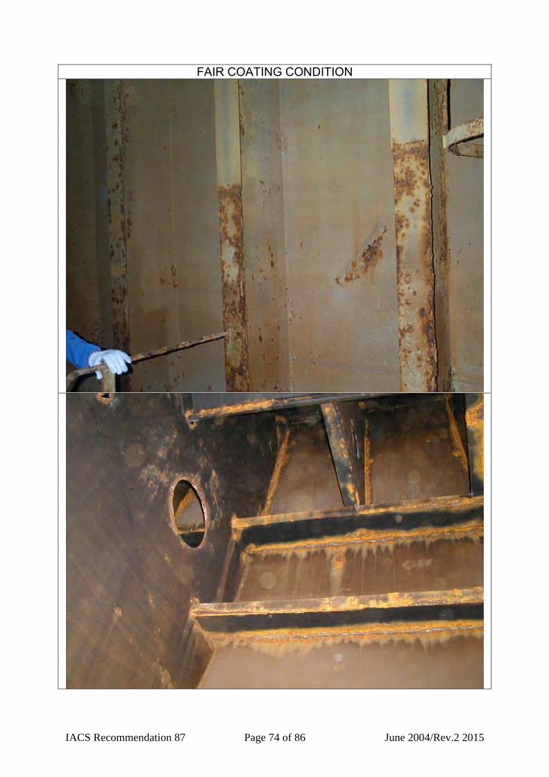
IACS Recommendation 87 Page 74 of 86 June 2004/Rev.2 2015
FAIR COATING CONDITION

IACS Recommendation 87 Page 75 of 86 June 2004/Rev.2 2015
TRANSITION FAIR TO POOR COATING CONDITION: THIS IS A FAIR CONDITION
TRANSITION FAIR TO POOR COATING CONDITION:
THIS IS A FAIR CONDITION

IACS Recommendation 87 Page 76 of 86 June 2004/Rev.2 2015
TRANSITION FAIR TO POOR COATING CONDITION: THIS IS A FAIR CONDITION
TRANSITION FAIR TO POOR COATING CONDITION:
THIS IS A FAIR CONDITION

IACS Recommendation 87 Page 77 of 86 June 2004/Rev.2 2015
TRANSITION FAIR TO POOR COATING CONDITION: THIS IS A POOR CONDITION
TRANSITION FAIR TO POOR COATING CONDITION:
THIS IS A POOR CONDITION
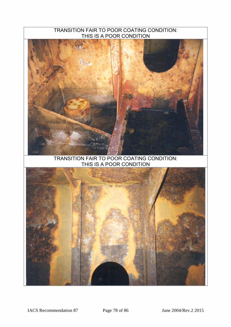
IACS Recommendation 87 Page 78 of 86 June 2004/Rev.2 2015
TRANSITION FAIR TO POOR COATING CONDITION: THIS IS A POOR CONDITION
TRANSITION FAIR TO POOR COATING CONDITION:
THIS IS A POOR CONDITION
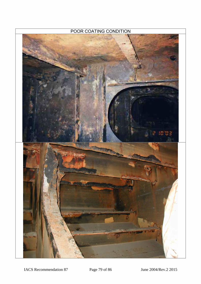
IACS Recommendation 87 Page 79 of 86 June 2004/Rev.2 2015
POOR COATING CONDITION

IACS Recommendation 87 Page 80 of 86 June 2004/Rev.2 2015
POOR COATING CONDITION

IACS Recommendation 87 Page 81 of 86 June 2004/Rev.2 2015
POOR COATING CONDITION

IACS Recommendation 87 Page 82 of 86 June 2004/Rev.2 2015
POOR COATING CONDITION

IACS Recommendation 87 Page 83 of 86 June 2004/Rev.2 2015
POOR COATING CONDITION

IACS Recommendation 87 Page 84 of 86 June 2004/Rev.2 2015
I. Examples of how to report coating conditions with respect to areas under consideration The figure below illustrates how the surveyors may report coating condition in the Executive Hull Summary, Table IX (iv). EXAMPLE 1: Single Hull Tanker No. 3Wing Ballast Tank (P) Tank Protection 1) C
Structure 2) Coating Condition3) Remarks 4)
Areas under consideration Upper Middle Lower
Fore Transverse Bulkhead F G G Aft Transverse Bulkhead F G G Side Shell F F F Longitudinal Bulkhead F G G Deck F Bottom F OVERALL TANK RATING FAIR To be examined at next annual
survey Notes: 1) C: Coating, A: Anodes, NP: No protection 2) The structure includes plating and attached structural members 3) G: Good, F: Fair and P: Poor in accordance with Table II, reproduced herein below 4) Other than “Good” condition, locations and structure members are to be reported. For instance, a case of “Fair” condition. “Fair coating member: upper deck plating Fr No 45 to Fr No 85”
Table II IACS clarification of “GOOD”, “FAIR” and “POOR” coating conditions
GOOD (3) FAIR POOR Breakdown of coating or area rusted (1)
< 3%
3 – 20 %
> 20 %
Area of hard rust scale (1) - < 10 % ≥ 10 % Local breakdown of coating or rust on edges or weld lines (2)
< 20 %
20 – 50 %
> 50 %
Notes (1) % is the percentage of the area under consideration or of the “critical
structural area” (2) % is the percentage of edges or weld lines in the area under consideration
or of the “critical structural area” (3) spot rusting i.e. rusting in spot without visible failure of coating
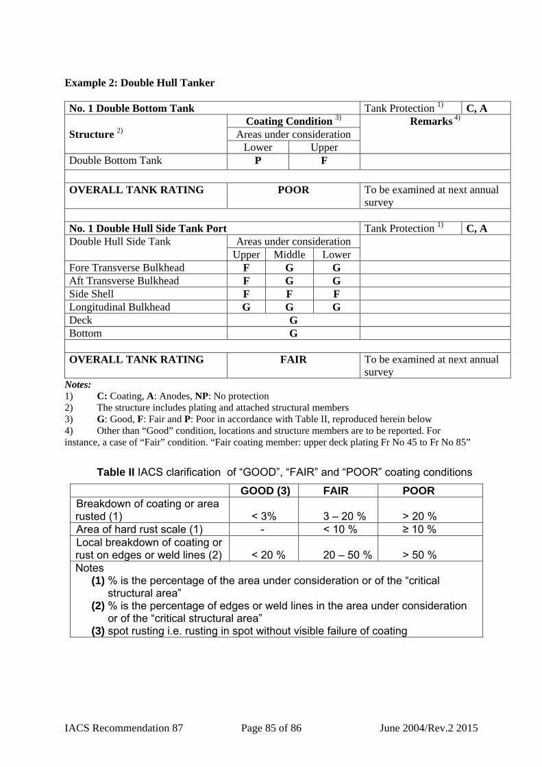
IACS Recommendation 87 Page 85 of 86 June 2004/Rev.2 2015
Example 2: Double Hull Tanker No. 1 Double Bottom Tank Tank Protection 1) C, A
Structure 2) Coating Condition 3) Remarks 4)
Areas under consideration Lower Upper
Double Bottom Tank P F OVERALL TANK RATING POOR To be examined at next annual
survey No. 1 Double Hull Side Tank Port Tank Protection 1) C, A Double Hull Side Tank Areas under consideration
Upper Middle Lower Fore Transverse Bulkhead F G G Aft Transverse Bulkhead F G G Side Shell F F F Longitudinal Bulkhead G G G Deck G Bottom G OVERALL TANK RATING FAIR To be examined at next annual
survey Notes: 1) C: Coating, A: Anodes, NP: No protection 2) The structure includes plating and attached structural members 3) G: Good, F: Fair and P: Poor in accordance with Table II, reproduced herein below 4) Other than “Good” condition, locations and structure members are to be reported. For instance, a case of “Fair” condition. “Fair coating member: upper deck plating Fr No 45 to Fr No 85”
Table II IACS clarification of “GOOD”, “FAIR” and “POOR” coating conditions
GOOD (3) FAIR POOR Breakdown of coating or area rusted (1)
< 3%
3 – 20 %
> 20 %
Area of hard rust scale (1) - < 10 % ≥ 10 % Local breakdown of coating or rust on edges or weld lines (2)
< 20 %
20 – 50 %
> 50 %
Notes (1) % is the percentage of the area under consideration or of the “critical
structural area” (2) % is the percentage of edges or weld lines in the area under consideration
or of the “critical structural area” (3) spot rusting i.e. rusting in spot without visible failure of coating

IACS Recommendation 87 Page 86 of 86 June 2004/Rev.2 2015
Example 3: Fore Peak Tank Fore Peak Tank Protection 1) C
Structure 2) Coating Condition 3) Remarks 4)
Areas under consideration Upper Middle Lower
Fore Peak Tank G G P OVERALL TANK RATING POOR To be examined at next annual
survey Notes: 1) C: Coating, A: Anodes, NP: No protection 2) The structure includes plating and attached structural members 3) G: Good, F: Fair and P: Poor in accordance with Table II, reproduced herein below 4) Other than “Good” condition, locations and structure members are to be reported. For instance, a case of “Fair” condition. “Fair coating member: upper deck plating Fr No 45 to Fr No 85”
Table II IACS clarification of “GOOD”, “FAIR” and “POOR” coating conditions
GOOD (3) FAIR POOR Breakdown of coating or area rusted (1)
< 3%
3 – 20 %
> 20 %
Area of hard rust scale (1) - < 10 % ≥ 10 % Local breakdown of coating or rust on edges or weld lines (2)
< 20 %
20 – 50 %
> 50 %
Notes (1) % is the percentage of the area under consideration or of the “critical
structural area” (2) % is the percentage of edges or weld lines in the area under consideration
or of the “critical structural area” (3) spot rusting i.e. rusting in spot without visible failure of coating