Recirculating Media Filters OWNER'S MANUAL · The second section covers the installation of a...
12
© Copyright 2015. All rights reserved. Model Number: ________________________________________ Job Name: ____________________________________________ Distributor: ____________________________________________ Date of Purchase: ______________________________________ Contractor: ____________________________________________ Date of Installation: ____________________________________ System Readings During Operation: Voltage _____ Amps _____ Congratulations on the purchase of this Clarus Environmental Recirculating Media Filter. This system will provide years of trouble-free service when installed and serviced according to the manufacturer’s recommendations. This manual incorporates the installation, operation, maintenance, and service instructions into one document to aid in the ownership of a Clarus Environmental Onsite Treatment System. Please read and review this manual before installing the product. Follow the steps and procedures listed within for a proper start-up. Many items contained within, when followed correctly, will not only ensure a long and problem-free life for the system, but also save time and money during installation. Should further assistance be necessary, please call Clarus Environmental at 1-800-928-7867. Table of Contents Safety Instructions ....................................................................... 1 Limited Warranty .......................................................................... 2 Troubleshooting & Service Checklist ......................................... 2 Preinstallation Checklist .............................................................. 3 Gravity Discharge System Installation .................................... 4-6 Pump Discharge System Installation ..................................... 7-9 System Start-Up.......................................................................... 10 Operation & Maintenance .......................................................... 11 Safety Instructions TO AVOID SERIOUS OR FATAL PERSONAL INJURY OR MA- JOR PROPERTY DAMAGE, READ AND FOLLOW ALL SAFETY INSTRUCTIONS IN THIS MANUAL AND ON THE PUMP. THIS MANUAL IS INTENDED TO ASSIST IN THE INSTALLATION AND OPERATION OF THIS UNIT AND MUST BE KEPT WITH THE PUMP. This is a SAFETY ALERT SYMBOL. When you see this symbol on the pump or in the manual, look for one of the following signal words and be alert to the potential for personal injury or property damage. Warns of hazards that WILL cause serious personal injury, death or major property damage. Warns of hazards that CAN cause serious personal injury, death or major property damage. Warns of hazards that CAN cause personal injury or property damage. INDICATES SPECIAL INSTRUCTIONS WHICH ARE VERY IMPORTANT AND MUST BE FOLLOWED. THOROUGHLY REVIEW ALL INSTRUCTIONS AND WARNINGS PRIOR TO PERFORMING ANY WORK ON THIS PUMP. MAINTAIN ALL SAFETY DECALS. CAUTION Owner’s Information REFER TO WARRANTY ON PAGE 2. SECTION: C3.20.140 CL0064 0515 Supersedes 1011 Recirculating Media Filters OWNER'S MANUAL Register your Clarus Environmental Product on our website: http://reg.clarusenvironmental.com/ 3649 Cane Run Road • Louisville, KY 40211-1961 800-928-7867 • Fax: 502-774-3624 www.clarusenvironmental.com ® ®
Transcript of Recirculating Media Filters OWNER'S MANUAL · The second section covers the installation of a...

© Copyright 2015. All rights reserved.
Model Number: ________________________________________
Job Name: ____________________________________________
Distributor: ____________________________________________
Date of Purchase: ______________________________________
Contractor: ____________________________________________
Date of Installation: ____________________________________
System Readings During Operation: Voltage _____ Amps _____
Congratulations on the purchase of this Clarus Environmental Recirculating Media Filter. This system will provide years of trouble-free service when installed and serviced according to the manufacturer’s recommendations. This manual incorporates the installation, operation, maintenance, and service instructions into one document to aid in the ownership of a Clarus Environmental Onsite Treatment System. Please read and review
this manual before installing the product. Follow the steps and procedures listed within for a proper start-up. Many items contained within, when followed correctly, will not only ensure a long and problem-free life for the system, but also save time and money during installation. Should further assistance be necessary, please call Clarus Environmental at 1-800-928-7867.
Table of ContentsSafety Instructions ....................................................................... 1
Limited Warranty .......................................................................... 2
Troubleshooting & Service Checklist ......................................... 2
Preinstallation Checklist .............................................................. 3
Gravity Discharge System Installation ....................................4-6
Pump Discharge System Installation .....................................7-9
System Start-Up .......................................................................... 10
Operation & Maintenance .......................................................... 11
Safety InstructionsTO AVOID SERIOUS OR FATAL PERSONAL INJURY OR MA-JOR PROPERTY DAMAGE, READ AND FOLLOW ALL SAFETY INSTRUCTIONS IN THIS MANUAL AND ON THE PUMP.
THIS MANUAL IS INTENDED TO ASSIST IN THE INSTALLATION AND OPERATION OF THIS UNIT AND MUST BE KEPT WITH THE PUMP.
This is a SAFETY ALERT SYMBOL.When you see this symbol on the pump or in the manual, look for one of the following signal words and be alert to the potential for personal injury or property damage.Warns of hazards that WILL cause serious personal injury, death or major property damage.Warns of hazards that CAN cause serious personal injury, death or major property damage.Warns of hazards that CAN cause personal injury or property damage.INDICATES SPECIAL INSTRUCTIONS WHICH ARE VERY IMPORTANT AND MUST BE FOLLOWED.
THOROUGHLY REVIEW ALL INSTRUCTIONS AND WARNINGS PRIOR TO PERFORMING ANY WORK ON THIS PUMP.
MAINTAIN ALL SAFETY DECALS.
CAUTIONOwner’s Information
REFER TO WARRANTY ON PAGE 2.
SECTION: C3.20.140CL0064
0515Supersedes
1011
Recirculating Media Filters
OWNER'S MANUALRegister your
Clarus Environmental Product on our website:
http://reg.clarusenvironmental.com/
3649 Cane Run Road • Louisville, KY 40211-1961800-928-7867 • Fax: 502-774-3624www.clarusenvironmental.com
®®

2© Copyright 2015. All rights reserved.
COMMON CAUSES
System hydraulically overloaded, homeowner inputs too taxing, recirculation device improperly adjusted, pump timer improperly adjusted, poor installation, distribution piping needs cleaning, chemicals have killed the system, not a watertight installation.
Media clogged, underdrain piping clogged, drain system pump not operating, lateral field not operating properly.
Homeowner is not controlling inputs correctly, septic tank needs cleaning, chemicals have killed the system, bad septic tank, poor system management.
Media Filter experiencing a disruption, anaerobic conditions exist, gravel cell flooded, lids not gas- tight, roof vent odor could be confused with filter, system not maintained correctly.
Rodent burrowing or weeds must be removed from system immediately, landscaping not maintained.
Float switch or timer incorrectly set, incorrect or low voltage, pump mechanically bound, defec-tive electrical components, debris on or under float switch(es), check panel fuses and breakers.
Clogged pipe or orifices, timer set incorrectly, increased pipe friction, shut off valve closed, low or incorrect voltage, discharge head exceeds pump capacity, clogged pump strainer, worn out pump.
If the above chart does not uncover the problem, consult Clarus Environmental - Do not attempt to service or otherwise disassemble system or pump.
Troubleshooting and Service Checklist ELECTRICAL PRECAUTIONS- Before servicing a system, always shut off the main power breaker and then disconnect
the pump - making sure you are not standing in water. Wear insulated protective sole shoes. Under flooded conditions, contact your local electric company or a qualified licensed electrician for disconnecting electrical service prior to pump removal.
Limited WarrantyManufacturer warrants, to the purchaser and subsequent owner dur-ing the warranty period, every new product to be free from defects in material and workmanship under normal use and service, when properly used and maintained, for a period of one year from date of purchase by the end user, or 18 months from date of original manu-facture of the product, whichever comes first. Parts that fail within the warranty period, one year from date of purchase by the end user, or 18 months from the date of original manufacture of the product, whichever comes first, that inspections determine to be defective in material or workmanship, will be repaired, replaced or remanufactured at manufacturer's option, provided however, that by so doing we will not be obligated to replace an entire assembly, the entire mechanism or the complete unit. No allowance will be made for shipping charges, damages, labor or other charges that may occur due to product failure, repair or replacement.
This warranty does not apply to and there shall be no warranty for any material or product that has been disassembled without prior ap-proval of manufacturer, subjected to misuse, misapplication, neglect, alteration, accident or act of God; that has not been installed, operated or maintained in accordance with manufacturer's installation instruc-tions; that has been exposed to outside substances including but not limited to the following: sand, gravel, cement, mud, tar, hydrocarbons, hydrocarbon derivatives (oil, gasoline, solvents, etc.), or other abrasive or corrosive substances, wash towels or feminine sanitary products,
etc. in all pumping applications. The warranty set out in the paragraph above is in lieu of all other warranties expressed or implied; and we do not authorize any representative or other person to assume for us any other liability in connection with our products.
Contact manufacturer at, 3649 Cane Run Road, Louisville, Kentucky 40211, Attention: Customer Support Department to obtain any needed repair or replacement of part(s) or additional information pertaining to our warranty.
MANUFACTURER EXPRESSLY DISCLAIMS LIABILITY FOR SPE-CIAL, CONSEQUENTIAL OR INCIDENTAL DAMAGES OR BREACH OF EXPRESSED OR IMPLIED WARRANTY; AND ANY IMPLIED WARRANTY OF FITNESS FOR A PARTICULAR PURPOSE AND OF MERCHANTABILITY SHALL BE LIMITED TO THE DURATION OF THE EXPRESSED WARRANTY.
Some states do not allow limitations on the duration of an implied warranty, so the above limitation may not apply to you. Some states do not allow the exclusion or limitation of incidental or consequential damages, so the above limitation or exclusion may not apply to you.
This warranty gives you specific legal rights and you may also have other rights which vary from state to state.
CONDITION
A. Treatment not as expected
B. Water ponding on surface
C. Effluentfilterclogging frequently
D. Production of odor
E. System aesthetics
F. Pump not operating properly- Alarm condition
G. Pump operates but delivers little or no water
3© Copyright 2015. All rights reserved.
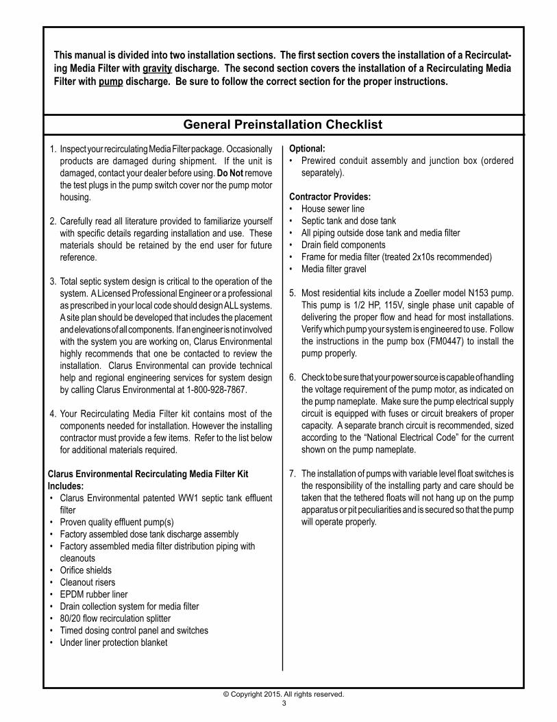
Thismanualisdividedintotwoinstallationsections.ThefirstsectioncoverstheinstallationofaRecirculat-ing Media Filter with gravity discharge. The second section covers the installation of a Recirculating Media Filter with pump discharge. Be sure to follow the correct section for the proper instructions.
General Preinstallation Checklist
1. Inspect your recirculating Media Filter package. Occasionally products are damaged during shipment. If the unit is damaged, contact your dealer before using. Do Not remove the test plugs in the pump switch cover nor the pump motor housing.
2. Carefully read all literature provided to familiarize yourself with specific details regarding installation and use. These materials should be retained by the end user for future reference.
3. Total septic system design is critical to the operation of the system. A Licensed Professional Engineer or a professional as prescribed in your local code should design ALL systems. A site plan should be developed that includes the placement and elevations of all components. If an engineer is not involved with the system you are working on, Clarus Environmental highly recommends that one be contacted to review the installation. Clarus Environmental can provide technical help and regional engineering services for system design by calling Clarus Environmental at 1-800-928-7867.
4. Your Recirculating Media Filter kit contains most of the components needed for installation. However the installing contractor must provide a few items. Refer to the list below for additional materials required.
Clarus Environmental Recirculating Media Filter Kit Includes: • Clarus Environmental patented WW1 septic tank effluent
filter• Proven quality effluent pump(s) • Factory assembled dose tank discharge assembly• Factory assembled media filter distribution piping with cleanouts • Orifice shields • Cleanout risers • EPDM rubber liner • Drain collection system for media filter• 80/20 flow recirculation splitter • Timed dosing control panel and switches • Under liner protection blanket
Optional:• Prewired conduit assembly and junction box (ordered
separately).
Contractor Provides:• House sewer line• Septic tank and dose tank• All piping outside dose tank and media filter• Drain field components• Frame for media filter (treated 2x10s recommended)• Media filter gravel
5. Most residential kits include a Zoeller model N153 pump. This pump is 1/2 HP, 115V, single phase unit capable of delivering the proper flow and head for most installations. Verify which pump your system is engineered to use. Follow the instructions in the pump box (FM0447) to install the pump properly.
6. Check to be sure that your power source is capable of handling the voltage requirement of the pump motor, as indicated on the pump nameplate. Make sure the pump electrical supply circuit is equipped with fuses or circuit breakers of proper capacity. A separate branch circuit is recommended, sized according to the “National Electrical Code” for the current shown on the pump nameplate.
7. The installation of pumps with variable level float switches is the responsibility of the installing party and care should be taken that the tethered floats will not hang up on the pump apparatus or pit peculiarities and is secured so that the pump will operate properly.
4© Copyright 2015. All rights reserved.
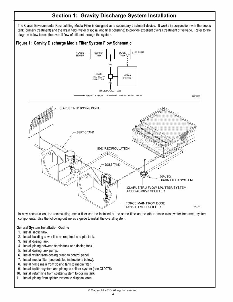
The Clarus Environmental Recirculating Media Filter is designed as a secondary treatment device. It works in conjunction with the septic tank (primary treatment) and the drain field (water disposal and final polishing) to provide excellent overall treatment of sewage. Refer to the diagram below to see the overall flow of effluent through the system.
Section 1: Gravity Discharge System Installation
Figure 1: Gravity Discharge Media Filter System Flow Schematic
In new construction, the recirculating media filter can be installed at the same time as the other onsite wastewater treatment system components. Use the following outline as a guide to install the overall system:
General System Installation Outline 1. Install septic tank. 2. Install building sewer line as required to septic tank. 3. Install dosing tank. 4. Install piping between septic tank and dosing tank. 5. Install dosing tank pump. 6. Install wiring from dosing pump to control panel. 7. Install media filter (see detailed instructions below). 8. Install force main from dosing tank to media filter. 9. Install splitter system and piping to splitter system (see CL0075).10. Install return line from splitter system to dosing tank.11. Install piping from splitter system to disposal area.
SK2097A
HOUSESEWER
TO DISPOSAL FIELD
80%
20%
PRESSURIZED FLOWGRAVITY FLOW
SEPTICTANK
DOSETANK
MEDIAFILTER
80/20TRU-FLOWSPLITTER
N153 PUMP
20% TODRAIN FIELD SYSTEM
CLARUS TRU-FLOW SPLITTER SYSTEMUSED AS 80/20 SPLITTER
80% RECIRCULATION
CLARUS TIMED DOSING PANEL
SEPTIC TANK
DOSE TANK
FORCE MAIN FROM DOSE TANK TO MEDIA FILTER SK2214

5© Copyright 2015. All rights reserved.
Section 1: Clarus Environmental Recirculating Media Filter
Gravity Discharge
SK2160BNOTE: System specific drawing provided with each system.
Figure 2:
ELEVATION VIEW
3/4" PVC PIPE
SEE PIPE SEAL DETAIL
CLARUS 3" ORIFICE SHIELD
PLAN VIEW
TO 80/20 TRU-FLOW SPLITTER
1 1/4" PVC PIPE
4" DRAIN
FROM DOSE TANK
PATIO STONE OVERCLEANOUT AND RISER
17"
14" 13"
15"LINER
FRAME
PIPE FROM PUMP MAYNEED TO BE LARGER
PRESSURE TREATED WOOD OR CONCRETE FRAME(SUPPLIED BY OTHERS)
FILTER MEDIA
NATIVE SOIL MUST BE SMOOTHED, RAKED, COMPACTED, AND LEVELED THROUGHOUT THE LENGTH AND WIDTH
4" BERM (MINIMUM)
PATIO STONE
CLEAN OUT RISER
90° SWEEP ELBOW
4" X 3" PVC RISER MALE NPT ADAPTER & CAP
PROTECTIVE BARRIER
SCREENED VENT
PROTECTIVE BLANKET UNDER45 MIL EPDM RUBBER LINER
8" OF 3/4" TO 1 1/2" DIAMETERUNDER DRAIN MEDIA
24" OF FILTER MEDIA
4" SLOTTED DRAINPIPE
42" MIN.
IN FROM DOSE TANK
TO 80/20 TRU-FLOW SPLITTER
PROTECTIVE BARRIER11" MAXIMUM OF
3/4" - 1 1/2" DIAMETERPEA GRAVEL
1.5"
3"
4" SLOTTEDDRAIN PIPE
SCREENED VENT
PIPE BOOT
ALL STAINLESS PIPE CLAMP
6© Copyright 2015. All rights reserved.
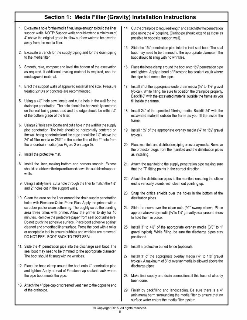
Section 1: Media Filter (Gravity) Installation Instructions
1. Excavate a hole for the media filter, large enough to build the liner support walls. NOTE: Support walls should extend a minimum of 4” above the original grade to allow surface water to be diverted away from the media filter.
2. Excavate a trench for the supply piping and for the drain piping to the media filter.
3. Smooth, rake, compact and level the bottom of the excavation as required. If additional leveling material is required, use the media/gravel material.
4. Erect the support walls of approved material and size. Pressure treated 2x10’s or concrete are recommended.
5. Using a 4½” hole saw, locate and cut a hole in the wall for the drainpipe penetration. The hole should be horizontally centered on the wall being penetrated and the edge should be within ½” of the bottom grade of the filter.
6. Using a 2” hole saw, locate and cut a hole in the wall for the supply pipe penetration. The hole should be horizontally centered on the wall being penetrated and the edge should be 1½” above the 24” of filter media or 26½” to the center line of the 2” hole from the underdrain media (see Figure 2 on page 5).
7. Install the protective mat.
8. Install the liner, making bottom and corners smooth. Excess should be laid over the top and tucked down the outside of support walls.
9. Using a utility knife, cut a hole through the liner to match the 4½” and 2” holes cut in the support walls.
10. Clean the area on the liner around the drain supply penetration holes with Firestone Quick Prime Plus. Apply the primer with a scrubber pad or clean cotton rag. Thoroughly scrub the bonding area three times with primer. Allow the primer to dry for 10 minutes. Remove the protective paper from seal boot adhesive. Do not touch the adhesive surface. Place boot adhesive against cleaned and smoothed liner surface. Press the boot with a roller or acceptable tool to ensure bubbles and wrinkles are removed. DO NOT PEEL BOOT BACK TO TEST SEAL.
11. Slide the 4” penetration pipe into the discharge seal boot. The seal boot may need to be trimmed to the appropriate diameter. The boot should fit snug with no wrinkles.
12. Place the hose clamp around the boot onto 4” penetration pipe and tighten. Apply a bead of Firestone lap sealant caulk where the pipe boot meets the pipe.
13. Attach the 4” pipe cap or screened vent riser to the opposite end of the drainpipe.
14. Cut the drainpipe to required length and attach it to the penetration pipe using the 4” coupling. (Drainpipe should extend as close as possible to opposite support wall).
15. Slide the 1¼” penetration pipe into the inlet seal boot. The seal boot may need to be trimmed to the appropriate diameter. The boot should fit snug with no wrinkles.
16. Place the hose clamp around the boot onto 1¼” penetration pipe and tighten. Apply a bead of Firestone lap sealant caulk where the pipe boot meets the pipe.
17. Install 8” of the appropriate underdrain media (¾” to 1½” gravel typical). While filling, be sure to position the drainpipe properly. Backfill 8” with the excavated material outside the frame as you fill inside the frame.
18. Install 24” of the specified filtering media. Backfill 24” with the excavated material outside the frame as you fill the inside the frame.
19. Install 1½” of the appropriate overlay media (¾” to 1½” gravel
typical).
20. Place manifold and distribution piping on overlay media. Remove the protector plugs from the manifold and the distribution pipes as installing.
21. Attach the manifold to the supply penetration pipe making sure that the “T” fitting points in the correct direction.
22. Attach the distribution pipes to the manifold ensuring the elbow end is vertically plumb, with clean out pointing up.
23. Snap the orifice shields over the holes in the bottom of the distribution pipes.
24. Slide the risers over the clean outs (90° sweep elbow). Place
appropriate overlay media (¾” to 1½” gravel typical) around risers to hold them in place.
25. Install 3” to 4½” of the appropriate overlay media (3/8” to 1” gravel typical). While filling, be sure the discharge pipes stay positioned.
26. Install a protective buried fence (optional).
27. Install 3” of the appropriate overlay media (¾” to 1½” gravel typical). A maximum of 8” of overlay media is allowed above the discharge pipes.
28. Make final supply and drain connections if this has not already been done.
29. Finish by backfilling and landscaping. Be sure there is a 4” (minimum) berm surrounding the media filter to ensure that no surface water enters the media filter system.

7© Copyright 2015. All rights reserved.
The Clarus Environmental Recirculating Media Filter is designed as a secondary treatment device. It works in conjunction with the septic tank (primary treatment) and the drain field (water disposal and final polishing) to provide excellent overall treatment of the onsite effluent. Refer to the diagram below to see the overall flow of effluent through the system.
Section 2: Pump Discharge System Installation
Figure 3: Pump Discharge Media Filter System Flow Schematic
General System Installation Outline 1. Install septic tank. 2. Install drain line as required to septic tank. 3. Install dosing tank. 4. Install piping between septic tank and dosing tank. 5. Install dosing tank pump. 6. Install wiring from dosing pump to control panel. 7. Install media filter (see detailed instructions below). 8. Install force main from dosing tank to media filter. 9. Install media filter pump.10. Install wiring from media filter pump to control panel.11. Install return line from media filter to 80/20 pressure flow splitter.12. Install 80/20 pressure flow splitter at highest point.13. Install return line from 80/20 pressure flow splitter to dose tank.14. Install drain line from 80/20 pressure flow splitter to drain field.
SK2097B
TO DISPOSAL FIELD
HOUSESEWER
20%
80%
PRESSURIZED FLOWGRAVITY FLOW
SEPTICTANK
DOSETANK
MEDIAFILTER80/20
PRESSUREFLOW
SPLITTER W/PUMPDISCHARGE
CLARUS TIMEDDOSING PANEL
80% RECIRCULATION
20% TO DRAINFIELD SYSTEM
80/20PRESSUREFLOWSPLITTER
SEPTIC TANK
DOSE TANK
FORCE MAIN FROM DOSE TANK TO MEDIA FILTER
SK2229
8© Copyright 2015. All rights reserved.
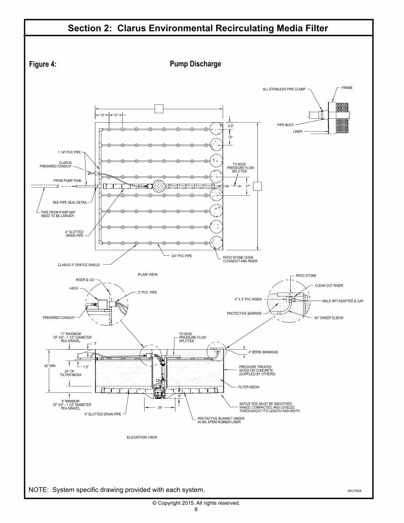
Section 2: Clarus Environmental Recirculating Media Filter
Pump Discharge
SK2160A
Figure 4:
NOTE: System specific drawing provided with each system.
CLARUS 3" ORIFICE SHIELD
PLAN VIEW
6.5"
15"
17"
3/4" PVC PIPE
FROM PUMP TANK
13" 13"
SEE PIPE SEAL DETAIL
PROTECTIVE BLANKET UNDER45 MIL EPDM RUBBER LINER
4" SLOTTED DRAIN PIPE
TO 80/20PRESSURE FLOWSPLITTER
PRESSURE TREATED WOOD OR CONCRETE (SUPPLIED BY OTHERS)
24" OF FILTER MEDIA
11" MAXIMUMOF 3/4" - 1 1/2" DIAMETER
PEA GRAVEL
ELEVATION VIEW
NATIVE SOIL MUST BE SMOOTHED,RAKED, COMPACTED, AND LEVELEDTHROUGHOUT IT'S LENGTH AND WIDTH
1.5"
8" MINIMUMOF 3/4" - 1 1/2" DIAMETER
PEA GRAVEL
FILTER MEDIA
LINER
PIPE BOOT
ALL STAINLESS PIPE CLAMP FRAME
1 1/4" PVC PIPE
24"
6"
PIPE FROM PUMP MAYNEED TO BE LARGER
2" PVC PIPEJ-BOX
PREWIRED CONDUIT
RISER & LID
TO 80/20PRESSURE FLOW
SPLITTER
4" SLOTTEDDRAIN PIPE
CLARUSPREWIRED CONDUIT
PATIO STONE OVERCLEANOUT AND RISER
4" BERM (MINIMUM)
PATIO STONE
PROTECTIVE BARRIER
MALE NPT ADAPTER & CAP4" X 3" PVC RISER
90° SWEEP ELBOW
CLEAN OUT RISER
42" MIN.
3"
9© Copyright 2015. All rights reserved.
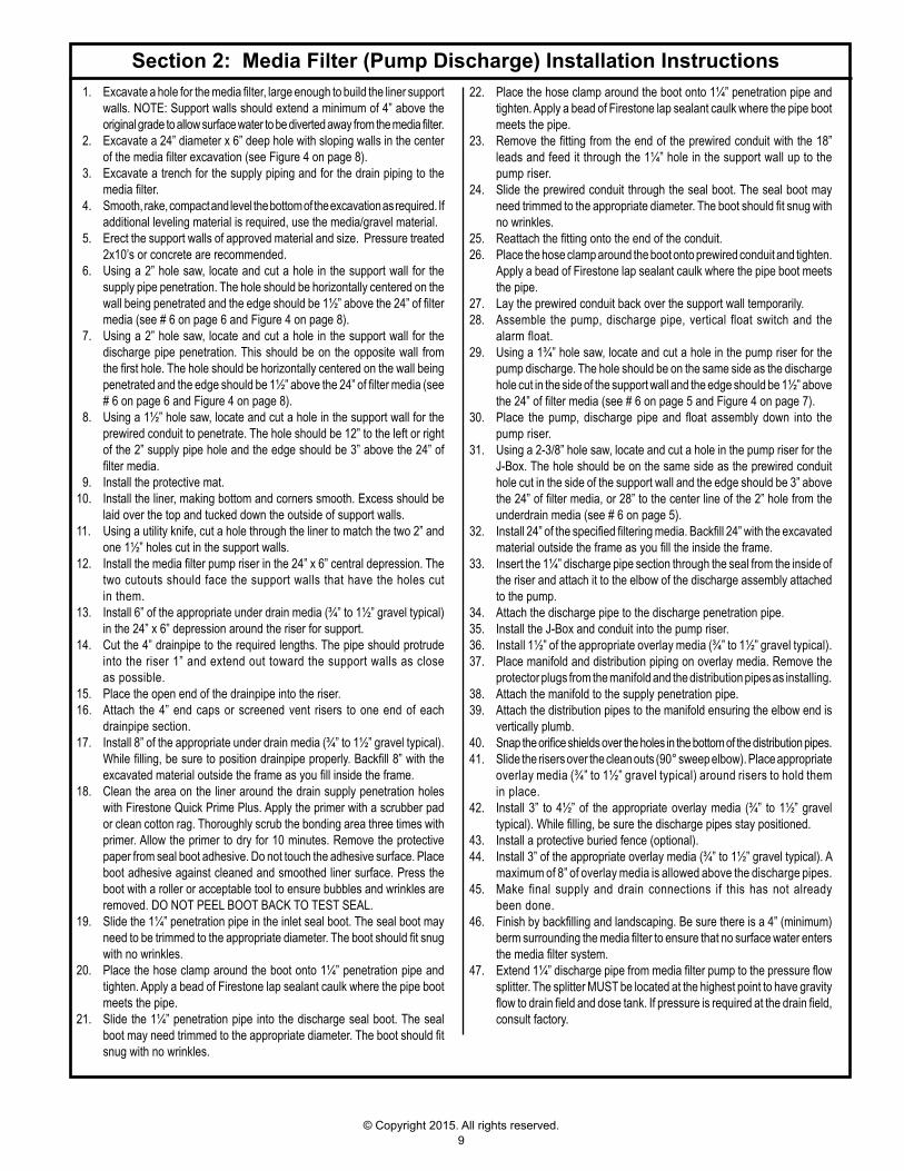
Section 2: Media Filter (Pump Discharge) Installation Instructions 1. Excavate a hole for the media filter, large enough to build the liner support
walls. NOTE: Support walls should extend a minimum of 4” above the original grade to allow surface water to be diverted away from the media filter.
2. Excavate a 24” diameter x 6” deep hole with sloping walls in the center of the media filter excavation (see Figure 4 on page 8).
3. Excavate a trench for the supply piping and for the drain piping to the media filter.
4. Smooth, rake, compact and level the bottom of the excavation as required. If additional leveling material is required, use the media/gravel material.
5. Erect the support walls of approved material and size. Pressure treated 2x10’s or concrete are recommended.
6. Using a 2” hole saw, locate and cut a hole in the support wall for the supply pipe penetration. The hole should be horizontally centered on the wall being penetrated and the edge should be 1½” above the 24” of filter media (see # 6 on page 6 and Figure 4 on page 8).
7. Using a 2” hole saw, locate and cut a hole in the support wall for the discharge pipe penetration. This should be on the opposite wall from the first hole. The hole should be horizontally centered on the wall being penetrated and the edge should be 1½” above the 24” of filter media (see # 6 on page 6 and Figure 4 on page 8).
8. Using a 1½” hole saw, locate and cut a hole in the support wall for the prewired conduit to penetrate. The hole should be 12” to the left or right of the 2” supply pipe hole and the edge should be 3” above the 24” of filter media.
9. Install the protective mat.10. Install the liner, making bottom and corners smooth. Excess should be
laid over the top and tucked down the outside of support walls.11. Using a utility knife, cut a hole through the liner to match the two 2” and
one 1½” holes cut in the support walls.12. Install the media filter pump riser in the 24” x 6” central depression. The
two cutouts should face the support walls that have the holes cut in them.
13. Install 6” of the appropriate under drain media (¾” to 1½” gravel typical) in the 24” x 6” depression around the riser for support.
14. Cut the 4” drainpipe to the required lengths. The pipe should protrude into the riser 1” and extend out toward the support walls as close as possible.
15. Place the open end of the drainpipe into the riser.16. Attach the 4” end caps or screened vent risers to one end of each
drainpipe section.17. Install 8” of the appropriate under drain media (¾” to 1½” gravel typical).
While filling, be sure to position drainpipe properly. Backfill 8” with the excavated material outside the frame as you fill inside the frame.
18. Clean the area on the liner around the drain supply penetration holes with Firestone Quick Prime Plus. Apply the primer with a scrubber pad or clean cotton rag. Thoroughly scrub the bonding area three times with primer. Allow the primer to dry for 10 minutes. Remove the protective paper from seal boot adhesive. Do not touch the adhesive surface. Place boot adhesive against cleaned and smoothed liner surface. Press the boot with a roller or acceptable tool to ensure bubbles and wrinkles are removed. DO NOT PEEL BOOT BACK TO TEST SEAL.
19. Slide the 1¼” penetration pipe in the inlet seal boot. The seal boot may need to be trimmed to the appropriate diameter. The boot should fit snug with no wrinkles.
20. Place the hose clamp around the boot onto 1¼” penetration pipe and tighten. Apply a bead of Firestone lap sealant caulk where the pipe boot meets the pipe.
21. Slide the 1¼” penetration pipe into the discharge seal boot. The seal boot may need trimmed to the appropriate diameter. The boot should fit snug with no wrinkles.
22. Place the hose clamp around the boot onto 1¼” penetration pipe and tighten. Apply a bead of Firestone lap sealant caulk where the pipe boot meets the pipe.
23. Remove the fitting from the end of the prewired conduit with the 18” leads and feed it through the 1¼” hole in the support wall up to the pump riser.
24. Slide the prewired conduit through the seal boot. The seal boot may need trimmed to the appropriate diameter. The boot should fit snug with no wrinkles.
25. Reattach the fitting onto the end of the conduit.26. Place the hose clamp around the boot onto prewired conduit and tighten.
Apply a bead of Firestone lap sealant caulk where the pipe boot meets the pipe.
27. Lay the prewired conduit back over the support wall temporarily.28. Assemble the pump, discharge pipe, vertical float switch and the
alarm float.29. Using a 1¾” hole saw, locate and cut a hole in the pump riser for the
pump discharge. The hole should be on the same side as the discharge hole cut in the side of the support wall and the edge should be 1½” above the 24” of filter media (see # 6 on page 5 and Figure 4 on page 7).
30. Place the pump, discharge pipe and float assembly down into the pump riser.
31. Using a 2-3/8” hole saw, locate and cut a hole in the pump riser for the J-Box. The hole should be on the same side as the prewired conduit hole cut in the side of the support wall and the edge should be 3” above the 24” of filter media, or 28” to the center line of the 2” hole from the underdrain media (see # 6 on page 5).
32. Install 24” of the specified filtering media. Backfill 24” with the excavated material outside the frame as you fill the inside the frame.
33. Insert the 1¼” discharge pipe section through the seal from the inside of the riser and attach it to the elbow of the discharge assembly attached to the pump.
34. Attach the discharge pipe to the discharge penetration pipe.35. Install the J-Box and conduit into the pump riser.36. Install 1½” of the appropriate overlay media (¾” to 1½” gravel typical).37. Place manifold and distribution piping on overlay media. Remove the
protector plugs from the manifold and the distribution pipes as installing.38. Attach the manifold to the supply penetration pipe.39. Attach the distribution pipes to the manifold ensuring the elbow end is
vertically plumb.40. Snap the orifice shields over the holes in the bottom of the distribution pipes.41. Slide the risers over the clean outs (90° sweep elbow). Place appropriate
overlay media (¾” to 1½” gravel typical) around risers to hold them in place.
42. Install 3” to 4½” of the appropriate overlay media (¾” to 1½” gravel typical). While filling, be sure the discharge pipes stay positioned.
43. Install a protective buried fence (optional).44. Install 3” of the appropriate overlay media (¾” to 1½” gravel typical). A
maximum of 8” of overlay media is allowed above the discharge pipes.45. Make final supply and drain connections if this has not already
been done.46. Finish by backfilling and landscaping. Be sure there is a 4” (minimum)
berm surrounding the media filter to ensure that no surface water enters the media filter system.
47. Extend 1¼” discharge pipe from media filter pump to the pressure flow splitter. The splitter MUST be located at the highest point to have gravity flow to drain field and dose tank. If pressure is required at the drain field, consult factory.

10© Copyright 2015. All rights reserved.
LOW LEVEL CUTOUT EVENWITH TOP OF PUMP
TIMER OVERRIDE
HIGH WATER ALARM
15" MIN.
6" MIN.
Performing a good system start-up is crucial to having a long lasting system that will be trouble free. A trained, qualified technician that understands the system’s mechanical and electrical operation must do the system start-up. The system start-up report should be completed in coordination with the installing contractor, start-up technician, health department agent, homeowner, and the engineer. An installation and start-up checklist (CL0141) is included to aid the system start-up procedure.
The timed dosing panel should be set up to dose 96 times per day. Consult the engineering site plan and/or control panel instructions to aid in the set up. Recirculation ratio must be taken into account when adjusting for the daily design flow rate.
The homeowner and maintenance contract personnel must receive a copy of the following documents: 1. Recirculating Media Filter literature sheet (CL0062). 2. Recirculating Media Filter Owner’s Manual (CL0064). 3. Control Panel Wiring Diagram. 4. Control Panel Installation Instructions and Operation/Troubleshooting Manual. 5. Completed Start-Up Report. 6. Tru-Flow® Splitter System Installation Instructions (CL0075). 7. Submersible Pump Installation Instructions (FM0447). 8. WW1 Filter owner's manual (CL0040).
Record the float settings of the dose tank and recirculation basin on the drawings below.
System Start-up
Typical Float Settings For Zoeller Model N153 Pumps
SK2147
MEDIA FILTER DOSE TANK
SK2153
PUMP DISCHARGE BASIN(locatedinmediafilteronpumpdischargesystems)
ON LEVEL
OFF LEVEL
ALARM FLOAT
TETHER HEIGHT
5"
6 1/2"15"
VERTICAL FLOAT SWITCH
TETHER HEIGHT
21"

11© Copyright 2015. All rights reserved.
Your Clarus Environmental Recirculating Media Filter (RMF) is one component of your onsite wastewater system. Your system consists of a primary treatment device (septic tank), secondary treatment device (Clarus Environmental RMF), and a soil distribution component (gravity or pressurized leach lines or a drip field). Your recirculating media filter requires periodic maintenance. Please read the maintenance instructions and be sure that each procedure is accomplished in the proper time frame. These instructions also include guidance for septic tank maintenance. These maintenance procedures should be carried out by a well-trained professional onsite service entity.
Input Inspection ScheduleResidents of every home discharging into an onsite system need to do an annual inspection of inputs to their onsite system. This includes organic (non-water) as well as hydraulic (water use) wastes. Annual home inspection includes:1. Review original “Septic System Do’s and Don’ts”. Note
any changes in household habits and make corrections as needed.
2. Inspect all faucets and toilets in the house and make sure they are not leaking.
Septic Tank Maintenance Procedures and ScheduleEach septic tank requires periodic maintenance. Maintenance includes:1. Inspections need to be done twice annually. Riser cover must
be removed, septic tank must have sludge level recorded and scum layer observations recorded. If the sludge layer is within 12 inches of the bottom of the effluent filter, the tank should be pumped. This will likely be every 3 to 5 years for most homes.
2. Septic tank effluent filter can be removed and cleaned with each septic tank inspection. The Clarus Environmental WW1 Filter (170-0078) filter body is removed and the filtered material held by the filter is rinsed off the filter back into the tank. The outer element which provides bypass protection needs to be cleaned and can be removed after replacing the inner element. Simply withdraw the whole inner and outer element as a unit, which is the reverse of installation. Disassemble on the surface and rinse any filtered material into the septic tank.
3. Inspect all baffles, risers and covers. After inspections, secure riser lid with tamper resistant screws or lock.
Clarus Environmental Recirculating Media Filter Maintenance Procedures and ScheduleEach recirculating media filter requires periodic maintenance. Maintenance includes:1. Annual cleaning of the lateral effluent distribution network. Riser
lids for each lateral (located within the media filter) must be removed and end caps of each lateral located and removed. Each lateral needs to be brushed with a bottlebrush and flushed by manually activating the dosing pump.
2. Any cleanout risers that have been damaged or buried need to be replaced or brought back to grade.
3. Inspect buried horizontal fence material annually. Horizontal fence material must remain in place to prevent surface access to liquid being treated.
4. Weeding may be necessary from time to time.
Clarus Environmental Tru-Flow®Splitter(p/n173-0003)ScheduleEach Clarus Environmental Tru-Flow® Splitter must be annually inspected.1. Remove riser cover and using a flashlight inspect component for
level (using bubble level), 2. Inspect for dirt or scum buildup on splitter. If necessary, flush
with garden hose. 3. Replace cover.
Recirculation Chamber Maintenance Procedures and ScheduleEach recirculating chamber requires periodic maintenance; 3 months after start-up and annually thereafter. 1. The dosing chamber should be inspected annually. Power needs to be shut off at the breaker for this inspection. 2. Riser and lid integrity needs to inspected3. Electrical connections need to be inspected for water and corrosion.
Repairs need to be made when corrosion is found. The use of watertight wire nuts is required.
4. Float control operation needs to be inspected. Any hindrance to float movement must be corrected.
5. Excessive scum and sludge in the pump tank must be removed.
Electrical Components Maintenance Procedures and ScheduleEach electrical component must be inspected annually. 1. Be sure each panel has a wiring diagram included. 2. Inspect panel for corrosion and obvious problems such as water
or odor in the panel.3. Note pump cycle and hour meter readings. These should be
recorded in the panel and in the technicians log. 4. Read voltages and amps and compare to start-up.
With pump power on, float operation must be confirmed. Using a plastic rod, floats can be moved up or down and on/off and alarm switching tested.
Operation and Maintenance

© Copyright 2015. All rights reserved.
All Clarus Environmental products must be installed and maintained in accordance with all applicable codes.Product information presented here reflects conditions at time of publication. Consult factory regarding discrepancies or inconsistencies.
Notes