RecentDevelopments in Schemesof BLDG
6
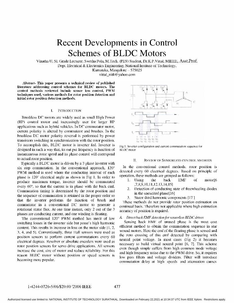
Recent Developments in Control Schemes of BLDG Motors Vinatha U, SI. Grade Lecturer, Swetha Pola, M.Tech. (PES) Student, Dr.K.P.Vittal, MIEEE, Asst.Prof. Dept. Electrical & Electronics Engineering, National Institute of Technology, Karnataka, Mangalore - 575025 [email protected] Abstract- This paper presents a technical review of published literature addressing control schemes for BLDC motors. The control methods reviewed include sensor less control, PWM techniques used, various methods for rotor position detection and - initia rotor position detection methzods. 1.... 7t $§ I. INTRODUCTION Brushless DC motors are widely used as small High Power (HP) control motor and increasingly user for larger HP applications such as hybrid vehicles. In DC commutator motor, current polarity is altered by commutator and brushes. In the X - brushless DC motor polarity reversal is performed by power 1 2 3 4 a transistors switching in synchronization with the rotor position. To accomplish this, BLDC motor is inverter fed. Inverter is Fig. 1. Inverter configuration and current commutation sequence for designed in such a way that, its out put frequency is function of BLDC motor instantaneous rotor speed and its phase control will correspond to actual rotor position. II. REVIEW OF SENSORLESS CONTROL METHODS Typically a BLDC motor is driven by a 3 phase inverter with six step commutation. In the conventional approach, 120° In the conventional control methods, rotor position is PWM method is used where the conducting interval of each detected every 60 electrical degrees. Based on principle of phase is 120° electrical angle as shown in Fig 1. In order to operation, these methods are grouped as follows: produce maximum torque, inverter should be commutated 1. Using the back EMF of motor[6 every 60°, so that the current is in phase with the back emf. ,7,8,9,10,11,12,13,14,15] Commutation timing is determe by t2. Detection of conducting state of freewheeling diodes CommTlutation timing iS determined by the rotor position andanteuecie ae1 the sequence of commutation is retained in the proper order so p that the inverter performs the function of brush and 3. Stator third harmonic components [17 These methods do not provide rotor position estimation on cotmmutator inua c tiona DC motor to te a continual basis. Therefore not applicable where high estimation rotational stator flux. At one time instant, only 2 out of the 3 accuracy of position is required. phases are conducting current, and one winding is floating. The conventional 120° PWM method has merit of low A. Direct back EMF detection for sensorless BLDC drives switching losses in the inverter side but posse's high harmonic Sensing back EMF of unused phase is the most cost content. This results in increase in loss on the motor side [1, 2 efficient method to obtain the commutation sequence in star 3, 4, and 5]. Conventionally, three Hall sensors were used as wound motors. Here the emf of the floating phase is sensed and position sensors to perform current commutations every 60 the zero crossing of this emf detected by comparing with electrical degrees. Resolver or absolute encoders were used as neutral point voltage. In most cases (Fig 2) it becomes rotor position sensors for servo drive applications. All sensors necessary to build virtual neutral point [6, 7]. This scheme increase the cost, size of motor and reduce reliability. For this even though simple suffers from high common mode voltage and high frequency noise due to the PWM drive. So, it requires reason BLDC motor without position or speed sensors is lo pasflesadvlaedvdr. Fitrwl.nrdc becoming more popular. ~~~colmmutation delay at high speeds and attenuation causes 1-4244-0726-5/06/$20.OO '2006 IEEE 477 Authorized licensed use limited to: NATIONAL INSTITUTE OF TECHNOLOGY SURATHKAL. Downloaded on February 22,2021 at 10:34:37 UTC from IEEE Xplore. Restrictions apply.
Transcript of RecentDevelopments in Schemesof BLDG
Recent Developments in ControlSchemes of BLDG Motors
Vinatha U, SI. Grade Lecturer, Swetha Pola, M.Tech. (PES) Student, Dr.K.P.Vittal, MIEEE, Asst.Prof.Dept. Electrical & Electronics Engineering, National Institute of Technology,
Karnataka, Mangalore - [email protected]
Abstract- This paper presents a technical review of publishedliterature addressing control schemes for BLDC motors. Thecontrol methods reviewed include sensor less control, PWMtechniques used, various methods for rotor position detection and -initia rotor position detection methzods. 1.... 7t $§
I. INTRODUCTION
Brushless DC motors are widely used as small High Power(HP) control motor and increasingly user for larger HPapplications such as hybrid vehicles. In DC commutator motor,current polarity is altered by commutator and brushes. In the X -brushless DC motor polarity reversal is performed by power 1 2 3 4 a
transistors switching in synchronization with the rotor position.To accomplish this, BLDC motor is inverter fed. Inverter is Fig. 1. Inverter configuration and current commutation sequence for
designed in such a way that, its out put frequency is function of BLDC motorinstantaneous rotor speed and its phase control will correspondto actual rotor position. II. REVIEW OF SENSORLESS CONTROL METHODS
Typically a BLDC motor is driven by a 3 phase inverter withsix step commutation. In the conventional approach, 120° In the conventional control methods, rotor position isPWM method is used where the conducting interval of each detected every 60 electrical degrees. Based on principle ofphase is 120° electrical angle as shown in Fig 1. In order to operation, these methods are grouped as follows:produce maximum torque, inverter should be commutated 1. Using the back EMF of motor[6every 60°, so that the current is in phase with the back emf. ,7,8,9,10,11,12,13,14,15]
Commutation timing is determe by t2. Detection of conducting state of freewheeling diodesCommTlutation timing iS determined by the rotor position andanteuecie ae1the sequence of commutation is retained in the proper order so pthat the inverter performs the function of brush and 3. Stator third harmonic components [17
These methods do not provide rotor position estimation oncotmmutator inua c tiona DC motor to te a continual basis. Therefore not applicable where high estimationrotational stator flux. At one time instant, only 2 out of the 3 accuracy of position is required.phases are conducting current, and one winding is floating.
The conventional 120° PWM method has merit of low A. Direct backEMFdetectionfor sensorless BLDC drivesswitching losses in the inverter side but posse's high harmonic Sensing back EMF of unused phase is the most costcontent. This results in increase in loss on the motor side [1, 2 efficient method to obtain the commutation sequence in star3, 4, and 5]. Conventionally, three Hall sensors were used as wound motors. Here the emf of the floating phase is sensed andposition sensors to perform current commutations every 60 the zero crossing of this emf detected by comparing withelectrical degrees. Resolver or absolute encoders were used as neutral point voltage. In most cases (Fig 2) it becomesrotor position sensors for servo drive applications. All sensors necessary to build virtual neutral point [6, 7]. This schemeincrease the cost, size of motor and reduce reliability. For this even though simple suffers from high common mode voltage
and high frequency noise due to the PWM drive. So, it requiresreason BLDC motor without position or speed sensors is lo pasflesadvlaedvdr. Fitrwl.nrdcbecoming morepopular. ~~~colmmutation delay at high speeds and attenuation causes
1-4244-0726-5/06/$20.OO '2006 IEEE 477
Authorized licensed use limited to: NATIONAL INSTITUTE OF TECHNOLOGY SURATHKAL. Downloaded on February 22,2021 at 10:34:37 UTC from IEEE Xplore. Restrictions apply.

Vdc
N
VL
GNIl
Fig 4 .Winding terminal voltage during PWM off time
POVVER GNDLk=H SM jey e R Fig 4 shows a particular stage where phase A and B are
virt ma I divd &N rt conducting and phase C floating. Upper switch A is pulsewidth modulated and lower switch of phase B is on during the
Fig 2 .Back EMF sensing based on virtual neutralpoint entire step, switched only at commutation. When upper switchreduction in signal sensitivity at low speeds. Consequently of phase A is turned off current freewheels through the diode.speed range is narrowed. In order to reduce switching noise Neglecting forward voltage drop across the diode for the phaseback EMF integration and third harmonic integration methods A and voltage drop across the device for phase B we can getare used [9] Also Various PWM techniques are developed. Vl=ec+Vn=ec(3I2).During PWM off time terminal voltage of
1) PWM technique which eliminates virtual neutral point the floating phase Vc is proportional to back EMF ec with someJianwen Shao et.al [6] and T.Endo et...al. [8] have presented gain without any superimposed switching noise. Also terminal
a back EMF sensing method which does not require a virtualvotgisrfretoruniseaofetalpn.neutral point and large amount of filtering. Here the zero As a result there are no common mode voltage issues. sincecrossing of emf of floating phase is obtained by properly true back emf is extracted from the terminal voltage zeroselecting the PWM and sensing strategy. In the scheme crossing of the back EMF can be detected very precisely.proposed by Jianwen Shao et.al [6] PWM signal is applied on Resulting signal is not attenuated or filtered and there byhigh side switches only, low side switches are only switched to provides a signal with good signal/noise ratio. This schemeprovide commutation as in Fig 3. At any instant one phase is provides a much wider speed range.driven with PWM high side switch and another phase is driven
2 W ehiu tlwsedapiainwith the low side switch. Remaining phase is open. Back emf 2 t lowspteadg applicastheon dropfo thes
ofcoEnMpasisndegrtecte durngPWMrhroffc timte.goro olaeapiationstheosA n voltage drop acrossthedeiefrpaeBwcngt
areopen phas.Also Various P offtechnique.are developed. body diode of the MOSFET's will affect the performance.When the motor speed goes low, zero crossing is not evenlydistri uted. If the spee goes further low, the back emf
'A amplitude becomes too low to detect. Two methods to correctAelecting the PWM andsensingstrategy.Inthescheme the offset voltage of back EMF signal are presented by Jianwen
Shao et al. [1i]. First method is to use complementary PWM asshown in Fig 5. This also reduces the conduction loss. Anothermethod to eliminate the effect of diode voltage drop is to add a
threshold voltage for zero crossing detection. PreconditioningC circuits for low speed applications is also presented in [10],
which not only compensates the offset voltage caused bydiodes but also amplifies the signal of back EMF near zerocrossing.
A A(-" 3 A C 3) Improved Direct backEMF detection schemeJianwen Shao et al. [11] have proposed an improved direct
back EMF detection for sensorless control of BLDC motor.Fig.3. PWM applied to high side switches only
478
Authorized licensed use limited to: NATIONAL INSTITUTE OF TECHNOLOGY SURATHKAL. Downloaded on February 22,2021 at 10:34:37 UTC from IEEE Xplore. Restrictions apply.

0~~~~~~~~~~~~~~III
Mt
AB AC BC BA CA CB WAf 60 120l( S 240 300 360
Fig 5 Complementary PWM algorithmvic Fig7 PWM scheme which reduces power loss
Va However as the low side device is on , output terminal isconnected to the negative dc link. For other two phases the
79Vn # control signals are applied with 120°shift.
5) ImprovedPWM techniquefor smallpower applicationsvc The significant heat loss that is produced due to the current
- flowing through the anti parallel diode during the period when
ONDthe switch is with chopper control(Fig 7) is reduced in anotherPWM technique given in [13]. In this PWM technique high
Fig 6 .Winding terminal voltage during PWM ontime side switch is chopped in 1/6 fundamental frequency andclamped to DC link for in the next 1/6 fundamental frequency
This scheme eliminates the limitation of back EMF detection as shown in Fig 8 .
during PWM off time. That is, it cannot go up to 100% duty During the period when high side device is with choppercycle since minimum off time is needed to have a time window control the associated low side switch is triggered by inverseto detect back emf. Here back EMF is detected during PWM signal of chopper control. The on state of low side poweron time for some applications where 100% duty ratio is device indicates that the output terminal is connected tonecessary. At lower speed, back EMF detection is done during negative dc link rather than the positive. The low side poweroff time. Fig 6 shows the winding terminal voltage during switch is also controlled in a similar manner. When it is withPWM on time when phase A and B are conducting current and chopper control, the associated high side switch is triggered byphase C is floating. Under this condition terminal voltage of inverse signal of chopper control signal. For the other twoopen phase C is Vc= ec (3/2) +Vdc/2. Comparing Vc with Vdc/2 phases control signals are applied with 120° phase shift. Withgives zero crossing of back emf ec .Thus duty cycle limitation this technique, voltage drop caused by the turn on resistance ofcan be overcome by synchronously detecting the back EMF power device and the load current, is significantly reduced asduring the PWM on time. compared to forward voltage drop of diode. Hence results in
reduction in power consumption and method is promising for4) PWM techniquefor smallpower applicationssmlpoeapictn.A novel PWM technique for small power BLDC motor r al
drives which reduces the conduction losses and in turn reduces B. DSP based Sensorless controlfor high speed applicationsheat dissipation presented in [12,13]. For small power Based on the method of executing the PWM control,applications of BLDC drives power consumption reduction is schemes are classified as uni polar and bipolar switchingthe main objective because of the use of battery and limited schemes. In uni polar switching method PWM is applied to onespace for heat dissipation. In the PWM technique presented by of the two active switches in on state while the other switchYen-Shin Lai et al. [12] the high side power device is chopped remains ON state [6, 10]. In bipolar switching scheme both thein 1/6 fundamental period, duty ratio is derived from the speed active switches are applied with PWM at the same time [7, 8,reference or error of speed. For the next 1/6 fundamental 12, 13, and 14]. Unipolar switching scheme has the advantageperiod, it is clamped to positive dc link for both intervals of of reduced switching loss. Unipolar switching is furtherhigh side device, the associated low side device is off as shown classified into on going phase PWM, off going phase PWM,in Fig 7. Similar control signals are given to low side devices upper switch PWM, lower switch PWM schemes.with 180° shift.
479
Authorized licensed use limited to: NATIONAL INSTITUTE OF TECHNOLOGY SURATHKAL. Downloaded on February 22,2021 at 10:34:37 UTC from IEEE Xplore. Restrictions apply.

..t .p o i;gd-fi
P\VNI tWitchihg 0ri6d interruipt
K~~~~~~~~~~~~~~~~~~~~6) 120 1 . 240 300 360
Fig 8 PWM4 scheme promising for low power applications C(fiffidta on signral iriterfuptkNext nvreseqer c
In the on going switch PWM scheme each switch executes c ao d6lotjthe PWM during the first 60 degrees of active interval and held )on during the second 60 degrees of interval [13]. In the offgoing PWM each active switch is held on during the first 60 Fig.9. Relation between the PWM4 switching period and commutating instantdegrees of active interval and applied with PWM in the next 60 (a) Ideal commutation.(b)Case of commutation delaydegrees [16]. In the upper switch PWM scheme, PWM is givento upper one of the two active switches and in the lower switchChpePWM vise versa [6, 10].Depending on the PWM method used, the control scheme
may cause a commutation delay in high speed applications,since the PWM switching and the inverter commutation cannotbe done independently. If the commutating instant is I BLDCMgt:rsynchronized with the end of the PWM switching period, ideal i
commutation occurs with out any delay. But, since thecommutating instant depends on the rotor position, it does notgenerally coincide with the end of PWM period. In such casesundesirable commutation delay is produced, if thecommutation is performed with the end of the present PWM FglCrutcniuainfraD ikvlaecnrlshmperiod as shown in Fig 9. One way of avoidin this delay is to
terminate the present PWM period and synchronize a new Commutation signals and actual speed are obtained using thePWM period with the commutation instant. But this may cause sensed back EMF by means of integration and comparisonan irregular switching frequency in upper and lower switch circuits. Using a digital PI controller and the calculated valuePWM schemes. In on going and off going phase PWM of speed, duty ratio of chopper is controlled With this twoschemes this method can be used for high speed sensorless phase PWM method can be used even in high speed regioncontrol. However, only few pulses of PWM can be used for without any commutation delay.speed control during a 60 degree interval in high speed range.Commutation delay can be reduced by increasing the PWM Microprocessor ase sensors cjontrollersrswitching frequency. But there is a practical limitation on the Mioroproers.dandcoua paing major reins buldintheswitching frequency due to the increased switching losses, controlrs in [1] ada controltschemesenfr sfesos c
sofay
switching frequency of commercially available power devices BLDC motyo is preenedEhihoeqirshaeEFoenis less than 20 kllz. These problems are over come by from oinalyoensedofthedEM inof3nphasegmotor.a hw i i
controlling the voltage and frequency independently by DC The singnansd istfeduint aninegra a shon in Fign 1link voltage control scheme. for fiter ando inrung neecsry .The thoduesi isA DSP based high speed sensorless control scheme using a fed ttioz cin g fdaettor wch produces two
DC link voltage control is presented by Kyeong-Hwa Kim et al I[14]. ere the, inverter is supplied with a square wave of 1M pass filter is used to extract the phase information from the
degree c ondutn intervaW hOseanfrqency. is cotrlled an bakEFa inFIg12 sInc an idea integrato cano beusdspeed cotroln insotainteendsbyreuatntheDCtooiionk votagoes nof In tha cas phs dea inrdue bythe fite vaiewthth
th nvetrsoni i 0fd from tastepiown chpe. mtrsedelan has todbecorced infre tohroue corcRommtorpstion in eformatio wishdthetendusin the backenEM. cmuainPiigWhMupu fzr rssn eetri
480 OCrutcofgrhnfra Cln otgecnrlshm
Authorized licensed use limited to: NATIONAL INSTITUTE OF TECHNOLOGY SURATHKAL. Downloaded on February 22,2021 at 10:34:37 UTC from IEEE Xplore. Restrictions apply.
IV. INDIRECT BACK EMF DETECTION BY DETECTING THECONDUCTING STATE OF FREE WHEELING DIODES
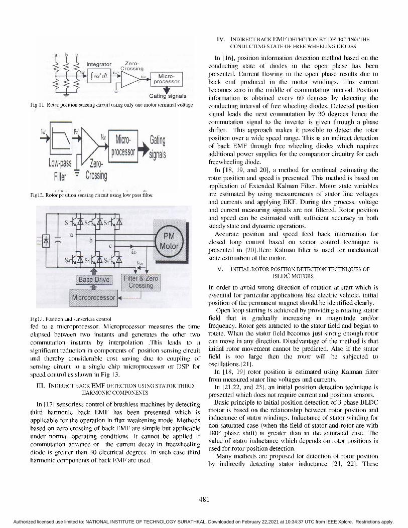
b In [16], position information detection method based on theIntegrator Zero-
Crossing conducting state of diodes in the open phase has beend Micro r =presented. Current flowing in the open phase results due toSa S~~~~~~m cfo~
>- _ processor back emf produced in the motor windings. This currentbecomes zero in the middle of commutating interval. Position
G-ting signals information is obtained every 60 degrees by detecting theFig 11 Rotor position sensing circuit using only one motor terminal voltage conducting interval of free wheeling diodes. Detected position
signal leads the next commutation by 30 degrees hence thecommutation signal to the inverter is given through a phase
Vaf VaH \shifter. This approach makes it possible to detect the rotor4 Mc position over a wide speed range. This is an indirect detection
of back EMF through free wheeling diodes which requiresprocessorf sinals additional power supplies for the comparator circuitry for each
Low pass E Zzero= freewheeling diode.-of p PIn [18, 19, and 20], a method for continual estimating the
Filter Crossing rotor position and speed is presented. This method is based onapplication of Extended Kalman Filter. Motor state variables
Figl2. Rotor position sensing circuit using low pass filter are estimated by using measurements of stator line voltagesand currents and applying EKF. During this process, voltageand current measuring signals are not filtered. Rotor positionand speed can be estimated with sufficient accuracy in bothsteady state and dynamic operations.
PM Accurate position and speed feed back information for_ |~~~~~~~~~~~~~~~~~~~ition in orm ion or W,9s
gl mV l> iI | closed loop control based on vector control technique ispresented in [20].Here Kalman filter is used for mechanicalstate estimation of the motor.
V. INITIAL ROTOR POSITION DETECTION TECHNIQUES OFBLDC MOTORS
In order to avoiwrndietoofrttoatsrthchsessential or particular applications like electric vehicle, iniial
_ ~~~~~~~~~~~~positionof the permanent magnet should be identified clearly.Open loop starting is achieved by providing a rotating stator
Figl3. Position and sensorless control field that is gradually increasing in magnitude and/orfed to a microprocessor. Microprocessor measures the time frequency. Rotor gets attracted to the stator field and begins toelapsed between two instants and generates the other two rotate. When the stator field becomes just strong enough rotorcommutation instants by interpolation This leads to a can move in any direction. Disadvantage of the method is thatsignificant reduction in components of position sensing circuit initial rotor movement cannot be predicted. Also if the statorand thereby considerable cost saving due to coupling of field is too large then the rotor will be subjected tosensing circuit to a single chip microprocessor or DSP for oscillations. [21].speed control as shown in Fig 13. In [18, 19] rotor position is estimated using Kalman filter
from measured stator line voltages and currents.III. INDIRECT BACK EMF DETECTION USING STATOR THIRD In [21,22, and 23], an initial position detection technique is
HARMONIC COMPONENTS presented which does not require current and position sensors.In [17] sensorless control of brushless machines by detecting Basic principle to initial position detection of 3 phase BLDC
third harmonic back EMF has been presented which is motor is based on the relationship between rotor position andapplicable for the operation in flux weakening mode. Methods inductance of stator windings. Inductance of stator winding forbased on zero crossing of back EMF are simple but applicable non saturated case (when the field of stator and rotor are withunder normal operating conditions. It cannot be applied if 180° phase shift) is greater than in the saturated case. The
om ttnnin fre eling value of stator inductance which depends on rotor positions iscolmmutation advance or the current decay use forweenroo .osto. etcindiode is greater than 30 electrical degrees. In such case third Man mehd ar.rpsdfrdtcto frtrpsto
harmonccompnents f backEMF ar used.by indirectly detecting stator inductance [21, 22]. These
481
Authorized licensed use limited to: NATIONAL INSTITUTE OF TECHNOLOGY SURATHKAL. Downloaded on February 22,2021 at 10:34:37 UTC from IEEE Xplore. Restrictions apply.

include detecting peak value of stator currents, and may beclassified as, [8] Jianwen Shao, Member,IEEE, Dennis Nolan and Thomas Hopkins, "A
i. Current after excitation: Where stator windings novel Direct Back EMF Detection for Sensorless Brushless DC(BLDC)are xcitd foa sort erio les tha -c f sttor
Motor Drives,"in Proc. IEEE APEC,2002.are excited for a short period less than x of stator [9] Becerra R C. , Jahns, T.M. , and Ehsani,M , "Four -quadrant sensorlesscircuit. Peak value for saturated case greater than brushless ECM drive", IEEE Applied Power Electronics Conference andfor unsaturated case. Exposition, 1991
ii. Detecting current magnitude: Magnitude of stator [10] Jianwen Shao, Member, IEEE, Dennis Nolan and Thomas Hopkins,"Improved Direct Back EMF Detection for Sensorless Brushless DC
currents are sensed for a given time after (BLDC) Motor Drives," IEEE 2003excitation, with different excitation. Current for [11] Jianwen Shao, Member, IEEE, Dennis Nolan, "Further Improvement ofsaturated case is greater than linear case. Direct Back EMF Detection for Sensorless Brushless DC(BLDC) Motoriii. Detcting rse timeof statr windig after Drives," IEEE 2005.
iii. Detecting rise time of stator winding after [12] Yen-Shin Lai, Fu-San Shyu, Yung- Hsin Chang, "Novel Pulse-Widthexcitation: here step voltage is applied to stator Modulation Technique With Loss Reduction For Small Power Brushlessand rise time is detected which is similar for dc Motor Drives", Industry Applications Conference, 2002. Conferenceunsaturated case than linear case. For above Record of the 37th IAS Annual Meeting, Vol. 3, 13-18 Pages: 2057 - 2064
Oct. 2002.three approaches initial position is identified [13] Yen-Shin Lai, Fu-San Shyu, Yung- Hsin Chang, "Novel loss reductionusing 6 different excitation configurations by Pulse-Width Modulation Technique For Brushless dc Motor Drives Fedcomparing peak, magnitude or response speed of by Mosfet Inverter", IEEE Transactions On Power Electronics, Vol. 19,
current associted wih the eciting ignal. No. 6, Nov. 2004.currents associated with the exciting signal. [14] Kyeong-Hwa Kim and Myung-Joong Youn, "DSP-Based High-SpeedThese approaches do not require current sensors Sensorless Control for a Brushless DC Motor Using a DC Link Voltageor position sensors. Control",Electric Power ComponentAnd Systems,30:889-906,2002.
iv. Detecting falling time of stator winding after [15] Gui-Jia Su and John W.Keever, "Low Cost Sensorless Control OfBrushless DC Motors with Improved Speed Range", IEEE 2002.
removing excitation signal: Here falling time of [16] Satoshi Ogasawara and Hirofumi Akagi, "An Approach to Positioncurrent is detected which is greater for saturation Sensorless Drive for Brushless DC Motors,"IEEE Trans On Industrycase than linear case. Applications, Vol. 27, No. 5. SEP/OCT 1991.
In [22, 23], initial position is identified by measuring the [17] J.X.Shen,Z.Q.Zhu and David Howe, "Sensorless Flux-Weakening ControlOf Permanent-Magnet Brushless Machines Using Third Harmonic Back
period of falling time of stator windings instead of using falling EMF", IEEE Transactions On Industrial Electronics, Vol. 40, No. 6,times. Period of falling time for linear case is greater than Nov/Dec 2004.saturated case because large inductance stores more electrical [18] R.Dhaouadi, N Mohan, and L.Klepsch, "Design and Implementation of
the Extended Kalman Filter for the Speed and Rotor Position Estimationenergy and increases the falling time of discharge after the of Brushless DC Motor", IEEE Transactions on Power Electronics, Vol.excitation signal is removed. This result in a larger 48, No. 6, July 1991.freewheeling period for the associated winding during the [19] Bozo Terzic and Martin Jadric, "Design and Implementation of thedischarge process therefore terminal voltages across the Extended Kalman Filter for the Speed and Rotor Position Estimation of
Brushless DC Motor", IEEE Transactions On Industrial Electronics,windings are measured instead of current for identifying the Vol. 48, No. 6, December 2001.rotor initial position. [20] Mihai Cemat,Vasile Comnac, Radu-Marian Cemat and Maria Cotorogea,
"Sensorless Control of Interior Permanent Magnet Synchronous MachineVI. CONCLUSION Using a Kalman Filter",IEEE 2000.
[21] James P.Johnson,M.Ehsani and Yilchan Guzelgunler, "Review OfA review of sensorless control of BLDC motors is presented Sensorless Methods for Brushless DC",IEEE 1999
and their important features are discussed. Methods of [22] Yen-Shin Lai, Fu-San Shyu, and Shian Shau Tseng, "New Initial Positiondetecting initial rotor position are also presented in an effort to Detection technique for Three-Phase Brushless DC Motor Without
Position and Current Sensors", IEEE Transactions On Industryprovide reference for utilizing these methods. Applications, Vol. 39, No. 2, March/April 2003.
REFERENCES [23] Yen-Shin Lai, Fu-San Shyu, and Shian Shau Tseng, "A Novel startingmethod of sensorless salient pole brushless motor',Conf Record IEEE,
[1] Krishnan R ,Motor drives modeling analysis and control, prentice hall of Vol. 1, No. 2, October 1994India 2002.
[2] Krishnan, R. Lee, S, "PM Brushless dc Motor Drive With A New Power-Converter Topology", IEEE Transactions on Industry Applications, Vol.33 , Issue: 4 pages 973 - 982, July-Aug. 1997
[3] Byoung-Kuk Lee, Tae-Hyung Kim, and Mehrdad Ehsani," On theFeasibility of Four-Switch Three-Phase BLDC Motor Drives for LowCost Commercial Applications: Topology and Control", IEEETransactions On Power Electronics, Vol. 18, No. 1, Jan 2003.
[4] Bimbra.P.S, "Power Electronics"[5] Rahul Khopkar,S . M.Madan,Masoud HaJiaghajani and Hamid A.
Toliyat, "A Low-Cost BLDC Motor Drive using Buck-Boost converterfor Residential and Commercial Applications",IEEE 2003.
[6] Jianwen Shao, Member, IEEE, Dennis Nolan, MaximeTeissier, andDavid Swanson, "A Novel Microcontroller-Based Sensorless BrushlessDC (BLDC) Motor Drive for Automotive Fuel Pumps," IEEETrans.Ind.Applic., vol.39, NO.6, NOV/DEC 2003.
[7] T .Endo and F.Tajima, "Microcomputer controlled brushless motorwithout a shaft mounted position sensor", in Proc IPEC-Tokyo, 1983.
482
Authorized licensed use limited to: NATIONAL INSTITUTE OF TECHNOLOGY SURATHKAL. Downloaded on February 22,2021 at 10:34:37 UTC from IEEE Xplore. Restrictions apply.