Recent Manufacturing Advances . for Spiral Bevel · PDF fileRecent Manufacturing Advances ....
14
AD-A242 526 NASA AVSCOM Technical Memorandum 104479 Technical Report 91-C-022 Recent Manufacturing Advances . for Spiral Bevel Gears Robert F. Handschuh and Robert C. Bill Propulsion Directorate U.S. Army Aviation Systems Command Lewis Research Center Cleveland, Ohio Prepared for the Aerotech '91 sponsored by the Society of Automotive Engineers Long Beach, California, September 23-26, 1991 ":;'•' l.n IJz•r:!itnIUS ARM AVIAMiN .. .... .. .... A.U A SYSTEMS COMMAND 91-14966 91 1104 OA&
Transcript of Recent Manufacturing Advances . for Spiral Bevel · PDF fileRecent Manufacturing Advances ....
AD-A242 526
NASA AVSCOMTechnical Memorandum 104479 Technical Report 91-C-022
Recent Manufacturing Advances .for Spiral Bevel Gears
Robert F. Handschuh and Robert C. BillPropulsion DirectorateU.S. Army Aviation Systems CommandLewis Research CenterCleveland, Ohio
Prepared for theAerotech '91sponsored by the Society of Automotive Engineers
Long Beach, California, September 23-26, 1991
":;'•' l.n IJz•r:!itnIUS ARMAVIAMiN.. ... . .. ....A.U ASYSTEMS COMMAND
91-14966 91 1104 OA&
s t'
RECENT MANUFACTURING ADVANCES FOR SPIRAL BEVEL GEARS' ' ,
Robert F. Handschuh and Robert C. Bill T- 'orPropulsion Directorate *fimt
U.S. Army Aviation Systems CommandLewis Research CenterCleveland, Ohio 44135
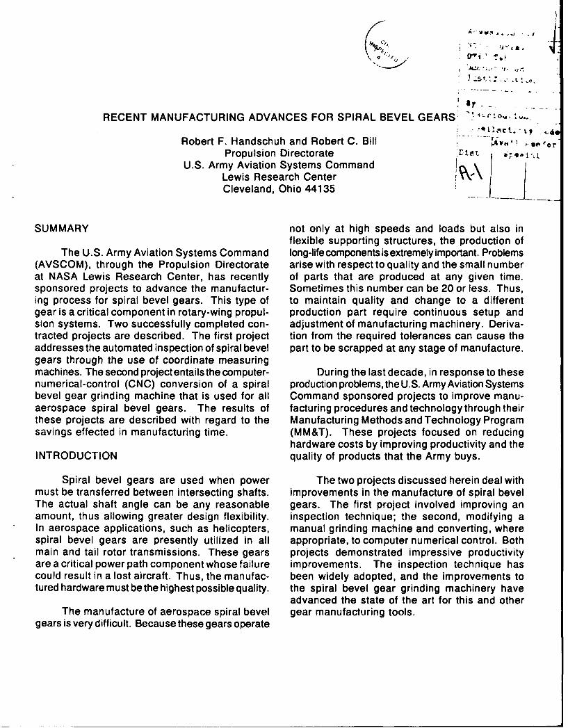
SUMMARY not only at high speeds and loads but also inflexible supporting structures, the production of
The U.S. Army Aviation Systems Command long-life components is extremely important. Problems(AVSCOM), through the Propulsion Directorate arise with respect to quality and the small numberat NASA Lewis Research Center, has recently of parts that are produced at any given time.sponsored projects to advance the manufactur- Sometimes this number can be 20 or less. Thus,ing process for spiral bevel gears. This type of to maintain quality and change to a differentgear is a critical component in rotary-wing propul- production part require continuous setup andsion systems. Two successfully completed con- adjustment of manufacturing machinery. Deriva-tracted projects are described. The first project tion from the required tolerances can cause theaddresses the automated inspection of spiral bevel part to be scrapped at any stage of manufacture.gears through the use of coordinate measuringmachines. The second project entailsthe computer- During the last decade, in response to thesenumerical-control (CNC) conversion of a spiral production problems, the U.S. Army Aviation Systemsbevel gear grinding machine that is used for all Command sponsored projects to improve manu-aerospace spiral bevel gears. The results of facturing procedures and technology through theirthese projects are described with regard to the Manufacturing Methods and Technology Programsavings effected in manufacturing time. (MM&T). These projects focused on reducing
hardware costs by improving productivity and theINTRODUCTION quality of products that the Army buys.
Spiral bevel gears are used when power The two projects discussed herein deal withmust be transferred between intersecting shafts. improvements in the manufacture of spiral bevelThe actual shaft angle can be any reasonable gears. The first project involved improving anamount, thus allowing greater design flexibility, inspection technique; the second, modifying aIn aerospace applications, such as helicopters, manual grinding machine and converting, wherespiral bevel gears are presently utilized in all appropriate, to computer numerical control. Bothmain and tail rotor transmissions. These gears projects demonstrated impressive productivityare a critical power path component whose failure improvements. The inspection technique hascould result in a lost aircraft. Thus, the manufac- been widely adopted, and the improvements totured hardware must be the highest possible quality, the spiral bevel gear grinding machinery have
advanced the state of the art for this and otherThe manufacture of aerospace spiral bevel gear manufacturing tools.
gears is very difficult. Because these gears operate
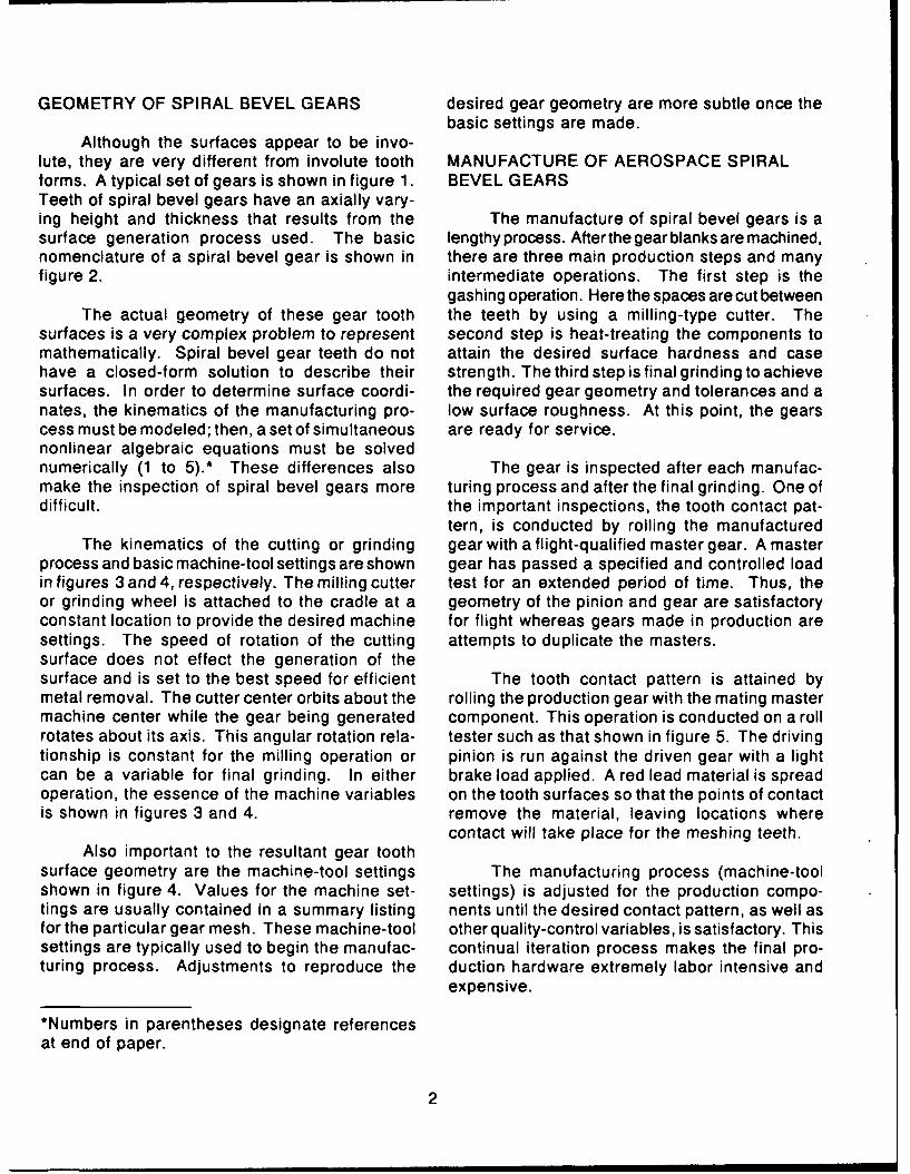
GEOMETRY OF SPIRAL BEVEL GEARS desired gear geometry are more subtle once thebasic settings are made.
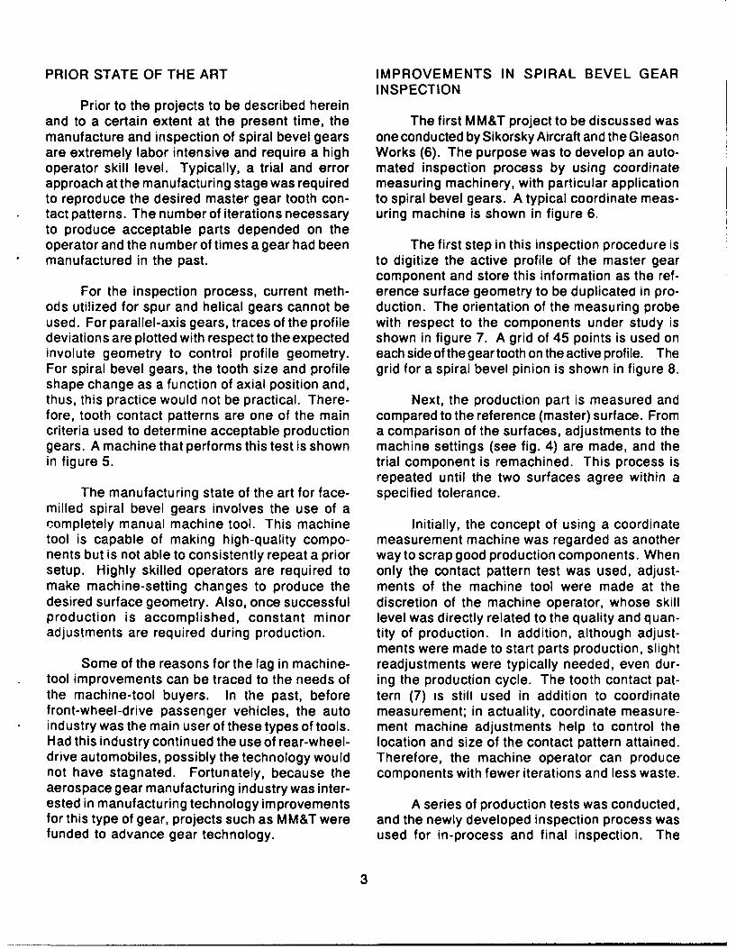
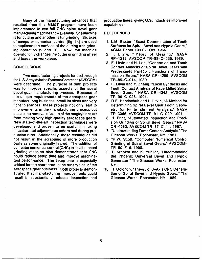
Although the surfaces appear to be invo-lute, they are very different from involute tooth MANUFACTURE OF AEROSPACE SPIRALforms. A typical set of gears is shown in figure 1. BEVEL GEARSTeeth of spiral bevel gears have an axially vary-ing height and thickness that results from the The manufacture of spiral bevel gears is asurface generation process used. The basic lengthy process. After the gear blanks are machined,nomenclature of a spiral bevel gear is shown in there are three main production steps and manyfigure 2. intermediate operations. The first step is the
gashing operation. Here the spaces are cut betweenThe actual geometry of these gear tooth the teeth by using a milling-type cutter. The
surfaces is a very complex problem to represent second step is heat-treating the components tomathematically. Spiral bevel gear teeth do not attain the desired surface hardness and casehave a closed-form solution to describe their strength. The third step is final grinding to achievesurfaces. In order to determine surface coordi- the required gear geometry and tolerances and anates, the kinematics of the manufacturing pro- low surface roughness. At this point, the gearscess must be modeled; then, a set of simultaneous are ready for service.nonlinear algebraic equations must be solvednumerically (1 to 5).* These differences also The gear is inspected after each manufac-make the inspection of spiral bevel gears more turing process and after the final grinding. One ofdifficult. the important inspections, the tooth contact pat-
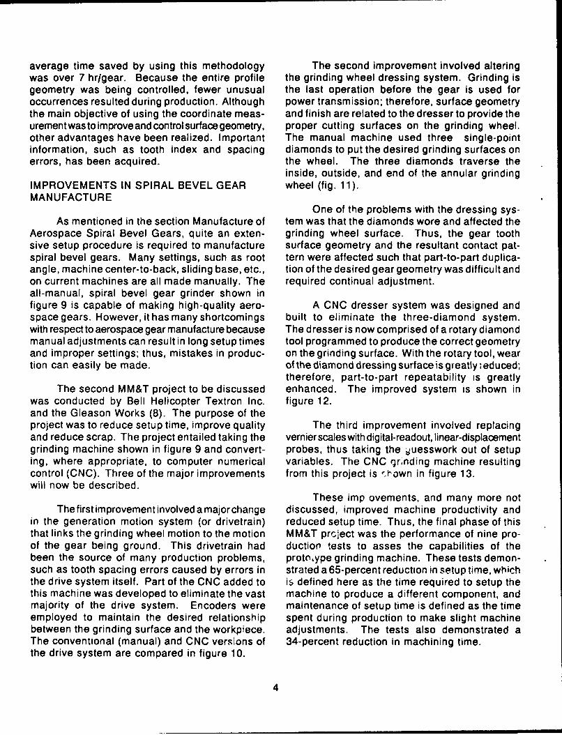
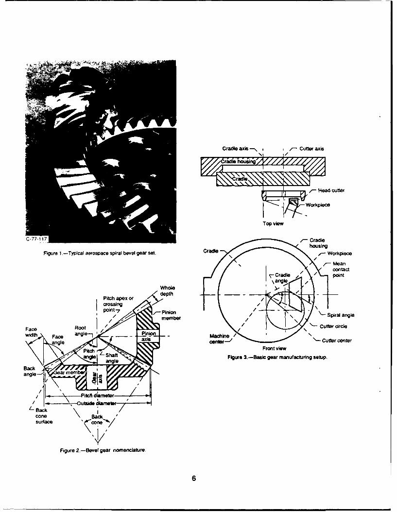
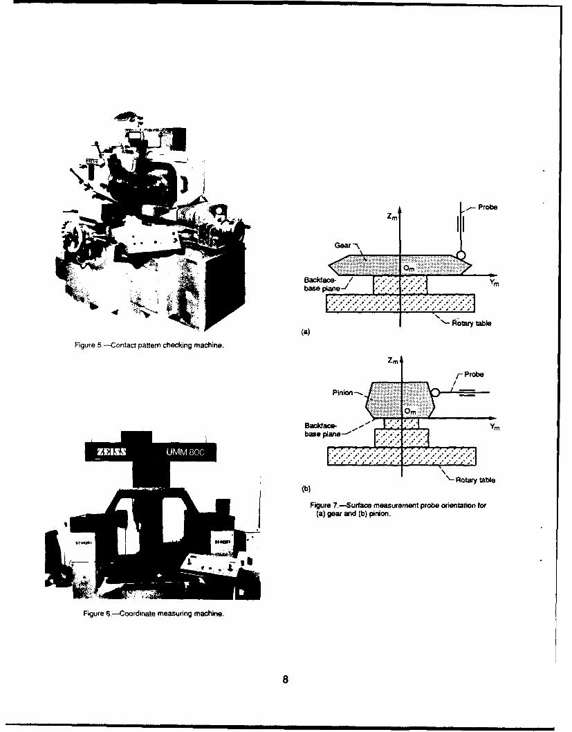
tern, is conducted by rolling the manufacturedThe kinematics of the cutting or grinding gear with a flight-qualified master gear. A master
process and basic machine-tool settings are shown gear has passed a specified and controlled loadin figures 3 and 4, respectively. The milling cutter test for an extended period of time. Thus, theor grinding wheel is attached to the cradle at a geometry of the pinion and gear are satisfactoryconstant location to provide the desired machine for flight whereas gears made in production aresettings. The speed of rotation of the cutting attempts to duplicate the masters.surface does not effect the generation of thesurface and is set to the best speed for efficient The tooth contact pattern is attained bymetal removal. The cutter center orbits about the rolling the production gear with the mating mastermachine center while the gear being generated component. This operation is conducted on a rollrotates about its axis. This angular rotation rela- tester such as that shown in figure 5. The drivingtionship is constant for the milling operation or pinion is run against the driven gear with a lightcan be a variable for final grinding. In either brake load applied. A red lead material is spreadoperation, the essence of the machine variables on the tooth surfaces so that the points of contactis shown in figures 3 and 4. remove the material, leaving locations where
contact will take place for the meshing teeth.Also important to the resultant gear tooth
surface geometry are the machine-tool settings The manufacturing process (machine-toolshown in figure 4. Values for the machine set- settings) is adjusted for the production compo-tings are usually contained in a summary listing nents until the desired contact pattern, as well asfor the particular gear mesh. These machine-tool other quality-control variables, is satisfactory. Thissettings are typically used to begin the manufac- continual iteration process makes the final pro-turing process. Adjustments to reproduce the duction hardware extremely labor intensive and
expensive.
*Numbers in parentheses designate referencesat end of paper.
2
PRIOR STATE OF THE ART IMPROVEMENTS IN SPIRAL BEVEL GEARINSPECTION
Prior to the projects to be described hereinand to a certain extent at the present time, the The first MM&T project to be discussed wasmanufacture and inspection of spiral bevel gears one conducted by Sikorsky Aircraft and the Gleasonare extremely labor intensive and require a high Works (6). The purpose was to develop an auto-operator skill level. Typically, a trial and error mated inspection process by using coordinateapproach at the manufacturing stage was required measuring machinery, with particular applicationto reproduce the desired master gear tooth con- to spiral bevel gears. A typical coordinate meas-tact patterns. The number of iterations necessary uring machine is shown in figure 6.to produce acceptable parts depended on theoperator and the number of times a gear had been The first step in this inspection procedure ismanufactured in the past. to digitize the active profile of the master gear
component and store this information as the ref-For the inspection process, current meth- erence surface geometry to be duplicatea in pro-
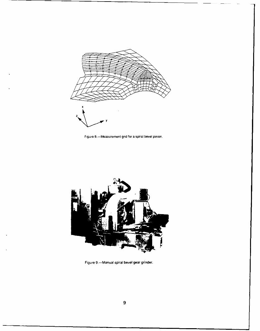
ods utilized for spur and helical gears cannot be duction. The orientation of the measuring probeused. For parallel-axis gears, traces of the profile with respect to the components under study isdeviations are plotted with respect to the expected shown in figure 7. A grid of 45 points is used oninvolute geometry to control profile geometry. each side of the gear tooth on the active profile. TheFor spiral bevel gears, the tooth size and profile grid for a spiral bevel pinion is shown in figure 8.shape change as a function of axial position and,thus, this practice would not be practical. There- Next, the production part is measured andfore, tooth contact patterns are one of the main compared to the reference (master) surface. Fromcriteria used to determine acceptable production a comparison of the surfaces, adjustments to thegears. A machine that performs this test is shown machine settings (see fig. 4) are made, and thein figure 5. trial component is remachined. This process is
repeated until the two surfaces agree within aThe manufacturing state of the art for face- specified tolerance.
milled spiral bevel gears involves the use of acompletely manual machine tool. This machine Initially, the concept of using a coordinatetool is capable of making high-quality compo- measurement machine was regarded as anothernents but is not able to consistently repeat a prior way to scrap good production components. Whensetup. Highly skilled operators are required to only the contact pattern test was used, adjust-make machine-setting changes to produce the ments of the machine tool were made at thedesired surface geometry. Also, once successful discretion of the machine operator, whose skillproduction is accomplished, constant minor level was directly related to the quality and quan-adjustments are required during production. tity of production. In addition, although adjust-
ments were made to start parts production, slightSome of the reasons for the lag in machine- readjustments were typically needed, even dur-
tool improvements can be traced to the needs of ing the production cycle. The tooth contact pat-the machine-tool buyers. In the past, before tern (7) is still used in addition to coordinatefront-wheel-drive passenger vehicles, the auto measurement; in actuality, coordinate measure-industry was the main user of these types of tools. ment machine adjustments help to control theHad this industry continued the use of rear-wheel- location and size of the contact pattern attained.drive automobiles, possibly the technology would Therefore, the machine operator can producenot have stagnated. Fortunately, because the components with fewer iterations and less waste.aerospace gear manufacturing industry was inter-ested in manufacturing technology improvements A series of production tests was conducted,for this type of gear, projects such as MM&T were and the newly developed inspection process wasfunded to advance gear technology, used for in-process and final inspection. The
3
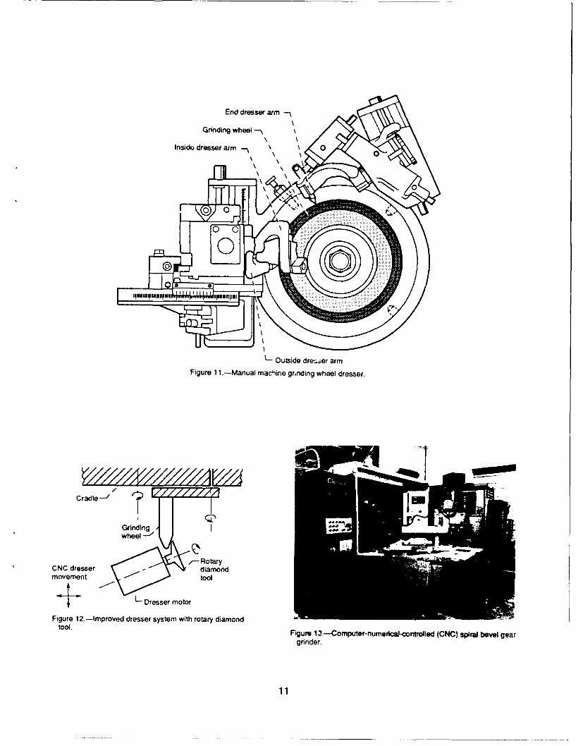
average time saved by using this methodology The second improvement involved alteringwas over 7 hr/gear. Because the entire profile the grinding wheel dressing system. Grinding isgeometry was being controlled, fewer unusual the last operation before the gear is used foroccurrences resulted during production. Although power transmission; therefore, surface geometrythe main objective of using the coordinate meas- and finish are related to the dresser to provide theurement was to improve and control surface geometry, proper cutting surfaces on the grinding wheel.other advantages have been realized. Important The manual machine used three single-pointinformation, such as tooth index and spacing diamonds to put the desired grinding surfaces onerrors, has been acquired. the wheel. The three diamonds traverse the
inside, outside, and end of the annular grindingIMPROVEMENTS IN SPIRAL BEVEL GEAR wheel (fig. 11).MANUFACTURE
One of the problems with the dressing sys-As mentioned in the section Manufacture of tern was that the diamonds wore and affected the
Aerospace Spiral Bevel Gears, quite an exten- grinding wheel surface. Thus, the gear toothsive setup procedure is required to manufacture surface geometry and the resultant contact pat-spiral bevel gears. Many settings, such as root tern were affected such that part-to-part duplica-angle, machine center-to-back, sliding base, etc., tion of the desired gear geometry was difficult andon current machines are all made manually. The required continual adjustment.all-manual, spiral bevel gear grinder shown infigure 9 is capable of making high-quality aero- A CNC dresser system was designed andspace gears. However, it has many shortcomings built to eliminate the three-diamond system.with respect to aerospace gear manufacture because The dresser is now comprised of a rotary diamondmanual adjustments can result in long setup times tool programmed to produce the correct geometryand improper settings; thus, mistakes in produc- on the grinding surface. With the rotary tool, weartion can easily be made. of the diamond dressing surface is greatly ;educed;
therefore, part-to-part repeatability is greatlyThe second MM&T project to be discussed enhanced. The improved system is shown in
was conducted by Bell Helicopter Textron Inc. figure 12.and the Gleason Works (8). The purpose of theproject was to reduce setup time, improve quality The third improvement involved replacingand reduce scrap. The project entailed taking the vernierscales with digital-readout, linear-displacementgrinding machine shown in figure 9 and convert- probes, thus taking the ýuesswork out of setuping, where appropriate, to computer numerical variables. The CNC grinding machine resultingcontrol (CNC). Three of the major improvements from this project is e.hown in figure 13.will now be described.
These imp ovements, and many more notThefirst improvement involved amajorchange discussed, improved machine productivity and
in the generation motion system (or drivetrain) reduced setup time. Thus, the final phase of thisthat links the grinding wheel motion to the motion MM&T project was the performance of nine pro-of the gear being ground. This drivetrain had duction tests to asses the capabilities of thebeen the source of many production problems, proto ,ype grinding machine. These tests demon-such as tooth spacing errors caused by errors in strated a 65-percent reduction in setup time, whichthe drive system itself. Part of the CNC added to is defined here as the time required to setup thethis machine was developed to eliminate the vast machine to produce a different component, andmajority of the drive system. Encoders were maintenance of setup time is defined as the timeemployed to maintain the desired relationship spent during production to make slight machinebetween the grinding surface and the workpiece. adjustments. The tests also demonstrated aThe conventional (manual) and CNC versions of 34-percent reduction in machining time.the drive system are compared in figure 10.
4
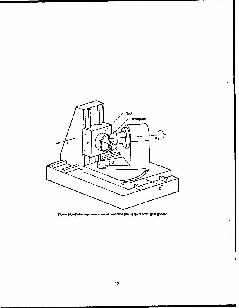
Many of the manufacturing advances that production times, giving U.S. industries improvedresulted from this MM&T program have been capabilities.implemented in two full CNC spiral bevel gearmanufacturing machines now available. One machine REFERENCESis for cutting and another is for grinding. Six axesof computer numerical control (fig. 14) are used 1. L.M. Baxter, "Exact Determination of Toothto duplicate the motions of the cutting and grind- Surfaces for Spiral Bevel and Hypoid Gears,"ing operation (9 and 10). Now, the machine AGMA Paper 139.02, Oct. 1966.operator only changes the cutter or grinding wheel 2. F. Litvin, "Theory of Gearing,* NASAand loads the workpiece. RP-1212, AVSCOM TR-88-C-035, 1989.
3. F. Litvin and H. Lee, "Generation and ToothCONCLUSIONS Contact Analysis of Spiral Bevel Gears with
Predesigned Parabolic Functions of Trans-Two manufacturing projects funded through mission Errors," NASA CR-4259, AVSCOM
the U.S. ArmyAviation SystemsCommand (AVSCOM) TR-89-C-01 4, 1989.were described. The purpose of both projects 4. F. Litvin and Y. Zhang, "Local Synthesis andwas to improve specific aspects of the spiral Tooth Contact Analysis of Face-Milled Spiralbevel gear manufacturing process. Because of Bevel Gears,3 NASA CR-4342, AVSCOMthe unique requirements of the aerospace gear TR-90-C-028, 1991.manufacturing business, small lot sizes and very 5. R.F. Handschuh and L. Litvin, "A Method fortight tolerances, these projects not only lead to Determining Spiral Bevel Gear Tooth Geom-improvements in the manufacturing process but etry for Finite Element Analysis," NASAalso to the removal of some of the magic/black art TP-3096, AVSCOM TR-91-C-020, 1991.from making very high-quality aerospace gears. 6. H. Frint, "Automated Inspection and Preci-New state-of-the-art inspection techniques were sion Grinding of Spiral Bevel Gears," NASAdeveloped and proven to be useful in making CR-4083, AVSCOM TR-87-C-1 1, 1987.machine-tool adjustments before and during pro- 7. "Understanding Tooth Contact Analysis,"Theduction runs. Additionally, these techniques did Gleason Works, Rochester, NY, 1981.not result in the scrapping of more production 8. "H.W. Scott, "Computer Numerical Controlparts as some originally feared. The addition of Grinding of Spiral Bevel Gears," AVSCOM-computer numerical control (CNC) to an all-manual TR-90-F-6, 1990.grinding machine also demonstrated that CNC 9. T. Krenzer and K. Yunker, "Understandingcould reduce setup time and improve machine- the Phoenix Universal Bevel and Hypoidtool performance. The setup time is especially Generator," The Gleason Works, Rochester,critical for the short production runs typical of the NY.aerospace gear business. Both projects demon- 10. R. Goldrich, "Theory of 6-Axis CNC Genera-strated that manufacturing improvements could tion of Spiral Bevel and Hypoid Gears," Theresult in substantially reduced inspection and Gleason Works, Rochester, NY, 1989.
5
Cradle axis -. Cutter axis
Top view
Figure I.-Typical aerospace spiral bevel gear set.Crf oklc
contact
vCradle / / point
Whole
Pitch apex ordetcrossing
membe -/-Spiral angle
P~ch Front view
900 haftFigure 3.-Basic gear manufacturing setup.
angle a membe
LBack
surface *wcone~m/
Figure 2.-Bevel gear nomenclature.
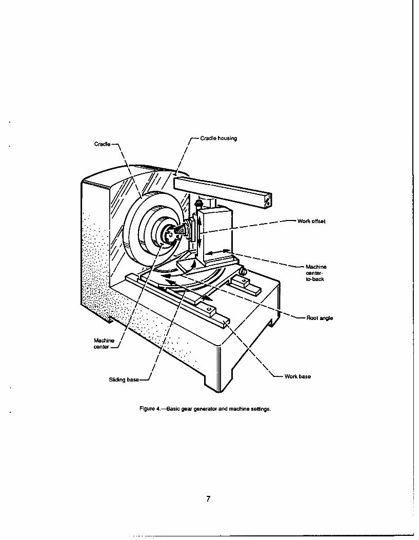
Crde~ Cradle housing
Work offset
-Machine
center-to-back
-Root angle
Sliding base-i Work base
Figure 4.-Basic gear generator and machine settings.
-Probe
Zm I
Bckface- / .S.SS
base lane-/
(a) '- otary table
Figure 5.-Contact pattern checking machine.
ZM1
r Probe
Pinion----
Backface- YM
'-Rotary table(b)
Figure 7.-Surface measurement probe orientation for(a) gear and (b) pinion.
Figure 6.-Coordinate measuring machine.
x
z
A-,ý y
Figure 8.-Measurement grid for a spiral bevel pinion.
dJ JFigure 9.-Manual spiral bevel gear grinder.
9
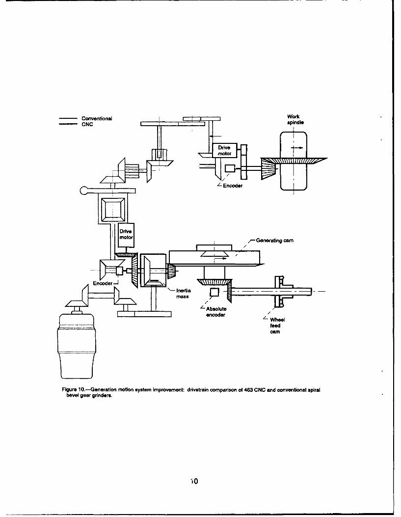
Conventional •: Wock
SCNC • ndle
/-- E•r
F Generating cam, /
S• Inertiamass •]
/-- AbsoluteF_ " .................. feed
Figure 10.•Generatlon motion system improvement: drivetraln oomparison of 463 CNC sad conventional spiralbevel gear grinders.
tO
End dresser arm -
Grinding wheel -
Inside dresser arm 0' 0
'i utie rq e r
Grndn IZ
COusid dressere ariaon
Figurei12.-Improved dresser systemrwithnrotaryldiamondr.
Grgrdnder.
wheel
/-Tool
Figure 14.-Fufl-computer-numordcal-controled (CNC) spiral bevel gear grinider.
12
I IASA Report Documentation Page
1. Report No' NASA TM- 104479 2. Government Acoession No. 3. Recipient's Catalog No.
AVSCOM TR 91 - C-022
4. Title and Subtitle 5. Report Date
Recent Manufacturing Advances for Spiral Bevel Gears
6. Performing Organization Code
7. Author(s) 8. Performing Organization Report No.
Robert F. Handschuh and Robert C. Bill E-6326
10. Work Unit No.9. Performing Organization Name and Address 505 -63-36
NASA Lewis Research Center 1L162211A47ACleveland, Ohio 44135 - 3191 11. Contract or Grant No.andPropulsion DirectorateU.S. Army Aviation Systems CommandCleveland, Ohio 44135- 3191 13. Type of Report and Period Covered
12. Sponsoring Agency Name and Address Technical MemorandumNational Aeronautics and Space AdministrationWashington, D.C. 20546-0001 14. Sponsoring Agency Code
andU.S. Army Aviation Systems CommandSt. Louis, Mo. 63120- 1798
15. Supplementary Notes
Prepared for the Aerotech '91 sponsored by the Society of Automotive Engineers, Long Beach, California,September 23-26, 1991. Responsible person, Robert F. Handschuh, (216) 433-3969.
16. Abstract
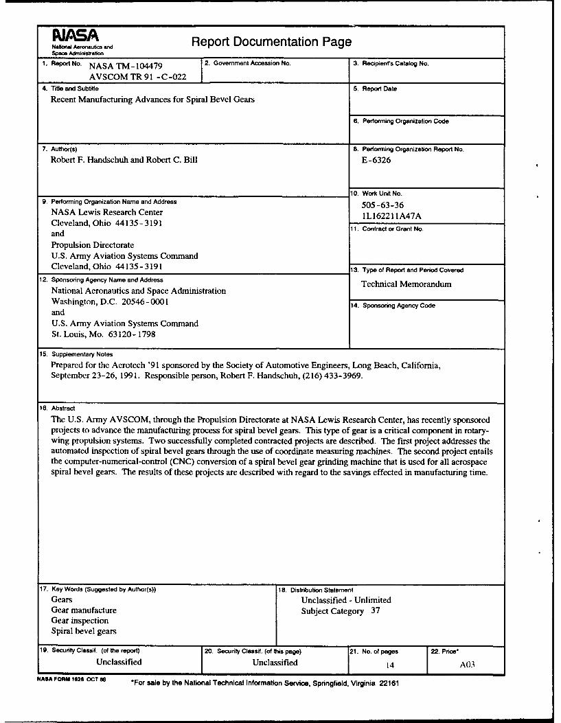
The U.S. Army AVSCOM, through the Propulsion Directorate at NASA Lewis Research Center, has recently sponsoredprojects to advance the manufacturing process for spiral bevel gears. This type of gear is a critical component in rotary-wing propulsion systems. Two successfully completed contracted projects are described. The first project addresses theautomated inspection of spiral bevel gears through the use of coordinate measuring machines. The second project entailsthe computer-numerical-control (CNC) conversion of a spiral bevel gear grinding machine that is used for all aerospacespiral bevel gears. The results of these projects are described with regard to the savings effected in manufacturing time.
17. Key Words (Suggested by Author(s)) 18. Distribution Statement
Gears Unclassified - UnlimitedGear manufacture Subject Category 37Gear inspectionSpiral bevel gears
19. Security Classif. (of the report) 20. Security Classif. (of this page) 21. No. of pages 22. Price*
Unclassified Unclassified 14 A03
NASA FORM 1626 OCT 86 *For sale by the National Technical Information Service, Springfield, Virginia 22161