Recent Developments in PAM-CRASH/SAFE V2006 · PDF filePAM-CRASH/SAFE 2G evolution •2006...
77
Copyright © ESI Group, 2006. All rights reserved. Recent Developments in PAM-CRASH/SAFE V2006 C. Thibaud C. Thibaud Bad Soden, 2006 Bad Soden, 2006 Engineering System International GmbH Engineering System International GmbH
-
Upload
trinhhuong -
Category
Documents
-
view
244 -
download
4
Transcript of Recent Developments in PAM-CRASH/SAFE V2006 · PDF filePAM-CRASH/SAFE 2G evolution •2006...

Copyright © ESI Group, 2006. All rights reserved.
Recent Developments in PAM-CRASH/SAFE V2006
C. ThibaudC. Thibaud
Bad Soden, 2006Bad Soden, 2006Engineering System International GmbHEngineering System International GmbH

Copyright © ESI Group, 2006. All rights reserved.
Outlines
• Introduction
• Version 2006• New features
and performance enhancement
• Multi-Model-Coupling
• Implicit
• Conclusion

Copyright © ESI Group, 2006. All rights reserved.
PAM-CRASH/SAFE 2G
• 2002 – 2005• Reengineering + Performance
• Focused • On large distributed memory low-cost clusters• Stable computation • Optimized memory consumption• QA is performed on one code
• New Features

Copyright © ESI Group, 2006. All rights reserved.
PAM-CRASH/SAFE 2G evolution
• 2006
One scalable code to enable crash and safety simulation (including FPM, Multi-Model-Coupling and implicit)• New Features and Multi-Model-Coupling
• Focused on modelisation of damage and failure
• User friendliness and Quality
• Implicit• First release 2006
Copyright © ESI Group, 2006. All rights reserved.
Version 2006
New features
-
Multi-Model-Coupling

Copyright © ESI Group, 2006. All rights reserved.
Constraint
• MTOCO (Multiple To One node COnstraint) • Generalized Rigid body
• One independent node with user specified coordinates• Set of dependent nodes• Specified DOFs for dependent nodes are constrained to
independent nodes
• Known as Nastran-RBE2• Characteristics
• Boundary condition could be applied to the independent node only.
• Restriction: independent node couldn’t not be a dependent node of another MTOCO
• MTOCO could degenerate to RBODY type 0• Independent node specified on COG location• All 6 DOFs are selected to be constrained
Copyright © ESI Group, 2006. All rights reserved.
Constraint
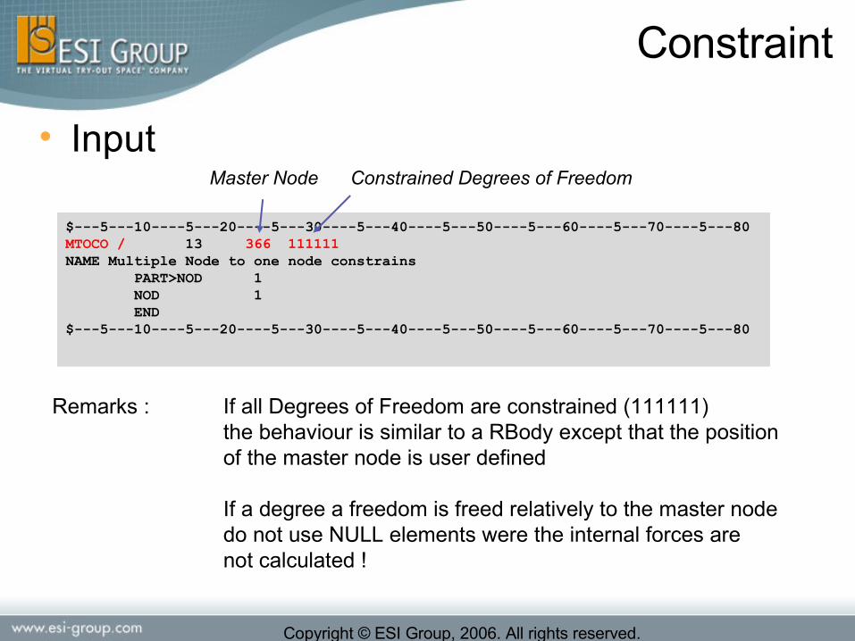
• Input
$---5---10----5---20----5---30----5---40----5---50----5---60----5---70----5---80MTOCO / 13 366 111111NAME Multiple Node to one node constrains PART>NOD 1 NOD 1 END$---5---10----5---20----5---30----5---40----5---50----5---60----5---70----5---80
Constrained Degrees of Freedom
Remarks : If all Degrees of Freedom are constrained (111111) the behaviour is similar to a RBody except that the positionof the master node is user defined
If a degree a freedom is freed relatively to the master nodedo not use NULL elements were the internal forces arenot calculated !
Master Node
Copyright © ESI Group, 2006. All rights reserved.
Constraint
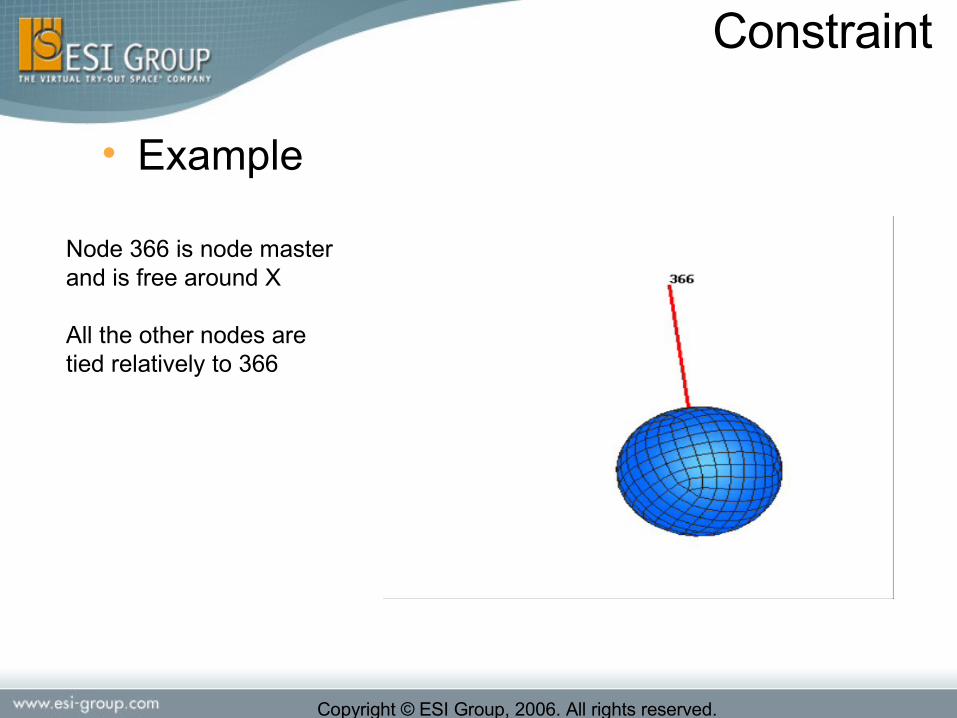
• Example
Node 366 is node masterand is free around X
All the other nodes aretied relatively to 366

Copyright © ESI Group, 2006. All rights reserved.
Rigid Bodies
• The inertia for RBody Type 3 can be defined with the complete matrix
$---5---10----5---20----5---30----5---40----5---50----5---60----5---70----5---80RBODY / 2101 3 900002 900012 900022 0NAME Rigid Body Type 3 1 4.29 110000. 120000. 110000. -55.-90000. -30. PART>NOD 2101 3102 NOD 850101 850102 850103 END$---5---10----5---20----5---30----5---40----5---50----5---60----5---70----5---80
I11, I22, I33, I12, I13, I23
Prescribed full inertia tensor

Copyright © ESI Group, 2006. All rights reserved.
Contact Interfaces
• Code Tuning - CRASH/SAFE contacts• MPI communication completely redesigned
• To avoid scalability problems with large number of interfaces• Dummies• Human models• Interior models• ...
• Done for:• Type 33, 34, 36, 37, 46
• Partly done for:• Type 54 (Attention, intensive use of type 54 may still cause
scalability problems)
• Not done for:• Type 44
• Full integration into new MPI paradigm for type 44 and 54 planned in v2007
Copyright © ESI Group, 2006. All rights reserved.
Contact Interfaces
• Code Tuning - CRASH/SAFE contacts• Main objectives for the new implementation:
• Load balance between element and contact computation• Less communication• Better synchronization of different communication tasks• Simplification of the contact routines
• Positive side effects:• Optimize memory consumption• Performance and memory improved for contact thickness
based on PART• User friendliness (two contact tuning parameters are
obsolete)• NACC – no user input needed. Automatic (-1) and save internal
computation• THKEXT – no user input needed. Automatic computation

Copyright © ESI Group, 2006. All rights reserved.
• Example / Performances
30 % less memory consumption
Contact Interfaces
Copyright © ESI Group, 2006. All rights reserved.
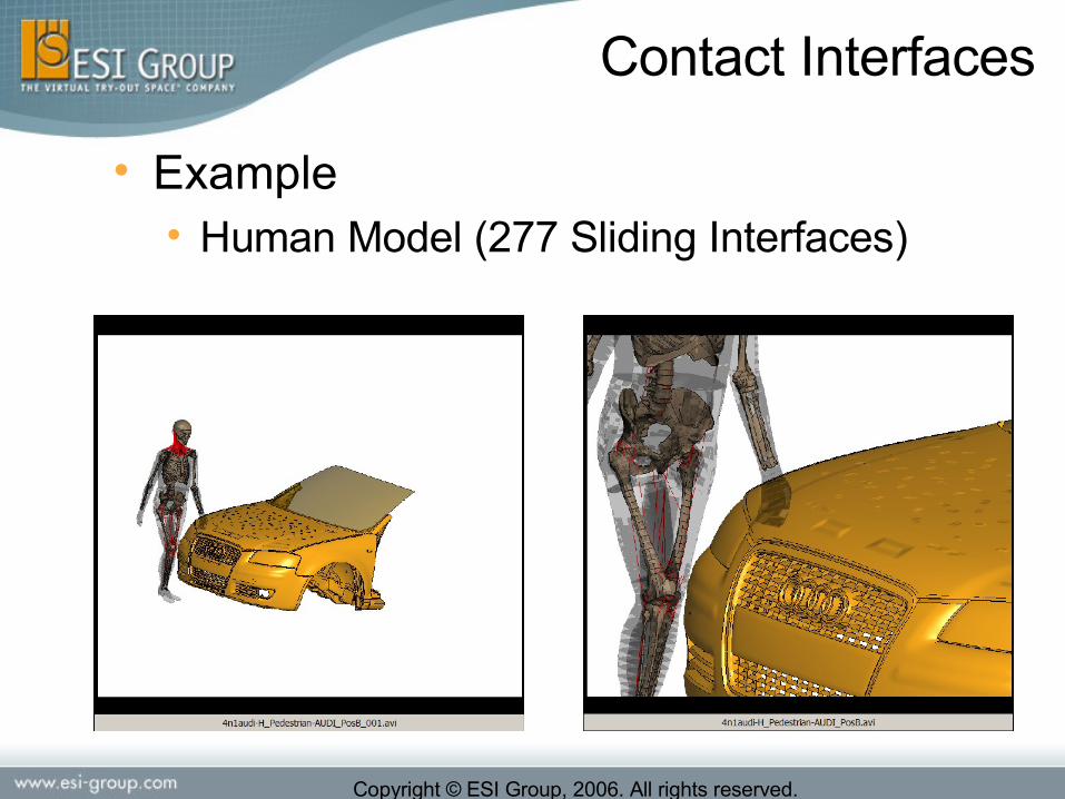
• Example• Human Model (277 Sliding Interfaces)
Contact Interfaces

Copyright © ESI Group, 2006. All rights reserved.
0.00
5.00
10.00
15.00
20.00
25.00
30.00
2 4 8 16
CPU
Ho
urs V2005.1
V2006
• Performances• Human Model (277 Sliding interfaces)
Contact Interfaces

Copyright © ESI Group, 2006. All rights reserved.
• Eroding Contact• Necessary to take care of the solid-element
elimination in the contact to avoid to under estimate the material resistance after failure.
• For die-cast structures under compression loads• For honeycombs structures• For SPH impact on solid structures
Contact Interfaces

Copyright © ESI Group, 2006. All rights reserved.
• Implemented for Contact 33, 34 and 36• Activated on CARD 6 (I5)
$---5---10----5---20----5---30----5---40----5---50----5---60----5---70----5---80CNTAC / 1 34NAME ball-block 0.0 0.0 1.0 0 0 0.1 0.0 0 0.0 0.1 0 0.0$---5---10----5---20----5---30----5---40----5---50----5---60----5---70----5---80$ IEROD 0 1 0 0
PART 778 END PART 777 END$---5---10----5---20----5---30----5---40----5---50----5---60----5---70----5---80
Erosion activated
Contact Interfaces

Copyright © ESI Group, 2006. All rights reserved.
• Example
Contacts 34
Master :Aluminium foam with damage
Slave :Impacting ball (shells)
Contact Interfaces
Copyright © ESI Group, 2006. All rights reserved.
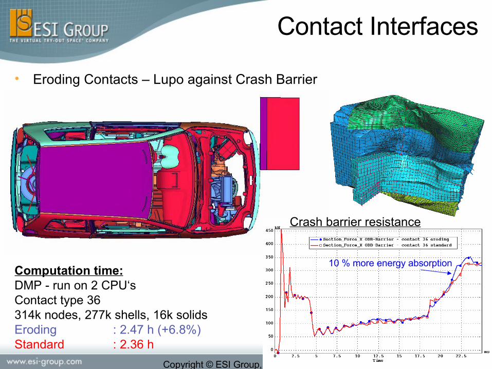
• Eroding Contacts – Lupo against Crash Barrier
Computation time:DMP - run on 2 CPU‘sContact type 36314k nodes, 277k shells, 16k solidsEroding : 2.47 h (+6.8%)Standard : 2.36 h
Crash barrier resistance
10 % more energy absorption
Contact Interfaces
Copyright © ESI Group, 2006. All rights reserved.
Materials
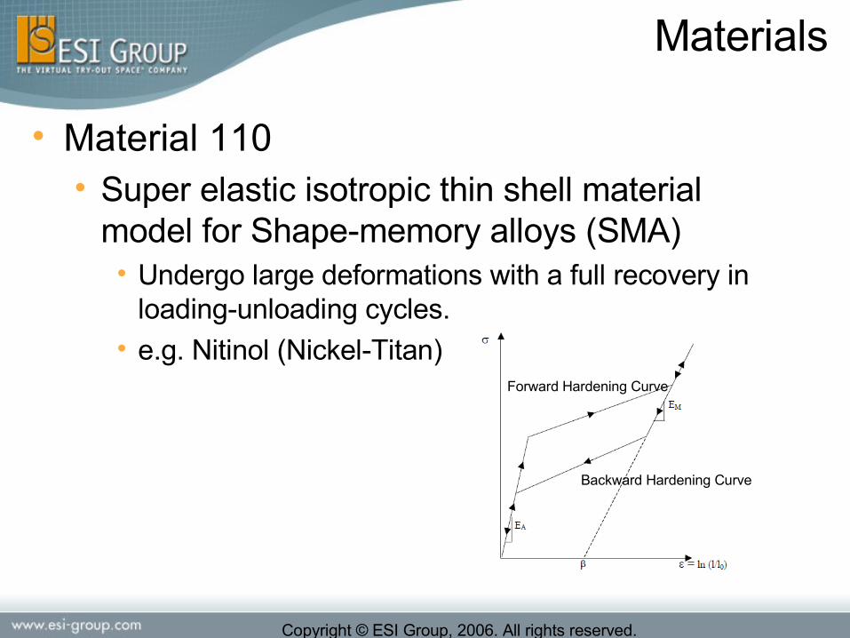
• Material 110• Super elastic isotropic thin shell material
model for Shape-memory alloys (SMA)• Undergo large deformations with a full recovery in
loading-unloading cycles.• e.g. Nitinol (Nickel-Titan)
Forward Hardening Curve
Backward Hardening Curve
Copyright © ESI Group, 2006. All rights reserved.
Materials
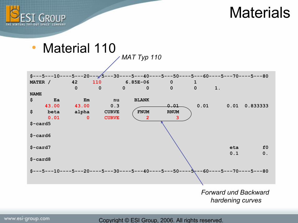
• Material 110
$---5---10----5---20----5---30----5---40----5---50----5---60----5---70----5---80MATER / 42 110 6.85E-06 0 1 0 0 0 0 0 0 1.NAME $ Ea Em nu BLANK 43.00 43.00 0.3 0.01 0.01 0.01 0.833333$ beta alpha CURVE FNUM RNUM 0.01 0 CURVE 2 3$-card5 $-card6 $-card7 eta f0 0.1 0.$-card8
$---5---10----5---20----5---30----5---40----5---50----5---60----5---70----5---80
Forward und Backward hardening curves
MAT Typ 110
Copyright © ESI Group, 2006. All rights reserved.
Materials
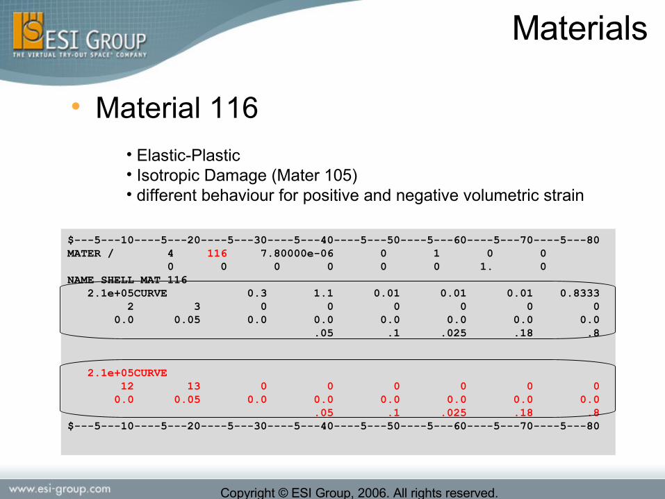
• Material 116
• Elastic-Plastic• Isotropic Damage (Mater 105)• different behaviour for positive and negative volumetric strain
$---5---10----5---20----5---30----5---40----5---50----5---60----5---70----5---80MATER / 4 116 7.80000e-06 0 1 0 0 0 0 0 0 0 0 1. 0NAME SHELL MAT 116 2.1e+05CURVE 0.3 1.1 0.01 0.01 0.01 0.8333 2 3 0 0 0 0 0 0 0.0 0.05 0.0 0.0 0.0 0.0 0.0 0.0 .05 .1 .025 .18 .8
2.1e+05CURVE 12 13 0 0 0 0 0 0 0.0 0.05 0.0 0.0 0.0 0.0 0.0 0.0 .05 .1 .025 .18 .8 $---5---10----5---20----5---30----5---40----5---50----5---60----5---70----5---80
Copyright © ESI Group, 2006. All rights reserved.
Materials
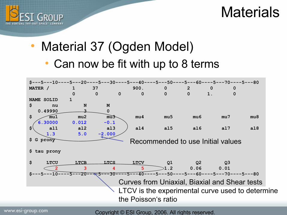
• Material 37 (Ogden Model) • Can now be fit with up to 8 terms
$---5---10----5---20----5---30----5---40----5---50----5---60----5---70----5---80MATER / 1 37 900. 0 2 0 0 0 0 0 0 0 0 1. 0NAME SOLID 1$ nu N M 0.49990 3 0$ mu1 mu2 mu3 mu4 mu5 mu6 mu7 mu8 6.30000 0.012 -0.1 $ al1 al2 al3 al4 al5 al6 al7 al8 1.3 5.0 -2.000$ G prony
$ tau prony
$ LTCU LTCB LTCS LTCV Q1 Q2 Q3 2 3 4 5 1.2 0.06 0.01$---5---10----5---20----5---30----5---40----5---50----5---60----5---70----5---80
Curves from Uniaxial, Biaxial and Shear testsLTCV is the experimental curve used to determinethe Poisson‘s ratio
Recommended to use Initial values
Copyright © ESI Group, 2006. All rights reserved.
Materials
• Material 223 improvements:• Optional input per unit length• Optional pre-stresses for each Degree of freedom
• Material 143/36 – Optimisation of the stability • In case of Strain rate dependency • In case of Stiffness hardening
• Kinematics Hardening for Solids (beta)• Elastic-plastic Type 1

Copyright © ESI Group, 2006. All rights reserved.
Materials
• Material 42• orthotropic material with switching to an isotropic material when a
criterion is reached i.e. volumetric compaction or total strain along one direction
• Young or shear modulus and a yielding curve are defined for each direction
• Compression and tension behavior are distinguished
• Coupling of the yielding curve with other direction by a scale factor depending of the behavior of other direction
T
L
W
Tensile loadingTensile loading
Tensile unloadingTensile unloadingCompression loadingCompression loading
Compression unloadingCompression unloading
EEtensiontension
EEcompressioncompression

Copyright © ESI Group, 2006. All rights reserved.
Materials
• Material 42• Failure limit and switching limit depending of all component
of total strain tensor and volumetric strain can be defined with a power law
• Strain rate effects can be considered through a Cowper- Symonds law or via curves (with a strain rate curve multiplier)
1== βα
200== βα
2== βα
tuε
nuε
,
( , , , , , , , , , , )
min( ,0.)
max( ,0.)
iF
ii
i F
i T T L L W W TL LW TW VOL VOL
Fα
εε
ε ε ε ε ε ε ε γ γ γ ε εε εε ε
− + − + − + − +
−
+
=
=
=
=
∑

Copyright © ESI Group, 2006. All rights reserved.
Materials
• Material 42• When the switching limit is reached the
material becomes isotropic
• Elastic-plastic• A damage depending of the plastic strain can be
defined

Copyright © ESI Group, 2006. All rights reserved.
Materials
• Example for barrier material

Copyright © ESI Group, 2006. All rights reserved.
Materials
• Example for glued models

Copyright © ESI Group, 2006. All rights reserved.
Materials
• Material 304 (Only for TIED Elements)• As for material 303 uses a formulation stress/deformation
• a distance hcont imposed in material cards is used to solve deformation.
• The displacement of ideal position is already modify by these hcont.
• Zero distance between master and slave are not allowed
master
conth
x∆=ε
dx
∫∫∫ ===
=
UNUNTNTNNN
UN
TN
N
U
T
UN
TN
N
ddd
d
d
d
G
G
E
d
d
d
'
0
; ;
00
00
00
γγγγεε
γγε
ττσ

Copyright © ESI Group, 2006. All rights reserved.
Materials
• Material 304• Different Modules can be defined in tension and
compression
Shear unloadingShear loadingShear Curve (ICUT_NT, ICUT_NU)
Compression unloadingTension loadingTension Curve (ICUT_NN)
Tension unloadingCompression loadingCompression Curve (ICUC_NN)
Abscissa negativeAbscissa positive
Tensile loadingTensile loading
Tensile unloadingTensile unloadingCompression loadingCompression loading
Compression unloadingCompression unloading
EEtensiontension
EEcompressioncompression
σσYield curve for tensionYield curve for tension
Positive strainPositive strain
+ε+ε−ε−ε
Negative strainNegative strain
σσYield curve for compressionYield curve for compression
+ε+ε−ε−εPositive strainPositive strainNegative strainNegative strain

Copyright © ESI Group, 2006. All rights reserved.
Materials
• Material 304• No coupling of DoF in rotation, to avoid negative effects through
bending observed in the Peeling case.
• The terms depending of ecentration can be deactivated, in the force projection by setting IDEABEN=1.
• These terms introduce out-of-plane forces in the master surface that may excite the third Hourglass modes.
I6DOF
I3DOF

Copyright © ESI Group, 2006. All rights reserved.
Materials
• Material 304• For each direction, a damage per direction could be define via a
lookup table depending of the deformation in normal and 2 shear direction in orthotropic plan
• The connection are eliminated when these damage reach 1
Copyright © ESI Group, 2006. All rights reserved.
Materials
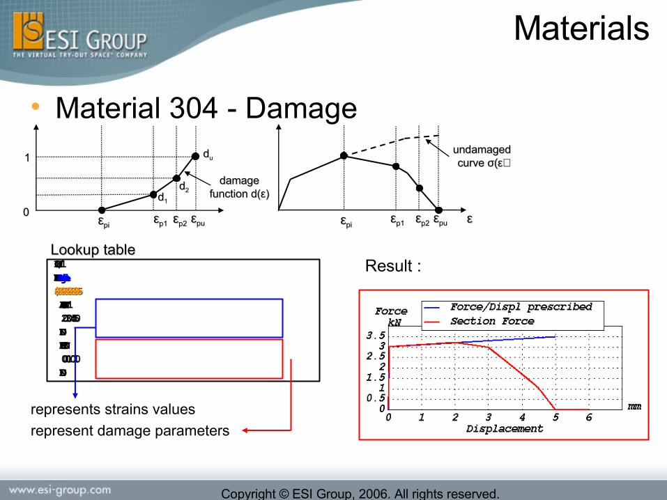
• Material 304 - Damage
εεpipi εεp2p2 εεpupu
11undamaged undamaged curve curve σ(ε)σ(ε)
dd11
εεpipi εεp2p2 εεpupu
dduu
damage damage function d(function d(εε))
εεεεp1p1
dd22
00 εεp1p1
LOOKU / 1LOOKU / 1NAME NAME Damage tableDamage table $---5---10----5---20----5---30----5$---5---10----5---20----5---30----5 ARGUMENT 1ARGUMENT 1 2.0 3.0 4.5 5.02.0 3.0 4.5 5.0 ENDEND FUNCTIONFUNCTION 0.0 0.1 0.7 1.00.0 0.1 0.7 1.0 END END
Lookup tableLookup table
represents strains values
represent damage parameters
Result :

Copyright © ESI Group, 2006. All rights reserved.
Materials
• Material 304 - Input$---5---10----5---20----5---30----5---40----5---50----5---60----5---70----5---80MATER / 3 304
NAME TIED Material type 304$ SDMP1 hcont D p Nfilt IDEABEN 0.1 0.1 10 0$ Ortho. Props in Compression N-Direction$ EC_NN CURVE ICUC_NN CELC_NN ELIC_NN 5 $ Ortho. Props in Tension N-Direction$ ET_NN CURVE ICUT_NN CELT_NN ELIT_NN 5 2. $ Ortho. Props in Shear NT-Direction $ G_NT CURVE ICUT_NT CEL_NN ELIT_NT 5 2. $ Ortho. Props in Shear NU-Direction $ G_NU CURVE ICUT_NU CEL_NU ELIT_NU 5 $---5---10----5---20----5---30----5---40----5---50----5---60----5---70----5---80

Copyright © ESI Group, 2006. All rights reserved.
Materials
• Material 304 - Input$ Damage in Tensile in N-Direction$ LKT_N INT_N INT_NT INT_NU 1 1 $ Damage in Compression in N-Direction$ LKC_N INC_N INT_NT INT_NU 1 1 $ Damage in Shear in NT-Plan
$ Damage in Shear in NU-Direction
$---5---10----5---20----5---30----5---40----5---50----5---60----5---70----5---80LOOKU / 1NAME LOOKUP TABLE FOR DAMAGE MAT 3 (TYPE 304) ARGUMENT 1 2.0 3.0 4.5 5.0 END FUNCTION 0.0 0.1 0.7 1.0 END$---5---10----5---20----5---30----5---40----5---50----5---60----5---70----5---80
Copyright © ESI Group, 2006. All rights reserved.
Materials
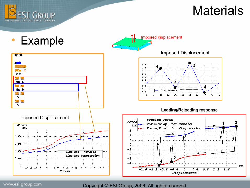
• ExampleMATER / 3 304MATER / 3 304
NAME NAME TIED mater-304TIED mater-304$---5---10----5---20----5---30----5---40-$---5---10----5---20----5---30----5---40-$ SDMP1 hcont D $ SDMP1 hcont D 0.1 1.00.1 1.0$ EC_NN ICUC_NN $ EC_NN ICUC_NN 0.6CURVE 31 0.6CURVE 31 $ ET_NN ICUT_NN $ ET_NN ICUT_NN 0.75CURVE 300.75CURVE 30$ G_NT ICUT_NT $ G_NT ICUT_NT 55$ G_NU ICUT_NU $ G_NU ICUT_NU 55
Loading/Reloading responseLoading/Reloading response
Imposed Displacement
Imposed displacement
11
22
33
44
22
33
44
Imposed Displacement11

Copyright © ESI Group, 2006. All rights reserved.
Link Materials
• PLINKS – V97/2002• Meshing independent spot-welds
• Contact 42 / Plinks
• MULTI-PLINKS – V2001• Multi-Plink to transmit torsion• Better representation of the spot-weld stiffness without localisation
• MPC-PLINKS – V2005• To manage spot-weld failure with accuracy
• Tension/Compression effects• Bending effects
Multi-point kinematic constraint
Spring-beam element
Multi-point kinematic constraint

Copyright © ESI Group, 2006. All rights reserved.
Link Materials
• FAT spotweld test data

Copyright © ESI Group, 2006. All rights reserved.
Link Materials
• Material 224• Simplified MPC-Plink with
penalty formulation• Simplified input• Advantage of the MPC-PLINKs
Multi Point Constraint
Multi Point Constraint
$---5---10----5---20----5---30----5---40----5---50----5---60----5---70----5---80MATER / 3 224 1.00000e-05 0 0 0 0 0 0 0 0 0 0 1. 0NAME Penalty spring beam$ SLFACMT SLFACMR SDMP1 Mass Inertia I3DOF IDRUPT 0.10 0.10 0.1 1.E-3 1.E-3 0 0
$---5---10----5---20----5---30----5---40----5---50----5---60----5---70----5---80
1D element (Spring beam)
The material definition can be empty (8 blank cards) -> self calibrating

Copyright © ESI Group, 2006. All rights reserved.
Link Materials
• Monitoring of spot-weld rupture without failure • only for PLINK/ELINK (MATER 302)
$---5---10----5---20----5---30----5---40----5---50----5---60----5---70----5---80MATER / 2 302 7.8E-06 0 0 0 0 0 0 0 0 1. NAME MAT_2_Plink $ SLFACM FSNVL DELTNL IFLGC 0.1 0. 0$ I3DOF TOLCOR IDRUP 0 1
RUPMO / 1 0 1 NAME Rupture Model 1$ FAILT FAILD AFN AFS A1 A2 INTF 0.0 0.0 25. 70. 2. 2. 10END$---5---10----5---20----5---30----5---40----5---50----5---60----5---70----5---80
Copyright © ESI Group, 2006. All rights reserved.
Link Materials
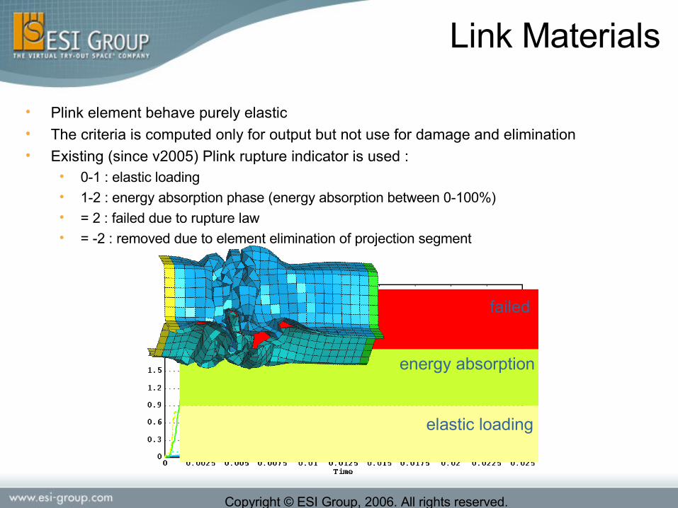
• Plink element behave purely elastic• The criteria is computed only for output but not use for damage and elimination• Existing (since v2005) Plink rupture indicator is used :
• 0-1 : elastic loading• 1-2 : energy absorption phase (energy absorption between 0-100%)• = 2 : failed due to rupture law• = -2 : removed due to element elimination of projection segment
elastic loading
energy absorption
failed
Copyright © ESI Group, 2006. All rights reserved.
Safety - Airbags
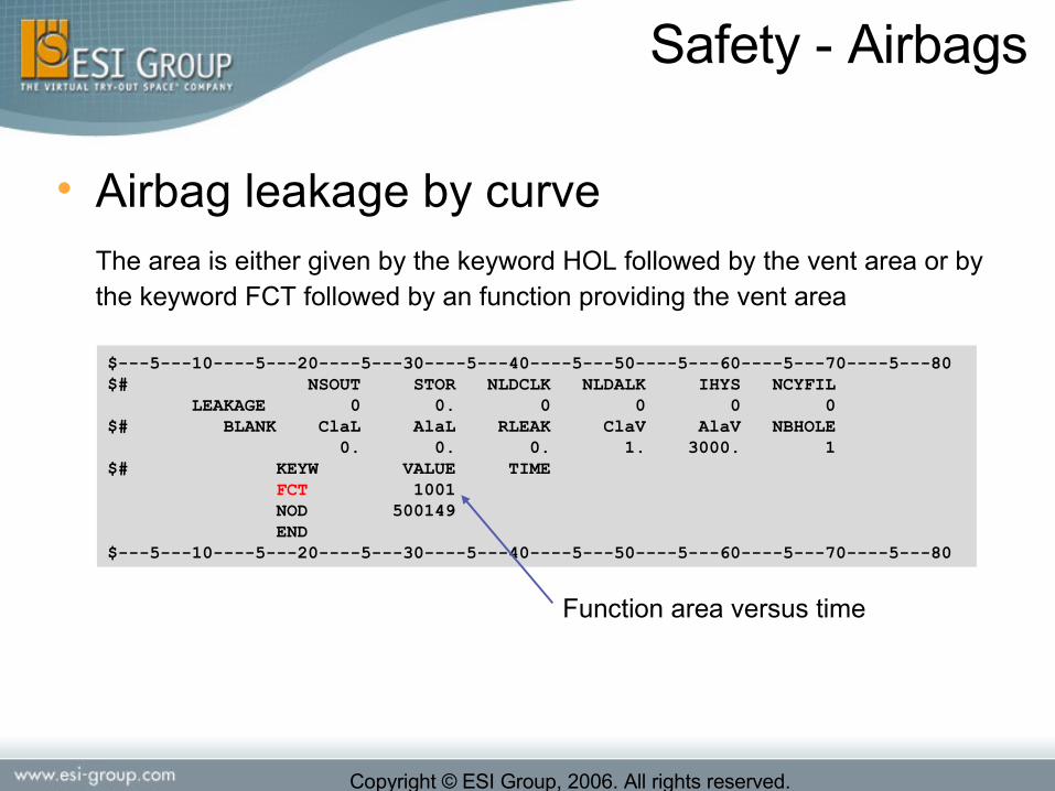
• Airbag leakage by curveThe area is either given by the keyword HOL followed by the vent area or by the keyword FCT followed by an function providing the vent area
$---5---10----5---20----5---30----5---40----5---50----5---60----5---70----5---80$# NSOUT STOR NLDCLK NLDALK IHYS NCYFIL LEAKAGE 0 0. 0 0 0 0$# BLANK ClaL AlaL RLEAK ClaV AlaV NBHOLE 0. 0. 0. 1. 3000. 1$# KEYW VALUE TIME FCT 1001 NOD 500149 END$---5---10----5---20----5---30----5---40----5---50----5---60----5---70----5---80
Function area versus time

Copyright © ESI Group, 2006. All rights reserved.
Safety - Airbags
• Damping based on elements (Simplified external Aerodynamics)
DAMP / Card but for Airbags purposes
Damping computed by faces adds an air drag force to each selected surface element
Fk that is proportional to the area Ak of the element and to the relative
velocity vk squared, i.e.
$---5---10----5---20----5---30----5---40----5---50----5---60----5---70----5---80DAMP / 0 12.0 0. 100.0 0 1NAME Nodal Damping 1$ Drag Coef. Density surrounding air 1.1 0.13E-08 PART 5001 5002 END$---5---10----5---20----5---30----5---40----5---50----5---60----5---70----5---80

Copyright © ESI Group, 2006. All rights reserved.
Safety - Sliprings
• Slipring lock in case of missing left or right side elements • Until PC v2005.1, a runtime error is produced if the
last element on one side of a slipring is reached. • In v2006, the slipring is locked and INFO is
issued.by default in this case.• could be deactivated
• Slipring advanced friction • FRICT / Type 1 (Standard Coulomb)• FRICT / Type 3 (Velocity dependent)

Copyright © ESI Group, 2006. All rights reserved.
Safety – MADYMO Coupling
• Unit Scale factor : No need anymore to build up a PAMCRASH model in “m k s” unit system• The UNIT Card must be defined in the PAM-CRASH input
• From V2006 all Madymo coupling versions are special versions (2006.0_Madymo)
• Supported versions:• Linux ia32• Linux ia64
• HP-UX ia64
Copyright © ESI Group, 2006. All rights reserved.
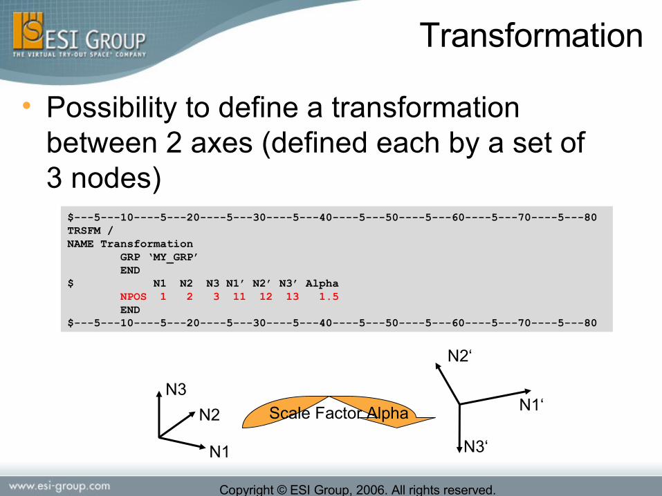
• Possibility to define a transformation between 2 axes (defined each by a set of 3 nodes)
$---5---10----5---20----5---30----5---40----5---50----5---60----5---70----5---80TRSFM / NAME Transformation GRP ‘MY_GRP’ END$ N1 N2 N3 N1’ N2’ N3’ Alpha NPOS 1 2 3 11 12 13 1.5 END$---5---10----5---20----5---30----5---40----5---50----5---60----5---70----5---80
N3
N2
N1 N3‘
N2‘
N1‘Scale Factor Alpha
Transformation
Copyright © ESI Group, 2006. All rights reserved.
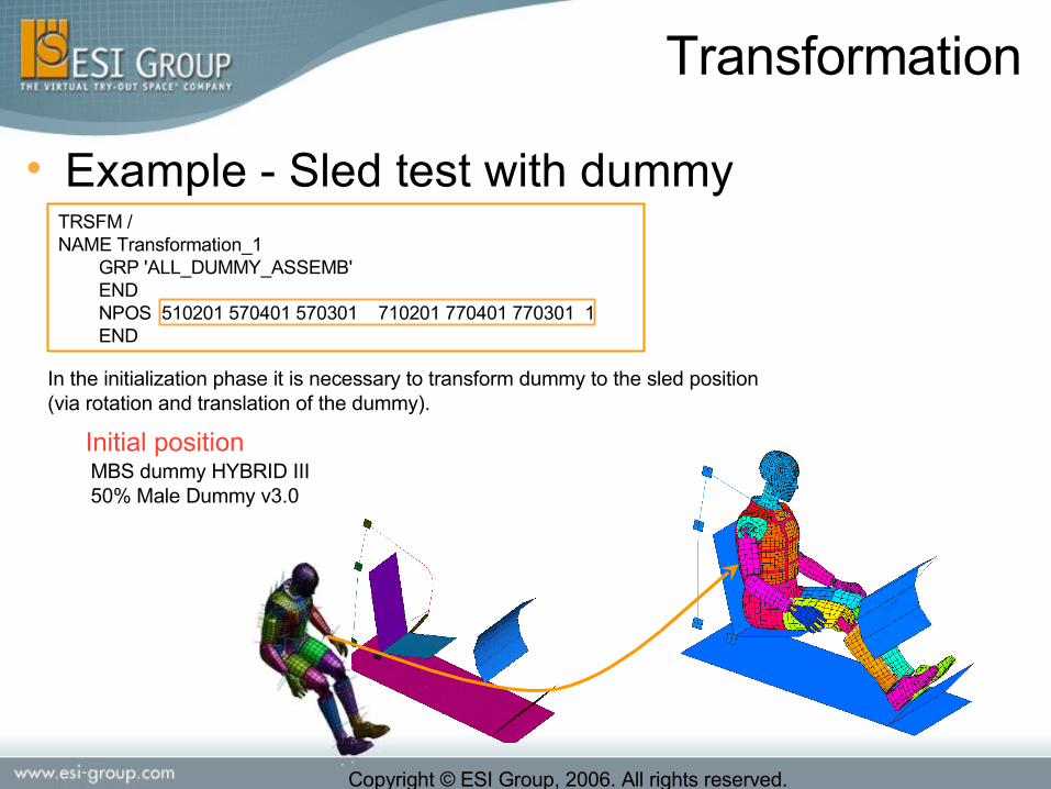
• Example - Sled test with dummyTRSFM / NAME Transformation_1 GRP 'ALL_DUMMY_ASSEMB' END NPOS 510201 570401 570301 710201 770401 770301 1 END
MBS dummy HYBRID III 50% Male Dummy v3.0
In the initialization phase it is necessary to transform dummy to the sled position (via rotation and translation of the dummy).
Initial position
Transformation

Copyright © ESI Group, 2006. All rights reserved.
• Reaction forces on a node with 3D BCS (Support for XXX3D)
$---5---10----5---20----5---30----5---40----5---50----5---60----5---70----5---80BOUNC / 1 100111 NAME Fixed along the X direction$ NODE IFUN1 IFUN2 IFUN3VEL3D / 1 0 8 9 0.0 1.0 1.0NAME Imposed velocity$SECFO / 1SUPPORT 0NAME Reaction force NOD 1 END$---5---10----5---20----5---30----5---40----5---50----5---60----5---70----5---80
Output

Copyright © ESI Group, 2006. All rights reserved.
Output
• Dynamic mass scaling in the output and THP file TCTRL /
INITIAL 0.0 NODAL YES DYNA_MASS_SCALE 7.0000e-4 10. 0END_TCTRLIn time 0.0 ms
In time 37.5 ms
Result of the test – Part Dynamic Mass ScalingResult of the test – Part Dynamic Mass ScalingDefo-element-left
Dynamic Mass Scaling of Defo-element-left
Part Dynamic Mass Contour

Copyright © ESI Group, 2006. All rights reserved.
• Energy contour output:• internal and hourglass for shells and solids
• RBODY connectivity's stored in DSY file• On by default, could be switched off• Negative RBODY ID is used as PART ID• No DSY format change (compatible with 3rd party postprocessor's)
RBODY with COG
Output

Copyright © ESI Group, 2006. All rights reserved.
• Improvements for stiffness scaling diagnostics• Output for DSY
Contour output: Stiffness scale per element(last state with displacement scale=0)
Output

Copyright © ESI Group, 2006. All rights reserved.
Licensing
• Reviewing and simplifying Packages
• SLEEP Function will free the FlexLM tokens
• Possible of encryption of NODE and PARTs
Copyright © ESI Group, 2006. All rights reserved.
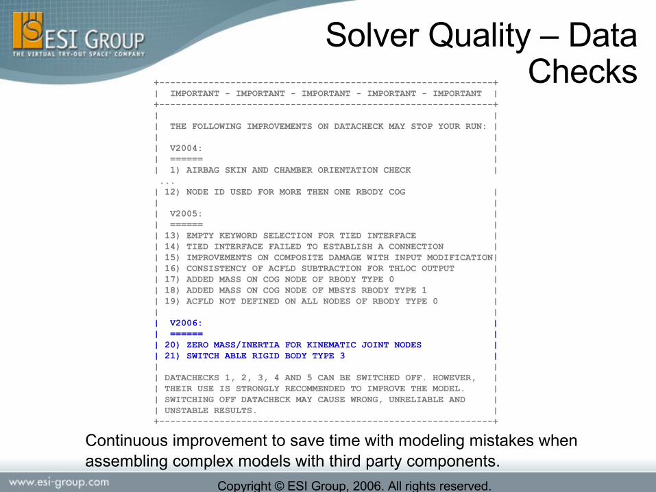
Solver Quality – Data Checks
Continuous improvement to save time with modeling mistakes when assembling complex models with third party components.
+-------------------------------------------------------------+| IMPORTANT - IMPORTANT - IMPORTANT - IMPORTANT - IMPORTANT |+-------------------------------------------------------------+| || THE FOLLOWING IMPROVEMENTS ON DATACHECK MAY STOP YOUR RUN: || || V2004: || ====== || 1) AIRBAG SKIN AND CHAMBER ORIENTATION CHECK | ...| 12) NODE ID USED FOR MORE THEN ONE RBODY COG || || V2005: || ====== || 13) EMPTY KEYWORD SELECTION FOR TIED INTERFACE || 14) TIED INTERFACE FAILED TO ESTABLISH A CONNECTION || 15) IMPROVEMENTS ON COMPOSITE DAMAGE WITH INPUT MODIFICATION|| 16) CONSISTENCY OF ACFLD SUBTRACTION FOR THLOC OUTPUT || 17) ADDED MASS ON COG NODE OF RBODY TYPE 0 || 18) ADDED MASS ON COG NODE OF MBSYS RBODY TYPE 1 || 19) ACFLD NOT DEFINED ON ALL NODES OF RBODY TYPE 0 || || V2006: || ====== || 20) ZERO MASS/INERTIA FOR KINEMATIC JOINT NODES || 21) SWITCH ABLE RIGID BODY TYPE 3 || || DATACHECKS 1, 2, 3, 4 AND 5 CAN BE SWITCHED OFF. HOWEVER, || THEIR USE IS STRONGLY RECOMMENDED TO IMPROVE THE MODEL. || SWITCHING OFF DATACHECK MAY CAUSE WRONG, UNRELIABLE AND || UNSTABLE RESULTS. |+-------------------------------------------------------------+

Copyright © ESI Group, 2006. All rights reserved.
Datacheck
• Zero Mass/Inertia used for KJOINT will stop the run• Many stability problems are caused by this input error• A WARNING is issued already in v2005 (but often ignored)• To avoid runtime ERROR termination, it was promoted from
WARNING to ERROR • Sorry, may cause inconvenience for KJOINT nodes which are
used in BOUNC. But other solution difficult because of DMP.
• RBODY Type 3 is not allowed to be defined switch able• Conservation of the following properties are incompatible with
switch able RBODY type 3• Mass conservation• Kinetic energy conservation• Acceleration field loading (i.e. Gravity)
Copyright © ESI Group, 2006. All rights reserved.
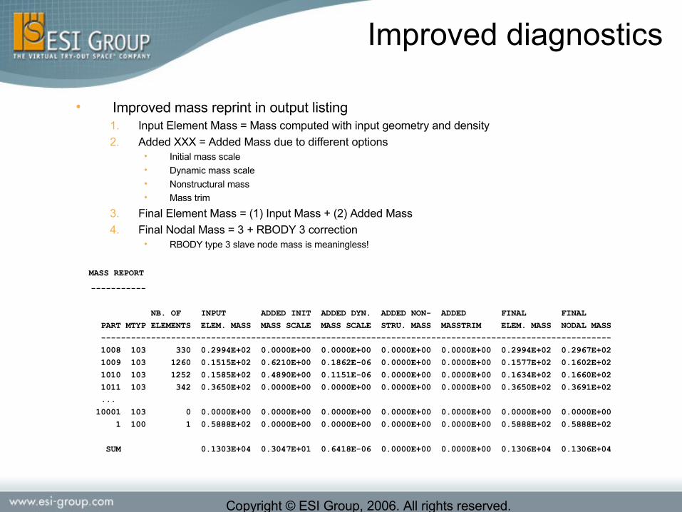
Improved diagnostics
• Improved mass reprint in output listing1. Input Element Mass = Mass computed with input geometry and density
2. Added XXX = Added Mass due to different options• Initial mass scale• Dynamic mass scale• Nonstructural mass• Mass trim
3. Final Element Mass = (1) Input Mass + (2) Added Mass
4. Final Nodal Mass = 3 + RBODY 3 correction• RBODY type 3 slave node mass is meaningless!
MASS REPORT -----------
NB. OF INPUT ADDED INIT ADDED DYN. ADDED NON- ADDED FINAL FINAL
PART MTYP ELEMENTS ELEM. MASS MASS SCALE MASS SCALE STRU. MASS MASSTRIM ELEM. MASS NODAL MASS
------------------------------------------------------------------------------------------------------
1008 103 330 0.2994E+02 0.0000E+00 0.0000E+00 0.0000E+00 0.0000E+00 0.2994E+02 0.2967E+02
1009 103 1260 0.1515E+02 0.6210E+00 0.1862E-06 0.0000E+00 0.0000E+00 0.1577E+02 0.1602E+02
1010 103 1252 0.1585E+02 0.4890E+00 0.1151E-06 0.0000E+00 0.0000E+00 0.1634E+02 0.1660E+02
1011 103 342 0.3650E+02 0.0000E+00 0.0000E+00 0.0000E+00 0.0000E+00 0.3650E+02 0.3691E+02
...
10001 103 0 0.0000E+00 0.0000E+00 0.0000E+00 0.0000E+00 0.0000E+00 0.0000E+00 0.0000E+00
1 100 1 0.5888E+02 0.0000E+00 0.0000E+00 0.0000E+00 0.0000E+00 0.5888E+02 0.5888E+02
SUM 0.1303E+04 0.3047E+01 0.6418E-06 0.0000E+00 0.0000E+00 0.1306E+04 0.1306E+04

Copyright © ESI Group, 2006. All rights reserved.
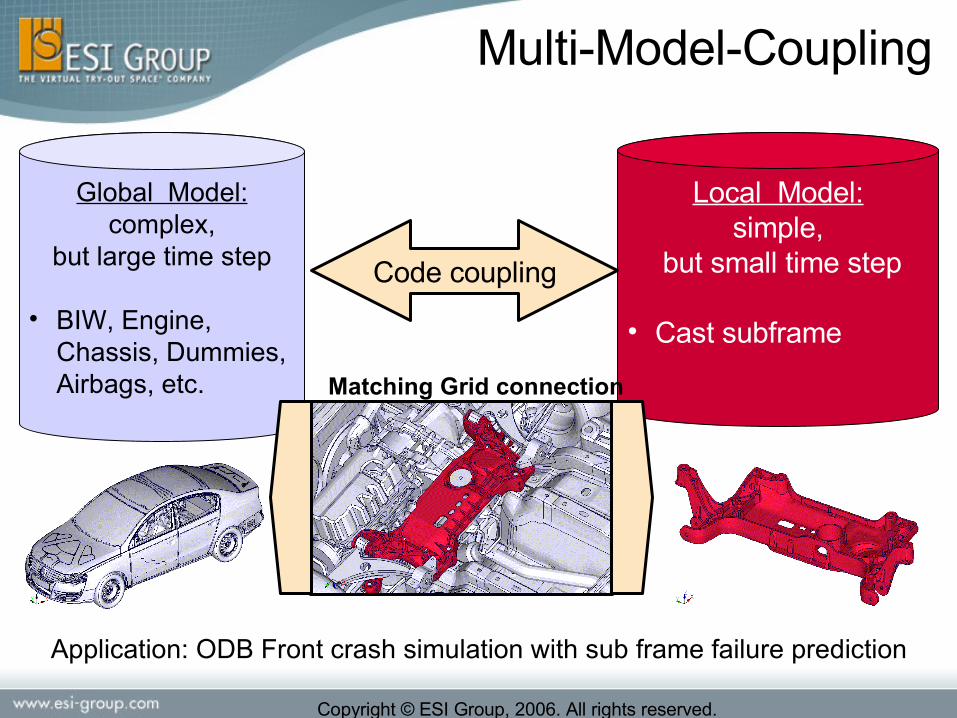
Multi-Model-Coupling
• Failure prediction requires extensively refined solid element models in order to represent :• the actual geometry (e.g. of die-cast
structures, local joints etc.)
• the local stress state during the necking phase of ductile materials
• Aim is to couple a refined (local) model with a standard (global) model for efficient simulation
Copyright © ESI Group, 2006. All rights reserved.
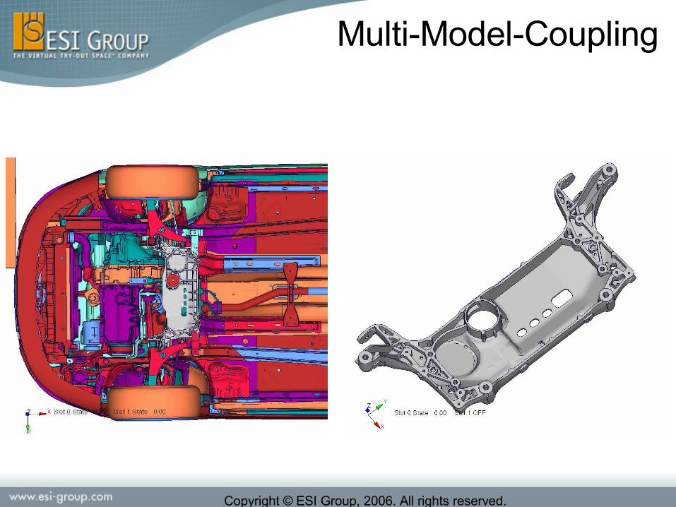
Global Model:complex,
but large time step
• BIW, Engine, Chassis, Dummies, Airbags, etc.
Local Model:simple,
but small time step
• Cast subframe
Code coupling
Application: ODB Front crash simulation with sub frame failure prediction
Matching Grid connection
Multi-Model-Coupling
Copyright © ESI Group, 2006. All rights reserved.
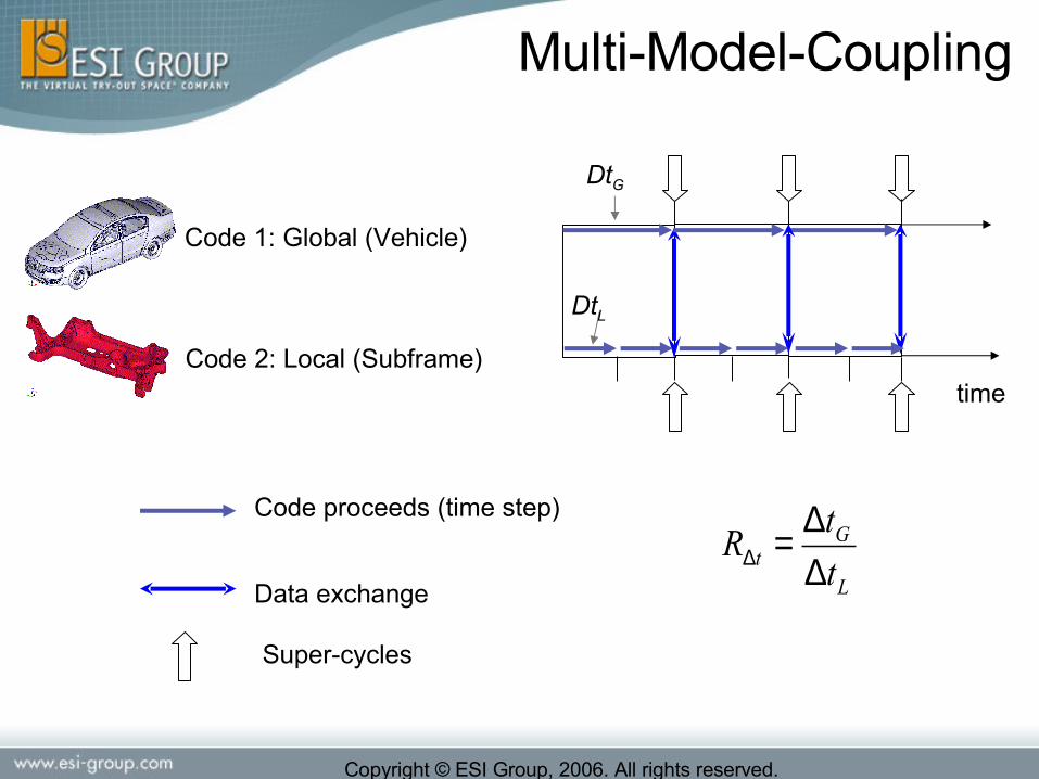
Code proceeds (time step)
Data exchange
Code 1: Global (Vehicle)
Code 2: Local (Subframe)time
Super-cycles
DtG
DtL
L
Gt t
tR
∆∆=∆
Multi-Model-Coupling

Copyright © ESI Group, 2006. All rights reserved.
Car Model:879,000 ElementsTime Step: 1μs
Subframe (65k-Model):65,000 TET10-ElementsTime Step: 0.1μs
Time step ratio: RDt = 10Local model element fraction: fL = 7.4%
+
Multi-Model-Coupling

Copyright © ESI Group, 2006. All rights reserved.
• Example Input (Contact Intermodule)$---5---10----5---20----5---30----5---40----5---50----5---60----5---70----5---80CPCTRL/SUBCYCLE_ECL 10 # to activate the multi time-scaling (10 optional limit) END_CPCTRL$MODULE/ 1NAME x1INCLU / …END_MODULE$MODULE/ 2NAME x2INCLU / …END_MODULE$CNTAC / 10 33…MOD 1 GRP ‘…' ENDEND_MODMOD 2 PART … ENDEND_MOD$---5---10----5---20----5---30----5---40----5---50----5---60----5---70----5---80
Only For contact 33 and 34
- Remove intial penetration possible only the the method 2
- Eroding contact also available
Multi-Model-Coupling

Copyright © ESI Group, 2006. All rights reserved.
• Example Input (Matching Grid)$---5---10----5---20----5---30----5---40----5---50----5---60----5---70----5---80CPCTRL/SCALEF_MGRID 0.1 # penalty stiffness scale factor (0.1 = default)END_CPCTRL$MGRID / 1 5.0e-3NAME Interface1MOD 1 NOD ... ENDEND_MODMOD 2 NOD ... ENDEND_MODEND_MGRID$---5---10----5---20----5---30----5---40----5---50----5---60----5---70----5---80
Multi-Model-Coupling

Copyright © ESI Group, 2006. All rights reserved.
• Find best (economic) process distribution:
!MinNTT tCPUElapsed
AccumElapsed == ElapsedT
tCPUN
( )8
12
20
=
=
=
GCPU
LCPU
tCPU
N
N
NOptimum distribution:
AccumElapsedT
tCPUN
Multi-Model-Coupling
Copyright © ESI Group, 2006. All rights reserved.
Multi-Model-Coupling

Copyright © ESI Group, 2006. All rights reserved.
Similar deformations observed
Crash duration
Multi-Model PAMCRASH: With MMC R∆t = 10
Std PAMCRASH: Without MMC
0 120 ms
Multi-Model-Coupling

Copyright © ESI Group, 2006. All rights reserved.
• Compare elapsed times (with/without MMC) after 120ms
Coupled front crash run (120ms) is completed after 22.5 hoursThe same job without MMC would take 113.5 hours
Com
putation time reduced by
Factor 5 !!!
Multi-Model-Coupling

Copyright © ESI Group, 2006. All rights reserved.
• Other industrial example (front car with head impact)• For a 300 000 / 400 000 elements global model
(1µs)• Submodel :
• 40 000 elements ( ƒl about 10%)
• 0.1 µs (R∆t = 10)
12 CPUs (8 for the local and 4 for the global) are enough to reach a speedup of 3.5
Multi-Model-Coupling
Copyright © ESI Group, 2006. All rights reserved.
Version 2006
FPM-
Implicit
Copyright © ESI Group, 2006. All rights reserved.
FPM
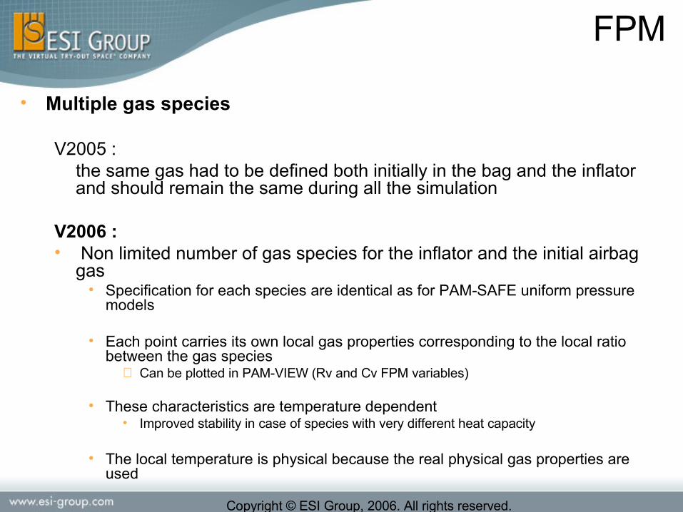
• Multiple gas species
V2005 : the same gas had to be defined both initially in the bag and the inflator and should remain the same during all the simulation
V2006 :• Non limited number of gas species for the inflator and the initial airbag
gas• Specification for each species are identical as for PAM-SAFE uniform pressure
models
• Each point carries its own local gas properties corresponding to the local ratio between the gas species
⇒ Can be plotted in PAM-VIEW (Rv and Cv FPM variables)
• These characteristics are temperature dependent• Improved stability in case of species with very different heat capacity
• The local temperature is physical because the real physical gas properties are used

Copyright © ESI Group, 2006. All rights reserved.
FPM
• Example
Initial gas : Rv = 290
Inflow gas : Rv = 234
Inflator hole

Copyright © ESI Group, 2006. All rights reserved.
FPM
• Perspectives (planned for v2007)• Leakage area obstruction by contact
interfaces
• Chained simulations with CFD analysis tools for the inflator flow and chemistry
• Capability for FPM to read and process the information at inflator nozzle
• Thermal transfer between the gas and the inflator and the casing

Copyright © ESI Group, 2006. All rights reserved.
Implicit
Full Static Linear Capabilities
-Full element libaries (1D, 2D 3D)-RBE2 (Rigid bodies, Hinges)-MPC-PLINK-Skewed frame-Prescribed Displacement BC-Major static loading cases: surface, volume, point, heat.-Multi-loads/Multi-SubCases-Dedicated results file
20062005
Static NL Capabilities
-Efficient Contact-Large displacement-Elasto-plasticity-NL materials-Buckling
Vibration
-Modes-Modal synthesis
Large-Scale Structural DMP Solution
TEAM UP
SPECIFICATION
2007
Roadmap
Copyright © ESI Group, 2006. All rights reserved.
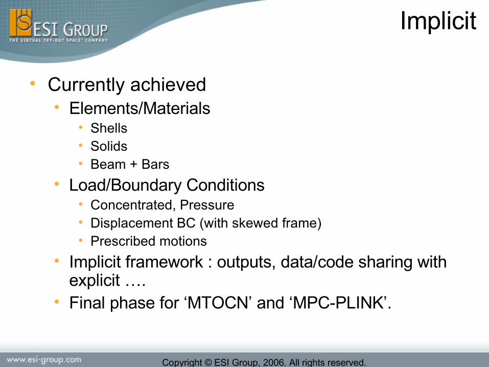
• Currently achieved• Elements/Materials
• Shells• Solids• Beam + Bars
• Load/Boundary Conditions• Concentrated, Pressure• Displacement BC (with skewed frame)• Prescribed motions
• Implicit framework : outputs, data/code sharing with explicit ….
• Final phase for ‘MTOCN’ and ‘MPC-PLINK’.
Implicit

Copyright © ESI Group, 2006. All rights reserved.
• Plan for v2006 (end of the year)• Explicit/Implicit Chaining
• through existing PICKING option
• Constant value in Imposed Displacement (DIS3D)• Constant value in Concentrated Load (CONLO)• MPC PLINK option with Material 224 • Section force output• Pressure on Beam• TIED• 10-Node Tetra• Body Force (Gravity, base motion …)
Implicit

Copyright © ESI Group, 2006. All rights reserved.
Conclusion
Version 2006 available this summer (July 2006)
Copyright © ESI Group, 2006. All rights reserved.
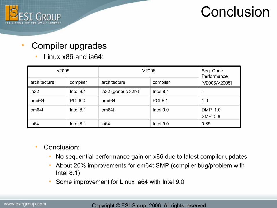
• Compiler upgrades• Linux x86 and ia64:
• Conclusion:• No sequential performance gain on x86 due to latest compiler updates• About 20% improvements for em64t SMP (compiler bug/problem with
Intel 8.1)• Some improvement for Linux ia64 with Intel 9.0
DMP 1.0
SMP: 0.8
Intel 9.0em64tIntel 8.1em64t
0.85Intel 9.0ia64Intel 8.1ia64
PGI 6.1
Intel 8.1
compiler
PGI 6.0
Intel 8.1
compiler architecturearchitecture
1.0amd64amd64
-ia32 (generic 32bit)ia32
Seq. Code Performance
[V2006/V2005]
V2006v2005
Conclusion

Copyright © ESI Group, 2006. All rights reserved.
Performance - Cluster interconnects
• High end interconnect• More and more x86 linux clusters are
shipped with high end interconnect• Myrinet• Infiniband
• V2006 supports:• Lam (6.5.9, 7.0.6, 7.1.1) – ethernet• Mpich-gm – myrinet• Topspin – infiniband
• HPmpi – ethernet, myrinet, infiniband• Scali – ethernet, myrinet, infiniband
Conclusion

Copyright © ESI Group, 2006. All rights reserved.
Conclusion

![10 Strategies [4color WEB] v2006.indd - Research Wizard](https://static.fdocuments.us/doc/165x107/62038e61da24ad121e4ac9c6/10-strategies-4color-web-v2006indd-research-wizard.jpg)