Recent development of 2G HTS coils and quench detection ... · SuperPower, Inc. is a subsidiary of...
14
superior performance. powerful technology. SuperPower, Inc. is a subsidiary of Royal Philips Electronics N.V. Recent development of 2G HTS coils and quench detection methods Yi-Yuan Xie, Maxim Marchevsky, Venkat Selvamanickam, Drew Hazelton, and John Dackow EUCAS 2009, Sept. 13-17, 2009 - Dresden, Germany
Transcript of Recent development of 2G HTS coils and quench detection ... · SuperPower, Inc. is a subsidiary of...

superior performance.powerful technology.
SuperPower, Inc. is a subsidiary of Royal Philips Electronics N.V.
Recent development of 2G HTS coils and quench detection methods
Yi-Yuan Xie, Maxim Marchevsky, Venkat Selvamanickam, Drew Hazelton, and John Dackow
EUCAS 2009, Sept. 13-17, 2009 - Dresden, Germany
EUCAS ’09, Sept 13-17, 2009, Dresden, Germany 2
SuperPower’s 2G HTS wire is based on high throughput processes & superior substrate
YBCO
LaMnO3
MgO (IBAD + Epi layer)
Al2O3
100 nm
Y2O3
Hastelloy C-276
YBCO
LaMnO3
MgO (IBAD + Epi layer)
Al2O3
100 nm100 nm100 nm
Y2O3
Hastelloy C-276
2 μm Ag
20μm Cu
20μm Cu50μm Hastelloy substrate
1 μm YBCO - HTS (epitaxial)~ 30 nm LMO (epitaxial)
~ 30 nm Homo-epi MgO (epitaxial)~ 10 nm IBAD MgO
< 0.1 mm
• High throughput is critical for low-cost 2G wire and to minimize capital investment• SuperPower’s 2G wire is based on high throughput IBAD MgO and MOCVD
processes• Use of IBAD as buffer template provides the choice of any substrate• Advantages of IBAD are high strength, low ac loss (non-magnetic, high resistive
substrates) and high engineering current density (ultra-thin substrates)

EUCAS ’09, Sept 13-17, 2009, Dresden, Germany
IBAD-MgO based MOCVD-2G HTS wires produced in kilometer length
3
• Minimum current (Ic) = 282 A/cm over 1065 m • New world record: Ic × Length = 300,330 A-m• Minimum current (Ic) = 282 A/cm over 1065 m • New world record: Ic × Length = 300,330 A-m
Kilometer Long 2G HTS Wires
0
50
100
150
200
250
300
350
400
450
0 100 200 300 400 500 600 700 800 900 1000 1100
Position (m)
Ic (A
/cm
-w)
Aug-08Aug-08
Jul-08
77 K, Ic measured every 5 m using continuous dc currents over entire tape width of 12 mm (not slit)

EUCAS ’09, Sept 13-17, 2009, Dresden, Germany
Excellent in-field performance make a wide range of real-world applications possible
0 5 10 15 20 25 30 350.025
0.25
2.5
25
250
1E-3
0.01
0.1
1
10
I c(B)/I
c(77K
,0T)
J e (KA/
cm2 )
Magnetic Field B (Tesla)
Ic(B//ab)/Ic(77K,0T) - 4.2K Ic(B//c)/Ic(77K,0T) - 4.2 K Ic(B//c)/Ic(77K,0T) - 14 K Ic(B//c)/Ic(77K,0T) - 22 K Ic(B//c)/Ic(77K,0T) - 33K Ic(B//c)/Ic(77K,0T) - 50K Ic(B//c)/Ic(77K,0T) - 65 K Ic(B//c)/Ic(77K,0T) - 72K Ic(B//c)/Ic(77K,0T) - 77K
BSCC
O 77K, B//C
High Temp, Low Fields:•Cable•SFCL •Transformer •Motor/generator•Plasma Confinement•Xal Growth Magnet•Magnetic separation
Medium Temp, Medium Fields:•Motor/generator•Plasma Confinement•Xal Growth Magnet•Maglev•SMES
Low Temp, High Fields:•SMES•High-Field MRI•High-Field Insert•NMR
* Je is calculated based on Ic (77 K, 0T) = 100 A/4 mm (surr. Cu stabilized) and scaling factors measured by D. Larbalestier, et al at FSU and E. Barzi, et al. of Fermi Lab.
Low Field
High Field Ultra-High Field
Medium
Field

EUCAS ’09, Sept 13-17, 2009, Dresden, Germany
In 2007, we demonstrated a world record high-field magnet
SuperPower coil tested in NHMFL’s unique, 19-tesla, 20-centimeter wide-bore, 20-megawatt Bitter magnet
05
1015202530
0 50 100 150 200 250
Current (A)C
entr
al F
ield
(T)
19T background self field
26.8 T @ 175 A
9.81 T @ 221 A
78 A in 4 mm width (77 K, self field)
Average Ic of wires in coil
~ 462 m2G wire length used
12 (6 x double)# of Pancakes
~ 87 mmWinding OD
19.1 mmWinding ID
9.5 mm (clear)Coil ID
Coil tested by H. Weijers, D. Markewicz, & D. Larbalestier, NHMFL, FSU
0.73 T generated by coil at 77 K

EUCAS ’09, Sept 13-17, 2009, Dresden, Germany
2008: Zr doping was demonstrated in MOCVD to achieve dramatic improvements in in-field performance
Data from Y. Zhang, M. Paranthaman, A. Goyal, ORNL
77K, 1 T0
50
100
150
200
250
300
350
400
450
-20 0 20 40 60 80 100 120
Angle between field and tape (degrees)
Ic (A
/cm
)
3.5 micron SmYBCO2.8 micron GdYBCO
3.3 micron Zr:GdYBCO
150
200
250
300
350
400
450
500
550
-20 0 20 40 60 80 100 120Angle (deg)
2007: 2.8 μm (GdY)BCO
2008: 3.15 μm Zr:(GdY)BCO
2008: 3.33 μm Zr:(GdY)BCO
• 67% increase in minimum Ic to 267 A/cm corresponds to Je of 41,000 A/cm2 (no copper)
• 88% increase in Ic (B ⊥ tape) to 340 A/cm corresponds to Je of 52,300 A/cm2 (no copper)
• 97% increase in minimum Ic to 186 A/cm corresponds to Je of 28,500 A/cm2 (no copper)
• 85% increase in Ic (B ⊥ tape) to 229 A/cm corresponds to Je of 35,200 A/cm2 (no copper)
65 K, 3 T
In 2009, Zr-doping chemistry successfully transferred to production line

EUCAS ’09, Sept 13-17, 2009, Dresden, Germany
Two coils made with Zr-doped 2G wire
Identical size, same quantity of Zr-doped wire with similar critical current performance at 77 K, zero field.
7
Repeatable enhanced coil performance demonstrated with Zr-doped 2G wire
Repeatable enhanced coil performance demonstrated with Zr-doped 2G wire

EUCAS ’09, Sept 13-17, 2009, Dresden, Germany
Third coil made with high amperage, undoped wire
8
Coil ID 12.7 mm (clear)Winding ID 19.1 mmWinding OD ~ 84 mmCoil Height ~ 73.6 mm# of Pancakes 16 (8 x double)2G wire used ~ 600 m# of turns ~ 3696Coil Je ~155.3 A/mm2 @
100ACoil constant ~ 51.8 mT/AWire Ic (77 K, sf) 120 A – 180 A
Insert coil tested in NHMFL’sunique, 20 T, 20 cm wide-bore, Bitter magnet
Patrick Noyes, Ulf Trociewitz, Huub WeijersDenis Markewicz, David Larbalestier

EUCAS ’09, Sept 13-17, 2009, Dresden, Germany
Performance of all three coils exceeded 2T at 65 K
• At 65 K: 2.49 T in self field and 4.6 T in 3 T background field• Achieved similar 65 K field with Zr-doped 2G wire even with substantially lower
zero-field Ic, less wire and larger bore coil.
• At 65 K: 2.49 T in self field and 4.6 T in 3 T background field• Achieved similar 65 K field with Zr-doped 2G wire even with substantially lower
zero-field Ic, less wire and larger bore coil. 9
Performance parameter of third coil
Temperature K 4.2 65 77
Coil Ic - self field A 201.9 48.0 26.8
Amp Turns @ Ic- self field A-turns ~ 746,222 ~ 177,408 ~ 99,052
Je @ Ic, self field A / mm2 313.5 74.5 41.6Central field – self field T 10.410.4 2.492.49 1.391.39
Background field T 19.89 3.0 1.0Coil Ic in background axial field A 144 31 18Amp Turns @ Ic in background field
A-turns ~ 532,224 ~ 114,576 ~ 66,528
Je @ Ic, in background axial field A / mm2 223.6 48.1 28.0
Total Central Field – in background field (axial)
T 27.427.4 4.604.60 1.931.93

EUCAS ’09, Sept 13-17, 2009, Dresden, Germany
2G HTS high-field magnets is one of the most promising future applications. Effective prevention of quenches in these coils is crucial for their reliable operation.
Quench detection in HTS wire is a serious engineering problem. This is due to a very slow (0.1 – 1 cm/s) normal phase propagation velocity (103-104 times less than in LTS!), resulting in a formation of the localized hotspots.
Traditionally, individual voltage monitoring in the magnet sub-sections is used to detect quenches. Those hotspots are hard to detect: significant local heating occurs there prior to the surrounding region transitioning the normal state and becoming resistive.
Quench detection in 2G HTS coil

EUCAS ’09, Sept 13-17, 2009, Dresden, Germany
I0I0
Zero resistance, same part geometry: equal distribution of the currents
V0 V0
New method of quench detectionNew wire configuration is proposed to be used to wind coils. The 2G wire is sub-divided in two parts of equal width along the entire length, except for the areas adjacent to the current leads
+
⎥⎦⎤
⎢⎣⎡
⎟⎠⎞
⎜⎝⎛ −
−⎟⎠⎞
⎜⎝⎛ −
= −+
awba
awba
aIH c
m
)(2ln)(2ln4
2222
π
Hall Sensor
RI0-ΔII0+ΔI
Resistance onset in one of the parts (creep, flux jump, etc..) leads to re-distribution of the currents
V0 V1
+
Hall Sensor
Hall Sensor reading: 2a: strip width2w: gap widthb± = a (1-( I0±ΔI)2/Ic2)1/2

EUCAS ’09, Sept 13-17, 2009, Dresden, Germany
0 5 10 15 20 250
10
20
30
40
50
60
5 mm
Ic=200 A, I0=70 A Ic=100 A, I0= 50 A Ic=100 A, I0=70 A
Bm (
G)
Δ I (A)
5 mm
2 mm
Theoretical result for the 12 mm-wide tape divided into two strips with various Ic and driving currents:
Readily detectable field of ~10 Gauss should appear in the gap region even for a small (~5-10 A) current imbalance;
Calculation
+
1 0 0 1 2 5 1 5 0 1 7 5 2 0 00
1
2
3
4
5
h e a te r o n h e a te r o f f
V 01 (
μV)
I ( A )
Experiment
V0 V1
Hall Sensor
Small heater contacts with only one side
Ictotal
184 A200 A
Heater onHeater off
Heater on decrease in Ictotal and redistribution of current less than Ictotal

EUCAS ’09, Sept 13-17, 2009, Dresden, Germany
0 5 10 15
40
45
50
55
60
65
130 A 160 A 170 A 180 A 190 A
B (G
)t (s)
In this new method, the effect of local heating is clearly detected, even when current is well below Ic !
Response to heat pulse: Voltage vs. Hall sensor
0 5 10 15-0.05
0.00
0.05
0.10
130 A 160 A 170 A 180 A 190 A
U (
mV)
t (s)
Voltage due to heat pulse is unambiguously detected only when the transport current exceeds Ic_heat.
Magnetic field induction in the slit measured simultaneously during the heat pulse application (offset is due to electrical imbalance of the Hall sensor)
EUCAS ’09, Sept 13-17, 2009, Dresden, Germany
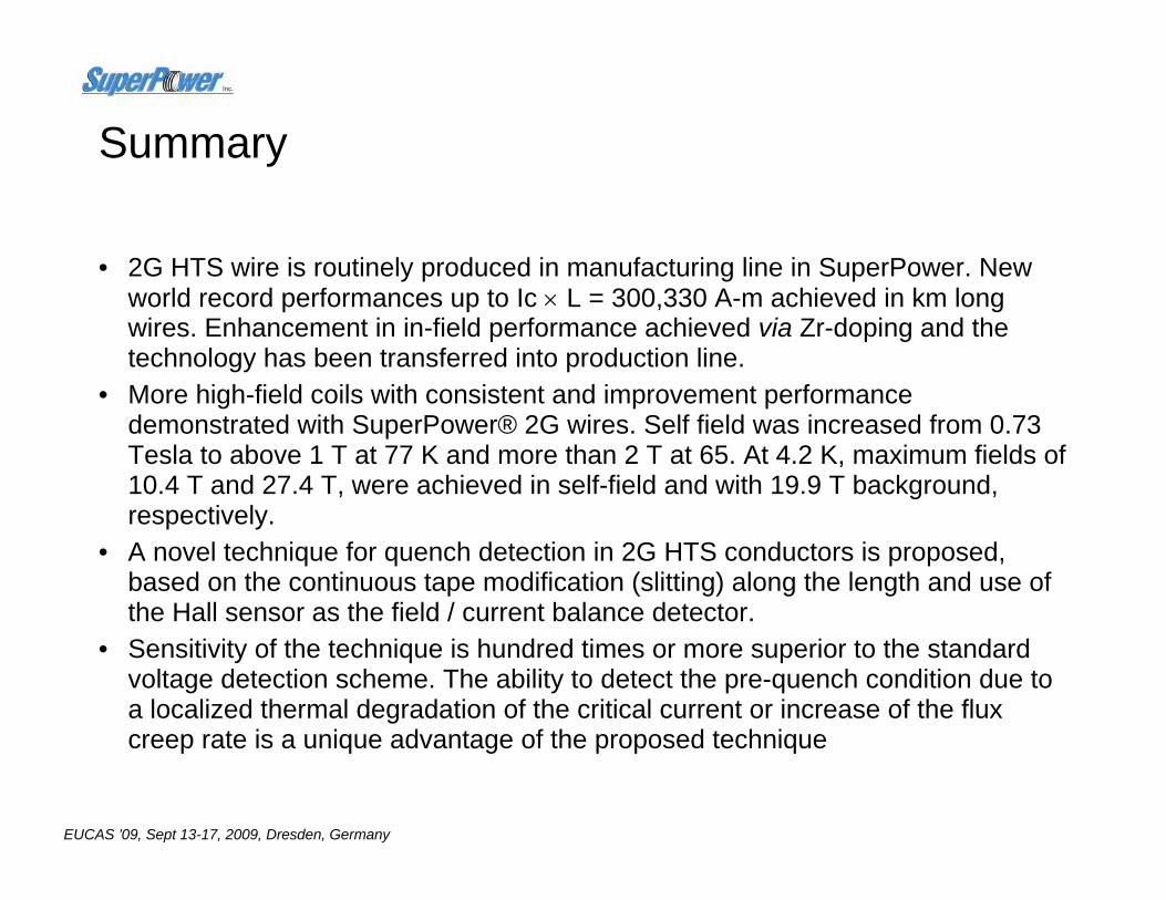
Summary
• 2G HTS wire is routinely produced in manufacturing line in SuperPower. New world record performances up to Ic × L = 300,330 A-m achieved in km long wires. Enhancement in in-field performance achieved via Zr-doping and the technology has been transferred into production line.
• More high-field coils with consistent and improvement performance demonstrated with SuperPower® 2G wires. Self field was increased from 0.73 Tesla to above 1 T at 77 K and more than 2 T at 65. At 4.2 K, maximum fields of 10.4 T and 27.4 T, were achieved in self-field and with 19.9 T background, respectively.
• A novel technique for quench detection in 2G HTS conductors is proposed, based on the continuous tape modification (slitting) along the length and use of the Hall sensor as the field / current balance detector.
• Sensitivity of the technique is hundred times or more superior to the standard voltage detection scheme. The ability to detect the pre-quench condition due to a localized thermal degradation of the critical current or increase of the flux creep rate is a unique advantage of the proposed technique