Recent Advances in Microscale Pumping Technologies: A ...
66
Purdue University Purdue e-Pubs CTRC Research Publications Cooling Technologies Research Center 2-19-2008 Recent Advances in Microscale Pumping Technologies: A Review and Evaluation Brian D. Iverson Birck Nanotechnology Center, School of Mechanical Engineering, and Cooling Technologies Research Center, Purdue University, [email protected] S V. Garimella Purdue University, [email protected] Follow this and additional works at: hp://docs.lib.purdue.edu/coolingpubs is document has been made available through Purdue e-Pubs, a service of the Purdue University Libraries. Please contact [email protected] for additional information. Iverson, Brian D. and Garimella, S V., "Recent Advances in Microscale Pumping Technologies: A Review and Evaluation" (2008). CTRC Research Publications. Paper 89. hp://dx.doi.org/10.1007/s10404-008-0266-8
Transcript of Recent Advances in Microscale Pumping Technologies: A ...

Purdue UniversityPurdue e-Pubs
CTRC Research Publications Cooling Technologies Research Center
2-19-2008
Recent Advances in Microscale PumpingTechnologies: A Review and EvaluationBrian D. IversonBirck Nanotechnology Center, School of Mechanical Engineering, and Cooling Technologies Research Center, Purdue University,[email protected]
S V. GarimellaPurdue University, [email protected]
Follow this and additional works at: http://docs.lib.purdue.edu/coolingpubs
This document has been made available through Purdue e-Pubs, a service of the Purdue University Libraries. Please contact [email protected] foradditional information.
Iverson, Brian D. and Garimella, S V., "Recent Advances in Microscale Pumping Technologies: A Review and Evaluation" (2008).CTRC Research Publications. Paper 89.http://dx.doi.org/10.1007/s10404-008-0266-8

1
Recent advances in microscale pumping technologies: A review and evaluation Brian D. Iverson and Suresh V. Garimella NSF Cooling Technologies Research Center School of Mechanical Engineering and Birck Nanotechnology Center Purdue University 585 Purdue Mall West Lafayette, Indiana 47907-2088 Email: [email protected] ABSTRACT
Micropumping has emerged as a critical research area for many electronics and biological
applications. A significant driving force underlying this research has been the integration of
pumping mechanisms in micro Total Analysis Systems (μTAS) and other multi-functional
analysis techniques. Uses in electronics packaging and micromixing and microdosing systems
have also capitalized on novel pumping concepts. The present work builds upon a number of
existing reviews of micropumping strategies by focusing on the large body of micropump
advances reported in the very recent literature. Critical selection criteria are included for pumps
and valves to aid in determining the pumping mechanism that is most appropriate for a given
application. Important limitations or incompatibilities are also addressed. Quantitative
comparisons are provided in graphical and tabular forms.
KEYWORDS: micropump, microfluidic, fluid delivery, electronics cooling, biofluid
Acknowledgements: The authors acknowledge financial support for this work from members of the Cooling Technologies Research Center (www.ecn.purdue.edu/CTRC), a National Science Foundation Industry/University Cooperative Research Center at Purdue University.

2
1 INTRODUCTION There has been a recent surge in studies exploring micropump technologies, motivated in
part by the need to develop pumping mechanisms for biological fluid handling such as for
polymerase chain reaction (PCR) and Lab-on-a-Chip and micro Total Analysis Systems (μTAS)
(Zhang et al. 2007). Additionally, micropumps are being considered for application in the
cooling of microelectronics as the use of liquid cooling has become increasingly necessary to
alleviate the extremely challenging cooling constraints in these compact systems (Garimella et
al. 2006, Singhal et al. 2004b). A wide variety of technologies exist for pumping liquids while
reducing total pump volume.
Thermal management of electronic components is of increasing concern in the
development of portable and reliable electronic devices. The need to reduce package weight and
volume while increasing the device functionality has received much attention in recent years. Of
the strategies available for thermal management in electronic systems, liquid cooling in
microchannels has the ability to increase power dissipation while also maintaining a small form
factor. Contact and spreading resistances can be reduced by integrating the channels directly on
the back side of common flip-chip designs. Further, by using liquid cooling, the heat generation
and heat rejection components can be separated, releasing the convective surface area for
ultimate heat rejection to the ambient from being constrained by the microprocessor area
(Mahajan et al. 2006). Thus, the heat exchanger in the cooling loop can be placed at any
convenient location in the device. However, the requirement of large pumps to drive the liquid
flow and the associated large pumping power have limited the application of microchannel heat
sinks in space-constrained electronics (Garimella et al. 2006). Innovative micropumping
solutions are thus critical for facilitating wider use of liquid cooling approaches in electronic
systems.
Strategies for the development of cell and biological analysis tools have also exploited
microfluidic devices since they can be used to sample, trap, separate, sort, treat, detect and
analyze biological materials (Andersson and Van den Berg 2003). Microfluidic devices offer
many attractive benefits for biological handling and analysis. For example, reducing device size
also reduces sample requirements and reagent volumes which can reduce overall cost. Test chips
are often disposable which is important for sterility. Using microfluidic chips also allows for a
3
closed system, thus protecting the operator from chemical exposure. The small size
accommodates parallel operations and thereby reduces cell sorting, analysis and treatment times.
Combining different functions on a single microchip is another step toward maintaining a
completely closed system that can be fully automated, reduce contamination, and eliminate
human intervention and error (Wolff et al. 2003). However, for microfluidic devices to
capitalize on all of the above benefits, integration of the fluid pumping mechanism is imperative.
Several extensive reviews of micropump strategies are available (Laser and Santiago
2004, Nguyen et al. 2002, Woias 2005), with some having emphasized specific applications
(Singhal et al. 2004b, Zhang et al. 2007). In the present work, past reviews of micropumps are
not duplicated. Rather, we provide an overview of pumping mechanisms and important new
developments addressed in the recent literature spanning the past few years, and outline the
critical selection criteria for determining which of these mechanisms is appropriate for a given
application. Micropumping needs vary over a wide range from low-power, low-flow-rate to
high-flow-rate, high-back-pressure solutions. Thus, a variety of pump selection criteria are
employed in determining pumping mechanisms suitable for a given application. While the
discussion in the text includes quantitative values, a comprehensive quantitative assessment is
provided in graphical and tabular forms.
We broadly classify micropumps into two main categories, along the lines of
classifications in other reviews:
i. Mechanical displacement micropumps – defined as those that exert oscillatory or
rotational pressure forces on the working fluid through a moving solid-fluid
(vibrating diaphragm, peristaltic, rotary pumps), or fluid-fluid boundary (ferrofluid,
phase change, gas permeation pumps).
ii. Electro- and magneto-kinetic micropumps – defined as those that provide a direct
energy transfer to pumping power and generate constant/steady flows due to the
continuous addition of energy (electroosmotic, electrohydrodynamic,
magnetohydrodynamic, electrowetting, etc.).
Micropumps in the above categories can be further divided into sub-categories based on
their actuation principle. The following two sections describe the basic working principles of the
various kinds of micropumps and valves in the literature. A categorization of the various pump
types is shown in Figure 1. A discussion of these techniques is then provided, wherein we

4
evaluate critical features of various pumps for applicability and sustainability in various
applications. Several illustrative figures have been modified from a previous micropump review
from our group (Singhal et al. 2004b). For a detailed discussion of studies in the literature prior
to 2005, we direct readers to this earlier review.
2 MECHANICAL DISPLACEMENT MICROPUMPING TECHNIQUES Mechanical displacement micropumps use the motion of a solid (such as a gear or
diaphragm) or a fluid to generate the pressure difference needed to move a fluid. Of these,
diaphragm pumps are most common and employ many different actuation mechanisms. They
also incorporate some type of valving for flow rectification.
2.1 Diaphragm displacement pumps As shown schematically in Figure 2a, diaphragm displacement pumps typically are
comprised of a pumping chamber connected to inlet and outlet valves necessary for flow
rectification. As the diaphragm deflects during the expansion stroke, the pumping chamber
expands resulting in a corresponding decrease in chamber pressure. When the inlet pressure is
higher than the chamber pressure, the inlet valve opens and liquid fills the expanding chamber
(Figure 2b). During the compression stroke, the volume of the chamber decreases with the
moving diaphragm, causing the internal pressure to increase whereby liquid is discharged
through the outlet valve (Figure 2c). Many types of actuation mechanisms exist for the vibrating
diaphragm. Piezoelectric, electrostatic, electromagnetic, pneumatic, and thermopnuematic
actuation are among the more common methods. Further, valve types differ widely in the
literature. Dynamic and static valves have been used for flow rectification and can either be
active or passive structures. Diaphragm actuation mechanisms and valve types are explained in
the following subsections.
2.1.1 Piezoelectric Piezoelectric materials generate an internal mechanical stress in the presence of an
applied electric potential, and vice versa. This mechanism is probably the most widely used for
actuating diaphragm micropumps. The piezoelectric material is bonded to, deposited on or
embedded in the diaphragm for actuation and the applied AC voltage drives the expansion and
compression strokes as the signal changes in polarity. Advantages of this actuation method are

5
that relatively large displacement magnitudes and forces are achievable. Distinguishing
characteristics of different piezoelectric micropumps are the chamber geometry, the type of
valves used, the shear orientation used for actuation, and the type of piezoelectric material
selected.
Standard, flat-diaphragm chamber geometries are fabrication friendly; however, they are
less efficient in converting in-plane strain to volumetric deflection as compared to a dome-
shaped diaphragm chamber of the same diameter. Further, dome-shaped diaphragms have a
higher stiffness which manifests in higher resonant frequencies. A novel molding process for
fabricating dome-shaped chambers was developed by Feng and Kim (2005). Their work also
illustrates that larger pressures are exerted for smaller-radii pump chambers which have
corresponding larger curvatures.
In order to obtain flow rectification from the oscillatory motion of the diaphragm, valves
are incorporated into the design of diaphragm pumps. Valves take many forms and can feature
passive or active control. Although a relatively older concept, nozzle-diffuser type fixed-
geometry valves have been investigated in the recent past for specific applications such as drug
delivery as they employ no moving parts (Cui et al. 2007). Piezoelectrically actuated pumps
have become common as they can be fabricated relatively inexpensively, especially when using
low-cost, deformable materials such as polydimethylsiloxane (PDMS) (Kim et al. 2005b).
Recently, modifications to the standard nozzle-diffuser valves that accommodate regions of
vortex circulation (similar to Tesla valves) have been studied for use with piezoelectrically-
actuated diaphragms (Izzo et al. 2007). These and other valve types are addressed in more detail
in section 2.1.9.
Throttling has also been suggested as a potential alternative to conventional valves.
Since the volumetric flow rate is inversely proportional to the fourth power of the channel
hydraulic diameter, small changes in the hydraulic diameter can yield an exploitable modulation
of the volumetric flow rate. In order to modulate the hydraulic diameter of the throttle,
piezoelectrically actuated diaphragms have been used for semi-passive flow control. The design
employed by Tracey et al. (2006) incorporates passive throttle structures in which the hydraulic
diameter is actively changing with the piezoelectric diaphragm. Further, their design can
accommodate actuation of multiple neighboring channels with the same piezoelectric material.

6
Flow output can be connected in parallel or series depending on whether high volume flow rates
or high pressures are desired.
While there is little chance for structural failure of fixed-geometry valves, they do not
always provide the necessary flow rectification for higher flow rates and cannot operate in a bi-
directional mode. Active diaphragm valves that can overcome such shortcomings are also
commonly controlled with piezoelectric diaphragms (Doll et al. 2006). In these scenarios, the
piezoelectrically actuated diaphragms are used not only for the pump chamber but also to open
and close the inlet/outlet valves in sync with the chamber expansion and compression.
A lightweight piezoelectric composite actuator (LIPCA) has been reported as an
improvement to traditional piezoelectric actuators (Nguyen et al. 2006). This oxide-based,
piezoelectric material incorporates carbon or glass and epoxy fabric. Experimental results with a
PDMS diaphragm show that the fractional stroke (displacement per unit length) of the LIPCA is
approximately 0.35% as compared to conventional piezoelectric diaphragms which are normally
associated with values lower than 0.2%. Thus, comparatively larger displacements can be
achieved with this material for the same driving potential.
Novel piezoelectric diaphragm actuation using shear deformation has also recently been
considered in microfluidic applications (Chen et al. 2007). Actuation in this orientation can be
used for droplet ejection and diaphragm pumping applications.
A complete electro-mechanical-fluid coupled model of a piezoelectric-actuated,
diaphragm pump demonstrated that flow rate should not increase continuously with increasing
frequency for high frequencies (Fan et al. 2005). Optimization studies have also been conducted
for both membrane valves and nozzle-diffuser valves using equivalent electrical networks for
representation and modeling in SPICE (Morganti et al. 2005).
2.1.2 Electrostatic Electrostatic actuation employs the use of electrostatic forces generated between
electrodes to drive diaphragm motion (Zengerle et al. 1992). As an electrical voltage is applied
between a counter electrode and the diaphragm membrane, they act as a variable capacitor and
the electrostatic forces generated cause movement of the membrane outward, towards the
counter electrode. Hence, the pressure in the pumping chamber decreases, drawing fluid into the
chamber. When the voltage is removed, the membrane bounces back, which increases the

7
pressure in the pumping chamber, thus expelling the fluid. The capacitance between a pump
diaphragm and a counter electrode (diameter, d) separated by a distance (l) can be calculated by
2
4dCl
επ= . (1)
The force acting to pull the two plates together is
2
2 22
12 8
C dF V Vl l
επ∂= = −
∂ (2)
where V is the potential difference across the plates, and ε is the permittivity.
Electrostatic actuation has received comparatively little attention in the recent micropump
literature. However, an advancement over the typical electrostatic actuation described above has
been considered in which voltage is applied across the liquid working fluid to take advantage of
the higher relative electrical permeability of water/fluids as compared to air (Machauf et al.
2005). The higher the permittivity, the higher are the force and the pumping rate for the same
applied voltage and geometry. Thus, even for relatively large distances between electrodes, the
generated force across the liquid can be large enough to induce pumping. Although not an ideal
design, the experiments of Machauf et al. (2005) showed that approximately 1 μl/min could be
pumped at 50 V (across 63 μm gap) under sub-optimal conditions.
Pumping using electrostatic actuation was developed for a gas chromatograph application
(Astle et al. 2007). Improved understanding of the gas flow in the micropump was one of the
major aims of this work. A four-stage pump operating at 14 kHz provided a flow rate of 3
ml/min and a maximum back pressure of 7 kPa.
2.1.3 Electromagnetic and magnetic The electromagnetic actuation mechanism generally consists of a permanent magnet
attached to a diaphragm and surrounded by a coil. When a current is passed through the coil,
Lorentz forces are produced to deflect the diaphragm due to the interaction of the magnetic field
with the electric field. Advantages of this method are that electromagnetic actuation generally
requires a small voltage (~5 V) and has a simple design of driver electronics as compared to
other mechanisms. This type of micropump has been discussed in the literature for years.
Recently, diaphragm deflections have improved for micropumps with overall size reductions
achieved by integrating the permanent magnet and coils directly into the device (Chang et al.
2007, Su et al. 2005, Yufeng et al. 2006).
8
A permanent magnet cast in PDMS with flow rectification provided by ball valves was
developed by Yamahata et al. (2005b). The conical holes for the ball valves were powder
blasted in glass and the device was fusion-bonded together. The glass construction (valves and
body) is an important feature as it is chemically inert and can be sterilized at high temperatures.
Typically, glass devices do not provide high back pressures which are achieved by large
actuation forces in combination with highly efficient valves. However, a maximum flow rate of
5 ml/min was demonstrated at 30 Hz with a maximum back pressure of 28 kPa for a diaphragm
chamber diameter of 1 cm.
A similar ball-valve-based, magnetically driven micropump was investigated using a
magnet attached to a DC motor, and alternatively using an inductive coil (Pan et al. 2005). A
large reduction in power requirement was demonstrated in the DC motor-driven case (13 mW) as
compared to the coil (500 mW) for comparable flow rates. The ball valves help to limit
backward leakage to less than 1 μl/min for pressures of up to 30 kPa and maximum flow rates of
0.7 to 1 ml/min.
Construction of composite diaphragms in which small magnetic particles are cast directly
into the PDMS have also been developed. In this manner, the diaphragm boundary directly
incorporates the material for actuation by the magnetic field. Nagel et al. (2006) used an iron-
PDMS (Fe-PDMS) composite with less than 10 μm diameter iron particles. Yamahata et al.
(2005c) used a 40% volume fraction of NdFeB powder (average particle size 200 μm) in PDMS
for a membrane stroke of 200 μm. Nozzle-diffuser elements were incorporated for flow
rectification.
Other types of magnetically induced flows have been achieved by exerting attractive
forces between a permanent magnet and steel disks incorporated into pumping and valve
chambers (Haeberle et al. 2007). In this design, the permanent magnet is mounted on a rotating
disk. As the disk rotates and the magnet passes by the static steel disks in the valve and the
pumping chamber diaphragms, the chambers contract and expand in succession. The appeal of
this design is that the only power required to drive this pump is the relatively low power required
for the disk rotation.
Magnetic fluids have emerged as an additional choice for micropump actuation. Fluids
of this type are generally a suspension of magnetic particles in a carrier medium. Sim et al.
(2006) used the response of a magnetic fluid to a field to actuate a parylene diaphragm in a
9
micropump. The salient features of this pump are that at a field of 110 Gauss, the diaphragm
could be deflected by more than 200 μm to provide a pressure of 2.8 kPa. The suspended
magnetic particles, which have an average size of about 100 Å, are coated with a stabilizing
dispersant to prevent agglomeration in the presence of a magnetic field. The suspensions are
stable and preserve their properties despite exposure to extreme temperatures and over long
periods of time.
2.1.4 Thermal Thermal actuation involves the volume expansion or induced stress of a material in
response to applied heat. In the context of diaphragm micropumps, this usually takes the form of
thermopneumatic or shape memory alloy (SMA) actuation. Since these methods rely on the
diffusion of thermal energy, they are limited to low actuation frequencies.
Thermopneumatic actuation occurs when a secondary fluid (separate from the driven
fluid) is heated (usually by a thin film resistive heater) causing it to expand and deflect the pump
diaphragm. The intake stroke (pump chamber expansion) occurs as the heater is deactivated
allowing the secondary fluid to cool and contract. A transparent, cost-effective thermopneumatic
pump using PDMS and nozzle-diffuser elements was developed by Kim et al. (2005a). Usage of
indium tin oxide (ITO) as the conductive heating element provides transparency if desired. For a
diaphragm diameter of 3.5 mm and inlet/outlet lengths of 1.5 mm, a peak flow rate of 78 nl/min
was demonstrated for methanol with an applied pulse of 55 V at 6 Hz.
Thermal expansion also occurs for phase-change materials as opposed to single-phase gas
expansion. Paraffin waxes, also used for transient heat absorption from electronics, have been
employed to actuate a diaphragm pump by exploiting its volume expansion from solid to liquid
as it melts due to resistive heating. Melting temperatures for paraffin can be tailored to lie
between -100 and 150 °C. The material can also be shaped by casting, and is non-toxic. Since it
is a thermal actuator, the actuation frequency is relatively low; however, it can sustain very high
pressures. Boden et al. (2006) used Sigma-Aldrich 76228 with a melting point of 44-48 °C and a
volume expansion of about 10% to obtain flow rates of 74 nl/min and up to 0.2 MPa (0.92 MPa
with clamping) at 0.5 Hz frequency.
Shape memory actuation uses the shape memory effect of TiNi, which involves a phase
transformation between two solid phases: a high-temperature austenite phase and a low-
temperature martensite phase. Martensite is much more ductile than austenite allowing the TiNi

10
to undergo large deformations. Heating above the phase-transformation temperature results in an
austenite phase transition in the TiNi. During this transformation, TiNi assumes its initial shape
if it is not constrained. However, when constrained, it exerts a large force in trying to assume its
initial shape. Shape Memory Alloys (SMAs) are characterized by large recoverable strain
outputs of up to 6-8%. However at high frequencies, SMAs do not cool sufficiently and their
performance suffers. Generally, they operate below 100 Hz.
Recently, larger flow rates of 2.53 ml/s have been achieved for a thin-film TiNi SMA
pump with corresponding velocities of 5 mm/s (Shin et al. 2005). This flow rate represents a
three-order-of-magnitude increase over previously published SMA pump studies. Another SMA
pump with a TiNi(Cu) alloy has demonstrated low temperature actuation (Zhang and Qiu 2006).
In some applications, the working fluid in the pump chamber is to be kept below a specific
temperature in order to not adversely affect the fluid. Using this TiNi(Cu) SMA, actuation
below 290 K is achieved while providing a high diaphragm displacement (6 μm) and relatively
high working frequency (85 Hz).
2.1.5 Pneumatic Pneumatic pumps exploit fluctuations in gas pressure on a diaphragm to effect vibration.
As gas pressure builds on the diaphragm, deflection occurs for the compression stroke.
Pneumatic valves are actuated in a similar manner for flow rectification. Pneumatic driving
forces are commonly employed in a peristaltic actuation sequence as is discussed in more detail
in section 2.1.8.
Diaphragm pumps are generally characterized by a pulsing flow due to the reciprocating
nature of the boundary. A bi-directional, pneumatic diaphragm pump that incorporates a fluidic
capacitor to convert the pulsatile flow into a continuous stream was developed by Inman et al.
(2007). For a pneumatic pressure of 40 kPa, a 2.6 ml/min flow rate was achieved against a 25
kPa back pressure.
2.1.6 Composite / polymer materials Materials selection, to a great extent, distinguishes diaphragm micropumps. Composite
materials have been developed as improved alternatives to some of the commonly used actuation
materials. An ionic polymer-metal composite (IPMC) material was electromechanically
actuated, similar to piezoelectric materials, to create a larger bending deformation (over 1%

11
bending strain) under a low input voltage by (Lee and Kim 2006, Lee et al. 2005). The
manufacturing costs of this composite are stated to be competitive with other actuator
technologies. As compared to piezoelectrically driven diaphragms, IPMCs require significantly
lower input voltages thus making them attractive as a driving mechanism.
Another diaphragm material has been demonstrated to compete well with traditional
diaphragm actuating mechanisms. An electroactive polymer (polyvinylidene fluoride-
trifluoroethylene – PVDF TrFE) has achieved displacements of 21 μm on a 1 mm diameter
diaphragm at 106 V/μm and a driving frequency of 10 Hz (Xu and Su 2005). The unstretched
PVDF films make film processing very simple and the isotropic strain response is amenable to
circular shaped actuators. Further, these materials are characterized by higher strains than are
common in piezoelectric ceramics.
2.1.7 Irreversible Actuation mechanisms in which the induced deflection is irreversible (and hence, not
cyclic) are denoted as irreversible approaches. However, irreversible pumps have many
attractive features despite this limitation. Generally they require no input power for actuation
and, in some cases, can produce large pressures. When maximum portability is required and the
use of electrical networks or power is disallowed, these technologies are particularly suitable.
Ionic polymer particles that swell due to osmotic effects have been demonstrated to be
viable for liquid pumping. The swelling is induced simply by adding water (Good et al. 2007).
Gels also can be engineered to deform under some physical or chemical stimulus and used as an
actuator for irreversible diaphragm deflection (Suzuki 2006).
Thermally responsive pumping has also been achieved through the use of expandable
microspheres. Composites of these microspheres in PDMS have been constructed such that as
the material is heated, the embedded microspheres expand the material up to 270%. Again, the
expansion is irreversible but has been shown to propel nanoliters of flow against 100 kPa back
pressures (Samel et al. 2007a, Samel et al. 2007b). Larger volumes on the order of microliters
have also been moved by buckling the PDMS composite. In instances where the trigger
mechanism is a rise in temperature, these materials are directly applicable since there would be
no transduction or consumption of external energy for actuation.

12
The irreversible actuation principles discussed here are likely to be used only for single-
use, disposable applications.
2.1.8 Peristaltic As the name suggests, these pumps incorporate the peristaltic motion of actuators in
series to generate pumping action. Most of the peristaltic pumps presented in the literature use
three pumping chambers with diaphragms as actuators in series (see Figure 3). Thus they can be
considered a subset of the vibrating diaphragm pumps considered above, and they utilize many
of the same types of transducers (piezoelectric, pneumatic, etc.). When the first diaphragm is
actuated, it restricts the flow to the inlet of the pump. As the second diaphragm is actuated, fluid
is pushed toward the third pumping chamber. Similarly, actuating the third diaphragm in
succession pushes the fluid through the outlet of the pump. In essence, the diaphragms act like
valves that reduce the flow cross section to provide flow directionality. All three diaphragms are
then de-actuated and the sequence is repeated continually for pumping action from left to right.
However, reverse order actuation makes peristaltic pumps bi-directional.
Peristaltic pumps continue to be investigated in the recent literature. One of their
advantages is that they can provide comparatively high back pressures (Geipel et al. 2007, Jang
et al. 2007, Lin et al. 2007). Flow rate measurements on a range of pneumatically actuated,
peristaltic, PDMS pump geometries have been presented along with a simple non-linear model to
describe the pump dynamics (Goulpeau et al. 2005). For a pneumatic pressure of 20 kPa they
were able to achieve a flow rate of 7.5 μl/min at 250 Hz. A similar three-stage,
thermopneumatic, PDMS, peristaltic pump achieved 21.6 μl/min using 20 V to heat the air in a
sealed actuation chamber (Jeong et al. 2005).
An analytical model for micro-diaphragm pumps with active valves based on the
peristaltic working principle has been developed (Goldschmidtboing et al. 2005). It applies to
both fast and slow actuation mechanisms such that it can be used for piezoelectric, pneumatic,
thermopneumatic and other driving mechanisms. They show that micro-diaphragm pumps suffer
from a linear dependence on the flow rate with applied back pressure.
Magnetic fluids have also been considered as an actuation mechanism for peristaltic
pumping. Magnetic fluid is attracted and gathered using a permanent magnet (controlled by a
stepping motor) into a round-shaped accumulation which deforms the silicone rubber diaphragm

13
(Kim et al. 2006). These lumps are then manipulated by the magnetic field to pump liquid in a
peristaltic fashion yielding a maximum flow rate of 3.8 μl/min.
Single-source-actuated peristaltic pumps have been proposed in recent years. The
general design consists of several pumping chambers that are connected serially such that the
time-phased deflection of the successive membranes generates a peristaltic effect. With the
drive chambers connected, they can be controlled by a single source, thereby reducing the
potential for failure of components. However, these peristaltic pumps are uni-directional. A
single electromagnetic valve and pneumatic source was incorporated into a three-chamber design
by Huang et al. (2006a). A similar pump actuated by a single pneumatic source employed a
serpentine pneumatic channel where the intersection of the pneumatic channel and fluid channel
constituted areas of membrane deflection (Yang et al. 2006). Seven intersections provided seven
stages of peristaltic actuation. They showed that the flow rate could be increased by increasing
the pneumatic pressure, operational frequency or number of membranes (intersections). These s-
shaped pneumatic, peristaltic pumps have been used effectively in cell sorting and cytometry
applications.
2.1.9 Valves Reciprocating diaphragms require some sort of flow rectification in order to produce net
flow. Diaphragm displacement profiles are generally symmetric resulting in non-directional
flow. Hence, valves are used to convert the non-directional flow to directional flow. Valves can
be classified into dynamic- and static-geometry categories, and further divided into active or
passive sub-categories. We distinguish the term “valveless” pumps from static or fixed-
geometry valves; specifically, valveless pumps do not have components that provide flow
directionality (usually because the pumping mechanism has inherent directionality), while static
and fixed-geometry valves do have such components even though they may not incorporate
moving parts.
Dynamic geometry Dynamic-geometry valves are defined as structures that provide flow direction by
deformation, motion or deflection. Active valves are those that require energy (electrical,
thermal, etc.) for flow rectification. Almost any of the diaphragm actuators discussed for
vibrating diaphragm pumps (section 2.1) can be used as an active, dynamic valve. These valves

14
operate by opening and closing in sync with the diaphragm vibration such that the pump
chamber outlet is closed before the expansion stroke and the pump chamber inlet is closed before
the compression stroke (Figure 4). Hence, the flow becomes directional. Cantilever structures
(similar to those in Figure 2) are also commonly used as valve structures and have been shown to
be amenable to active control using piezoelectric and RF modulation (Dissanayake et al. 2007).
Thermally responsive valves can also be made with PDMS by casting thermally
expanding microspheres in the PDMS (Samel et al. 2007b). As the temperature increases, the
microspheres swell and designs can be conceived whereby the swelling action is used to close a
valve. While this type of valve does require thermal energy for activation, it can also be
considered passive if the thermal energy required for closure is inherent to the system operation.
Despite the irreversible nature of this thermally actuated valve, the expansion has been shown to
hold pressures of up to 140 kPa without any required electrical input.
Dynamic-geometry valves can also be passive in that they require no energy for
activation. Again, flexible cantilever structures have been used (similar to Figure 2). Since
PDMS is highly flexible, it has been used extensively as a dynamic, passive valve. Valve
designs for these flap structures differ when considering low and high Reynolds number flows.
Further, consideration must be given to adhesion between the PDMS flap and its seat so as to
prevent stiction (Loverich et al. 2007).
The passive nature of ball valves may suggest their use with micropumps. Ball valves are
excellent candidates for the generation of unidirectional pumping flows, though they have been
rarely used in micropumps. This is likely due to the difficulty in combining them with classical
two-dimensional microfabrication techniques. Recently, however, conical holes for the ball
valve seat have been fabricated using a powder blasting technique (Yamahata et al. 2005b).
Maximum back pressures up to 28 kPa have been demonstrated with a device employing these
valves. Ball valve seats made from micropipettes have also been constructed with similar back
pressures of up to 30 kPa (Pan et al. 2005).
Dynamic-geometry valves run the risk of fatigue failure in long-life operation. Stiction
can also prove to be problematic when the valve does not release from its seat. Further, their
dynamic nature has an inherent response time required for activation in response to a change in
flow direction. This time requirement must be included in determining operating frequencies.
However, since dynamic-geometry valves commonly provide a physical barrier to reverse flow,

15
they often can withstand large back pressures. Mechanical displacement micropumps commonly
incorporate some version of a normally closed, passive, mechanical flap structure as a valve.
Flap valves based on cantilever structures are easily fabricated and widely used.
Static geometry By definition, static-geometry valves employ no moving parts or boundaries for flow
rectification. Rather, the geometry is fixed and the conversion of non-directional flow into
directional flow occurs through the addition of energy (active) or through geometries in which
the desired flow behavior is induced by fluid inertia (passive). Static-geometry valves have been
extensively used due to the simplicity of their design and the low risk of failure.
Among the static-geometry valves that are actively controlled, laser-induced heating
that generates thermocapillary stress at the interface of two immiscible fluids has been employed
to restrict the inflow of liquid in microchannel crossflow (Baroud et al. 2005). Localized heating
reduces the surface tension at the point of heating. The surface-tension imbalance induces flow
along the interface from the point of low surface tension (high temperature) to the region of high
surface tension (low temperature), also known as Marangoni flow. This effect is amplified in
miniaturized systems since temperature and surface tension gradients are increased with smaller
length scales. While this localized heating has been shown to provide active valving, it can also
move droplets of water in oil with no moving parts.
Thermally controlled, viscosity-based valves have also been investigated in vibrating
diaphragm pumps (Matsumoto et al. 1999). The rectification principle is based on the
temperature dependence of liquid viscosity, which causes a variation in flow resistance. The
structure of a micropump with viscosity-based valves is illustrated in Figure 5a. The pump
chamber with a vibrating diaphragm is connected to inlet and outlet channels through small,
cross-sectional chokes with Boron-doped silicon heaters for local heating. As the diaphragm
compresses the pump chamber volume, the outlet choke is simultaneously heated such that the
viscosity of the liquid decreases near the outlet and, hence, more liquid exits through the outlet
during the compression, and vice versa.
Static-geometry, passive valves rely on the geometry itself to produce directional flow.
The two most common types are nozzle-diffuser and Tesla valves. However, structures for
throttling flow have also been used as a valve mechanism. This genre of valves is very attractive

16
since there are no moving parts and they require no additional energy for operation. Hence, they
are the least likely to fail.
Parallel- and perpendicular-geometry nozzle-diffuser valves are illustrated in Figure 5b
and 5c, respectively. During the expansion stroke of actuation, the inlet region acts as a diffuser
and the outlet acts as a nozzle for the liquid flowing into the pump chamber. Hence, more fluid
enters the chamber from the inlet side than the outlet side. Conversely, during the compression
stroke the inlet region acts as a nozzle and the outlet acts as a diffuser resulting in more fluid
being expelled to the outlet side. In this manner, net flow is generated from the inlet to the
outlet. The concept was first presented by Stemme and Stemme (1993). Fixed-geometry nozzle-
diffuser valves for use with low Reynolds number flows were studied by Singhal et al. (2004a)
demonstrating their ability to rectify flow for laminar flows with the larger rectification
occurring at higher Reynolds numbers.
Tesla valves (shown in Figure 5d) are bifurcated channels in which the separated flow re-
enters the main flow channel perpendicularly when the flow is in the reverse direction. The idea
was first conceptualized in 1920 (Tesla 1920) and has been used in many micropumps over the
years. An optimization study has been conducted using six independent non-dimensional
geometric design variables in a numerical study to optimize the Tesla valve shape (Gamboa et al.
2005). Rectification improvements of 25% were achieved by simple geometry modifications
without any increase to forward flow resistance. Tesla valves have been used on a piezoelectric
actuated, diaphragm pump for use in a thermal management system (Faulkner et al. 2006).
The combination of nozzle-diffuser and Tesla type valves was investigated by Izzo et al.
(2007). Specifically, regions for vortex circulation (similar to Tesla valves) were added along
the sides of the nozzle-diffuser regions for flow rectification.
The use of throttles has also been used to replace conventional valves in micropump
structures. Since the volumetric flow rate is inversely proportional to the fourth power of the
channel hydraulic diameter, even small hydraulic diameter changes can effectively modify the
volumetric flow rate (Tracey et al. 2006). Although the pump chamber diaphragm vibrates
during operation, thus changing the cross-sectional area in the valve region, we designate these
valves as static and passive simply because the diaphragm actuation used for pumping is being
exploited to provide the hydraulic diameter changes as opposed to changes in the valve structure.

17
There are a number of considerations in selecting a valve type for a specific application.
First, static- or dynamic-geometry valve designs are selected based on the desired level of flow
rectification. Second, one must consider whether the potential advantage in flow rectification for
actively powered valves is worth the added complexity and power consumption over that for
passive valves. The absence of moving parts in fixed-geometry valves can be especially
advantageous when the fluid contains cells or other materials that may clog. Further, they
eliminate wear and fatigue issues inherent in cantilever or dynamic-geometry valves. Static-
geometry valves are generally not bi-directional which can be problematic for flexibility in
biological detection and analysis systems. In some cases, it is advantageous to repeatedly move
fluid back and forth across a region to increase biological binding events and take advantage of
the agents present in the fluid. In particular, nozzle-diffuser and Tesla valves provide direction-
dependent flow resistance.
2.2 Fluid displacement pumps Fluid displacement pumps are characterized by the direct manipulation of the working
fluid by a secondary fluid without the use of a diaphragm. The driving fluids are in direct
contact with the working fluid and therefore must be immiscible. In the case of liquid displacing
liquid, ferrofluids are commonly used as the actuating mechanism. In the case of gas displacing
liquid, actuation mechanisms include phase change and gas boundary work.
2.2.1 Ferrofluid Ferrofluids have been used to directly displace fluid without a diaphragm. A ferrofluidic
plug in a y-shaped channel with two passive check valves was demonstrated as a micropumping
option (Yamahata et al. 2005a). The ferrofluid is water-based and separated from the working
fluid with an oil plug. Actuation of the ferrofluid is performed by the linear periodic motion of
an external permanent magnet, thereby giving rise to a ferrofluidic piston. Maximum flow rates
of 30 ul/min and back pressures of 2.5 kPa were reported.
2.2.2 Phase change Phase change micropumps utilize volume changes from phase transition to displace fluid
for pumping. Usually, this takes the form of liquid-to-vapor phase change because of the

18
significant increase in volume. Bubble pumps and electrochemical pumps are common to this
category of pumps.
Ordinary bubble pumps usually consist of independently controlled heaters along a
closed microchannel as shown in Figure 6. Initial heating at the first stage occurs for a
sufficiently long time so as to initiate and grow a vapor bubble to fill the channel cross-section.
Activation of a second heater causes a gradient in the vapor pressure of the bubble. This, along
with the gradient in surface tension results in a streamwise pressure gradient. Hence the bubble
moves from left to right and the motion is sustained by deactivating the first stage and activating
the third stage, and so on. The fluid is displaced with traveling vapor as the bubble covers the
channel cross-section. By comparison, bubble pumps can be high energy consumers since the
latent heat of vaporization is commonly provided by resistive heating; however, their device
architecture is extremely simple and can be fabricated in a small footprint. Bubble pumps have
been developed for conducting fluids (Yin and Prosperetti 2005b) and non-conducting fluids
(Yin and Prosperetti 2005a) with flow rates on the order of 1-200 μl/min.
Unlike the sequential heating of sections in the lengthwise direction, nozzle-diffuser
inlets and outlets have also been proposed in order to provide flow rectification to an expanding
bubble in a pumping chamber (Jung and Kwak 2007). These pumps provided flow rates
comparable to other bubble pumps, on the order of 1-10 μl/min.
The basic design of an electrochemical pump consists of a pair of closely spaced
electrodes in a small reservoir filled with water. The reservoir is connected to a channel filled
with the liquid to be pumped. When a voltage difference is applied across the electrodes, the
water breaks down into its components of oxygen and hydrogen forming gas bubbles by
electrolysis. The bubbles are then used to push the liquid in the channel to induce flow (see
Figure 7). A recent paper exploiting this mechanism used electrochemical reaction not only to
drive fluid flow but also to deflect a diaphragm used for a valve (Lee et al. 2007).
2.2.3 Gas boundary work Gas contraction and permeation pumps are characterized by a gas boundary performing
work directly on the liquid to be driven. Thermopneumatic pumps without a diaphragm are
included in this category, since they capitalize on the work performed by volumetric expansion
or contraction of gases. Also, gas permeation through a boundary can perform work as gas
accumulation or removal displaces the liquid.
19
A single-stroke thermopneumatic pump actuated without diaphragm displacement was
demonstrated to produce a 0.34 μl/min flow rate (Song and Lichtenberg 2005). Thermal
expansion of air in a pump chamber (16 μl) with a single inlet is used to manipulate the fluid.
Liquid is drawn into the channel in a single stroke. It is pulsation-free, incorporates no moving
parts, and has a very low fabrication cost.
A bi-directional pump operating by gas diffusion across a permeable PDMS membrane
was developed by Eddings and Gale (2006). Either an applied pressure or vacuum can be used
to move the fluid. The pump was capable of directing flow through networks, and could produce
bubble-free, fluid-filled dead-end channels or chambers. When a vacuum is applied, air is pulled
through the PDMS membrane allowing the filling of dead-end channels or the removal of air
bubbles. This method is also a viable replacement to the channel outgas technique in which a
microdomain is filled with fluid by submerging the device in the working fluid and then placing
it in a vacuum environment.
2.3 Rotary pumps Traditional rotary micropumps consist of a toothed gear rotating in a fluid chamber with
an inlet and an outlet port. However, there have been several additional micropumps in which
the fluid is driven with a rotating component, either internal or external to the fluid flow path.
The following sections describe these “rotating-gear” and “viscous-force” pumping mechanisms.
2.3.1 Rotating gear Typically rotating-gear micropumps drive the finned or toothed gear with an electric
motor for rotation. Fluid becomes entrapped between the gear teeth while turning and thereby is
transported from the inlet to the outlet. Figure 8a illustrates such a device. Other versions of this
design incorporate multiple, enmeshed rotating gears. A traditional rotating shaft pump with fins
was reported to have achieved a flow rate of 9.5 ml/min for only 0.165 W power input (Lei et al.
2007).
Dual rotating lobes, cooperatively driven by means of the time-divided scanning of a
single laser beam, have been shown to produce very low flow rates on the order of 1 pl/min
(Maruo and Inoue 2006). The lobes are driven by means of radiation-pressure generated by
focusing a laser beam. The rotor can be controlled by changing the trajectory of the scanning
laser beam. A toothed, dual-gear micropump fabricated using LIGA technology was shown to

20
provide relatively large flow rates (up to 8.5 ml/min, 3 mm diameter gears) with capability of
high back pressures (up to 9.8 kPa, 2 mm diameter gears) (Matteucci et al. 2006).
2.3.2 Viscous force Fluid displacement using viscous forces generated by a rotating component has been
investigated by several researchers, each with different configurations (illustrated in Figure 8b-
d). These concepts have been developed relatively recently and are yet to be employed in
specific, multi-functional applications.
Eccentric placement of a rotating shaft in a straight channel has been presented as a
potential micropump mechanism. When the cylinder rotates, a net force is transferred to the
fluid due to unequal shear stress on opposite sides of the rotor (see Figure 8b). Numerical
investigations of this pump type have been performed along with the fabrication of a larger scale
version (cm scale) for validation of their numerical code (Yokota et al. 2006). A similar study
developed a numerical model of multiple rotors in various configurations for straight channel
geometry (Abdelgawad et al. 2005). They showed that dual-vertical rotor configurations yield
the best efficiencies and the highest flow rates. Asymmetric placement of a rotating shaft in
other channel geometries (straight, L-shaped, U-shaped) has also been numerically investigated
(da Silva et al. 2007).
Spiral-channel viscous pumps operate similar to Couette flow in that the movement of the
boundary induces viscous stress on the fluid near the wall (Figure 8c). However, unlike
traditional Couette flow, the channel is shaped in a spiral fashion such that a rotating upper
boundary can be used as opposed to linear boundary motion. Numerical studies have been
conducted showing that channel aspect ratios less than 10 result in greater than 5% error when
modeling using a 2D approximation (Kilani et al. 2006). Spiral curvature and stream function
solutions for analyzing this type of system have also been reported (Al-Halhouli et al. 2007, Haik
et al. 2007).
Disk viscous micropumps generate flow by the rotation of a disk that also acts as a
boundary to the channel flow (Figure 8d). Single- and double-disk viscous pumps are similar to
Couette flow and have been studied and fabricated by Blanchard et al. (2005). The rotational
movement of the disk(s) induces viscous stresses on the fluid that forces the fluid from an inlet
channel, through the pumping volume above the single disk (or between the two disks) towards

21
the outlet channel. The benefit over spiral pumps is that they are easier to fabricate; the benefit
over eccentrically rotating shafts is larger flow rates and generated pressures.
3 ELECTRO- AND MAGNETO-KINETIC MICROPUMPING
TECHNIQUES Electro- and magneto-kinetic micropumps directly convert electrical and magnetic forms
of energy into fluid motion. Since these pumping processes occur in a continuous manner, the
resulting flow is generally constant/steady. Electrokinetic pumps often utilize an electric field to
pull ions within the pumping channel, in turn dragging along the bulk fluid by momentum
transfer due to viscosity. Magnetokinetic pumps typically utilize the Lorentz force on the bulk
fluid to drive the microchannel flow. Further, dynamic pumps typically are valveless, gaining
their directionality from the direction of the applied force.
3.1 Electrohydrodynamic pumps Electrohydrodynamic (EHD) pumps utilize electrostatic forces acting on dielectric liquids
to generate flow. There are several types of EHD pumps, and the distinction is based mainly on
the method by which the charged particles are introduced into the fluid. The body force acting
on the fluid resulting from the interaction of a non-homogeneous electric field E with a fluid
space charge density qf is given by the relation (Melcher 1981)
2 2
Polarization ForceCoulomb ForceDielectric Force Electrostrictive Force
1 12 2fF q E P E E Eεε ρ
ρ⎛ ⎞∂
= + ⋅∇ − ∇ +∇⎜ ⎟∂⎝ ⎠ (3)
where P is the polarization vector, ε the fluid permittivity and ρ the fluid density.
3.1.1 Induction-type EHD Induction-type EHD pumps require either a gradient in the electrical conductivity or
permittivity of the working fluid. This is typically achieved by anisotropic fluid heating or by
discontinuities in properties which occurs for layers of non-mixing fluids or suspended particles
in the fluid. Alternating voltages are imposed on the electrodes present on the boundary of the
fluid channel. These voltages vary in time, creating a traveling wave that moves through the
working fluid, perpendicular to the gradient in conductivity (Figure 9a). Charges are induced by
the traveling electric field waves at the interfaces of the media, or in the bulk of the working

22
fluid where the gradients in conductivity or permittivity occur. The charges are attracted or
repelled by the space- and time-varying electric field and carry with them the bulk fluid due to
viscous effects. Charges neutralize in a time period on the order of the charge relaxation time.
Hence, short distances between electrodes allow the charges to move from one electrode to the
other before being neutralized.
The direction of motion is dependent upon the direction of the traveling wave and the
temperature gradient. For attraction-type EHD the charges move in the same direction as the
potential wave and maximum velocities are limited by the speed of the potential wave. For
repulsion-type EHD, like charges are repelled by the electrodes away from the plate resulting in
a direction opposite that of the traveling wave. In this mode, there is no traveling wave-imposed
limit on the speed of the flow.
Induction EHD pumps are dependent upon the electrical properties of the fluid
(permittivity and conductivity). Conductivities often vary between 10-14 and 10-9 S which limits
fluid selection. Non-conducting or non-ionic fluids are commonly used (Woias 2005). In the
very recent past, more conductive fluids (~140 μS/cm) have been demonstrated for use in a
traveling-wave, induction EHD pump (Felten et al. 2006). They show velocities of 10-80 μm/s
for different temperature gradients across the pump channel. For the conductive solutions used
in this study, the traveling-wave frequency is very high (3.1 MHz).
The attractiveness of induction EHD lies in part in that the pump components can be
fabricated by standard surface micromachining methods directly in the channel, thus reducing
overall pump size and enhancing ease of fabrication. It is this amenability to integration that
makes them applicable for use in electronics packaging (Singhal and Garimella 2007) and μTAS
systems.
A hybrid pump, combining the use of both a nozzle-diffuser diaphragm pump and
induction EHD has been developed (Singhal and Garimella 2005b). A numerical model
demonstrating its capabilities was presented using theory and experimental results in the
literature for validation. This paper marks the first time the force density approach has been used
to successfully model induction EHD as compared to the electric shear stress approach used
earlier. An efficiency study of EHD pumping was also reported (Singhal and Garimella 2005a).

23
3.1.2 Injection-type EHD In injection-type EHD micropumps, electrochemical reactions at the electrodes cause the
injection of free ions into the bulk liquid. These ions experience Coulomb forces due to the
presence of the electric field. This causes the movement of ions, which in turn carry the bulk
fluid with them. A basic, injection-type EHD pump is illustrated in Figure 9b. EHD pumps, in
general, work for low-conductivity fluids such as some organic fluids, and non-polar fluids (e.g.,
alcohols), while induction-type pumps can operate with higher conductivity fluids. De-ionized
water can also be pumped by injection-type pumps, although not very efficiently because of the
resulting electrolysis.
A planar, injection EHD pump has been developed utilizing sawtooth electrodes on the
boundary (Darabi and Wang 2005). The target application of cryogenics used liquids such as
HFE-7100 and liquid nitrogen. Specifically, this work demonstrated the feasibility of injection
EHD in cryogenics.
A similar injection-type pump capitalizing on Corona discharge for injection of ions into
air has also been used to pump air flows with potential applications in the electronics cooling
industry (Go et al. 2007).
3.1.3 Polarization-type EHD A polarization-type EHD micropump uses a non-homogeneous electric field through the
working fluid to create a variation in the fluid electric field density. A gradient in the energy of
the dipoles (from the dipolar liquid) is generated. Dipoles in regions of high electric field have
lower energy. Therefore, dipoles in the section of channel bounded by the electrodes will have
lower energies than those outside the electrode region and fluid external to the electrode section
will move into the channel causing a pumping action (Figure 9c). This mechanism has appeared
most recently in thin-film evaporator applications (Moghaddam and Ohadi 2005) and 3D
micropump modeling (Lin and Jang 2005).
24
3.1.4 Ion-drag Most electrokinetic pumping mechanisms (such as induction EHD, injection EHD,
electroosmosis, etc.) use ion drag as the force to drive the fluid. However, most of the
micropumps in the literature referred to as being ion-drag pumps are injection-type EHD pumps
(Darabi et al. 2002, Seyed-Yagoobi 2005).
3.2 Electroosmotic pumps Electroosmotic (EO) pumping exploits the surface charge that can spontaneously develop
when a liquid comes in contact with a channel wall or that can be artificially created using
electrodes. Oppositely charged ions in the fluid shield the surface charge and can be
manipulated with a DC or AC electric field. ACEO flow is a developing area of research; both
ACEO and DCEO flow has received much attention in recent years.
3.2.1 DC electroosmotic DC electroosmotic pumps can be constructed using fused silica or glass capillaries with
electrodes that provide an electric field along the channel length (see Figure 10). For silica-
based channels, when an electrolytic solution (with pH greater than ~4) comes in contact with
the channel wall, the surface silanol groups spontaneously deprotonate, leaving a negatively
charged boundary. The induced surface charge attracts positively charged ions and repels
negatively charged ions in the solution, resulting in the formation of an electric double layer
along the capillary wall and a neutral charge density in the center of the channel. The electric
double layer thickness can be calculated by (Chen et al. 2005b)
2 22DT
q z cεκλ = (4)
where ε and T are the permittivity and temperature of the fluid, z and c are the valence number
and average molar ion concentration, κ is the Boltzmann constant and q is the charge of an
electron. With an applied DC electric field, the force experienced by the fluid near the capillary
wall is much higher due to the high charge density in its vicinity. These charges move in
response to the electric field and the fluid motion is propagated to the channel interior due to
viscous forces. When the channel hydraulic diameter is much larger than the Debye length, the
velocity profile is nearly uniform across the cross-section, and the resulting velocity can be
described by the Helmholtz-Smoluchowski equation (Iverson et al. 2004)

25
dVudx
εζμ
= − (5)
where ζ is the zeta potential at the wall and dV/dx is the voltage gradient (electric field). For
channel widths small enough that the electric double layers overlap (< 1 μm), the commonly
used Poisson-Boltzmann equation does not represent EO pumping well. Models aimed at this
operating region have been developed (Hu and Chao 2007).
There are two main challenges for electroosmotic pumps. First, bubble generation can
occur from the large currents in the open channel. Electrolysis and reactions at the electrodes
take place and produce ions that can contaminate the sample and generate bubbles which can
block microchannels. Typically, a bubble-release mechanism is incorporated downstream or the
current is reduced by using dense particle packing within the channel. Second, electroosmotic
pumps with an open channel typically have low stall pressures. High pressure build-up can be
achieved by using very small channels or if the channel is densely packed. Thus some of the
disadvantages of electroosmotic pumps are often alleviated by controlling particle packing in the
channel. Some designs have used small packed particles; others have used monolithic materials
to achieve the dense channel packing. Chen et al. (Chen et al. 2005b) developed a monolithic
silica matrix EO pump using a sol-gel process and achieved pressures as high as 400 kPa.
Several papers incorporating packed beads have been presented in recent years (Kang et
al. 2007, Piyasena et al. 2006, Zeng et al. 2001). The packed beads increase the interfacial area
available for EO flow, thereby increasing maximum pressure; pressures above 2 MPa have been
reported (Zeng et al. 2001). As an alternative to the use of packed beads, an innovative EO
pump method using porous anodic alumina (PAA) was reported (Vajandar et al. 2007). This
pump had the highest normalized flow rate as compared to any previous EO pump at lower
voltages. The PAA was coated with a sol-gel SiO2 in order to obtain a high zeta potential.
Other methods using EO pumps in series or parallel have demonstrated improvement
over traditional single-stage pumps. A multi-stage EO pump constructed using several porous
silica-packed pumping segments in series was tested with the same driving voltage applied
across each of the segments to achieve pressures as high as 10 MPa (Chen et al. 2005a). While
the flow rate was not shown to increase for the pumps in series, the maximum back pressure
increased roughly in proportion to the number of segments. Therefore, the maximum back
pressure attained is increased without an increase in the driving voltage; however, the power

26
consumption does increase due to the higher current draw. For a single-stage pump a much
higher voltage is necessary to generate the same pressure.
Non-polar liquids with low conductivity (< 10-6 S/m) do not form the necessary double
layer for EO pumping to occur. To pump such liquids with EO flow, a two-liquid viscous EO
pump was designed by Brask et al. (2005); the design used a thin layer of conducting pumping
liquid driven by electro-osmosis to drag a non-conducting working liquid by viscous forces. In
effect, the conducting liquid forms a sheath, providing a Couette flow-like moving boundary to
the non-conducting liquid.
For those applications in which heat transfer between fluid and substrate is important,
thermally developing, EO flow studies including both cylindrical (Broderick et al. 2005) and
rectangular (Iverson et al. 2004) microchannel geometries have been conducted.
3.2.2 AC electroosmotic AC electroosmotic flow has emerged as a viable microscale pumping mechanism for
conductive or electrolytic solutions. Unlike the deprotonation on the channel surface for DCEO
flow, electrodes positioned on the channel boundary provide the charge to establish the electric
double layer in this case. The most common geometry is to use asymmetric electrodes to induce
an electric field and draw the diffuse layer charges along the surface of the electrodes (see Figure
11). The advantage of ACEO pumps is that relatively high velocities can be achieved for very
small voltages of less than 10 V (Debesset et al. 2004, Mpholo et al. 2003). Further, as voltages
are increased within this range, flow reversal can be achieved making a pump of this type bi-
directional. In fact, reverse flow velocities are found to be larger than forward flow velocities
(Garcia-Sanchez et al. 2006, Vijendran et al. 2006). A physical explanation of the observed
phenomena for several experimental studies involving ACEO was offered by Olesen et al.
(2006). Most ACEO pump studies have reported only measured velocities (up to ~500 μm/s) for
recirculating flow with little information provided regarding pressure.
A few variations on the basic ACEO device have been considered. Three-dimensional
electrodes have been investigated and shown to increase fluid velocities over a corresponding
planar geometry. A second, asymmetric metal layer deposited on top of a symmetric array of
electrodes demonstrated an order-of-magnitude increase in velocity (Urbanski et al. 2006).
Traveling-wave (Garcia-Sanchez et al. 2006) and biased (Wu 2006) ACEO flow have also been

27
studied with possible use in the transport and concentration of particles for biological
applications.
3.3 Magnetohydrodynamic pumps Magnetohydrodynamic (MHD) pumps exploit the Lorentz force that is generated when a
current-carrying conductor is placed in a magnetic field. The resulting direction of the force is
perpendicular to both the magnetic and electric fields. Figure 12 illustrates the basic design of an
MHD pump. An electric field is generated by electrodes on opposite walls of the channel. A
magnetic field (perpendicular to the electric field) is established using permanent magnets (or
electromagnets) on opposite sides of the remaining two walls of the channel. As a result, the
fluid experiences a Lorentz force acting along the length of the channel which leads to induced
flow. The Lorentz force in a rectangular channel where I is the current across the fluid between
the channel electrodes, w is the distance between electrodes and B is the magnetic field strength
can be calculated by
F I Bw= × . (6)
Or, using the current density J, we can arrive at the maximum pressure over an electrode region
of length, l,
maxP J Bl= × . (7)
For laminar flow, the maximum flow rate can be obtained by (Laser and Santiago 2004)
( )2
max 128hDQ J B πμ
= × (8)
where Dh is the hydraulic diameter and μ is the fluid viscosity. The working fluid must be
conductive for MHD operation; electrolytic solutions are most commonly used. One major
challenge of MHD pumps is Joule heating from the electrical current in the fluid (Duwairi and
Abdullah 2007, Patel and Kassegne 2007).
Several MHD pumps in the literature were compared against a recent MHD pump
designed for use in a nuclear magnetic resonance (NMR) environment by Homsy et al. (2007).
In general, the best flow rate performance is obtained for maximum current density, magnetic
field intensity, and channel cross-sectional area. MHD pumps with the highest body force are
obtained when the current density, magnetic field intensity and electrode length are maximized
(by minimizing the cross-sectional area). In an NMR environment, this pump by Homsy et al.

28
(2007) was shown to perform the best as compared to other MHD pumps under such operating
conditions but the superconductive magnet used was several feet high.
3.4 Electrowetting pumps Liquid metals in contact with electrolytic solutions develop charged interfaces that act
like a capacitor due to electrochemical reactions. When an electric voltage is applied along the
interface of a liquid metal droplet in an electrolyte, charge redistribution occurs resulting in a
gradient in surface tension at the interface which causes movement of the droplet to regions of
lower surface tension. Switching the direction of the applied voltage also changes the direction
of motion. This switching of droplet motion has been used in the past to actuate a vibrating
diaphragm by creating a pressure gradient in the electrolyte solution to deflect the diaphragm
(Yun et al. 2002).
However, increased interest has arisen for incorporating electrowetting-based fluid
delivery/manipulation techniques into lab-on-a-chip applications. The principle is to use an
array of electrodes that could be individually controlled for moving droplets in any planar
direction on a surface such that they could be introduced to other droplets for mixing and/or
chemical reactions. A recent topical review of electrowetting includes a discussion of the
challenges of this work and reviews the state of the art (Mugele and Baret 2005). Energy-based
models of droplet manipulation with electrowetting on flat and rough surfaces have also been
developed (Bahadur and Garimella 2006, Bahadur and Garimella 2007).
3.5 Other Other interesting micropumping techniques include optoelectrostatic microvortex and
flexural plate wave driving mechanisms.
3.5.1 Optoelectrostatic microvortex Fluid flows have been generated with an optoelectrostatic microvortex (OEMV)
mechanism in which a vortex-like fluid flow is generated around the focal point of a laser beam
in the presence of an intense AC electric field (Nakano et al. 2007). The focal point of an 1064-
nm IR laser beam in close proximity to an electrode producing an AC electric field generates
flow toward a counter electrode with velocities of hundreds of micrometers per second (Figure
13). The flow velocity was significantly affected by the position of the IR laser beam focal point

29
in the z-direction (out of the page), with higher velocities achieved with increasing distance from
the electrode substrate.
3.5.2 Flexural plate wave pumps A flexural plate wave micropump consists of an array of thin piezoelectric material strips
deposited on a relatively thin substrate (schematic shown in Figure 14). Alternating piezoelectric
strips are connected to two different electrodes and are actuated at very high frequencies. A
flexural wave is established in the composite membrane, resulting in the formation of a high-
intensity acoustic field near the membrane surface. The acoustic field leads to fluid motion near
the membrane surface in the direction of the wave. This topic has not been further developed in
recent years (Luginbuhl et al. 1998, Nguyen et al. 2000).
4 EVALUATION AND DISCUSSION OF MICROPUMPING
TECHNOLOGIES As described above and in previous micropump reviews, a wide variety of possible
pumping mechanisms have been proposed for the emerging needs in microscale flows. As pump
sizes have reduced to the microdomain, the effect of centrifugal and inertial forces are generally
limited. The large surface-to-volume ratios instead amplify the effects of viscous forces, often
making them the dominant force. Additionally, the force per unit volume of some pumping
techniques actually increases with reduction in length scale. In this section, the various pumping
technologies included in this review are compared qualitatively and quantitatively, especially
with respect to a few specific applications.
4.1 Application-driven requirements Determination of pumping requirements and environment is the first step in selecting a
micropumping technique for a given application. A few specific applications are listed below.
The references included indicate the types of pumps that have been considered for these
applications, but it is not implied that these are the best pumping solutions.
Controlled Insulin Delivery Pumps – Insulin delivery devices generally do not require
high flow rates. Rather, the critical features of pumps in this application is that they provide
precisely-metered, small doses and that the flow is able to operate independent of back pressure
30
(Geipel et al. 2007). Thus, constant flow over a range of environmental back pressures drives
the design and valving.
Thermal Management of Micro Devices – Since liquid flow is used in this application
as a heat transport mechanism, large flow rates are normally called for to accommodate the high
heat fluxes. Since fins or microchannels are used to increase the surface area available for heat
transfer, these devices also demand the capability of overcoming high pressure drops.
Developing micropumps that simultaneously deliver on both of these attributes is challenging.
Also, pumps used in this application are expected to last the lifetime of the electronic device as
opposed to the disposable micropumps common in biological applications. Piezoelectric pumps
have been used in thermal management solutions owing to their low power consumption
(Faulkner et al. 2006). Further, integration of micropumps with the packaging holds particular
promise as it reduces the thermal interface resistances inherent at mechanical joints (Garimella
and Singhal 2004, Garimella et al. 2006). Self-cooled printed circuit boards (PCB) have also
been conceived of wherein the pump and microfluidics are integrated into the PCB (Nguyen and
Huang 2005).
Chemical and Biological Analysis Pumps – Micropumps for these applications can
have a wide range of desired flow rates and pressure drops. However, the reduction of sample or
reagent quantities is almost universally desirable. Hence, precision control of small volumes is
of particular importance. User intervention is to be avoided to prevent contamination. Likewise,
containment of chemical and biological agents can be imperative as they are often hazardous.
Further, the devices should be low-cost and disposable to avoid contamination effects.
Pneumatic pumps have been used for cell culturing (Huang and Lee 2007) and surface plasmon
resonance (SPR) detection (Huang et al. 2006b). Electrochemical pumps have appeared for use
in influenza A subtype identification and sequencing (Liu et al. 2006a) and in DNA microarray
processing (Liu et al. 2006b).
Cell Sorting and Cytometry – By and large, all of the points addressed above in the
chemical and biological analysis pumps apply with some possible additional restrictions in this
application. Often, fluid sheathing is used as a technique for isolation of the sample liquid.
Sheathing can be maintained when the flow is laminar and the streamlines do not cross. Thus,
diaphragm pumps, or those that have the potential to induce oscillatory, turbulent or otherwise
chaotic flows would typically need to be avoided. For large throughputs, high flow rates would

31
also be needed; however, the current limitation appears to be the sorting technique as opposed to
pumping of the fluid. As an example, s-shaped peristaltic pumps have found application in cell
sorting and cytometry (Yang et al. 2006).
Polymerase Chain Reaction (PCR) Pumps – As with the chemical and biological
analysis tools, pumps for PCR are commonly designed to be disposable. Thus materials and
manufacturing are important considerations. Electrokinetic pumping has been commonly used
due to device simplicity. However, although electroosmotic pumping has been used for this
purpose, the flat velocity profile reduces sample dispersion. Further, separation of components
in a heterogeneous mixture due to different electrophoretic mobilities (electrophoretic demixing)
is unfavorable in PCR assays (Zhang et al. 2007). Pneumatic and other diaphragm pumps have
not been commonly used in this application due to device complexity and larger pump footprints.
Fuel Cells – An efficient fuel delivery system is required to simultaneously provide an
adequate amount of fuel for consumption and remove carbon dioxide from the fuel cell device.
Direct methanol fuel cells have been considered for portable electronic applications.
Micropumps for this application are specifically required to have low energy consumption, while
maintaining sufficient flow rates for fuel delivery (Zhang and Wang 2005).
DNA Hybridization – A limiting factor in DNA research is the long hybridization times
required for strong detection signals. Spatial variations in binding can also occur due to the large
diffusion lengths involved. Small molecules can diffuse much more easily than larger protein
molecules, thus increasing the hybridization times for larger molecules. When the hybridization
is static, only very small percentages of the reagent are actually introduced to the probes on the
chip. Mixing can significantly reduce binding times as well as increase the amount of reagent
presented to the probes (Vijendran et al. 2006). The bi-directional flow capability of AC
electroosmosis, peristaltic and other pumps would allow DNA or biological materials in solution
to be driven back and forth over probes or measurement regions.
4.2 Materials and construction Materials selection plays an important role beyond cost in chemical, biological and
electrical systems. Compatibility with environmental and operating conditions is imperative for
proper device functioning. Construction using these materials is also a concern when
considering the environment, chemicals or stress to which a device may be subjected. Table I
lists the Young’s Modulus and linear coefficient of thermal expansion (CTE) for a variety of
32
commonly used materials found in micropump devices. Depending upon the application,
materials selection may drive the construction method, or vice versa.
Diaphragm material selection needs to account for the frequency of vibration, which is
often dependent on the actuation method. For low-frequency diaphragm pumps which provide a
low force, a low-modulus diaphragm material provides the maximum change in volume. For
high-frequency driving mechanisms, good performance is obtained using stiff diaphragms which
provide ample force and a fast mechanical response.
Diaphragm displacement pumps in the literature have often capitalized on flexible
membranes to provide reliable pumping. Flexible diaphragms with large deflection amplitudes
are often self-priming and bubble-tolerant. Parylene and PDMS are becoming more common as
diaphragm materials in micropumps as they are more flexible than the traditional silicon or
nitride diaphragms and are also more bio-compatible. However, adhesion between the
diaphragm membrane and chamber wall (stiction) can occur. PDMS working surfaces have been
treated with a 0.1 M NaOH solution or by an O2 plasma etch to render the PDMS surface
hydrophilic. This helps to reduce stiction and prevent bubble formation (Goulpeau et al. 2005).
PDMS is biocompatible with many processes, namely, polymerase chain reaction, cell sorting
and bacterial analysis, among others. PDMS has been considered as one of the platforms for a
lab on a chip because it has high gas permeability (and hence, is not hermetic), low loss tangent,
low chemical reactivity, optical transparency, good thermal stability, and low interfacial free
energy.
Glass materials for pump body, valves and even diaphragms can be attractive in that they
are chemically inert and can be sterilized at high temperatures which is especially important for
lab-on-a-chip applications (Yamahata et al. 2005b).
In environments where there is thermal cycling over a range of temperatures, material
expansion and contraction can cause device failure or leakage. Specifically, materials are
characterized by a coefficient of thermal expansion (CTE) that quantifies the rate of volume
expansion as a function of temperature (see Table I). When two mating parts of different
materials are joined at one temperature and the device temperature is increased or decreased,
their volume may change at a different rate as the temperature changes. Thus, the stress induced
from the volume expansion mismatch at the interface of these materials can be large enough that
they disjoin, causing failure.

33
There are a number of bonding or joining methods that can be used for device assembly.
Some involve the addition of a bonding material while others capitalize on surface chemistry and
ion diffusion. Some bonding methods are able to provide both a liquid and hermetic (air-tight)
seal. Hermeticity can be a highly desired attribute but is not achievable by all bonding methods.
Common thin-film bonding materials consist of epoxy, polymers, parylene, polyimide,
benzocyclobutane (BCB) (Hwang et al. 2004, Oberhammer et al. 2003), and glass frit, among
others. The attraction of these materials is that they are conformal to uneven or wavy geometries
and can fill gaps at contact planes. Typically, these materials are deposited or spun on, the two
mating surfaces are brought together and then the bond is cured with either elevated temperatures
or simply by exposure to air. Polymers, parylene, polyimide and BCB can all be patterned using
photoresists and etching; some are even photodefinable. This offers greater control in the
placement of bonding layers. Glass frit layers are commonly screen-printed and are generally
comparatively thick. They also can provide hermetic seals whereas most thin-film bonding
materials do not. However, glass frit materials can have lead that leaks into the working fluid.
Self-assembly using acrylate-based adhesives has been demonstrated for bonding. The
acrylate-based liquid is deposited on a substrate with hydrophilic binding sites. Corresponding
hydrophilic areas on the mating surface self-align with the binding sites by minimizing
interfacial energies from the adhesive droplets. This method has been used to align PZT
actuators that are secured in place when the adhesive is polymerized (Fang et al. 2006). The
process is repeatable and has demonstrated uniformity across many pumps.
Usage of PDMS has increased dramatically as a tool for rapid prototyping (Duffy et al.
1998). As mentioned above, it is compatible with a number of chemical and biological
processes, but it also can be used for bonding. An O2 plasma etch of PDMS surfaces converts
the surface O-Si(CH3)2 group into a silanol (OH) group which, in turn, changes the surface
chemistry from hydrophobic to hydrophilic (Tang et al. 2006). This improves adhesiveness of
the PDMS surface for bonding to other substrates without intermediary layers. The simplicity of
casting and bonding of PDMS has led to its pervasive usage.
Anodic bonding is commonly performed between glass (Pyrex) and silicon substrates to
create a hermetic seal (Cozma and Puers 1995, Wallis and Pomerantz 1969). The parts to be
joined are heated (~400 °C) and clamped between metal electrodes. The temperature increase
causes alkali oxides in the glass to dissociate into positive and negative ions. A high DC

34
potential (up to ~1 kV) used to generate an electric field across the electrodes depletes the
positive sodium in the glass from the interface. The high electrostatic forces thus developed at
the interface move the negative oxygen ions towards the silicon where they oxidize and create
strong silicon-oxygen bonds. The challenge with this method is that the mating surfaces must be
very flat since the migration of the ions occurs over a very short distance. Hence, bonding over
wavy surfaces (common with electrical interconnects into the pump interior) is ineffective
without planarization.
A recently introduced method of ultrasonic welding has also been demonstrated to bond
inert polymers such as PEEK and PMMA (Truckenmuller et al. 2006).
4.3 Micropump selection guidelines Micropumping techniques with corresponding selection guidelines are compared in this
section. A quantitative comparison of various micropumps is presented in Table II. The pumps
are compared based on their maximum reported flow rate per unit planform area, maximum
achievable back pressure, voltage, power input, and frequency of operation for peak
performance. In general, since the flow rate in a micropump will increase with increasing size,
the flow rate per unit planform area is calculated and tabulated. We designate the planform area
as being the area corresponding to the largest cross-section of the pump and its components
(usually “top-down”). For vibrating diaphragm micropumps, the area perpendicular to the
primary direction of diaphragm deflection is used for determining flow rate per unit planform
area. For EHD, MHD and electroosmotic pumps, the area is typically determined using the
microchannel width and length. However, the micropump outlet area is also tabulated in Table
II for reference. This outlet area corresponds to the cross-sectional area of the outlet which
connects the pump (and all its components, valves, etc.) to external plumbing. Since the
plumbing may always be reduced in size we have excluded it from consideration. In many cases,
the outlet area corresponds to (or is on the order of) the minimum cross-sectional area of the
pump.
Since there is little ambiguity in maximum reported back pressures, this metric provides
an excellent comparison across all types of pumping techniques. Figure 15a illustrates this
comparison for pumps included in Table II. Not all investigations have reported maximum back
pressure, especially those dealing with emerging pumping technologies such as AC
electroosmotic flow, among others. As indicated in Figure 15a, DC electroosmotic pumps

35
generate consistently high back pressures with a very simple geometry. Further, vibrating
diaphragm pumps report a wide range of back pressures; a thermally actuated, solid-liquid phase
change paraffin used by Boden et al. (2006) demonstrates the highest back pressure among the
diaphragm pumps included in this comparison. Piezoelectric actuation can provide a range of
back pressures, with several providing values above 10 kPa. Figure 15b indicates that the
piezoelectric diaphragm, rotary-disk viscous, EHD, and EO pumps have the highest flow rates
per unit planform area of the pumps listed in Table II. This scaled flow rate quantifies the
amount of flow per unit of actual “real estate” required to achieve that flow, thereby eliminating
the effect of overall pump size. Figure 15c illustrates the flow rate per unit outlet area for the
same pumps included in Figure 15b. Scaling the flow rate in this manner gives a relative
comparison of output velocity, important for viscous dissipation and transit time through the
flow network.
4.3.1 Mechanical displacement pump guidelines When considering reciprocating or displacement pumps that exert oscillatory or rotational
pressure forces on the working fluid through moving boundaries, the following points should be
carefully considered for the application.
Bubble Susceptibility – Microscale displacement pumps often contain a pump chamber,
actuator (deformable plate, etc.) and valves (often passive). Susceptibility to bubbles can pose a
significant problem for these pumps and/or valving. Peristaltic pumps can be bubble-tolerant
and capable of self-priming and providing bi-directional flows (Jang et al. 2007).
Bi-directional Capability – Depending on the application, flow reversal may be
important to device operation. Peristaltic pumps are capable of providing bi-directional flows
since diaphragm actuation provides the valving, whereas for nozzle/diffuser or fixed-geometry,
flap valves, the flow is only uni-directional (Jang et al. 2007). However, bi-directional flow has
been achieved by incorporating more than one pump into the design and alternating the actuation
of the pumps (Yoon et al. 2007).
Scaling – Reduction of pump diaphragm diameter adversely affects pump performance.
More specifically, maximum pressure reduces with diaphragm diameter. If selecting a vibrating
diaphragm pump where large back pressures are required and space is highly constrained, this
may not be the best solution.
36
Valving – Although a discussion of valve types was provided in section 2.1.9, it is noted
here that displacement diaphragm pumps (or pumps with a reciprocating motion) require some
sort of valving. Generally speaking, dynamic pumps do not require valves since their flow
directionality is achieved by the application of a driving potential. Fixed-geometry valves are
attractive from the point of view that they require no moving parts, but they do not always
provide the highest back pressures.
Constant or Pulsatile Flow – With diaphragm pumps, the flow output would generally
be pulsatile. However, some researchers have developed fluid capacitors to mitigate the effects
of the reciprocating motion on the flow to render it steady (Inman et al. 2007).
Actuation Mechanism – Selection of the driving mechanism significantly affects the
operating conditions of the pump. Key points for the most common diaphragm actuation
mechanisms are summarized below
• Piezoelectric – One of the earliest mechanisms to be used in micropumps was
piezoelectric actuation. It provides a high actuation force and fast mechanical response.
However, relatively high actuation voltages and the attachment of PZT materials can be
regarded as disadvantages. In order to address the delamination of PZT, screen-printing
and thin-film deposition have emerged as alternative ways of attaching PZT. Both of
these methods are advantageous from an integration standpoint but the resulting
deflections are typically lower (~1 μm at 100 V) than the standard glued PZT materials
(~15 μm at 100 V) (Woias 2005).
• Thermal (Thermopneumatic and Shape Memory Alloys) – These devices require low
input voltages, can generate high pumping rates and actuation forces and can be very
compact. A crucial drawback of thermopneumatic actuation that has limited its use is
that it has a relatively long thermal time constant, especially during the cooling process.
Thus, thermopneumatic actuation frequencies are limited to about 50 Hz (Woias 2005).
Shape memory alloys are characterized by large recoverable strain outputs up to 6-8%.
However at high frequencies, shape memory alloys may not be able to cool sufficiently
and their performance suffers. Generally they operate below 100 Hz. Both mechanisms
can consume a lot of power to generate heat for actuation.
• Electrostatic – Frequencies into the kHz range are possible with electrostatic actuation.
Electrostatic devices are characterized by extremely low power consumption and full
37
integration capability. The major disadvantages are small actuation strokes and
degradation of performance with time. Also, degradation of the actuator performance has
been found in some long-term high voltage operation due to the build-up of surface
charges at the insulator inside the capacitor. This, in turn, reduces the internal electric
field strength and corresponding stroke (Shin et al. 2005).
• Electromagnetic – This actuation mechanism is generally not as compatible with MEMS
integration as the components are relatively large in comparison to others such as
piezoelectric materials. Further, the electrical and mechanical properties are generally
similar to thermopneumatic actuators with the advantage of a slightly faster mechanical
response. They also tend to have large power consumption.
• Irreversible – Although significantly limited by the nature of their stroke, these actuators
can provide deflection simply upon the addition of water or thermal energy which is often
inherent to the system. They can also provide excellent back pressure control.
4.3.2 Electro- and magneto-kinetic pump guidelines Electro- and magneto-kinetic pumps provide a direct energy transfer to pumping power
and generate constant/steady flows (as compared to oscillatory pumping) due to the continuous
addition of energy. However, their performance is often limited by the properties of the selected
fluid. Additionally, some pump types require specific surface characteristics for generating flow.
This area of micropump research has developed greatly with a number of new possibilities
emerging. The following points outline important considerations for selecting or designing
dynamic pumps.
Flow Profiles – Since dynamic pumps are generally not pressure-driven, the resulting
flow does not always result in parabolic velocity profiles. EO pumps are characterized by a
diffuse layer that is largely unaltered by the driving electric field and results in a flow profile that
is blunt and plug-like which can reduce sample dispersion (Zhang et al. 2007). However, a
strong velocity gradient near the wall is beneficial for heat removal. EHD flow profiles are
generated by an ionic response to an electric field which, in turn, drags fluid due to viscous
forces. If the ion concentration is strongest near the center of the channel, the flow may be
parabolic. However, when the ion concentration is stronger near one of the channel walls, the
resulting flow is skew-parabolic. Again, this can be especially attractive in the case where heat
is being removed such that a larger velocity gradient occurs near the wall to be cooled.

38
Surface Requirement – In the case of electroosmotic flow (e.g., using silica-based
ceramics), surface silanol groups deprotonate leaving a negative surface charge. Such a
configuration requires specific surface material properties to provide a charged surface during
operation. However, anionic and cationic polymer coatings have been used to satisfy this
requirement (Joo et al. 2007).
Fluid Properties – In electrokinetic devices, the fluid itself plays a critical role in
generating flow. Thus flexibility of fluids selection is somewhat limited to those that can
provide the necessary properties for actuation. EHD pumps rely critically on electrical
properties (specifically permittivity and conductivity). Desired conductivity is usually between
10-14 and 10-9 S which limits fluid selection. Non-conducting or non-ionic fluids are commonly
used (Woias 2005). However, pumping with higher-conductivity fluids with electrokinetic
methods has been investigated (Fuhr et al. 1992, Wu et al. 2007). Electroosmotic pumps require
a certain pH when deprotonation of the surface is used to create the electric double layer. The
disadvantage of AC electro-osmotic pumping is the inability to pump liquids with ion strengths
below 10-5 M or above 10-2 M (Hansen et al. 2007).
No Moving Parts – Many dynamic pump types are comprised of simple structures
without moving parts. This is because the motion typically required to generate fluid motion
comes from both static and dynamic potentials rather than dynamic mechanical motion.
Bi-directional Capability – Flexibility in flow direction is generally easily provided by
electrically actuated pumps simply by changing polarity or traveling wave direction. Further,
electrically driven micropumps have very short response times which can be attractive for time-
sensitive applications. In cell/particle separation techniques, this rapid response is often
exploited in order for particle differentiation (Joo et al. 2007).
Pressure – Generally speaking, MHD pumps have low pressures whereas EO pumps
generate high pressures. High-pressure EO pumps are commonly achieved by filling the channel
with a densely packed particle. However, the tortuous flow path through packed particle beds
lead to flow mixing in the pump section and may be undesirable depending on the location of the
pump in the flow loop or flow path. Further, not all dynamic pump types have well-
characterized back pressures.
Joule Heating – Joule heating can be significant in the fluid when large currents flow
through the liquid as can be the case for EO and MHD pumps. Particle packing can help

39
alleviate this for EO pumps. Joule heating must be considered in MHD pumps has been a topic
of research, especially where the application involves a thermally active environment (Patel and
Kassegne 2007). Channel width (aspect ratio) has a strong effect on temperature distributions in
MHD pumps (Duwairi and Abdullah 2007).
5 CONCLUDING REMARKS Micropumping techniques that have been reported in very recent years are described and
compared in this review. The applicability of these pumping mechanisms for a wide range of
applications has been assessed with attention drawn to limitations of the various technologies.
Benefits and drawbacks of valve types used in mechanical displacement pumps are also
discussed. More than 100 new papers that have appeared in the literature since previous
comprehensive reviews were published are included along with references to other important
materials, fabrication, and application information. Quantitative comparison of the pumping
technologies is provided in tabular form along with extensive qualitative discussion.
Displacement diaphragm pumps as a technology has matured significantly, with most of
the research being conducted on various types of actuation as opposed to significant component
changes. Diaphragm micropumps are generally characterized by low power requirements,
except for those using thermal actuation (bubble and thermopneumatic pumps) or magnetic
actuation (electromagnetic or MHD pumps). Diaphragm materials such as PVDF and polymer-
metal composites have been developed with an emphasis on reducing the power or voltage
requirement. Additionally, irreversible diaphragm pumps used as single-stroke pumping
mechanisms may have a significant advantage for use in disposable devices as they require little
or no power (depending on the device environment and operating conditions).
Electro-kinetic pump types continue to be developed, but their operation and performance
are challenging to model and quantify given that the flows are often generated using multi-
physical interactions. Regardless, they do offer great miniaturization potential, generally do not
require valves, and the understanding of these mechanisms has improved in recent years.
Emerging AC electroosmotic pumps have generated high velocities at low voltages, but there is
still work to be done for characterizing these pumps.
A comparison of various actuation mechanisms reveals that pumps with high flow rates
per unit area include piezoelectric diaphragm pumps, induction- and injection-type EHD, rotary-

40
disk viscous, and EO pumps. Further, vibrating diaphragm and EO pumps also can produce high
back pressures. Depending on the application, systems can be scaled up or down to meet
specific requirements of operation. Further, combination of pumping mechanisms in “hybrid”
devices could provide the desired flow rates and back pressures to tune them to a wide range of
applications.

41
REFERENCES
Abdelgawad M, Hassan I, Esmail N, Phutthavong P (2005) Numerical investigation of multistage viscous micropump configurations. Journal of Fluids Engineering, Transactions of the ASME 127(4):734-742
Al-Halhouli AT, Al-Salaymeh A, Kilani MI, Buttgenbach S (2007) Numerical investigation of the effect of spiral curvature on the flow field in a spiral channel viscous micropump. Microfluidics and Nanofluidics 3(5):537-546
Andersson H, Van den Berg A (2003) Microfluidic devices for cellomics: A review. Sensors and Actuators, B: Chemical 92(3):315
Armani D, Liu C, Aluru N (1999) Re-configurable fluid circuits by PDMS elastomer micromachining. In: Proceedings of the IEEE Micro Electro Mechanical Systems (MEMS), Orlando, FL, USA, pp. 222-227
Astle AA, Kim HS, Bernal LP, Najafi K, Washabaugh PD (2007) Theoretical and experimental performance of a high frequency gas micropump. Sensors and Actuators, A: Physical 134(1):245-256
Bahadur V, Garimella SV (2006) An energy-based model for electrowetting-induced droplet actuation. Journal of Micromechanics and Microengineering 16(8):1494-1503
Bahadur V, Garimella SV (2007) Electrowetting-based control of static droplet states on rough surfaces. Langmuir 23(9):4918-4924
Baroud CN, Delville J-P, Wunenburger R (2005) Laser-actuated microfluidic building blocks. In: Proceedings of SPIE - The International Society for Optical Engineering, Optical Trapping and Optical Micromanipulation II, San Diego, CA, United States, vol. 5930, pp. 1-8
Blanchard D, Ligrani P, Gale B (2005) Single-disk and double-disk viscous micropumps. Sensors and Actuators, A: Physical 122(1 SPEC ISS):149-158
Boden R, Lehto M, Simu U, Thornell G, Hjort K, Schweitz J-A (2006) A polymeric paraffin actuated high-pressure micropump. Sensors and Actuators, A: Physical 127(1):88-93
Brask A, Goranovic G, Jensen MJ, Bruus H (2005) A novel electro-osmotic pump design for nonconducting liquids: Theoretical analysis of flow rate-pressure characteristics and stability. Journal of Micromechanics and Microengineering 15(4):883-891
Broderick SL, Webb BW, Maynes D (2005) Thermally developing electro-osmotic convection in microchannels with finite debye-layer thickness. Numerical Heat Transfer; Part A: Applications 48(10):941-964
Chang H-T, Lee C-Y, Wen C-Y (2007) Design and modeling of electromagnetic actuator in mems-based valveless impedance pump. Microsystem Technologies 13(11-12):1615-1622
Chen F, Li B, Sullivan TD, Gonzalez CL, Muzzy CD, Lee HK, Levy MD, Dashiell MW, Kolodzey J (2000) Influence of underlying interlevel dielectric films on extrusion formation in aluminum interconnects. Journal of Vacuum Science and Technology B: Microelectronics and Nanometer Structures 18(6):2826-2834
Chen L, Wang H, Ma J, Wang C, Guan Y (2005a) Fabrication and characterization of a multi-stage electroosmotic pump for liquid delivery. Sensors and Actuators, B: Chemical 104(1):117-123
42
Chen SC, Cheng CH, Lin YC (2007) Analysis and experiment of a novel actuating design with a shear mode PZT actuator for microfluidic application. Sensors and Actuators, A: Physical 135(1):1-9
Chen Z, Wang P, Chang H-C (2005b) An electro-osmotic micro-pump based on monolithic silica for micro-flow analyses and electro-sprays. Analytical and Bioanalytical Chemistry 382(3):817-824
Cozma A, Puers B (1995) Characterization of the electrostatic bonding of silicon and pyrex glass. Journal of Micromechanics and Microengineering 5(2):98-102
Cui Q, Liu C, Zha XF (2007) Study on a piezoelectric micropump for the controlled drug delivery system. Microfluidics and Nanofluidics 3(4):377-390
da Silva AK, Kobayashi MH, Coimbra CFM (2007) Optimal theoretical design of 2-D microscale viscous pumps for maximum mass flow rate and minimum power consumption. International Journal of Heat and Fluid Flow 28(3):526-536
Darabi J, Rada M, Ohadi M, Lawler J (2002) Design, fabrication, and testing of an electrohydrodynamic ion-drag micropump. Journal of Microelectromechanical Systems 11(6):684-690
Darabi J, Wang H (2005) Development of an electrohydrodynamic injection micropump and its potential application in pumping fluids in cryogenic cooling systems. Journal of Microelectromechanical Systems 14(4):747-755
Debesset S, Hayden CJ, Dalton C, Eijkel JCT, Manz A (2004) An AC electroosmotic micropump for circular chromatographic applications. Lab On A Chip 4:396-400
Dissanayake DW, Tikka AC, Al-Sarawi SF, Abbott D (2007) Radio frequency controlled microvalve for biomedical applications. In: Proceedings of SPIE - The International Society for Optical Engineering, Adelaide, Australia, vol. 6413, pp. 64130D
Doll A, Heinrichs M, Goldschmidtboeing F, Schrag HJ, Hopt UT, Woias P (2006) A high performance bidirectional micropump for a novel artificial sphincter system. Sensors and Actuators, A: Physical 130-131:445-453
Duffy DC, McDonald JC, Schueller OJA, Whitesides GM (1998) Rapid prototyping of microfluidic systems in poly(dimethylsiloxane). Analytical Chemistry 70(23):4974-4984
Duwairi H, Abdullah M (2007) Thermal and flow analysis of a magneto-hydrodynamic micropump. Microsystem Technologies 13(1):33-39
Eddings MA, Gale BK (2006) A PDMS-based gas permeation pump for on-chip fluid handling in microfluidic devices. Journal of Micromechanics and Microengineering 16(11):2396-2402
Fan B, Song G, Hussain F (2005) Simulation of a piezoelectrically actuated valveless micropump. Smart Materials and Structures 14(2):400-405
Fang J, Wang K, Bohringer KF (2006) Self-assembly of PZT actuators for micropumps with high process repeatability. Journal of Microelectromechanical Systems 15(4):871-878
Faulkner D, Ward C, Gilbuena D, Shekarriz R, Forster FK (2006) Fixed valve piezoelectric micropump for miniature thermal management module. In: Proceedings of ASME Fluids Engineering Division Summer Meeting 2006, FEDSM2006, Miami, FL, United States, vol. 2, pp. 843-848
Felten M, Geggier P, Jager M, Duschl C (2006) Controlling electrohydrodynamic pumping in microchannels through defined temperature fields. Physics of Fluids 18(5):051707
Feng G-H, Kim ES (2005) Piezoelectrically actuated dome-shaped diaphragm micropump. Journal of Microelectromechanical Systems 14(2):192-199

43
Fuhr G, Hagedorn R, Muller T, Benecke W, Wagner B (1992) Microfabricated electrohydrodynamic (EHD) pumps for liquids of higher conductivity. Journal of Microelectromechanical Systems 1(3):141-146
Gamboa AR, Morris CJ, Forster FK (2005) Improvements in fixed-valve micropump performance through shape optimization of valves. Journal of Fluids Engineering, Transactions of the ASME 127(2):339-346
Garcia-Sanchez P, Ramos A, Green NG, Morgan H (2006) Experiments on AC electrokinetic pumping of liquids using arrays of microelectrodes. IEEE Transactions on Dielectrics and Electrical Insulation 13(3):670-677
Garimella SV, Singhal V (2004) Single-phase flow and heat transport and pumping considerations in microchannel heat sinks. Heat Transfer Engineering 25(1):15-25
Garimella SV, Singhal V, Liu D (2006) On-chip thermal management with microchannel heat sinks and integrated micropumps. Proceedings of the IEEE 94(8):1534-1548
Geipel A, Doll A, Jantscheff P, Esser N, Massing U, Woias P, Goldschmidtboeing F (2007) A novel two-stage backpressure-independent micropump: Modeling and characterization. Journal of Micromechanics and Microengineering 17(5):949-959
Go DB, Garimella SV, Fisher TS, Mongia RK (2007) Ionic winds for locally enhanced cooling. Journal of Applied Physics 102(5):053302
Goldschmidtboing F, Doll A, Heinrichs M, Woias P, Schrag HJ, Hopt UT (2005) A generic analytical model for micro-diaphragm pumps with active valves. Journal of Micromechanics and Microengineering 15(4):673-683
Good BT, Bowman CN, Davis RH (2007) A water-activated pump for portable microfluidic applications. Journal of Colloid and Interface Science 305(2):239-249
Goulpeau J, Trouchet D, Ajdari A, Tabeling P (2005) Experimental study and modeling of polydimethylsiloxane peristaltic micropumps. Journal of Applied Physics 98(4):044914
Grzybowski BA, Brittain ST, Whitesides GM (1999) Thermally actuated interferometric sensors based on the thermal expansion of transparent elastomeric media. Review of Scientific Instruments 70(4):2031-2037
Haeberle S, Schmitt N, Zengerle R, Ducree J (2007) Centrifugo-magnetic pump for gas-to-liquid sampling. Sensors and Actuators, A: Physical 135(1):28-33
Haik Y, Kilani M, Hendrix J, Rifai OA, Galambos P (2007) Flow field analysis in a spiral viscous micropump. Microfluidics and Nanofluidics 3(5):527-535
Hansen TS, West K, Hassager O, Larsen NB (2007) An all-polymer micropump based on the conductive polymer poly(3,4-ethylenedioxythiophene) and a polyurethane channel system. Journal of Micromechanics and Microengineering 17(5):860-866
Homsy A, Linder V, Lucklum F, de Rooij NF (2007) Magnetohydrodynamic pumping in nuclear magnetic resonance environments. Sensors and Actuators, B: Chemical 123(1):636-646
Hu JS, Chao CYH (2007) Numerical study of electroosmotic (EO) flow in microfabricated EO pump with overlapped electrical double layer (EDL). International Journal of Refrigeration 30(2):290-298
Huang C-W, Huang S-B, Lee G-B (2006a) Pneumatic micropumps with serially connected actuation chambers. Journal of Micromechanics and Microengineering 16(11):2265-2272
Huang C-W, Lee G-B (2007) A microfluidic system for automatic cell culture. Journal of Micromechanics and Microengineering 17(7):1266-1274

44
Huang S-C, Lee G-B, Chien F-C, Chen S-J, Chen W-J, Yang M-C (2006b) A microfluidic system with integrated molecular imprinting polymer films for surface plasmon resonance detection. Journal of Micromechanics and Microengineering 16(7):1251-1257
Hwang T, Popa D, Sin J, Stephanou HE, Leonard EM (2004) BCB wafer bonding for microfluidics. In: Proceedings of SPIE - The International Society for Optical Engineering, Micromachining and Microfabrication Process Technology IX, San Jose, CA., United States, vol. 5342, pp. 182-191
Ilavsky J, Berndt CC (1998) Thermal expansion properties of metallic and cermet coatings. Surface & Coatings Technology 102(1-2):19-24
Inman W, Domansky K, Serdy J, Owens B, Trumper D, Griffith LG (2007) Design, modeling and fabrication of a constant flow pneumatic micropump. Journal of Micromechanics and Microengineering 17(5):891-899
Iverson BD, Maynes D, Webb BW (2004) Thermally developing electroosmotic convection in rectangular microchannels with vanishing Debye-layer thickness. Journal of Thermophysics and Heat Transfer 18(4):486-493
Izzo I, Accoto D, Menciassi A, Schmitt L, Dario P (2007) Modeling and experimental validation of a piezoelectric micropump with novel no-moving-part valves. Sensors and Actuators, A: Physical 133(1):128-140
Jang L-S, Li Y-J, Lin S-J, Hsu Y-C, Yao W-S, Tsai M-C, Hou C-C (2007) A stand-alone peristaltic micropump based on piezoelectric actuation. Biomedical Microdevices 9(2):185-194
Jeong OC, Park SW, Yang SS, Pak JJ (2005) Fabrication of a peristaltic PDMS micropump. Sensors and Actuators, A: Physical 123-124:453
Joo S, Chung TD, Kim HC (2007) A rapid field-free electroosmotic micropump incorporating charged microchannel surfaces. Sensors and Actuators, B: Chemical 123(2):1161-1168
Jung J-Y, Kwak H-Y (2007) Fabrication and testing of bubble powered micropumps using embedded microheater. Microfluidics and Nanofluidics 3(2):161-169
Kang Y, Tan SC, Yang C, Huang X (2007) Electrokinetic pumping using packed microcapillary. Sensors and Actuators, A: Physical 133(2):375-382
Kilani MI, Al-Salaymeh A, Al-Halhouli AT (2006) Effect of channel aspect ratio on the flow performance of a spiral-channel viscous micropump. Journal of Fluids Engineering 128(3):618-627
Kim E-G, Oh J-G, Choi B (2006) A study on the development of a continuous peristaltic micropump using magnetic fluids. Sensors and Actuators, A: Physical 128(1):43-51
Kim J-H, Na K-H, Kang CJ, Kim Y-S (2005a) A disposable thermopneumatic-actuated micropump stacked with PDMS layers and ITO-coated glass. Sensors and Actuators, A: Physical 120(2):365-369
Kim YS, Kim JH, Na KH, Rhee K (2005b) Experimental and numerical studies on the performance of a polydimethylsiloxane valveless micropump. Proceedings of the Institution of Mechanical Engineers, Part C: Journal of Mechanical Engineering Science 219(10):1139-1145
Kovacs GTA (1998) Micromachined transducers sourcebook, McGraw-Hill, Boston Laser DJ, Santiago JG (2004) A review of micropumps. Journal of Micromechanics and
Microengineering 14(6):35-64

45
Lee DE, Soper S, Wang W (2007) Fabrication of a microfluidic system with integrated electrochemical pump and valves. In: Proceedings of SPIE - The International Society for Optical Engineering, San Jose, CA, United States, vol. 6465, pp. 64650B
Lee S, Kim KJ (2006) Design of IPMC actuator-driven valve-less micropump and its flow rate estimation at low Reynolds numbers. Smart Materials and Structures 15(4):1103-1109
Lee S, Kim KJ, Park HC (2005) Design and performance analysis of a novel IPMC-driven micropump. San Diego, CA, United States, vol. 5759, pp. 439-446
Lei KF, Law WC, Suen Y-K, Li WJ, Yam Y, Ho HP, Kong S-K (2007) A vortex pump-based optically-transparent microfluidic platform for biotech and medical applications. Proceedings of the Institution of Mechanical Engineers, Part H: Journal of Engineering in Medicine 221(2):129-141
Lin C-W, Jang J-Y (2005) 3D numerical micro-cooling analysis for an electrohydrodynamic micro-pump. Sensors and Actuators, A: Physical 122(1 SPEC ISS):167-176
Lin Q, Yang B, Xie J, Tai Y-C (2007) Dynamic simulation of a peristaltic micropump considering coupled fluid flow and structural motion. Journal of Micromechanics and Microengineering 17(2):220-228
Liu RH, Lodes MJ, Nguyen T, Siuda T, Slota M, Fuji HS, McShea A (2006a) Validation of a fully integrated microfluidic array device for influenza A subtype identification and sequencing. Analytical Chemistry 78(12):4184-4193
Liu RH, Nguyen T, Schwarzkopf K, Fuji HS, Petrova A, Siuda T, Peyvan K, Bizak M, Danley D, McShea A (2006b) Fully integrated miniature device for automated gene expression DNA microarray processing. Analytical Chemistry 78(6):1980-1986
Loverich J, Kanno I, Kotera H (2007) Single-step replicable microfluidic check valve for rectifying and sensing low Reynolds number flow. Microfluidics and Nanofluidics 3(4):427-435
Luginbuhl P, Collins SD, Racine GA, Gretillat MA, de Rooij NF, Brooks KG, Setter N (1998) Ultrasonic flexural Lamb-wave actuators based on PZT thin film. Sensors and Actuators, A: Physical 64(1):41-49
Machauf A, Nemirovsky Y, Dinnar U (2005) A membrane micropump electrostatically actuated across the working fluid. Journal of Micromechanics and Microengineering 15(12):2309-2316
Mahajan R, Chiu C-P, Chrysler G (2006) Cooling a microprocessor chip. Proceedings of the IEEE 94(8):1476-1486
Maruo S, Inoue H (2006) Optically driven micropump produced by three-dimensional two-photon microfabrication. Applied Physics Letters 89(14):144101
Matsumoto S, Maeda R, Klein A (1999) Characterization of a valveless micropump based on liquid viscosity. Microscale Thermophysical Engineering 3(1):31-42
Matteucci M, Perennes F, Marmiroli B, Miotti P, Vaccari L, Gosparini A, Turchet A, Di Fabrizio E (2006) Compact micropumping system based on LIGA fabricated microparts. Microelectronic Engineering 83(4-9):1288-1290
MatWeb (2007) MatWeb material property data in http://www.matweb.com/, accessed November 28, 2007
Melcher JR (1981) Continuum Electromechanics, MIT Press, Cambridge MEMSnet (2007) MEMS and nanotechnology clearinghouse material index in
http://www.memsnet.org/material/, accessed November 28, 2007
46
Moghaddam S, Ohadi MM (2005) Effect of electrode geometry on performance of an EHD thin-film evaporator. Journal of Microelectromechanical Systems 14(5):978-986
Morganti E, Fuduli I, Montefusco A, Petasecca M, Pignatel GU (2005) SPICE modelling and design optimization of micropumps. International Journal of Environmental Analytical Chemistry 85(9-11):687-698
Mpholo M, Smith CG, Brown ABD (2003) Low voltage plug flow pumping using anisotropic electrode arrays. Sensors and Actuators, B: Chemical 92(3):262-268
Mugele F, Baret J-C (2005) Electrowetting: From basics to applications. Journal of Physics Condensed Matter 17(28):705-774
Nagel JJ, Mikhail G, Noh H, Koo J (2006) Magnetically actuated micropumps using an Fe-PDMS composite membrane. In: Proceedings of SPIE - The International Society for Optical Engineering, Smart Structures and Materials 2006, San Diego, CA, United States, vol. 6172, pp. 617213
Nakano M, Katsura S, Touchard GG, Takashima K, Mizuno A (2007) Development of an optoelectrostatic micropump using a focused laser beam in a high-frequency electric field. IEEE Transactions on Industry Applications 43(1):232-237
Nguyen N-T, Huang X (2005) Development of a peristaltic pump in printed circuit boards. Journal of Micromechatronics 3(1):1-13
Nguyen N-T, Huang X, Chuan TK (2002) MEMS-micropumps: A review. Journal of Fluids Engineering, Transactions of the ASME 124(2):384-392
Nguyen N-T, Meng AH, Black J, White RM (2000) Integrated flow sensor for in situ measurement and control of acoustic streaming in flexural plate wave micropumps. Sensors and Actuators, A: Physical 79(2):115-121
Nguyen T-T, Goo NS, Yoon YS, Yoon KJ (2006) A novel lightweight piezo-composite actuator micropump. In: Proceedings of SPIE - The International Society for Optical Engineering, Smart Structures and Materials 2006, San Diego, CA, United States, vol. 6172, pp. 617212
Oberhammer J, Niklaus F, Stemme G (2003) Selective wafer-level adhesive bonding with benzocyclobutene for fabrication of cavities. Sensors and Actuators, A: Physical 105(3):297-304
Olesen LH, Bruus H, Ajdari A (2006) Ac electrokinetic micropumps: The effect of geometrical confinement, Faradaic current injection, and nonlinear surface capacitance. Physical Review E 73(5):056313
Pan T, McDonald SJ, Kai EM, Ziaie B (2005) A magnetically driven PDMS micropump with ball check-valves. Journal of Micromechanics and Microengineering 15(5):1021-1026
Patel V, Kassegne SK (2007) Electroosmosis and thermal effects in magnetohydrodynamic (MHD) micropumps using 3D MHD equations. Sensors and Actuators, B: Chemical 122(1):42-52
Piyasena ME, Lopez GP, Petsev DN (2006) An electrokinetic cell model for analysis and optimization of electroosmotic microfluidic pumps. Sensors and Actuators, B: Chemical 113(1):461-467
Samel B, Chretien J, Yue R, Griss P, Stemme G (2007a) Wafer-level process for single-use buckling-film microliter-range pumps. Journal of Microelectromechanical Systems 16(4):795-801
Samel B, Griss P, Stemme G (2007b) A thermally responsive PDMS composite and its microfluidic applications. Journal of Microelectromechanical Systems 16(1):50-57

47
SCS Coatings (2007) Parylene specifications and properties in http://www.scscoatings.com/parylene_knowledge/specifications.aspx, accessed November 28, 2007
Seyed-Yagoobi J (2005) Electrohydrodynamic pumping of dielectric liquids. Journal of Electrostatics 63(6-10):861-869
Shin DD, Mohanchandra KP, Carman GP (2005) Development of hydraulic linear actuator using thin film SMA. Sensors and Actuators, A: Physical 119(1):151-156
Sim W, Oh J, Choi B (2006) Fabrication, experiment of a microactuator using magnetic fluid for micropump application. Microsystem Technologies 12(12):1085-1091
Singhal V, Garimella SV (2005a) Influence of bulk fluid velocity on the efficiency of electrohydrodynamic pumping. Journal of Fluids Engineering 127(3):484-494
Singhal V, Garimella SV (2005b) A novel valveless micropump with electrohydrodynamic enhancement for high heat flux cooling. IEEE Transactions on Advanced Packaging 28(2):216-230
Singhal V, Garimella SV (2007) Induction electrohydrodynamics micropump for high heat flux cooling. Sensors and Actuators, A: Physical 134(2):650-659
Singhal V, Garimella SV, Murthy JY (2004a) Low Reynolds number flow through nozzle-diffuser elements in valveless micropumps. Sensors and Actuators, A: Physical 113(2):226-235
Singhal V, Garimella SV, Raman A (2004b) Microscale pumping technologies for microchannel cooling systems. Applied Mechanics Reviews 57(1-6):191-221
Song WH, Lichtenberg J (2005) Thermo-pneumatic, single-stroke micropump. Journal of Micromechanics and Microengineering 15(8):1425-1432
Stemme E, Stemme G (1993) Valveless diffuser/nozzle-based fluid pump. Sensors and Actuators, A: Physical 39(2):159-167
Su Y, Chen W, Cui F, Zhang W (2005) Analysis and fabrication process of an electromagnetically actuated valveless micropump with two parallel flexible diaphragms. Proceedings of the Institution of Mechanical Engineers, Part C: Journal of Mechanical Engineering Science 219(9):1007-1014
Suzuki H (2006) Stimulus-responsive gels: Promising materials for the construction of micro actuators and sensors. Journal of Intelligent Material Systems and Structures 17(12):1091-1097
Tang KC, Liao E, Ong WL, Wong JDS, Agarwal A, Nagarajan R, Yobas L (2006) Evaluation of bonding between oxygen plasma treated polydimethyl siloxane and passivated silicon. In: Journal of Physics: Conference Series, International MEMS Conference 2006, Singapore, vol. 34, pp. 155-161
Tesla N (1920) Valvular conduit. U.S. Patent No. 1,329,559 Tracey MC, Johnston ID, Davis JB, Tan CKL (2006) Dual independent displacement-
amplified micropumps with a single actuator. Journal of Micromechanics and Microengineering 16(8):1444-1452
Truckenmuller R, Cheng Y, Ahrens R, Bahrs H, Fischer G, Lehmann J (2006) Micro ultrasonic welding: Joining of chemically inert polymer microparts for single material fluidic components and systems. Microsystem Technologies 12(10-11):1027-1029
Urbanski JP, Thorsen T, Levitan JA, Bazant MZ (2006) Fast ac electro-osmotic micropumps with nonplanar electrodes. Applied Physics Letters 89(14):143508

48
Vajandar SK, Xu D, Markov DA, Wikswo JP, Hofmeister W, Li D (2007) SiO2-coated porous anodic alumina membranes for high flow rate electroosmotic pumping. Nanotechnology 18(27):275705
Vijendran S, Smith CG, Mpholo MI (2006) Multi-directional electrokinetic pumping for efficient transport and mixing in biochip applications. In: Proceedings of SPIE - The International Society for Optical Engineering, Microfluidics, BioMEMS, and Medical Microsystems IV, San Jose, CA, United States, vol. 6112, pp. 61120
Wallis G, Pomerantz DI (1969) Field assisted glass-metal sealing. 40(10):3946-3949 Woias P (2005) Micropumps - past, progress and future prospects. Sensors and Actuators, B:
Chemical 105(1):28-38 Wolff A, Perch-Nielsen IR, Larsen UD, Friis P, Goranovic G, Poulsen CR, Kuttera JP,
Telleman P (2003) Integrating advanced functionality in a microfabricated high-throughput fluorescent-activated cell sorter. Lab on a Chip 3(1):22
Wu J (2006) Biased AC electro-osmosis for on-chip bioparticle processing. IEEE Transactions on Nanotechnology 5(2):84-88
Wu J, Lian M, Yang K (2007) Micropumping of biofluids by alternating current electrothermal effects. Applied Physics Letters 90(23):234103
Xu T-B, Su J (2005) Development, characterization, and theoretical evaluation of electroactive polymer-based micropump diaphragm. Sensors and Actuators A (Physical) 121(1):267-274
Yamahata C, Chastellain M, Parashar VK, Petri A, Hofmann H, Gijs MAM (2005a) Plastic micropump with ferrofluidic actuation. Journal of Microelectromechanical Systems 14(1):96-102
Yamahata C, Lacharme F, Burri Y, Gijs MAM (2005b) A ball valve micropump in glass fabricated by powder blasting. Sensors and Actuators, B: Chemical 110(1):1-7
Yamahata C, Lotto C, Al-Assaf E, Gijs MAM (2005c) A PMMA valveless micropump using electromagnetic actuation. Microfluidics and Nanofluidics 1(3):197-207
Yang S-Y, Hsiung S-K, Hung Y-C, Chang C-M, Liao T-L, Lee G-B (2006) A cell counting/sorting system incorporated with a microfabricated flow cytometer chip. Measurement Science and Technology 17(7):2001-2009
Yin Z, Prosperetti A (2005a) 'Blinking bubble' micropump with microfabricated heaters. Journal of Micromechanics and Microengineering 15(9):1683-1691
Yin Z, Prosperetti A (2005b) A microfluidic 'blinking bubble' pump. Journal of Micromechanics and Microengineering 15(3):643-651
Yokota K, Sato K, Itoh M (2006) Model experiment, numerical simulation and theoretical analysis on the characteristics of a viscous micropump using a cylindrical rotor in a rectangular duct. JSME International Journal, Series B: Fluids and Thermal Engineering 49(2):393-400
Yoon JS, Choi JW, Lee IH, Kim MS (2007) A valveless micropump for bidirectional applications. Sensors and Actuators, A: Physical 135(2):833-838
Yufeng S, Wenyuan C, Feng C, Weiping Z (2006) Electro-magnetically actuated valveless micropump with two flexible diaphragms. International Journal of Advanced Manufacturing Technology 30(3-4):215-220
Yun K-S, Cho I-J, Bu J-U, Kim C-J, Yoon E (2002) A surface-tension driven micropump for low-voltage and low-power operations. Journal of Microelectromechanical Systems 11(5):454-461
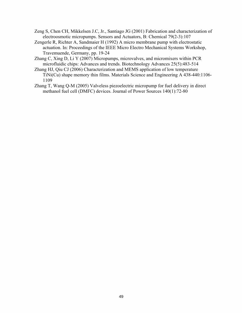
49
Zeng S, Chen CH, Mikkelsen J.C, Jr., Santiago JG (2001) Fabrication and characterization of electroosmotic micropumps. Sensors and Actuators, B: Chemical 79(2-3):107
Zengerle R, Richter A, Sandmaier H (1992) A micro membrane pump with electrostatic actuation. In: Proceedings of the IEEE Micro Electro Mechanical Systems Workshop, Travemuende, Germany, pp. 19-24
Zhang C, Xing D, Li Y (2007) Micropumps, microvalves, and micromixers within PCR microfluidic chips: Advances and trends. Biotechnology Advances 25(5):483-514
Zhang HJ, Qiu CJ (2006) Characterization and MEMS application of low temperature TiNi(Cu) shape memory thin films. Materials Science and Engineering A 438-440:1106-1109
Zhang T, Wang Q-M (2005) Valveless piezoelectric micropump for fuel delivery in direct methanol fuel cell (DMFC) devices. Journal of Power Sources 140(1):72-80

50
Table I. Young’s Modulus and coefficient of thermal expansion (CTE) for common micropump materials.
Material Young’s Modulus [GPa] Linear Coefficient of Thermal Expansion (CTE) [ppm/°C]
Aluminum 47-74 (MEMSnet 2007) 25 (Kovacs 1998)
Glass 40-80 (MEMSnet 2007) 0.1-3 (Chen et al. 2000)
Gold 80 (MEMSnet 2007) 14.2 (Kovacs 1998)
Parylene 2-3 (SCS Coatings 2007) 35-80 (SCS Coatings 2007)
PDMS 0.36-0.87 (Armani et al. 1999) 270-310 (Grzybowski et al. 1999)
Platinum 170 (MEMSnet 2007) 8.8 (Kovacs 1998)
Polyimide 3-15 (MEMSnet 2007) 3-191 (Kovacs 1998)
Silicon 125-202 (MEMSnet 2007) 2.6 (Kovacs 1998)
Silicon Dioxide 46-92 (MEMSnet 2007) 0.35-0.4 (Kovacs 1998)
Silicon Nitride 100-325 (MEMSnet 2007) 1.6 (Kovacs 1998)
Silicone Rubber 0.0062 (SCS Coatings 2007) 250-300 (SCS Coatings 2007)
Silver 76 (MatWeb 2007) 18.9 (Kovacs 1998)
Stainless Steel 200-240 (MEMSnet 2007) 10-20 (Ilavsky and Berndt 1998)

51
Table II. Quantitative comparison of various micropumps in the recent literature. A similar comparison for literature prior to 2005 is available in Singhal et al. (2004).
Size
Micropumping Technique
Actuation Method
Qmax [μl/min], Qmax/Ap
[μl/min.mm2]
pback,
max [kPa]
V [V], V/Q [V.min/ml]
P [W], P/Q [W.min/ml]
Planform, Outlet Areas
[mm × mm]
Out of Plane [mm]
ν Reference
Mechanical Displacement Pumps
Vibrating Diaphragm PVDF 106 (air), 55.5 -
106 (V/μm), 1000
(V.min/ml.μm)
- dia 1.56, dia 1.56† 0.4 100
Hz (Xu and Su
2005)
Vibrating Diaphragm Electrostatic 1 (DI water),
0.04 - 50, 50000 - 5 x 5,
0.078 x 0.078
0.063 1.83 kHz
(Machauf et al. 2005)
Magnetic, DC motor
774 (water), 12.9
1.7 (6.2 Hz)
0.013, 0.017
5.9 Hz Vibrating
Diaphragm Magnetic, coil 1000 (water),
16.7
7.5 (4
Hz)
-
0.5, 0.5
10 x 6†, dia 1.2 2†
5 Hz
(Pan et al. 2005)
Vibrating Diaphragm
Magnetic, ball valves
5000 (water), 63.7 28 - - dia 10,
1 x 0.4 2.5 30 Hz
(Yamahata et al. 2005b)
Vibrating Diaphragm
Thermo-pneumatic
0.078 (methanol),
0.034 - 55,
705128 - 6.5 x 3.5, dia 1 1 6 Hz (Kim et al.
2005a)
Vibrating Diaphragm Piezoelectric
32900 (methanol),
1446
0.173 150, 4.56 -
6.5 x 3.5, 0.08 x 0.35†
0.08 300 Hz
(Kim et al. 2005b)
Vibrating Diaphragm
Electro-magnetic
400 (water), 6.29 1.3 - - dia 9,
0.25 x 0.5 0.5 12 Hz
(Yamahata et al. 2005c)
Vibrating Diaphragm Piezoelectric 3.2 (water),
0.135 0.12 80, 25000 0.003, 0.938
dia 5.5, 0.15 x 0.15 1.6 60
kHz (Feng and Kim 2005)
Vibrating Diaphragm
Piezoelectric with throttles 750 (water), 50 18 140 (pp),
187 - 15† x 1, 1 x 0.1 0.1 1.6
kHz (Tracey et al.
2006) Vibrating
Diaphragm Piezoelectric 1800 (water), 5.45 60 250†, 139 0.084†,
0.047 30 x 11,
0.4 x 0.4† 1 27.8 Hz
(Doll et al. 2006)
Vibrating Diaphragm Piezoelectric 1300 (water),
5.46 4.1 400 (pp), 308 - 17 x 14,
0.12 x 0.12 0.12 200 Hz
(Nguyen et al. 2006)
Vibrating Diaphragm
Solid-liquid phase change
0.074 (water), 0.001 920 - - 12 x 6,
dia 0.6 2 0.5 Hz
(Boden et al. 2006)
Vibrating Diaphragm Electrostatic 0.18 (air),
0.045 7 100 (pp), 555555 - 2 x 2,
2 x 2 0.1 14 kHz
(Astle et al. 2007)
Vibrating Diaphragm Piezoelectric 323 (water),
3.23 0.29 385, 1192 - 10 x 10 1 x 0.2 0.2 130
Hz (Yoon et al.
2007) Vibrating
Diaphragm Pneumatic 2600 (water), 192.6 25 - - 1.5 x 9,
0.4 x 0.4 0.19 50 Hz
(Inman et al. 2007)
Peristaltic Pneumatic 7.5 (water and glycerol), 0.87 - - -
20 x 0.431, 0.431 x 0.045
0.045 250 Hz
(Goulpeau et al. 2005)
Peristaltic Thermo-pneumatic
21.6 (water), 1.08 3.5 20, 925.9 - 8 x 2.5,
0.1 x 0.047 550 2 Hz (Jeong et al. 2005)
Peristaltic 13 (water), 2.14 172 - - 3.6 x 14,
0.5 x 0.1 0.1 10 Hz
(Huang et al. 2006a)
Peristaltic Magnetic Fluid 3.8, 0.06 9 x 9, 3 x 0.3 0.3 (Kim et al.
2006)
Peristaltic Piezoelectric 36.8 (water), 0.02 0.52 100, 2717 0.4, 10.9 75 x 24,
1† x 0.2 1.1 700 Hz
(Jang et al. 2007)
Peristaltic (Back pressure Independent)
Piezoelectric 30 (water), 0.23 30 80, 2667 - 8 x 16,
dia 0.8 - 4 Hz (Geipel et al. 2007)
Fluid Displacement Magnetic Fluid 30 (water), 0.3 2.5 - - 7 x 14
1 x 1† 6 0.2†
Hz (Yamahata et
al. 2005a)
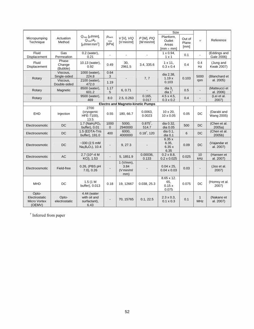
52
Size
Micropumping Technique
Actuation Method
Qmax [μl/min], Qmax/Ap
[μl/min.mm2]
pback,
max [kPa]
V [V], V/Q [V.min/ml]
P [W], P/Q [W.min/ml]
Planform, Outlet Areas
[mm × mm]
Out of Plane [mm]
ν Reference
Fluid Displacement
Gas Permeation
0.2 (water), 0.21 - - - 1 x 0.94,
1 x 1 0.1 - (Eddings and Gale 2006)
Fluid Displacement
Phase Change (Bubble)
10.13 (water), 0.92 0.49 30,
2961.5 3.4, 335.6 1 x 11, 0.3 x 0.4 0.4 0.4
Hz (Jung and
Kwak 2007)
Viscous, Single-sided
1000 (water), 224.8
0.643 Rotary Viscous,
Double-sided 2100 (water),
472.0 1.19 - 7, 7
dia 2.38, 1.19 x 0.103
0.103 5000 rpm
(Blanchard et al. 2005)
Rotary Magnetic 8500 (water), 601.2
1.175 6, 0.71 - dia 3,
dia 1† 0.5 - (Matteucci et al. 2006)
Rotary 9500 (water), 469 8.0 2.5, 0.263 0.165,
0.017 4.5 x 4.5, 0.3 x 0.2 0.4 - (Lei et al.
2007) Electro and Magneto-kinetic Pumps
EHD Injection
2700 (cryogenic HFE-7100),
13.5
0.55 180, 66.7 0.0063, 0.0023
10 x 20, 10 x 0.05 0.05 DC (Darabi and
Wang 2005)
Electroosmotic DC 1.7 (NaH2PO4 buffer), 0.01
10000
5000, 2940000
0.875†, 514.7
dia 0.32, dia 0.05 500 DC (Chen et al.
2005a)
Electroosmotic DC 1.5 (EDTA-Tris buffer), 191.0 400 6000,
4000000 0.18†, 120 dia 0.1, dia 0.1 6 DC (Chen et al.
2005b)
Electroosmotic DC ~330 (2.5 mM Na2B4O7), 10.4 - 9, 27.3 -
6.35 x 6.35,
6.35 x 6.35
0.09 DC (Vajandar et al. 2007)
Electroosmotic AC 2.7 (10^-4 M KCl), 1.53 - 5, 1851.9 0.00036,
0.133 0.2 x 8.8,
0.2 x 0.025 0.025 10 kHz
(Hansen et al. 2007)
Electroosmotic Field-free 0.26, (PBS pH 7.0), 0.26 -
1 (V/mm), 3.84
(V.min/ml.mm)
- 0.04 x 25, 0.04 x 0.03 0.03 - (Joo et al.
2007)
MHD DC 1.5 (1 M buffer), 0.013 0.18 19, 12667 0.038, 25.3
8.65 x 12. 65,
0.15 x 0.075
0.075 DC (Homsy et al. 2007)
Opto-Electrostatic Micro Vortex
(OEMV)
Opto-electrostatic
4.44 (water with oil and surfactant),
6.43
- 70, 15765 0.1, 22.5 2.3 x 0.3, 0.1 x 0.3 0.1 1
MHz (Nakano et al. 2007)
† Inferred from paper

53
Mechanical Displacement(Moving boundary or liquid displacement pressure force, sect. 2)
Electro- and Magneto-kinetic(Continuous, direct energy transfer, sect. 3)
Fluid(sect. 2.2)
Piezoelectric
Electrostatic
Electromagnetic/ Magnetic
Thermal
Pneumatic
Composite / Polymer Materials
Diaphragm(sect. 2.1)
Ferrofluid
Phase Change
Gas Boundary
Rotary (sect. 2.3)
Rotating Gear
Viscous Force
Electrohydrodynamic(sect. 3.1)
Magnetohydrodynamic(sect. 3.3)
OptoelectrostaticMicrovortex
Induction
Flexural Plate Wave
Irreversible
Peristaltic
Electroosmotic(sect. 3.2)
Electrowetting(sect. 3.4)
Other(sect. 3.5)
Injection
Polarization
Ion Drag
DC
AC
Valves
Figure 1. Categorization of pumping mechanisms (topics are discussed in the order presented here).
54
Diaphragm
Inlet valve Outlet valve
(a)
(b)
(c)
Figure 2. Vibrating diaphragm micropump in an (a) undeflected position, and during an (b) expansion and (c) contraction stroke.

55
Diaphragms
Sequential pumping chambers
Figure 3. Structure and operation of a peristaltic micropump.

56
Expansion stroke
Compression stroke
Figure 4. Dynamic, active diaphragm valves.

57
Inlet choke Outlet choke
Diaphragm actuator
Resistance heaters (viscosity control)
Diffuser action
Expansion stroke
Diffuser actionNozzle action
Compression strokeNozzle action
Outlet Inlet
(a)
(b)
Diaphragm actuator
Inlet Outlet
Reverse operation
Inlet
Outlet
Forward operation
Net flow from left to right
Reverse operation
Inlet
Outlet
Forward operation
Net flow from left to right
(c)
(d)
Figure 5. Static, fixed-geometry valves: (a) thermally-controlled viscosity valve, (b-c) nozzle-diffuser valves and (d) Tesla valve.

58
Bubble Heater array
Bubble expansion
Bubble translation
Figure 6. Bubble micropump with sequential bubble growth stages.
Electrodes
Bubbles
Figure 7. Electrochemical micropump schematic.

59
Rotating blades Rotating cylinder
Static microchannel
(a) (b)
Spiral channel
(substrate)
Rotating coverplate
Rotating disk (boundary)
Static microchannel inlet/outlet
(c) (d)
Figure 8. Principle of operation of (a) rotating blade, and (b) eccentric viscous, (c) spiral-channel viscous, and (d) disk viscous micropumps.

60
Heat Flux
Increasing Electrical
Conductivity
Temperature Gradient
Sinusoidal Potential
Velocity Profile
_ + _ _+ +
Emitter electrodes Collector electrodes
(a)
(b)
Electrodes
V
(c)
Figure 9. EHD micropumps with (a) traveling-wave, induction-type, (b) planar injection-type, and (c) polarization-type driving mechanisms.

61
+ _
+ + + + + + + + +_ _ _ _ _ _ _ _ _ _ _
++
++
++ +
+ ++
++_
_ _
_ +
_ +
_ ++ _
Stern layer (immobile)Diffuse layer (mobile)
Figure 10. DC electroosmotic micropump and corresponding flow profile.
Net velocity field
Electrodes
Electrolyte
Figure 11. AC electroosmotic flow and corresponding flow profile.
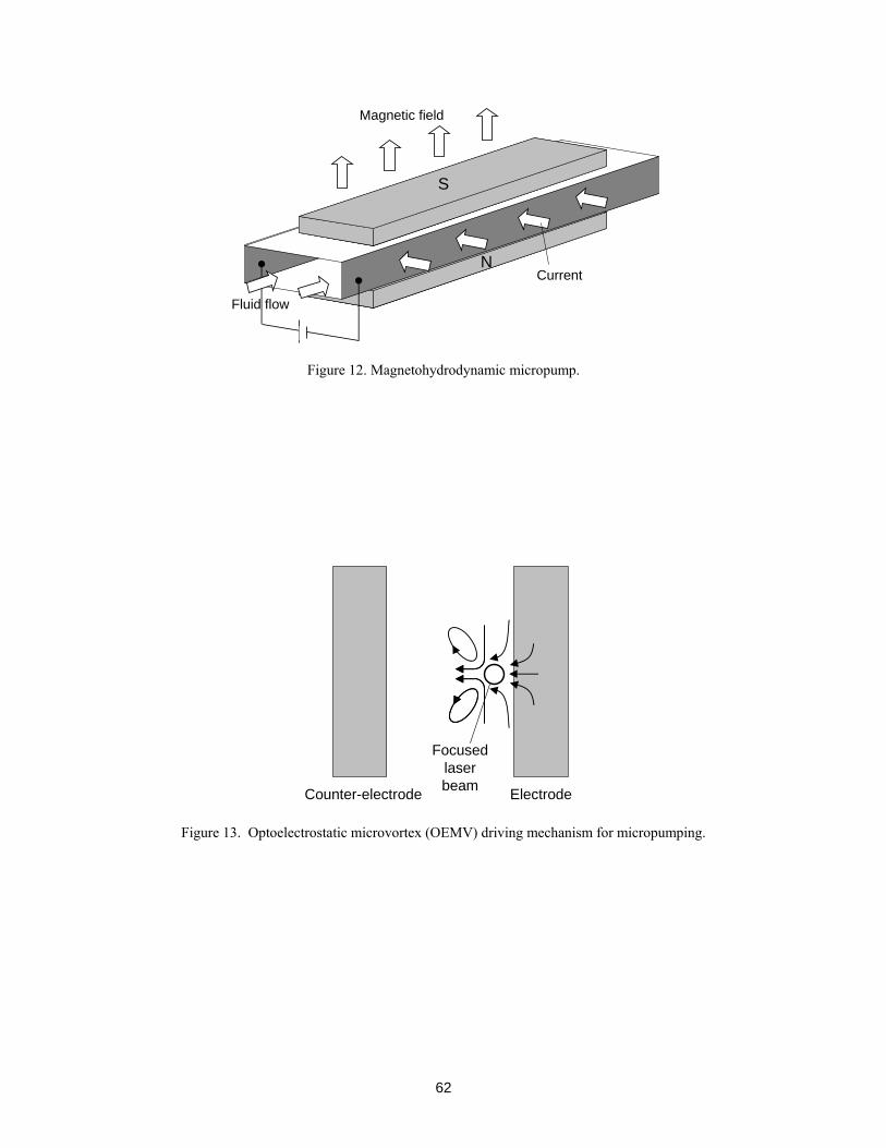
62
N
S
Magnetic field
Fluid flow
Current
Figure 12. Magnetohydrodynamic micropump.
ElectrodeCounter-electrode
Focused laser beam
Figure 13. Optoelectrostatic microvortex (OEMV) driving mechanism for micropumping.

63
Induced acoustic
streaming
Flexural plate waveInterdigitated piezoelectric transducers
Figure 14. Flexural plate wave micropump.

64
(a)
(b)

65
(c)
Figure 15. Reported (a) maximum back pressure, (b) maximum flow rate per unit planform area and (c) maximum flow rate per unit outlet area for pumps included in Table II.