Receiver testing for PHYs based on...
24
Receiver testing for PHYs based on 10GBASE-KR IEEE P802.3ba Task Force Meeting Dallas, TX November 2008 Adam Healey LSI Corporation Richard Mellitz Intel John D’Ambrosia Force10 Networks
Transcript of Receiver testing for PHYs based on...
Receiver testing for PHYs based on 10GBASE-KR
IEEE P802.3ba Task Force MeetingDallas, TX
November 2008
Adam HealeyLSI Corporation
Richard MellitzIntel
John D’AmbrosiaForce10 Networks

2Healey 11/4/2008 IEEE P802.3ba Task Force
Motivation
• Clauses 84 and 85 define multi-lane PMD sub-layers that seek to have commonality with Clause 72 (10GBASE-KR)
• In IEEE P802.3ba/Draft 1.0, both Clauses 84 and 85 reference Clause 72 receiver requirements, including the receiver interference tolerance test (72.7.2.1)
• The test methodology is defined in Annex 69A and applies to a single 10GBASE-KR receiver tested in isolation
• It is unclear how this methodology should be applied to the multi-lane PMD sub-layers in question
• Concepts may apply to XLAUI, CAUI, and PPI but these interfaces are not considered in this presentation

3Healey 11/4/2008 IEEE P802.3ba Task Force
Citations
• 84.8.2.1 Receiver interference tolerance– The receiver interference tolerance tests are the same as those described
for 10GBASE-KR in 72.7.2.1 and Annex 69A.
• 85.8.4 Receiver characteristics– Receiver characteristics are summarized in Table 85–5 and as detailed in
72.7.2.1 through 72.7.2.5 with the exception of the receiver characteristics specified in 85.8.4.1, 85.8.4.2, and 85.8.4.3.
• 85.8.4.1 Bit error ratio– The receiver shall operate with a BER 10–12 or better when receiving a
compliant transmit signal, as defined in 85.8.3, through a compliant cable assembly as defined in 85.9 exhibiting the maximum insertion loss of 85.9.2.

4Healey 11/4/2008 IEEE P802.3ba Task Force
Topics
• Multi-lane PMD sub-layer observations
• Review of 10GBASE-KR interference tolerance
• Applicability to Clauses 84 and 85
• Additional crosstalk considerations

Multi-lane PMD sub-layer observations

6Healey 11/4/2008 IEEE P802.3ba Task Force
Illustration of the sources of coupled noise
Alien FEXT (AFEXT)
Alien NEXT (ANEXT)
FEXT
NEXT
fa
fc
fd
fbDevice package Mated connector

7Healey 11/4/2008 IEEE P802.3ba Task Force
Crosstalk assumptions
• Aggressors are not correlated to the victim or each other and crosstalk combines in terms of a power sum
• Aggressors are not synchronous to the victim or each other• FEXT aggressor and victim transmitter characteristics, such as output
voltage and transition time, match within some constraint• NEXT aggressors all exhibit worst-case characteristics• ANEXT and AFEXT aggressors, when present, also exhibit worst-case
characteristics• Alien crosstalk is not significant for a shielded copper cable assembly

Review of 10GBASE-KR interference tolerance

9Healey 11/4/2008 IEEE P802.3ba Task Force
10GBASE-KR interference tolerance test setup
Compliant transmitter, but at specification limits
Channel attenuation within recommendations
Channel noise at limit of ICR recommendations
Source: IEEE 802.3apTM-2007, Annex 69A
Adaptation loop may be closed prior to the test

10Healey 11/4/2008 IEEE P802.3ba Task Force
General assumptions
• Test channel insertion loss is ILTC (f)• Test channel return loss is better than 20 dB• PSXT(f) = ICRmin (f) + ILTC (f)• Worst-case attenuation and noise within channel recommendations• 3 dB margin required for reflective losses not included in test channel• Two test cases are defined to ensure the implementation can tolerate
reasonable mixtures of loss and noise permitted by the ICRmin (f)

11Healey 11/4/2008 IEEE P802.3ba Task Force
Transmitter assumptions
• Peak-to-peak differential output voltage is the smallest compliant value• Transition time is the largest compliant value• Duty cycle distortion (DCD) is the largest compliant value• Deterministic jitter (DJ) is the largest compliant value less DCD and is
modeled as sinusoidal jitter (SJ) at no less than 1/250 of the signaling speed
• Random jitter (RJ) is the largest compliant total jitter (TJ) less SJ and DCD

12Healey 11/4/2008 IEEE P802.3ba Task Force
Noise assumptions
• All crosstalk aggressors are considered alien• All aggressors are compliant to the 10GBASE-KR standard• Aggressors are not synchronous or correlated to the victim• Aggressor peak-to-peak differential output voltage is the largest
compliant value• Aggressor transition time is the smallest compliant value• Crest factor (peak-to-RMS ratio) does not exceed 5

13Healey 11/4/2008 IEEE P802.3ba Task Force
10GBASE-KR noise equations
Equation Description
Gaussian filter with 20 to 80% transition time, Tr
Aggressor input power spectral density (PSD) with peak differential output voltage Vpk and unit interval T
Power sum crosstalk loss
Aggressor output PSD
Aggressor output variance
Amplitude of broadband noise (RMS)
⎟⎟⎠
⎞⎜⎜⎝
⎛⎟⎠⎞
⎜⎝⎛−=
2
6832.12
21exp)( rTffH π
222 )()(sinc)( fHTfTVfS pki =
)()()( fILfICRfPSXT TCmin +=
10)(10)()( fPSXTia fSfS −=
∫=maxf
aa dffS0
2 )(2σ
2010Man σσ =

14Healey 11/4/2008 IEEE P802.3ba Task Force
10GBASE-KR noise calculations
Parameter Test 1 value Test 2 value Units
Test channel insertion loss, ILTC (f) Amax (f) Amax (f)/2 dBAggressor transition time 24 24 psAggressor peak differential output voltage 600 600 mVMargin for reflective loss 3 3 dBAmplitude of broadband noise (RMS) 5.2 11.6 mV

Applicability to Clauses 84 and 85

16Healey 11/4/2008 IEEE P802.3ba Task Force
Approaches to receiver specification – 1
• Specify that the receiver shall operate at the target BER or better when connected to a compliant transmitter using a compliant channel– Convenient from the perspective of writing a specification– To ensure interoperability, the worst case must be examined as a member
of the set of compliant transmitters and channels– Emulation of worst-case operating conditions is an exercise left to the user
of the standard– Leads to inconsistency in verification methods, and therefore results
17Healey 11/4/2008 IEEE P802.3ba Task Force
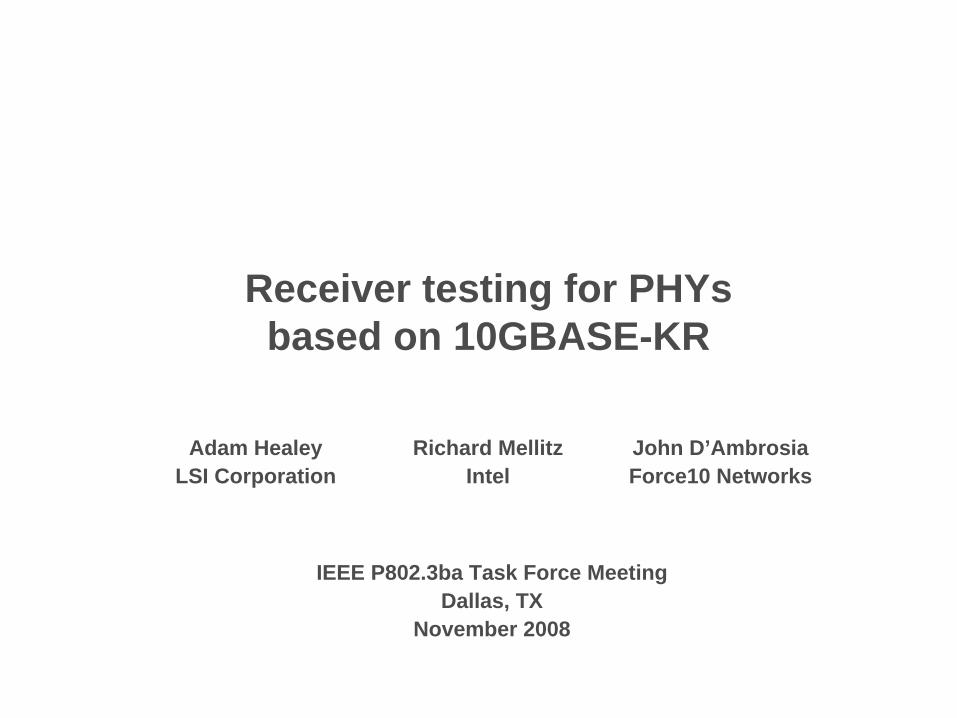
Approaches to receiver specification – 2
• Test each individual lane in isolation using the methodology defined in Annex 69A– Plus, define the state of unused lanes (e.g. terminated, transmitters active)– Captures impact of host and package NEXT, but not FEXT– Will not capture any interaction between the lanes resulting from the parallel
operation of transmitter control loops– Reliant on PMA-based test pattern generators and checkers
Frequency-dependent attenuator
Interference generator
Interference injection
Pattern generator
Transmitter control
fb
T
TT
T
TT
T
TP3 (Clause 85)
TP4 (Clause 84)
18Healey 11/4/2008 IEEE P802.3ba Task Force
Approaches to receiver specification – 3
• Define a test set-up that emulates the worst-case multi-lane transmitter and channel
• Could be an N-fold replication of the test set-up defined in Annex 69A– Burdensome N-fold replication of test equipment– Additional test coverage limited to host and package FEXT
• N instances of test channel and interference generator may be avoided if a new multi-lane test channel could be designed with the worst-case insertion loss on each lane and worst-case crosstalk coupling between lanes– It is not clear that this even feasible– If feasible, then the concern shifts to availability from a broad set of suppliers– There is still the need to emulate a worst-case transmitter– It is not clear how to guarantee margin for reflective losses or alien crosstalk
19Healey 11/4/2008 IEEE P802.3ba Task Force
Additional considerations for Clause 85
• If the transmitter requirements apply at TP2, must loosen requirements to account for Tx_PCB, mated connector, and test fixture insertion loss between TP1 and TP2– Adjust emulation of worst-case transmitter accordingly
• If the receiver requirements apply at TP3, the test channel should be based on the cable assembly attenuation and not channel attenuation– Do not double count Rx_PCB insertion loss– Perhaps remove the insertion loss of one mated connector as well– Define new ILTC (f) equation(s) for Clause 85
• Adjust ICRmin (f) for the TP2 to TP3 span
• Broadband noise amplitude may then be calculated using 10GBASE- KR formulae

Additional crosstalk considerations

21Healey 11/4/2008 IEEE P802.3ba Task Force
Treatment of FEXT for the multi-lane case
• If individual limits were applied to the various crosstalk components…
• …and matching requirements were imposed on the transmitters in the N-lane interface…
• …some degree of pessimism could be removed from the broadband noise calculation
• Consider the example where the power-sum FEXT loss is 10log10 (a) dB down from the power-sum crosstalk loss, PSXT(f)

22Healey 11/4/2008 IEEE P802.3ba Task Force
Revised noise analysis
Equation Description
Gaussian filter with 20 to 80% transition time, Tm
Aggressor input power spectral density (PSD) with peak differential output voltage Vm and unit interval T
Far-end crosstalk loss
Composite aggressor input PSD
Effective aggressor output PSD
⎟⎟⎠
⎞⎜⎜⎝
⎛⎟⎠⎞
⎜⎝⎛−=
2
6832.12
21exp)( r
mTffH π
222 )()(sinc)( fHTfTVfS mmm =
)(log10)()( 10 afPSXTfPSFEXT −=
)()()1()( fSafSafS mic +−=
10)(10)()( fPSXTca fSfS −=

23Healey 11/4/2008 IEEE P802.3ba Task Force
Calculation example
Parameter Test 1 value Test 2 value Units
Test channel insertion loss, ILTC (f) Amax (f) Amax (f)/2 dB10 log10 (a) 6 6 dBFEXT aggressor transition time1 41 41 psFEXT aggressor peak differential output voltage1 460 460 mVAggressor transition time 24 24 psAggressor peak differential output voltage 600 600 mVMargin for reflective loss 3 3 dBAmplitude of broadband noise (RMS) 4.9 10.8 mV1 Assume approximately 15% spread in transmitter characteristics across the N lanes

24Healey 11/4/2008 IEEE P802.3ba Task Force
Recommendations
• Test each individual lane in isolation using the methodology defined in Annex 69A– Plus, define the state of unused lanes (e.g. terminated, transmitters active)
• Adjust transmitter, ILTC (f), and ICRmin (f) parameters in Clause 85 to account for the specification of receiver parameters at TP3
• Consider separate limits for PSNEXT and alien crosstalk (if applicable) in addition to ICR– PSFEXT contribution may be derived from these parameters
• Consider matching requirements for the multi-lane transmitter
• Recalculate equivalent broadband noise for the interference tolerance test considering the new requirements