Recall: Liang Barsky 3D Clipping
44
Recall: Liang‐Barsky 3D Clipping Goal: Clip object edge-by-edge against Canonical View volume (CVV) Problem: 2 end-points of edge: A = (Ax, Ay, Az, Aw) and C = (Cx, Cy, Cz, Cw) If edge intersects with CVV, compute intersection point I =(Ix,Iy,Iz,Iw)
Transcript of Recall: Liang Barsky 3D Clipping

Recall: Liang‐Barsky 3D Clipping
Goal: Clip object edge-by-edge against Canonical View volume (CVV)
Problem: 2 end-points of edge: A = (Ax, Ay, Az, Aw) and C = (Cx, Cy, Cz, Cw) If edge intersects with CVV, compute intersection point I =(Ix,Iy,Iz,Iw)
Recall: Determining if point is inside CVV
x = -1 x = 1
Problem: Determine if point (x,y,z) is inside or outside CVV?
Point (x,y,z) is inside CVV if(-1 <= x <= 1)
and (-1 <= y <= 1)and (-1 <= z <= 1)
else point is outside CVV
CVV == 6 infinite planes (x=‐1,1; y=‐1,1; z=‐1,1)
y= -1
y = 1

Recall: Determining if point is inside CVV
If point specified as (x,y,z,w) - Test (x/w, y/w , z/w)!
Point (x/w, y/w, z/w) is inside CVV
if (-1 <= x/w <= 1) and (-1 <= y/w <= 1)
and (-1 <= z/w <= 1)
else point is outside CVV
x /w = 1
y/w = -1
y/w = 1
x/w = -1

Recall: Modify Inside/Outside Tests Slightly
Our test: (-1 < x/w < 1)
Point (x,y,z,w) inside plane x = 1 if
x/w < 1 => w – x > 0
Point (x,y,z,w) inside plane x = -1 if
-1 < x/w => w + x > 0
x /w = 1
y/w = -1
y/w = 1
x/w = -1

Recall: Numerical Example: Inside/Outside CVV Test
Point (x,y,z,w) is inside plane x=-1 if w+x > 0 inside plane x=1 if w – x > 0
Example Point (0.5, 0.2, 0.7) inside planes (x = -1,1) because - 1 <= 0.5 <= 1
If w = 10, (0.5, 0.2, 0.7) = (5, 2, 7, 10) Can either divide by w then test: – 1 <= 5/10 <= 1 OR
To test if inside x = - 1, w + x = 10 + 5 = 15 > 0 To test if inside x = 1, w - x = 10 - 5 = 5 > 0
-1 1
x/w

Recall: 3D Clipping
Do same for y, z to form boundary coordinates for 6 planes as:
Boundary coordinate (BC)
Homogenous coordinate
Clip plane Example(5,2,7,10)
BC0 w+x x=-1 15
BC1 w-x x=1 5
BC2 w+y y=-1 12
BC3 w-y y=1 8
BC4 w+z z=-1 17BC5 w-z z=1 3
Consider line that goes from point A to C
Trivial accept: 12 BCs (6 for pt. A, 6 for pt. C) > 0
Trivial reject: Both endpoints outside (-ve) for same plane

Edges as Parametric Equations
Implicit form
Parametric forms: points specified based on single parameter value Typical parameter: time t
Some algorithms work in parametric form Clipping: exclude line segment ranges Animation: Interpolate between endpoints by varying t
Represent each edge parametrically as A + (C – A)t at time t=0, point at A at time t=1, point at C
0),( yxF
tPPPtP *)()( 010 10 t

Inside/outside? Test A, C against 6 walls (x=-1,1; y=-1,1; z=-1,1)
There is an intersection if BCs have opposite signs. i.e. if either A is outside (< 0), C is inside ( > 0) or
A inside (> 0) , C outside (< 0)
Edge intersects with plane at some t_hit between [0,1]
A
Ct_hit
C
A t_hit
t = 0
t = 1 t = 0
t = 1

Calculating hit time (t_hit)
How to calculate t_hit?
Represent an edge t as:
E.g. If x = 1,
Solving for t above,
1)(
)(
tAwCwAwtAxCxAx
)()( CxCwAxAwAxAwt
))((,)((,)((,)((()( tAwCwAwtAzCzAztAyCyAytAxCxAxtEdge

Inside/outside? t_hit can be “entering (t_in) ” or ”leaving (t_out)”
Define: “entering” if A outside, C inside
Why? As t goes [0‐1], edge goes from outside (at A) to inside (at C)
Define “leaving” if A inside, C outside Why? As t goes [0-1], edge goes from inside (at A) to inside (at C)
A
Ct_in
C
At_out
Entering
t = 0
t = 1 t = 0
t = 1
Leaving
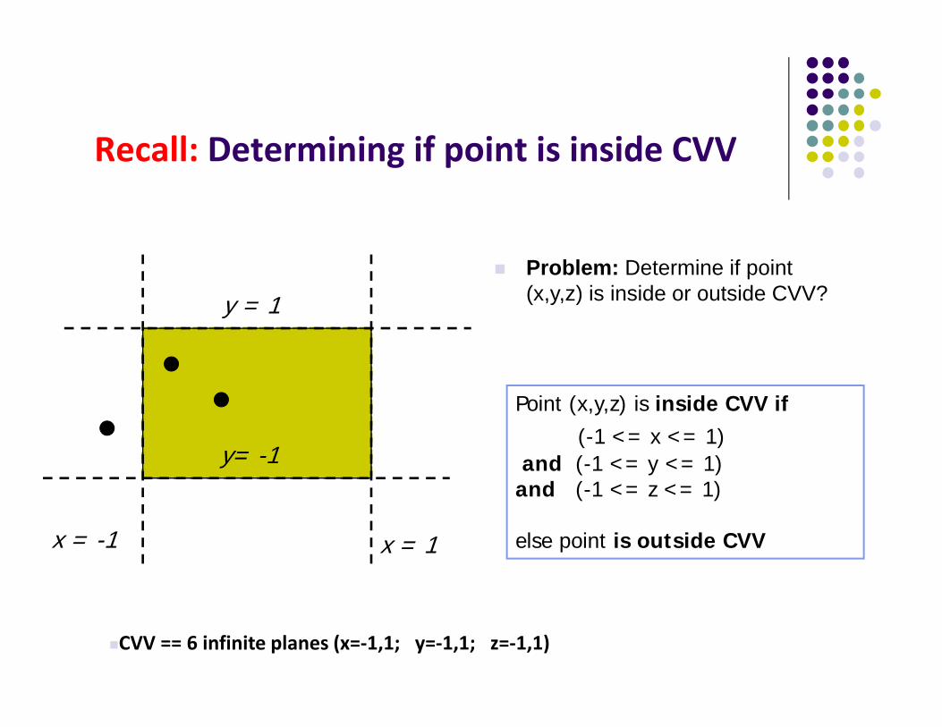
Chop step by Step against 6 planes Initially
Chop against each of 6 planes
A
C
t = 0
t = 1
t_in = 0, t_out = 1Candidate Interval (CI) = [0 to 1]
A
C
t = 0
t_out = 0.74 Plane y = 1
t_in = 0, t_out = 0.74Candidate Interval (CI) = [0 to 0.74] Why t_out?

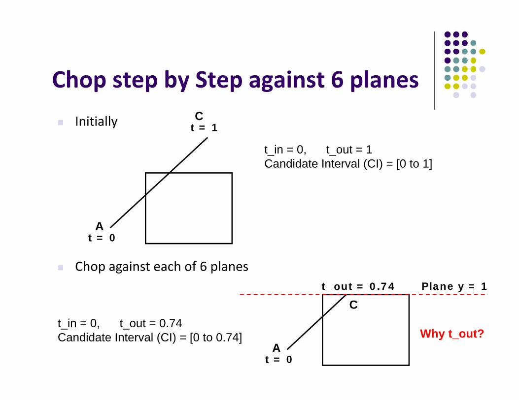
Chop step by Step against 6 planes Initially
Then
A
C
t = 0
t_out = 0.74
t_in = 0, t_out = 0.74Candidate Interval (CI) = [0 to 0.74]
A
Ct_out = 0.74
t_in = 0.36, t_out = 0.74Candidate Interval (CI) CI = [0.36 to 0.74]
t_in= 0.36
Why t_in?
Plane x = -1

Candidate Interval
Candidate Interval (CI): time interval during which edge might still be inside CVV. i.e. CI = t_in to t_out
Initialize CI to [0,1]
For each of 6 planes, calculate t_in or t_out, shrink CI
Conversely: values of t outside CI = edge is outside CVV
0 1
tt_in t_out
CI

Shortening Candidate Interval
Algorithm: Test for trivial accept/reject (stop if either occurs)
Set CI to [0,1]
For each of 6 planes:
Find hit time t_hit
If t_in, new t_in = max(t_in,t_hit)
If t_out, new t_out = min(t_out, t_hit)
If t_in > t_out => exit (no valid intersections)
Note: seeking smallest valid CI without t_in crossing t_out0 1
tt_in t_out
CI

Calculate choppped A and C
If valid t_in, t_out, calculate adjusted edge endpoints A, C as
A_chop = A + t_in ( C – A) (calculate for Ax,Ay, Az) C_chop = A + t_out ( C – A) (calculate for Cx,Cy,Cz)
0 1
tt_in t_out
CIA_chop C_chop

3D Clipping Implementation
Function clipEdge( ) Input: two points A and C (in homogenous coordinates) Output: 0, if AC lies complete outside CVV 1, complete inside CVV Returns clipped A and C otherwise
Calculate 6 BCs for A, 6 for C
ClipEdge ()0
1A_chop, C_chop
A
C

Store BCs as Outcodes
Use outcodes to track in/out Number walls x = +1, ‐1; y = +1, ‐1, and z = +1, ‐1 as 0 to 5 Bit i of A’s outcode = 1 if A is outside ith wall 1 otherwise
Example: outcode for point outside walls 1, 2, 5
0 1 2 3 4 50 1 1 0 0 1
Wall no.OutCode
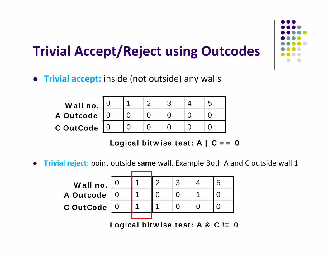
Trivial Accept/Reject using Outcodes
Trivial accept: inside (not outside) any walls
Trivial reject: point outside same wall. Example Both A and C outside wall 1
0 1 2 3 4 50 0 0 0 0 00 0 0 0 0 0
Wall no.A OutcodeC OutCode
0 1 2 3 4 50 1 0 0 1 00 1 1 0 0 0
Wall no.A OutcodeC OutCode
Logical bitwise test: A | C == 0
Logical bitwise test: A & C != 0

3D Clipping Implementation
Compute BCs for A,C store as outcodes Test A, C outcodes for trivial accept, trivial reject If not trivial accept/reject, for each wall: Compute tHit Update t_in, t_out If t_in > t_out, early exit

3D Clipping Pseudocodeint clipEdge(Point4& A, Point4& C){
double tIn = 0.0, tOut = 1.0, tHit;double aBC[6], cBC[6];int aOutcode = 0, cOutcode = 0;
…..find BCs for A and C…..form outcodes for A and C
if((aOutCode & cOutcode) != 0) // trivial rejectreturn 0;
if((aOutCode | cOutcode) == 0) // trivial acceptreturn 1;

3D Clipping Pseudocode
for(i=0;i<6;i++) // clip against each plane{
if(cBC[i] < 0) // C is outside wall i (exit so tOut){
tHit = aBC[i]/(aBC[i] – cBC[I]); // calculate tHittOut = MIN(tOut, tHit);
}else if(aBC[i] < 0) // A is outside wall I (enters so tIn){
tHit = aBC[i]/(aBC[i] – cBC[i]); // calculate tHittIn = MAX(tIn, tHit);
}if(tIn > tOut) return 0; // CI is empty: early out
}
)()( CxCwAxAwAxAwt

3D Clipping PseudocodePoint4 tmp; // stores homogeneous coordinatesIf(aOutcode != 0) // A is outside: tIn has changed. Calculate A_chop{
tmp.x = A.x + tIn * (C.x – A.x);// do same for y, z, and w components
}If(cOutcode != 0) // C is outside: tOut has changed. Calculate C_chop{
C.x = A.x + tOut * (C.x – A.x);// do same for y, z and w components
}A = tmp; Return 1; // some of the edges lie inside CVV}
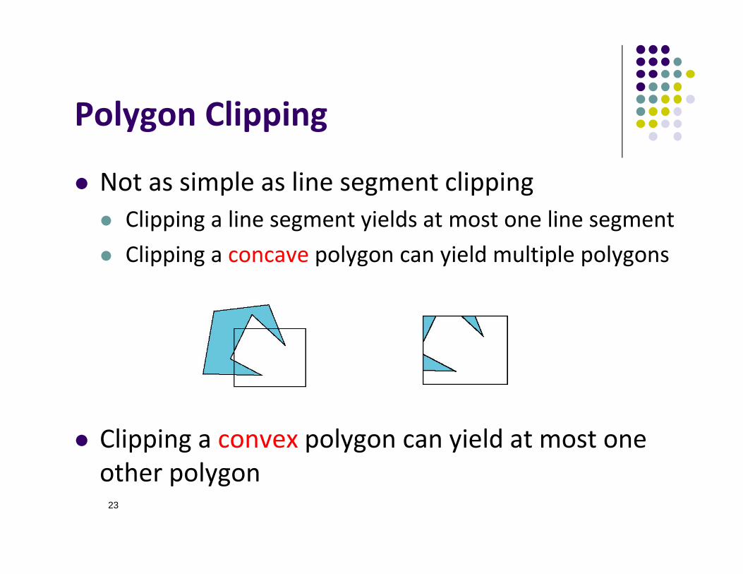
Polygon Clipping
Not as simple as line segment clipping Clipping a line segment yields at most one line segment Clipping a concave polygon can yield multiple polygons
Clipping a convex polygon can yield at most one other polygon
23

Clipping Polygons
Need more sophisticated algorithms to handle polygons: Sutherland‐Hodgman: clip any given polygon against a
convex clip polygon (or window) Weiler‐Atherton: Both clipped polygon and clip
polygon (or window) can be concave
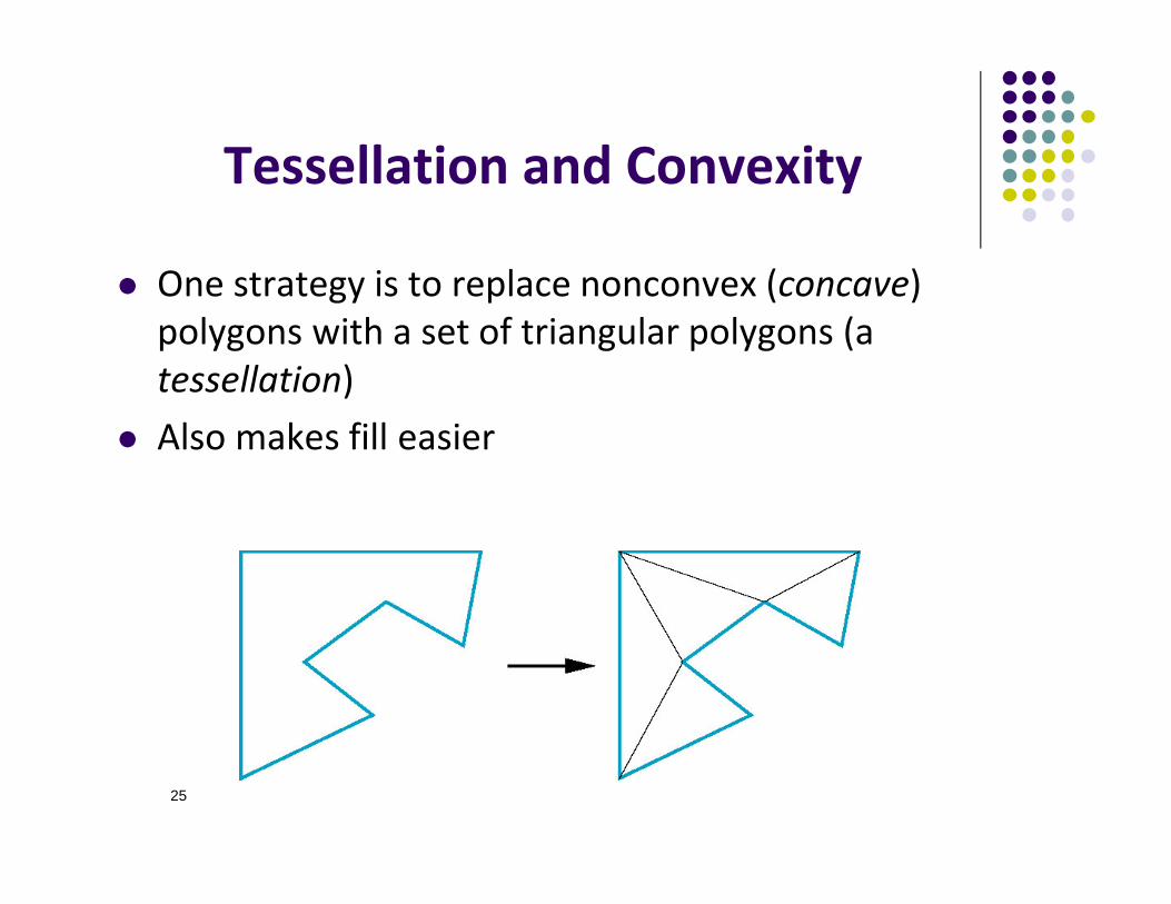
Tessellation and Convexity
One strategy is to replace nonconvex (concave) polygons with a set of triangular polygons (a tessellation)
Also makes fill easier
25
Computer Graphics (CS 4731)Lecture 23: Viewport Transformation
& Hidden Surface Removal
Prof Emmanuel Agu
Computer Science Dept.Worcester Polytechnic Institute (WPI)

Viewport Transformation
After clipping, do viewport transformation
User implements inVertex shader
Manufacturer implementsIn hardware

Viewport Transformation
Maps CVV (x, y) ‐> screen (x, y) coordinates
x
y
width
1-1 x
y
-1
1
height
Canonical View volume
Screen coordinates
glViewport(x,y, width, height)
(x,y)
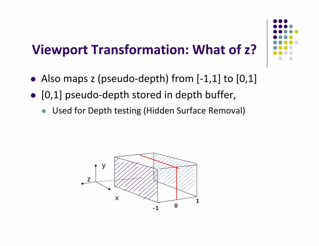
Viewport Transformation: What of z?
Also maps z (pseudo‐depth) from [‐1,1] to [0,1] [0,1] pseudo‐depth stored in depth buffer, Used for Depth testing (Hidden Surface Removal)
x
y
z
-1 01

Hidden surface Removal
Drawing polygonal faces on screen consumes CPU cycles User cannot see every surface in scene To save time, draw only surfaces we see Surfaces we cannot see and elimination methods?
1. Occluded surfaces: hidden surface removal (visibility)
Back face
2. Back faces: back face culling

Hidden surface Removal Surfaces we cannot see and elimination methods:
3. Faces outside view volume: viewing frustrum culling
Classes of HSR techniques: Object space techniques: applied before rasterization Image space techniques: applied after vertices have been
rasterized
Clipped
Not Clipped

Visibility (hidden surface removal)
Overlapping opaque polygons Correct visibility? Draw only the closest polygon (remove the other hidden surfaces)
wrong visibility Correct visibility

Image Space Approach
Start from pixel, work backwards into the scene Through each pixel, (nm for an n x m frame buffer) find closest of k polygons
Complexity O(nmk) Examples: Ray tracing z‐buffer : OpenGL
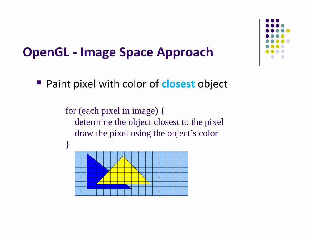
OpenGL ‐ Image Space Approach
Paint pixel with color of closest object
for (each pixel in image) {determine the object closest to the pixel draw the pixel using the object’s color
}

Z buffer Illustration
eye
Z = 0.3
Z = 0.5
Top View
Correct Final image

Z buffer Illustration
1.0 1.0 1.0 1.0
Step 1: Initialize the depth buffer
1.0 1.0 1.0 1.0
1.0 1.0 1.0 1.0
1.0 1.0 1.0 1.0
Largest possiblez values is 1.0

Z buffer Illustration
Step 2: Draw blue polygon (actually order does not affect final result)
eye
Z = 0.3
Z = 0.51.0 1.0 1.0 1.01.0 1.0 1.0 1.0
0.5 0.5 1.0 1.0
0.5 0.5 1.0 1.0
1. Determine group of pixels corresponding to blue polygon2. Figure out z value of blue polygon for each covered pixel (0.5)3. For each covered pixel, z = 0.5 is less than 1.0
1. Smallest z so far = 0.5, color = blue
Z buffer Illustration
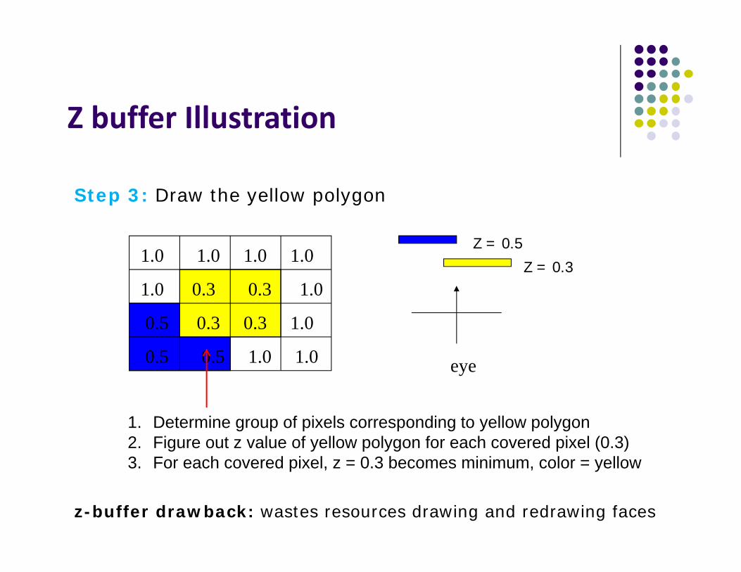
Step 3: Draw the yellow polygon
eye
Z = 0.3
Z = 0.5
1.0 0.3 0.3 1.0
0.5 0.3 0.3 1.0
0.5 0.5 1.0 1.0
z-buffer drawback: wastes resources drawing and redrawing faces
1.0 1.0 1.0 1.0
1. Determine group of pixels corresponding to yellow polygon2. Figure out z value of yellow polygon for each covered pixel (0.3)3. For each covered pixel, z = 0.3 becomes minimum, color = yellow

OpenGL HSR Commands 3 main commands to do HSR
glutInitDisplayMode(GLUT_DEPTH | GLUT_RGB)instructs openGL to create depth buffer
glEnable(GL_DEPTH_TEST) enables depth testing
glClear(GL_COLOR_BUFFER_BIT | GL_DEPTH_BUFFER_BIT) initializes depth buffer every time we draw a new picture

Z‐buffer Algorithm Initialize every pixel’s z value to 1.0 rasterize every polygon For each pixel in polygon, find its z value (interpolate) Track smallest z value so far through each pixel As we rasterize polygon, for each pixel in polygon If polygon’s z through this pixel < current min z through pixel Paint pixel with polygon’s color
Find depth (z) of everypolygon at each pixel

Z (depth) Buffer Algorithm
For each polygon {
for each pixel (x,y) in polygon area {
if (z_polygon_pixel(x,y) < depth_buffer(x,y) ) {
depth_buffer(x,y) = z_polygon_pixel(x,y);
color_buffer(x,y) = polygon color at (x,y)}
}}
Note: know depths at vertices. Interpolate for interior z_polygon_pixel(x, y) depths
Depth of polygon beingrasterized at pixel (x, y)
Largest depth seen so farThrough pixel (x, y)

Perspective Transformation: Z‐Buffer Depth Compression Pseudodepth calculation: Recall we chose parameters (a and b)
to map z from range [near, far] to pseudodepth range[‐1,1]
(-1, -1, 1)
(1, 1, -1)
Canonical View Volume
x
y
z
10100
2)(00
020
00minmax
2
zyx
NFFN
NFNF
bottomtopbottomtop
bottomtopN
leftrightleftright
xxN
These values map z values of original
view volume to [-1, 1] range

Z‐Buffer Depth Compression This mapping is almost linear close to eye Non‐linear further from eye, approaches asymptote Also limited number of bits Thus, two z values close to far plane may map to same pseudodepth: Errors!!
Mapped z
-Pz
1
-1
N
F
PzbaPz
NFNFa
NFFNb
2
Actual z

References
Angel and Shreiner, Interactive Computer Graphics, 6th edition
Hill and Kelley, Computer Graphics using OpenGL, 3rdedition, Chapter 9