Rebuilding of a Classical Robotic System with a Modern ... · Rebuilding of a Classical Robotic...
8
Sensors & Transducers, Vol. 200, Issue 5, May 2016, pp. 16-23 16 Sensors & Transducers © 2016 by IFSA Publishing, S. L. http://www.sensorsportal.com Rebuilding of a Classical Robotic System with a Modern Control Software and Sensor Signals Michail G. PAPOUTSIDAKIS, Eleni SYMEONAKI, Constantinos S. PSOMOPOULOS and Dimitrios I. TSELES Piraues University of Applied Sciences, P. Ralli & Thivon 250, Egaleo, Athens, 12244 Greece Tel.: +30 2105381483, fax: +30 210 5381219 E-mail: [email protected] Received: 18 April 2016 /Accepted: 16 May 2016 /Published: 31 May 2016 Abstract: It is widely known that association between the latest modern technology and robotic manipulators of older ages, has always been of interest to engineers. These machines were equipped with classical sensor devices such as absolute encoders and typical transducers like stepper and servo motors. Considering that present programming tools are very effectual and offer more user friendly interaction, the need for this association is enhanced. The aim of this research project is to present a method via which the SCORBOT ER-III robotic arm will be programmed, efficiently controlled and operated entirely by using a contemporary interface tool. For this purpose the former installed software, although still actual, is substituted by the latest version of LabVIEW program, offering additional stability and proficiency, as well as the ability of controlling and monitoring all robot functions in a more easier and flexible way. On the grounds of this project, there will be records and presentation of the control algorithms performance as well as of the robot feedback signals. Moreover, in the rest of this research paper, there will be a thorough explanation of the main interface control panel by demonstrating characteristic examples of operations and additionally the details of the code generation in block diagram format. Copyright © 2016 IFSA Publishing, S. L. Keywords: Robot sensors, Robotic arm controlling, Feedback signals, Control algorithms, User interface, Versatile programming platform, Safety precautions. 1. Introduction Robotic equipment and robots established during the '90s in particular, are still fully functional in several research laboratories and in industrial facilities as well. The control interfaces that were coming along with such equipment are still operational too, although their limitations of usage turn the robot programming rather complicated. Considering the reliable structure of robotic manipulators built during the past decades, their support with an up to date interface, intended for programming and controlling the robot's operation, seems to be essential. Robotic manipulators of this kind are dispensed with a variety of options regarding peripherals, in order to manage and perform more applications such as pick-and-place, size comparison, masses transfer and many more. On top of all robot equipment components, is the main controller box which is connected to a computer unit and can be programmed according to the demands of the user, although the interfacing abilities are quite limited due to its operation in an old environment such as DOS. Moreover, the manipulator comprises advanced electrical components such as DC and servo motors for achieving operation in high torque and ensuring that all requirements of the arm freedom http://www.sensorsportal.com/HTML/DIGEST/P_2819.htm
Transcript of Rebuilding of a Classical Robotic System with a Modern ... · Rebuilding of a Classical Robotic...
Sensors & Transducers, Vol. 200, Issue 5, May 2016, pp. 16-23
16
Sensors & Transducers© 2016 by IFSA Publishing, S. L.
http://www.sensorsportal.com
Rebuilding of a Classical Robotic System with a Modern Control Software and Sensor Signals
Michail G. PAPOUTSIDAKIS, Eleni SYMEONAKI,
Constantinos S. PSOMOPOULOS and Dimitrios I. TSELES Piraues University of Applied Sciences, P. Ralli & Thivon 250, Egaleo, Athens, 12244 Greece
Tel.: +30 2105381483, fax: +30 210 5381219 E-mail: [email protected]
Received: 18 April 2016 /Accepted: 16 May 2016 /Published: 31 May 2016 Abstract: It is widely known that association between the latest modern technology and robotic manipulators of older ages, has always been of interest to engineers. These machines were equipped with classical sensor devices such as absolute encoders and typical transducers like stepper and servo motors. Considering that present programming tools are very effectual and offer more user friendly interaction, the need for this association is enhanced. The aim of this research project is to present a method via which the SCORBOT ER-III robotic arm will be programmed, efficiently controlled and operated entirely by using a contemporary interface tool. For this purpose the former installed software, although still actual, is substituted by the latest version of LabVIEW program, offering additional stability and proficiency, as well as the ability of controlling and monitoring all robot functions in a more easier and flexible way. On the grounds of this project, there will be records and presentation of the control algorithms performance as well as of the robot feedback signals. Moreover, in the rest of this research paper, there will be a thorough explanation of the main interface control panel by demonstrating characteristic examples of operations and additionally the details of the code generation in block diagram format. Copyright © 2016 IFSA Publishing, S. L. Keywords: Robot sensors, Robotic arm controlling, Feedback signals, Control algorithms, User interface, Versatile programming platform, Safety precautions.
1. Introduction
Robotic equipment and robots established during the '90s in particular, are still fully functional in several research laboratories and in industrial facilities as well. The control interfaces that were coming along with such equipment are still operational too, although their limitations of usage turn the robot programming rather complicated. Considering the reliable structure of robotic manipulators built during the past decades, their support with an up to date interface, intended for programming and controlling the robot's operation, seems to be essential. Robotic manipulators of this
kind are dispensed with a variety of options regarding peripherals, in order to manage and perform more applications such as pick-and-place, size comparison, masses transfer and many more.
On top of all robot equipment components, is the main controller box which is connected to a computer unit and can be programmed according to the demands of the user, although the interfacing abilities are quite limited due to its operation in an old environment such as DOS. Moreover, the manipulator comprises advanced electrical components such as DC and servo motors for achieving operation in high torque and ensuring that all requirements of the arm freedom
http://www.sensorsportal.com/HTML/DIGEST/P_2819.htm

Sensors & Transducers, Vol. 200, Issue 5, May 2016, pp. 16-23
17
degrees will be met. The electrical components along with the
mechanical parts (connectors, joints, etc.) are all linked via an extensive network of wires and electrical safety devices. As the SCORBOT ER-III is a fully controllable apparatus, electrical sensors are also involved in the closed loop system. In addition encoders/ absolute encoders are attached to each motor type granting real-time data about the operation of the robot, the movement and displacement speed as well as the status of the gripper.
In this research project, the former installed control software, although still actual, is now substituted by a more stable and proficient one. For this purpose, the hardware which was already described will be combined with the latest version of LabView software, offering to the user the ability of controlling and monitoring all robot functions in a more easier and flexible way. In order to prove the efficiency of this software, several experiments were conducted, the results of which are going to be presented and described in this paper through particular examples. Additionally there will be a thorough explanation of the main interface control panel as well as a demonstration of results concerning the communication between the user and the system. The particular robot, as an advanced electrical system, even while going through a second decade of usage, consists of several controllable electrical components which justify the concept for its appliance even up to the present time. This purpose is here in achieved by combining this dependable electrical equipment unit with the technology of modern software. LabView is a graphical programming software which was originally established in 1986 by National Instruments Corporation and is being constantly upgraded since then. It is designed for satisfying the needs of integrated engineering tasks such as interfacing computers with instrumental equipment, acquiring, saving and screening data as well as offering an effective user interface through algorithms or programs developing in a graphical environment. As several researchers have included this software in their projects over the years, it has already demonstrated its advantages in tasks corresponding to the one presented here in.
There is a significant number of indicative reports regarding LabView applications in autonomous robotic vehicles programming as well as monitoring its performance. There are respectively mentioned the researches of Anderson Pereira Correia, et al., (see [1]) and Ramirez-Cortes J. M., et al., (see [2]) who achieved complete mobile robot control, autonomous navigation and real-time image display by using the total of LabView features. Furthermore, great research has been performed on the subject of interconnecting various types of robotic arms and manipulators to this sophisticated software. For example Shobhita Ann Job, et al. (see [3]) introduced a LabView based control method for managing signals of a pick-and-place 4 axis arm, C. Chandra Mouli, et al. (see [4]), achieved the control of a servo operating heavy duty
robotic manipulator with 5 freedom degrees while other researchers as Roland Szabo and Aurel Gontean (see [5]) came out with a face recognition application in which a 4 axis arm was controlled by stereoscopic cameras. Each one of these projects marked excessive results and LabView was recommended by researchers as the best available software for such assignments. On the grounds of this research project, the above mentioned work presenting in bibliography, was taken into account, as well as the work of Saeid Moslehpour, et al. (see [6]), who managed successfully to develop a short of intercourse between LabView and SCORBOT ER-III. In the following sections of this project, this interplay is further extended regarding its efficiency, whereas additional potentials of controlling and automation concerning system to user safety, are presented for the first time.
2. System Description
On its most common form the robotic manipulator is constituted by the arm and a controller, as it is illustrated in the Fig. 1 below. The SCORBOT ER-III is constructed with standardized materials and can be electronically controlled. More than that, throughout its constant use during the past decades, it has earned the distinction of being a safe device when operated in a proper way.
Fig. 1. SCORBOT ER-III robot arm and controller box.
The ER-III is a 5 axes robot arm with 5 freedom degrees meaning there are 5 control joints for its manipulation that offer additional control and skillfulness. In Fig. 2 all possible rotary movements are illustrated. The first axis refers to the base which enables the robot to rotate horizontally around the stand where it is fastened to. The second axis refers to the shoulder while the third one refers to the elbow, which operates similarly to the shoulder. The fourth axis refers to the wrist and is frequently described as 2 axes in the same location. The robotic wrist is able to perform up and down movement in a waving motion just like a human wrist does. Finally the fifth axis
Sensors & Transducers, Vol. 200, Issue 5, May 2016, pp. 16-23
18
enables the wrist to move in a rotational, sideways motion. In some robots this twisting motion is assisted by beveled gears in the wrist and can be an entire 360 degrees rotation or more. The robotic arm ends into a pair of grippers which are able to opened and close. Although the grippers (effectors) are not referred to a movement axis, are controlled much alike the rest of the components.
Fig. 2. SCORBOT ER-III robot arm motion schematics.
The controller box contains the required electronic control parts for interfacing the software program with the robotic arm. It controls all of the motors and the effectors along with the limit switch. There are also switches for performing motors and lights tests, as found in [7]. The ability of installing and controlling additional parts such as buzzers, lights, etc. is given as well.
The SCORBOT ER-III is controlled by a computer software provided by the manufacturer, which still in most cases operates in a DOS format although it has been upgraded several times. As soon as the computer unit with which the robot is connected, turns on, the software, named “SCORBASE”, will automatically load and the main program window illustrated in Fig. 3 will appear.
Fig. 3. “SCORBASE” arm teach positions main menu. The limitations of using control and robotic
devices in DOS platform are more than nowadays
programming technology can afford. The lack of animation, signal feedback monitoring, human interacting, and moreover safety precautions measures cannot be hosted or handled in such old programming environments. At the top of that problem, the user in most of the cases in order to type the robot control code, he was obliged to prepare a flowchart of his algorithm, as in Fig. 4, and then transform routines and commands in SCORBASE environment. This process was extremely time consuming and in many cases shown increased fault possibilities in the commands transformation.
Fig. 4. “SCORBASE” typical program structure.
A significant attempt to improve that was implemented in the close past, by replacing the old DOS based version with a Windows platform for programming the SCORBOT arm. This new interface was more flexible than the old one and could run in most personal computers of the engineers. Although the need of the older type of programming and code entry was still there, the existence of buttons for the robotic arm motion, made the interface a lot more user friendly, as Fig. 5 illustrates.
Fig. 5. “SCORBASE” interface based on Windows environment.

Sensors & Transducers, Vol. 200, Issue 5, May 2016, pp. 16-23
19
At this point, the reason of undertaking this project
must once again be mentioned. The interface software presented by the manufacturer lacks in performance, feedback signals analysis and last but not least safety predictions design. Consequently, it was decided to maintain the arm as well as the controller and introduce additionally a user friendly interface, like LabView, offering a great amount of potentials and considerably improved efficiency.
3. Innovative Interface Design
As the use of industrial robots is constantly expanding into new kinds of inspection as well as pick-and-place applications, a more adjustable, accurate, and delicate part handling is required.
The necessity for higher performance and more intelligent control is increased by the usage of robotic arms in laboratory automation projects and automated testing applications or even as manipulators attached to autonomous vehicles. This will allow robots adaption to the continuously modifying conditions by interacting with the environment, easily adjusting the motion profiles, handling delicate items, randomly positioning (locating, handling, picking and placing) the components and finally operating in a safe way. This kind of applications require more intelligent robots, able to communicate with their environments through data acquisition and feedback signals.
The LabVIEW system design software by National Instruments is opening the way of new applications for industrial or laboratory robots by combining control, data acquisition, and human machine interfaces (HMIs) into an integrated, user friendly environment. Experimenting with this software and establishing interaction with the standardized SCORBOT ER-III controller box via the provided RS-232 port was a great challenge. The decision made was to initiate the process from elementary manipulator movements and gradually upgrade the LabView code in order to finally establish more complicated tasks of the robotic motion. In Fig. 6 there is an illustration of the primary interface format involving a simple serial port communication scheme and buttons for the right/left rotational motion of the robot base. A motor speed and step regulator for elemental open loop control is also included.
Fig. 6. Layout of the interface panel for elemental open loop control.
The code which is required for the support of this first application includes routines and loops consisting of several commands, toolboxes and libraries as well. In order to proceed further and establish more advanced applications such as speed and step control, not only of the base but also of all the arm axes, the code had to be substantially increased while a user interface window hosting all these operational regulators had to be concurrently built. At this point all of the 8 servomotors encoders (7 and 1 for the arm and a peripheral conveyor respectively) have to be employed, the control is based upon closed loop feedback signals and each serial port reading regarding the status of the robot is displayed in an independent window. The step signals which the user transmits to the robot controller via LabView code are determined by 2 parameters, one for the pulse generation and another one for the refresh rate in msec.
Applying this method, complete and highly accurate speed and step control of the robotic arm is succeeded whereas all freedom degrees are involved and real-time status signals are being returned as feedback to the user. Considering that this LabView code is enormous in blocks format and impossible to fit in a paper like this one, only the central and representational sections of it are illustrated in Fig. 7 focusing on the one where the control loop of the 8 servomotors speed is programmed.
Each robotic manipulator, similar to the size and torque of SCORBOT ER-III, is provided by the manufacturer with a pre-programmed default command which is called “home position” and it is used for setting the initial position of the arm as well as for storage purposes. In order to compose this command in LabView another part of code had to be added as illustrated in Fig. 8. According to user's requirements, once the button “home position” is activated in the interface panel, the robot ends any task being performed at the time and returns to its initial position in an uninterrupted procedure.
The layout of the main interface panel which is used for the operation by the user, is illustrated in Fig. 9. In there, one can observe the 8 regulators which are used for setting the speed and the step for each one of the 7 servomotors that are responsible for moving the arm as well as the 8th that operates the peripheral conveyor. On the upper side of the panel a window is placed for monitoring serial port's recordings while the “home position” button is placed on the top left side, as aforementioned. In addition there is a significant number of position limit switches which are adjusted on the robot providing information about the arm's location and constituting input signals to the controller.
Incorporating safety precautionary measures in this type of robotic devices is of high importance and in this case, it was taken into serious account. If for example a human or a random obstacle hit the arm while this operating it would be of great hazard so much for the user as for the items transferred by the robot as well.

Sensors & Transducers, Vol. 200, Issue 5, May 2016, pp. 16-23
20
Fig. 7. LabView code for speed control of the 8 motors.
Fig. 8. Robot's “home position” command in LabView code.
Fig. 9. Layout of the main interface panel for programming.

Sensors & Transducers, Vol. 200, Issue 5, May 2016, pp. 16-23
21
For this reason, an automated process was designed and included into the code in an effort to avoid such accidents. When an encoder stops transmitting data, in case of a forced standstill of the arm for example, a warning message appears in the interface monitor and the robot simultaneously freezes. The user is able to decide afterwards whether to end the process or return the robot to its initial position.
A case loop inside a while loop representing the status control of all robot limit switches has already been shown in Fig. 8. Furthermore, another part of syntax was composed and added to the rest of the code in order to read all encoders signals and stop immediately the arm operation in case the status transmission of an encoder is interrupted. This part of code is illustrated in Fig. 10 so as to show that safety precautions in operation were taken under serious consideration during the performance of experiments with the plant. In this part of LAbview code, there is a successful design of taking safety precautionary measures and prevent any possible cause of accident to users due to interruption, deterrence or crash of the robot operation, both rotation trends (clockwise/anticlockwise) of each encoder.
As authors are aware of, this kind of safety precautionary feature has never been included before in any of the existing LabView codes, increasing further in this way the software efficiency for applications concerning robotic control. Custom applications such as pick-and-place, random obstacles size comparison, transferring obstacles to the conveyor according to dimensioning and many more were not only designed but also conducted in this interface. To achieve this, more parts of code that are rather oversized to be fitted in this paper, were composed and tested. In each case the response of the robot arm was more than satisfactory enhancing the overall concept that this interface environment is the
most adequate one for performing this kind of tasks than any other.
In order to expand the research work and prove sufficient enough the system capabilities, an innovative experiment was tested and implemented.
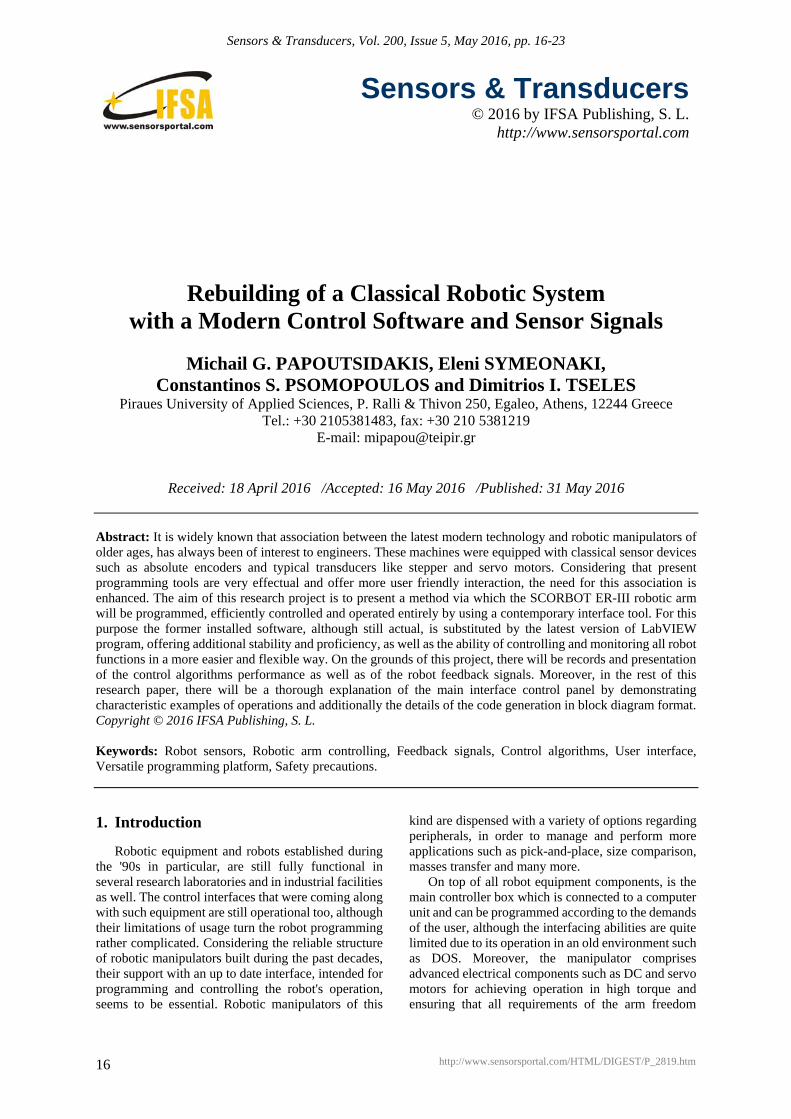
A common procedure of such robotic arms in industry or in packaging pipelines, is the so-called "pick and place" process for items and goods. The scientific question here is obviously not the way this can be done but furthermore how can the user operate the system under 100 % safety in case an unexpected factor (human or random obstacle) interacts with the robot by accident. A new control algorithm was designed for the task as well as a new complementary interface window. This new programming scenario includes the acute stopping of the robotic arm operation and a red light flashing on the new designed interface window, as in Fig. 11.
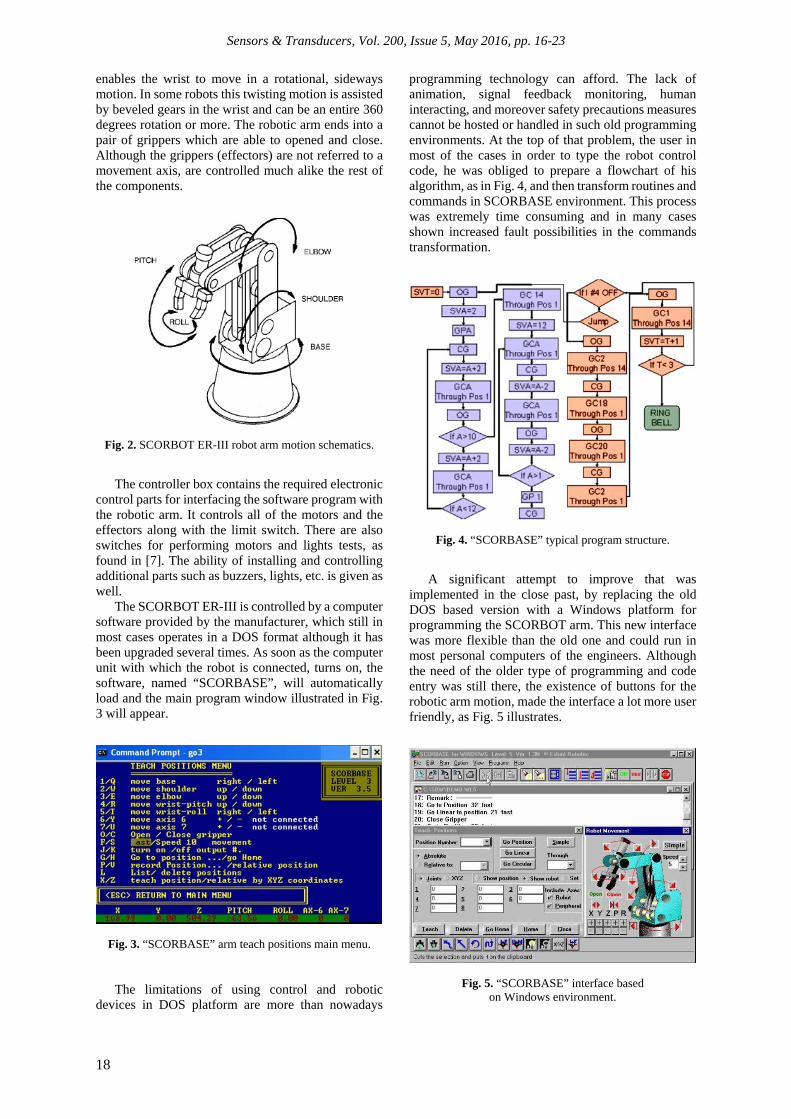
At that stage, the algorithm provides the user with two different options on his demand, either to continue the pre-programmed operation which was downloaded to the robotic arm's memory previously, or to stop and cancel the operation and a total erase of the robot's memory. After that the user can operate the robot all the way from the beginning, set to home position, re-program it for next procedure etc. This multi-functional algorithm is based on a continuous real time comparison of the instant value of all motion axes encoders with the precise previous value of each encoder. This scenario is undertaken via the loops illustrated in Fig. 12, and to any prospect ensure not only the user's safety but also provide him the ability to decide what to do with the rest of the packaging or pick and place operation of the system. Once again like in previous figures, Fig. 12 provides only a part of the whole algorithm due to its huge size but, in any case, it contains all critical data referring to the main loops of the task.
Fig. 10. Safety precaution code including both rotation trends.
Sensors & Transducers, Vol. 200, Issue 5, May 2016, pp. 16-23
22
Fig. 11. Interface window for manipulations in case of operation distractions.
Fig. 12. Safety precaution code including both rotation trends.
4. Conclusions
The scientific question of this research work which arose naturally from earlier work of the authors, as in [8], was if an old though robust and well known robotic arm can be used in linkage with modern control software. In this paper, the challenge was expanded to make a user friendly interface to host also precautions and procedures for high safety standards and multi-optional operation of the robotic arm. After
several months of performing extended experiments with the plant, a number of conclusions has derived and should be reported.
Critical factors which determine the efficiency of the method herein suggested, such as accuracy and repeatability were maintained in high standards for every operation mode, even more than the original ones which are offered by the manufacturer. Consequently, this updated interface design has resulted to be more sufficient than the older DOS

Sensors & Transducers, Vol. 200, Issue 5, May 2016, pp. 16-23
23
operated SCORBOT ER-III software turning the programming process to be fairly effortless for the user. Additionally, there is a significant innovation in this robot's operation using LabView interface, regarding the feature of safety precautions that was presented earlier in a detailed way, giving a great advantage to this method compared to any other programming process.
The innovation of this user safety algorithm in order all robot axes movements to be memorized and benefit the user to keep on the process from the exact point the robot was stopped and finish its task rather than aborting it, will be further investigated in the close future. In fact the multiplication of feedback signals in the interface by employing displacement sensors (position sensors) around the arm will also be implemented. LabView is adequately able to manage all these inputs in a successful way, allowing the user to be provided with more real-time data as far it concerns the robot position. This feature gives a great advantage to the system and satisfies the original hypothesis of this project, whether or not a sufficient benefit may come of associating old yet reliable hardware and modernized programming software.
Acknowledgements
All authors would like to thank the Postgraduate Program of Studies "Automation for Production and Services", hosted by Department of Automation Engineering at Piraeus University of Applied Sciences, for the financial support to undertake this research work.
References [1]. Anderson Pereira Correia, Carlos Humberto Llanos,
Rodrigo Williams de Carvalho, Sadek Alfaro, A Control Design Approach for Controlling an Autonomous Vehicle with FPGAs, Journal of Computers, Vol. 5, No. 3, 2010, pp. 360-372.
[2]. Ramirez-Cortes J. M., Gomez-Gil P., Martinez-Carballido J., Lopez-Larios F., A LabVIEW-based Autonomous Vehicle Navigation System using Robot Vision and Fuzzy Control, Journal of Engineering Investigation in Technology, Vol. 12, No. 2, 2011, pp. 129-136.
[3]. Shobhita Ann Job, R. Jegan, Melwin Abraham C., OWI-535 EDGE Robotic Arm Control Using ElectroMyoGram (EMG) Signals, International Journal of Innovative Technology and Exploring Engineering, Vol. 2, No. 6, 2013, pp. 282-286.
[4]. C. Chandra Mouli, P. Jyothi, K. Nagabhushan Raju, C. Nagaraja, Design and Implementation of Robot Arm Control Using LabView and Arm Controller, IOSR Journal of Electrical and Electronics Engineering, Vol. 6, No. 5, 2013, pp. 80-84.
[5]. Roland Szabo, Aurel Gontean, Full 3D Robotic Arm Control with Stereo Cameras Made in LabView, in Proceedings of the Position Papers of the Federated Conference on Computer Science and Information Systems, 2013, pp. 37-42.
[6]. Saeid Moslehpour, Candace Odom, Tyrell Barrett, Matt Brawn, Scorbot ER-III Robot, The Technology Interface Journal, Vol. 10, No. 3, 2010, pp. 1-19.
[7]. SCORBOT-ER III, User's Manual 6th Edition, Eshed Robotec, 1999.
[8]. Michail Papoutsidakis, George Chamilothoris, D. Piromalis, Modern Control Interface for SCORBOT ER-III Robot, in Proceedings of the IEEE International Symposium on Fundamentals of Electrical Engineering, Bucharest, Romania, November 28-29, 2014, pp. 1-5.
___________________
2016 Copyright ©, International Frequency Sensor Association (IFSA) Publishing, S. L. All rights reserved. (http://www.sensorsportal.com)