PERSON MENU VEHICLE MENU DRIVER MENU ACCIDENT MENU US Department Of
REBLE610-ODU 31/01/2014
www.elber.com
Page 1 of 60 Version 1.3 B
REBLE610-ODU
User Manual
REBLE610-ODU Microwave link
Page 2 of 60 Version 1.3 B
1 Summary
USER MANUAL ........................................................................................................................................................... 1
2 FIGURE INDEX .................................................................................................................................................... 4
3 SAFETY REGULATIONS. ....................................................................................................................................... 7
3.1 TREATMENT OF ELECTRICAL SHOCKS. ............................................................................................................... 7
3.2 TREATMENT OF ELECTRICAL BURNS. ................................................................................................................. 8
4 GENERAL DESCRIPTION. ..................................................................................................................................... 8
5 TECHNICAL SPECIFICATIONS. .............................................................................................................................. 9
5.1 MODEM DETAILS. ................................................................................................................................................. 10
5.2 I/O SIGNALS. ....................................................................................................................................................... 10
5.3 GENERAL SPECIFICATIONS ...................................................................................................................................... 10
5.4 MECHANICAL SPECIFICATIONS. ............................................................................................................................... 10
6 INSTALLATION. ..................................................................................................................................................11
7 USER INTERFACE. ..............................................................................................................................................11
7.1 MAIN MENU. ...................................................................................................................................................... 11
7.2 SUMMARY MENU. ................................................................................................................................................ 12
7.3 MENU UPROCESSOR (UP). ..................................................................................................................................... 13
7.3.1 MicroProcessor submenu. ........................................................................................................................... 13
7.3.2 Menu Setup - System Time. ......................................................................................................................... 13
7.3.3 Menu Setup - Touch Screen Calibration. ..................................................................................................... 13
7.3.4 Menu Setup - Reset. .................................................................................................................................... 14
7.3.5 Menu Net - Network parameters. ............................................................................................................... 14
7.3.6 Menu Misc - General information 1/2. ....................................................................................................... 15
7.3.7 Menu Misc - General information 2/2. ....................................................................................................... 15
7.3.8 Menu Misc - Modules. ................................................................................................................................. 16
7.4 MENU MODEM (MODEM UC). .............................................................................................................................. 18
7.4.1 Modem submenu. ....................................................................................................................................... 19
7.4.2 Modem configuration menu. ...................................................................................................................... 19
7.4.3 Modem measurements menu. .................................................................................................................... 19
7.4.4 Modem alarms menu. ................................................................................................................................. 21
7.4.5 Modem general menu. ................................................................................................................................ 23
7.5 MENU I/O (IO). .................................................................................................................................................. 23
7.5.1 I/O submenu. .............................................................................................................................................. 23
7.5.2 Ethernet menu. ........................................................................................................................................... 24
7.5.3 SMPTE310 ASI menu. .................................................................................................................................. 24
7.5.4 E1 menu. ..................................................................................................................................................... 26

REBLE610-ODU Microwave link
Page 3 of 60 Version 1.3 B
7.5.5 TRANSIT menu. ............................................................................................................................................ 27
7.6 MENU TRANSMITTER (TX). .................................................................................................................................... 28
7.7 MENU RECEIVER (RX). .......................................................................................................................................... 28
7.8 MENU COMMUNICATOR. ...................................................................................................................................... 29
7.8.1 Communicator submenu. ............................................................................................................................ 29
7.8.2 Menu Status Communicator. ...................................................................................................................... 29
7.8.3 Menu Configuration Communicator. .......................................................................................................... 30
7.8.4 Menu Head.................................................................................................................................................. 31
7.8.5 Menu Alarm Communicator........................................................................................................................ 31
7.9 MENU POWER SUPPLY (PS). .................................................................................................................................. 32
8 WEB INTERFACE. ...............................................................................................................................................32
8.1 STATUS. ............................................................................................................................................................. 33
8.1.1 Status-Controller. ........................................................................................................................................ 33
8.1.2 Status-Modem. ........................................................................................................................................... 34
8.2 STATUS-INTERFACE. .............................................................................................................................................. 36
8.2.1 Status-Transmitter. ..................................................................................................................................... 38
8.2.2 Status-Receiver. .......................................................................................................................................... 38
8.3 TAB CONTROLLER. ................................................................................................................................................ 39
8.3.1 Controller – Coil fans. .................................................................................................................................. 39
8.3.2 Controller – Customer. ................................................................................................................................ 40
8.3.3 Controller – Network. .................................................................................................................................. 41
8.3.4 Controller – Trap Manager. ........................................................................................................................ 41
8.3.5 Controller – Tools. ....................................................................................................................................... 44
8.3.6 Controller – Password management. .......................................................................................................... 44
8.4 TAB SLOT............................................................................................................................................................ 45
8.4.1 Slot – Modem. ............................................................................................................................................. 45
8.4.2 Slot – Interface. ........................................................................................................................................... 49
8.4.3 Slot – TX. ..................................................................................................................................................... 51
8.4.4 Slot – Rx....................................................................................................................................................... 52
8.4.5 Slot – Communicator. .................................................................................................................................. 53
8.5 TAB UPGRADE. .................................................................................................................................................... 55
8.6 TAB LOG. ............................................................................................................................................................ 56
9 MECHANICS. ......................................................................................................................................................58
9.1 FRONT PANEL. ..................................................................................................................................................... 58
9.2 BACK PANEL. ....................................................................................................................................................... 59
9.3 RF HEAD. ........................................................................................................................................................... 60
REBLE610-ODU Microwave link
Page 4 of 60 Version 1.3 B
2 Figure Index
FIGURE 1: RESUSCITATION DETAIL – 1. ........................................................................................................................................ 7
FIGURE 2: RESUSCITATION DETAIL – 2. ........................................................................................................................................ 7
FIGURE 3: RESUSCITATION DETAIL – 3. ........................................................................................................................................ 7
FIGURE 4: RESUSCITATION DETAIL – 4. ........................................................................................................................................ 7
FIGURE 5: RESUSCITATION DETAIL – 5. ........................................................................................................................................ 7
FIGURE 6: MAIN MENU FD. .................................................................................................................................................... 12
FIGURE 7: MAIN MENU TX. ..................................................................................................................................................... 12
FIGURE 8: MAIN MENU RX. ..................................................................................................................................................... 12
FIGURE 9: SUMMARY MENU FD. .............................................................................................................................................. 12
FIGURE 10: MICROPROCESSOR SUBMENU. ................................................................................................................................. 13
FIGURE 11: SYSTEM TIME SETTING MENU. .................................................................................................................................. 13
FIGURE 12: VIRTUAL KEYPAD. .................................................................................................................................................. 13
FIGURE 13: TOUCH SCREEN CALIBRATION MENU. ........................................................................................................................ 14
FIGURE 14: RESET MENU. ....................................................................................................................................................... 14
FIGURE 15: NETWORK PARAMETERS MENU. ............................................................................................................................... 15
FIGURE 16: GENERAL INFO MENU 1/2. ...................................................................................................................................... 15
FIGURE 17: GENERAL INFO MENU 2/2. ...................................................................................................................................... 16
FIGURE 18: GENERAL PURPOSE INFORMATION CONTROLLER. ......................................................................................................... 16
FIGURE 19: GENERAL PURPOSE INFORMATION MODEM................................................................................................................. 17
FIGURE 20: GENERAL PURPOSE I/O INTERFACE INFORMATION. ...................................................................................................... 17
FIGURE 21: GENERAL PURPOSE INFORMATION RX. ....................................................................................................................... 18
FIGURE 22: GENERAL PURPOSE INFORMATION TX. ....................................................................................................................... 18
FIGURE 23: MODEM SUBMENU. ............................................................................................................................................... 19
FIGURE 24: MODEM FD CONFIGURATION MENU. ........................................................................................................................ 19
FIGURE 25: MODEM FD MEASUREMENT MENU. ......................................................................................................................... 20
FIGURE 26: MODEM TX MEASUREMENT MENU. .......................................................................................................................... 20
FIGURE 27: MODEM RX MEASUREMENT MENU. .......................................................................................................................... 20
FIGURE 28: MODEM FD MEASUREMENTS MENU (2). ................................................................................................................... 20
FIGURE 29: MODEM TX MEASUREMENTS MENU (2). ................................................................................................................... 20
FIGURE 30: MODEM RX MEASUREMENTS MENU (2). ................................................................................................................... 20
FIGURE 31: MODEM XPIC MEASUREMENTS MENU FD. ................................................................................................................ 21
FIGURE 32: MODEM XPIC MEASUREMENTS MENU TX. ................................................................................................................. 21
FIGURE 33: MODEM XPIC MEASUREMENTS MENU RX. ................................................................................................................ 21
FIGURE 34: MODEM ALARMS MENU FD. ................................................................................................................................... 21
FIGURE 35: MODEM ALARMS MENU TX. .................................................................................................................................... 21
FIGURE 36: MODEM ALARMS MENU RX. .................................................................................................................................... 21
FIGURE 37: MODEM GENERAL MENU FD. .................................................................................................................................. 23
REBLE610-ODU Microwave link
Page 5 of 60 Version 1.3 B
FIGURE 38: MODEM GENERAL MENU TX. ................................................................................................................................... 23
FIGURE 39: MODEM GENERAL MENU RX.................................................................................................................................... 23
FIGURE 40: I/O SUB-MENU. .................................................................................................................................................... 23
FIGURE 41: MENU ETHERNET. ................................................................................................................................................. 24
FIGURE 42: GENERAL SMPTE310/ASI MENU. .......................................................................................................................... 24
FIGURE 43: BNC CONNECTOR CONFIGURATION AND STATUS MENU. ............................................................................................... 25
FIGURE 44: GENERAL E1 PORTS ............................................................................................................................................... 26
FIGURE 45: RJ48C CONNECTOR CONFIGURATION AND STATUS MENU. ............................................................................................. 26
FIGURE 46: GENERAL TRANSIT MENU...................................................................................................................................... 27
FIGURE 47: TRANSIT CONFIGURATION AND STATUS MENU. .......................................................................................................... 27
FIGURE 48: TRANSMITTER MENU. ............................................................................................................................................. 28
FIGURE 49: RECEIVER MENU. ................................................................................................................................................... 29
FIGURE 50: MENU COMM LINK. ............................................................................................................................................... 29
FIGURE 51: MENU STATUS COMMUNICATOR. ............................................................................................................................. 30
FIGURE 52: MENU CONFIGURATION COMMUNICATOR. ................................................................................................................. 30
FIGURE 53: POWER SUPPLY MENU............................................................................................................................................ 32
FIGURE 54: ICON POWER SUPPLY WITH CONTINUOUS CURRENT, PRIMARY POSITION. .......................................................................... 32
FIGURE 55: ICON POWER SUPPLY WITH CONTINUOUS CURRENT, SECONDARY POSITION. ...................................................................... 32
FIGURE 56: ICON POWER SUPPLY WITH ALTERNATING CURRENT, PRIMARY POSITION. .......................................................................... 32
FIGURE 57: ICON POWER SUPPLY WITH ALT ALTERNATING CURRENT, SECONDARY POSITION. ................................................................. 32
FIGURE 58: WEB INTERFACE LOGIN PAGE. .................................................................................................................................. 33
FIGURE 59: WEB STATUS FORM – CONTROLLER........................................................................................................................... 33
FIGURE 60: WEB STATUS FORM – CONTROLLER FANS. .................................................................................................................. 34
FIGURE 61: WEB STATUS FORM – MODEM LOCKED. ..................................................................................................................... 35
FIGURE 62: WEB STATUS FORM – MODEM UNLOCKED.................................................................................................................. 35
FIGURE 63: WEB STATUS FORM – INTERFACE BNC STATUS. .......................................................................................................... 36
FIGURE 64: WEB STATUS FORM – INTERFACE RJ48C STATUS. ....................................................................................................... 37
FIGURE 65: WEB STATUS FORM – TX. ....................................................................................................................................... 38
FIGURE 66: WEB STATUS FORM – RX. ....................................................................................................................................... 38
FIGURE 67: WEB CONTROLLER FORM – FANS. ............................................................................................................................. 39
FIGURE 68: WEB CONTROLLER FORM – CUSTOMER INFO. ............................................................................................................. 40
FIGURE 69: WEB CONTROLLER FORM – NETWORK PARAMETERS. ................................................................................................... 41
FIGURE 70: WEB CONTROLLER FORM – MODEM SNMP TRAPS CONFIGURATION. ............................................................................. 42
FIGURE 71: WEB CONTROLLER FORM – DATA INTERFACE SNMP TRAPS CONFIGURATION. .................................................................. 42
FIGURE 72: WEB CONTROLLER FORM – BASEBAND SIGNALS SNMP TRAPS CONFIGURATION. ............................................................... 42
FIGURE 73: WEB CONTROLLER FORM – RECEIVER SNMP TRAPS CONFIGURATION. ............................................................................ 42
FIGURE 74: WEB CONTROLLER FORM – TRANSMITTER SNMP TRAPS CONFIGURATION. ...................................................................... 42
FIGURE 75: WEB CONTROLLER FORM – CONTROLLER SNMP TRAPS CONFIGURATION. ....................................................................... 42
FIGURE 76: WEB CONTROLLER FORM – TRAP DESTINATION CONFIGURATION. .................................................................................. 43
REBLE610-ODU Microwave link
Page 6 of 60 Version 1.3 B
FIGURE 77: WEB CONTROLLER FORM – GENERAL INFO AND TOOLS. ................................................................................................ 44
FIGURE 78: WEB CONTROLLER FORM –PASSWORD MANAGEMENT. ................................................................................................ 44
FIGURE 79: WEB SLOT MODEM FORM – STATUS. ......................................................................................................................... 45
FIGURE 80: WEB SLOT MODEM FORM – MSE GRAPHIC. ............................................................................................................... 46
FIGURE 81: WEB SLOT MODEM FORM – TEMPERATURE MANAGEMENT. .......................................................................................... 46
FIGURE 82: WEB SLOT MODEM FORM – PROFILE MANAGEMENT. ................................................................................................... 46
FIGURE 83: WEB SLOT MODEM FORM – PROFILE MANAGEMENT EXPANDED. .................................................................................... 47
FIGURE 84: WEB SLOT MODEM FORM – OPERATIONAL MODE MANAGEMENT. ................................................................................. 47
FIGURE 85: WEB SLOT MODEM FORM – OPERATIONAL MODE MANAGEMENT EXPANDED. .................................................................. 47
FIGURE 86: WEB SLOT INTERFACE FORM – STATUS. ..................................................................................................................... 49
FIGURE 87: WEB SLOT INTERFACE FORM – INPUT/OUTPUT PORTS MANAGEMENT. ............................................................................. 49
FIGURE 88: WEB SLOT INTERFACE FORM – ETHERNET PORT MANAGEMENT. ..................................................................................... 50
FIGURE 89: WEB SLOT INTERFACE FORM – TRANSIT MANAGEMENT. ................................................................................................ 50
FIGURE 90: WEB SLOT TX FORM – STATUS. ................................................................................................................................ 51
FIGURE 91: WEB SLOT TX FORM – TEMPERATURE MANAGEMENT. ................................................................................................. 51
FIGURE 92: WEB SLOT TX FORM – POWER MANAGEMENT. ........................................................................................................... 52
FIGURE 93: WEB SLOT TX FORM – FREQUENCY. .......................................................................................................................... 52
FIGURE 94: WEB SLOT RX FORM – STATUS. ................................................................................................................................ 52
FIGURE 95: WEB SLOT RX FORM – RSSI GRAPHIC. ...................................................................................................................... 53
FIGURE 96: WEB SLOT RX FORM – FREQUENCY. .......................................................................................................................... 53
FIGURE 97: WEB SLOT RX FORM –TEMPERATURE MANAGEMENT. .................................................................................................. 53
FIGURE 98: WEB SLOT COMMUNICATOR IDU. ............................................................................................................................ 54
FIGURE 99: ODU TEMPERATURE MONITORING AND THRESHOLD CONFIGURATION. ............................................................................ 54
FIGURE 100: COMMUNICATION BOARDS TEMPERATURE MONITORING AND THRESHOLDS CONFIGURATION. ............................................ 54
FIGURE 101: STEP-UP TEMPERATURE MONITORING AND THRESHOLDS CONFIGURATION. ..................................................................... 55
FIGURE 102: RF HEAD ENABLING/DISABLING FRAME.................................................................................................................... 55
FIGURE 103: WEB UPGRADE FORM – CONFIGURATION FILE UPLOADER. ......................................................................................... 55
FIGURE 104: WEB UPGRADE FORM – MACHINE UPGRADE. .......................................................................................................... 56
FIGURE 105 : WEB LOG FORM – AVAILABLE LOG. ........................................................................................................................ 56
FIGURE 106: WEB LOG FORM – AVAILABLE LOG EXPANDED. .......................................................................................................... 56
FIGURE 107: WEB LOG FORM – LOG. ........................................................................................................................................ 57
FIGURE 108: WEB LOG FORM – FILTERS. ................................................................................................................................... 57
FIGURE 109: WEB LOG FORM – FILTERS (SELECTION OF NUMBER OF LINES PER PAGE). ........................................................................ 58
FIGURE 110 : REBLE610-IDU FRONT PANEL. ............................................................................................................................ 58
FIGURE 111: REBLE610 BACK PANEL. ...................................................................................................................................... 59
FIGURE 112: RF HEAD 10 GHZ. .............................................................................................................................................. 60
REBLE610-ODU Microwave link
Page 7 of 60 Version 1.3 B
3 Safety regulations. The personnel engaged with the installation, the use and the maintenance of the equipment has to be
familiar with the theory and practice of first aid.
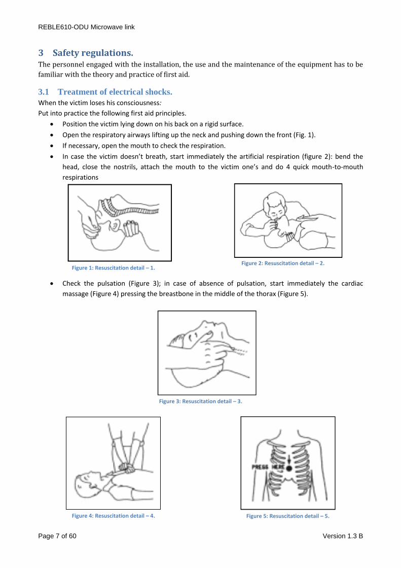
3.1 Treatment of electrical shocks.
When the victim loses his consciousness:
Put into practice the following first aid principles.
Position the victim lying down on his back on a rigid surface.
Open the respiratory airways lifting up the neck and pushing down the front (Fig. 1).
If necessary, open the mouth to check the respiration.
In case the victim doesn’t breath, start immediately the artificial respiration (figure 2): bend the
head, close the nostrils, attach the mouth to the victim one’s and do 4 quick mouth-to-mouth
respirations
Figure 1: Resuscitation detail – 1.
Figure 2: Resuscitation detail – 2.
Check the pulsation (Figure 3); in case of absence of pulsation, start immediately the cardiac
massage (Figure 4) pressing the breastbone in the middle of the thorax (Figure 5).
Figure 3: Resuscitation detail – 3.
Figure 4: Resuscitation detail – 4.
Figure 5: Resuscitation detail – 5.

REBLE610 Microwave link
Page 8 of 60 Version 1.3 B
When there is only one rescuer, he has to maintain a rhythm of 15 compressions alternated with 2
quick respirations.
In case there are two rescuers, the rhythm should be one respiration each 5 compressions.
Do not interrupt the cardiac massage during the artificial breathing
Call a doctor as soon as possible
When the victim is conscious
Cover up the victim with a blanket.
Try to calm down the victim.
Unbutton the cloche and lay down the victim.
Call a doctor as soon as possible.
3.2 Treatment of electrical burns.
Large burns and cuts of the skin
Cover up the interested area with a clean sheet or cloth.
Do not open the blisters; remove the fabric and the parts of the clothes attached to the skin; apply
a suitable ointment.
Treat the victim according to the type of accident.
Take the victim to the hospital as soon as possible.
When the arms and legs are affected keep them raised.
When there is no doctor available within an hour and the victim is conscious and does not retch, give a
liquid solution containing salt and sodium bicarbonate: 1 teaspoon of salt and half a teaspoon of sodium
bicarbonate for each 250 ml of water.
Have the victim sip half a glass of the solution for four times and for 15 minutes.
Stop when retching.
Do not give any alcoholics
Less serious burns
Apply cold (not frozen) gauzes using a clean as possible cloth.
Do not open the blisters; remove the fabric and the parts of the clothes attached to the skin; apply
a suitable ointment.
When necessary, put on clean and dry clothes.
Treat the victim according to the type of accident.
Take the victim to the hospital as soon as possible.
When the arms and legs are affected keep them raised.
4 General Description.
The REBLE610-ODU is the outdoor version of the REBLE610, from which it differs for the separation
between the RF part (located in a waterproof aluminum case) from the modem,
the I/O section and control.
The indoor unit or control unit (REBLE610-IDU) belongs to the same chassis of the REBLE610, which makes
for a more efficient maintenance and an easier frequency modification which is always a difficult task; As
for its predecessor, there is a hot-swappable redundant power supply, available both in AC and DC.
REBLE610-ODU Microwave link
Page 9 of 60 Version 1.3 B
The modular approach has brought to the development of the data interface module (containing
modulator, demodulator and data interface) and the RF module (containing Transmitter, Receiver and
channel filter). From an RF point of view the new transmission circuitry is able to guarantee at least 1 watt
at the head with every modulation scheme, introducing in addition, wideband precorrection (up to 1GHz
depending on frequency band). Data interface is equipped with 5 SMPTE310/ASI/BTS ports on BNC
connectors, configurable as input or output; this feature let have in a single chassis the functions of a
SMPTE310/ASI matrix and a SMPTE310/ASI distributor, both in input and output. The link let also transfer
IP traffic on a GbE port, 5 E1 2.048 Kbps signal and a “transit” connection (just not to use too many coaxial
cables for the transit).
To transfer all these signals the channel capacity has been increased to 56MHz and bitrate equal to
310Mbit/s; using an optional XPIC module (and an extra Reble610) it is possible to duplicate the bitrate
increasing it to 610MBit/s, exploiting H and V polarizations and cancelling undesired content using special
algorithms. A new management software offers complete control over device parameters and settings, an
on-board TFT touch-screen allows for a simple and intuitive user interface to check for anomalies. The
same monitoring and control can be carried out thru a particularly easy to use web interface and thru
SNMP.
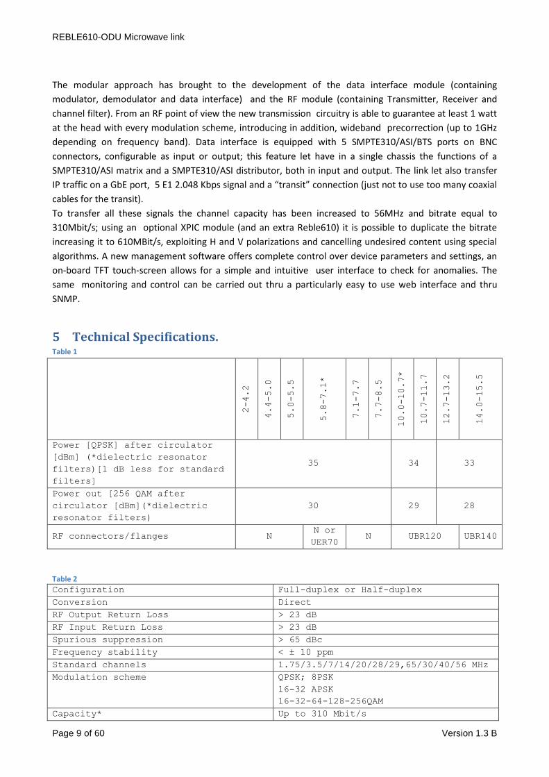
5 Technical Specifications. Table 1
2-4.2
4.4-5.0
5.0-5.5
5.8-7.1*
7.1-7.7
7.7-8.5
10.0-10.7*
10.7-11.7
12.7-13.2
14.0-15.5
Power [QPSK] after circulator
[dBm] (*dielectric resonator
filters)[1 dB less for standard
filters]
35 34 33
Power out [256 QAM after
circulator [dBm](*dielectric
resonator filters)
30 29 28
RF connectors/flanges N N or
UER70 N UBR120 UBR140
Table 2
Configuration Full-duplex or Half-duplex
Conversion Direct
RF Output Return Loss > 23 dB
RF Input Return Loss > 23 dB
Spurious suppression > 65 dBc
Frequency stability < ± 10 ppm
Standard channels 1.75/3.5/7/14/20/28/29,65/30/40/56 MHz
Modulation scheme QPSK; 8PSK
16-32 APSK
16-32-64-128-256QAM
Capacity* Up to 310 Mbit/s
REBLE610-ODU Microwave link
Page 10 of 60 Version 1.3 B
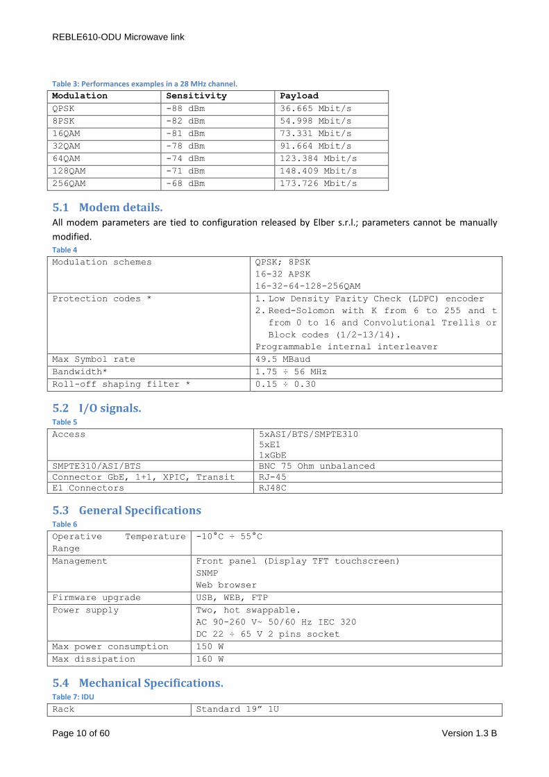
Table 3: Performances examples in a 28 MHz channel.
Modulation Sensitivity Payload
QPSK -88 dBm 36.665 Mbit/s
8PSK -82 dBm 54.998 Mbit/s
16QAM -81 dBm 73.331 Mbit/s
32QAM -78 dBm 91.664 Mbit/s
64QAM -74 dBm 123.384 Mbit/s
128QAM -71 dBm 148.409 Mbit/s
256QAM -68 dBm 173.726 Mbit/s
5.1 Modem details. All modem parameters are tied to configuration released by Elber s.r.l.; parameters cannot be manually
modified. Table 4
Modulation schemes QPSK; 8PSK
16-32 APSK
16-32-64-128-256QAM
Protection codes * 1. Low Density Parity Check (LDPC) encoder
2. Reed-Solomon with K from 6 to 255 and t
from 0 to 16 and Convolutional Trellis or
Block codes (1/2-13/14).
Programmable internal interleaver
Max Symbol rate 49.5 MBaud
Bandwidth* 1.75 ÷ 56 MHz
Roll-off shaping filter * 0.15 ÷ 0.30
5.2 I/O signals. Table 5
Access 5xASI/BTS/SMPTE310
5xE1
1xGbE
SMPTE310/ASI/BTS BNC 75 Ohm unbalanced
Connector GbE, 1+1, XPIC, Transit RJ-45
E1 Connectors RJ48C
5.3 General Specifications Table 6
Operative Temperature
Range
-10°C ÷ 55°C
Management Front panel (Display TFT touchscreen)
SNMP
Web browser
Firmware upgrade USB, WEB, FTP
Power supply Two, hot swappable.
AC 90-260 V~ 50/60 Hz IEC 320
DC 22 ÷ 65 V 2 pins socket
Max power consumption 150 W
Max dissipation 160 W
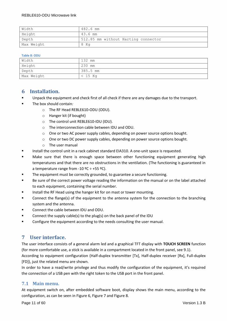
5.4 Mechanical Specifications. Table 7: IDU
Rack Standard 19” 1U
REBLE610-ODU Microwave link
Page 11 of 60 Version 1.3 B
Width 482.6 mm
Height 43.6 mm
Depth 512.85 mm without Harting connector
Max Weight 8 Kg
Table 8: ODU
Width 132 mm
Height 230 mm
Depth 385.5 mm
Max Weight < 15 Kg
6 Installation. Unpack the equipment and check first of all check if there are any damages due to the transport.
The box should contain:
o The RF Head REBLE610-ODU (ODU).
o Hanger kit (if bought)
o The control unit REBLE610-IDU (IDU).
o The interconnection cable between IDU and ODU.
o One or two AC power supply cables, depending on power source options bought.
o One or two DC power supply cables, depending on power source options bought.
o The user manual
Install the control unit in a rack cabinet standard EIA310. A one-unit space is requested.
Make sure that there is enough space between other functioning equipment generating high
temperatures and that there are no obstructions in the ventilation. (The functioning is guaranteed in
a temperature range from -10 ºC ÷ +55 ºC).
The equipment must be correctly grounded, to guarantee a secure functioning.
Be sure of the correct power voltage reading the information on the manual or on the label attached
to each equipment, containing the serial number.
Install the RF Head using the hanger kit for on mast or tower mounting.
Connect the flange(s) of the equipment to the antenna system for the connection to the branching
system and the antenna.
Connect the cable between IDU and ODU.
Connect the supply cable(s) to the plug(s) on the back panel of the IDU
Configure the equipment according to the needs consulting the user manual.
7 User interface. The user interface consists of a general alarm led and a graphical TFT display with TOUCH SCREEN function
(for more comfortable use, a stick is available in a compartment located in the front panel, see 9.1).
According to equipment configuration (Half-duplex transmitter [Tx], Half-duplex receiver [Rx], Full-duplex
[FD]), just the related menu are shown.
In order to have a read/write privilege and thus modify the configuration of the equipment, it’s required
the connection of a USB pen with the right token to the USB port in the front panel.
7.1 Main menu. At equipment switch on, after embedded software boot, display shows the main menu, according to the
configuration, as can be seen in Figure 6, Figure 7 and Figure 8.
REBLE610-ODU Microwave link
Page 12 of 60 Version 1.3 B
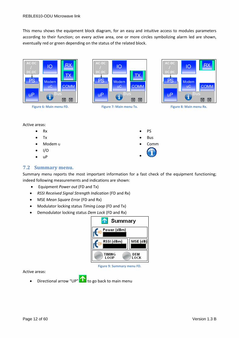
This menu shows the equipment block diagram, for an easy and intuitive access to modules parameters
according to their function; on every active area, one or more circles symbolizing alarm led are shown,
eventually red or green depending on the status of the related block.
Figure 6: Main menu FD.
Figure 7: Main menu Tx.
Figure 8: Main menu Rx.
Active areas:
Rx
Tx
Modem uC
I/O
uP
PS
Bus
Comm
7.2 Summary menu. Summary menu reports the most important information for a fast check of the equipment functioning;
indeed following measurements and indications are shown:
Equipment Power out (FD and Tx)
RSSI Received Signal Strength Indication (FD and Rx)
MSE Mean Square Error (FD and Rx)
Modulator locking status Timing Loop (FD and Tx)
Demodulator locking status Dem Lock (FD and Rx)
Figure 9: Summary menu FD.
Active areas:
Directional arrow “UP” to go back to main menu
REBLE610-ODU Microwave link
Page 13 of 60 Version 1.3 B
7.3 Menu uProcessor (uP).
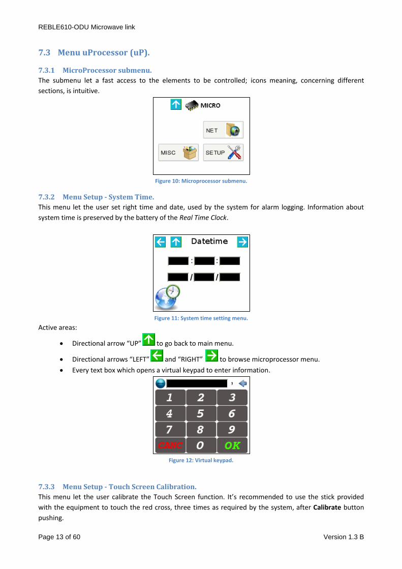
7.3.1 MicroProcessor submenu.
The submenu let a fast access to the elements to be controlled; icons meaning, concerning different
sections, is intuitive.
Figure 10: Microprocessor submenu.
7.3.2 Menu Setup - System Time.
This menu let the user set right time and date, used by the system for alarm logging. Information about
system time is preserved by the battery of the Real Time Clock.
Figure 11: System time setting menu.
Active areas:
Directional arrow “UP” to go back to main menu.
Directional arrows “LEFT” and “RIGHT” to browse microprocessor menu.
Every text box which opens a virtual keypad to enter information.
Figure 12: Virtual keypad.
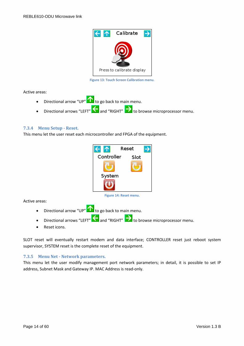
7.3.3 Menu Setup - Touch Screen Calibration.
This menu let the user calibrate the Touch Screen function. It’s recommended to use the stick provided
with the equipment to touch the red cross, three times as required by the system, after Calibrate button
pushing.
REBLE610-ODU Microwave link
Page 14 of 60 Version 1.3 B
Figure 13: Touch Screen Calibration menu.
Active areas:
Directional arrow “UP” to go back to main menu.
Directional arrows “LEFT” and “RIGHT” to browse microprocessor menu.
7.3.4 Menu Setup - Reset.
This menu let the user reset each microcontroller and FPGA of the equipment.
Figure 14: Reset menu.
Active areas:
Directional arrow “UP” to go back to main menu.
Directional arrows “LEFT” and “RIGHT” to browse microprocessor menu.
Reset icons.
SLOT reset will eventually restart modem and data interface; CONTROLLER reset just reboot system
supervisor, SYSTEM reset is the complete reset of the equipment.
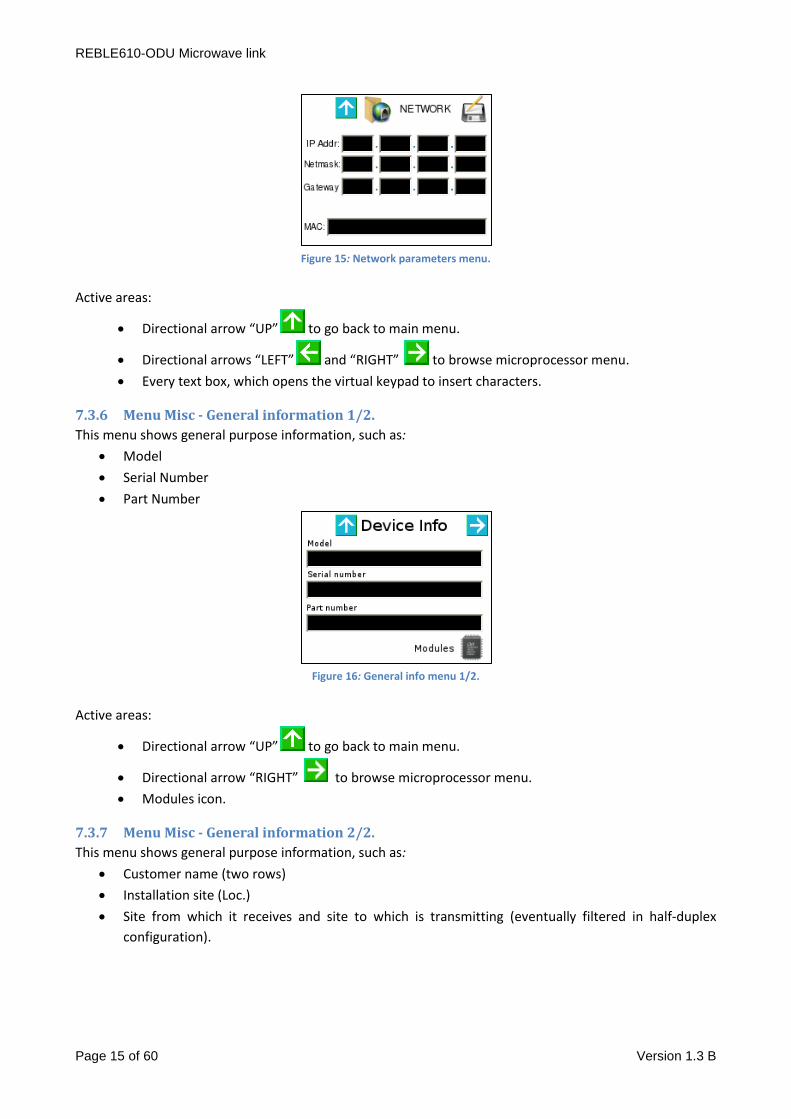
7.3.5 Menu Net - Network parameters.
This menu let the user modify management port network parameters; in detail, it is possible to set IP
address, Subnet Mask and Gateway IP. MAC Address is read-only.
REBLE610-ODU Microwave link
Page 15 of 60 Version 1.3 B
Figure 15: Network parameters menu.
Active areas:
Directional arrow “UP” to go back to main menu.
Directional arrows “LEFT” and “RIGHT” to browse microprocessor menu.
Every text box, which opens the virtual keypad to insert characters.
7.3.6 Menu Misc - General information 1/2.
This menu shows general purpose information, such as:
Model
Serial Number
Part Number
Figure 16: General info menu 1/2.
Active areas:
Directional arrow “UP” to go back to main menu.
Directional arrow “RIGHT” to browse microprocessor menu.
Modules icon.
7.3.7 Menu Misc - General information 2/2.
This menu shows general purpose information, such as:
Customer name (two rows)
Installation site (Loc.)
Site from which it receives and site to which is transmitting (eventually filtered in half-duplex
configuration).

REBLE610-ODU Microwave link
Page 16 of 60 Version 1.3 B
Figure 17: General info menu 2/2.
Active areas:
Directional arrow “UP” to go back to main menu.
Directional arrows “LEFT” and “RIGHT” to browse microprocessor menu.
7.3.8 Menu Misc - Modules.
7.3.8.1 Menu Misc - Modules - Controller.
This menu shows controller general purpose information such as:
Model
Version
Revision
Figure 18: General purpose information controller.
Active areas:
Directional arrow “UP” to go back to main menu.
Directional arrows “LEFT” and “RIGHT” to browse microprocessor menu.
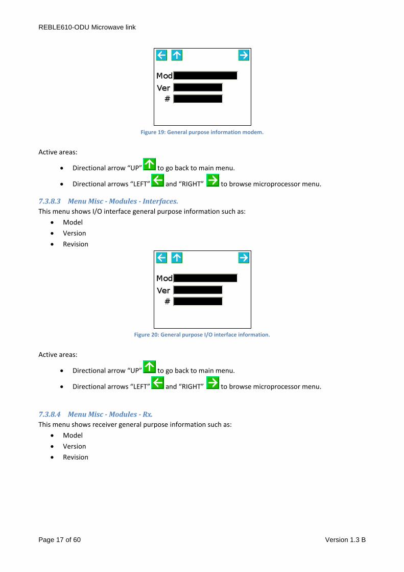
7.3.8.2 Menu Misc - Modules - Modem.
This menu shows modem general purpose information such as:
Model
Version
Revision
REBLE610-ODU Microwave link
Page 17 of 60 Version 1.3 B
Figure 19: General purpose information modem.
Active areas:
Directional arrow “UP” to go back to main menu.
Directional arrows “LEFT” and “RIGHT” to browse microprocessor menu.
7.3.8.3 Menu Misc - Modules - Interfaces.
This menu shows I/O interface general purpose information such as:
Model
Version
Revision
Figure 20: General purpose I/O interface information.
Active areas:
Directional arrow “UP” to go back to main menu.
Directional arrows “LEFT” and “RIGHT” to browse microprocessor menu.
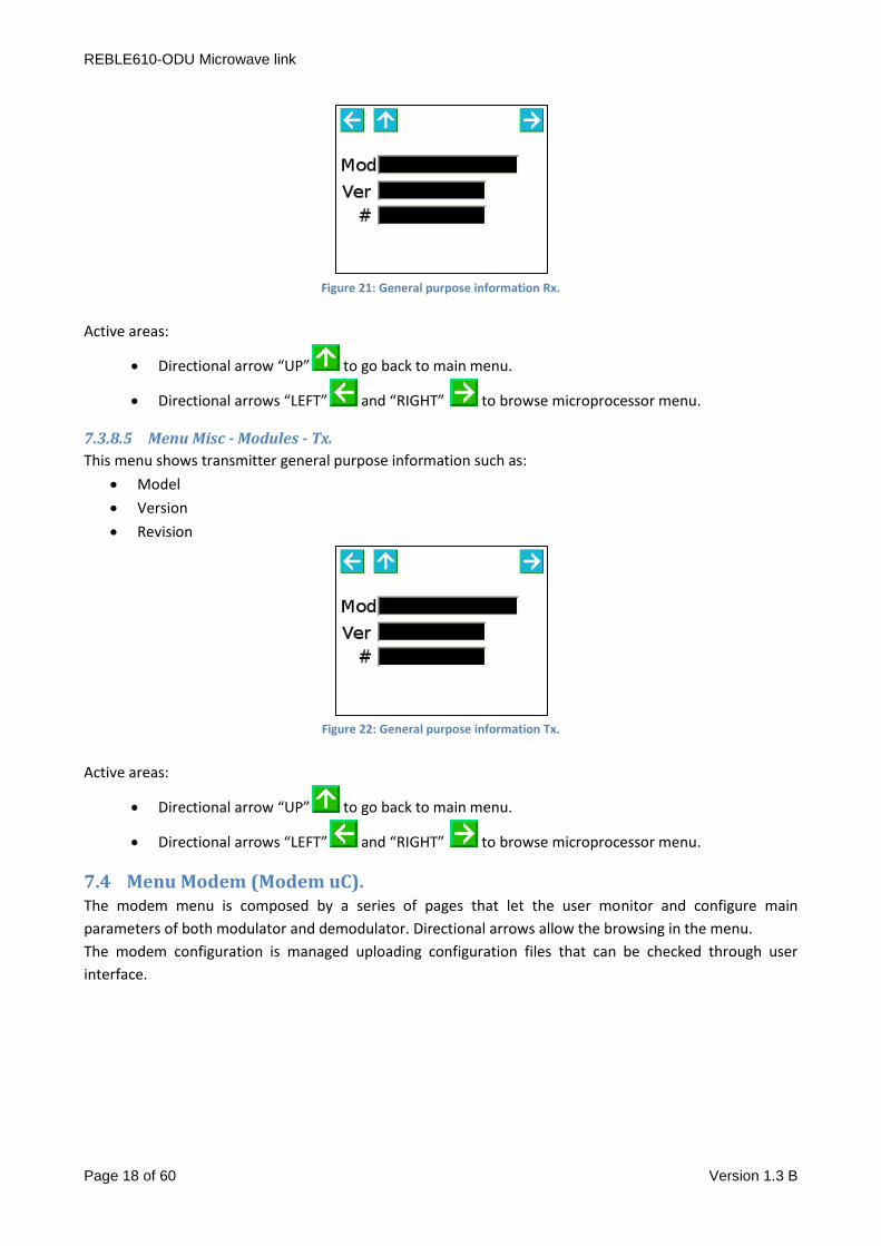
7.3.8.4 Menu Misc - Modules - Rx.
This menu shows receiver general purpose information such as:
Model
Version
Revision
REBLE610-ODU Microwave link
Page 18 of 60 Version 1.3 B
Figure 21: General purpose information Rx.
Active areas:
Directional arrow “UP” to go back to main menu.
Directional arrows “LEFT” and “RIGHT” to browse microprocessor menu.
7.3.8.5 Menu Misc - Modules - Tx.
This menu shows transmitter general purpose information such as:
Model
Version
Revision
Figure 22: General purpose information Tx.
Active areas:
Directional arrow “UP” to go back to main menu.
Directional arrows “LEFT” and “RIGHT” to browse microprocessor menu.
7.4 Menu Modem (Modem uC). The modem menu is composed by a series of pages that let the user monitor and configure main
parameters of both modulator and demodulator. Directional arrows allow the browsing in the menu.
The modem configuration is managed uploading configuration files that can be checked through user
interface.
REBLE610-ODU Microwave link
Page 19 of 60 Version 1.3 B
7.4.1 Modem submenu.
The submenu let a fast access to the elements to be controlled; icons meaning, concerning different
sections, is intuitive.
Figure 23: Modem submenu.
Active areas:
Directional arrow “UP” to go back to main menu.
Icons
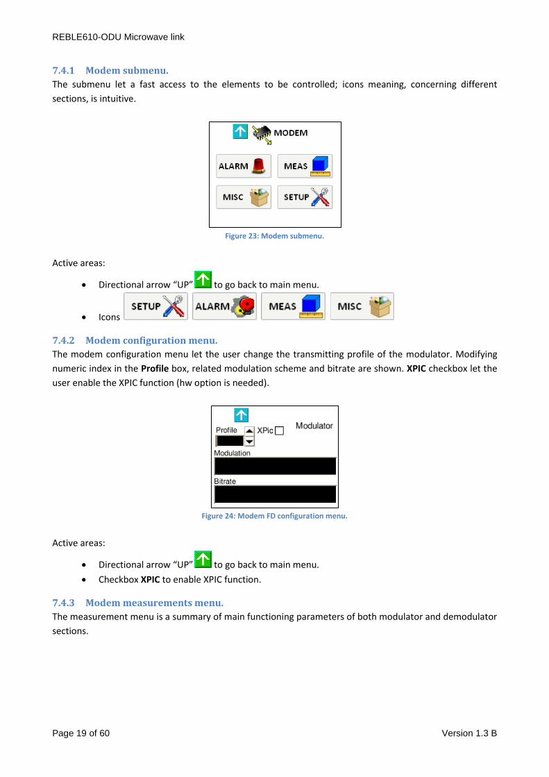
7.4.2 Modem configuration menu.
The modem configuration menu let the user change the transmitting profile of the modulator. Modifying
numeric index in the Profile box, related modulation scheme and bitrate are shown. XPIC checkbox let the
user enable the XPIC function (hw option is needed).
Figure 24: Modem FD configuration menu.
Active areas:
Directional arrow “UP” to go back to main menu.
Checkbox XPIC to enable XPIC function.
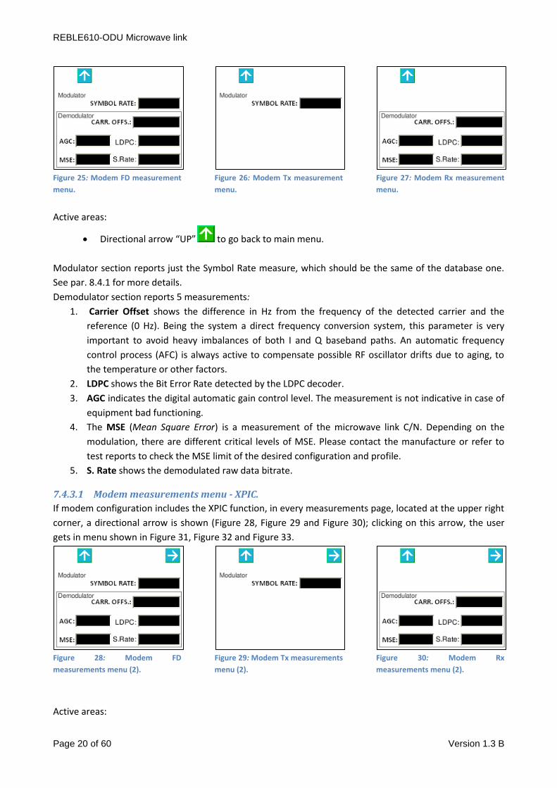
7.4.3 Modem measurements menu.
The measurement menu is a summary of main functioning parameters of both modulator and demodulator
sections.
REBLE610-ODU Microwave link
Page 20 of 60 Version 1.3 B
Figure 25: Modem FD measurement
menu.
Figure 26: Modem Tx measurement
menu.
Figure 27: Modem Rx measurement
menu.
Active areas:
Directional arrow “UP” to go back to main menu.
Modulator section reports just the Symbol Rate measure, which should be the same of the database one.
See par. 8.4.1 for more details.
Demodulator section reports 5 measurements:
1. Carrier Offset shows the difference in Hz from the frequency of the detected carrier and the
reference (0 Hz). Being the system a direct frequency conversion system, this parameter is very
important to avoid heavy imbalances of both I and Q baseband paths. An automatic frequency
control process (AFC) is always active to compensate possible RF oscillator drifts due to aging, to
the temperature or other factors.
2. LDPC shows the Bit Error Rate detected by the LDPC decoder.
3. AGC indicates the digital automatic gain control level. The measurement is not indicative in case of
equipment bad functioning.
4. The MSE (Mean Square Error) is a measurement of the microwave link C/N. Depending on the
modulation, there are different critical levels of MSE. Please contact the manufacture or refer to
test reports to check the MSE limit of the desired configuration and profile.
5. S. Rate shows the demodulated raw data bitrate.
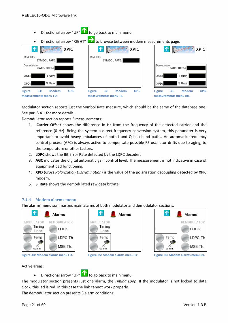
7.4.3.1 Modem measurements menu - XPIC.
If modem configuration includes the XPIC function, in every measurements page, located at the upper right
corner, a directional arrow is shown (Figure 28, Figure 29 and Figure 30); clicking on this arrow, the user
gets in menu shown in Figure 31, Figure 32 and Figure 33.
Figure 28: Modem FD
measurements menu (2).
Figure 29: Modem Tx measurements
menu (2).
Figure 30: Modem Rx
measurements menu (2).
Active areas:
REBLE610-ODU Microwave link
Page 21 of 60 Version 1.3 B
Directional arrow “UP” to go back to main menu.
Directional arrow “RIGHT” to browse between modem measurements page.
Figure 31: Modem XPIC
measurements menu FD.
Figure 32: Modem XPIC
measurements menu Tx.
Figure 33: Modem XPIC
measurements menu Rx.
Modulator section reports just the Symbol Rate measure, which should be the same of the database one.
See par. 8.4.1 for more details.
Demodulator section reports 5 measurements:
1. Carrier Offset shows the difference in Hz from the frequency of the detected carrier and the
reference (0 Hz). Being the system a direct frequency conversion system, this parameter is very
important to avoid heavy imbalances of both I and Q baseband paths. An automatic frequency
control process (AFC) is always active to compensate possible RF oscillator drifts due to aging, to
the temperature or other factors.
2. LDPC shows the Bit Error Rate detected by the LDPC decoder.
3. AGC indicates the digital automatic gain control level. The measurement is not indicative in case of
equipment bad functioning.
4. XPD (Cross Polarization Discrimination) is the value of the polarization decoupling detected by XPIC
modem.
5. S. Rate shows the demodulated raw data bitrate.
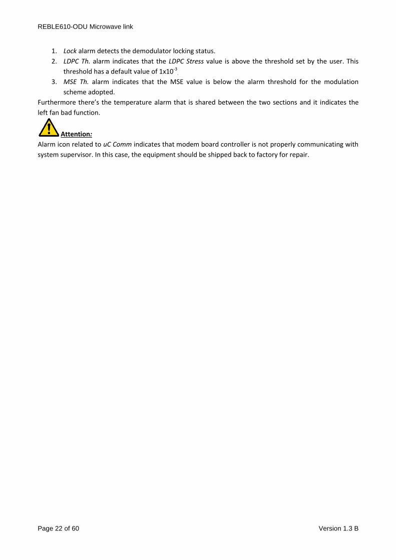
7.4.4 Modem alarms menu.
The alarms menu summarizes main alarms of both modulator and demodulator sections.
Figure 34: Modem alarms menu FD.
Figure 35: Modem alarms menu Tx.
Figure 36: Modem alarms menu Rx.
Active areas:
Directional arrow “UP” to go back to main menu.
The modulator section presents just one alarm, the Timing Loop. If the modulator is not locked to data
clock, this led is red. In this case the link cannot work properly.
The demodulator section presents 3 alarm conditions:
REBLE610-ODU Microwave link
Page 22 of 60 Version 1.3 B
1. Lock alarm detects the demodulator locking status.
2. LDPC Th. alarm indicates that the LDPC Stress value is above the threshold set by the user. This
threshold has a default value of 1x10⁻³.
3. MSE Th. alarm indicates that the MSE value is below the alarm threshold for the modulation
scheme adopted.
Furthermore there’s the temperature alarm that is shared between the two sections and it indicates the
left fan bad function.
Attention:
Alarm icon related to uC Comm indicates that modem board controller is not properly communicating with
system supervisor. In this case, the equipment should be shipped back to factory for repair.
REBLE610-ODU Microwave link
Page 23 of 60 Version 1.3 B
7.4.5 Modem general menu.
Modem general menu reports details of demodulator profile and configuration (the demodulator
automatically lock on the profile). Just modulation scheme, occupied bandwidth and net bitrate are shown,
but for further information the related section of the web interface can be seen.
Moreover it is possible to enable the internal Clean Carrier generator (One tone checkbox), the two tones
generator (Two Tone) and the predistorsion (Predistorsion); by default, Normal and Predistorsion
checkbox are enabled.
Figure 37: Modem general menu FD.
Figure 38: Modem general menu Tx.
Figure 39: Modem general menu Rx.
Active areas:
Directional arrow “UP” to go back to main menu.
Checkbox Normal for normal functioning.
Checkbox Single tone to enable Clean Carrier generator (link frequency + 10 MHz); this setting
isn’t stored, so it is to be enabled again in case of system restart.
Checkbox Two tone to enable the two tone test signal; this setting isn’t stored, so it is to be
enabled again in case of system restart.
Checkbox Predistorsion to enable the non-linear precorrection of the amplifier; depending on
the frequency of operation, the system load the calibration curve stored in factory.
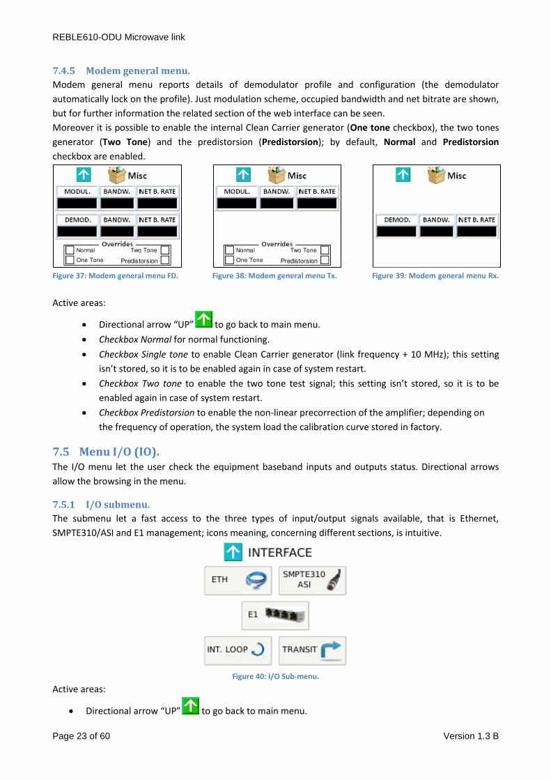
7.5 Menu I/O (IO). The I/O menu let the user check the equipment baseband inputs and outputs status. Directional arrows
allow the browsing in the menu.
7.5.1 I/O submenu.
The submenu let a fast access to the three types of input/output signals available, that is Ethernet,
SMPTE310/ASI and E1 management; icons meaning, concerning different sections, is intuitive.
Figure 40: I/O Sub-menu.
Active areas:
Directional arrow “UP” to go back to main menu.
REBLE610-ODU Microwave link
Page 24 of 60 Version 1.3 B
Icons .
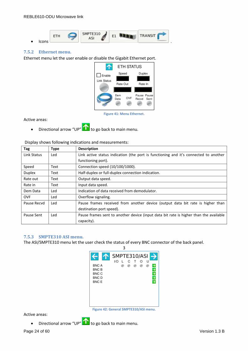
7.5.2 Ethernet menu.
Ethernet menu let the user enable or disable the Gigabit Ethernet port.
Figure 41: Menu Ethernet.
Active areas:
Directional arrow “UP” to go back to main menu.
Display shows following indications and measurements:
Tag Type Description
Link Status Led Link active status indication (the port is functioning and it’s connected to another
functioning port).
Speed Text Connection speed (10/100/1000).
Duplex Text Half-duplex or full-duplex connection indication.
Rate out Text Output data speed.
Rate in Text Input data speed.
Dem Data Led Indication of data received from demodulator.
OVF Led Overflow signaling.
Pause Recvd Led Pause frames received from another device (output data bit rate is higher than
destination port speed).
Pause Sent Led Pause frames sent to another device (input data bit rate is higher than the available
capacity).
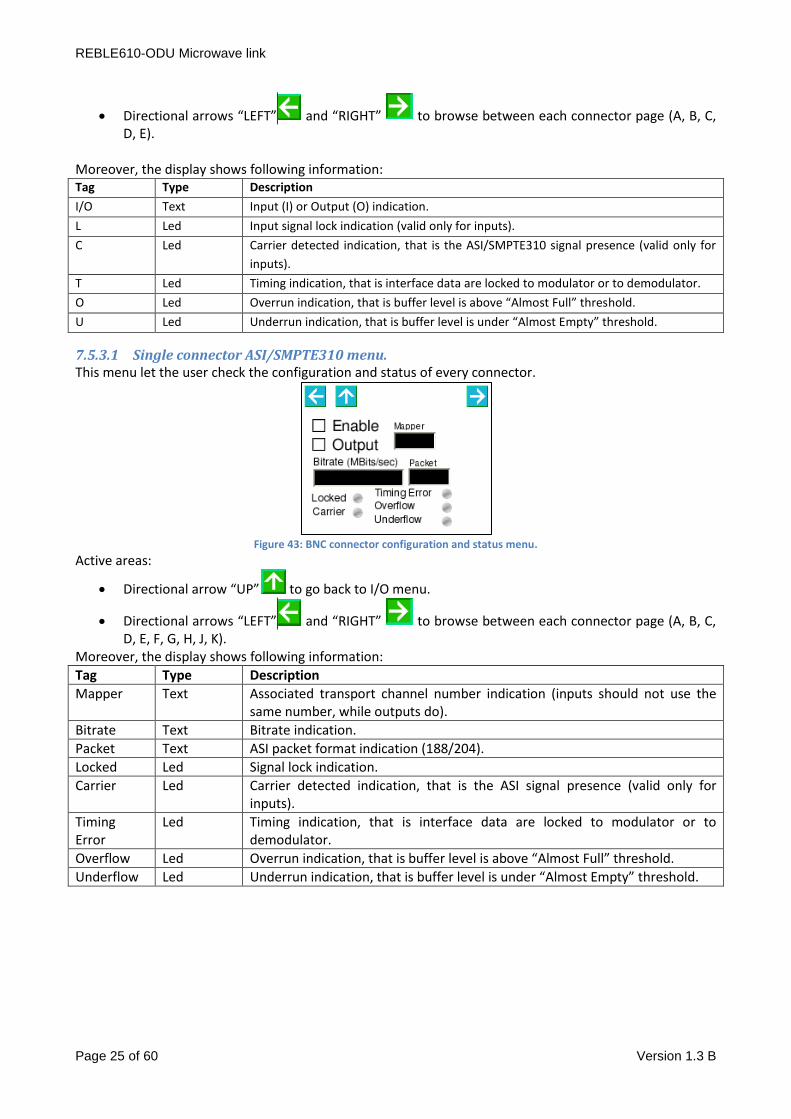
7.5.3 SMPTE310 ASI menu. The ASI/SMPTE310 menu let the user check the status of every BNC connector of the back panel.
3
Figure 42: General SMPTE310/ASI menu.
Active areas:
Directional arrow “UP” to go back to main menu.
REBLE610-ODU Microwave link
Page 25 of 60 Version 1.3 B
Directional arrows “LEFT” and “RIGHT” to browse between each connector page (A, B, C, D, E).
Moreover, the display shows following information: Tag Type Description
I/O Text Input (I) or Output (O) indication.
L Led Input signal lock indication (valid only for inputs).
C Led Carrier detected indication, that is the ASI/SMPTE310 signal presence (valid only for
inputs).
T Led Timing indication, that is interface data are locked to modulator or to demodulator.
O Led Overrun indication, that is buffer level is above “Almost Full” threshold.
U Led Underrun indication, that is buffer level is under “Almost Empty” threshold.
7.5.3.1 Single connector ASI/SMPTE310 menu. This menu let the user check the configuration and status of every connector.
Figure 43: BNC connector configuration and status menu.
Active areas:
Directional arrow “UP” to go back to I/O menu.
Directional arrows “LEFT” and “RIGHT” to browse between each connector page (A, B, C, D, E, F, G, H, J, K).
Moreover, the display shows following information:
Tag Type Description
Mapper Text Associated transport channel number indication (inputs should not use the same number, while outputs do).
Bitrate Text Bitrate indication.
Packet Text ASI packet format indication (188/204).
Locked Led Signal lock indication.
Carrier Led Carrier detected indication, that is the ASI signal presence (valid only for inputs).
Timing Error
Led Timing indication, that is interface data are locked to modulator or to demodulator.
Overflow Led Overrun indication, that is buffer level is above “Almost Full” threshold.
Underflow Led Underrun indication, that is buffer level is under “Almost Empty” threshold.

REBLE610-ODU Microwave link
Page 26 of 60 Version 1.3 B
7.5.4 E1 menu.
Figure 44: General E1 Ports
Tag Type Description
I/O Text Input (I) or Output (O) indication.
L Led Input signal lock indication (valid only for inputs).
C Led Carrier detected indication, that is the E1 signal presence (valid only for inputs).
T Led Timing indication, that is interface data are locked to modulator or to demodulator.
O Led Overrun indication, that is buffer level is above “Almost Full” threshold.
U Led Underrun indication, that is buffer level is under “Almost Empty” threshold.
7.5.4.1 Single connector E1 menu.
Figure 45: RJ48C connector configuration and status menu.
Active areas:
Directional arrow “UP” to go back to I/O menu.
Directional arrows “LEFT” and “RIGHT” to browse between each connector page (A, B, C, D, E, F, G, H, J, K).
Moreover, the display shows following information:
Tag Type Description
Mapper Text Associated transport channel number indication (inputs should not use the same number, while outputs do).
Bitrate Text Bitrate indication.
Packet Text Unused.
Locked Led Signal lock indication.
Carrier Led Carrier detected indication, that is the E1 signal presence (valid only for inputs).
Timing Error
Led Timing indication, that is interface data are locked to modulator or to demodulator.
Overflow Led Overrun indication, that is buffer level is above “Almost Full” threshold.
Underflow Led Underrun indication, that is buffer level is under “Almost Empty” threshold.
REBLE610-ODU Microwave link
Page 27 of 60 Version 1.3 B
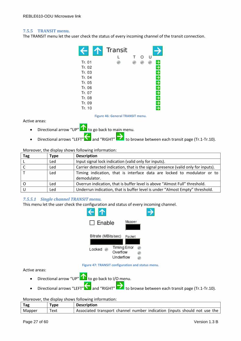
7.5.5 TRANSIT menu. The TRANSIT menu let the user check the status of every incoming channel of the transit connection.
Figure 46: General TRANSIT menu.
Active areas:
Directional arrow “UP” to go back to main menu.
Directional arrows “LEFT” and “RIGHT” to browse between each transit page (Tr.1-Tr.10). Moreover, the display shows following information:
Tag Type Description
L Led Input signal lock indication (valid only for inputs).
C Led Carrier detected indication, that is the signal presence (valid only for inputs).
T Led Timing indication, that is interface data are locked to modulator or to demodulator.
O Led Overrun indication, that is buffer level is above “Almost Full” threshold.
U Led Underrun indication, that is buffer level is under “Almost Empty” threshold.
7.5.5.1 Single channel TRANSIT menu. This menu let the user check the configuration and status of every incoming channel.
Figure 47: TRANSIT configuration and status menu.
Active areas:
Directional arrow “UP” to go back to I/O menu.
Directional arrows “LEFT” and “RIGHT” to browse between each transit page (Tr.1-Tr.10). Moreover, the display shows following information:
Tag Type Description
Mapper Text Associated transport channel number indication (inputs should not use the

REBLE610-ODU Microwave link
Page 28 of 60 Version 1.3 B
same number, while outputs do).
Bitrate Text Bitrate indication.
Packet Text ASI packet format indication (188/204).
Locked Led Signal lock indication.
Carrier Led Carrier detected indication, that is the ASI signal presence (valid only for inputs).
Timing Error
Led Timing indication, that is interface data are locked to modulator or to demodulator.
Overflow Led Overrun indication, that is buffer level is above “Almost Full” threshold.
Underflow Led Underrun indication, that is buffer level is under “Almost Empty” threshold.
7.6 Menu Transmitter (TX). The Transmitter menu consists of a single page that allows monitoring and setting of the most important
parameters of the transmitter module; the menu is accessible only for FD or Tx devices.
Figure 48: Transmitter menu.
Active areas:
Directional arrow “UP” to go back to main menu.
Checkbox for the squelch of the transmitter.
The page also shows three icons that correspond to the alarm led:
1. An alarm for the oscillator status (in case of oscillator unlock, the transmitter is silenced through
hardware pin).
2. An alarm indicating low power at the transmitter output.
3. An alarm indicating that the temperature of the module is higher than 60°C.
Moreover, the page reports temperature and power output measurements.
7.7 Menu Receiver (RX). The Receiver menu consists of a single page that allows monitoring and setting of the most important
parameters of the receiver module; the menu is accessible only for FD or Rx devices.

REBLE610-ODU Microwave link
Page 29 of 60 Version 1.3 B
Figure 49: Receiver menu.
Active areas:
Directional arrow “UP” to go back to main menu.
The page also shows three icons that correspond to the alarm led:
1. An alarm for the oscillator status
2. An alarm indicating the low field level received for the used modulation.
3. An alarm indicating that the temperature of the module is higher than 55°C.
The page reports as well the measurements of the registered temperature and received field level (RSSI).
7.8 Menu Communicator.
7.8.1 Communicator submenu.
This menu helps the user monitor and configure the boards managing the communication between IDU and
ODU, which are the COMM_UNIT, and the STEP-UP and STEP-DOWN supplies.
Clicking on icon, Figure 50 menu appears.
Figure 50: Menu Comm link.
Active areas:
Self-explaining icons , , and to access to related submenu.
Arrow to go back to previous menu.
7.8.2 Menu Status Communicator.
User may accede to this menu by clicking on , and following submenu opens:
REBLE610-ODU Microwave link
Page 30 of 60 Version 1.3 B
Figure 51: Menu status communicator.
Active areas:
Arrow to go back to previous menu.
Tag Description
Local BER BER indication of IDU communication board.
Remote BER BER indication of ODU communication board.
Temp FPGA Temperature indication of IDU communication board.
Temp Step Up Temperature indication of voltage step-up board for ODU interconnection.
V (48V) Step-up output voltage indication.
Current Step-up current consumption indication.
V Step-up input voltage indication.
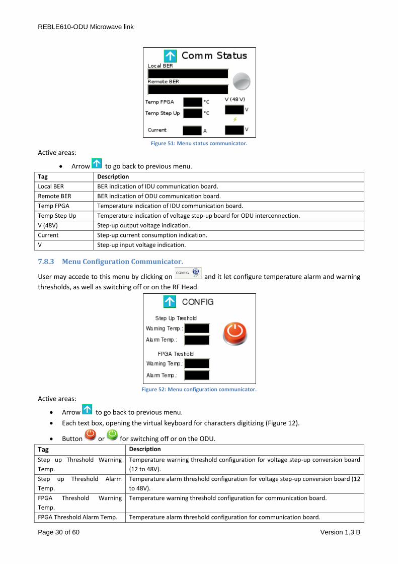
7.8.3 Menu Configuration Communicator.
User may accede to this menu by clicking on and it let configure temperature alarm and warning
thresholds, as well as switching off or on the RF Head.
Figure 52: Menu configuration communicator.
Active areas:
Arrow to go back to previous menu.
Each text box, opening the virtual keyboard for characters digitizing (Figure 12).
Button or for switching off or on the ODU.
Tag Description
Step up Threshold Warning
Temp.
Temperature warning threshold configuration for voltage step-up conversion board
(12 to 48V).
Step up Threshold Alarm
Temp.
Temperature alarm threshold configuration for voltage step-up conversion board (12
to 48V).
FPGA Threshold Warning
Temp.
Temperature warning threshold configuration for communication board.
FPGA Threshold Alarm Temp. Temperature alarm threshold configuration for communication board.
REBLE610-ODU Microwave link
Page 31 of 60 Version 1.3 B
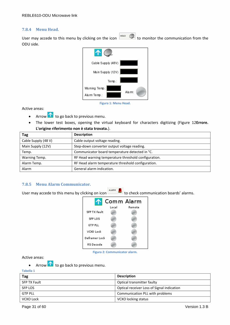
7.8.4 Menu Head.
User may accede to this menu by clicking on the icon to monitor the communication from the
ODU side.
Figura 1: Menu Head.
Active areas:
Arrow to go back to previous menu.
The lower test boxes, opening the virtual keyboard for characters digitizing (Figure 12Errore.
L'origine riferimento non è stata trovata.).
Tag Description
Cable Supply (48 V) Cable output voltage reading.
Main Supply (12V) Step-down converter output voltage reading.
Temp. Communicator board temperature detected in °C.
Warning Temp. RF Head warning temperature threshold configuration.
Alarm Temp. RF Head alarm temperature threshold configuration.
Alarm General alarm indication.
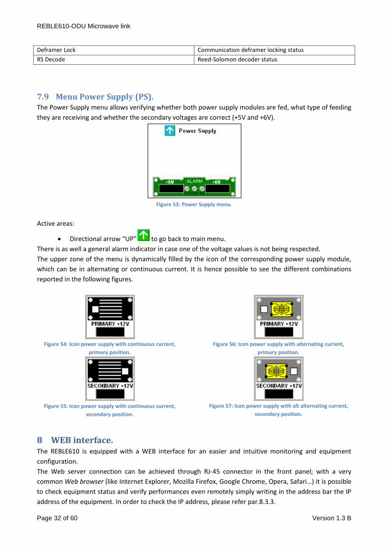
7.8.5 Menu Alarm Communicator.
User may accede to this menu by clicking on icon to check communication boards’ alarms.
Figura 2: Communicator alarm.
Active areas:
Arrow to go back to previous menu. Tabella 1
Tag Description
SFP TX Fault Optical transmitter faulty
SFP LOS Optical receiver Loss of Signal indication
GTP PLL Communication PLL with problems
VCXO Lock VCXO locking status
REBLE610-ODU Microwave link
Page 32 of 60 Version 1.3 B
Deframer Lock Communication deframer locking status
RS Decode Reed-Solomon decoder status
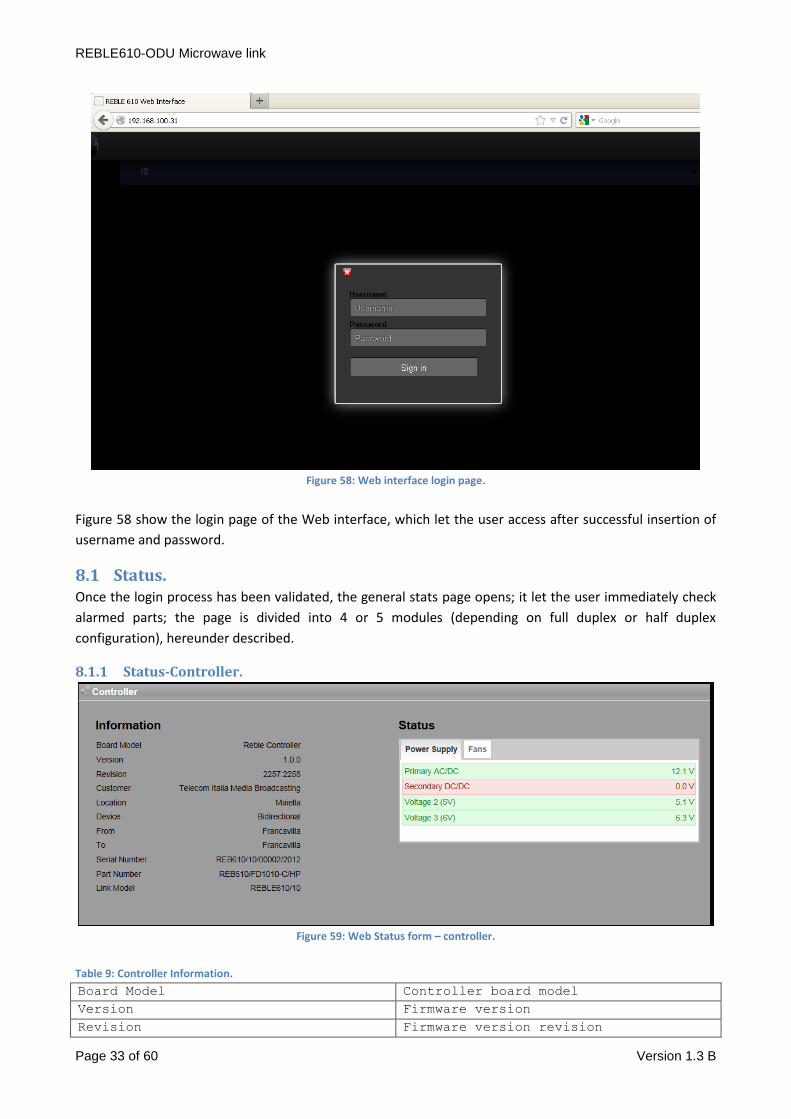
7.9 Menu Power Supply (PS). The Power Supply menu allows verifying whether both power supply modules are fed, what type of feeding
they are receiving and whether the secondary voltages are correct (+5V and +6V).
Figure 53: Power Supply menu.
Active areas:
Directional arrow “UP” to go back to main menu.
There is as well a general alarm indicator in case one of the voltage values is not being respected.
The upper zone of the menu is dynamically filled by the icon of the corresponding power supply module,
which can be in alternating or continuous current. It is hence possible to see the different combinations
reported in the following figures.
Figure 54: Icon power supply with continuous current,
primary position.
Figure 55: Icon power supply with continuous current,
secondary position.
Figure 56: Icon power supply with alternating current,
primary position.
Figure 57: Icon power supply with alt alternating current,
secondary position.
8 WEB interface. The REBLE610 is equipped with a WEB interface for an easier and intuitive monitoring and equipment
configuration.
The Web server connection can be achieved through RJ-45 connector in the front panel; with a very
common Web browser (like Internet Explorer, Mozilla Firefox, Google Chrome, Opera, Safari…) it is possible
to check equipment status and verify performances even remotely simply writing in the address bar the IP
address of the equipment. In order to check the IP address, please refer par.8.3.3.
REBLE610-ODU Microwave link
Page 33 of 60 Version 1.3 B
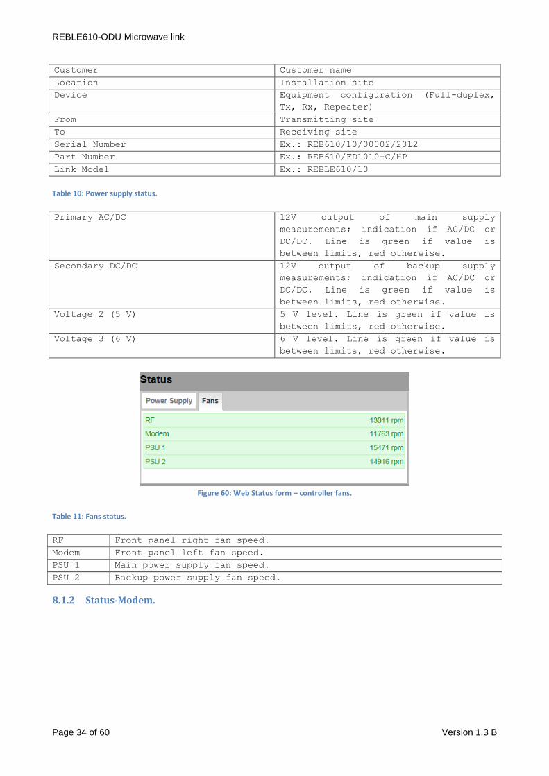
Figure 58: Web interface login page.
Figure 58 show the login page of the Web interface, which let the user access after successful insertion of
username and password.
8.1 Status. Once the login process has been validated, the general stats page opens; it let the user immediately check
alarmed parts; the page is divided into 4 or 5 modules (depending on full duplex or half duplex
configuration), hereunder described.
8.1.1 Status-Controller.
Figure 59: Web Status form – controller.
Table 9: Controller Information.
Board Model Controller board model
Version Firmware version
Revision Firmware version revision
REBLE610-ODU Microwave link
Page 34 of 60 Version 1.3 B
Customer Customer name
Location Installation site
Device Equipment configuration (Full-duplex,
Tx, Rx, Repeater)
From Transmitting site
To Receiving site
Serial Number Ex.: REB610/10/00002/2012
Part Number Ex.: REB610/FD1010-C/HP
Link Model Ex.: REBLE610/10
Table 10: Power supply status.
Primary AC/DC 12V output of main supply
measurements; indication if AC/DC or
DC/DC. Line is green if value is
between limits, red otherwise.
Secondary DC/DC 12V output of backup supply
measurements; indication if AC/DC or
DC/DC. Line is green if value is
between limits, red otherwise.
Voltage 2 (5 V) 5 V level. Line is green if value is
between limits, red otherwise.
Voltage 3 (6 V) 6 V level. Line is green if value is
between limits, red otherwise.
Figure 60: Web Status form – controller fans.
Table 11: Fans status.
RF Front panel right fan speed.
Modem Front panel left fan speed.
PSU 1 Main power supply fan speed.
PSU 2 Backup power supply fan speed.
8.1.2 Status-Modem.

REBLE610-ODU Microwave link
Page 35 of 60 Version 1.3 B
Figure 61: Web Status form – modem locked.
Figure 62: Web Status form – modem unlocked.
Table 12: Fans status.
Model Modem board model.
Version Modem board microcontroller firmware version.
Revision Modem board microcontroller firmware revision.
Temperature Temperature measurement on modem board.
Line is green if value is between limits, red otherwise.
Configuration in
use
Details of the configuration in use for the modem.
TX Profile Profile (modulation scheme) in use in the modulator.
Tx Bitrate Modulator Bitrate.
Tx Symbol Rate Modulator Symbol Rate.
Dem Acquire status Demodulator Locking status. Line is green if value is
between limits, red otherwise.
Normalized MSE Mean Square Error measurement, normalized according to the
used modulation. Line is green if value is between limits,
red otherwise.
RX Profile Profile (modulation scheme) in use in the demodulator
(automatically detected).
Rx Bitrate Demodulator bitrate.
Rx Symbol Rate Demodulator Symbol Rate.
LDPC stress Error Rate indication, detected by LDPC (Low Density Parity
Check) decoder. Line is green if value is between limits,
red otherwise.
Carrier Offset Carrier Offset compared to central frequency. Line is green
if value is between limits, red otherwise.
Internal AGC Internal AGC level. Line is green if value is between
limits, red otherwise.

REBLE610-ODU Microwave link
Page 36 of 60 Version 1.3 B
8.2 Status-Interface.
Figure 63: Web Status form – Interface BNC Status.
Table 13: SMPTE310/ASI/BTS connectors status.
Model Data interface board Model.
Version FPGA firmware version.
Revision FPGA firmware revision.
Bitrate [Mbps] ASI data stream bitrate.
Direction Connector (Input [IN] or output [OUT]).
Map Transport channel of the TS associated to related
connector.
Packet Length ASI format detected (188 or 204).
Signal Presence Signal presence detected indication.
Locked Signal lock indication.
Timing error Data stream locking error indication.
Overflow error Data buffer overflow indication.
Underflow error Data buffer underflow indication.
REBLE610-ODU Microwave link
Page 37 of 60 Version 1.3 B
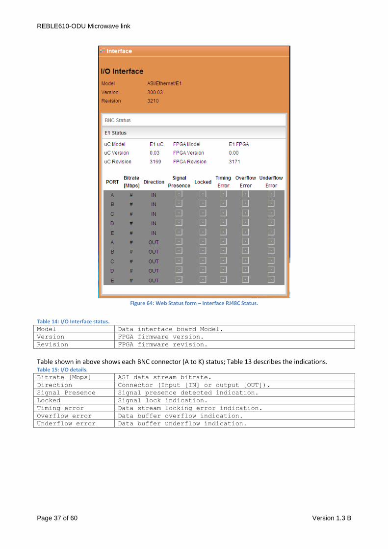
Figure 64: Web Status form – Interface RJ48C Status.
Table 14: I/O Interface status.
Model Data interface board Model.
Version FPGA firmware version.
Revision FPGA firmware revision.
Table shown in above shows each BNC connector (A to K) status; Table 13 describes the indications. Table 15: I/O details.
Bitrate [Mbps] ASI data stream bitrate.
Direction Connector (Input [IN] or output [OUT]).
Signal Presence Signal presence detected indication.
Locked Signal lock indication.
Timing error Data stream locking error indication.
Overflow error Data buffer overflow indication.
Underflow error Data buffer underflow indication.
REBLE610-ODU Microwave link
Page 38 of 60 Version 1.3 B
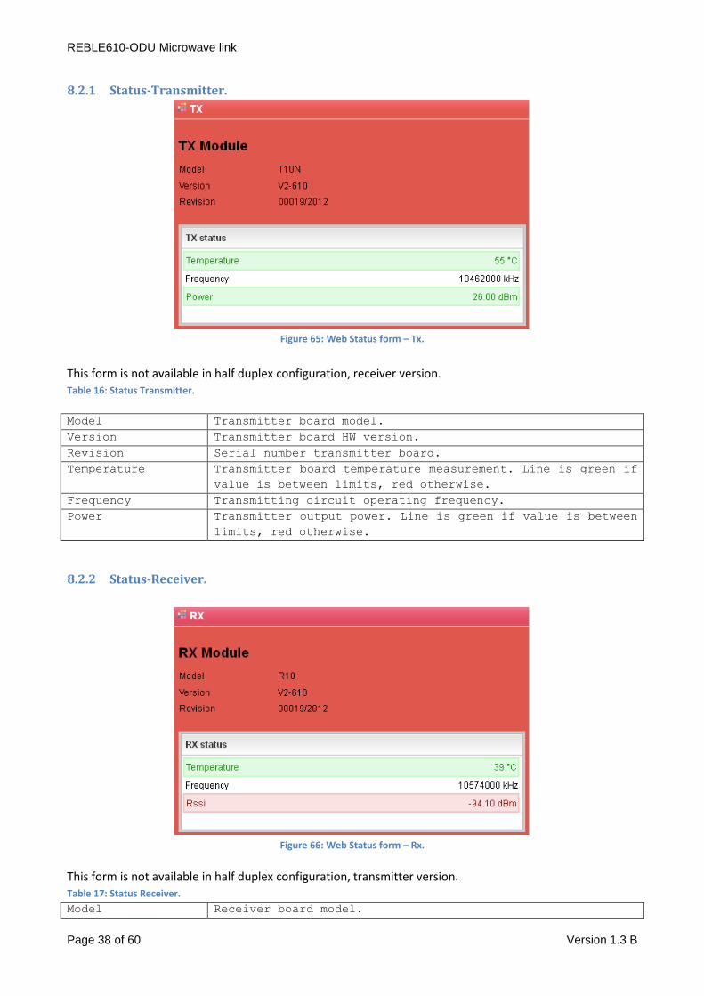
8.2.1 Status-Transmitter.
Figure 65: Web Status form – Tx.
This form is not available in half duplex configuration, receiver version. Table 16: Status Transmitter.
Model Transmitter board model.
Version Transmitter board HW version.
Revision Serial number transmitter board.
Temperature Transmitter board temperature measurement. Line is green if
value is between limits, red otherwise.
Frequency Transmitting circuit operating frequency.
Power Transmitter output power. Line is green if value is between
limits, red otherwise.
8.2.2 Status-Receiver.
Figure 66: Web Status form – Rx.
This form is not available in half duplex configuration, transmitter version. Table 17: Status Receiver.
Model Receiver board model.

REBLE610-ODU Microwave link
Page 39 of 60 Version 1.3 B
Version Receiver board HW version.
Revision Serial number receiver board.
Temperature Receiver board temperature measurement. Line is green if
value is between limits, red otherwise.
Frequency Receiving circuit operating frequency.
RSSI Signal level detected by receiver. Line is green if value
is between limits, red otherwise.
8.3 Tab Controller. Tab web concerning Controller is composed by six frames:
1. Coil fans.
2. Customer.
3. Network.
4. Trap Manager.
5. Tools.
6. Password Management.
8.3.1 Controller – Coil fans.
Figure 67: Web controller form – fans.
This frame let drive and monitor the functionality of front panel fans.
Checkbox Manual set in manual mode the configuration of the fans speed, measurable in Speed box in
rpm. In this case, it is necessary to manually set the speed.
In case checkbox Manual is disabled, on the contrary, it is required to establish temperature targets for
modules equipped with sensor, and the system controller will program fan controller so as to keep modules
at temperature set by the user.
Right fan is managed according to transmitter board temperature (if installed, so not available in half
duplex receiver configuration); left fan according to temperatures detected on modem and receiver boards.
Modifications are validated pushing Apply button. Table 18: Fan management.
Manual Checkbox fan manual management.
Speed(rpm) Only available in manual modality, shows the right fan
speed in rpm.
REBLE610-ODU Microwave link
Page 40 of 60 Version 1.3 B
Temperature target Target temperature for transmitter board (available in
automatic modality).
Rx Temperature
target
Target temperature for receiver board (available in
automatic modality and only for models with receiver).
Modem Temperature
target
Target temperature for modem board (available in automatic
modality).
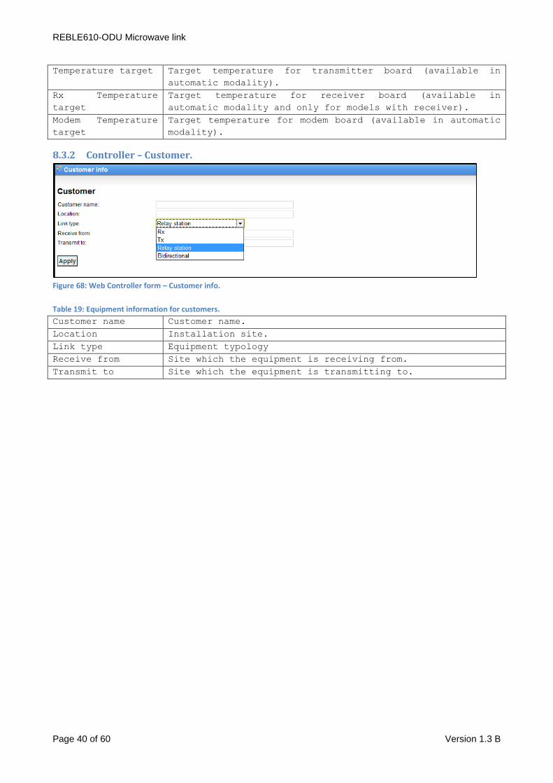
8.3.2 Controller – Customer.
Figure 68: Web Controller form – Customer info.
Table 19: Equipment information for customers.
Customer name Customer name.
Location Installation site.
Link type Equipment typology
Receive from Site which the equipment is receiving from.
Transmit to Site which the equipment is transmitting to.

REBLE610-ODU Microwave link
Page 41 of 60 Version 1.3 B
8.3.3 Controller – Network.
Figure 69: Web Controller form – Network Parameters.
This frame let check and modify network parameters of the user interface.
Ip Address, Netmask and Gateway Address can be modified by the user writing in the dedicated text box
while Mac Address is read-only. Moreover, it’s possible to configure a DNS, a NTP server IP address, the
Time Zone and the Country where the equipment is installed.
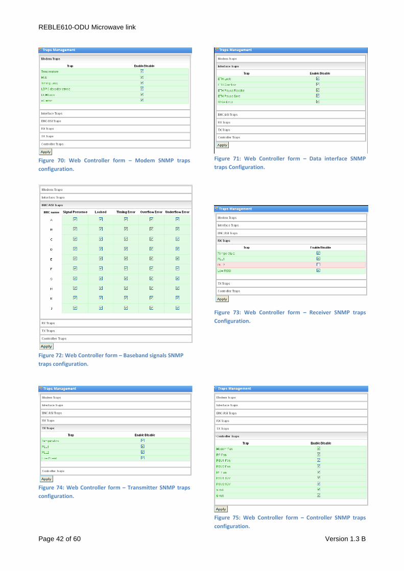
8.3.4 Controller – Trap Manager.
This frame let the user access to SNMP traps management; for every possible alarm is possible to enable or
disable the traps sending. Besides, it is possible to set their destination address.
REBLE610-ODU Microwave link
Page 42 of 60 Version 1.3 B
Figure 70: Web Controller form – Modem SNMP traps
configuration.
Figure 71: Web Controller form – Data interface SNMP
traps Configuration.
Figure 72: Web Controller form – Baseband signals SNMP
traps configuration.
Figure 73: Web Controller form – Receiver SNMP traps
Configuration.
Figure 74: Web Controller form – Transmitter SNMP traps
configuration.
Figure 75: Web Controller form – Controller SNMP traps
configuration.

REBLE610-ODU Microwave link
Page 43 of 60 Version 1.3 B
Figure 76: Web Controller form – Trap Destination configuration.
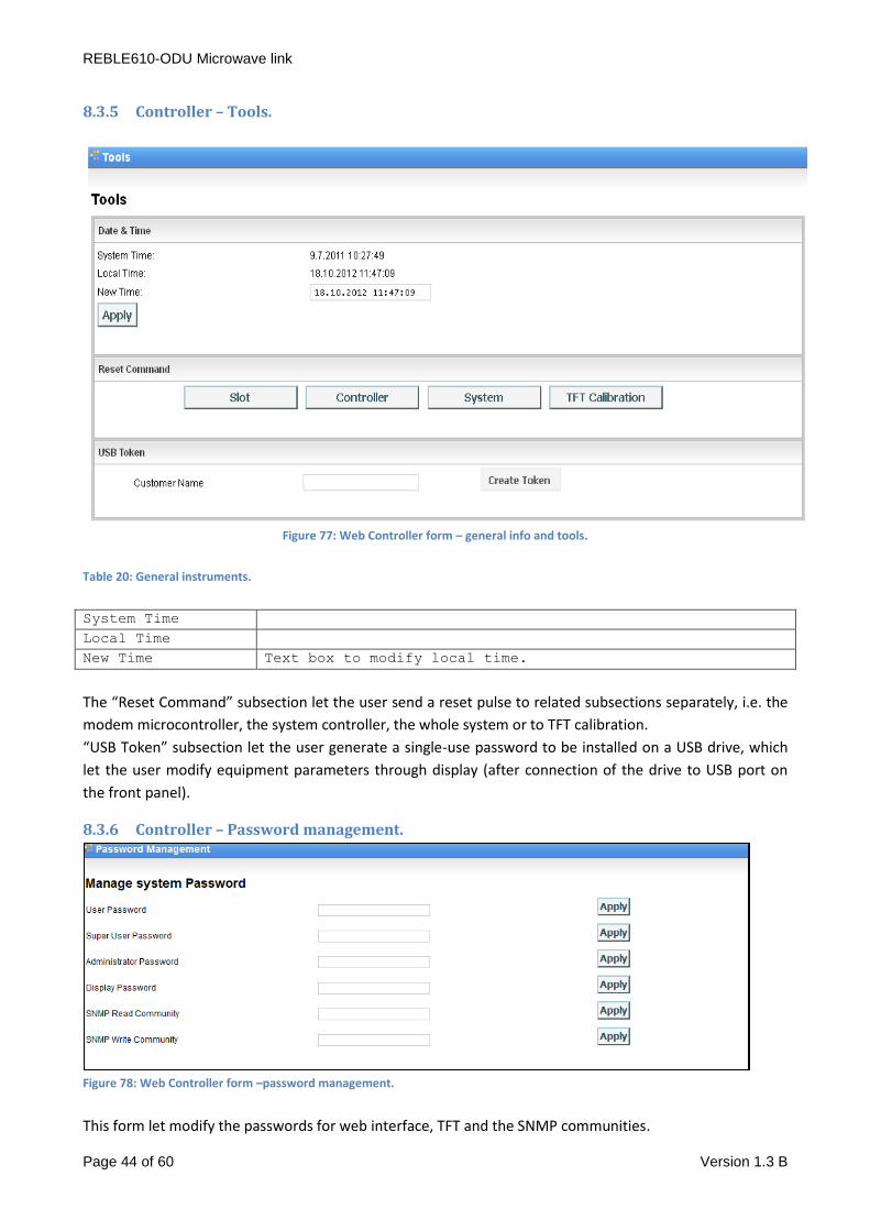
REBLE610-ODU Microwave link
Page 44 of 60 Version 1.3 B
8.3.5 Controller – Tools.
Figure 77: Web Controller form – general info and tools.
Table 20: General instruments.
System Time
Local Time
New Time Text box to modify local time.
The “Reset Command” subsection let the user send a reset pulse to related subsections separately, i.e. the
modem microcontroller, the system controller, the whole system or to TFT calibration.
“USB Token” subsection let the user generate a single-use password to be installed on a USB drive, which
let the user modify equipment parameters through display (after connection of the drive to USB port on
the front panel).
8.3.6 Controller – Password management.
Figure 78: Web Controller form –password management.
This form let modify the passwords for web interface, TFT and the SNMP communities.

REBLE610-ODU Microwave link
Page 45 of 60 Version 1.3 B
Passwords should be composed of at least six characters and cannot overcome fifteen characters.
The password level that can be modified is subject to the rights of the user. The user “User” cannot change
passwords. User “Super-User” can change its own and the “User” ones. The “Administrator” can change
any password.
8.4 Tab Slot. Web tab of the Controller board is composed by 4 sections:
- Modem
- Interface
- Tx
- Rx
8.4.1 Slot – Modem.
Web section of Modem board is composed by 5 frames, reporting information about both modulator and
demodulator part.
1. Status
2. MSE Graphic
3. Temperature Management
4. Profile Management
5. Operational Mode Management
Figure 79: Web slot modem form – status.
Status frame reports the information already shown in the homepage of the web interface. (See par. 8.1.2).
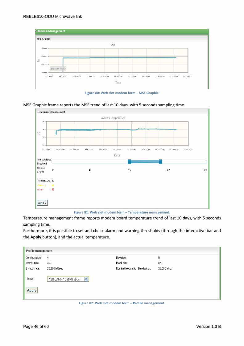
REBLE610-ODU Microwave link
Page 46 of 60 Version 1.3 B
Figure 80: Web slot modem form – MSE Graphic.
MSE Graphic frame reports the MSE trend of last 10 days, with 5 seconds sampling time.
Figure 81: Web slot modem form – Temperature management.
Temperature management frame reports modem board temperature trend of last 10 days, with 5 seconds
sampling time.
Furthermore, it is possible to set and check alarm and warning thresholds (through the interactive bar and
the Apply button), and the actual temperature.
Figure 82: Web slot modem form – Profile management.
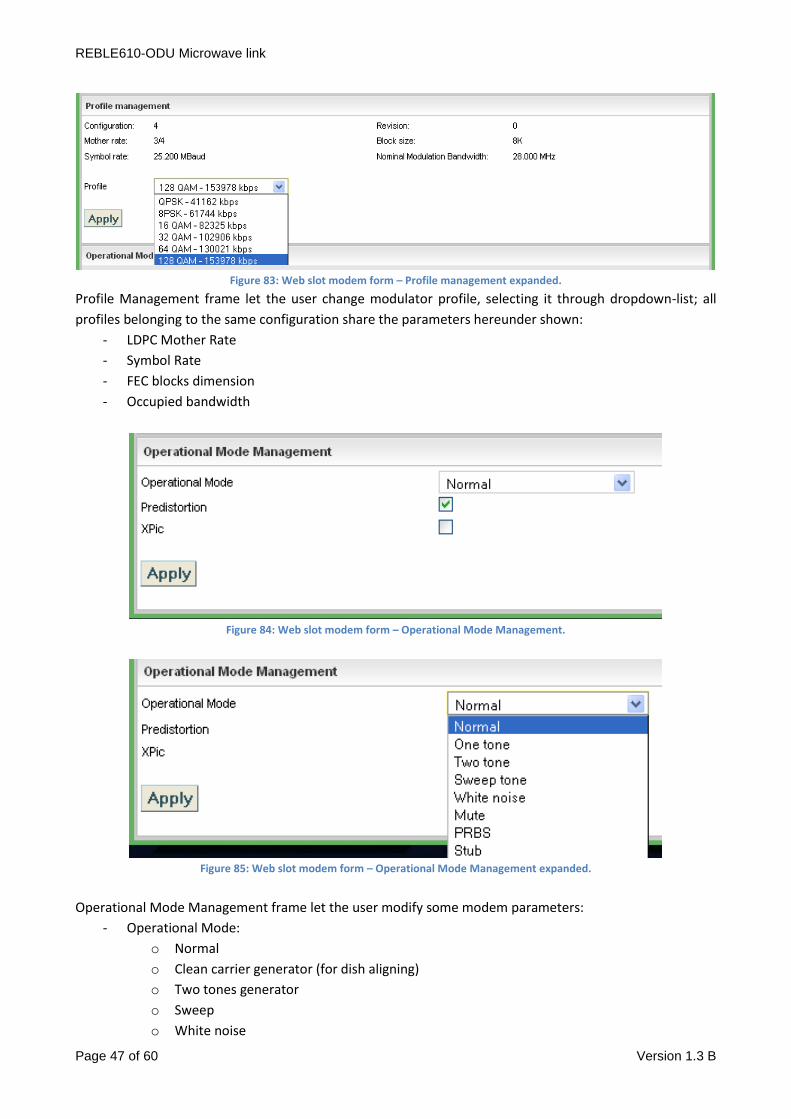
REBLE610-ODU Microwave link
Page 47 of 60 Version 1.3 B
Figure 83: Web slot modem form – Profile management expanded.
Profile Management frame let the user change modulator profile, selecting it through dropdown-list; all
profiles belonging to the same configuration share the parameters hereunder shown:
- LDPC Mother Rate
- Symbol Rate
- FEC blocks dimension
- Occupied bandwidth
Figure 84: Web slot modem form – Operational Mode Management.
Figure 85: Web slot modem form – Operational Mode Management expanded.
Operational Mode Management frame let the user modify some modem parameters:
- Operational Mode:
o Normal
o Clean carrier generator (for dish aligning)
o Two tones generator
o Sweep
o White noise

REBLE610-ODU Microwave link
Page 48 of 60 Version 1.3 B
o Mute
o PRBS
o Stub
- Pre-distortion enabling (recall factory defaults for each frequency)
- XPIC function enabling (only with related hardware option)

REBLE610-ODU Microwave link
Page 49 of 60 Version 1.3 B
8.4.2 Slot – Interface.
Web section of I/O Interface is composed by 4 frames:
1. Status
2. Input / Output port Management
3. Ethernet port Management
4. Transit Management
Figure 86: Web slot interface form – Status.
Status frame reports information already shown in the homepage (see par.8.2).
Figure 87: Web slot interface form – Input/Output ports management.
Input/output port management frame let the user configure signals on each BNC and RJ48C connector of the back panel; connectors are identified with ten letters (A, B, C, D, E) as per serigraphy (see par. 9.2) and for each one it is possible to:
1. Enable or disable the port. 2. Configure the port as input or output (just BNCs)
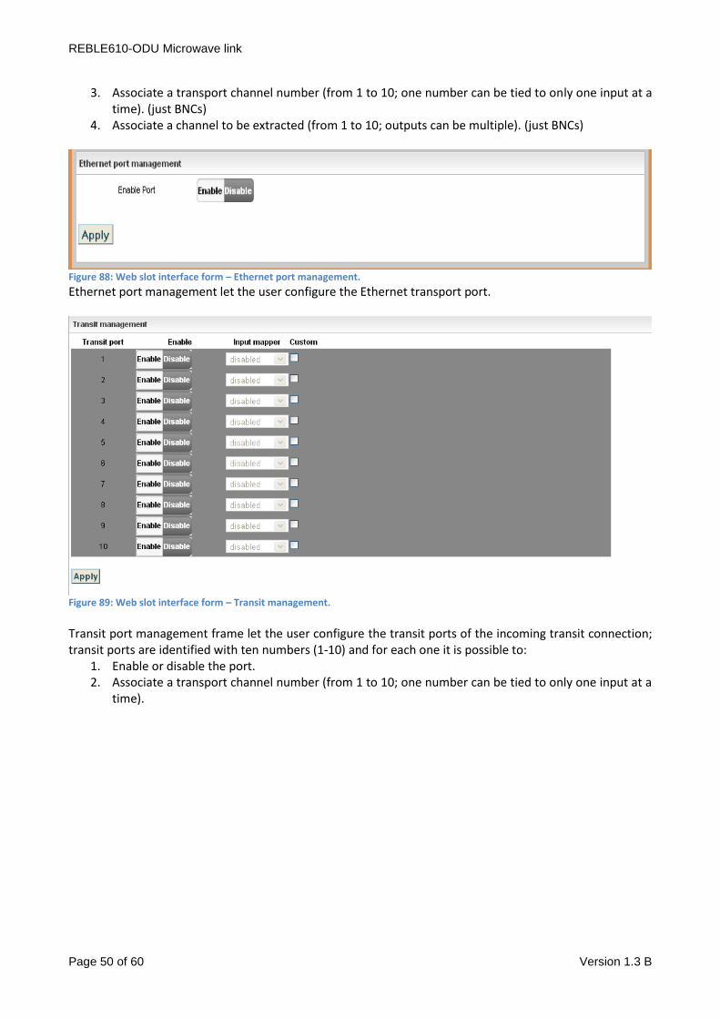
REBLE610-ODU Microwave link
Page 50 of 60 Version 1.3 B
3. Associate a transport channel number (from 1 to 10; one number can be tied to only one input at a time). (just BNCs)
4. Associate a channel to be extracted (from 1 to 10; outputs can be multiple). (just BNCs)
Figure 88: Web slot interface form – Ethernet port management.
Ethernet port management let the user configure the Ethernet transport port.
Figure 89: Web slot interface form – Transit management.
Transit port management frame let the user configure the transit ports of the incoming transit connection; transit ports are identified with ten numbers (1-10) and for each one it is possible to:
1. Enable or disable the port. 2. Associate a transport channel number (from 1 to 10; one number can be tied to only one input at a
time).

REBLE610-ODU Microwave link
Page 51 of 60 Version 1.3 B
8.4.3 Slot – TX.
Web section of transmitter board is composed by 4 frames:
1. Status
2. Temperature Management
3. Power Management
4. Frequency
Figure 90: Web slot TX form – status.
Status frame reports information already shown in homepage (see par.8.2.1).
Figure 91: Web slot TX form – Temperature management.
Temperature management frame reports transmitter board temperature trend of last 10 days, with 5
seconds sampling time. Furthermore, it is possible to set and check alarm and warning thresholds (through
the interactive bar and the Apply button), and the actual temperature.

REBLE610-ODU Microwave link
Page 52 of 60 Version 1.3 B
Figure 92: Web slot TX form – Power management.
Power management frame let the user manage transmitter output power, modifying it from factory default
calibration. Power, shown in lower part of the frame and measured in dBm, can be adjusted in a -2 to +2 dB
range from the calibration value. It is possible to mute the transmitter by clicking on the related switch in
the right part of the frame.
Figure 93: Web slot TX form – Frequency.
Frequency frame let the user change the transmitter frequency, depending on the factory limits (shown in
the interactive bar); by default, it is possible to modify the frequency in a +/- 5 MHz range (channel filter is
generally installed).
8.4.4 Slot – Rx.
Web section receiver board is composed by 4 frames:
1. Status
2. RSSI Graphic
3. Frequency
4. Temperature Management
Figure 94: Web slot Rx form – status.
Status frame reports information already shown in homepage (see par.8.2.2).
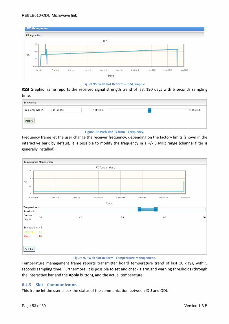
REBLE610-ODU Microwave link
Page 53 of 60 Version 1.3 B
Figure 95: Web slot Rx form – RSSI Graphic.
RSSI Graphic frame reports the received signal strength trend of last 190 days with 5 seconds sampling
time.
Figure 96: Web slot Rx form – Frequency.
Frequency frame let the user change the receiver frequency, depending on the factory limits (shown in the
interactive bar); by default, it is possible to modify the frequency in a +/- 5 MHz range (channel filter is
generally installed).
Figure 97: Web slot Rx form –Temperature Management.
Temperature management frame reports transmitter board temperature trend of last 10 days, with 5
seconds sampling time. Furthermore, it is possible to set and check alarm and warning thresholds (through
the interactive bar and the Apply button), and the actual temperature.
8.4.5 Slot – Communicator.
This frame let the user check the status of the communication between IDU and ODU.
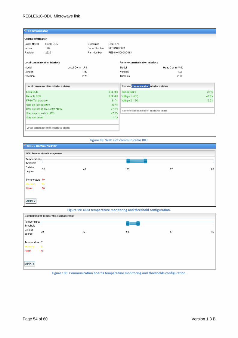
REBLE610-ODU Microwave link
Page 54 of 60 Version 1.3 B
Figure 98: Web slot communicator IDU.
Figure 99: ODU temperature monitoring and threshold configuration.
Figure 100: Communication boards temperature monitoring and thresholds configuration.

REBLE610-ODU Microwave link
Page 55 of 60 Version 1.3 B
Figure 101: Step-up temperature monitoring and thresholds configuration.
Figure 102: RF Head enabling/disabling frame.
The switch icon is intuitive for the user and let switch on or off the RF Head, for maintenance or
troubleshooting purposes. It has the same function of the real switch depicted in
8.5 Tab Upgrade. Web tab of the Upgrade is composed by 2 sections:
- Configuration uploader
- Machine upgrade
Figure 103: Web Upgrade form – Configuration File Uploader.
This frame let the user select a modem configuration, remove it from database, upload a new one and
check the stored ones.
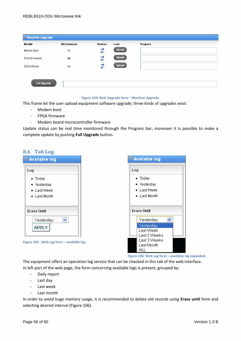
REBLE610-ODU Microwave link
Page 56 of 60 Version 1.3 B
Figure 104: Web Upgrade form – Machine Upgrade.
This frame let the user upload equipment software upgrade; three kinds of upgrades exist:
- Modem boot
- FPGA firmware
- Modem board microcontroller firmware
Update status can be real time monitored through the Progress bar; moreover it is possible to make a
complete update by pushing Full Upgrade button.
8.6 Tab Log.
Figure 105 : Web Log form – available log.
Figure 106: Web Log form – available log expanded.
The equipment offers an operation log service that can be checked in this tab of the web interface.
In left part of the web page, the form concerning available logs is present, grouped by:
- Daily report
- Last day
- Last week
- Last month
In order to avoid huge memory usage, it is recommended to delete old records using Erase until form and
selecting desired interval (Figure 106).

REBLE610-ODU Microwave link
Page 57 of 60 Version 1.3 B
In central part of the page, log messages are reported, organized in a table that can be ordered, filtered and
resized in terms of number of rows per page.
Records belong to 4 different categories are shown with different colors for user facility:
1. Messages
2. Configurations
3. Alarms
4. Warnings
Every record has a time, a description and an origin; an alarm event is described in appendix with
OCCURRED tag, while the alarm condition recovery is a Message with appendix RECOVERED. Records can
be ordered in every column and filtered (with related checkbox).
Log can be saved as .csv file with button SAVE TO DISK.
Figure 107: Web Log form – log.
Figure 108: Web Log form – filters.
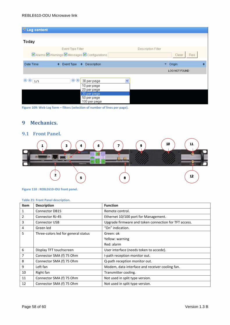
REBLE610-ODU Microwave link
Page 58 of 60 Version 1.3 B
Figure 109: Web Log form – filters (selection of number of lines per page).
9 Mechanics.
9.1 Front Panel.
Figure 110 : REBLE610-IDU front panel.
Table 21: Front Panel description.
Item Description Function
1 Connector DB15 Remote control.
2 Connector RJ-45 Ethernet 10/100 port for Management.
3 Connector USB Upgrade firmware and token connection for TFT access.
4 Green led “On” indication.
5 Three-colors led for general status Green: ok
Yellow: warning
Red: alarm
6 Display TFT touchscreen User interface (needs token to accede).
7 Connector SMA (f) 75 Ohm I-path reception monitor out.
8 Connector SMA (f) 75 Ohm Q-path reception monitor out.
9 Left fan Modem, data interface and receiver cooling fan.
10 Right fan Transmitter cooling.
11 Connector SMA (f) 75 Ohm Not used in split type version.
12 Connector SMA (f) 75 Ohm Not used in split type version.
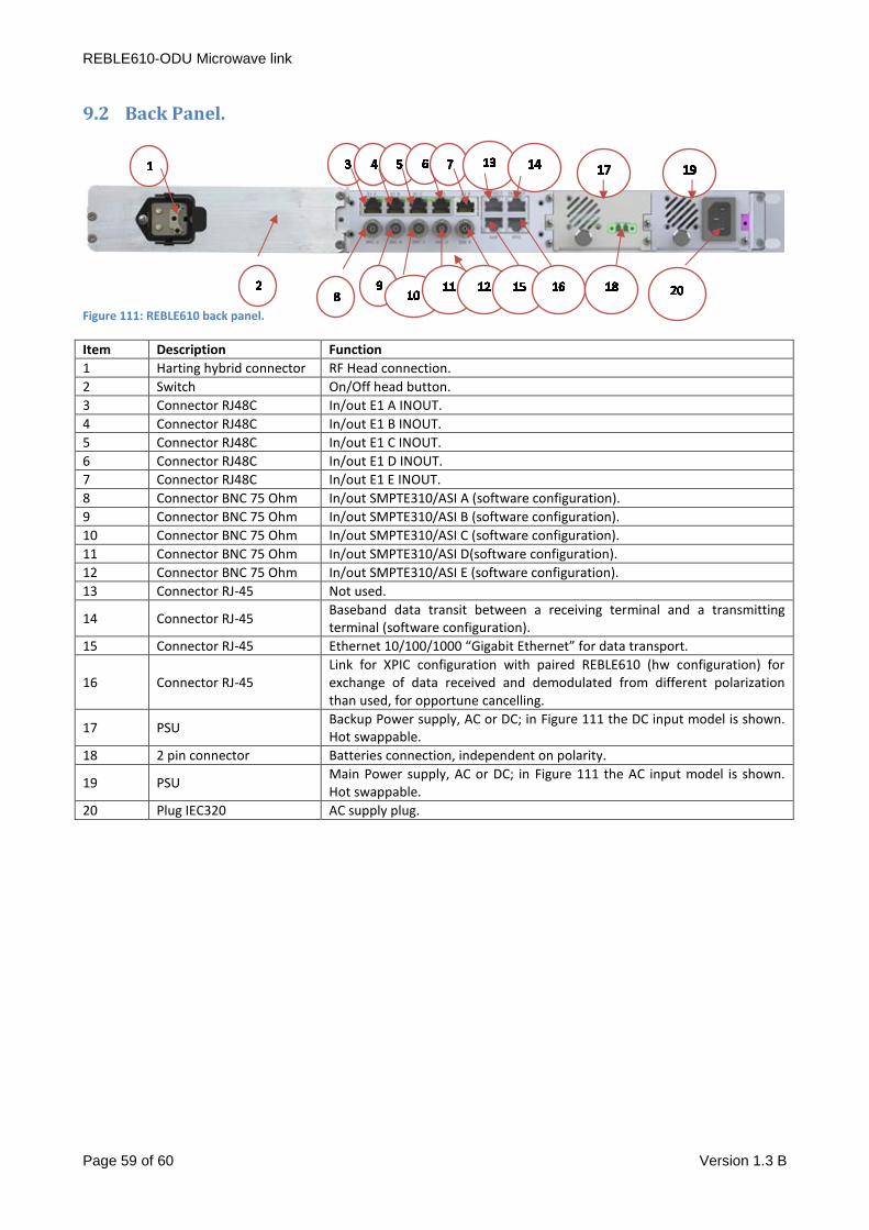
REBLE610-ODU Microwave link
Page 59 of 60 Version 1.3 B
9.2 Back Panel.
Figure 111: REBLE610 back panel.
Item Description Function
1 Harting hybrid connector RF Head connection.
2 Switch On/Off head button.
3 Connector RJ48C In/out E1 A INOUT.
4 Connector RJ48C In/out E1 B INOUT.
5 Connector RJ48C In/out E1 C INOUT.
6 Connector RJ48C In/out E1 D INOUT.
7 Connector RJ48C In/out E1 E INOUT.
8 Connector BNC 75 Ohm In/out SMPTE310/ASI A (software configuration).
9 Connector BNC 75 Ohm In/out SMPTE310/ASI B (software configuration).
10 Connector BNC 75 Ohm In/out SMPTE310/ASI C (software configuration).
11 Connector BNC 75 Ohm In/out SMPTE310/ASI D(software configuration).
12 Connector BNC 75 Ohm In/out SMPTE310/ASI E (software configuration).
13 Connector RJ-45 Not used.
14 Connector RJ-45 Baseband data transit between a receiving terminal and a transmitting terminal (software configuration).
15 Connector RJ-45 Ethernet 10/100/1000 “Gigabit Ethernet” for data transport.
16 Connector RJ-45 Link for XPIC configuration with paired REBLE610 (hw configuration) for exchange of data received and demodulated from different polarization than used, for opportune cancelling.
17 PSU Backup Power supply, AC or DC; in Figure 111 the DC input model is shown. Hot swappable.
18 2 pin connector Batteries connection, independent on polarity.
19 PSU Main Power supply, AC or DC; in Figure 111 the AC input model is shown. Hot swappable.
20 Plug IEC320 AC supply plug.
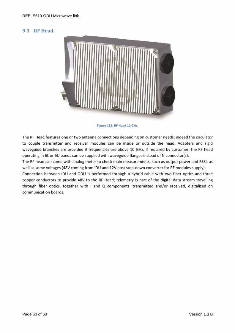
REBLE610-ODU Microwave link
Page 60 of 60 Version 1.3 B
9.3 RF Head.
Figure 112: RF Head 10 GHz.
The RF Head features one or two antenna connections depending on customer needs; indeed the circulator
to couple transmitter and receiver modules can be inside or outside the head. Adapters and rigid
waveguide branches are provided if frequencies are above 10 GHz. If required by customer, the RF head
operating in 6L or 6U bands can be supplied with waveguide flanges instead of N connector(s).
The RF head can come with analog meter to check main measurements, such as output power and RSSI, as
well as some voltages (48V coming from IDU and 12V post step-down converter for RF modules supply).
Connection between IDU and ODU is performed through a hybrid cable with two fiber optics and three
copper conductors to provide 48V to the RF Head; telemetry is part of the digital data stream travelling
through fiber optics, together with I and Q components, transmitted and/or received, digitalized on
communication boards.


![REBLE610 XPIC ASI-IP-SDH link - Elber S.r.l.DataSheets~REBLE610_[EN].pdf · The REBLE610 features an accurate hardware design, absence of internal cabling and full modularity. The](https://static.fdocuments.us/doc/165x107/5ad4b0287f8b9a571e8c8f2b/reble610-xpic-asi-ip-sdh-link-elber-srl-datasheetsreble610enpdfthe-reble610.jpg)