
Rebar Cutter Instruction & Parts Breakdown DC SERIES ... · by cutting improperly seated rebar that...
20
1 Rebar Cutter Instruction & Parts Breakdown DC SERIES PORTABLE REBAR CUTTERS DC-16LZ, DCC-1618, DC-16W, DC-20WH, DC-25X, DC-32WH Cutter_Instructions_FEB_2011_Full_Size • • • • • • • • • BN Products USA, LLC 3450 Sabin Brown Road Wickenburg, AZ 85390 (800) 992-3833 Fax: (928) 684-7041 [email protected] www.bnrebartools.com
Transcript of Rebar Cutter Instruction & Parts Breakdown DC SERIES ... · by cutting improperly seated rebar that...

1
Rebar Cutter Instruction& Parts Breakdown
DC SERIES PORTABLE REBAR CUTTERSDC-16LZ, DCC-1618, DC-16W,
DC-20WH, DC-25X, DC-32WH
Cutter_Instructions_FEB_2011_Full_Size
• • • • • • • • • BN Products USA, LLC3450 Sabin Brown RoadWickenburg, AZ 85390(800) 992-3833Fax: (928) [email protected]
2
IMPORTANT: READ THESE INSTRUCTIONS CAREFULLY
BEFORE ATTEMPTING TO USE YOUR TOOL!
Not knowing the proper operating procedures can lead to accidents. If you have any questions about any procedures, contact the nearest au-thorized distributor/agent or call Benner-Nawman, Inc.(800) 992-3833 or 928-684-2813.
CONTENTS
General Safety Precautions 3 Bleeding Instructions 3 Operation Instructions 3 Pre-use Checks 4 Parts and Specifications 4 Warm-up 4 Stopper Adjustment 4 Cutting 4 Points of Attention 4 Maintenance of Cutter Blocks 5 Cleaning 5 Oil-level Check 5 Oil Change 5 Bolt tightness 5 Carbon Brushes 5 General Safety Rules 6 Power Tool Care 6 DCC-1618 7 DC-16LZ 8 DC-16W 9 DC-20WH 10 DC-25X 11 DC-32WH 12
CUSTOMER SERVICE TOLL -FREE NUMBER:
(800) 992-3833WICKENBURG, ARIZIONA:
(928) 684-2813
3
GUARD AGAINST ELECTRIC SHOCK
To avoid possible shock, do not handle cutter with wet hands or use cutter in the rain or damp places. Be aware of all power lines, electric circuits and other hazards that may be contacted, espe-cially those that are below the surface or otherwise hidden from view. Never attempt to pick the tool up by use of the electric cord.
UNPLUG TOOL
Disconnect cutter from outlet when not in use and before cleaning, adjusting or servicing. Do not disconnect plug from outlet by pulling the cord. Always check that the switch lock is OFF before plug-ging in.
DO NOT CUTUNGRADED REBAR
MAINTAIN CUTTER WITH CARE
Inspect cutter before each application. Faulty or loose cutter blocks could result is personal injury. Keep handle dry, clean and free from oil and/or grease. Keep housing and piston free of dirt and iron filings. Check that no screws or bolts are loose or missing. Follow instructions for maintenance. Inspect switch, cord, plug and any extension cable at regular inter-vals. It is a good idea to inspect the hous-ing for any cracks before operating.
DO NOT EXCEED MAXIMUM CUTTING PRESSURE BY ADD-ING TO OR MODIFYING THE HYDRAULIC PUMP.
BLEEDING YOUR PORTABLE
REBAR CUTTER
You may have to bleed the hydraulics on your cutter if the tool runs unusually slow or doesn’t have the pressure to cut nor-mally. Do not run tool with low or no oil. For best results please follow these direc-tions:
1. If piston is still moving, run the tool for 2 minutes to warm the oil inside. If the piston is not moving, add oil before warming up for 2 minutes.
GENERAL SAFETY PRECAUTIONS
Use rebar cutters on maximum Grade 60 steel reinforcing bars only. These tools are not to be used in cutting other kinds of metal or materials. Do not cut ungraded rebar.
IMPORTANT:
Do not attempt to cut rebar by locking the off/on switch to the on position. This locking procedure is to be used only to warm the tool in cold climates or used with our hands free electrical box and foot operated switch. This is a safety is-sue and may cause damage to your rebar cutter. Always pull the on/off switch by hand for each individual cut. A foot op-erated switch and special electrical box are available if you want to use these cut-ters as production tools. Contact your lo-cal distributor or Benner-Nawman.
RESTRICT USE TO DESIGNATED MATERIALS
There is always a chance that the cut end may shoot out, especially if less than 30cm (1 foot) in length. Exceeding des-ignated material specifications greatly in-creases this risk and will also damage the tool. Do not attempt to cut rebars harder, thicker or thinner than specified.
USE EYE PROTECTION
Wear safety goggles, safety glasses with side shields or a face shield when using cutter.
PROVIDE SAFETY BARRIERS
Erect safety screens to protect coworkers from possible flying ends. Place a safety screen under the rebar when working in high places.
EXERCISE PROPER CONTROL
Hold cutter firmly and maintain proper footing and balance. Do not overreach. When working in a high place, secure cutter to scaffolding with a safety rope. Check that power cord is not fouled and keep cord away from sharp edges and heat. Check that all adjusting wrenches have been removed before using cutter.
2. When the oil is warm, run the piston out just before it returns and stop.
3. Remove the oil plug and top it off with oil.
4. Make a seal with your thumb over the oil plug opening.
5. Run the tool so that it makes a com-plete cycle.
6. When the piston is completely retract-ed in the open position, gently roll your thumb to let the unwanted air escape.
7. Repeat step #5 and #6 at least three times.
8. Add oil only when the piston is at least halfway out.
9. If you have to add additional oil, repeat #5 and #6.
10. Replace the oil plug and tighten it.
11. Make three or four cuts with rebar. The machine should now be working properly. Make sure that you observe ex-actly at what point the rebar is actually breaking.
12. Pinch a piece of rebar stopping just before it actually breaks.
13. Remove the oil plug again and top off the reserve one more time.
14. Replace the oil plug and tighten
15. The operation is now complete.
We recommend the following 20-wieght Non-Detergent Hydraulic Oils for use with our tools (anti-foam anti-abrasion): Tellus 68 (Shell), Rando HD 68 (Texaco) or Chevron AW 68 (Chevron). Hydraulic oil can also be ordered in quart contain-ers from your Diamond Tool Distributor.
OPERATING INSTRUCTIONS
CAUTION: Indicates hazard that could result in minor personal in-jury and/or product damage.
CARE: Indicates hazard that will result in product damage.
4
PRE-USE CHECKS
1. Check oil level. (See Maintenance)
2. Check condition of cutter blocks and tightness of cutter block bolts. (See Maintenance) - CHECK FOR CRACKS IN HOUSING
CAUTION: Using loose or cracked cutter blocks may result in injury to operator as well as damage to the tool.
3. Check that the power source is appro-priate to the cutter.
CARE: If voltage is too high, the motor will burn out. If voltage is too low, insufficient power will be generated. Never use DC current.
4. Check that power supply is properly grounded.
CAUTION: Failure to ground power supply may result in electric shock to operator (DC-16LZ, DC-16W and DC-32WH have double-insulated motors and do not require grounding.)
5. Check that cord is undamaged and that plug is not loose.
CAUTION: Cut or abraded cover-ing could result in a short and Electric shock to operator.
6. If an extensions cable is to be used, make sure that it is undamaged and that it is the proper wire gauge thickness for the length. See table below.
7. Before plugging in the tool, make sure that the switch lock is OFF.
CAUTION: If switch lock is ON, cutter will start as soon as it is plugged in. To disengage lock, pull trigger-switch and press lock-but-ton, which will pop out.
WARM-UP
In cold weather you should warm up the tool unit for 30-60 seconds so that the hydraulic oil reaches the proper viscosity. Pull trigger-switch to extend piston and release when it has reached its full stroke. Repeat 15-20 times.
STOPPER BOLT ADJUSTMENT
THE STOPPER BOLT IS PROB-ABLY THE MOST IMPORTANT PART OF YOUR PORTABLE CUTTER...
The adjustable stopper functions to main-tain the rebar in the correct position dur-ing cutting and must be properly set for each size of rebar before use.
1. Screw in stopper to provide sufficient clearance for rebar.
2. Insert rebar fully into U-shaped sup-port. Make sure that rebar is resting on the base of the support.
3. Keeping rebar at right angles (90 de-grees) to front cutter block, screw out stopper until it is just touching the rebar. Once set, the stopper needs no further adjustment while cutting rebar of the same diameter, but must be reset for a different size rebar.
CAUTION: Failure to correctly set the stopper bolt will result in ex-cessive wear of cutter blocks and may cause cut end to fly out. This will also lead to piston and cylinder damage.
CUTTING
1. Insert rebar between stopper and front cutter block, making sure that it is prop-erly seated in U-shaped support.
2. Pull trigger-switch and keep depressed while piston advances and rebar is cut. (If switch is released at an intermediate point, piston will stop.)
3. When cut is completed, release switch. Piston retracts automatically (Note that switch cannot be reactivated until piston has fully retracted.)
POINTS OF ATTENTION
1. Be especially careful when cutting off short lengths (30cm/12” or less) as the cut end tends to fly out.
CAUTION: Flying ends are a haz-ard to all personnel in the vicinity. Erect safety screens.
2. Do not cover air vents or operate the tool on dirt – use a plywood base under the rebar cutter to keep armature and fan clean
CARE: If the vents are covered, the motor will overheat and may burn out.
3. If hydraulic oil exceeds 70 degrees C (158 degrees F) in temperature, power will drop. Allow unit to cool before re-suming operation. (Be particularly care-ful in summer, when the aluminum pump case heats up quicker.)
4. If a drop in power is observed and mo-tor is unusually hot, check carbon-brush-es. (See maintenance)
5. If piston should ever fail to retract com-pletely, push rear cutter block backwards to manually retract piston or check under piston to remove and debris keeping the piston from retracting.
CAUTION: Use a rebar or flat metal bar for this purpose. Never push cutter block with any part of the hand, even if gloved.
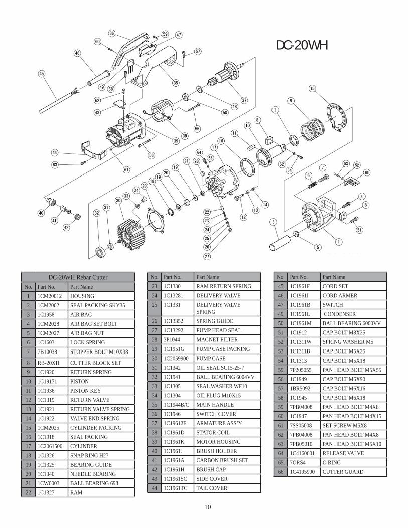
NOTE: Rebar cutters manufactured in after 2007 have a safety release valve for retracting the piston if it doesn’t return to the start position. This is usually caused by cutting improperly seated rebar that becomes jammed between the cutting blocks. On these newer models simply ro-tate the Allen set screw a quarter turn to retract the piston. On the DC-20WH, see parts breakdown part #64 for location of this release valve. Once piston has been retracted, pull trigger-switch long enough to partially advance piston. Unplug unit. Check pis-ton and housing for accumulated dirt and iron filings that may be jamming the pis-ton. (See Maintenance) If, after cleaning, piston still does not automatically retract when fully extended, the piston itself may be damaged. Return the unit to an autho-rized repair center or Benner-Nawman for repair.
Length 110/115 50/60 HzCable Size (AWG)
Up to 15mm (50 ft.) 14
Up to 30mm (100 ft.) 12
Up to 45mm (150 ft.) 10
5
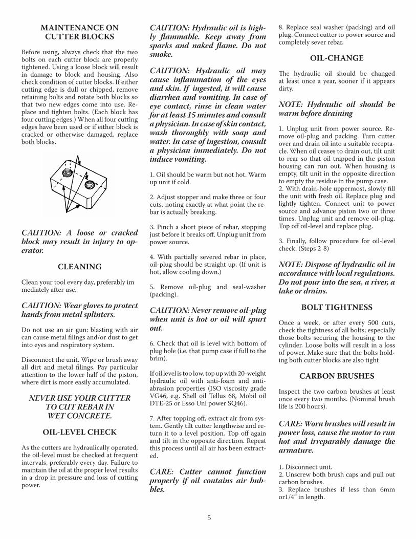
MAINTENANCE ON CUTTER BLOCKS
Before using, always check that the two bolts on each cutter block are properly tightened. Using a loose block will result in damage to block and housing. Also check condition of cutter blocks. If either cutting edge is dull or chipped, remove retaining bolts and rotate both blocks so that two new edges come into use. Re-place and tighten bolts. (Each block has four cutting edges.) When all four cutting edges have been used or if either block is cracked or otherwise damaged, replace both blocks.
CAUTION: A loose or cracked block may result in injury to op-erator.
CLEANING
Clean your tool every day, preferably immediately after use.
CAUTION: Wear gloves to protect hands from metal splinters.
Do not use an air gun: blasting with air can cause metal filings and/or dust to get into eyes and respiratory system.
Disconnect the unit. Wipe or brush away all dirt and metal filings. Pay particular attention to the lower half of the piston, where dirt is more easily accumulated.
NEVER USE YOUR CUTTER TO CUT REBAR IN WET CONCRETE.
OIL-LEVEL CHECK
As the cutters are hydraulically operated, the oil-level must be checked at frequent intervals, preferably every day. Failure to maintain the oil at the proper level results in a drop in pressure and loss of cutting power.
CAUTION: Hydraulic oil is high-ly flammable. Keep away from sparks and naked flame. Do not smoke.
CAUTION: Hydraulic oil may cause inflammation of the eyes and skin. If ingested, it will cause diarrhea and vomiting. In case of eye contact, rinse in clean water for at least 15 minutes and consult a physician. In case of skin contact, wash thoroughly with soap and water. In case of ingestion, consult a physician immediately. Do not induce vomiting.
1. Oil should be warm but not hot. Warm up unit if cold.
2. Adjust stopper and make three or four cuts, noting exactly at what point the re-bar is actually breaking.
3. Pinch a short piece of rebar, stopping just before it breaks off. Unplug unit from power source.
4. With partially severed rebar in place, oil-plug should be straight up. (If unit is hot, allow cooling down.)
5. Remove oil-plug and seal-washer (packing).
CAUTION: Never remove oil-plug when unit is hot or oil will spurt out.
6. Check that oil is level with bottom of plug hole (i.e. that pump case if full to the brim).
If oil level is too low, top up with 20-weight hydraulic oil with anti-foam and anti-abrasion properties (ISO viscosity grade VG46, e.g. Shell oil Tellus 68, Mobil oil DTE-25 or Esso Uni power SQ46).
7. After topping off, extract air from sys-tem. Gently tilt cutter lengthwise and re-turn it to a level position. Top off again and tilt in the opposite direction. Repeat this process until all air has been extract-ed.
CARE: Cutter cannot function properly if oil contains air bub-bles.
8. Replace seal washer (packing) and oil plug. Connect cutter to power source and completely sever rebar.
OIL-CHANGE
The hydraulic oil should be changed at least once a year, sooner if it appears dirty.
NOTE: Hydraulic oil should be warm before draining
1. Unplug unit from power source. Re-move oil-plug and packing. Turn cutter over and drain oil into a suitable recepta-cle. When oil ceases to drain out, tilt unit to rear so that oil trapped in the piston housing can run out. When housing is empty, tilt unit in the opposite direction to empty the residue in the pump case.2. With drain-hole uppermost, slowly fill the unit with fresh oil. Replace plug and lightly tighten. Connect unit to power source and advance piston two or three times. Unplug unit and remove oil-plug. Top off oil-level and replace plug.
3. Finally, follow procedure for oil-level check. (Steps 2-8)
NOTE: Dispose of hydraulic oil in accordance with local regulations. Do not pour into the sea, a river, a lake or drains.
BOLT TIGHTNESS
Once a week, or after every 500 cuts, check the tightness of all bolts; especially those bolts securing the housing to the cylinder. Loose bolts will result in a loss of power. Make sure that the bolts hold-ing both cutter blocks are also tight
CARBON BRUSHES
Inspect the two carbon brushes at least once every two months. (Nominal brush life is 200 hours).
CARE: Worn brushes will result in power loss, cause the motor to run hot and irreparably damage the armature.
1. Disconnect unit.2. Unscrew both brush caps and pull out carbon brushes.3. Replace brushes if less than 6mm or1/4” in length.

6
OVERHAUL
Return the unit to an authorized agent for overhaul at least once every two years, sooner if subjected to heavy use. Call (800) 992-3833
GENERAL SAFETY RULES
WARNING: Read all instructions. Fail-ure to follow all instructions listed below may result in electric shock, fire and/or serious injury. The term “power tool” in all of the warnings listed below refers to your mains-operated (corded) power tool or battery-operated (cordless) power tool.
SAVE THESE INSTRUCTIONS
WORK AREA SAFETY
Keep work area clean and well lit. Clut-tered or dark areas invite accidents.
Do not operate power tools in explosive atmospheres, such as in the presence of flammable liquids, gases or dust. Power tools create sparks which may ignite the dust or fumes.
Keep children and bystanders away while operating a power tool. Distractions can cause you to lose control.
ELECTRICAL SAFETY
Power tool plugs must match the outlet. Never modify the plug in any way. Do not use any adapter plugs with earthed (grounded) power tools. Unmodified plugs and matching outlets will reduce risk of electric shock.
Avoid body contact with earthed or grounded surfaces such as pipes, radia-tors, ranges and refrigerators. There is an increased risk of electric shock if your body is earthed or grounded.
Do not expose power tools to rain or wet conditions. Water entering a power tool will increase the risk of electric shock.
Do not abuse the cord. Never use the cord for carrying, pulling or unplugging the power tool. Keep cord away from heat, oil sharp edges or moving parts. Damaged or entangled cords increase the risk of electric shock.
When operating a power tool outdoors, use an extension cord suitable to outdoor
use. Use a cord suitable for outdoor use reduces the risk of electric shock.
PERSONAL SAFETY
Stay alert, watch what you are doing and use common sense when operating a power tool. Do not use a power tool while you are tired or under the influ-ence of drugs, alcohol or medication. A moment of inattention while operating power tools may result in serious per-sonal injury.
Use safety equipment. Always wear eye protection. Safety equipment such as dust mask, non-skid safety shoes, hard hat, or hearing protection used for ap-propriate conditions will reduce personal injuries.
Avoid accidental starting. Ensure the switch is in the off-position before plug-ging in. Carrying power tools with your finger on the switch or plugging in power tools that have the switch on invites ac-cidents.
Remove any adjusting key or wrench be-fore turning the power tool on. A wrench or a key left attached to a rotating part of the power tool may result in personal in-jury.
Do not overreach. Keep proper footing and balance at all times. This enables better control of the power tool in unex-pected situations.Dress properly. Do not wear loose clothing or jewelry. Keep your hair, clothing and gloves away from mov-ing parts. Loose clothes, jewelry or long hair can be caught in moving parts.
If devices are provided for the connec-tion of dust extraction and collection fa-cilities, ensure these are connected and properly used. Use of these devices can reduce dust-related hazards.
POWER TOOL USE AND CARE
Do not force the power tool. Use the cor-rect power tool for your application. The correct power tool will do the job better and safer at the rate for which it was de-signed.Do not use the power tool if the switch does not turn it on and off. Any power tool that cannot be controlled with the switch is dangerous and must be re-paired.
Disconnect the plug from the power source and/or the battery pack from the power tool before making any adjust-ments, changing accessories, or storing power tools. Such preventative safety measures reduce the risk of starting the power tool accidentally.
Store idle power tools out of the reach of children and do not allow persons un-familiar with the power tools or these instructions to operate the power tool. Power tools are dangerous in the hands of untrained users.
Maintain power tools. Check for mis-alignment or binding or moving parts, breakage of parts and any other condition that may affect the power tools operation. If damaged, have the power tool repaired before use. Many accidents are caused by poorly maintained power tools.
Keep cutting tools sharp and clean. Prop-erly maintained cutting tools with sharp cutting edges are less likely to bind and are easier to control.
Use the power tool, accessories and tool bits etc., in accordance with these in-structions and in the manner intended for the particular type of power tool, tak-ing into account the working conditions and the work to be performed. Use of the power tool for operations different from those intended could result in a hazard-ous situation.
SERVICE
Have your power tool serviced by a quali-fied repair person using only identical re-placement parts. This will ensure that the safety of the power tool is maintained.
For a Service Repair Center nearest you please call (800)992-3833 or go on- line
www.bnrebartools.com
BN Products USA, LLC3450 Sabin Brown Road
Wickenburg, Arizona 85390(800) 992-3833 or
(928) 684-2813Fax: (928) 684-7041
7
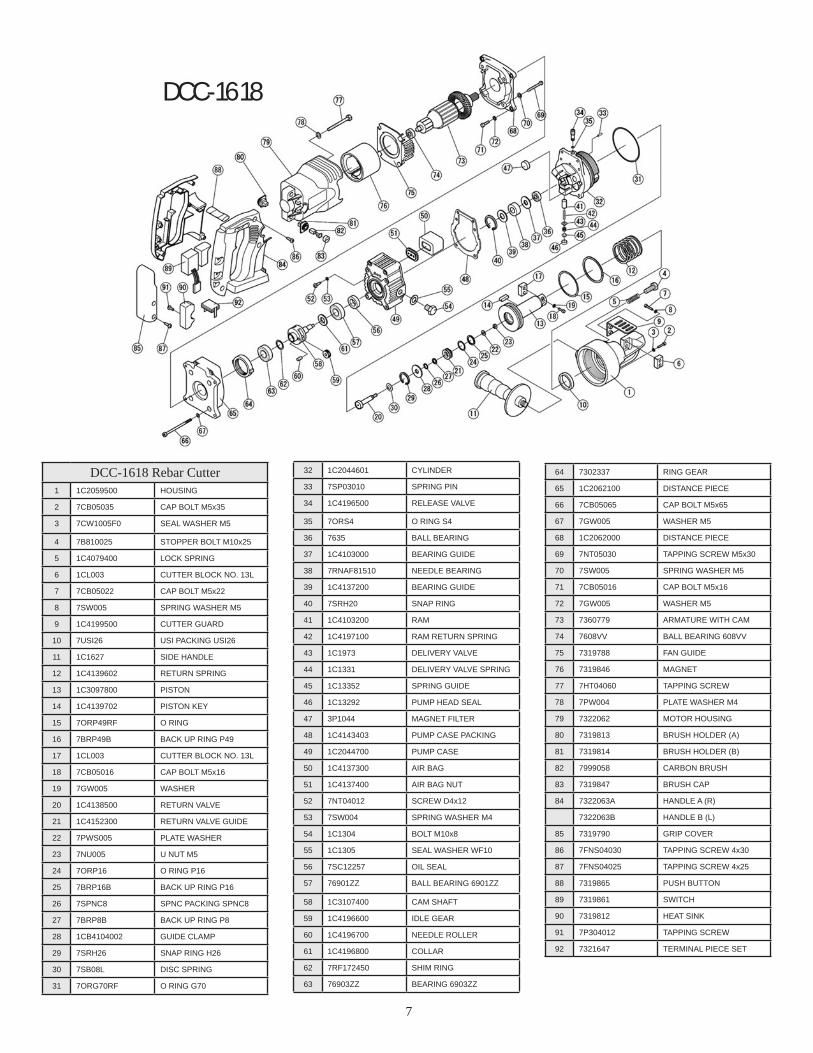
DCC-1618 Rebar Cutter1 1C2059500 HOUSING
2 7CB05035 CAP BOLT M5x35
3 7CW1005F0 SEAL WASHER M5
4 7B810025 STOPPER BOLT M10x25
5 1C4079400 LOCK SPRING
6 1CL003 CUTTER BLOCK NO. 13L
7 7CB05022 CAP BOLT M5x22
8 7SW005 SPRING WASHER M5
9 1C4199500 CUTTER GUARD
10 7USI26 USI PACKING USI26
11 1C1627 SIDE HANDLE
12 1C4139602 RETURN SPRING
13 1C3097800 PISTON
14 1C4139702 PISTON KEY
15 7ORP49RF O RING
16 7BRP49B BACK UP RING P49
17 1CL003 CUTTER BLOCK NO. 13L
18 7CB05016 CAP BOLT M5x16
19 7GW005 WASHER
20 1C4138500 RETURN VALVE
21 1C4152300 RETURN VALVE GUIDE
22 7PWS005 PLATE WASHER
23 7NU005 U NUT M5
24 7ORP16 O RING P16
25 7BRP16B BACK UP RING P16
26 7SPNC8 SPNC PACKING SPNC8
27 7BRP8B BACK UP RING P8
28 1CB4104002 GUIDE CLAMP
29 7SRH26 SNAP RING H26
30 7SB08L DISC SPRING
31 7ORG70RF O RING G70
32 1C2044601 CYLINDER
33 7SP03010 SPRING PIN
34 1C4196500 RELEASE VALVE
35 7ORS4 O RING S4
36 7635 BALL BEARING
37 1C4103000 BEARING GUIDE
38 7RNAF81510 NEEDLE BEARING
39 1C4137200 BEARING GUIDE
40 7SRH20 SNAP RING
41 1C4103200 RAM
42 1C4197100 RAM RETURN SPRING
43 1C1973 DELIVERY VALVE
44 1C1331 DELIVERY VALVE SPRING
45 1C13352 SPRING GUIDE
46 1C13292 PUMP HEAD SEAL
47 3P1044 MAGNET FILTER
48 1C4143403 PUMP CASE PACKING
49 1C2044700 PUMP CASE
50 1C4137300 AIR BAG
51 1C4137400 AIR BAG NUT
52 7NT04012 SCREW D4x12
53 7SW004 SPRING WASHER M4
54 1C1304 BOLT M10x8
55 1C1305 SEAL WASHER WF10
56 7SC12257 OIL SEAL
57 76901ZZ BALL BEARING 6901ZZ
58 1C3107400 CAM SHAFT
59 1C4196600 IDLE GEAR
60 1C4196700 NEEDLE ROLLER
61 1C4196800 COLLAR
62 7RF172450 SHIM RING
63 76903ZZ BEARING 6903ZZ
64 7302337 RING GEAR
65 1C2062100 DISTANCE PIECE
66 7CB05065 CAP BOLT M5x65
67 7GW005 WASHER M5
68 1C2062000 DISTANCE PIECE
69 7NT05030 TAPPING SCREW M5x30
70 7SW005 SPRING WASHER M5
71 7CB05016 CAP BOLT M5x16
72 7GW005 WASHER M5
73 7360779 ARMATURE WITH CAM
74 7608VV BALL BEARING 608VV
75 7319788 FAN GUIDE
76 7319846 MAGNET
77 7HT04060 TAPPING SCREW
78 7PW004 PLATE WASHER M4
79 7322062 MOTOR HOUSING
80 7319813 BRUSH HOLDER (A)
81 7319814 BRUSH HOLDER (B)
82 7999058 CARBON BRUSH
83 7319847 BRUSH CAP
84 7322063A HANDLE A (R)
7322063B HANDLE B (L)
85 7319790 GRIP COVER
86 7FNS04030 TAPPING SCREW 4x30
87 7FNS04025 TAPPING SCREW 4x25
88 7319865 PUSH BUTTON
89 7319861 SWITCH
90 7319812 HEAT SINK
91 7P304012 TAPPING SCREW
92 7321647 TERMINAL PIECE SET
DCC-1618

8
DC-16LZ Rebar Cutter1 1C2025700 HOUSING (DC-16LZ)
2 70RP30 O RING P30
3 1C16021 SEAL PACKING SKY30
4 RB-16LZ CUTTER BLOCK SET
5 7CB05015 CAP BOLT M5XM15
6 7SW0005 SPRING WASHER M5
7 7B810025 STOPPER BOLT M10X25
8 1C4079400 LOCK SPRING
9 1C4078900 AIR BAG
10 7ST0612 TAPPING SCREW (+) 6×12
11 1C4079000 AIRBAG NUT
12 7CB08022 CAP BOLT M8X22
13 1C3039700 PISTON
14 7FU0825L0 SEAL PACKING OSI66-56-6
15 1C4079701 PISTON KEY 7X8X24
17 1CL0123 RETURN VALVE
18 1CL0143 RETURN VALVE SPRING
19 1C1922 VALVE END SPRING
20 SEE 6 SEE 6
21 7CB05015 CAP BOLT M5X15
22 7SW0005 SPRING WASHER M5
23 1CL016 RETURN SPRING
24 1C2025600 CYLINDER
25 70RG60 O RING
26 1C1971 RAM
27 1C1972 RAM RETURN SPRING
28 1C1973 DELIVERY VALVE
29 1C1331 DELIVERY VALVE SPRING
30 1C13352 SPRING GUIDE
31 1C13292 PUMP HEAD SEAL
32 3P1030 BEARING 608
33 1C1325 BEARING GUIDE
34 1C1340 NEEDLE BEARING
35 1C1326 SNAP RING H27
36 3P1044 MAGNET FILTER
37 1C4079300 PUMP CASE PACKING
38 7SB0812 OIL PLUG M8×12
39 70RP10 O RING P-10
40 1C2025800 PUMP CASE
41 1C1342 OIL SEAL
42 76002VV BALL BEARING 6002VV
43 3V0001E ARMATURE WITH CAM
44 7608VV BALL BEARING
45 1CL001P BEARING LOCK
46 3V0001D STATOR COIL
47 7HT04070 TAPPING SCREW D4X70
48 7SW0004 SPRING WASHER M4
49 3V0001K MOTOR HOUSING
50 1CL001C BRUSH HOLDER
51 1C1361A CARBON BRUSH SET
52 3V0001P HOLDER PIECE
53 7NS04016 TAPPING SCREW D4X16
54 3V0001W CONDENSER
55 4V0001N SWITCH
56 7WB035006 SCREW M3.5X6
57 3V0001R LEAD WIRE
58 3V0001Z CORD ARMER
59 4V001V CORD SET
60 1CL001Q CORD CLIP
61 7FNS04016 TAPPING SCREW D4X16
62 3V0001L HANDLE COVER
63 7WNS04020 TAPPING SCREW D4X20
64 3V0001V FOOT
65 3V0001S SLEEVE
66 7PW0005 PLATE WASHER M5
67 7CB05075 CAP BOLT M5X75
68 NAME PLATE
69 7R020032 RIVET
73 1CL001R SUPPORT B
74 1CL001M CONNECTOR
75 1DBR2943 STEEL BALL 5/32
DC-16LZ

9
DC-16W Rebar Cutter1 1CW0001 CYLINDER (DC 16X)
2 1CW0003 BALL BEARING 698
3 1C1327 RAM
4 1C1330 RAM RETURN SPRING
5 1C13281 DELIVERY VALVE
6 1C1331 DELIVERY VALVE SPRING
7 1C13352 SPRING GUIDE
8 1C13292 PUMP HEAD SEAL
9 3P1044 MAGNET FILTER
10 1C1615 PUMP CASE PACKING
11 1C1325 BEARING GUIDE
12 1C1340 NEEDLE BEARING
13 1C1325 BEARING GUIDE
14 1C1326 SNAP RING H27
15 4V0001A PUMP CASE
16 7SD15257 OIL SEAL
17 7HR26 SNAP RING H26
18 76002VV BALL BEARING 6002VV
19 1C1305 SEAL WASHER
20 1C1304 OIL PLUG M10x15
21 1C1604 SEAL PACKING
22 1C16182 PISTON KEY
24 1C1319 RETURN VALVE
25 1CL0143 RETURN VALVE SPRING
26 1C16172 PISTON
27 1C1323 VALVE END SPRING
28 1C16012 HOUSING
29 1C1616 AIR BAG
30 1C1620 AIR BAG NUT
31 7SW0008 SPRING WASHER M8
32 1CM2-28 AIR BAG SET BOLT
33 1C16142 CYLINDER PACKING
34 1C16021 SEAL PACKING SKY30
35 1C16052 RETURN SPRING
36 7CB06020 CAP BOLT M6x20
37 7CB06020 CAP BOLT M6x20
38 RB-16X CUTTER BLOCK SET
39 7SW0005 SPRING WASHER M5
40 7CB05018 CAP BOLT M5x18
41 SEE 38 SEE 38
42 7GW0005 WASHER M5
43 7CB05015 CAP BOLT M5x15
44 1C1603 LOCK SPRING
45 7B810040 STOPPER BOLT M10X40
46 1C1627 SIDE HANDLE
47 7DN167 STICKER
49 4V0001B ARMATURE WITH CAM
50 4V0001J DUST SEAL (A)
51 7608VV BALL BEARING 608VV
52 4V0001G BEARING LOCK
53 7WNS05060 TAPPING SCREW D5x60
54 4V0001C STATOR COIL
55 4V0001H MOTOR HOUSING
56 4V0001K SLEEVE
57 4V0001L FOOT
58 7CB05080 CAP BOLT M5x80
59 7SS04005 SET SCREW M4x5
60 4V0001D BRUSH HOLDER
61 1C1961A CARBON BRUSH SET
62 4V0001E BRUSH CAP
63 4V0001P CONDENSER
64 4V0001Q SUPPORT (B)
65 4V0001N SWITCH
66 7WB035006 SWITCH BOLT M3.5X6
67 4V0001M SWITCH COVER
68 7WNS04020 TAPPING SCREW D4X20
69 4V0001S TERMINAL
70 4V0001T LEAD WIRE
71 4V0001U CONNECTOR 50091
72 4V0001W CONNECTOR 50092
73 4V0001R CORD CLIP
74 7FNS04016 TAPPING SCREW D4X16
75 4V0001X CORD ARMER
76 4V0001V CORD SET
77 7DN018 STICKER
78 7DN121 STICKER
79 7DN202 NAME PLATE
80 7R020032 RIVET
DC-16W
10
DC-20WH Rebar CutterNo. Part No. Part Name1 1CM20012 HOUSING2 1CM2002 SEAL PACKING SKY353 1C1958 AIR BAG4 1CM2028 AIR BAG SET BOLT5 1CM2027 AIR BAG NUT6 1C1603 LOCK SPRING 7 7B10038 STOPPER BOLT M10X38
8 RB-20XH CUTTER BLOCK SET9 1C1920 RETURN SPRING
10 1C19171 PISTON11 1C1936 PISTON KEY12 1C1319 RETURN VALVE13 1C1921 RETURN VALVE SPRING14 1C1922 VALVE END SPRING15 1CM2025 CYLINDER PACKING16 1C1918 SEAL PACKING17 1C2061500 CYLINDER18 1C1326 SNAP RING H2719 1C1325 BEARING GUIDE20 1C1340 NEEDLE BEARING21 1CW0003 BALL BEARING 69822 1C1327 RAM
No. Part No. Part Name23 1C1330 RAM RETURN SPRING24 1C13281 DELIVERY VALVE25 1C1331 DELIVERY VALVE
SPRING26 1C13352 SPRING GUIDE27 1C13292 PUMP HEAD SEAL28 3P1044 MAGNET FILTER29 1C1951G PUMP CASE PACKING30 1C2059900 PUMP CASE31 1C1342 OIL SEAL SC15-25-732 1C1941 BALL BEARING 6004VV33 1C1305 SEAL WASHER WF1034 1C1304 OIL PLUG M10X1535 1C1944B/C MAIN HANDLE36 1C1946 SWITCH COVER37 1C19612E ARMATURE ASS’Y38 1C1961D STATOR COIL39 1C1961K MOTOR HOUSING40 1C1961J BRUSH HOLDER41 1C1961A CARBON BRUSH SET42 1C1961H BRUSH CAP43 1C1961SC SIDE COVER44 1C1961TC TAIL COVER
No. Part No. Part Name45 1C1961F CORD SET46 1C1961I CORD ARMER47 1C1961B SWITCH49 1C1961L CONDENSER50 1C1961M BALL BEARING 6000VV51 1C1912 CAP BOLT M8X2552 1C1311W SPRING WASHER M553 1C1311B CAP BOLT M5X2554 1C1313 CAP BOLT M5X1855 7P205055 PAN HEAD BOLT M5X5556 1C1949 CAP BOLT M6X9057 1BR5092 CAP BOLT M6X1658 1C1945 CAP BOLT M6X1859 7PB04008 PAN HEAD BOLT M4X860 1C1947 PAN HEAD BOLT M4X1561 7SS05008 SET SCREW M5X862 7PB04008 PAN HEAD BOLT M4X863 7PB05010 PAN HEAD BOLT M5X1064 1C4160601 RELEASE VALVE65 7ORS4 O RING66 1C4195900 CUTTER GUARD
DC-20WH
11
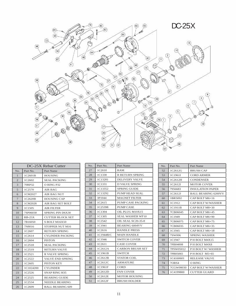
DC-25X Rebar CutterNo. Part No. Part Name
1 1C2601B HOUSING
2 1C2602 SEAL PACKING
3 70RP32 O RING P32
5 1C2570 AIR BAG
6 1CM2027 AIR BAG NUT
7 1C2620B HOUSING CAP
8 1CM2028 AIR BAG SET BOLT
9 1C1505 AIR FILTER
10 7SP06030 SPRING PIN D6X30
11 RB-25X CUTTER BLOCK SET
12 7B16050 S BOLT M16X50
13 7N8016 STOPPER NUT M16
14 1C2607 RETURN SPRING
15 1C2614 CYLINDER PACKING
16 1C2604 PISTON
17 1C2518 SEAL PACKING
18 1C2519 RETURN VALVE
19 1C2521 R VALVE SPRING
20 1C2522 VALVE END SPRING
21 1C2605 PISTON KEY
22 1C1024200 CYLINDER
23 1C2526 SNAP RING H35
24 1C2525 BEARING GUIDE
25 1C2534 NEEDLE BEARING
26 1C2609 BALL BEARING 609
No. Part No. Part Name
27 1C2610 RAM
28 1C1330 R RETURN SPRING
29 1C13281 DELIVERY VALVE
30 1C1331 D VALVE SPRING
31 1C13352 SPRING GUIDE
32 1C13292 PUMP HEAD SEAL
33 3P1044 MAGNET FILTER
34 1C2615 PUMP CASE PACKING
35 1C25398 PUMP CASE
36 1C1304 OIL PLUG M10X15
37 1C1305 SEAL WASHER WF10
38 1C2542 OIL SEAL SC20-35-8
39 1C1941 BEARING 6004VV
40 1C2616 HANDLE PRESS
41 1C1944B/C MAIN HANDLE
42 1C1946 SWITCH COVER
43 1C2611 CASE COVER
44 1C2612A CARBON BRUSH SET
45 1C1961B SWITCH
46 1C2612B STATOR COIL
47 1C2612C ARMATURE
48 1C1961F CORD
49 1C2612D FAN COVER
50 1C2612E MOTOR HOUSING
51 1C2612F BRUSH HOLDER
No. Part No. Part Name
52 1C2612G BRUSH CAP
53 1C1961I CORD ARMER
54 1C2612H CONDENSER
55 1C2612I MOTOR COVER
56 7956683 INSULATION PAPER
57 1C2612J BALL BEARING 6200VV
60 1BR5092 CAP BOLT M6×16
61 1C1912 CAP BOLT W/WASHER
62 1C1911B CAP BOLT M8×30
63 7CB06045 CAP BOLT M6×45
64 1C1949 CAP BOLT M6×90
65 7CB06075 CAP BOLT M6×75
66 7CB06035 CAP BOLT M6×35
67 1C1945 CAP BOLT M6×18
68 7SW006 SPRING WASHER
69 1C1947 P H BOLT M4X15
70 7PB04008 P H BOLT M4X8
71 7PSW05012 P H BOLT W/ WASHER
72 7PB05065 P H BOLT M5×65
73 1C4160601 RELEASE VALVE
74 7ORS4 O RING
75 7CGW08030 CAP BOLT W/WASHER
76 1C4199800 CUTTER GUARD
DC-25X

12
DC-32WH Rebar Cutter1 1C1022601 Housing (DC-32WH)
2 1C4172100 Sub handle
3 1C4172000 Collar
4 7PW0008 P. Washer M8
5 7SW0008 S. Washer M8
6 7B08020 Cap bolt M8x20
7 7ORP40 O ring P40
8 1C3258 Air bag
9 1C4171401 Air bag nut
10 1C4171601 Housing cap
11 7SP06036 Spring pin
12 1CM2028 Set bolt
13 7B11T20060 Bolt(11T) M20x60
14 7N11T0020 Nut(11T) M20-P2.5
15 7CB08035 Cap bolt M8x35
16 RB-32WH Cutter blocks
17 1C1911B Cap bolt M8×30
18 1C4171700 Handle spacer
19 7CB06025 Cap bolt M6×25
20 7CB10030 Cap bolt M10×30
21 1C3093600 Cylinder packing
22 1C4171900 Return spring
23 7CU0567KO Seal packing USH45-55-6
24 1C1911B Cap bolt M8×30
25 1C2056500 Piston
26 1C4184900 Piston key
28 7FU1078LO Seal packing OS1100-85-9
29 1C2522 Valve end spring
30 1C2521 Return valve spring
31 1C2519 Return valve
32 1C4139500 Steel ball 4.5
33 7ORS4 O ring S4
34 1C4160600 Release valve
35 1C1022901 Cylinder
36 1C2610 Ram
37 1C1330 Ram return spring
38 1C13281 Delivery valve
39 1C1331 Delivery valve spring
40 1C13352 Spring guide
41 1C13292 Pump head seal
42 3P1044 Magnet filter
43 1C2609 Ball bearing 609
44 1C2525 Bearing guide
45 1C2534 Needle bearing
46 1C2525 Bearing guide
47 1C2526 Snap ring H35
48 1C4165800 Pump case packing
49 1C1021301 Pump case
50 1C1305 Seal washer WF10
51 1C1304 Cap bolt M10×15
52 7GW0006 Teethed washer M6
53 7CB06055 Cap bolt M6×55
54 1C2542 Oil seal SC20-35-8
55 1C1941 Ball bearing 6004VV
56 7312435 Fan cover
57 7360406F Armature
58 1C2612J Ball bearing 62002RU
59 7340358F Stator coil
60 7312449 Motor housing
61 7984271 Tapping screw D5x75
62 7SW0005 P. Washer M5
63 7CB05045 Cap bolt M5×45
64 7SS05008 Cap bolt M5×8
65 7312434 Bearing bush
66 7980487 Brush holder
67 1C2612A Carbon brush
68 7940540 Brush cap
69 7981866 Handle A
70 7981867 Handle B
71 7990082 Support
72 1C1961B Switch
73 7994273 Condenser
74 1C4160400 Handle stay
75 1C1961I Cord armor
76 7990940 Distance piece
77 7CB06035 Cap bolt M6×35
78 7FCB06025 Flange socket M6×25
79 4V0001V Cord set
80 7956636 Tapping screw D4×25
81 1C4156001 Tube
82 7PW0006 P. Washer M6
83 7SW0005 S. Washer M5
84 7GW0008 Teethed washer M8
85 7SW0008 S. Washer M8
86 7CB08030 Cap bolt M8x16
DC-32WH
DBD-25X Bender Manual | Page 1
Tool ManualDBD-Series 0-180 degree Rebar Benders
BN Products-USA, LLC.3450 Sabin Brown Road Wickenburg, AZ 85390
(800) 992-3833 • (928) 684-2813 FAX: (928) 684-7041
[email protected] • www.bnrebartools.com
DBD-25XPORTABLE REBAR BENDER
DBD-25X Bender Manual | Page 2
NOTE: When using electric tools, basic safety precautions should always be followed to reduce the risk of electric shock and personal injury, including the followings items:
READ ALL INSTRUCTIONS AND SAVE THEM FOR FURTURE REFERENCE
1. Keep hands away. From all moving parts and rollers while operating.
2. Dress properly. Loose clothing or jewelry can get caught in moving parts. Wear sturdy boots with non-skid soles. Steel toed boots and safety glasses are recom-mended.
3. Keep children and bystanders away. Distractions can cause you to lose control.
4. Do not overreach. Keep proper footing and balance at all times. This enables better control of the power tool in unexpected situations.
5. Stay alert. Watch what you are doing and use common sense when operating a power tool. Do not use a power tool while you are tired or under the influence of drugs or alcohol. A moment of inattention while operating power tools may result in serious personal injury.
6. Do not exceed the maximum number of bars that can be bent at one time. Please refer to specifications.
7. When positioning the bar between rollers, make sure to lay it flat on the machine surface. Failure to do so may cause the rebar to fly out.
8. Do not expose tool to rain or use in damp locations.. Do not use tool in presence of flammable liquids or gases. Keep work area well lit. If the tool is used out-doors, keep it covered when not in use and protect it from rain or water.
9. Do not try to bend materials harder than “Grade 60 or 600N/mm2” as they will either crack and fly out or cause machine failure.
10. Disconnect tool from receptacle when not in use. Dis-connect when servicing or changing rollers to prevent accidents.
11. Keep tool clean at all times for best and safest perfor-mance. Follow instructions for lubricating and chang-ing parts. Keep hands dry and free of oil or grease. Inspect switches, tool cords periodically and have them repaired or replaced by an authorized service center if damaged. Check moving parts for alignment and binding as well as for breakage and improper mounting. Damaged parts should be repaired or replaced by an authorized service facility unless otherwise indicated in this instruction book.
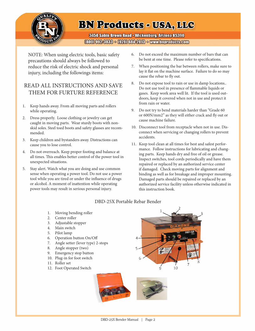
DBD-25X Portable Rebar Bender 1. Moving bending roller2. Center roller3. Adjustable stopper4. Main switch5. Pilot lamp6. Operation button On/Off7. Angle setter (lever type) 2-stops8. Angle stopper (two)9. Emergency stop button10. Plug-in for foot switch 11. Roller set12. Foot Operated Switch
DBD-25X Bender Manual | Page 3
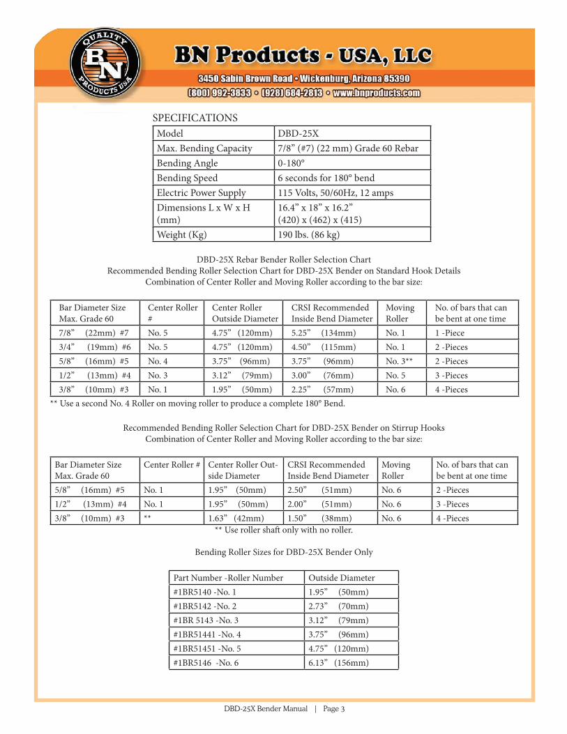
SPECIFICATIONSModel DBD-25XMax. Bending Capacity 7/8” (#7) (22 mm) Grade 60 RebarBending Angle 0-180°Bending Speed 6 seconds for 180° bendElectric Power Supply 115 Volts, 50/60Hz, 12 ampsDimensions L x W x H (mm)
16.4” x 18” x 16.2”(420) x (462) x (415)
Weight (Kg) 190 lbs. (86 kg)
DBD-25X Rebar Bender Roller Selection ChartRecommended Bending Roller Selection Chart for DBD-25X Bender on Standard Hook Details
Combination of Center Roller and Moving Roller according to the bar size:
Bar Diameter Size Max. Grade 60
Center Roller #
Center Roller Outside Diameter
CRSI Recommended Inside Bend Diameter
Moving Roller
No. of bars that can be bent at one time
7/8” (22mm) #7 No. 5 4.75” (120mm) 5.25” (134mm) No. 1 1 -Piece3/4” (19mm) #6 No. 5 4.75” (120mm) 4.50” (115mm) No. 1 2 -Pieces5/8” (16mm) #5 No. 4 3.75” (96mm) 3.75” (96mm) No. 3** 2 -Pieces1/2” (13mm) #4 No. 3 3.12” (79mm) 3.00” (76mm) No. 5 3 -Pieces3/8” (10mm) #3 No. 1 1.95” (50mm) 2.25” (57mm) No. 6 4 -Pieces
** Use a second No. 4 Roller on moving roller to produce a complete 180° Bend.
Recommended Bending Roller Selection Chart for DBD-25X Bender on Stirrup Hooks Combination of Center Roller and Moving Roller according to the bar size:
Bar Diameter Size Max. Grade 60
Center Roller # Center Roller Out-side Diameter
CRSI Recommended Inside Bend Diameter
Moving Roller
No. of bars that can be bent at one time
5/8” (16mm) #5 No. 1 1.95” (50mm) 2.50” (51mm) No. 6 2 -Pieces1/2” (13mm) #4 No. 1 1.95” (50mm) 2.00” (51mm) No. 6 3 -Pieces3/8” (10mm) #3 ** 1.63” (42mm) 1.50” (38mm) No. 6 4 -Pieces
** Use roller shaft only with no roller.
Bending Roller Sizes for DBD-25X Bender Only
Part Number -Roller Number Outside Diameter#1BR5140 -No. 1 1.95” (50mm)#1BR5142 -No. 2 2.73” (70mm)#1BR 5143 -No. 3 3.12” (79mm)#1BR51441 -No. 4 3.75” (96mm)#1BR51451 -No. 5 4.75” (120mm)#1BR5146 -No. 6 6.13” (156mm)
DBD-25X Bender Manual | Page 4
WARNING: ALWAYS UNPLUG THIS TOOL
BEFORE ATTACHING OR REMOVING ROLLERS OR
ACCESSORIES.
1. Select and set the correct rollers for the bars to be bent. See the table above.
2. Plug the electrical power cord into an appropriate outlet.
3. Lay the bar on the machine surface between the center roller and bending roller. Adjust the stopper so that the bar is parallel to the front edge of the machine.
4. Turn the main switch on and check that the pilot lamp has lit up.
5. Set the angle and make a test bend. If the bent angle is not exact, adjust the angle setter slightly to the right or left. Lock in the angle stoppers to duplicate the same angle each time.
6. Push the operation button or foot switch. The mov-ing bending roller will automatically return to the start position once the bend has been completed.
7. If it is necessary to stop the machine in an emer-gency, push the emergency stop button or release your foot from the foot operated switch. The bending roller will return to the start position automatically.
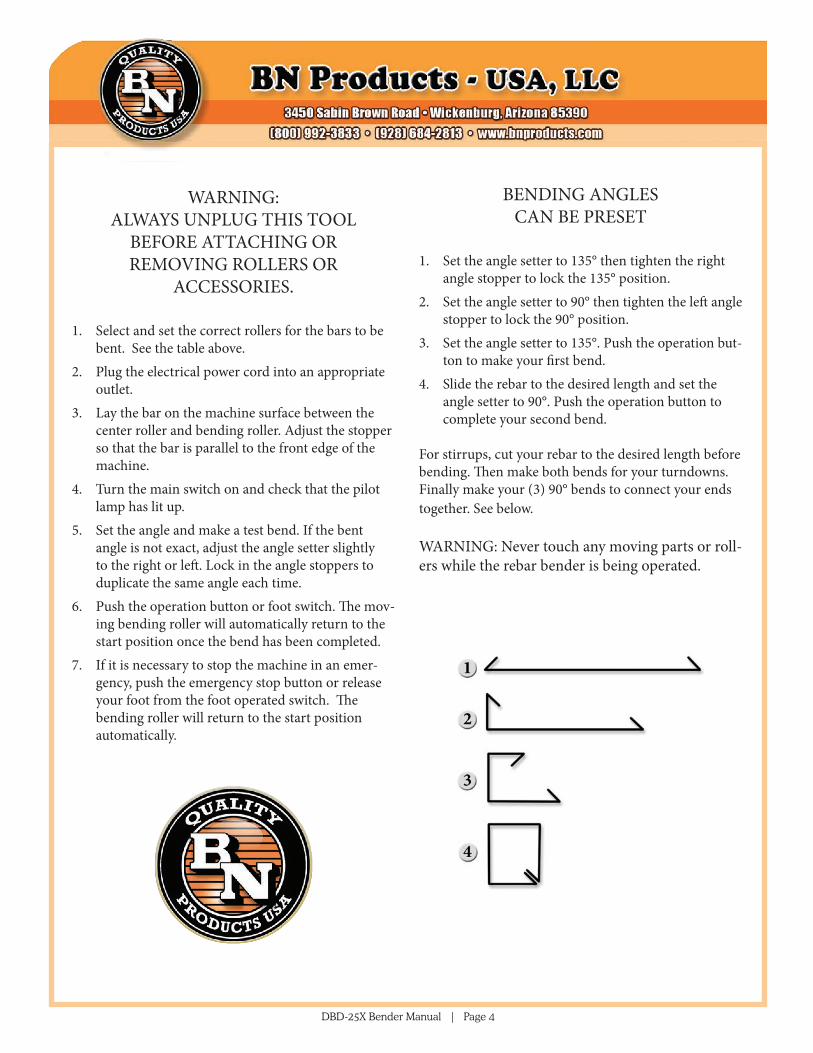
BENDING ANGLES CAN BE PRESET
1. Set the angle setter to 135° then tighten the right angle stopper to lock the 135° position.
2. Set the angle setter to 90° then tighten the left angle stopper to lock the 90° position.
3. Set the angle setter to 135°. Push the operation but-ton to make your first bend.
4. Slide the rebar to the desired length and set the angle setter to 90°. Push the operation button to complete your second bend.
For stirrups, cut your rebar to the desired length before bending. Then make both bends for your turndowns. Finally make your (3) 90° bends to connect your ends together. See below.
WARNING: Never touch any moving parts or roll-ers while the rebar bender is being operated.
DBD-25X Bender Manual | Page 5
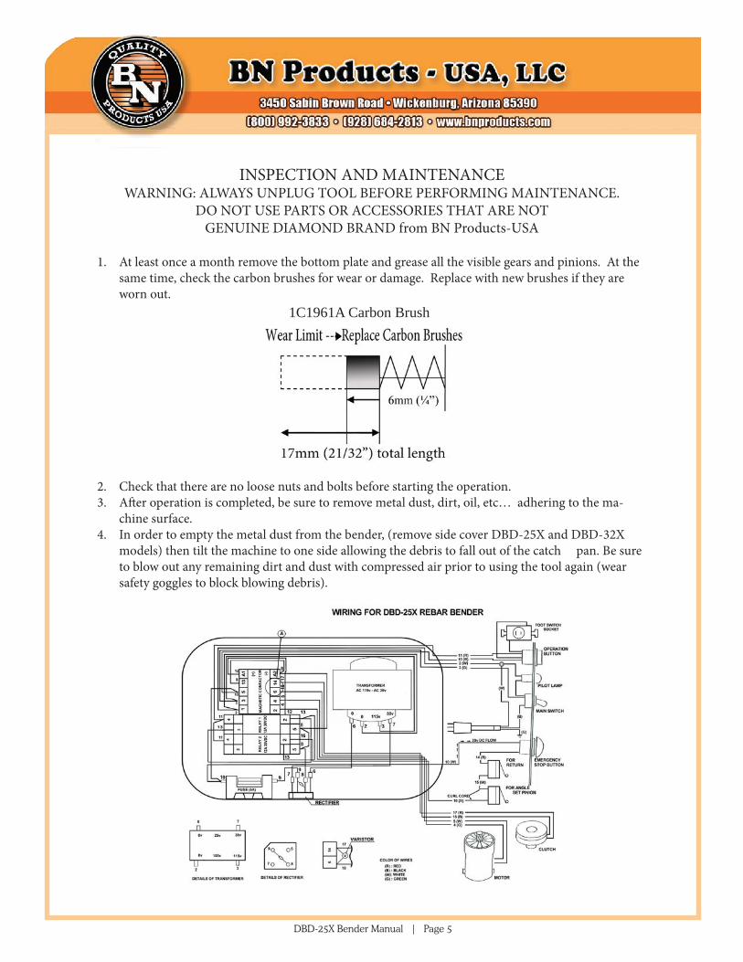
INSPECTION AND MAINTENANCE WARNING: ALWAYS UNPLUG TOOL BEFORE PERFORMING MAINTENANCE.
DO NOT USE PARTS OR ACCESSORIES THAT ARE NOT GENUINE DIAMOND BRAND from BN Products-USA
1. At least once a month remove the bottom plate and grease all the visible gears and pinions. At the same time, check the carbon brushes for wear or damage. Replace with new brushes if they are worn out.
2. Check that there are no loose nuts and bolts before starting the operation.3. After operation is completed, be sure to remove metal dust, dirt, oil, etc… adhering to the ma-
chine surface.4. In order to empty the metal dust from the bender, (remove side cover DBD-25X and DBD-32X
models) then tilt the machine to one side allowing the debris to fall out of the catch pan. Be sure to blow out any remaining dirt and dust with compressed air prior to using the tool again (wear safety goggles to block blowing debris).
1C1961A Carbon Brush
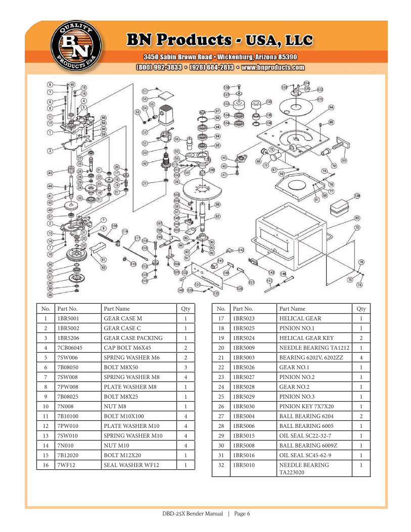
DBD-25X Bender Manual | Page 6
No. Part No. Part Name Qty1 1BR5001 GEAR CASE M 12 1BR5002 GEAR CASE C 13 1BR5206 GEAR CASE PACKING 14 7CB06045 CAP BOLT M6X45 25 7SW006 SPRING WASHER M6 26 7B08050 BOLT M8X50 37 7SW008 SPRING WASHER M8 48 7PW008 PLATE WASHER M8 19 7B08025 BOLT M8X25 1
10 7N008 NUT M8 111 7B10100 BOLT M10X100 412 7PW010 PLATE WASHER M10 413 7SW010 SPRING WASHER M10 414 7N010 NUT M10 415 7B12020 BOLT M12X20 116 7WF12 SEAL WASHER WF12 1
No. Part No. Part Name Qty17 1BR5023 HELICAL GEAR 118 1BR5025 PINION NO.1 119 1BR5024 HELICAL GEAR KEY 220 1BR5009 NEEDLE BEARING TA1212 121 1BR5003 BEARING 6202V, 6202ZZ 422 1BR5026 GEAR NO.1 123 1BR5027 PINION NO.2 124 1BR5028 GEAR NO.2 125 1BR5029 PINION NO.3 126 1BR5030 PINION KEY 7X7X20 127 1BR5004 BALL BEARING 6204 228 1BR5006 BALL BEARING 6005 129 1BR5015 OIL SEAL SC22-32-7 130 1BR5008 BALL BEARING 6009Z 131 1BR5016 OIL SEAL SC45-62-9 132 1BR5010 NEEDLE BEARING
TA2230201
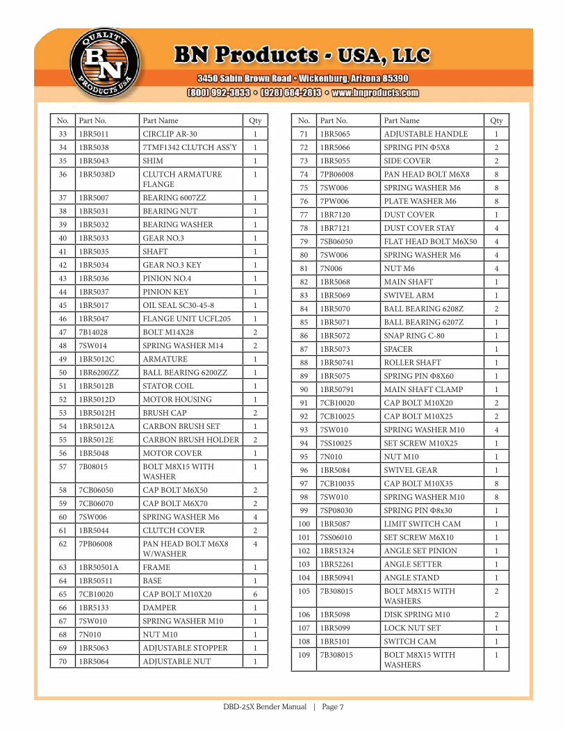
DBD-25X Bender Manual | Page 7
No. Part No. Part Name Qty33 1BR5011 CIRCLIP AR-30 134 1BR5038 7TMF1342 CLUTCH ASS’Y 135 1BR5043 SHIM 136 1BR5038D CLUTCH ARMATURE
FLANGE1
37 1BR5007 BEARING 6007ZZ 138 1BR5031 BEARING NUT 139 1BR5032 BEARING WASHER 140 1BR5033 GEAR NO.3 141 1BR5035 SHAFT 142 1BR5034 GEAR NO.3 KEY 143 1BR5036 PINION NO.4 144 1BR5037 PINION KEY 145 1BR5017 OIL SEAL SC30-45-8 146 1BR5047 FLANGE UNIT UCFL205 147 7B14028 BOLT M14X28 248 7SW014 SPRING WASHER M14 249 1BR5012C ARMATURE 150 1BR6200ZZ BALL BEARING 6200ZZ 151 1BR5012B STATOR COIL 152 1BR5012D MOTOR HOUSING 153 1BR5012H BRUSH CAP 254 1BR5012A CARBON BRUSH SET 155 1BR5012E CARBON BRUSH HOLDER 256 1BR5048 MOTOR COVER 157 7B08015 BOLT M8X15 WITH
WASHER1
58 7CB06050 CAP BOLT M6X50 259 7CB06070 CAP BOLT M6X70 260 7SW006 SPRING WASHER M6 461 1BR5044 CLUTCH COVER 262 7PB06008 PAN HEAD BOLT M6X8
W/WASHER4
63 1BR50501A FRAME 164 1BR50511 BASE 165 7CB10020 CAP BOLT M10X20 666 1BR5133 DAMPER 167 7SW010 SPRING WASHER M10 168 7N010 NUT M10 169 1BR5063 ADJUSTABLE STOPPER 170 1BR5064 ADJUSTABLE NUT 1
No. Part No. Part Name Qty71 1BR5065 ADJUSTABLE HANDLE 172 1BR5066 SPRING PIN Φ5X8 273 1BR5055 SIDE COVER 274 7PB06008 PAN HEAD BOLT M6X8 875 7SW006 SPRING WASHER M6 876 7PW006 PLATE WASHER M6 877 1BR7120 DUST COVER 1 78 1BR7121 DUST COVER STAY 479 7SB06050 FLAT HEAD BOLT M6X50 480 7SW006 SPRING WASHER M6 481 7N006 NUT M6 482 1BR5068 MAIN SHAFT 183 1BR5069 SWIVEL ARM 184 1BR5070 BALL BEARING 6208Z 285 1BR5071 BALL BEARING 6207Z 186 1BR5072 SNAP RING C-80 187 1BR5073 SPACER 188 1BR50741 ROLLER SHAFT 189 1BR5075 SPRING PIN Φ8X60 190 1BR50791 MAIN SHAFT CLAMP 191 7CB10020 CAP BOLT M10X20 292 7CB10025 CAP BOLT M10X25 293 7SW010 SPRING WASHER M10 494 7SS10025 SET SCREW M10X25 195 7N010 NUT M10 196 1BR5084 SWIVEL GEAR 197 7CB10035 CAP BOLT M10X35 898 7SW010 SPRING WASHER M10 899 7SP08030 SPRING PIN Φ8x30 1
100 1BR5087 LIMIT SWITCH CAM 1101 7SS06010 SET SCREW M6X10 1102 1BR51324 ANGLE SET PINION 1103 1BR52261 ANGLE SETTER 1104 1BR50941 ANGLE STAND 1105 7B308015 BOLT M8X15 WITH
WASHERS2
106 1BR5098 DISK SPRING M10 2107 1BR5099 LOCK NUT SET 1108 1BR5101 SWITCH CAM 1109 7B308015 BOLT M8X15 WITH
WASHERS1
DBD-25X Bender Manual | Page 8
No. Part No. Part Name Qty110 1BR5107 WIRE CLAMP 1111 7CB10020 CAP BOLT M10X20 1112 7SW010 SPRING WASHER M10 1113 1BR51101 JIB 1114 7B14070 BOLT M14X70 1115 7PW014 PLATE WASHER M14 2116 7UN014 SELF LOCK NUT M14 1117 1BR5116 WIRE ROPE 1118 1BR5117 WIRE CLIP WITH NUT 1119 1BR5118 SPRING HANGER 1120 1BR5119 RETURN SPRING 4121 1BR5135 CENTER COVER 1122 1BR5134 CENTER PLATE 1123 7SB06015 FLAT HEAD BOLT M6X15 1124 1BR507811 ROLLER STOPPER 1125 1BRSS10 SNAP PIN 1126 1BR5050 SWITCH PANEL 1127 1BR7070A ANGLE STOPPER ( R ) 1128 1BR7071 ANGLE STOPPER ( L ) 1129 7CB06018 CAP BOLT M6X18 2130 7DS006 DISK SPRING M6 2131 7PW006 PLATE WASHER M6 2132 7PB306015 PAN HEAD BOLT W/
WASHERS5
133 1BR5140 ROLLER NO.1 Φ50MM 11BR5142 ROLLER NO.2 Φ70MM 11BR5143 ROLLER NO.3 Φ79MM 11BR51441 ROLLER NO.4 Φ96MM 1
No. Part No. Part Name Qty1BR51451 ROLLER NO.5 Φ120MM 11BR5146 ROLLER NO.6 Φ156MM 1
134 76208Z BALL BEARING 6208Z 6135 7HSL08 BEARING FOR ROLLER
NO.31
136 7BR60 SNAP RING BR60 FOR NO.3
1
137 1BR5076 ROLLER CLAMP 2138 1B12025 1BR5080 CLAMP BOLT 2139 1BR5200 1BR5129 CONTROL BOX
ASSEMBLY1
1BR5129A MAGNET CONTACTOR 11BR51291B /1BR5129C DIODE 11BR51291K THYRISTER 11BR5129F FUSE HOLDER 11BR5129G FUSE 11BR5129H TRANSFORMER 1
140 1BR5126 PILOT LAMP 1141 1BR5127 OPERATION SWITCH 1
1BR5231 EMERGENCY BUTTON 1142 3CD0151 MAIN SWITCH 1143 1BR5128 SOCKET FOR FOOT
SWITCH1
144 1BR5124 LIMIT SWITCH AZ7141 2145 7PB204030 PAN HEAD BOLT W/
WASHER4
146 1BR5012G CORD ARMER 1147 1BR5012F CORD SET 1