
REBAR CONNECTION SYSTEM - Terwa Technical documentation... · - The couplers are designed for...
27
TECHNICAL MANUAL Rebar Connection System VERSION -Apr-18 alterations reserved Apr-18 Page 1 REBAR CONNECTION SYSTEM WWW.TERWA.COM
Transcript of REBAR CONNECTION SYSTEM - Terwa Technical documentation... · - The couplers are designed for...
TECHNICAL MANUAL Rebar Connection System
VERSION -Apr-18
alterations reserved Apr-18 Page 1
REBAR CONNECTION SYSTEM
WWW.TERWA.COM

TECHNICAL MANUAL Rebar Connection System
VERSION -Apr-18
alterations reserved Apr-18 Page 2
PRODUCTS RANGE
COUPLERS
PSA PSA-PSC TSE PSA-SS
Page 6 Page 7 Page 8 Page 8
PSAD TSED PSAG TSEG
Page 9 Page 10 Page 10 Page 11
PSAGGD PSA-T – TRANSITION
COUPLER PSA – END COUPLER TSE – END COUPLER
Page 12 Page 13 Page 15 Page 15
KB-W TWSK
Page 17 Page 20
ACCESORIES
KB KBL TERWA WRENCH SN
Page 19 Page 19 Page 23 Page 24
AP KU-02 KU-10 TPM
Page 24 Page 25 Page 25 Page 26
TECHNICAL MANUAL Rebar Connection System
VERSION -Apr-18
alterations reserved Apr-18 Page 3
TABLE OF CONTENTS
REBAR CONNECTION SYSTEM .......................................................................................................................... 1
PRODUCTS RANGE .......................................................................................................................................... 2
INTRODUCTION ............................................................................................................................................... 4
CE MARKING ................................................................................................................................................... 5
PSA REINFORCEMENT COUPLER ...................................................................................................................... 6
PSA-PSC REINFORCEMENT COUPLER ................................................................................................................ 7
TSE REINFORCEMENT COUPLER ....................................................................................................................... 8
SPECIAL REINFORCEMENT COUPLERS .............................................................................................................. 8
PSA-SS REINFORCEMENT COUPLER .................................................................................................................. 8
PSA – REINFORCEMENT COUPLER WITH PROTECTION DISK .............................................................................. 9
PSAD - DOUBLE REINFORCEMENT COUPLERS ................................................................................................... 9
TSED REINFORCEMENT COUPLER .................................................................................................................... 10
PSAG - BENDED REINFORCEMENT COUPLERS .................................................................................................. 10
DOUBLE BENDED COUPLER PSAGGD ............................................................................................................... 12
PSA-T TRANSITION COUPLERS ........................................................................................................................ 13
INSTRUCTIONS FOR INSTALLING PSA-T COUPLER ............................................................................................ 14
TERWA END COUPLERS .................................................................................................................................. 15
KB-W THREAD WELDABLE COUPLER ............................................................................................................... 17
INSTRUCTIONS FOR INSTALLING KB-W WELDABLE COUPLER ........................................................................... 18
FIXING CONNECTOR – KB................................................................................................................................ 19
FIXING CONNECTOR – KBL .............................................................................................................................. 19
TWSK POSITION COUPLER .............................................................................................................................. 20
INSTRUCTIONS FOR CONNECTING STRAIGHT OR BENT BARS WITH TWSK POSITION COUPLERS ........................ 20
INSTRUCTIONS FOR INSTALLING TERWA REBAR COUPLER ............................................................................... 22
TERWA TORQUE WRENCH .............................................................................................................................. 23
PLASTIC COVER - AP – WITHOUT THREAD ....................................................................................................... 24
DOUBLE THREAD SCREW PLUG SN .................................................................................................................. 24
PLASTIC NAILING PLATE KU-2 ......................................................................................................................... 25
PLASTIC NAILING PLATE KU-10 ....................................................................................................................... 25
INSTRUCTIONS FOR INSTALLING KU-10 ........................................................................................................... 26
DISCLAIMER ................................................................................................................................................... 27

TECHNICAL MANUAL Rebar Connection System
VERSION -Apr-18
alterations reserved Apr-18 Page 4
INTRODUCTION Terwa Rebar Connection System is high quality and economic connection of reinforcement. Rebar Connection System is a simple
and efficient method to connect the reinforcement steel which eliminates the disadvantages of the traditional procedure of lapped
joints. The lapped joints can provide a long-time consumption, a greater rebar congestion and unsafe usage in the seismic zones.
The design of the couplers allows a connection of the reinforcement steel, where the characteristics are equal with an
uninterrupted rebar and the transfer of loads is made in the bar, not in the concrete like lapped joints case. The shape and the
metric thread allow an easy mounting on the construction site or in the prefab factory by using standard tools.
The characteristics and advantages of the Terwa Rebar Connection System are:
- It is used for reinforcement steel with a diameter from 10 mm to 40 mm;
- The full diameter or cross-section of the bar can be used;
- Full connection of the reinforcement;
- Suited for dynamic and seismic loads;
- Slip value of the system below 0.1 mm;
- Additional preparation for the reinforcement steel is not necessary;
- Suitable for all types of reinforcement steel according to the European and American norms;
- The couplers are designed for reinforcement steel B450C, B500B or B500C acc. to EN 10080 and BS 4449 with a yield
strength ≥ 500 MPa and a tensile strength ≥ 550 MPa;
- The shape, height and the type of the ribs of the reinforcement steel have no influence on the connection;
- Because the outside diameter has minimal dimension a better concrete cover is generated, and a congestion of
reinforcement steel can be prevented;
- The contact surfaces of the couplers exclude the usage of lock-nuts;
- Every diameter and length of the reinforcement steel, straight or bended, can be fitted with a coupler and can be easily
connected on sites.
Installation:
- It is no need for a nut-wrench to tighten the coupling. It has to be used a pipe-wrench or a torque wrench for the couplers
tightening and to prevent the thread movement;
- Special tools, power sources or special training of the personnel are not necessary;
- The metric thread and the way of connection allow a fast and easy control of the connection;
- The mounting time is reduced to minimum.
Characteristics:
- The couplers are delivered standard, electrolytic galvanized preventing the rust;
- The couplers can be made from stainless steel if the client request.
Terwa Rebar Connection System is composed of:
- Reinforcement steel B450C, B500B or B500C acc. to EN 10080 and BS4449;
- A sleeve with interior thread type PKB, pressed at one or two ends on the reinforcement steel;
- Forged and threaded reinforcement steel, TSE coupler;
- Position coupler TWSK;
- Transition couplers, PSA-T;
- Welding coupler KB-W;
- Fixing connectors KB or KBL;
- Accessories.
TECHNICAL MANUAL Rebar Connection System
VERSION -Apr-18
alterations reserved Apr-18 Page 5
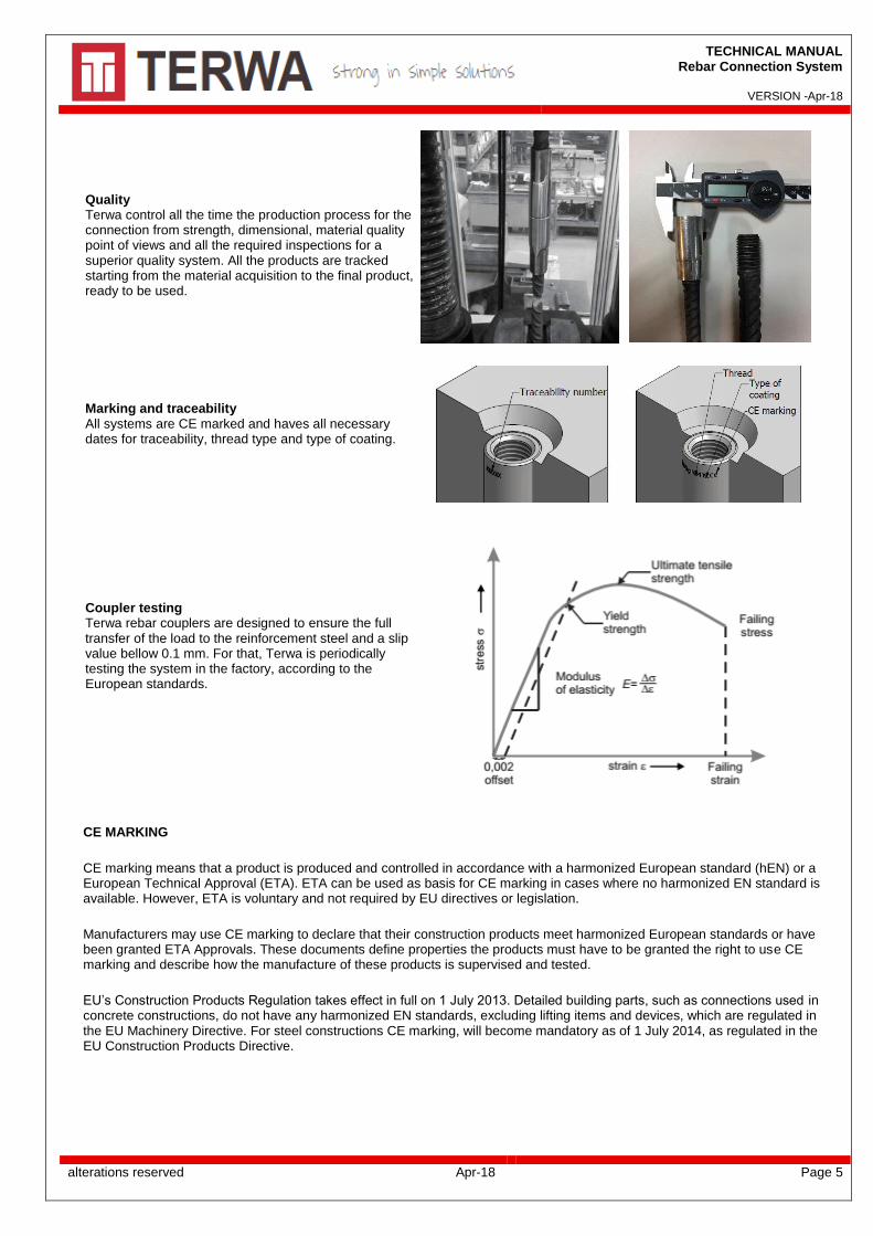
Quality Terwa control all the time the production process for the connection from strength, dimensional, material quality point of views and all the required inspections for a superior quality system. All the products are tracked starting from the material acquisition to the final product, ready to be used.
Marking and traceability All systems are CE marked and haves all necessary dates for traceability, thread type and type of coating.
Coupler testing Terwa rebar couplers are designed to ensure the full transfer of the load to the reinforcement steel and a slip value bellow 0.1 mm. For that, Terwa is periodically testing the system in the factory, according to the European standards.
CE MARKING
CE marking means that a product is produced and controlled in accordance with a harmonized European standard (hEN) or a European Technical Approval (ETA). ETA can be used as basis for CE marking in cases where no harmonized EN standard is available. However, ETA is voluntary and not required by EU directives or legislation.
Manufacturers may use CE marking to declare that their construction products meet harmonized European standards or have been granted ETA Approvals. These documents define properties the products must have to be granted the right to use CE marking and describe how the manufacture of these products is supervised and tested.
EU’s Construction Products Regulation takes effect in full on 1 July 2013. Detailed building parts, such as connections used in concrete constructions, do not have any harmonized EN standards, excluding lifting items and devices, which are regulated in the EU Machinery Directive. For steel constructions CE marking, will become mandatory as of 1 July 2014, as regulated in the EU Construction Products Directive.

TECHNICAL MANUAL Rebar Connection System
VERSION -Apr-18
alterations reserved Apr-18 Page 6
PSA REINFORCEMENT COUPLER
The reinforcement coupler PSA is composed of a reinforcement steel and a sleeve with interior metric thread pressed at one end.
In connection with a reinforcement coupler TSE or PSA-PSC, the coupler PSA ensures an uninterrupted reinforcement for all
types of precast concrete units. These couplers can be made at different dimensions.
These reinforcement couplers can also be used to lift and move the precast concrete elements.
The PKB couplers are made of steel 20CrMo5 or equivalent, electrolytic galvanized. These couplers are marked with the company
logo and the thread type. The reinforcement steel is standard B500B or B500C acc. to EN 10080 and BS4449.
On request the PKB couplers can be produced of stainless steel or hot zinc coating.
PSA Bush diameter Bush length Rebar diameter Thread
Description Product range no. D l d Metric A
[mm] [mm] [mm] M [mm]
PSA 10 - M12 - L 90117 17.5 50 10 12 18
PSA 12 - M16 - L 90012 22 62 12 16 25
PSA 14 - M18 - L 90638 26 74 14 18 32
PSA 16 - M20 - L 90013 28 86 16 20 38
PSA 18 - M22 - L 91248 31 92 18 22 40
PSA 20 - M24 - L 90014 34 99 20 24 42
PSA 22 - M27 - L 91246 36 107 22 27 45
PSA 25 - M30 - L 90015 40 117 25 30 52
PSA 28 - M36 - L 90572 50 130 28 36 55
PSA 32 - M42 - L 90016 54 153 32 42 65
PSA 40 - M48 - L 90175 65 188 40 48 72
Different length available on request: PSA – diam. d - thread x length (L) in mm.
TECHNICAL MANUAL Rebar Connection System
VERSION -Apr-18
alterations reserved Apr-18 Page 7
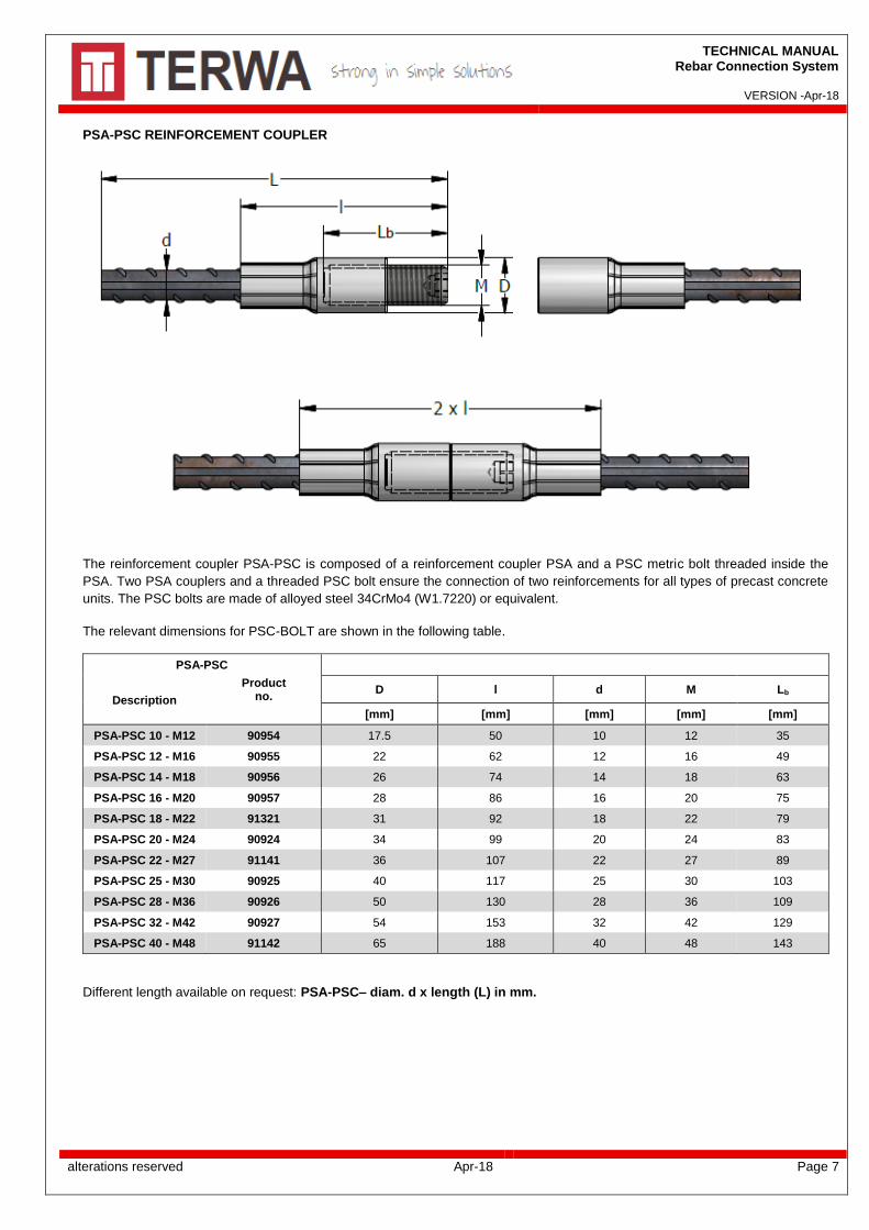
PSA-PSC REINFORCEMENT COUPLER
The reinforcement coupler PSA-PSC is composed of a reinforcement coupler PSA and a PSC metric bolt threaded inside the
PSA. Two PSA couplers and a threaded PSC bolt ensure the connection of two reinforcements for all types of precast concrete
units. The PSC bolts are made of alloyed steel 34CrMo4 (W1.7220) or equivalent.
The relevant dimensions for PSC-BOLT are shown in the following table.
PSA-PSC
Description
Product no.
D l d M Lb
[mm] [mm] [mm] [mm] [mm]
PSA-PSC 10 - M12 90954 17.5 50 10 12 35
PSA-PSC 12 - M16 90955 22 62 12 16 49
PSA-PSC 14 - M18 90956 26 74 14 18 63
PSA-PSC 16 - M20 90957 28 86 16 20 75
PSA-PSC 18 - M22 91321 31 92 18 22 79
PSA-PSC 20 - M24 90924 34 99 20 24 83
PSA-PSC 22 - M27 91141 36 107 22 27 89
PSA-PSC 25 - M30 90925 40 117 25 30 103
PSA-PSC 28 - M36 90926 50 130 28 36 109
PSA-PSC 32 - M42 90927 54 153 32 42 129
PSA-PSC 40 - M48 91142 65 188 40 48 143
Different length available on request: PSA-PSC– diam. d x length (L) in mm.

TECHNICAL MANUAL Rebar Connection System
VERSION -Apr-18
alterations reserved Apr-18 Page 8
TSE REINFORCEMENT COUPLER The reinforcement coupler TSE is produced of reinforcement steel standard B450C, B500B or B500C acc. to EN 10080 and BS4449, forged at one end and then metric thread rolled. The end diameter is increased more than the rebar diameter to grow the strength of the thread for tensile and shear loads.
TSE d
THREAD
Description Product range no. Metric A
[mm] [mm]
TSE 12 - M16 - L 90006 12 16 min 23
TSE 16 - M20 - L 90007 16 20 min 30
TSE 20 - M24 - L 90008 20 24 min 38
TSE 25 - M30 - L 90009 25 30 min 44
TSE 28 – M36 - L 91068 28 36 min 48
TSE 32 - M42 - L 90010 32 42 min 54
To connect with a reinforcement coupler PSA, the TSE coupler is screwed in PKB coupler on the entire length of thread. Different length available on request: TSE– diam. d – thread x length (L) in mm.
SPECIAL REINFORCEMENT COUPLERS
PSA-SS REINFORCEMENT COUPLER The reinforcement coupler PSA-SS is composed of a reinforcement coupler TSE and a stainless-steel KB bush.
PSA - SS Coupler
Description Product
no.
Thread A D
M [mm] [mm]
PSA - SS - M16 - L 45823 16 27 22
PSA - SS - M20 - L 45813 20 32 26
PSA - SS - M24 - L 45803 24 37 32
PSA - SS - M30 - L 45797 30 47 40

TECHNICAL MANUAL Rebar Connection System
VERSION -Apr-18
alterations reserved Apr-18 Page 9
PSA – REINFORCEMENT COUPLER WITH PROTECTION DISK
The reinforcement coupler PSA-WITH PROTECTION DISK is composed of a reinforcement coupler PSA and a stainless-steel disk pressed inside used to prevention of corrosion.
PSA - St sheet Coupler
Description Product
no.
Thread A D
M [mm] [mm]
PSA - St sheet 16 - M20 - L 91157 20 32 28
PSA - St sheet 20 - M27 - L 91158 27 37 36
PSA - St sheet 22 - M30 - L 91159 30 47 40
PSA - St sheet 28 - M36 - L 91187 36 47 50
Different length available on request: PSA-St sheet – diam. d - thread x length (L) in mm.
PSAD - DOUBLE REINFORCEMENT COUPLERS
The double reinforcement coupler PSAD is composed of reinforcement steel with two sleeves pressed at both ends. The
reinforcement steel is standard B450C, B500B or B500C acc. to EN 10080 and BS4449.
In table are presented some examples of these products.
PSAD Bush diameter Bush length Rebar diameter Thread
Description Product range no. D l d Metric A
[mm] [mm] [mm] [mm] [mm]
PSAD 10 - M12 - L 91132 17.5 50 10 12 18
PSAD 12 - M16 - L 90518 22 62 12 16 25
PSAD 14 - M18 - L 90651 26 74 14 18 32
PSAD 16 – M20 - L 90519 28 86 16 20 38
PSAD 20 – M24 - L 90520 34 99 20 24 42
PSAD 25 – M30 - L 90620 40 117 25 30 52
PSAD 28 – M36 - L 91131 50 130 28 36 55
PSAD 32 – M42 - L 90764 54 153 32 42 65
Different length available on request: PSAD – diam. d - thread x length (L) in mm.
TECHNICAL MANUAL Rebar Connection System
VERSION -Apr-18
alterations reserved Apr-18 Page 10
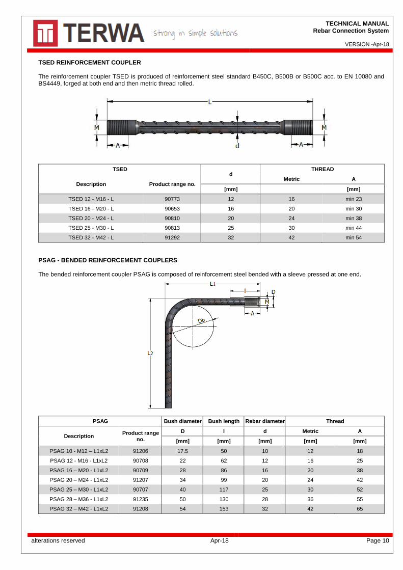
TSED REINFORCEMENT COUPLER The reinforcement coupler TSED is produced of reinforcement steel standard B450C, B500B or B500C acc. to EN 10080 and BS4449, forged at both end and then metric thread rolled.
TSED d
THREAD
Description Product range no. Metric A
[mm] [mm]
TSED 12 - M16 - L 90773 12 16 min 23
TSED 16 - M20 - L 90653 16 20 min 30
TSED 20 - M24 - L 90810 20 24 min 38
TSED 25 - M30 - L 90813 25 30 min 44
TSED 32 - M42 - L 91292 32 42 min 54
PSAG - BENDED REINFORCEMENT COUPLERS The bended reinforcement coupler PSAG is composed of reinforcement steel bended with a sleeve pressed at one end.
PSAG Bush diameter Bush length Rebar diameter Thread
Description Product range
no.
D l d Metric A
[mm] [mm] [mm] [mm] [mm]
PSAG 10 - M12 – L1xL2 91206 17.5 50 10 12 18
PSAG 12 - M16 - L1xL2 90708 22 62 12 16 25
PSAG 16 – M20 - L1xL2 90709 28 86 16 20 38
PSAG 20 – M24 - L1xL2 91207 34 99 20 24 42
PSAG 25 – M30 - L1xL2 90707 40 117 25 30 52
PSAG 28 – M36 - L1xL2 91235 50 130 28 36 55
PSAG 32 – M42 - L1xL2 91208 54 153 32 42 65

TECHNICAL MANUAL Rebar Connection System
VERSION -Apr-18
alterations reserved Apr-18 Page 11
The PSAG coupler, generally have the bend diameter DB= 10 x d, but this can be produced on request with DB= 15 x d or DB= 20 x d. Also, other length L1 and L2 available on request: PSAG d x Length L1x L2 in mm. For choosing dimensions L1 and L2 should take into account the minimum size according with the table below. L1 is the length measured from the front of coupler to the back of the reinforcing bar. The minimum dimensions for bending are presented in the following table. The diameter to which a bar is bent should be such as
to avoid damage to the reinforcement and crushing of concrete inside the bend of the bar. According to Eurocode 2 minimum
bending diameter should be:
• DBmin = 4 x d for bar diameter d ≤ 16mm
• DBmin = 7 x d for bar diameter d > 16mm
Reinforcing diameter “d”
Thread L1 min L2 min Bending diameter
DB min
[mm] M [mm] [mm] [mm]
12 M16 160 125 48 4 x d
16 M20 210 130 64
20 M24 230 190 140
7 x d 25 M30 300 240 175
32 M42 370 325 224
The length for the bended reinforcement coupler can be calculated with the formula:
L = L1 + L2 – x, for a single bend
L = L1 + L2 +L1 – 2x for double bends
x = (DB + 2d) – y “y” is the length in bending area, ‘’x’’ deduction of the bar length due to bending
‘’x’’ deduction of the bar length due to
bending
Reinforcing bar diameter d (mm)
12 16 20 25 32
Bending diameter DB mm
4 x d 25 33 - - -
7 x d 33 44 54 68 87
10 x d 40 54 67 84 108
15 x d 53 71 89 111 142
20 x d 66 88 110 138 176
Bending angle = 90°
PSAG – d x L1 x L2 - TYPE 1 TSEG – d x L1 x L2 - TYPE 1
TECHNICAL MANUAL Rebar Connection System
VERSION -Apr-18
alterations reserved Apr-18 Page 12
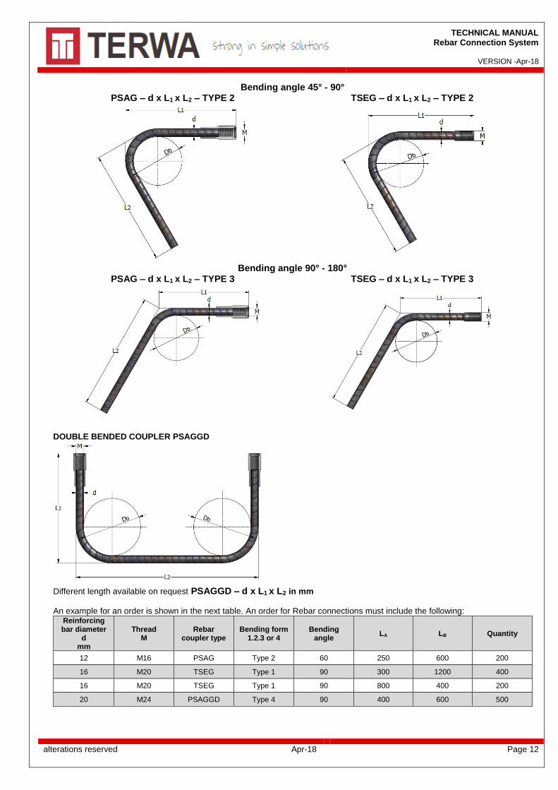
Bending angle 45° - 90° PSAG – d x L1 x L2 – TYPE 2 TSEG – d x L1 x L2 – TYPE 2
Bending angle 90° - 180°
PSAG – d x L1 x L2 – TYPE 3 TSEG – d x L1 x L2 – TYPE 3
DOUBLE BENDED COUPLER PSAGGD
Different length available on request PSAGGD – d x L1 x L2 in mm
An example for an order is shown in the next table. An order for Rebar connections must include the following:
Reinforcing bar diameter
d mm
Thread M
Rebar coupler type
Bending form 1.2.3 or 4
Bending angle
LA LB Quantity
12 M16 PSAG Type 2 60 250 600 200
16 M20 TSEG Type 1 90 300 1200 400
16 M20 TSEG Type 1 90 800 400 200
20 M24 PSAGGD Type 4 90 400 600 500

TECHNICAL MANUAL Rebar Connection System
VERSION -Apr-18
alterations reserved Apr-18 Page 13
PSA-T TRANSITION COUPLERS
The reinforcement coupler PSA-T is composed of a reinforcement steel and a special sleeve with interior metric thread pressed at one end. The connection is realized between two rebar with different diameter, second rebar can be rotated and is not restricted in its axial direction. The connection with a reinforcement coupler TSE or a PSC bolt and a PSA the coupler PSA-T ensures an uninterrupted reinforcement for all types of precast concrete units. Different length available on request: PSA-T – diam. d1/d2 – thread x length (L) in mm.
PSA-T Rebar diameter Sleeve dimensions
Description Product range
no.
First rebar d1 Second rebar d2 D l1 A
[mm] [mm] [mm] [mm] [mm]
PSA-T 16/12 - M16 - L 91299 16 12 28 39 25
PSA-T 16/14 - M18 - L 91300 16 14 28 39 32
PSA-T 18/14 - M18 - L 91301 18 14 31 41 32
PSA-T 18/16 - M20 - L 91302 18 16 31 41 38
PSA-T 20/16 - M20 - L 91303 20 16 34 43 38
PSA-T 20/18 - M22 - L 91304 20 18 34 43 40
PSA-T 22/14 - M18 - L 91305 22 14 36 49 32
PSA-T 22/16 - M20 - L 91306 22 16 36 49 38
PSA-T 22/20 - M24 - L 91307 22 20 36 49 42
PSA-T 25/14 - M18 - L 91308 25 14 40 53 32
PSA-T 25/16 - M20 - L 91309 25 16 40 53 38
PSA-T 25/20 - M24 - L 91310 25 20 40 53 42
PSA-T 28/16 - M20 - L 91311 28 16 50 56 38
PSA-T 28/20 - M24 - L 91312 28 20 50 56 42
PSA-T 28/22 - M27 - L 91382 28 22 50 56 45
PSA-T 28/25 - M30 - L 91313 28 25 50 56 52
PSA-T 32/20 - M24 - L 91314 32 20 54 75 42
PSA-T 32/25 - M30 - L 91315 32 25 54 75 52
PSA-T 32/28 - M36 - L 91316 32 28 54 75 56
PSA-T 40/25 - M30 - L 91317 40 25 65 97 52
PSA-T 40/28 - M36 - L 91318 40 28 65 97 56
PSA-T 40/32 - M42 - L 91319 40 32 65 97 65

TECHNICAL MANUAL Rebar Connection System
VERSION -Apr-18
alterations reserved Apr-18 Page 14
INSTRUCTIONS FOR INSTALLING PSA-T COUPLER
Place in and rotate the TSE or PSA-PSC coupler into the PSA-T cupler.
The connection is finished by using a special torque wrench made by TERWA to tighten the connection. The connection must be sufficiently tight to prevent movement during concrete placement. The necessary torque for each type of rebar is shown in table at page 23.
PSA-T – TSE connection
PSA-T – PSA-PSC connection

TECHNICAL MANUAL Rebar Connection System
VERSION -Apr-18
alterations reserved Apr-18 Page 15
TERWA END COUPLERS
The Terwa End Coupler represents an efficient alternative for the traditional connections roof-column, beam-column or foundation-column.
TERWA END COUPLER CLASSIC SOLUTION
The End Coupler it is highlighted by the next advantages:
• Minimize the length of the rebar and reduce the
congestion inside the concrete element;
• Eliminate the hooks;
• Faster and simple installation;
• Simplifies the structural design;
• Better anchorage in the concrete element.
The traditional method consists in a hooked rebar anchorage
who comes with a series of disadvantages:
• Requires longer lengths of anchorage which
increase rebar congestion;
• More labor for the installation;
• Longer time for execution;
• Hidden costs, especially for bigger diameters (the
lap length grow proportional with the reinforcement
steel diameter);
• Lower safety on construction sites.
Column Connection
Foundation Connection
Terwa End Coupler consists in a threaded round steel plate which fits with PSA-PSC connection or with TSE connection.
Terwa End Couplers meets the ACI 318 and Eurocode 2 regarding the embedding lengths for reinforcement steel. The End Coupler is designed and tested to assure a good embedding in concrete having a contact area equal with 9 times the rebar cross section area, or a minimum diameter 3 times the rebar diameter.

TECHNICAL MANUAL Rebar Connection System
VERSION -Apr-18
alterations reserved Apr-18 Page 16
Beam – Column Connection
PSA END COUPLER TSE END COUPLER Terwa End Couplers are available electrolytic galvanized or without coating.
End Coupler
Product no. Thread Thickness
A D
Rebar diameter (d)
Weight
Electrolytic galvanised
EV
Without coating
Metric [mm] [mm] [mm] [kg/pc]
End coupler M12 61614 61556 M12 10 38 10 0.084
End coupler M16 61615 61557 M16 12 45 12 0.137
End coupler M20 61616 61558 M20 18 60 16 0.369
End coupler M24 61617 61613 M24 20 75 20 0.644
End coupler M30 61618 61560 M30 27 90 25 1.231
End coupler M36 61619 61561 M36 30 105 28 1.850
End coupler M42 61620 61562 M42 35 120 32 2.804
End coupler M48 61621 61563 M48 40 145 40 4.729

TECHNICAL MANUAL Rebar Connection System
VERSION -Apr-18
alterations reserved Apr-18 Page 17
KB-W THREAD WELDABLE COUPLER
KB-W – is a KB bush used to connect reinforcing bars to structural steel plates or sections. The KB-W bush has a thread at one end. The other end is welded directly to the structural steel. The KB-W couplers are made of steel S355 or equivalent. The type and size of weld must be determined by the designer. Welders should be qualified for the type of weld required.
KB-W Weldable Coupler Product no. Thread L D A Weight
Metric [mm] [mm] [mm] [kg/pc]
KB-W M12 61792 M12 41 17.5 18 0.059
KB-W M16 61793 M16 50 22 26 0.104
KB-W M20 61794 M20 65 28 39 0.214
KB-W M24 61795 M24 76 34 43 0.382
KB-W M30 61796 M30 88 40 53 0.561
KB-W M36 61797 M36 94 50 56 0.963
KB-W M42 61798 M42 103 54 65 1.100
KB-W M48 61799 M48 115 65 74 1.854
TECHNICAL MANUAL Rebar Connection System
VERSION -Apr-18
alterations reserved Apr-18 Page 18
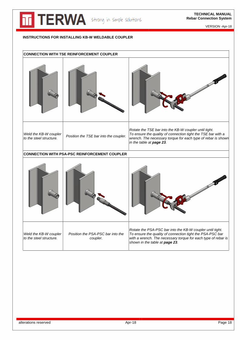
INSTRUCTIONS FOR INSTALLING KB-W WELDABLE COUPLER
CONNECTION WITH TSE REINFORCEMENT COUPLER
Weld the KB-W coupler to the steel structure.
Position the TSE bar into the coupler.
Rotate the TSE bar into the KB-W coupler until tight. To ensure the quality of connection tight the TSE bar with a wrench. The necessary torque for each type of rebar is shown in the table at page 23.
CONNECTION WITH PSA-PSC REINFORCEMENT COUPLER
Weld the KB-W coupler to the steel structure.
Position the PSA-PSC bar into the coupler.
Rotate the PSA-PSC bar into the KB-W coupler until tight. To ensure the quality of connection tight the PSA-PSC bar with a wrench. The necessary torque for each type of rebar is shown in the table at page 23.

TECHNICAL MANUAL Rebar Connection System
VERSION -Apr-18
alterations reserved Apr-18 Page 19
FIXING CONNECTOR – KB
Fixing connectors KB are manufactured of steel S355JO galvanized (EV), hot dipped galvanized (TV) or of stainless steel 304 / W 1.4301 (SS2) or W 1.4571 –AISI 316Ti (SS4).
KB
Product number Thread Overall length
L D Weight
Zinc galvanizing
Hot dipped galvanized
Stainless steel SS4
Stainless steel SS2
M [mm] [mm] [kg/pc]
KB M12x36 45662 45679 44342 44331 12 36 16 0.033
KB M16x48 45668 45678 44343 44653 16 48 22 0.085
KB M16x45 45902 45905 45904 45903 16 45 22 0.079
KB M20x55 45898 45901 45900 45899 20 55 26 0.124
KB M20x60 45663 45677 44345 44655 20 60 26 0.135
KB M24x72 45664 45676 44347 44335 24 72 32 0.257
KB M30x90 45665 45675 44471 44338 30 90 40 0.493
KB M36x110 45666 45674 44802 45542 36 110 47.5 0.830
KB M42x126 44468 44470 45537 44340 42 126 54 1.166
FIXING CONNECTOR – KBL
Fixing connectors KBL are manufactured of steel S355JO (EN 10025) galvanized (EV) or of stainless steel W 1.4571 –AISI 316Ti (SS4).
KBL
Product number Thread Overall length L D Weight
Zinc galvanizing Stainless steel
SS4 M [mm] [mm] [kg/pc]
KBL M12x45 45835 45840 12 36 16 0.042
KBL M16x45 60863 47668 16 48 22 0.081
KBL M16x60 45836 45841 16 45 22 0.108
KBL M20x55 47669 20 55 26 0.127
KBL M20x75 45837 45842 20 60 26 0.173
KBL M24x90 45838 45843 24 72 32 0.329
KBL M30x90 45839 45844 30 90 40 0.506
TECHNICAL MANUAL Rebar Connection System
VERSION -Apr-18
alterations reserved Apr-18 Page 20
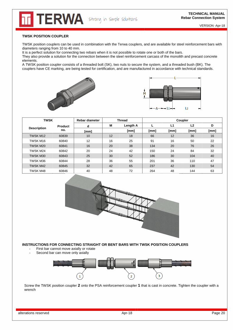
TWSK POSITION COUPLER TWSK position couplers can be used in combination with the Terwa couplers, and are available for steel reinforcement bars with diameters ranging from 10 to 40 mm. It is a perfect solution for connecting two rebars when it is not possible to rotate one or both of the bars. They also provide a solution for the connection between the steel reinforcement carcass of the monolith and precast concrete elements. A TWSK position coupler consists of a threaded bolt (SK), two nuts to secure the system, and a threaded bush (BK). The couplers have CE marking, are being tested for certification, and are manufactured in accordance with technical standards.
TWSK Rebar diameter Thread Coupler
Description Product
no.
d M Length A L L1 L2 D
[mm] [mm] [mm] [mm] [mm] [mm]
TWSK M12 60839 10 12 18 66 12 36 16
TWSK M16 60840 12 16 25 91 16 50 22
TWSK M20 60841 16 20 38 134 20 76 26
TWSK M24 60842 20 24 42 150 24 84 32
TWSK M30 60843 25 30 52 186 30 104 40
TWSK M36 60844 28 36 55 201 36 110 47
TWSK M42 60845 32 42 65 237 42 130 54
TWSK M48 60846 40 48 72 264 48 144 63
INSTRUCTIONS FOR CONNECTING STRAIGHT OR BENT BARS WITH TWSK POSITION COUPLERS
- First bar cannot move axially or rotate - Second bar can move only axially
Screw the TWSK position coupler 2 onto the PSA reinforcement coupler 1 that is cast in concrete. Tighten the coupler with a
wrench

TECHNICAL MANUAL Rebar Connection System
VERSION -Apr-18
alterations reserved Apr-18 Page 21
After the TWSK coupler 2 has been fixed onto the first PSA coupler 1, tighten the first locknut.
Arrange the second reinforcement coupler 3 (TSEG, TSE, or PSAG, PSA-PSC) for coupling with the TWSK coupler 2.
Screw the threaded bush onto the reinforcement coupler.
Tighten the locknut with a wrench to ensure the connection is secure.
1. Remove nailing plate from PSA coupler in the
concrete element 2. Hand-tighten the threaded bar in coupler PSA.
Tighten first nut of TWSK against PSA coupler.
3. Align the thread of PSA-PSC coupler. Turn the TWSK bush.
4. Tighten the second nut against the TWSK bush. The necessary torque for each type of rebar is shown at page 23.
TECHNICAL MANUAL Rebar Connection System
VERSION -Apr-18
alterations reserved Apr-18 Page 22
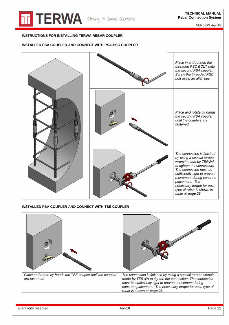
INSTRUCTIONS FOR INSTALLING TERWA REBAR COUPLER
INSTALLED PSA COUPLER AND CONNECT WITH PSA-PSC COUPLER
Place in and rotated the threaded PSC BOLT onto the second PSA coupler. Screw the threaded PSC bolt using an allen key.
Place and rotate by hands the second PSA coupler until the couplers are fastened.
The connection is finished by using a special torque wrench made by TERWA to tighten the connection. The connection must be sufficiently tight to prevent movement during concrete placement. The necessary torque for each type of rebar is shown in table at page 23.
INSTALLED PSA COUPLER AND CONNECT WITH TSE COUPLER
Place and rotate by hands the TSE coupler until the couplers are fastened.
The connection is finished by using a special torque wrench made by TERWA to tighten the connection. The connection must be sufficiently tight to prevent movement during concrete placement. The necessary torque for each type of rebar is shown at page 23.

TECHNICAL MANUAL Rebar Connection System
VERSION -Apr-18
alterations reserved Apr-18 Page 23
TERWA TORQUE WRENCH Terwa Torque wrench is specially designed for a correct mounting of the Terwa coupler on site and in the factories. All Terwa wrenches are delivered together with a calibration report and work instructions. The torque values are marked on the wrench for all diameters of rebar. The torque values for all Terwa couplers are highlighted bellow.
Reinforcement diameter [mm]
Necessary Torque for each type of rebar [Nm]
Setting torque by wrench Mt [Nm]
10 50 60
12 60 60
14 70 60
16 80 60
18 90 70
20 100 75
22 110 82
25 125 93
28 140 104
32 160 119
40 200 148
TERWA torque wrench
Mn – needed torque Mt – Torque setting by wrench LP – length until each middle reinforcement steel LN – standard length wrench Mt = Mn x LN/LP
TERWA wrench dimensions
TECHNICAL MANUAL Rebar Connection System
VERSION -Apr-18
alterations reserved Apr-18 Page 24
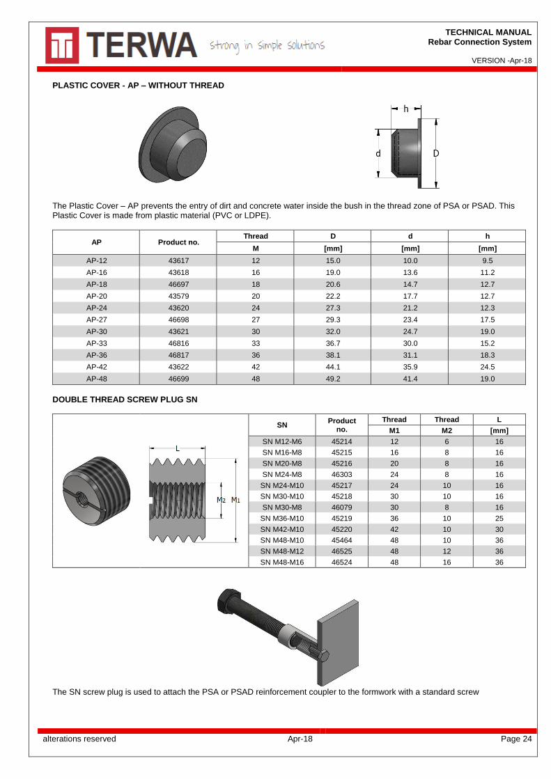
PLASTIC COVER - AP – WITHOUT THREAD
The Plastic Cover – AP prevents the entry of dirt and concrete water inside the bush in the thread zone of PSA or PSAD. This Plastic Cover is made from plastic material (PVC or LDPE).
AP Product no. Thread D d h
M [mm] [mm] [mm]
AP-12 43617 12 15.0 10.0 9.5
AP-16 43618 16 19.0 13.6 11.2
AP-18 46697 18 20.6 14.7 12.7
AP-20 43579 20 22.2 17.7 12.7
AP-24 43620 24 27.3 21.2 12.3
AP-27 46698 27 29.3 23.4 17.5
AP-30 43621 30 32.0 24.7 19.0
AP-33 46816 33 36.7 30.0 15.2
AP-36 46817 36 38.1 31.1 18.3
AP-42 43622 42 44.1 35.9 24.5
AP-48 46699 48 49.2 41.4 19.0
DOUBLE THREAD SCREW PLUG SN
SN Product
no.
Thread Thread L
M1 M2 [mm]
SN M12-M6 45214 12 6 16
SN M16-M8 45215 16 8 16
SN M20-M8 45216 20 8 16
SN M24-M8 46303 24 8 16
SN M24-M10 45217 24 10 16
SN M30-M10 45218 30 10 16
SN M30-M8 46079 30 8 16
SN M36-M10 45219 36 10 25
SN M42-M10 45220 42 10 30
SN M48-M10 45464 48 10 36
SN M48-M12 46525 48 12 36
SN M48-M16 46524 48 16 36
The SN screw plug is used to attach the PSA or PSAD reinforcement coupler to the formwork with a standard screw
TECHNICAL MANUAL Rebar Connection System
VERSION -Apr-18
alterations reserved Apr-18 Page 25
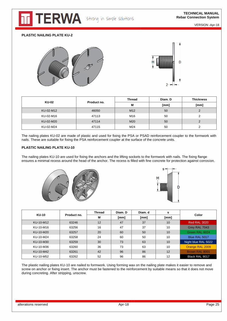
PLASTIC NAILING PLATE KU-2
KU-02 Product no. Thread Diam. D Thickness
M [mm] [mm]
KU-02-M12 46050 M12 50 2
KU-02-M16 47113 M16 50 2
KU-02-M20 47114 M20 50 2
KU-02-M24 47115 M24 50 2
The nailing plates KU-02 are made of plastic and used for fixing the PSA or PSAD reinforcement coupler to the formwork with nails. These are suitable for fixing the PSA reinforcement coupler at the surface of the concrete units. PLASTIC NAILING PLATE KU-10
The nailing plates KU-10 are used for fixing the anchors and the lifting sockets to the formwork with nails. The fixing flange ensures a minimal recess around the head of the anchor. The recess is filled with fine concrete for protection against corrosion.
KU-10 Product no. Thread Diam. D Diam. d s
Color M [mm] [mm] [mm]
KU-10-M12 63246 12 47 37 10 Red RAL 3020
KU-10-M16 63256 16 47 37 10 Grey RAL 7043
KU-10-M20 63257 20 60 50 10 Green RAL 6024
KU-10-M24 63258 24 60 50 10 Blue RAL 5017
KU-10-M30 63259 30 73 63 10 Night blue RAL 5022
KU-10-M36 63260 36 73 63 10 Orange RAL 2009
KU-10-M42 63261 42 96 86 12 Brown RAL 8001
KU-10-M52 63262 52 96 86 12 Black RAL 9017
The plastic nailing plates KU-10 are nailed to formwork. Using forming wax on the nailing plate makes it easier to remove and screw on anchor or fixing insert. The anchor must be fastened to the reinforcement by suitable means so that it does not move during concreting. After stripping, unscrew.
TECHNICAL MANUAL Rebar Connection System
VERSION -Apr-18
alterations reserved Apr-18 Page 26
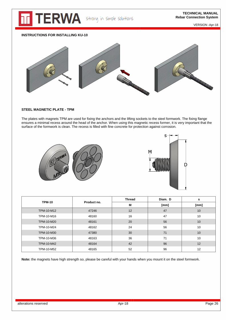
INSTRUCTIONS FOR INSTALLING KU-10
STEEL MAGNETIC PLATE - TPM
The plates with magnets TPM are used for fixing the anchors and the lifting sockets to the steel formwork. The fixing flange ensures a minimal recess around the head of the anchor. When using this magnetic recess former, it is very important that the surface of the formwork is clean. The recess is filled with fine concrete for protection against corrosion.
TPM-10 Product no. Thread Diam. D s
M [mm] [mm]
TPM-10-M12 47246 12 47 10
TPM-10-M16 48160 16 47 10
TPM-10-M20 48161 20 56 10
TPM-10-M24 48162 24 56 10
TPM-10-M30 47380 30 71 10
TPM-10-M36 48163 36 71 10
TPM-10-M42 48164 42 96 12
TPM-10-M52 48165 52 96 12
Note: the magnets have high strength so, please be careful with your hands when you mount it on the steel formwork.

TECHNICAL MANUAL Rebar Connection System
VERSION -Apr-18
alterations reserved Apr-18 Page 27
ALL SPECIFICATIONS CAN BE CHANGED WITHOUT PREVIOUS NOTICE.
DISCLAIMER
Terwa B.V. is not liable for deviations to the products delivered by her caused by wear. Terwa B.V. is also not liable for damage caused by inaccurate and/or injudicious handling and use of the products delivered by her and/or use of these for purposes for which they are not produced. The responsibility of Terwa B.V. is furthermore limited in conformity to article 13 of the “Metaalunie” conditions, conditions which are applicable for all deliveries of Terwa B.V. Complying with all applicable copyright laws is the responsibility of the user. Without limiting the rights under copyright, no part of this documentation may be reproduced, stored in or introduced into a retrieval system, or transmitted in any form or by any means (electronic, mechanical, photocopying, recording, or otherwise), or for any purpose, without the express written permission of Terwa B.V.


![ICC-ES Evaluation Report ESR-4019 Issued January 2020 This ...8316].pdf · B500B or equivalent ASTM A615 / A706 with yield strength ≥500 N/mm² (72,519 psi). Design values of reinforcing](https://static.fdocuments.us/doc/165x107/5e80a436dedba45d3e2d6d72/icc-es-evaluation-report-esr-4019-issued-january-2020-this-8316pdf-b500b.jpg)


