RealView Emulation Baseboard Real-Time System Model User...
96
Copyright © 2008 ARM Limited. All rights reserved. ARM DUI0424B RealView ® Emulation Baseboard Real-Time System Model Rev 1.1 User Guide
Transcript of RealView Emulation Baseboard Real-Time System Model User...

RealView® Emulation BaseboardReal-Time System Model
Rev 1.1
User Guide
Copyright © 2008 ARM Limited. All rights reserved.ARM DUI0424B

RealView Emulation Baseboard Real-Time System ModelUser Guide
Copyright © 2008 ARM Limited. All rights reserved.
Release Information
Proprietary Notice
Words and logos marked with® or ™ are registered trademarks or trademarks owned by ARM Limited, except as otherwise stated below in this proprietary notice. Other brands and names mentioned herein may be the trademarks of their respective owners.
Neither the whole nor any part of the information contained in, or the product described in, this document may be adapted or reproduced in any material form except with the prior written permission of the copyright holder.
The product described in this document is subject to continuous developments and improvements. All particulars of the product and its use contained in this document are given by ARM in good faith. However, all warranties implied or expressed, including but not limited to implied warranties of merchantability, or fitness for purpose, are excluded.
This document is intended only to assist the reader in the use of the product. ARM Limited shall not be liable for any loss or damage arising from the use of any information in this document, or any error or omission in such information, or any incorrect use of the product.
Confidentiality Status
This document is Non-Confidential. The right to use, copy and disclose this document may be subject to license restrictions in accordance with the terms of the agreement entered into by ARM and the party that ARM delivered this document to.
Unrestricted Access is an ARM internal classification.
Product Status
The information in this document is final, that is for a developed product.
Web Address
http://www.arm.com
Change history
Description Issue Confidentiality Change
August 2008 A Non-Confidential Release 1.0 for RealView Development Suite v4.0 Professional, System Generator v4.0 SP1.
December 2008 B Confidential - Draft Release 1.1 for Fast Models 4.1. Added changes related to ARM_RTSM_PATH.
ii Copyright © 2008 ARM Limited. All rights reserved. ARM DUI0424BNon-Confidential Unrestricted Access

ContentsRealView Emulation Baseboard Real-Time System Model User Guide
PrefaceAbout this book .............................................................................................. xFeedback ..................................................................................................... xiv
Chapter 1 Introduction1.1 About the Emulation Baseboard ................................................................. 1-21.2 About the Emulation Baseboard Real-Time System Models ...................... 1-3
Chapter 2 Getting Started2.1 Getting started with System Canvas for Fast Models ................................. 2-22.2 Getting started with ARM Profiler ................................................................ 2-72.3 Getting started with RealView Debugger .................................................... 2-82.4 Configuring the EB Real-Time System Model ........................................... 2-112.5 Loading and running an application .......................................................... 2-142.6 Using the CLCD window ........................................................................... 2-19
Chapter 3 Programmer’s Reference3.1 Memory map ............................................................................................... 3-23.2 Model configuration parameters .................................................................. 3-63.3 Differences between the EB hardware and the system model ................. 3-27
ARM DUI0424B Copyright © 2008 ARM Limited. All rights reserved. iiiUnrestricted Access Non-Confidential
Contents
Chapter 4 Using Model Components4.1 Terminal ...................................................................................................... 4-24.2 Ethernet ...................................................................................................... 4-54.3 Virtual filesystem ...................................................................................... 4-12
Glossary
iv Copyright © 2008 ARM Limited. All rights reserved. ARM DUI0424BNon-Confidential Unrestricted Access

List of TablesRealView Emulation Baseboard Real-Time System Model User Guide
Change history .............................................................................................................. iiTable 3-1 Memory map and interrupts for standard peripherals ............................................... 3-2Table 3-2 EBBaseboard Model instantiation parameters .......................................................... 3-7Table 3-3 Default positions for EB System Model switch S6 .................................................... 3-8Table 3-4 STDIO redirection ..................................................................................................... 3-8Table 3-5 EB System Model switch S8 settings ........................................................................ 3-9Table 3-6 Ethernet instantiation parameters ........................................................................... 3-10Table 3-7 UART instantiation parameters ............................................................................... 3-11Table 3-8 Terminal instantiation parameters ........................................................................... 3-12Table 3-9 Visualisation instantiation parameters ..................................................................... 3-13Table 3-10 Profiler instantiation parameters ............................................................................. 3-14Table 3-11 ARMCortexA9MPCT RTSM parameters ................................................................. 3-15Table 3-12 ARMCortexA9MPCT RTSM individual core parameters ......................................... 3-16Table 3-13 ARMCortexA8CT RTSM parameters ...................................................................... 3-18Table 3-14 ARMCortexR4CT RTSM parameters ...................................................................... 3-20Table 3-15 ARM1176CT RTSM parameters ............................................................................. 3-22Table 3-16 ARM1136CT RTSM parameters ............................................................................. 3-24Table 3-17 ARM926CT RTSM parameters ............................................................................... 3-26
ARM DUI0424B Copyright © 2008 ARM Limited. All rights reserved. vUnrestricted Access Non-Confidential

List of Tables
vi Copyright © 2008 ARM Limited. All rights reserved. ARM DUI0424BNon-Confidential Unrestricted Access

List of FiguresRealView Emulation Baseboard Real-Time System Model User Guide
Figure 1-1 Top-level model as implemented by System Canvas ............................................... 1-5Figure 1-2 ARM1176 Core Tile model as implemented by System Canvas ............................... 1-6Figure 1-3 EB Baseboard model as implemented by System Canvas ....................................... 1-7Figure 2-1 Model Debugger Connect remote dialog .................................................................. 2-5Figure 2-2 Model Debugger Select Targets dialog ..................................................................... 2-6Figure 2-3 Configure Model Parameters dialog ........................................................................ 2-12Figure 2-4 CLCD window ......................................................................................................... 2-15Figure 2-5 ARM Profiler Run dialog .......................................................................................... 2-16Figure 2-6 ARM Profiler analysis .............................................................................................. 2-17Figure 2-7 Breakpoint in brot.c ................................................................................................. 2-18Figure 2-8 CLCD window at startup ......................................................................................... 2-19Figure 2-9 CLCD window alternative display ............................................................................ 2-21Figure 4-1 Terminal block diagram ............................................................................................. 4-3Figure 4-2 Host transport block diagram .................................................................................... 4-8Figure 4-3 Pipe transport block diagram .................................................................................... 4-9
ARM DUI0424B Copyright © 2008 ARM Limited. All rights reserved. viiUnrestricted Access Non-Confidential

List of Figures
viii Copyright © 2008 ARM Limited. All rights reserved. ARM DUI0424BNon-Confidential Unrestricted Access

Preface
This preface introduces the RealView® Emulation Baseboard Real-Time System Model User Guide. It contains the following sections:
• About this book on page x
• Feedback on page xiv.
ARM DUI0424B Copyright © 2008 ARM Limited. All rights reserved. ixUnrestricted Access Non-Confidential

Preface
About this book
This book describes how to configure and use the RealView Emulation Baseboard Real-Time System Models (EB RTSM). The models let you run software applications on a virtual implementation of a RealView Emulation Baseboard and an attached Core Tile.
Intended audience
This book has been written for experienced hardware and software developers to understand how the EB RTSM example is constructed, and to aid the development of ARM®-based products using the EB RTSMs as part of a development environment.
Organization
This book is organized into the following chapters:
Chapter 1 Introduction
Read this chapter for an introduction to the EB hardware and the corresponding system model. This chapter shows the physical layout of the model and identifies the main components.
Chapter 2 Getting Started
Read this chapter for a description of how to start using the EB Real-Time System Models.
Chapter 3 Programmer’s Reference
Read this chapter for a description of the baseboard memory map and registers, as well as information on model parameters and component configuration. This chapter describes differences between the Real-Time System Models and their hardware equivalents.
Chapter 4 Using Model Components
Read this chapter for detailed information on the Terminal, Ethernet and Virtual File System features provided with the EB Real-Time System Models.
Glossary Read the Glossary for definitions of terms used in this book.
x Copyright © 2008 ARM Limited. All rights reserved. ARM DUI0424BNon-Confidential Unrestricted Access

Preface
Typographical conventions
The typographical conventions are:
italic Highlights important notes, introduces special terminology, denotes internal cross-references, and citations.
bold Highlights interface elements, such as menu names. Denotes signal names. Also used for terms in descriptive lists, where appropriate.
monospace Denotes text that you can enter at the keyboard, such as commands, file and program names, and source code.
monospace Denotes a permitted abbreviation for a command or option. You can enter the underlined text instead of the full command or option name.
monospace italic Denotes arguments to monospace text where the argument is to be replaced by a specific value.
monospace bold Denotes language keywords when used outside example code.
< and > Enclose replaceable terms for assembler syntax where they appear in code or code fragments. For example:
MRC p15, 0 <Rd>, <CRn>, <CRm>, <Opcode_2>
Further reading
This section lists publications by ARM and by third parties.
See http://infocenter.arm.com/ for access to ARM documentation.
ARM publications
This book contains information that is specific to this product. The following publications provide reference information about the ARM architecture:
• AMBA® Specification (ARM IHI 0011)
• ARM Architecture Reference Manual (ARM DDI 0100).
The following publications provide information about related ARM products and toolkits:
• RealView Emulation Baseboard User Guide (Lead Free) (ARM DUI 0411)
• Fast Model Portfolio Emulation Baseboard Components Reference Manual (ARM DUI 0428)
ARM DUI0424B Copyright © 2008 ARM Limited. All rights reserved. xiUnrestricted Access Non-Confidential
Preface
• Fast Model Portfolio Integrator® Components Reference Manual (ARM DUI 0419)
• Fast Model Portfolio Peripheral Components Reference Manual (ARM DUI 0423)
• Fast Model Portfolio CT Core Components Reference Manual (ARM DUI 0426)
• ARM Cycle Accurate Debug Interface Developer’s Guide (ARM DUI 0444)
• Model Debugger for Fast Models User Guide (ARM DUI 0314)
• Fast Model Tools User Guide (ARM DUI 0370)
• ARM Profiler User Guide (ARM DUI 0412)
• RealView Debugger Essentials Guide (ARM DUI 0181)
• RealView Debugger User Guide (ARM DUI 0153)
• RealView Debugger Target Configuration Guide (ARM DUI 0182).
The following publications provide information about ARM PrimeCell® and other peripheral or controller devices:
• ARM PrimeCell UART (PL011) Technical Reference Manual (ARM DDI 0183)
• ARM PrimeCell Synchronous Serial Port Controller (PL022) Technical Reference Manual (ARM DDI 0194)
• ARM PrimeCell Real Time Clock Controller (PL031) Technical Reference Manual (ARM DDI 0224)
• ARM PrimeCell® Advanced Audio CODEC Interface (PL041) Technical Reference Manual (ARM DDI 0173)
• ARM PrimeCell GPIO (PL061) Technical Reference Manual (ARM DDI 0190)
• ARM PrimeCell DMA (PL081) Technical Reference Manual (ARM DDI 0196)
• ARM PrimeCell Synchronous Static Memory Controller (PL093) Technical Reference Manual (ARM DDI 236)
• ARM PrimeCell Color LCD Controller (PL111) Technical Reference Manual (ARM DDI 0161)
• ARM PrimeCell Smart Card Interface (PL131) Technical Reference Manual (ARM DDI 0228)
xii Copyright © 2008 ARM Limited. All rights reserved. ARM DUI0424BNon-Confidential Unrestricted Access
Preface
• ARM PrimeCell Multimedia Card Interface (PL180) Technical Reference Manual (ARM DDI 0172)
• ARM PrimeCell External Bus Interface (PL220) Technical Reference Manual (ARM DDI 0249)
• PrimeCell Level 2 Cache Controller (PL310) Technical Reference Manual (ARM DDI 0246)
• ARM Dynamic Memory Controller (PL340) Technical Reference Manual (ARM DDI 0331)
• PrimeCell Generic Interrupt Controller (PL390) Technical Reference Manual (ARM DDI 0416)
• ARM Dual-Timer Module (SP804) Technical Reference Manual (ARM DDI 0271)
• ARM PrimeCell Watchdog Controller (SP805) Technical Reference Manual (ARM DDI 0270)
• ARM PrimeCell System Controller (SP810) Technical Reference Manual (ARM DDI 0254).
Other publications
This section lists relevant documents published by third parties. The following data sheets describe some of the integrated circuits or modules used on the Emulation Baseboard:
• CODEC with Sample Rate Conversion and 3D Sound (LM4549) National Semiconductor, Santa Clara, CA.
• MultiMedia Card Product Manual SanDisk, Sunnyvale, CA.
• Serially Programmable Clock Source (ICS307), ICS, San Jose, CA.
• 1.8 Volt Intel StrataFlash Wireless Memory with 3.0 Volt I/O (28F256L30B90) Intel Corporation, Santa Clara, CA.
• Three-In-One Fast Ethernet Controller (LAN91C111) SMSC, Hauppauge, NY.
ARM DUI0424B Copyright © 2008 ARM Limited. All rights reserved. xiiiUnrestricted Access Non-Confidential

Preface
Feedback
ARM welcomes feedback on this product and its documentation.
Feedback on this product
If you have any comments or suggestions about this product, contact your supplier and give:
• The product name.
• The product revision or version.
• An explanation with as much information as you can provide. Include symptoms if appropriate.
Feedback on this book
If you have any comments on this book, send an e-mail to [email protected]. Give:
• the title
• the number
• the relevant page number(s) to which your comments apply
• a concise explanation of your comments.
ARM also welcomes general suggestions for additions and improvements.
xiv Copyright © 2008 ARM Limited. All rights reserved. ARM DUI0424BNon-Confidential Unrestricted Access
Chapter 1 Introduction
This chapter introduces the RealView® Emulation Baseboard Real-Time System Models. It contains the following sections:
• About the Emulation Baseboard on page 1-2
• About the Emulation Baseboard Real-Time System Models on page 1-3.
ARM DUI0424B Copyright © 2008 ARM Limited. All rights reserved. 1-1Unrestricted Access Non-Confidential

Introduction
1.1 About the Emulation Baseboard
The major components on the hardware version of the Emulation Baseboard are:
• two tile sites (supports ARM Core Tiles and Logic Tiles)
• Field Programmable Gate-Array (FPGA) that implements a bus matrix, configuration interface, peripheral controllers, and interface logic
• 8MB configuration flash that holds FPGA images
• 256MB of 32-bit wide DDR SDRAM
• 4MB of 32-bit wide Cellular (Pseudo-static) RAM
• 64MB of 32-bit wide NOR flash
• up to 320MB (5x64MB) of static memory (flash or RAM) in an optional PISMO expansion board
• PCI expansion connector
• USB interface controller IC and connector
• Ethernet interface controller IC and connector
• connectors for VGA, color LCD display interface board, four UARTs, GPIO, keyboard, mouse, Smart Card, audio, MMC, and SSP
• electronic switches that select between the controllers located in the FPGA or on one of the tile sites
• debug and test connectors for JTAG, Integrated Logic Analyzer, and Trace port
• general purpose DIP switches and LEDs
• 2 row by 16 character LCD display
• power supply circuitry
• Real-Time Clock (RTC)
• time of year clock with backup battery
• programmable clock generators.
1-2 Copyright © 2008 ARM Limited. All rights reserved. ARM DUI0424BNon-Confidential Unrestricted Access
Introduction
1.2 About the Emulation Baseboard Real-Time System Models
The Real-Time System Models for the EB Reference System model the following components:
• Processor core tile options:
— Cortex™-A9
— Cortex-A8
— Cortex-R4
— ARM1176JZF-S™
— ARM1136JF-S™
— ARM926EJ-S™.
• Emulation Baseboard model with:
— 64MB Flash memory
— 256MB RAM
— ethernet interface
— UART interface
— visualization for CLCD display, keyboard and mouse
— debug DIP switches and LEDs
— interrupt controllers
— Real-Time Clock (RTC)
— time of year clock
— programmable clock generators
— Synchronous Serial Port Interface (SSPI)
— DMA controller configuration registers
— Static Memory Controller (SMC).
The EB RTSM also includes virtual components:
• a virtual file system, implemented through the VFS2 component
• touch screen controller
• four telnet terminals.
The Real-Time System Models for the EB Reference System are hierarchical models that consist of:
• the top-level view of the model
• the Emulation Baseboard model
• the Core Tile model that is used by the system model.
ARM DUI0424B Copyright © 2008 ARM Limited. All rights reserved. 1-3Unrestricted Access Non-Confidential

Introduction
The Emulation Baseboard RTSMs provide a functionally-accurate model for software execution. However, the model sacrifices timing accuracy in favor of fast simulation speeds. Key deviations from actual hardware are:
• timing is approximate
• buses are simplified
• caches for architecture v5 and v6 processors, and write buffers, are not implemented.
Further details on differences between the EB hardware and the RTSMs in Differences between the EB hardware and the system model on page 3-27.
Note The EB RTSMs are provided as example platform implementations and are not intended to be accurate representations of a specific EB hardware revision. The RTSMs support selected peripherals as described in this book. The supplied RTSMs are sufficiently complete and accurate to boot the same operating system images as for EB hardware.
Many components can be configured at instantiation time. See Model configuration parameters on page 3-6.
1-4 Copyright © 2008 ARM Limited. All rights reserved. ARM DUI0424BNon-Confidential Unrestricted Access

Introduction
1.2.1 Models in System Canvas for Fast Models
The RTSM models are created by System Canvas for Fast Models, but can be run by Model Debugger or Model Shell. If however, you are using System Canvas and you require modeling a particular system more closely, the source code for the RTSMs is provided.
Top-level RTSM
The top-level model for the Emulation Baseboard system with an installed ARM1176JZF Core Tile is shown in Figure 1-1.
Figure 1-1 Top-level model as implemented by System Canvas
The Core Tile and Emulation Baseboard components can be opened in System Canvas to view or edit their contents.
ARM DUI0424B Copyright © 2008 ARM Limited. All rights reserved. 1-5Unrestricted Access Non-Confidential
Introduction
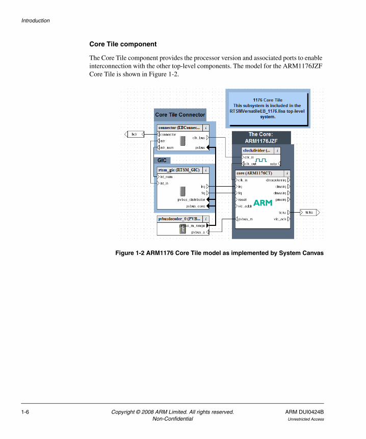
Core Tile component
The Core Tile component provides the processor version and associated ports to enable interconnection with the other top-level components. The model for the ARM1176JZF Core Tile is shown in Figure 1-2.
Figure 1-2 ARM1176 Core Tile model as implemented by System Canvas
1-6 Copyright © 2008 ARM Limited. All rights reserved. ARM DUI0424BNon-Confidential Unrestricted Access

Introduction
Emulation Baseboard component
A view of the EB Baseboard model in System Canvas is shown in Figure 1-3. The figure shows the components in block form and the ports and the interconnections between them.
Figure 1-3 EB Baseboard model as implemented by System Canvas
ARM DUI0424B Copyright © 2008 ARM Limited. All rights reserved. 1-7Unrestricted Access Non-Confidential

Introduction
1-8 Copyright © 2008 ARM Limited. All rights reserved. ARM DUI0424BNon-Confidential Unrestricted Access

Chapter 2 Getting Started
This chapter describes the procedures for building, starting and configuring a RealView® Emulation Baseboard Real-Time System Model, then running a software application on the model. The procedures differ depending on what ARM® software tools you are using, so make sure that you read the sections that apply to you. This chapter contains the following sections:
• Getting started with System Canvas for Fast Models on page 2-2
• Getting started with ARM Profiler on page 2-7
• Getting started with RealView Debugger on page 2-8
• Configuring the EB Real-Time System Model on page 2-11
• Loading and running an application on page 2-14
• Using the CLCD window on page 2-19.
ARM DUI0424B Copyright © 2008 ARM Limited. All rights reserved. 2-1Unrestricted Access Non-Confidential

Getting Started
2.1 Getting started with System Canvas for Fast Models
This section describes how to build, start and configure an EB RTSM using the Fast Models tools: System Canvas, Model Debugger and Model Shell. An example of loading and executing an application is documented separately. See Loading and running an application on page 2-14.
Note This section assumes that you are using version 4.0 or later of System Canvas, Model Debugger and Model Shell. Using other versions might not be successful. File names, interfaces and procedures could be different from those documented in this section. Model projects supplied with one version of the are not necessarily compatible with a different version. Refer to your Fast Models documentation for more information.
2.1.1 The EB Real-Time System Model build directories
The programmer’s view library is provided as part of the Fast Models tools. You must have Fast Models and the model libraries installed before you can build the models yourself. Refer to the relevant tools documentation for further information on how to install Fast Models and the model library.
If Fast Models is installed, the model build directories are in the %PVLIB_HOME%\examples\RTSMEmulationBaseboard directory.
2.1.2 Building an EB Real-Time System Model
This section uses the EB1176 Real-Time System Model as an example. If you are building a different model, substitute your model name.
1. Start System Canvas for Fast Models.
2. Click the Open button on the System Canvas toolbar.
3. Navigate to the location of the EB1176 Real-Time System Model project. This can be found at %PVLIB_HOME%\examples\RTSMEmulationBaseboard\Build_EB1176\RTSM_EB1176.sgproj. Click Open to load the project.
4. By default, you generate a debug build of the model. If you want to change this to a release build, select the Select Active Project Configuration drop-down list on the System Canvas toolbar and change the configuration to the required value.
5. Click the Build button on the System Canvas toolbar to build the model.
2-2 Copyright © 2008 ARM Limited. All rights reserved. ARM DUI0424BNon-Confidential Unrestricted Access
Getting Started
Note • Depending on your preference setting, a system check might be performed
and a window might open if warnings or errors occur. Click Proceed to start the build.
• Depending on the speed and processor loading of your computer, and particularly with release builds, your build can take several minutes to finish. Error messages are generated if there is a problem.
6. If you have used the default project settings, the build generates a Windows-Debug-compiler\cadi_system_Windows-Debug-compiler.dll or Linux-Debug-compiler/cadi_system_Linux-Debug-compiler.so object, depending on your build platform. compiler is the name of the compiler used. If you have created a Release object, substitute Release for Debug in the directory and file names. The object can be used with Model Shell or Model Debugger. See Starting the EB Real-Time System Model with the Fast Models tools. You can also use the object with ARM Profiler or RealView Debugger. See Getting started with ARM Profiler on page 2-7. See also Getting started with RealView Debugger on page 2-8.
Note On Windows, if the model you have built is to be used by others, you must ensure that you ship any necessary additional shared libraries with your model binary, and that these shared libraries are added to the end user PATH environment variable. You must include the following DLLs:
• SDL.dll
• armctmodel.dll
• pktethernet.dll.
You must also ensure that the end user has a compatible version of Microsoft Visual Studio installed for running debug builds, or the Microsoft Visual Studio Redistributable Package for release builds.
2.1.3 Starting the EB Real-Time System Model with the Fast Models tools
After you have built an EB RTSM, you have a choice of how to run the model. See the following sections for more information on using the tools:
• Using Model Shell on page 2-4
• Using Model Debugger on page 2-5
ARM DUI0424B Copyright © 2008 ARM Limited. All rights reserved. 2-3Unrestricted Access Non-Confidential
Getting Started
Using Model Shell
The EB RTSM can be started with its own CADI debug server. This allows the model to be run independently of a debugger such as RealView Debugger or Model Debugger. However, it does mean that you must configure your model using arguments that are passed to the model at start time.
To start the EB RTSM using Model Shell, change to the directory where your model file is and at the command prompt type:
model_shell --cadi-server --model model_name [--config-file filename] [-C
instance.parameter=value] [--application app_filename]
where:
model_name is the name of the model file. By default this file name is usually cadi_system_Windows-Debug-compiler.dll on Windows or cadi_system_Linux-Debug-compiler.so on Linux. compiler is the name of the compiler used to build the model.
filename is the name of your optional plain-text configuration file. Configuration files make it easier for you to manage multiple parameters at once. See Using a configuration file on page 2-11.
instance.parameter=value
is the optional direct setting of a configuration parameter. See Using the command line on page 2-11.
app_filename is the file name of an optional image to load to your model at startup.
Note On Windows, you might need to add the directory in which the Model Shell executable is found to your PATH. This location is typically:
C:\Program Files\ARM\ModelDebugger_4.0\bin
Further information on all Model Shell options and how it works is provided in other documentation. See the RealView Model Debugger User Guide.
Starting the model opens the Real-Time System Model CLCD display. See Using the CLCD window on page 2-19. Once the EB RTSM has been started, you can connect to it using a CADI-compliant debugger such as Model Debugger or RealView Debugger.
2-4 Copyright © 2008 ARM Limited. All rights reserved. ARM DUI0424BNon-Confidential Unrestricted Access

Getting Started
Using Model Debugger
You can start the EB RTSM using Model Debugger directly from System Canvas. With your model project loaded and built, click the Debug button in the System Canvas toolbar. This starts Model Debugger with the EB RTSM preloaded. Before the model starts you can define its instantiation parameters in the Configure Model Parameters dialog. See Using a configuration GUI in Model Debugger on page 2-12.
Alternatively you can start Model Debugger separately and load the model library yourself, but if using Windows you must first ensure that you have all required DLLs on your PATH. See the Note at the end of Building an EB Real-Time System Model on page 2-2. Further details on how to use Model Debugger, including configuration, are covered elsewhere. See the RealView Model Debugger User Guide.
Before the model starts, you are able to configure certain instantiation-time parameters using the Configure Model Parameters dialog. Valid settings for the EB RTSM parameters and their effects are listed later in this document. See Model configuration parameters on page 3-6.
Connecting to a running Model Shell using Model Debugger
1. In Model Debugger, select File → Connect to Model. This displays the Connect Remote dialog, shown in Figure 2-1.
Figure 2-1 Model Debugger Connect remote dialog
2. In the Connect Remote dialog, select the entry for the EB RTSM. Click Connect. This opens the Select Target dialog, shown in Figure 2-2 on page 2-6.
ARM DUI0424B Copyright © 2008 ARM Limited. All rights reserved. 2-5Unrestricted Access Non-Confidential

Getting Started
Figure 2-2 Model Debugger Select Targets dialog
3. Choose which targets you want to load. By default, the processor corresponding to the ARM processor in your EB RTSM is selected, and must be loaded. Click OK.
4. Model Debugger prompts you to load an application (image) to the model. Select the application image from the Load Application dialog and click Open.
You can now control and debug the model using Model Debugger. You can make multiple debugger connections to a single model instance.
When you want to shut down the model, return to the command window that you used to start the model and press Ctrl + C to stop the CADI server. The Model Shell process must be in the foreground before you can shut it down.
2-6 Copyright © 2008 ARM Limited. All rights reserved. ARM DUI0424BNon-Confidential Unrestricted Access

Getting Started
2.2 Getting started with ARM Profiler
ARM Profiler v2.0 allows you to connect to one of the EB RTSMs supplied with RealView Development Suite v4.0, or to an RTSM including profiling support that you have built yourself in System Canvas v4.0 SP1 or later. Your own model must include the profiler-enable parameter. See Building an EB Real-Time System Model on page 2-2.
Note The RTSMs supplied with System Canvas v4.0 and v4.0 SP1 are not compatible with RealView Profiler v1.x.
To collect profiling data from within ARM Profiler, you must define a run configuration in the ARM Workbench. This lets you specify the RTSM to use, define the names of the executable image and analysis file, and pass commands to define instantiation time parameters to the model. The syntax for instantiation time commands is defined later. See Model configuration parameters on page 3-6.
When you start the ARM Profiler data collection run, an instance of Model Shell and the CLCD are started. See Using the CLCD window on page 2-19. The CLCD is automatically closed when the simulation terminates, but you can interact with it while it is visible. Semihosting input and output can be redirected to the ARM Profiler console through the run configuration options. Once your profiling run is complete, an analysis file is generated and the results shown in ARM Profiler.
Alternatively, you can generate your analysis file by setting profiling parameters at model instantiation time in Model Debugger, then load the analysis file into ARM Profiler afterwards. See Profiling parameters on page 3-13.
Note You cannot generate an ARM Profiler analysis file with an RTSM through RealView Debugger.
Full instructions on how to collect profiling data directly in ARM Profiler using a Real-Time System Model are given in separate documentation. See the ARM Profiler User Guide.
ARM DUI0424B Copyright © 2008 ARM Limited. All rights reserved. 2-7Unrestricted Access Non-Confidential
Getting Started
2.3 Getting started with RealView Debugger
This section describes how to connect to an EB Real-Time System Model using RealView Debugger. It assumes that you are using the EB RTSMs provided with RealView Development Suite Professional v4.0.
An example of loading and executing an application is documented separately. See Loading and running an application on page 2-14.
Detailed information on how to use RealView Debugger is covered elsewhere. See the RealView Debugger User Guide.
Note The EB RTSMs supplied with System Canvas (version 4.0 or later) only work with RealView Debugger (version 3.1 or later).
The instructions in this section apply to RealView Debugger v3.1 or later. Attempting to use other versions of RealView Debugger might not be successful, as details of connection methods can change between releases.
You cannot generate an ARM Profiler analysis file for an RTSM through RealView Debugger, even if you configure the model to enable profiling.
You are supplied with pre-built EB Real-Time System Models for the Cortex-A9 MP single core, Cortex-A8, Cortex-R4, ARM1176JZF, ARM1136JF, and ARM926EJ processors.
2.3.1 Connecting to the EB Real-Time System Model in RealView Debugger
There are two different ways in which you can connect to an EB RTSM:
• Starting the EB Real-Time System Model as an RTSM connection on page 2-9
• Connecting to a running model using RealView Debugger on page 2-10.
Note You must not connect to more than one RTSM at any one time in RealView Debugger. If you do, you might experience unexpected behavior, including crashes.
2-8 Copyright © 2008 ARM Limited. All rights reserved. ARM DUI0424BNon-Confidential Unrestricted Access
Getting Started
Starting the EB Real-Time System Model as an RTSM connection
You can add the EB RTSM to the RealView Debugger Connect to Target window under the Real-Time System Model (RTSM) debug interface configuration.
1. In RealView Debugger, select Target → Connect to Target... to open the Connect to Target window.
2. Click the Add button beside the Real-Time System Model (RTSM) debug interface name. This opens the Model Configuration Utility window:
• The RTSM models are automatically displayed in the list based on the path set b the ARM_RTSM_PATH variable.
• If the ARM_RTSM_PATH variable has not been set, click the Browse... button to open a file browser for locating the EB RTSM. You can find these models in: %ARMROOT%\SysGen\PVExamples\4.0\nn\external\lib\environment\Release where
nn is a number
environment is the name of the platform and compiler.
The model file names are of the form RTSMEmulationBaseboard_CTprocessor.dll on Windows, or RTSMEmulationBaseboard_CTprocessor.so on Linux, where
processor is one of the supplied processor models, such as 1176.
• If you have separately installed and built an EB RTSM yourself using System Canvas, you can load the models from your %PVLIB_HOME%\examples\RTSMEmulationBaseboard\Build_EBprocessor\platform-build-compiler directory, where
processor is one of the supplied processor models. such as ARM1176.
platform-build-compiler is the platform, build type, and compiler, for example Linux-Release-GCC-3.4.
See Building an EB Real-Time System Model on page 2-2.
3. Select the model you want to use in the Models pane on the left side of the Model Configuration Utility. Configure the device parameters if required. See Using a configuration GUI in RealView Debugger on page 2-12. When you have finished, or if you do not want to configure any parameters, click OK.
ARM DUI0424B Copyright © 2008 ARM Limited. All rights reserved. 2-9Unrestricted Access Non-Confidential

Getting Started
4. In the RealView Debugger Connect to Target window, double click on your newly-created target to connect to it. If you are grouping targets by Configuration, expand the target connection tree view to see your target instance. Connecting to a target opens a CLCD window.
Connecting to a running model using RealView Debugger
You can use RealView Debugger to connect to an already running Model Shell instance of the EB RTSM. You can make multiple debugger connections to a single model instance.
1. Start Model Shell, if it is not already running. See Using Model Shell on page 2-4.
2. In RealView Debugger, select Target → Connect to Target... to open the Connect to Target window.
3. Click the Add button beside the SoC Designer debug interface name. The debugger detects any running CADI servers and displays them in a pop-up window. The core tile in your running EB RTSM is automatically selected. Click OK.
4. In the RealView Debugger Connect to Target window, double click on your newly-created SoC Designer target to connect to it.
Semihosting support
The simulator handles semihosting by intercepting SVC 0x123456 or 0xAB, depending on whether the processor is in ARM or Thumb state. All other SVCs are handled by causing the simulated core to jump to the SVC vector.
It is not necessary to disable semihosting support in order to boot an operating system, as long as the operating system does not use SVC0x123456 or 0xAB for its own purposes.
Semihosting support can be disabled by modifying the value of the @Semihosting_State register in RealView Debugger by either:
• using the Semihost tab of the Register pane
• at the command-line entering:
RVD> setreg @Semihosting_State=0
2-10 Copyright © 2008 ARM Limited. All rights reserved. ARM DUI0424BNon-Confidential Unrestricted Access
Getting Started
2.4 Configuring the EB Real-Time System Model
This section describes how to configure Emulation Baseboard Real-Time System Models.
2.4.1 Setting model configuration options
The initial state of the EB RTSM can be controlled by configuration settings provided either on the command line or in the CADI properties for the model. If you are starting the model using a graphical tool such as Model Debugger or RealView Debugger, you can define the instantiation-time parameters through a GUI.
Valid user settings for the EB RTSM parameters and their effects are described elsewhere. See Model configuration parameters on page 3-6.
Using a configuration file
You can configure a model that you start from the command line with Model Shell by including a reference to an optional plain text configuration file. See Using Model Shell on page 2-4. Each line of the configuration file contains the name of the component instance, the parameter to be modified and its value. Comment lines begin with a # character. Boolean values can be set using either true/false or 1/0. Strings must be enclosed in double quotes if they contain whitespace. For example:
# Disable semihosting using true/false syntaxcoretile.core.semihosting-enable=false## Enable the boot switch using 1/0 syntaxbaseboard.sp810_sysctrl.use_s8=1## Set the boot switch positionbaseboard.eb_sysregs_0.boot_switch_value=1## Enable ARM Profiler data collection and set analysis file namecoretile.core.profiler-enable=truecoretile.core.profiler-output_file=”test run output.apa”
Using the command line
You can define model parameters when you invoke the model by using the -C switch when starting Model Shell. You can also use --parameter as a synonym for the -C switch. See Using Model Shell on page 2-4. Use the same syntax as for a configuration file, but each parameter must be preceded by the -C switch.
ARM DUI0424B Copyright © 2008 ARM Limited. All rights reserved. 2-11Unrestricted Access Non-Confidential
Getting Started
Using a configuration GUI in Model Debugger
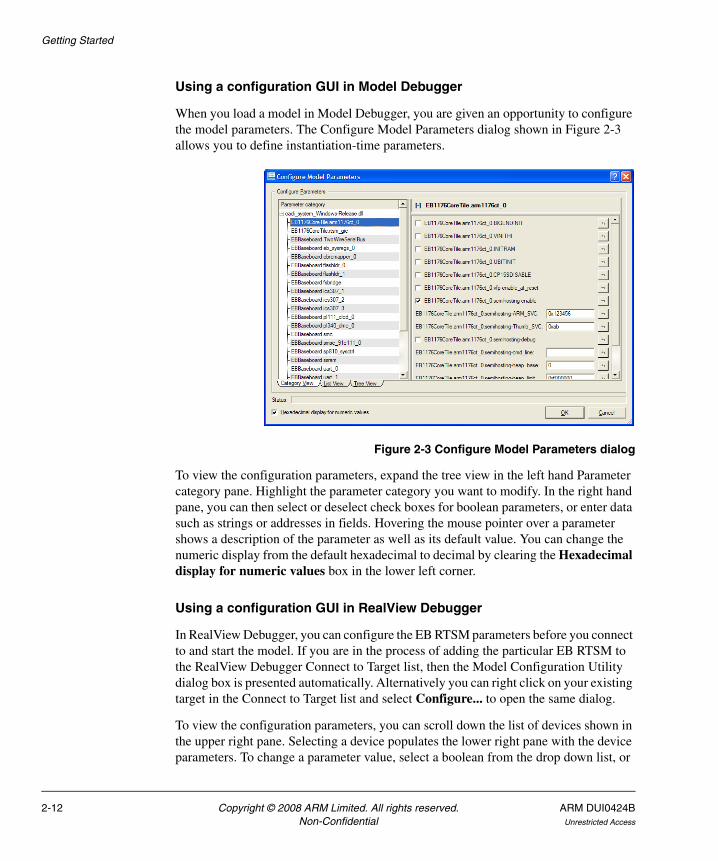
When you load a model in Model Debugger, you are given an opportunity to configure the model parameters. The Configure Model Parameters dialog shown in Figure 2-3 allows you to define instantiation-time parameters.
Figure 2-3 Configure Model Parameters dialog
To view the configuration parameters, expand the tree view in the left hand Parameter category pane. Highlight the parameter category you want to modify. In the right hand pane, you can then select or deselect check boxes for boolean parameters, or enter data such as strings or addresses in fields. Hovering the mouse pointer over a parameter shows a description of the parameter as well as its default value. You can change the numeric display from the default hexadecimal to decimal by clearing the Hexadecimal display for numeric values box in the lower left corner.
Using a configuration GUI in RealView Debugger
In RealView Debugger, you can configure the EB RTSM parameters before you connect to and start the model. If you are in the process of adding the particular EB RTSM to the RealView Debugger Connect to Target list, then the Model Configuration Utility dialog box is presented automatically. Alternatively you can right click on your existing target in the Connect to Target list and select Configure... to open the same dialog.
To view the configuration parameters, you can scroll down the list of devices shown in the upper right pane. Selecting a device populates the lower right pane with the device parameters. To change a parameter value, select a boolean from the drop down list, or
2-12 Copyright © 2008 ARM Limited. All rights reserved. ARM DUI0424BNon-Confidential Unrestricted Access
Getting Started
enter data such as strings or addresses by clicking in the relevant field. Hovering the mouse pointer over a device or parameter will show a description or additional information. You can change the numeric display from decimal to hexadecimal by right clicking on the parameter value in the lower right pane and selecting Hexadecimal Display from the resulting context menu.
ARM DUI0424B Copyright © 2008 ARM Limited. All rights reserved. 2-13Unrestricted Access Non-Confidential
Getting Started
2.5 Loading and running an application
Example applications are provided for use with the Real-Time System Models for the Evaluation Baseboard.
Note These applications are provided for demonstration purposes only and are not supported by ARM. The number of examples or implementation details might change with different versions of the system model.
A useful example application that runs on all versions of the EB RTSM is:
brot.axf This demo application provides a simple demonstration of rendering an image to the CLCD display. Source code is supplied.
If you are using the Fast Model Portfolio, then you can find examples in the %PVLIB_HOME%\images directory.
In RVDS, the source code is available in the directory %ARMROOT%\Examples\4.0\nn\platform\mandelbrot, where nn is a number.
2.5.1 Running the brot application in Model Debugger
This section describes the steps to load and run the brot.axf image in Model Debugger.
1. Start Model Debugger and connect to the system model. See Starting the EB Real-Time System Model with the Fast Models tools on page 2-3.
2. Click the Open button on the main toolbar to open the Load Application dialog that lets you select the application file to load.
3. Browse to the location of the brot.axf image. Click Open to load the image to the target.
4. Click the Open toolbar button again and browse to the location of the brot.c source file. Click Open to load the source into the Model Debugger source pane.
5. Click in the source pane and place a breakpoint on the render function. This appears on line 154 of the source code.
6. Press F5, or select Run from the Debug menu, until the CLCD window displays an image similar to that shown in Figure 2-4 on page 2-15.
2-14 Copyright © 2008 ARM Limited. All rights reserved. ARM DUI0424BNon-Confidential Unrestricted Access

Getting Started
Figure 2-4 CLCD window
7. Repeatedly press F5 and notice how the CLCD window changes.
2.5.2 Running the brot application in ARM Profiler
This section briefly describes the steps to load and run the brot.axf image through ARM Profiler, including displaying the profiling results. More detailed information on run configuration options is available separately. See the ARM Profiler User Guide.
Note RTSMs build with System Canvas v4.0, and RTSMs supplied with RVDS v4.0, cannot be profiled with RealView Profiler v1.x.
1. Start ARM Workbench IDE.
2. From the main menu, select Run → Open Run Dialog.... This opens the Run dialog, shown in Figure 2-5 on page 2-16.
ARM DUI0424B Copyright © 2008 ARM Limited. All rights reserved. 2-15Unrestricted Access Non-Confidential

Getting Started
Figure 2-5 ARM Profiler Run dialog
3. Select the model to run in the Model drop down list. You can choose one of the RTSMs supplied with ARM Profiler, or if you have built your own, use the Custom option.
4. Browse to the location of the brot.axf image in the Image field.
5. Set the execution time limit to 60 seconds by entering 60 in the Time Limit text field.
6. Click Run to start the model running.
7. When execution stops, an analysis similar to that in Figure 2-6 on page 2-17 is shown.
2-16 Copyright © 2008 ARM Limited. All rights reserved. ARM DUI0424BNon-Confidential Unrestricted Access

Getting Started
Figure 2-6 ARM Profiler analysis
2.5.3 Running the brot application in RealView Debugger
This section describes the steps to load and run the brot.axf image in RealView Debugger:
Note You might need to build the brot.axf image first. Instructions and build scripts are provided in %ARMROOT%\Examples\4.0\nn\platform\mandelbrot, where nn is a number.
1. Start RealView Debugger and connect to the system model. See Connecting to the EB Real-Time System Model in RealView Debugger on page 2-8.
ARM DUI0424B Copyright © 2008 ARM Limited. All rights reserved. 2-17Unrestricted Access Non-Confidential

Getting Started
2. Select Load Image from the Target menu. The Select Local Files to Load dialog is displayed.
3. Browse to the location of brot.axf, select it, then click Open.
4. Select the brot.c tab in the RealView Debugger main window and place a breakpoint on the render function, as shown in Figure 2-7.
Figure 2-7 Breakpoint in brot.c
5. Press F5, or select Run from the Debug menu, until the CLCD window is displayed as shown in Figure 2-4 on page 2-15.
6. Repeatedly press F5 and notice how the CLCD window changes.
2-18 Copyright © 2008 ARM Limited. All rights reserved. ARM DUI0424BNon-Confidential Unrestricted Access

Getting Started
2.6 Using the CLCD window
When the RTSM starts, a window with the following title is opened:
Real-Time System Model CLCD
This window is used to represent the contents of the simulated color LCD framebuffer. It automatically resizes to match the horizontal and vertical resolution that is set up in the CLCD peripheral registers. Further information on the CLCD model components and other peripherals is in separate documentation. See the Fast Model Portfolio Peripheral Components Reference Manual. See also the Fast Model Portfolio Emulation Baseboard Components Reference Manual.
Figure 2-8 shows the EB RTSM CLCD in its default state, immediately after being started.
Figure 2-8 CLCD window at startup
The top section of the CLCD window displays the following status information:
USERSW Eight white boxes showing the state of the EB User DIP switches. These represent switch S6 on the EB hardware, USERSW[8:1], which is mapped to bits [7:0] of the SYS_SW register at address 0x10000004. The switches are in the off position by default. Click in the area above or below a white box to change its state. See Switch S6 on page 3-7.
BOOTSW Eight white boxes showing the state of the EB Boot DIP switches. These represent switch S8 on the EB hardware, BOOTSEL[8:1], which is mapped to bits [15:8] of the SYS_SW register at address 0x100000004. The switches are in the off position by default. See Switch S8 on page 3-9.
Note You are recommended to configure the Boot DIP switches by using the
boot_switch model parameter rather than by using the CLCD interface. Changing Boot DIP switch positions while the model is running can result in unpredictable behavior.
ARM DUI0424B Copyright © 2008 ARM Limited. All rights reserved. 2-19Unrestricted Access Non-Confidential
Getting Started
S6LED Eight colored boxes, indicating the state of the EB User LEDs. These represent LEDs D[21:14] on the EB hardware, which are mapped to bits [7:0] of the SYS_LED register at address 0x10000008. The boxes correspond to the red/yellow/green LEDs on the EB hardware.
Total Instr A counter showing the total number of instructions executed so far. Because the system model models are provide a programmer’s view of the system, the CLCD displays total instructions rather than total core cycles. Timing might differ substantially from the hardware because:
• the bus fabric is simplified
• memory latencies are minimized
• cycle approximate core and peripheral models are used.
In general bus transaction timing is consistent with the hardware, but timing of operations within the model is not accurate.
Total Time A counter showing the total elapsed time, in seconds. This is wall clock time, not simulated time.
Rate Limit A feature that disables or enables fast simulation. Because the system model is highly optimized, your code might run faster than it would on real hardware. This could cause timing issues. If Rate Limit is enabled, which it is by default, simulation time is restricted so that it more closely matches real time. See Timing considerations on page 3-32.
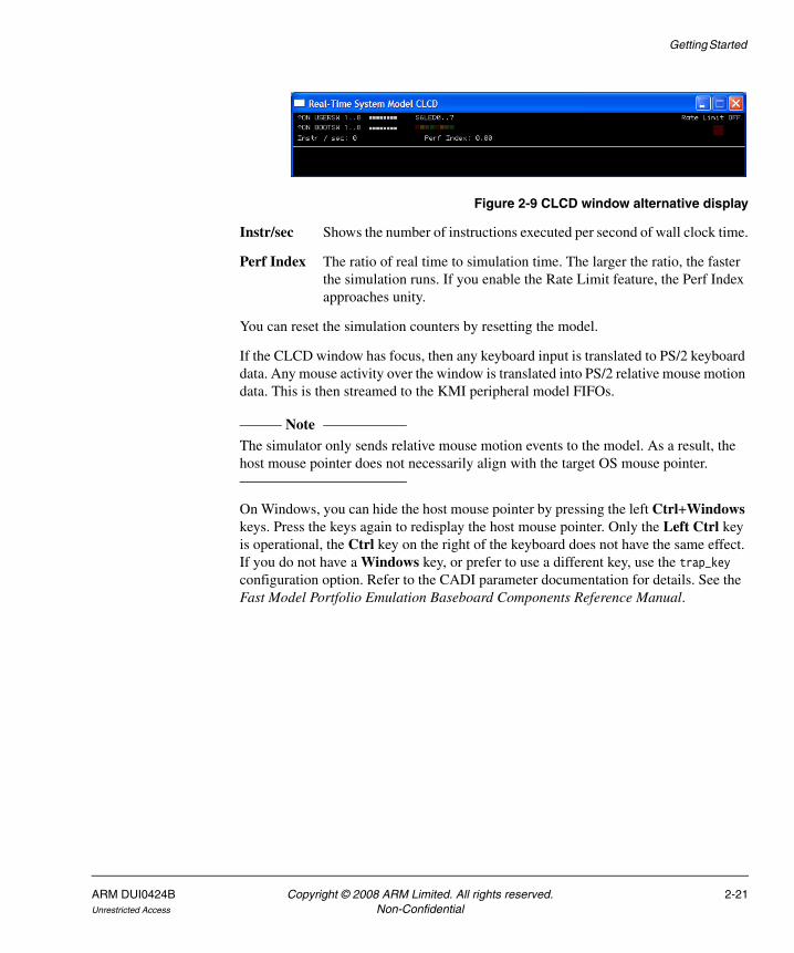
Click on the square button to disable or enable Rate Limit. The text changes from ON to OFF, and the colored box becomes darker when Rate Limit is disabled. Figure 2-9 on page 2-21 shows the CLCD with Rate Limit disabled.
Note You can control whether Rate Limit is enabled by using the
rate_limit-enable parameter when instantiating the model. See Visualisation parameters on page 3-12.
If you click on the Total Instr or Total Time items in the CLCD, the display changes to show two different items, as shown in Figure 2-9 on page 2-21. You can click on the items again to toggle between the original and alternative displays.
2-20 Copyright © 2008 ARM Limited. All rights reserved. ARM DUI0424BNon-Confidential Unrestricted Access
Getting Started
Figure 2-9 CLCD window alternative display
Instr/sec Shows the number of instructions executed per second of wall clock time.
Perf Index The ratio of real time to simulation time. The larger the ratio, the faster the simulation runs. If you enable the Rate Limit feature, the Perf Index approaches unity.
You can reset the simulation counters by resetting the model.
If the CLCD window has focus, then any keyboard input is translated to PS/2 keyboard data. Any mouse activity over the window is translated into PS/2 relative mouse motion data. This is then streamed to the KMI peripheral model FIFOs.
Note The simulator only sends relative mouse motion events to the model. As a result, the host mouse pointer does not necessarily align with the target OS mouse pointer.
On Windows, you can hide the host mouse pointer by pressing the left Ctrl+Windows keys. Press the keys again to redisplay the host mouse pointer. Only the Left Ctrl key is operational, the Ctrl key on the right of the keyboard does not have the same effect. If you do not have a Windows key, or prefer to use a different key, use the trap_key configuration option. Refer to the CADI parameter documentation for details. See the Fast Model Portfolio Emulation Baseboard Components Reference Manual.
ARM DUI0424B Copyright © 2008 ARM Limited. All rights reserved. 2-21Unrestricted Access Non-Confidential

Getting Started
2-22 Copyright © 2008 ARM Limited. All rights reserved. ARM DUI0424BNon-Confidential Unrestricted Access
Chapter 3 Programmer’s Reference
This chapter describes the memory map and the configuration registers for the peripheral and system component models. It contains the following sections:
• Memory map on page 3-2
• Model configuration parameters on page 3-6
• Differences between the EB hardware and the system model on page 3-27.
Note For detailed information on the programming interface for ARM® PrimeCell® peripherals and controllers, see the appropriate technical reference manual.
ARM DUI0424B Copyright © 2008 ARM Limited. All rights reserved. 3-1Unrestricted Access Non-Confidential

Programmer’s Reference
3.1 Memory map
The locations and interrupts for memory, peripherals, and controllers used in the EB Real-Time System Models are listed in Table 3-1. See the Emulation Baseboard User Guide for more detail on the controllers and peripherals.
Table 3-1 Memory map and interrupts for standard peripherals
Peripheral Modeled Address range Bus SizeGIC Inta
DCCIIntb
Dynamic memory Yes 0x00000000–0x0FFFFFFF AHB 256MB - -
System registers (see Status and system control registers on page 3-32)
Yes 0x10000000–0x10000FFF APB 4KB - -
SP810 System Controller Yes 0x10001000–0x10001FFF APB 4KB - -
Two-Wire Serial Bus Interface No 0x10002000–0x10002FFF APB 4KB - -
Reserved - 0x10003000–0x10003FFF APB 4KB - -
PL041 Advanced Audio CODEC Interface (AACI)
Partialc 0x10004000–0x10004FFF APB 4KB 51 51
PL180 MultiMedia Card Interface (MCI)
Partiald 0x10005000–0x10005FFF APB 4KB 49, 50 49, 50
Keyboard/Mouse Interface 0 Yes 0x10006000–0x10006FFF APB 4KB 52 7
Keyboard/Mouse Interface 1 Yes 0x10007000–0x10007FFF APB 4KB 53 8
Character LCD Interface No 0x10008000–0x10008FFF APB 4KB 55 55
UART 0 Interface Yes 0x10009000–0x10009FFF APB 4KB 44 4
UART 1 Interface Yes 0x1000A000–0x1000AFFF APB 4KB 45 5
UART 2 Interface Yes 0x1000B000–0x1000BFFF APB 4KB 46 46
UART 3 Interface Yes 0x1000C000–0x1000CFFF APB 4KB 47 47
Synchronous Serial Port Interface Yes 0x1000D000–0x1000DFFF APB 4KB 43 43
Smart Card Interface No 0x1000E000–0x1000EFFF APB 4KB 62 62
Reserved - 0x1000F000–0x1000FFFF APB 4KB - -
SP805 Watchdog Interface Yes 0x10010000–0x10010FFF APB 4KB 32 32
3-2 Copyright © 2008 ARM Limited. All rights reserved. ARM DUI0424BNon-Confidential Unrestricted Access

Programmer’s Reference
SP804 Timer modules 0 and 1 interface
(Timer 1 starts at 0x10011020)
Yes 0x10011000–0x10011FFF APB 4KB 36 1
SP804 Timer modules 2 and 3 interface
(Timer 3 starts at 0x10020020)
Yes 0x10012000–0x10012FFF APB 4KB 37 2
PL061 GPIO Interface 0 Yes 0x10013000–0x10013FFF APB 4KB 38 38
PL061 GPIO Interface 1 Yes 0x10014000–0x10014FFF APB 4KB 39 39
PL061 GPIO Interface 2 (miscellaneous onboard I/O)
Yes 0x10015000–0x10015FFF APB 4KB 40 40
Reserved - 0x10016000–0x10016FFF APB 4KB - -
PL030 Real Time Clock Interface Yes 0x10017000–0x10017FFF APB 4KB - -
Dynamic Memory Controller configuration
Partiale 0x10018000–0x10018FFF APB 4KB - -
PCI controller configuration registers No 0x10019000–0x10019FFF AHB 4KB - -
Reserved - 0x1001A000–0x1001FFFF APB 24KB - -
PL111 Color LCD Controller Yes 0x10020000–0x1002FFFF AHB 64KB 55 55
DMA Controller configuration registers Yes 0x10030000–0x1003FFFF AHB 64KB - -
Generic Interrupt Controller 1 Yesf 0x10040000–0x1004FFFF AHB 64KB - -
Generic Interrupt Controller 2 (nFIQ for tile 1)
Nog 0x10050000–0x1005FFFF AHB 64KB - -
Generic Interrupt Controller 3 (nIRQ for tile 2)
Nog 0x10060000–0x1006FFFF AHB 64KB - -
Generic Interrupt Controller 4 (nFIQ for tile 2)
Nog 0x10070000–0x1007FFFF AHB 64KB - -
PL350 Static Memory Controller configurationh
Yes 0x10080000–0x1008FFFF AHB 64KB - -
Reserved - 0x10090000–0x100EFFFF AHB 448MB - -
Table 3-1 Memory map and interrupts for standard peripherals (continued)
Peripheral Modeled Address range Bus SizeGIC Inta
DCCIIntb
ARM DUI0424B Copyright © 2008 ARM Limited. All rights reserved. 3-3Unrestricted Access Non-Confidential

Programmer’s Reference
Debug Access Port (DAP) ROM table. Some debuggers read information on the target processor and the debug chain from the DAP table.
No 0x100F0000–0x100FFFFF AHB 64KB - -
Reserved - 0x10100000–0x1FFFFFFF - 255MB - -
Reserved - 0x20000000–0x3FFFFFFF - 512MB - -
NOR Flash Yesi 0x40000000–0x43FFFFFF AXI 64MB - -
Disk on Chip No 0x44000000–0x47FFFFFF AXI 64MB 41 41
SRAM Yes 0x48000000–0x4BFFFFFF AXI 64MB - -
Configuration flash No 0x4C000000–0x4DFFFFFF AXI 32MB - -
Ethernet Yesj 0x4E000000–0x4EFFFFFF AXI 16MB 60 60
USB No 0x4F000000–0x4FFFFFFF AXI 16MB - -
PISMO expansion memory No 0x50000000–0x5FFFFFFF AXI 256MB 58 58
PCI interface bus windows No 0x60000000–0x6FFFFFFF AXI 256MB - -
Dynamic memory (mirror) Yes 0x70000000–0x7FFFFFFF AXI 256MB - -
a. The Interrupt signal column lists the value to use when programming your interrupt controller. The values shown are after mapping the SPI number by adding 32. The interrupt numbers from the peripherals are modified by adding 32 to form the interrupt number seen by the GIC. GIC interrupts 0-31 are for internal use.
b. For the EB model that uses the Cortex-A9, a DIC is used as the interrupt controller instead of the GIC. The numbers in this column are the interrupt numbers used by the DCCI system.
c. See Sound on page 3-28.d. The implementation of the PL180 is currently limited, so not all features are present.e. See Differences between the EB hardware and the system model on page 3-27.f. The Cortex™-A9 models implement an internal GIC. This is mapped at 0x1F000000 - 0x1F001FFF.g. The EB RTSM GICs are not the same as those implemented on the EB hardware as the register map is different. See Generic
Interrupt Controller on page 3-32.h. Although the EB hardware uses the PL093 static memory controller, the model implements PL350. These are functionally
equivalent.i. This peripheral is implemented in the IntelStrataFlashJ3 component in the EB RTSM.j. This peripheral is implemented in the SC91C111 component in the EB RTSM.
Table 3-1 Memory map and interrupts for standard peripherals (continued)
Peripheral Modeled Address range Bus SizeGIC Inta
DCCIIntb
3-4 Copyright © 2008 ARM Limited. All rights reserved. ARM DUI0424BNon-Confidential Unrestricted Access

Programmer’s Reference
Note The EB RTSMs implement memory in such a way that it works without the need to correctly program the memory controller first. This means that when you start to use hardware, you must ensure that the memory controller is set up properly, otherwise applications that run on an RTSM might fail on real hardware.
ARM DUI0424B Copyright © 2008 ARM Limited. All rights reserved. 3-5Unrestricted Access Non-Confidential

Programmer’s Reference
3.2 Model configuration parameters
The EB Real-Time System Models have parameters that can be defined at instantiation or run time. Parameters that can be modified only at model build time, or that are not normally modified by the user in the equivalent hardware system, are not discussed. Unless otherwise described in the model release notes, these additional parameters are not intended to be changed by the end user.
In a GUI debugger such as Model Debugger or RealView® Debugger, you can find the parameters listed under the component names in the configuration dialog. See Using a configuration GUI in Model Debugger on page 2-12. See also Using a configuration GUI in RealView Debugger on page 2-12. If you are using text configuration, details of the parameter syntax to use are given with the parameter lists in this section.
Further information on all parameters is available in the following documentation:
• Emulation Baseboard User Guide (Lead Free)
• Model Portfolio Peripheral Components Reference Manual
• Fast Model Portfolio Emulation Baseboard Components Reference Manual.
This section lists the following model parameter sets:
• Baseboard parameters
• Ethernet parameters on page 3-9
• UART parameters on page 3-11
• Terminal parameters on page 3-11
• Visualisation parameters on page 3-12
• Profiling parameters on page 3-13
• ARMCortexA9MPCT RTSM parameters on page 3-14
• ARMCortexA8CT RTSM parameters on page 3-18
• ARMCortexR4CT RTSM parameters on page 3-20
• ARM1176CT RTSM parameters on page 3-22
• ARM1136CT RTSM parameters on page 3-24
• ARM926CT RTSM parameters on page 3-25.
3.2.1 Baseboard parameters
Table 3-2 on page 3-7 lists the EB RTSM instantiation time parameters that you can change when you start the model. The syntax to use in a configuration file is:
3-6 Copyright © 2008 ARM Limited. All rights reserved. ARM DUI0424BNon-Confidential Unrestricted Access

Programmer’s Reference
baseboard.component_name.parameter=value
Switch S6
Switch S6 is equivalent to the Boot Monitor configuration switch on the EB hardware. Default settings are listed in Table 3-3 on page 3-8. If you have the standard ARM Boot Monitor flash image loaded, the setting of switch S6-1 changes what happens on model
Table 3-2 EBBaseboard Model instantiation parameters
Component name Parameter Description Type Values Default
eb_sysregs_0 user_switches_ value
switch S6 setting integer see Switch S6 0
eb_sysregs_0 boot_switch_ value
switch S8 setting integer see Switch S8 on page 3-9
0
flashldr_0 fname path to flash image file string valid filename
[empty string]
flashldr_1 fname path to flash image file string valid filename
[empty string]
mmc p_mmc_file multimedia card filename string valid filename
mmc.dat
pl111_clcd_0 pixel_double_ limit
sets threshold in horizontal pixels below which pixels sent to framebuffer doubled in size in both dimensions
integer - 0x12c
smc REMAP indicates which channel of the SMC is bootable
integer -1, 0-7 -1 (no remap)
sp810_sysctrl use_s8 indicates whether to read boot_switches_value
boolean true/false false
vfs2 mount mount point for the host filesystem
string see Mount names on page 4-13
[empty string]
ARM DUI0424B Copyright © 2008 ARM Limited. All rights reserved. 3-7Unrestricted Access Non-Confidential

Programmer’s Reference
reset. Otherwise, the function of switch S6 is implementation dependent. If you want to write the switch position directly to the S6 parameter in the model, you must convert the switch settings to an integer value from the equivalent binary, where 1 is on and 0 is off.
If S6-1 is in the ON position, the Boot Monitor executes the boot script that was loaded into flash. If there is no script, the Boot Monitor prompt is displayed.
The settings of S6-2 and S6-3 affect STDIO source and destination on model reset as defined in Table 3-4.
Further information on Boot Monitor configuration and commands can be found in separate documentation. See the Emulation Baseboard User Guide (Lead Free).
Table 3-3 Default positions for EB System Model switch S6
SwitchDefault Position
Function in default position
S6-1 OFF Displays prompt allowing Boot Monitor command entry after system start.
S6-2 OFF See Table 3-4.
S6-3 OFF See Table 3-4.
S6-4 to S6-8 OFF Reserved for application use.
Table 3-4 STDIO redirection
S6-2 S6-3 Output Input Description
OFF OFF UART0 UART0 STDIO autodetects whether to use semihosting I/O or a UART. If a debugger is connected, STDIO is redirected to the debugger output window, otherwise STDIO goes to UART0.
OFF ON UART0 UART0 STDIO is redirected to UART0, regardless of semihosting settings.
ON OFF CLCD Keyboard STDIO is redirected to the CLCD and keyboard, regardless of semihosting settings.
ON ON CLCD UART0 STDIO output is redirected to the LCD and input is redirected to the keyboard, regardless of semihosting settings.
3-8 Copyright © 2008 ARM Limited. All rights reserved. ARM DUI0424BNon-Confidential Unrestricted Access
Programmer’s Reference
Switch S8
Switch S8 is disabled by default. To enable it, before you start the model you must change the state of the parameter baseboard.sp810_sysctrl.use_s8 to true. See Baseboard parameters on page 3-6.
If you have a Boot Monitor flash image loaded, switch S8 allows you to remap boot memory. On reset, the EB hardware starts to execute code at 0x0, which is typically volatile DRAM. You can put the contents of non-volatile RAM at this location by setting the S8 switch in the EB RTSM CLCD as shown in Table 3-5. The settings take effect on model reset.
Note Attempting to change switch S8 settings after the model has started, for example by using the CLCD DIP switches, can lead to unpredictable behavior.
3.2.2 Ethernet parameters
Note Ethernet is not supported on the EB RTSMs supplied with ARM Profiler or RealView Development Suite.
Table 3-6 on page 3-10 lists the ethernet instantiation-time parameters that you can change when you start the model. Further information on the ethernet component itself is given in a separate document. See Fast Model Portfolio Peripheral Components Reference Manual. Detailed information on how to set up and use the ethernet component is given elsewhere in this document. See Ethernet on page 4-5. The syntax to use in a configuration file is:
Table 3-5 EB System Model switch S8 settings
Switch S8[4:1]
Memory Range
Description
0000 0x40000000 - 0x4FEFFFFF
NOR flash remapped to 0x0
0001 0x44000000 - 0x47FFFFFF
NOR flash remapped to 0x0
0010 0x48000000 - 0x4BFFFFFF
SRAM remapped to 0x0
ARM DUI0424B Copyright © 2008 ARM Limited. All rights reserved. 3-9Unrestricted Access Non-Confidential

Programmer’s Reference
baseboard.smsc_91c111_0.parameter=value
where parameter is the ethernet parameter you are defining.
interface
The interface parameter has a transport and one or more optional parameters, separated by colons. It can take the form:
disabled Implement the interface as though no cable were connected.
host:controller
controller is the first host controller that matches the text substring you specify, such as eth0.
pipe:address:port
address and port are the IP address and port on which a nicserver application is listening.
mac_address
You have two options for the mac_address parameter.
For a fixed address, set the value of the mac_address parameter to a valid IP address for your network. Fixed addresses do not change when the EB RTSM is reset.
For a random value, set the mac_address parameter to auto. The address might change each time the EB RTSM is reset. This is not recommended if your network normally allocates addresses automatically using a DHCP server, because of the risk of address duplication.
Table 3-6 Ethernet instantiation parameters
Parameter Description Type Values Default
interface sets the host interface type to use
string see interface “disabled”
mac_address the MAC address to use on the host
string see mac_address
“00:01:02:03: 04:05”
promiscuous puts host ethernet controller into promiscuous mode
boolean true/false true
3-10 Copyright © 2008 ARM Limited. All rights reserved. ARM DUI0424BNon-Confidential Unrestricted Access

Programmer’s Reference
3.2.3 UART parameters
Table 3-7 lists the PL011 UART instantiation-time parameters that you can change when you start the model. The syntax to use in a configuration file is:
baseboard.uart_x.parameter=value
where x is the UART ID 0, 1, 2 or 3 and parameter is the parameter name.
3.2.4 Terminal parameters
When the EB RTSM starts, a TCP/IP port for each enabled Terminal is opened. This is port 5000 by default, but increments by 1 until a free user port is found. Detailed information on how to use the Terminal component is provided elsewhere. See Terminal on page 4-2.
Table 3-8 on page 3-12 lists the terminal instantiation-time parameters that you can change when you start the model. The syntax to use in a configuration file is:
terminal_x.parameter=value
where x is the terminal ID 0, 1, 2 or 3.
Note The telnet Terminal does not obey control flow signals. This means that the timing characteristics of Terminal are not the same as a standard serial port.
Table 3-7 UART instantiation parameters
Component name Parameter Description Type Values Default
uart_[0-3] clock_rate clock rate for PL011 integer - 0xE10000
uart_[0-3] baud_rate baud rate integer - 0x9600
uart_[0-3] uart_enable enables UART when the system starts
boolean true/false false
ARM DUI0424B Copyright © 2008 ARM Limited. All rights reserved. 3-11Unrestricted Access Non-Confidential

Programmer’s Reference
3.2.5 Visualisation parameters
Table 3-9 on page 3-13 lists the Visualisation instantiation-time parameters that you can change when you start the model. Detailed information on the Visualisation component is given in a separate document. See Fast Model Portfolio Emulation Baseboard Components Reference Manual. The syntax to use in a configuration file is:
visualisation.parameter=value.
Note The component name spelling is British, so use “visualisation” rather than “visualization”.
Table 3-8 Terminal instantiation parameters
Component name Parameter Description Type Values Default
terminal_[0-3] mode Terminal operation mode. string telneta, rawb telnet
terminal_[0-3] start_telnet Enable terminal when the system starts.
boolean true/false true
terminal_[0-3] start_port Port used for the terminal when the system starts. If the specified port is not free, the port value is incremented by 1 until a free port is found.
integer valid port number
5000
a. In telnet mode, the Terminal component supports a subset of the telnet protocol defined in RFC 854.b. In raw mode, the Terminal component does not interpret or modify the byte stream contents.
3-12 Copyright © 2008 ARM Limited. All rights reserved. ARM DUI0424BNon-Confidential Unrestricted Access
Programmer’s Reference
3.2.6 Profiling parameters
If you have a license to use ARM Profiler, and your core tile RTSM supports profiling, you can collect and interpret profiling information when you run code. You can also specify the name of the resulting analysis file. The profiling information can be collected directly by ARM Profiler. See Getting started with ARM Profiler on page 2-7. Alternatively you can run the RTSM using a tool such as Model Debugger then load the resulting analysis file into ARM Profiler afterwards.
Note You cannot use RealView Profiler v1.x with RTSMs provided with RealView Development Suite v4.0, or System Canvas v4.0 or v4.0 SP1.
RealView Debugger does not support RTSM profiling, so you cannot generate an ARM Profiler analysis file even if you enable the profiling parameters.
Table 3-9 Visualisation instantiation parameters
Parameter Description Type Values Default
disable_visualisation disable the EBVisualisation component on model startup
boolean true/false false
rate_limit-enablea
a. You can click the Rate Limit button in the CLCD instead of setting the parameter at instantiation time. See Using the CLCD window on page 2-19.
restrict simulation speed so that simulation time more closely matches real time rather than running as fast as possible
boolean true/false true
trap_key trap key that works with left Ctrl key to toggle mouse pointer display
integer valid ATKeyCode key valueb
b. See the header file, %PVLIB_HOME%\components\KeyCode.h, for a list of ATKeyCode values. On Linux, see the file $PVLIB_HOME/components/KeyCode.h.
107c
c. This is equivalent to the left Windows key.
ARM DUI0424B Copyright © 2008 ARM Limited. All rights reserved. 3-13Unrestricted Access Non-Confidential

Programmer’s Reference
All RTSMs can be built in System Canvas v4.0 SP1 to work with ARM Profiler v2.0. The EB RTSMs supplied with RealView Development Suite v4.0 also support ARM Profiler v2.0. Table 3-10 lists the profiler instantiation-time parameters that you can change when you start the model. The syntax to use in a configuration file is:
coretile.core.parameter=value
3.2.7 ARMCortexA9MPCT RTSM parameters
Table 3-11 on page 3-15 lists the Cortex™-A9 multiprocessor core tile RTSM parameters that you can change when you start the model. All listed parameters are instantiation-time parameters. This core tile RTSM is based on r0p0 of the Cortex-A9 processor.
If you are using System Canvas, you have the option of building a processor with 1, 2 or 4 cores. If you are using the RTSM provided with RVDS, you are limited to using the single core Cortex-A9 processor variant.
The syntax to use in a configuration file is:
Table 3-10 Profiler instantiation parameters
Parameter Description Type Values Default
profiler-enable enables profiling at model instantiation
boolean true/false falsea
profiler-output_file sets the name of the ARM Profiler analysis file generated by the profiler, relative to the location of the RTSM
string - [empty string]b
a. Profiling is assumed to be enabled if you are running the RTSM through ARM Profiler.b. The default analysis file name in ARM Profiler is @[email protected], where@F is the name of the image file@N is a unique number, between 001 and 999, added to the file name.
3-14 Copyright © 2008 ARM Limited. All rights reserved. ARM DUI0424BNon-Confidential Unrestricted Access
Programmer’s Reference
coretile.core.parameter=value
The Cortex-A9MP RTSM has the PERIPHBASE parameter set to 0x1F000000, which is the base address of peripheral memory space on EB hardware.
Table 3-12 on page 3-16 provides a description of the configuration parameters for each Cortex-A9MP core. These parameters are set individually for each Cortex-A9 core you have in your system. Each core has its own timer and watchdog.
The syntax to use in a configuration file is:
coretile.core.cpun.parameter=value
Table 3-11 ARMCortexA9MPCT RTSM parameters
Parameter Description TypeAllowed Value
Default Value
CLUSTER_ID CPU cluster ID value. integer 0-15 0
CFGDISABLE Disable some accesses to DIC registers.
boolean true/false false
FILTEREN Enable filtering of accesses through pvbus_m0.
boolean true/false false
FILTERSTART Base of region filtered to pvbus_m0.
integer must be aligned on 1MB boundary
0x0
FILTEREND End of region filtered to pvbus_m0.
integer must be aligned on 1MB boundary
0x0
dcache-state_modelled Set whether D-cache has stateful implementation.
boolean true/false false
dic-spi_count Number of shared peripheral interrupts implemented.
integer 0-223, in increments of 32
64
icache-state_modelled Set whether I-cache has stateful implementation.
boolean true/false false
ARM DUI0424B Copyright © 2008 ARM Limited. All rights reserved. 3-15Unrestricted Access Non-Confidential
Programmer’s Reference
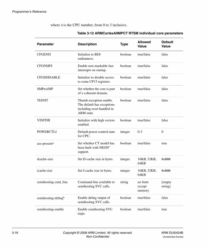
where n is the CPU number, from 0 to 3 inclusive.
Table 3-12 ARMCortexA9MPCT RTSM individual core parameters
Parameter Description TypeAllowed Value
Default Value
CFGEND Initialize to BE8 endianness.
boolean true/false false
CFGNMFI Enable non-maskable fast interrupts on startup.
boolean true/false false
CFGSDISABLE Initialize to disable access to some CP15 registers.
boolean true/false false
SMPnAMP Set whether the core is part of a coherent domain.
boolean true/false false
TEINIT Thumb exception enable. The default has exceptions including reset handled in ARM state.
boolean true/false false
VINITHI Initialize with high vectors enabled.
boolean true/false false
POWERCTLI Default power control state for CPU.
integer 0-3 0
ase-presenta Set whether CT model has been built with NEON™ support.
boolean true/false true
dcache-size Set D-cache size in bytes. integer 16KB, 32KB, 64KB
0x8000
icache-size Set I-cache size in bytes. integer 16KB, 32KB, 64KB
0x8000
semihosting-cmd_line Command line available to semihosting SVC calls.
string no limit except memory
[empty string]
semihosting-debugb Enable debug output of semihosting SVC calls.
boolean true/false false
semihosting-enable Enable semihosting SVC traps.
boolean true/false true
3-16 Copyright © 2008 ARM Limited. All rights reserved. ARM DUI0424BNon-Confidential Unrestricted Access

Programmer’s Reference
The Cortex-A9MP RTSM implementation contains a specific Distributed Interrupt Controller (DIC), rather than the Generic Interrupt Controller (GIC) used in several other EB RTSMs. The syntax to use in a configuration file is:
coretile.eb_intmapper.num_interrupts=value
semihosting-ARM_SVC ARM SVC number for semihosting.
integer 0x000000 -
0xFFFFFF
0x123456
semihosting-Thumb_SVC Thumb SVC number for semihosting.
integer 0x00 - 0xFF 0xAB
semihosting-heap_base Virtual address of heap base.
integer 0x00000000 -
0xFFFFFFFF
0x0
semihosting-heap_limit Virtual address of top of heap.
integer 0x00000000 -
0xFFFFFFFF
0x0F000000
semihosting-stack_base Virtual address of base of descending stack.
integer 0x00000000 -
0xFFFFFFFF
0x10000000
semihosting-stack_limit Virtual address of stack limit.
integer 0x00000000 -
0xFFFFFFFF
0x0F000000
vfp-enable_at_resetc Enable coprocessor access and VFP at reset.
boolean true/false false
vfp-presenta Set whether CT model has been built with VFP support.
boolean true/false true
a. The ase-present and vfp-present parameters configure the synthesis options for the Cortex-A9 model. The options are:
vfp present and ase present NEON and VFPv3-D32 supported.
vfp present and ase not present VFPv3-D16 supported.
vfp not present and ase present Illegal. Forces vfp-present to true so model has NEON and VFPv3-D32 support.
vfp not present and ase not present Model has neither NEON nor VFPv3-D32 support.
b. Currently ignored.c. This is a model specific behavior with no hardware equivalent.
Table 3-12 ARMCortexA9MPCT RTSM individual core parameters (continued)
Parameter Description TypeAllowed Value
Default Value
ARM DUI0424B Copyright © 2008 ARM Limited. All rights reserved. 3-17Unrestricted Access Non-Confidential

Programmer’s Reference
where value is the number of interrupts, from 0 to 224 inclusive. The default number is 64.
3.2.8 ARMCortexA8CT RTSM parameters
Table 3-13 lists the Cortex-A8 core tile RTSM parameters that you can change when you start the model. All listed parameters are instantiation-time parameters. This core tile RTSM is based on r2p1 of the Cortex-A8 processor.
The syntax to use in a configuration file is:
coretile.core.parameter=value
Table 3-13 ARMCortexA8CT RTSM parameters
Parameter Description Type Values Default
CFGEND0 Initialize to BE8 endianness.
boolean true/false false
CFGNMFI Enable non-maskable interrupts on startup.
boolean true/false false
CFGTE Initialize to take exceptions in Thumb state. Model starts in Thumb state.
boolean true/false false
CP15SDISABLE Initialize to disable access to some CP15 registers.
boolean true/false false
UBITINIT Initialize to ARMv6 unaligned behavior.
boolean true/false false
VINITHI Initialize with high vectors enabled.
boolean true/false false
l1_dcache-state_modelleda Include level 1 data cache state model.
boolean true/false false
l1_icache-state_modelleda Include level 1 instruction cache state model.
boolean true/false false
l2_cache-state_modelleda Include unified level 2 cache state model.
boolean true/false false
implements_vfp Set whether CT model has been built with VFP support.
boolean true/false true
3-18 Copyright © 2008 ARM Limited. All rights reserved. ARM DUI0424BNon-Confidential Unrestricted Access

Programmer’s Reference
The Cortex-A8 core tile RTSM also includes a GIC but this cannot be configured at instantiation time.
semihosting-cmd_line Command line available to semihosting SVC calls.
string no limit except memory
[empty string]
semihosting-debugb Enable debug output of semihosting SVC calls.
boolean true/false false
semihosting-enable Enable semihosting SVC traps.
boolean true/false true
semihosting-ARM_SVC ARM SVC number for semihosting.
integer 24 bit integer 0x123456
semihosting-Thumb_SVC Thumb SVC number for semihosting.
integer 8 bit integer 0xAB
semihosting-heap_base Virtual address of heap base.
integer 0x00000000 -
0xFFFFFFFF
0x0
semihosting-heap_limit Virtual address of top of heap.
integer 0x00000000 -
0xFFFFFFFF
0x0F000000
semihosting-stack_base Virtual address of base of descending stack.
integer 0x00000000 -
0xFFFFFFFF
0x10000000
semihosting-stack_limit Virtual address of stack limit.
integer 0x00000000 -
0xFFFFFFFF
0x0F0000000
siliconIDc Value read by system coprocessor siliconID register.
integer 32 bit integer 0x41000000
vfp-enable_at_reset Enable coprocessor access and VFP at reset.d
boolean true/false false
a. These three parameters allow you to define the cache state in your model. The default setting is for no caches. Any combination of true/false settings for the cache state parameters is valid. For example, if all three parameters are set to true, your model has L1 and L2 caches.
b. Currently ignored.c. This parameter is not intended to be modified by the user.d. This is model specific behavior with no hardware equivalent.
Table 3-13 ARMCortexA8CT RTSM parameters (continued)
Parameter Description Type Values Default
ARM DUI0424B Copyright © 2008 ARM Limited. All rights reserved. 3-19Unrestricted Access Non-Confidential
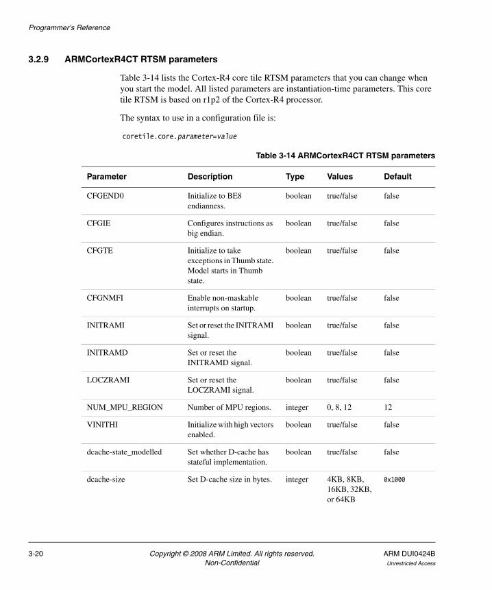
Programmer’s Reference
3.2.9 ARMCortexR4CT RTSM parameters
Table 3-14 lists the Cortex-R4 core tile RTSM parameters that you can change when you start the model. All listed parameters are instantiation-time parameters. This core tile RTSM is based on r1p2 of the Cortex-R4 processor.
The syntax to use in a configuration file is:
coretile.core.parameter=value
Table 3-14 ARMCortexR4CT RTSM parameters
Parameter Description Type Values Default
CFGEND0 Initialize to BE8 endianness.
boolean true/false false
CFGIE Configures instructions as big endian.
boolean true/false false
CFGTE Initialize to take exceptions in Thumb state. Model starts in Thumb state.
boolean true/false false
CFGNMFI Enable non-maskable interrupts on startup.
boolean true/false false
INITRAMI Set or reset the INITRAMI signal.
boolean true/false false
INITRAMD Set or reset the INITRAMD signal.
boolean true/false false
LOCZRAMI Set or reset the LOCZRAMI signal.
boolean true/false false
NUM_MPU_REGION Number of MPU regions. integer 0, 8, 12 12
VINITHI Initialize with high vectors enabled.
boolean true/false false
dcache-state_modelled Set whether D-cache has stateful implementation.
boolean true/false false
dcache-size Set D-cache size in bytes. integer 4KB, 8KB, 16KB, 32KB, or 64KB
0x1000
3-20 Copyright © 2008 ARM Limited. All rights reserved. ARM DUI0424BNon-Confidential Unrestricted Access
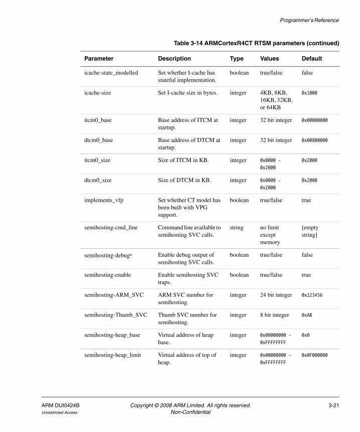
Programmer’s Reference
icache-state_modelled Set whether I-cache has stateful implementation.
boolean true/false false
icache-size Set I-cache size in bytes. integer 4KB, 8KB, 16KB, 32KB, or 64KB
0x1000
itcm0_base Base address of ITCM at startup.
integer 32 bit integer 0x00000000
dtcm0_base Base address of DTCM at startup.
integer 32 bit integer 0x00800000
itcm0_size Size of ITCM in KB. integer 0x0000 -
0x2000
0x2000
dtcm0_size Size of DTCM in KB. integer 0x0000 -
0x2000
0x2000
implements_vfp Set whether CT model has been built with VPG support.
boolean true/false true
semihosting-cmd_line Command line available to semihosting SVC calls.
string no limit except memory
[empty string]
semihosting-debuga Enable debug output of semihosting SVC calls.
boolean true/false false
semihosting-enable Enable semihosting SVC traps.
boolean true/false true
semihosting-ARM_SVC ARM SVC number for semihosting.
integer 24 bit integer 0x123456
semihosting-Thumb_SVC Thumb SVC number for semihosting.
integer 8 bit integer 0xAB
semihosting-heap_base Virtual address of heap base.
integer 0x00000000 -
0xFFFFFFFF
0x0
semihosting-heap_limit Virtual address of top of heap.
integer 0x00000000 -
0xFFFFFFFF
0x0F000000
Table 3-14 ARMCortexR4CT RTSM parameters (continued)
Parameter Description Type Values Default
ARM DUI0424B Copyright © 2008 ARM Limited. All rights reserved. 3-21Unrestricted Access Non-Confidential

Programmer’s Reference
The Cortex-R4 core tile RTSM also includes a GIC but this cannot be configured at instantiation time.
3.2.10 ARM1176CT RTSM parameters
Table 3-15 lists the ARM1176JZ-S™ core tile RTSM parameters that you can change when you start the model. All listed parameters are instantiation-time parameters except for num_interrupts, which is a run time parameter. This core tile RTSM is based on r0p4 of the ARM1176JZ-S processor.
The syntax to use in a configuration file is:
coretile.core.parameter=value
semihosting-stack_base Virtual address of base of descending stack.
integer 0x00000000 -
0xFFFFFFFF
0x10000000
semihosting-stack_limit Virtual address of stack limit.
integer 0x00000000 -
0xFFFFFFFF
0x0F0000000
vfp-enable_at_reset Enable coprocessor access and VFP at reset.b
boolean true/false false
a. Currently ignored.b. This is model specific behavior with no hardware equivalent.
Table 3-14 ARMCortexR4CT RTSM parameters (continued)
Parameter Description Type Values Default
Table 3-15 ARM1176CT RTSM parameters
Parameter Description Type Values Default
BIGENDINIT Initialize to ARMv5 big endian mode.
boolean true/false false
CP15SDISABLE Initialize to disable access to some CP15 registers.
boolean true/false false
INITRAM Initialize with ITCM0 enabled at address 0x0.
boolean true/false false
UBITINIT Initialize to ARMv6 unaligned behavior.
boolean true/false false
VINITHI Initialize with high vectors enabled.
boolean true/false false
3-22 Copyright © 2008 ARM Limited. All rights reserved. ARM DUI0424BNon-Confidential Unrestricted Access
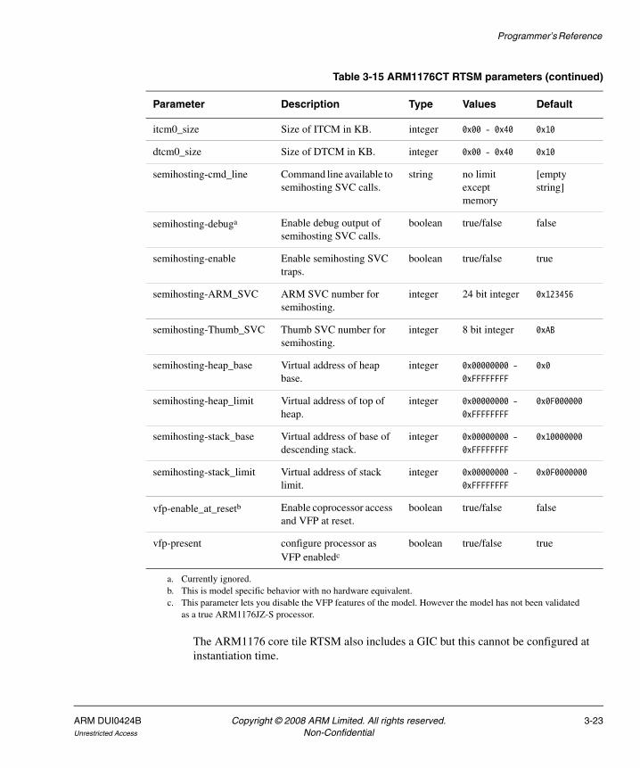
Programmer’s Reference
The ARM1176 core tile RTSM also includes a GIC but this cannot be configured at instantiation time.
itcm0_size Size of ITCM in KB. integer 0x00 - 0x40 0x10
dtcm0_size Size of DTCM in KB. integer 0x00 - 0x40 0x10
semihosting-cmd_line Command line available to semihosting SVC calls.
string no limit except memory
[empty string]
semihosting-debuga Enable debug output of semihosting SVC calls.
boolean true/false false
semihosting-enable Enable semihosting SVC traps.
boolean true/false true
semihosting-ARM_SVC ARM SVC number for semihosting.
integer 24 bit integer 0x123456
semihosting-Thumb_SVC Thumb SVC number for semihosting.
integer 8 bit integer 0xAB
semihosting-heap_base Virtual address of heap base.
integer 0x00000000 -
0xFFFFFFFF
0x0
semihosting-heap_limit Virtual address of top of heap.
integer 0x00000000 -
0xFFFFFFFF
0x0F000000
semihosting-stack_base Virtual address of base of descending stack.
integer 0x00000000 -
0xFFFFFFFF
0x10000000
semihosting-stack_limit Virtual address of stack limit.
integer 0x00000000 -
0xFFFFFFFF
0x0F0000000
vfp-enable_at_resetb Enable coprocessor access and VFP at reset.
boolean true/false false
vfp-present configure processor as VFP enabledc
boolean true/false true
a. Currently ignored.b. This is model specific behavior with no hardware equivalent.c. This parameter lets you disable the VFP features of the model. However the model has not been validated
as a true ARM1176JZ-S processor.
Table 3-15 ARM1176CT RTSM parameters (continued)
Parameter Description Type Values Default
ARM DUI0424B Copyright © 2008 ARM Limited. All rights reserved. 3-23Unrestricted Access Non-Confidential

Programmer’s Reference
3.2.11 ARM1136CT RTSM parameters
Table 3-16 lists the ARM1136JF-S™ core tile RTSM parameters that you can change when you start the model. All listed parameters are instantiation-time parameters except for num_interrupts, which is a run time parameter. This core tile RTSM is based on r1p1 of the ARM1136JF-S processor.
The syntax to use in a configuration file is:
coretile.core.parameter=value
Table 3-16 ARM1136CT RTSM parameters
Parameter Description Type Values Default
BIGENDINIT Initialize to ARMv5 big endian mode.
boolean true/false false
INITRAM Initialize with ITCM0 enabled at address 0x0.
boolean true/false false
UBITINIT Initialize to ARMv6 unaligned behavior.
boolean true/false false
VINITHI Initialize with high vectors enabled.
boolean true/false false
itcm0_size Size of ITCM in KB. integer 0x00 - 0x40 0x10
dtcm0_size Size of DTCM in KB. integer 0x00 - 0x40 0x10
semihosting-cmd_line Command line available to semihosting SVC calls.
string no limit except memory
[empty string]
semihosting-debuga Enable debug output of semihosting SVC calls.
boolean true/false false
semihosting-enable Enable semihosting SVC traps.
boolean true/false true
semihosting-ARM_SVC ARM SVC number for semihosting.
integer 24 bit integer 0x123456
semihosting-Thumb_SVC Thumb SVC number for semihosting.
integer 8 bit integer 0xAB
semihosting-heap_base Virtual address of heap base.
integer 0x00000000 -
0xFFFFFFFF
0x0
3-24 Copyright © 2008 ARM Limited. All rights reserved. ARM DUI0424BNon-Confidential Unrestricted Access

Programmer’s Reference
The ARM1136 core tile RTSM also includes a GIC but this cannot be configured at instantiation time.
3.2.12 ARM926CT RTSM parameters
Table 3-17 on page 3-26 lists the ARM926EJ-S™ core tile RTSM parameters that you can change when you start the model. All listed parameters are instantiation-time parameters except for num_interrupts, which is a run time parameter. This core tile RTSM is based on r0p5 of the ARM926EJ-S processor.
The syntax to use in a configuration file is:
coretile.core.parameter=value
semihosting-heap_limit Virtual address of top of heap.
integer 0x00000000 -
0xFFFFFFFF
0x0F000000
semihosting-stack_base Virtual address of base of descending stack.
integer 0x00000000 -
0xFFFFFFFF
0x10000000
semihosting-stack_limit Virtual address of stack limit.
integer 0x00000000 -
0xFFFFFFFF
0x0F0000000
vfp-enable_at_ resetb Enable coprocessor access and VFP at reset.
boolean true/false false
vfp-present configure processor as VFP enabledc
boolean true/false true
a. Currently ignored.b. This is model specific behavior with no hardware equivalent.c. This parameter lets you disable the VFP features of the model. However the model has not been validated as
a true ARM1136J-S processor.
Table 3-16 ARM1136CT RTSM parameters (continued)
Parameter Description Type Values Default
ARM DUI0424B Copyright © 2008 ARM Limited. All rights reserved. 3-25Unrestricted Access Non-Confidential
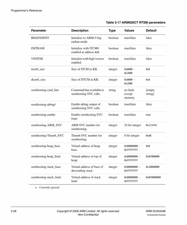
Programmer’s Reference
Table 3-17 ARM926CT RTSM parameters
Parameter Description Type Values Default
BIGENDINIT Initialize to ARMv5 big endian mode.
boolean true/false false
INITRAM Initialize with ITCM0 enabled at address 0x0.
boolean true/false false
VINITHI Initialize with high vectors enabled.
boolean true/false false
itcm0_size Size of ITCM in KB. integer 0x0000 -
0x2000
0x8
dtcm0_size Size of DTCM in KB. integer 0x0000 -
0x2000
0x8
semihosting-cmd_line Command line available to semihosting SVC calls.
string no limit except memory
[empty string]
semihosting-debuga Enable debug output of semihosting SVC calls.
boolean true/false false
semihosting-enable Enable semihosting SVC traps.
boolean true/false true
semihosting-ARM_SVC ARM SVC number for semihosting.
integer 24 bit integer 0x123456
semihosting-Thumb_SVC Thumb SVC number for semihosting.
integer 8 bit integer 0xAB
semihosting-heap_base Virtual address of heap base.
integer 0x00000000 -
0xFFFFFFFF
0x0
semihosting-heap_limit Virtual address of top of heap.
integer 0x00000000 -
0xFFFFFFFF
0x0F000000
semihosting-stack_base Virtual address of base of descending stack.
integer 0x00000000 -
0xFFFFFFFF
0x10000000
semihosting-stack_limit Virtual address of stack limit.
integer 0x00000000 -
0xFFFFFFFF
0x0F0000000
a. Currently ignored.
3-26 Copyright © 2008 ARM Limited. All rights reserved. ARM DUI0424BNon-Confidential Unrestricted Access
Programmer’s Reference
3.3 Differences between the EB hardware and the system model
The following sections describe features of the Emulation Baseboard hardware that are not implemented in the models or have significant differences in implementation:
• Features not present in the model
• Restrictions on the processor models on page 3-28
• Remapping and DRAM aliasing on page 3-31
• Dynamic memory characteristics on page 3-31
• Status and system control registers on page 3-32
• Generic Interrupt Controller on page 3-32
• GPIO2 on page 3-32
• Timing considerations on page 3-32.
3.3.1 Features not present in the model
The following features present on the hardware version of the Emulation Baseboard are not implemented in the system models:
• two wire serial bus interface
• character LCD interface
• smart card interface
• PCI controller configuration registers
• debug access port
• disk on chip
• configuration flash
• USB
• PISMO expansion memory
• PCI interface bus windows
• UART Modem handshake signals
• VGA support.
Note For more information on memory-mapped peripherals, see Memory map on page 3-2.
The following features present on the hardware version of the Emulation Baseboard are only partially implemented in the Real-Time System Models:
• Sound on page 3-28
• Dynamic memory controller on page 3-28.
ARM DUI0424B Copyright © 2008 ARM Limited. All rights reserved. 3-27Unrestricted Access Non-Confidential

Programmer’s Reference
Partial implementation means that some of the components are present but the functionality has not been fully modeled. If you use these features, they might not work as you expect. Check the model release notes for the latest information.
Sound
The EB RTSMs implement the PL041 AACI PrimeCell and the audio CODEC as in the EB hardware, but with a limited number of sample rates.
Dynamic memory controller
The dynamic memory controller, though modeled in the EB RTSMs, does not provide direct memory access to all peripherals. Only the audio and synchronous serial port interface components can be accessed through the DMC.
3.3.2 Restrictions on the processor models
Detailed information concerning what features are not fully implemented in the processor models included with the EB RTSMs can be found in separate documentation. See the Fast Model Portfolio CT Core Components Reference Manual. The following general restrictions apply to the Real-Time System Model implementations of ARM processors:
• The simulator does not model cycle timing. In aggregate, all instructions execute in one core master clock cycle, with the exception of Wait For Interrupt.
• Level 1 and level 2 caches are not part of the models for ARM Architecture v5 and 6 processors. Although cache control registers are included, in most cases they only enable you to check register access permissions. Cache flush operations are supported, but they have no effect. As a consequence, code that might fail on real hardware due to cache aliasing problems might run without problems on the EB RTSM.
• Write buffers are not modeled.
• Most aspects of TLB behavior are implemented in the models. However TLB memory attribute settings are ignored in Architecture v5 and v6 models, as they relate to cache and write buffer behavior. In Architecture v7 models, the TLB memory attribute settings are used when stateful cache is enabled.
• No MicroTLB is implemented.
• The ARMv6 architecture deprecates MMU sub-page permissions. These deprecated features are not supported by the simulator.
3-28 Copyright © 2008 ARM Limited. All rights reserved. ARM DUI0424BNon-Confidential Unrestricted Access

Programmer’s Reference
• A single memory access port is implemented. The port combines accesses for instruction, data, DMA and peripherals. Configuration of the peripheral port memory map register is ignored.
• All memory accesses are atomic and are performed in programmer’s view order. All transactions on the PVBus are a maximum of 32 bits wide. Unaligned accesses are always performed as byte transfers.
• Some instruction sequences are executed atomically, ahead of the component master clock, so that system time does advance during their execution. This can sometimes have an effect in sequential access of device registers where devices are expecting time to move on between each access.
• Interrupts are not taken at every instruction boundary.
• The semihosting-debug configuration parameter is ignored.
• Integration and test registers are not implemented.
• Only one CP14 debug coprocessor register is included, CP14 DSCR. The register reads 0 and ignores writes. Access to other CP14 registers causes an undefined instruction exception. To debug an RTSM you must use an external debugger.
• Breakpoints types supported directly by the model are:
— single address unconditional instruction breakpoints
— single address unconditional data breakpoints
— unconditional instruction address range breakpoints.
• Processor exception breakpoints are supported by pseudo-registers in the debugger. Setting an exception register to a non-zero value stops execution on entry to the associated exception vector.
• Performance counters are not implemented.
ARMCortexA9CT
The following additional restrictions apply to the Real-Time System Model for Cortex-A9 implementation of a Cortex-A9 processor:
• The RTSM includes built-in peripherals including a snoop control unit, distributed interrupt controller and an accelerator coherency port.
• The model implements L1 cache as architecturally defined. It does not implement L2 cache. If you require a L2 cache you can add a PL310 Level 2 Cache Controller component.
ARM DUI0424B Copyright © 2008 ARM Limited. All rights reserved. 3-29Unrestricted Access Non-Confidential

Programmer’s Reference
• Two 4GB regions of zero wait state virtual memory are seen by the model core, one as seen from secure mode and one as seen from normal mode.
• VFP and NEON instruction set execution on the model is not currently high performance.
ARMCortexA8CT
The following additional restrictions apply to the Real-Time System Model for Cortex-A8 implementation of a Cortex-A8 processor:
• The model uses a programmer’s view-accurate implementation of the L1 and L2 caches.
• Two 4GB regions of zero wait state virtual memory are seen by the model core, one as seen from secure mode and one as seen from normal mode.
• The PLE model is purely register-based and has no implemented behavior.
• VFP and NEON instruction set execution on the model is not currently high performance.
ARMCortexR4CT
The following additional restrictions apply to the Real-Time System Model for Cortex-R4 implementation of a Cortex-R4 processor:
• The model uses a programmer’s view-accurate implementation of cache.
• A single flat 4GB region of zero wait state memory is seen by the model core.
• VFP instruction set execution, and instructions in protection regions smaller than 1KB, are not currently high performance.
ARM1176CT
The following additional restrictions apply to the Real-Time System Model for ARM1176JZF implementation of an ARM1176JZF-S processor:
• Two 4GB regions of zero wait state virtual memory are seen by the model core, one as seen from secure mode and one as seen from normal mode.
• VFP instruction set execution on the model is not currently high performance.
• A simplified VIC is implemented. The interaction between the CPU and VIC is untimed once the interrupt is acknowledged.
3-30 Copyright © 2008 ARM Limited. All rights reserved. ARM DUI0424BNon-Confidential Unrestricted Access
Programmer’s Reference
ARM1136CT
The following additional restrictions apply to the Real-Time System Model for ARM1136JF implementation of an ARM1136JF-S processor:
• A single flat 4GB region of zero wait state memory is seen by the model core.
• VFP instruction set execution on the model is not currently high performance.
• A simplified VIC is implemented. The interaction between the CPU and VIC is untimed once the interrupt is acknowledged.
• System coprocessor registers pertaining to the TLB or MicroTLB read 0 and ignore writes.
ARM926CT
The following additional restrictions apply to the Real-Time System Model for ARM926JF implementation of an ARM926JF-S processor:
• A single flat 4GB region of zero wait state memory is seen by the model core.
3.3.3 Remapping and DRAM aliasing
The EB hardware provides considerable memory remap functionality. During this boot remapping, the bottom 64MB of the physical address map can be:
• NOR flash
• Static expansion memory.
As well as providing remap functionality, the hardware aliases all 256MB of system DRAM at 0x70000000.
Remapping does not typically apply to the system models. However, NOR flash is modelled and can be remapped. See Switch S8 on page 3-9.
In the memory map, memory regions that are not explicitly occupied by a peripheral or by memory are unmapped. This includes regions otherwise occupied by a peripheral that is not implemented, and those areas that are documented as reserved. Accessing these regions from the host processor results in the model presenting a warning.
3.3.4 Dynamic memory characteristics
The Emulation Baseboard hardware contains a PL340 DMC. This presents a configuration interface at address 0x10030000 in the memory map.
ARM DUI0424B Copyright © 2008 ARM Limited. All rights reserved. 3-31Unrestricted Access Non-Confidential
Programmer’s Reference
The system models configure a generic area of DRAM and does not model the PL340. This simplification helps speed the simulation.
3.3.5 Status and system control registers
For the hardware version of the Emulation Baseboard, the status and system control registers enable the processor to determine its environment and to control some on-board operations.
Note Most of the EB RTSM functionality is determined by its configuration on startup. See Configuring the EB Real-Time System Model on page 2-11.
All EB system registers have been implemented in the system model, except for SYS_TEST_OSC[4:0], the oscillator test registers. Registers that are not implemented function as memory and the values written to them do not alter the behavior of the model.
3.3.6 Generic Interrupt Controller
The Generic Interrupt Controller (GIC) provided with the EB RTSMs differs substantially from that in the current Emulation Board firmware. The programmer’s model of the newer device is largely backwards compatible. The model GIC is an implementation of the PL390 PrimeCell, for which comprehensive documentation is provided elsewhere. See PrimeCell Generic Interrupt Controller (PL390) Technical Reference Manual.
3.3.7 GPIO2
On the EB hardware, GPIO2 is dedicated to USB, a push button, and MCI status signals. USB and MCI are not implemented in the EB RTSMs, and no push button is modelled. The GPIO is therefore simply provided as another generic IO device.
3.3.8 Timing considerations
The Real-Time System Models provide you with an environment that lets you run software applications in a functionally-accurate simulation. However, because of the relative balance of fast simulation speed over timing accuracy, there are situations where the models might behave unexpectedly.
3-32 Copyright © 2008 ARM Limited. All rights reserved. ARM DUI0424BNon-Confidential Unrestricted Access

Programmer’s Reference
When your code interacts with real world devices like timers and keyboards, data arrives in the modeled device in real world, or wallclock, time, but simulation time could be running much faster than the wallclock. This means that a single keypress might be interpreted as several repeated keypresses, or a single mouse click incorrectly becomes a double click.
To work around this problem, the EB RTSMs supply the Rate Limit feature. Enabling Rate Limit, either using the Rate Limit button in the CLCD display, or the rate_limit-enable model instantiation parameter, forces the model to run at wallclock time. This avoids issues with two clocks running at significantly different rates. For interactive applications you are advised to enable Rate Limit.
ARM DUI0424B Copyright © 2008 ARM Limited. All rights reserved. 3-33Unrestricted Access Non-Confidential

Programmer’s Reference
3-34 Copyright © 2008 ARM Limited. All rights reserved. ARM DUI0424BNon-Confidential Unrestricted Access

Chapter 4 Using Model Components
This chapter describes how to use selected components provided with the Emulation Baseboard Real-Time System Models. These components are:
• Terminal on page 4-2
• Ethernet on page 4-5
• Virtual filesystem on page 4-12.
ARM DUI0424B Copyright © 2008 ARM Limited. All rights reserved. 4-1Unrestricted Access Non-Confidential
Using Model Components
4.1 Terminal
The Terminal component is a virtual component that allows UART data to be transferred between a TCP/IP socket on the host and a serial port on the target.
Note If you want to use the Terminal component with a Windows Vista client you must first install Telnet. The Telnet application is not installed on Windows Vista by default. You can download the application by following the instructions on the Microsoft website. Run a search for “Windows Vista Telnet” to find the Telnet FAQ page. To install Telnet:
1. Select Start → Control Panel → Programs and Features. This opens a window that lets you uninstall or change programs.
2. Select Turn Windows features on or off in the left hand side bar. This opens the Windows Features dialog. Select the Telnet Client check box.
3. Click OK. The installation of Telnet might take several minutes to complete.
A block diagram of one possible relationship between the target and host through the Terminal component is shown in Figure 4-1 on page 4-3. The TelnetTerminal block is what you configure when you define Terminal component parameters. The Virtual Machine is your EB RTSM.
4-2 Copyright © 2008 ARM Limited. All rights reserved. ARM DUI0424BNon-Confidential Unrestricted Access

Using Model Components
Figure 4-1 Terminal block diagram
On the target side, the console process invoked by your target OS relies upon a suitable driver being present. Such drivers are normally part of the OS kernel. The driver passes serial data through a UART. The data is forwarded to the TelnetTerminal component, which exposes a TCP/IP port to the world outside of the RTSM. This port can be connected to by, for example, a Telnet process on the host.
By default, the EB RTSM starts four telnet Terminals when the model is initialized. You can change the startup behavior for each of the four Terminals by modifying the corresponding component parameters. See Terminal parameters on page 3-11.
If the Terminal connection is broken, for example by closing a client telnet session, the port is re-opened on the host. This could have a different port number if the original one is no longer available. Before the first data access, you can connect a client of your choice to the network socket. If there is no existing connection when the first data access is made, and the start_telnet parameter is true, a host telnet session is started automatically.
Console
Driver
UART
TelnetTerminal
Telnet
TCP/IP
Serial
Virtual Machine
Target OS
Kernel
ARM DUI0424B Copyright © 2008 ARM Limited. All rights reserved. 4-3Unrestricted Access Non-Confidential
Using Model Components
The port number of a particular Terminal instance can be defined when the EB RTSM starts. The actual value of the port used by each Terminal is declared when it starts or restarts, and might not be the value you specified if the port is already in use. If you are using Model Shell, the port numbers are displayed in the host window in which you started the model.
You can start the Terminal component in one of two modes:
• Telnet mode
• Raw mode.
4.1.1 Telnet mode
In telnet mode, the Terminal component supports a subset of the RFC 854 protocol. This means that the Terminal participates in negotiations between the host and client concerning what is and is not supported, but flow control is not implemented.
4.1.2 Raw mode
Raw mode allows the byte stream to pass unmodified between the host and the target. This means that the Terminal component does not participate in initial capability negotiations between the host and client, and instead simply acts as a TCP/IP port. You can take advantage of this feature to directly connect to your target through the Terminal component.
4-4 Copyright © 2008 ARM Limited. All rights reserved. ARM DUI0424BNon-Confidential Unrestricted Access

Using Model Components
4.2 Ethernet
Note Ethernet is not supported on the EB RTSMs supplied with RealView Development Suite.
The EB RTSMs provide you with a virtual ethernet component. This is a model of the SMSC91C111 ethernet controller. You can configure the component to use a host ethernet port, or connect to an ethernet port on another host over TCP/IP. By default, the component starts as an unconnected ethernet port.
This section describes the following aspects of the EB RTSM ethernet component:
• Host requirements
• Target requirements on page 4-7
• Configuring ethernet in the model on page 4-7.
4.2.1 Host requirements
Before you can use the ethernet capability of the EB RTSM, you must first set up your host computer. Unless your applications have direct access to the host’s network devices, you need to install the nicserver proxy application. You might also need to install packet capture software.
nicserver
The nicserver application has two main functions:
• to provide a connection to the host packet capture facilities
• to provide a remote connection target.
Not all hosts allow non-administrator or non-root processes to access network devices. To work around this, you are given the nicserver application, which acts as a proxy. This workaround is most applicable on Linux, because typically only root has access to network devices. On Windows, you must have at least standard user permissions to use the nicserver application, as a restricted user is unable to access the necessary devices.
The nicserver application has uses other than as a proxy, however. For example, you can use nicserver, running on a different computer, as a target for your RTSM ethernet accesses.
ARM DUI0424B Copyright © 2008 ARM Limited. All rights reserved. 4-5Unrestricted Access Non-Confidential

Using Model Components
Note The nicserver application is included with the library supplied with Fast Models. If you have this product installed, the executable for supported environments in subdirectories of the %PVLIB_HOME%\lib directory.
The syntax for nicserver is:
nicserver [-a adapter] [-dedicated] [--help] [-l] [-n IP_address] [-p port] [-shared] [-version]
The command line arguments are:
-a adapter The host ethernet adapter on which to send and receive ethernet packets. Use a device name provided by the nicserver -l command. This name can be either part of the device text description, such as “wireless” or the manufacturer’s name, or a complete device ID, such as “eth0” or “\Device\NPF_{1FBF9456-7A62-43AB-B683-83F4142FB7E6}”. If the name is not unique, the first match as shown in the nicserver -l list is used.
-dedicated Run in non-promiscuous mode. Use this option if you are using the pipe transport to bind the nicserver instance to the specific RTSM that uses it.
--help Print out a summary of nicserver commands then quit.
-l List the available network adapters on the host then quit. Sample output from nicserver -l on Windows might look like this:
C:\> nicserver -lAvailable network adapters:\Device\NPF_{1FBF9456-7A62-43AB-B683-83F4142FB7E6} (NetworkCardInc Wireless Pro Network Connection)\Device\NPF_{924EB4D2-6588-438C-7115-DACFD1754EA2} (NetworkCardInc 100Gbit Ethernet Network Connection)
-n IP_address
Specify the IP address for nicserver to bind to. Together with the port, the IP address forms the TCP/IP socket for nicserver.
-p port Specify the port for nicserver to bind to. Together with the IP address, the port forms the TCP/IP socket for nicserver.
-shared Run in promiscuous mode, which is the default.
-version Print the nicserver version then quit.
You can start the nicserver application at a command prompt with, for example:
nicserver –p 7010 -n 192.168.0.42 -a NetworkCardInc
4-6 Copyright © 2008 ARM Limited. All rights reserved. ARM DUI0424BNon-Confidential Unrestricted Access
Using Model Components
This command starts nicserver in promiscuous mode with a TCP/IP socket of 192.168.0.42:7010 and uses the first available NetworkCardInc network controller on the host. If the command has succeeded, a message is output to confirm that nicserver is listening on a given IP address and port. To terminate nicserver, issue the normal SIGINT for your terminal, such as Ctrl + C. If the nicserver command fails, you are shown an error message, or you are returned straight to the command prompt. In either case, check your settings and try again.
On Linux, you might need to have root privileges to use nicserver. If this is the case, you must get an administrator to allow nicserver to be run with root permissions, using setuid.
On Windows, you must have the WinPcap driver installed to use nicserver. See Packet capture.
Packet capture
On Microsoft Windows the ethernet component depends on the WinPcap driver being installed. This allows the unique identification of ethernet devices if more than one is present. You can find the WinPcap distribution at http://www.winpcap.org/. Installing the binary distribution for Microsoft Windows installs the correct driver. A user with administrator privileges must install the software, and the end user must have at least Power User access privileges. Use WinPcap version 3.1 beta 4 or later.
On supported Linux systems, the Pcap packet capture library is present by default. No additional software is required on Linux for nicserver to work.
4.2.2 Target requirements
The EB RTSMs include a software implementation of the SMSC91C111 device. Your target OS must therefore include a driver for this specific device, and the kernel must be configured to use the SMSC chip. Operating systems that support the SMSC91C111 include WinCE, Symbian and Linux.
4.2.3 Configuring ethernet in the model
There are three ethernet component parameters. When you configure these parameters prior to starting the EB RTSM, you can specify which host interface to use, set the MAC address, and define whether promiscuous mode is enabled. These parameters are:
• interface on page 4-8
• mac_address on page 4-10
• promiscuous on page 4-11.
ARM DUI0424B Copyright © 2008 ARM Limited. All rights reserved. 4-7Unrestricted Access Non-Confidential

Using Model Components
Configuration file syntax for the ethernet component is given elsewhere in this document. See Ethernet parameters on page 3-9.
interface
The interface parameter setting in the EB RTSM ethernet component sets what host interface to use. When enabled, the ethernet component can use one of two transports, host or pipe.
A block diagram showing the host transport is shown in Figure 4-2.
Figure 4-2 Host transport block diagram
In the Figure, the Virtual Machine is your EB RTSM, and the SMSC91C111 block represents the configurable ethernet component. When using the host transport, the ethernet component communicates directly using TCP/IP with the packet capture component, Pcap. This means that your model must have sufficient permissions to access Pcap directly. This is normally not an issue on Windows if you have administrator rights. On Linux, you might find that you cannot use the host transport unless you have root privileges. This is not recommended for standard user applications. An alternative for Linux is to instead use the pipe transport.
Once data reaches the Ethernet component block, it can be handled in the same way as any other ethernet data. For example, you could connect to a nicserver session running on another host.
Target OS
Drivers
SMSC91C111
Pcap
Ethernet
Virtual Machine
TCP/IP
Operating System
4-8 Copyright © 2008 ARM Limited. All rights reserved. ARM DUI0424BNon-Confidential Unrestricted Access

Using Model Components
A block diagram, showing the situation if you use the pipe transport, is shown in Figure 4-3.
Figure 4-3 Pipe transport block diagram
The Virtual Machine represents your EB RTSM, with the SMSC91C111 block as the ethernet component interface to the world outside of the model. The pipe block provides a TCP/IP address and port with which the nicserver application communicates. This lets you disregard the specifics of the network hardware on your host system, and instead rely on nicserver to route communications appropriately. The nicserver application here acts as a proxy between you and the real network hardware, and removes the need to have direct permission to use network resources. This might be particularly useful on Linux platforms, where nicserver can be given root permissions but still be run by a user. The pipe block can communicate with a nicserver application running on a completely different computer from that on which the EB RTSM is running, as the connection is made over TCP/IP.
Target OS
Drivers
SMSC91C111
Pcap
Ethernet
Virtual Machine
Pipe
TCP/IP
nicserver
Operating System
ARM DUI0424B Copyright © 2008 ARM Limited. All rights reserved. 4-9Unrestricted Access Non-Confidential

Using Model Components
The EB RTSM ethernet interface parameter must be configured with one of the three following values:
disabled Implement the ethernet component as though no cable were connected. This means you can send packets to the component but they are not sent elsewhere. This is the default state.
host:controller
The controller is the first host ethernet controller that matches the string specified. On Linux, you can normally use the name of a specific adapter, such as eth0. On Windows, matters are more complex because you might have two network adaptors with similar names.
If controller is set to “NetworkCardInc”, the first match in the nicserver list is used, if there is more than one device with that string in the name. If you want to use a different controller, you must specify as much of the name as necessary for a unique match. Alternatively you could use the device ID supplied by nicserver.
Use the host:controller setting if you want the EB RTSM ethernet component to connect directly to an ethernet adaptor on the host computer.
pipe:address:port
The numeric address and port values are those of the nicserver application, if used on the host. See nicserver on page 4-5. Use this setting if you want the EB RTSM ethernet component to connect to a virtual network interface card running on the host computer.
mac_address
You must define whether the MAC address of the ethernet component is to be either a fixed or a random value.
Specifying the MAC address in a format analogous to the default value of 00:01:02:03:04:05 defines a static MAC address that does not change from one model invocation to the next.
Specifying the MAC address as auto generates a random local MAC address, with bit 1 set and bit 0 clear. A different IP address is allocated each time the simulator is reset. The chances of the address clashing with an existing MAC address are small but you are discouraged from using this method if IP addresses are being allocated automatically by a DHCP server.
4-10 Copyright © 2008 ARM Limited. All rights reserved. ARM DUI0424BNon-Confidential Unrestricted Access

Using Model Components
promiscuous
The ethernet component starts in promiscuous mode by default. This means that it receives all network traffic, even that which is not specifically addressed to the device. You must use this mode when you are using a single network device for multiple MAC addresses, for example if you are sharing the same network card between your host OS and the EB RTSM ethernet component.
An example ethernet configuration
As an example, consider that you are using the nicserver application and have set it up to listen on port 7010 and have an IP address of 192.168.0.42. You want the ethernet device on the EB RTSM to have a static MAC address of 0012AB9CE830, and start in promiscuous mode. The syntax to use in a configuration file would be:
baseboard.smsc_91c111_0.interface=pipe:192.168.0.42:7010baseboard.smsc_91c111_0.mac_address=00:12:AB:9C:E8:30baseboard.smsc_91c111_0.promiscuous=T
If instead you are using a GUI configuration interface, you need to modify the parameters corresponding to those given in the configuration file syntax example.
ARM DUI0424B Copyright © 2008 ARM Limited. All rights reserved. 4-11Unrestricted Access Non-Confidential
Using Model Components
4.3 Virtual filesystem
The Virtual FileSystem (VFS) allows your target to access parts of a host filesystem. This access is achieved through a target OS-specific driver and a memory mapped device called the MessageBox. When using the VFS, access to the host filesystem is analogous to access to a shared network drive, and can be expected to behave in the same way.
This section contains the following sections:
• VFS operations
• Using the VFS with a pre-built RTSM on page 4-13.
This section does not cover the process for adding the VFS component to your model system, but instead on how the end user interacts with the VFS.
Note If you require building your own RTSM system that includes the VFS, see the Fast Model Portfolio Peripheral Components Reference Manual and WritingADriver.txt file in %PVLIB_HOME%\VFS\docs\.
4.3.1 VFS operations
The VFS supports the following filesystem operations:
getattr retrieves metadata for the file, directory or symbolic link
mkdir creates a new directory
remove removes a file, directory or symbolic link
rename renames a file, directory or symbolic link
rmdir removes an empty directory
setattr sets metadata for the file, directory or symbolic link.
Note setattr is not currently implemented.
Symbolic link functions are implemented to support symbolic links in Linux, but they are not currently implemented. File permissions are defined but not implemented.
The VFS supports the following mount points:
closemounts frees the iterator handle returned from openmounts
openmounts retrieves an iterator handle for the list of available mounts
4-12 Copyright © 2008 ARM Limited. All rights reserved. ARM DUI0424BNon-Confidential Unrestricted Access
Using Model Components
readmounts reads one entry from the mount iterator ID.
The VFS supports the following directory iterators:
closedir frees a directory iterator handle retrieved by opendir
opendir retrieves an iterator handle for the directory specified
readdir reads the next entry from the directory iterator.
Note Datestamps returned are in milliseconds elapsed since the VFS epoch of January 01 1970 00:00 UTC and are host datestamps. The host datestamp might be in the future relative to the simulated OS datestamp.
The VFS supports the following file operations:
closefile frees a handle opened with openfile
filesync forces the host OS to flush all file data to persistent storage
getfilesize returns the current size of a file, in bytes
openfile returns a handle to the file specified
readfile reads a block of data from a file
setfilesize sets the current size of a file in bytes, either by truncating, or extending the file with zeroes
writefile writes a block of data to a file.
4.3.2 Using the VFS with a pre-built RTSM
The VFS is added to an RTSM at build time. The supplied EB RTSMs include the necessary VFS components. This allows you to run a Linux image, for example, on the EB RTSM and access the filesystem running on your computer.
Mount names
Once the target OS is running, create a mount point, such as /mnt/host. For example, on a Linux target, use the mount command as follows:
mount -t vmfs A /mnt/host
You can then access the host filesystem from the target OS through a supported filesystem operation. See VFS operations on page 4-12.
ARM DUI0424B Copyright © 2008 ARM Limited. All rights reserved. 4-13Unrestricted Access Non-Confidential

Using Model Components
Note If you have the Fast Models product installed, see also the ReadMe.txt file in the %PVLIB_HOME%\VFS2\linux\ directory.
Path names
All path names must be fully qualified paths of the form:
mountpoint:/path/to/object
4-14 Copyright © 2008 ARM Limited. All rights reserved. ARM DUI0424BNon-Confidential Unrestricted Access
Glossary
This glossary lists abbreviations used in this document or the Emulation Baseboard User Guide.
AACI Advanced Audio CODEC Interface.
AHB™ Advanced High-performance Bus. The ARM open standard for on-chip buses.
AMBA® Advanced Microcontroller Bus Architecture.
APB Advanced Peripheral Bus. The ARM open standard for peripheral buses. This design is optimized for low power and minimal interface complexity.
AXI™ Advanced eXtensible Interface. The ARM open standard for high-performance and high-frequency buses.
CADI Cycle Accurate Debug Interface. A C++ API supporting interface capabilities for re-targetable, multi-core debug integration.
CLCD Color Liquid-Crystal Display.
CODEC COder DECoder for converting between analog and digital audio signals.
CXSM Cycle approXimate System Model.
ARM DUI0424B Copyright © 2008 ARM Limited. All rights reserved. Glossary-1Unrestricted Access Non-Confidential

Glossary
DOC Disk-On-Chip. A non-volatile flash memory device with an interface that simplifies file accesses. Also called NAND flash referring to the logic gates used internally. The memory can only be accessed sequentially in blocks.
DMC Dynamic Memory Controller.
DMA Direct Memory Access.
DRAM Dynamic Random Access Memory.
DSR Data Set Ready, a UART flow-control signal.
DTR Data Terminal Ready, a UART flow-control signal.
EB RealView® Emulation Baseboard. A hardware development platform that supports various Core Tiles and FPGA tiles.
GIC Generic Interrupt Controller.
GPIO General Purpose Input/Output.
Integrator®/CP Integrator Compact Platform.
I/O Input/Output.
KMI Keyboard/Mouse Interface.
LCD Liquid Crystal Display.
LED Light Emitting Diode.
MAC Media Access Control. A layer in the Ethernet specification.
MCI MultiMedia Card Interface.
MMC MultiMedia Card.
NAND flash Non-volatile memory. NAND refers to the type of logic gate used internally. See DOC.
NOR flash Non-volatile memory. NOR refers to the type of logic gate used internally. Any memory address can be accessed randomly.
PCI Peripheral Component Interconnect. A computer bus for attaching peripherals.
PHY PHYsical layer. The layer in the Ethernet specification that describes the physical interface.
PISMO Platform Independent Storage Module. Memory specification for plug in memory modules.
PLL Phase-Locked Loop, a type of programmable oscillator.
Glossary-2 Copyright © 2008 ARM Limited. All rights reserved. ARM DUI0424BNon-Confidential Unrestricted Access
Glossary
RAM Random Access Memory.
RTC Real-Time Clock.
RTSM Real-Time System Model.
RVD RealView Debugger.
SRAM Static Random Access Memory.
SCI Smart Card Interface.
SD Secure Digital memory card specification.
SMC Static Memory Controller.
SSP Synchronous Serial Port.
TCM Tightly Coupled Memory. Memory present inside the test chip that typically runs at or near the processor speed.
UART Universal Asynchronous Receiver/Transmitter.
USB Universal Serial Bus.
VGA Video Graphics Array.
ARM DUI0424B Copyright © 2008 ARM Limited. All rights reserved. Glossary-3Unrestricted Access Non-Confidential

Glossary
Glossary-4 Copyright © 2008 ARM Limited. All rights reserved. ARM DUI0424BNon-Confidential Unrestricted Access