REALprojek-BACK PRESSURE
36
PRESSURE DISTRIBUTION IN CONVERGING-DIVERGING NOZZLE OBJECTIVE: to observe the pressure distribution in the converging-diverging nozzle, to observe the back pressure and the effect of it. To investigate pressure distribution and mass flow rate in nozzles.
-
Upload
telagajernih -
Category
Documents
-
view
219 -
download
0
Transcript of REALprojek-BACK PRESSURE
8/7/2019 REALprojek-BACK PRESSURE
http://slidepdf.com/reader/full/realprojek-back-pressure 1/36
PRESSURE DISTRIBUTION IN
CONVERGING-DIVERGING NOZZLE
OBJECTIVE: to observe the pressure
distribution in the
converging-divergingnozzle,
to observe the backpressure and the effect of
it. To investigate pressure
distribution and mass flowrate in nozzles.
8/7/2019 REALprojek-BACK PRESSURE
http://slidepdf.com/reader/full/realprojek-back-pressure 2/36
PRESSURE DISTRIBUTION INCONVERGING-DIVERGINGNOZZLE
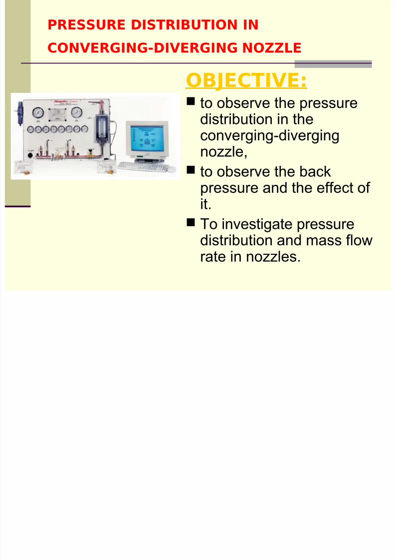
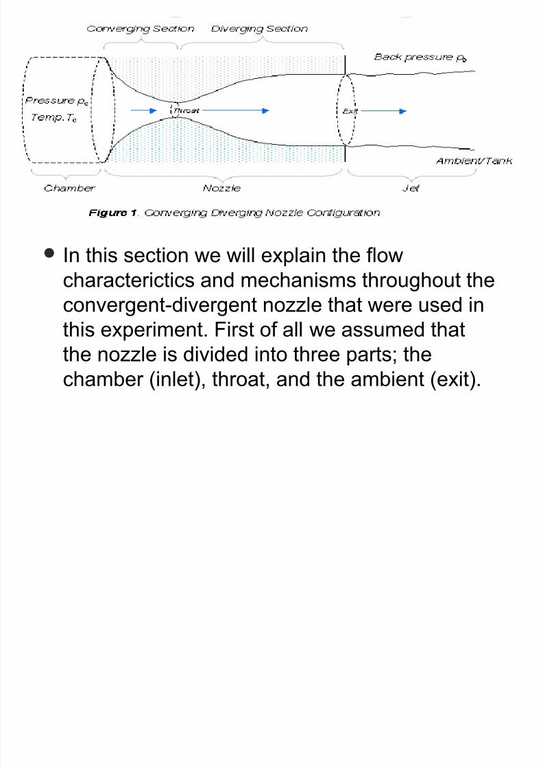
The usual configuration for a converging diverging(CD) nozzle is shown in the figure. Gas flows throughthe nozzle from a region of high pressure (usuallyreferred to as the chamber) to one of low pressure(referred to as the ambient or tank). The chamber isusually big enough so that any flow velocities here
are negligible. The pressure here is denoted by thesymbol pc. Gas flows from the chamber into theconverging portion of the nozzle, past the throat,through the diverging portion and then exhausts intothe ambient as a jet. The pressure of the ambient isreferred to as the 'back pressure' and given thesymbol pb.
8/7/2019 REALprojek-BACK PRESSURE
http://slidepdf.com/reader/full/realprojek-back-pressure 3/36
8/7/2019 REALprojek-BACK PRESSURE
http://slidepdf.com/reader/full/realprojek-back-pressure 4/36
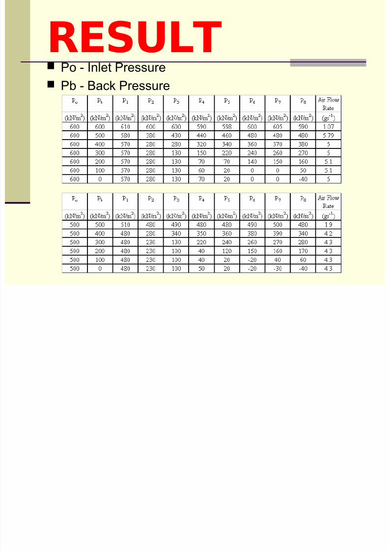
RESULT Po - Inlet Pressure Pb - Back Pressure
8/7/2019 REALprojek-BACK PRESSURE
http://slidepdf.com/reader/full/realprojek-back-pressure 5/36
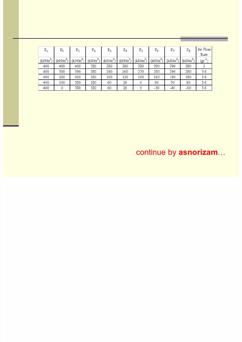
continue by asnorizam…

8/7/2019 REALprojek-BACK PRESSURE
http://slidepdf.com/reader/full/realprojek-back-pressure 6/36
8/7/2019 REALprojek-BACK PRESSURE
http://slidepdf.com/reader/full/realprojek-back-pressure 7/36
BACK PRESSURE EXPERIMENT
8/7/2019 REALprojek-BACK PRESSURE
http://slidepdf.com/reader/full/realprojek-back-pressure 8/36
OBJECTIVE
The aim of the experiment is to observethe pressure distribution in the
converging-diverging nozzle with three
different back pressure. The results andthe graphs plotted will be compared withthe theory. The experiment was beenperformed in under design,underexpended and over expendedconditions.

8/7/2019 REALprojek-BACK PRESSURE
http://slidepdf.com/reader/full/realprojek-back-pressure 9/36

8/7/2019 REALprojek-BACK PRESSURE
http://slidepdf.com/reader/full/realprojek-back-pressure 10/36
8/7/2019 REALprojek-BACK PRESSURE
http://slidepdf.com/reader/full/realprojek-back-pressure 11/36
CONCEPT IN BACK PRESSURE
8/7/2019 REALprojek-BACK PRESSURE
http://slidepdf.com/reader/full/realprojek-back-pressure 12/36
In this section we will explain the flow
characterictics and mechanisms throughout theconvergent-divergent nozzle that were used in
this experiment. First of all we assumed that
the nozzle is divided into three parts; the
chamber (inlet), throat, and the ambient (exit).
8/7/2019 REALprojek-BACK PRESSURE
http://slidepdf.com/reader/full/realprojek-back-pressure 13/36
8/7/2019 REALprojek-BACK PRESSURE
http://slidepdf.com/reader/full/realprojek-back-pressure 14/36
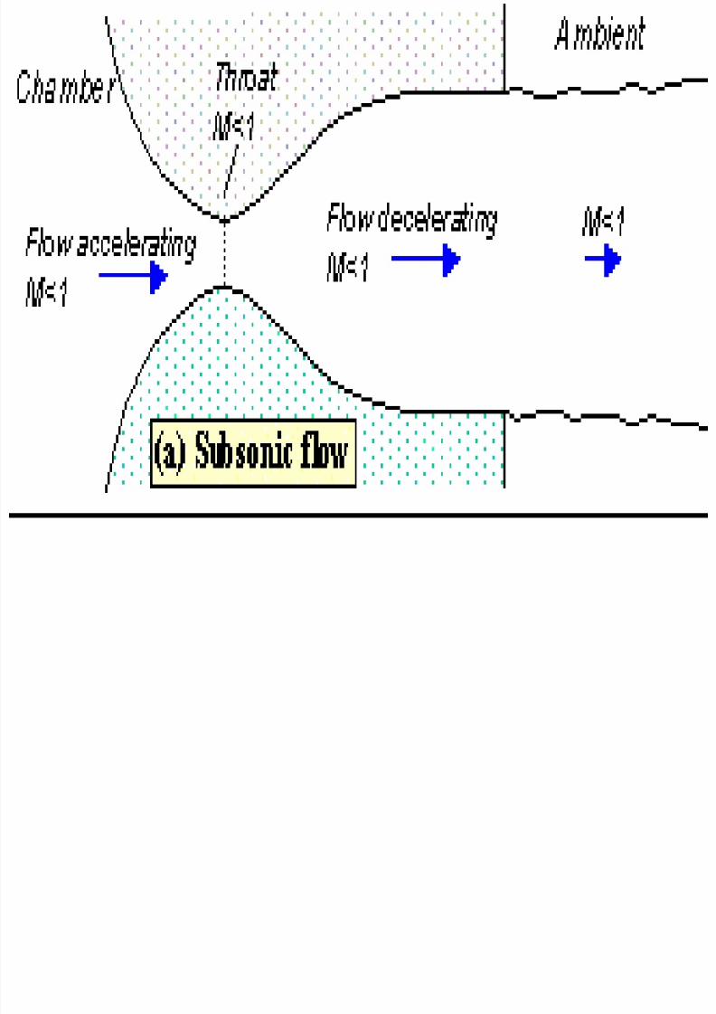
Figure shows the flow through the nozzle when
it is completely subsonic.
The flow accelerates out of the chamber.
Its maximum (subsonic) speed at the throat.
The flow then decelerates through the divergingsection and exhausts into the ambient as a
subsonic jet.
Lowering the back pressure in this stateincreases the flow speed everywhere in the
nozzle.
8/7/2019 REALprojek-BACK PRESSURE
http://slidepdf.com/reader/full/realprojek-back-pressure 15/36
8/7/2019 REALprojek-BACK PRESSURE
http://slidepdf.com/reader/full/realprojek-back-pressure 16/36
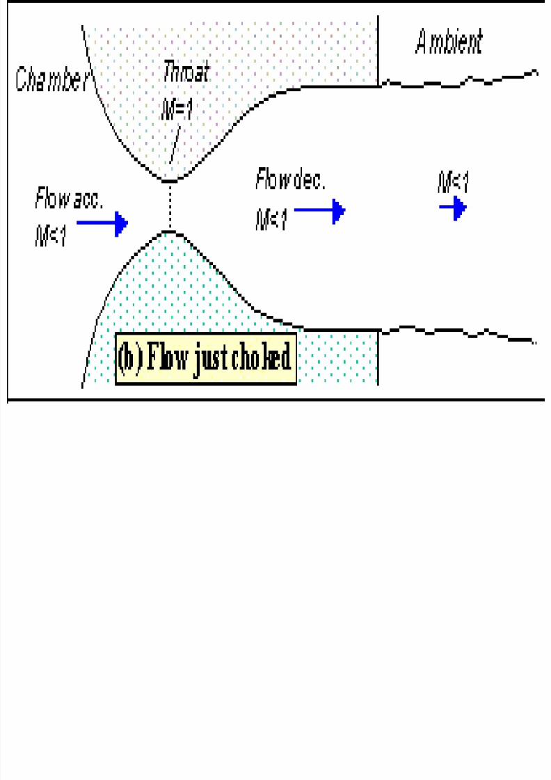
Lower it far enough and we eventually get to
the situation shown in figure 3.
The flow pattern is exactly the same as in
subsonic flow
Except that the flow speed at the throat has just
reached Mach 1.
Flow through the nozzle is now choked since
further reductions in the back pressure can't
move the point of M=1 away from the throat.
However, the flow pattern in the diverging
section does change as you lower the back
pressure further.
8/7/2019 REALprojek-BACK PRESSURE
http://slidepdf.com/reader/full/realprojek-back-pressure 17/36
A b i l d th fl i f i fl
8/7/2019 REALprojek-BACK PRESSURE
http://slidepdf.com/reader/full/realprojek-back-pressure 18/36
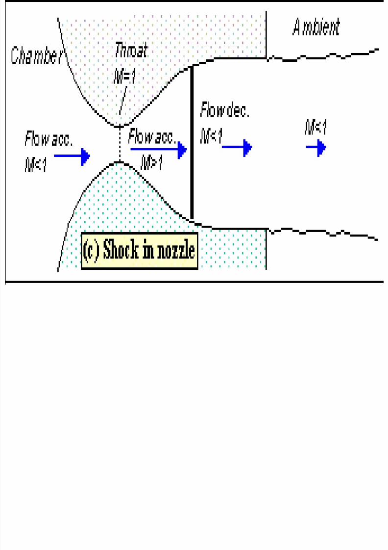
As pb is lowered the flow a region of supersonic flowforms just downstream of the throat.
Unlike a subsonic flow, the supersonic flow
accelerates as the area gets bigger.This region of supersonic acceleration is terminated by
a normal shock wave.The shock wave produces a near-instantaneous
deceleration of the flow to subsonic speed.This subsonic flow then decelerates through the
remainder of the diverging section and exhausts as asubsonic jet.
In this regime if we lower or raise the back pressurewe increase or decrease the length of supersonic flowin the diverging section before the shock wave.

8/7/2019 REALprojek-BACK PRESSURE
http://slidepdf.com/reader/full/realprojek-back-pressure 19/36
8/7/2019 REALprojek-BACK PRESSURE
http://slidepdf.com/reader/full/realprojek-back-pressure 20/36
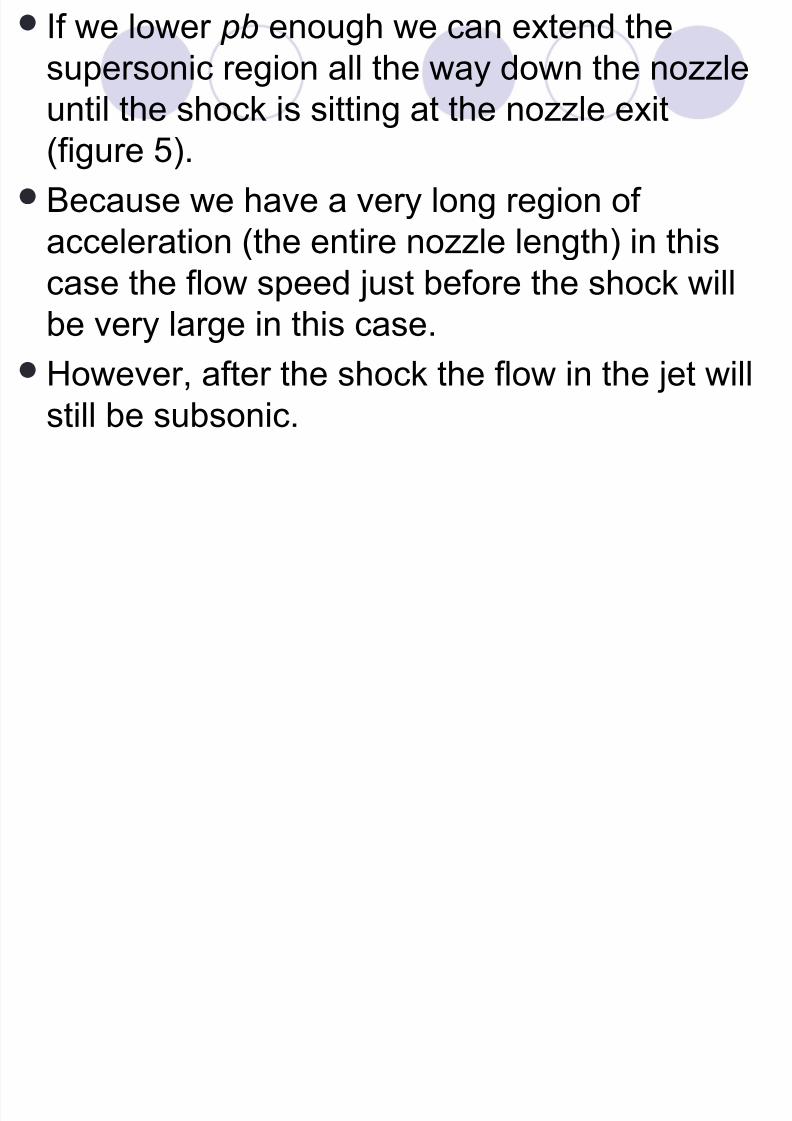
If we lower pb enough we can extend the
supersonic region all the way down the nozzle
until the shock is sitting at the nozzle exit
(figure 5).
Because we have a very long region of
acceleration (the entire nozzle length) in this
case the flow speed just before the shock willbe very large in this case.
However, after the shock the flow in the jet will
still be subsonic.
8/7/2019 REALprojek-BACK PRESSURE
http://slidepdf.com/reader/full/realprojek-back-pressure 21/36
L i th b k f th th h k
8/7/2019 REALprojek-BACK PRESSURE
http://slidepdf.com/reader/full/realprojek-back-pressure 22/36
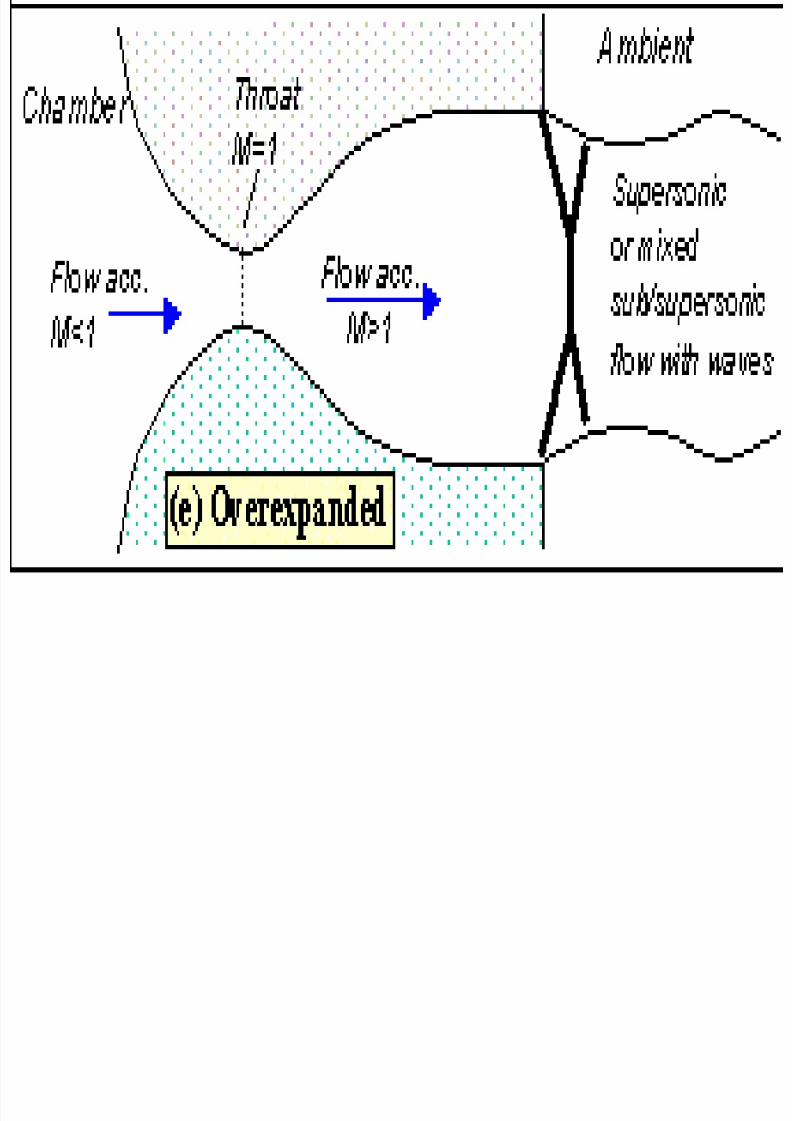
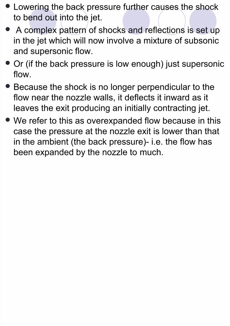
Lowering the back pressure further causes the shock
to bend out into the jet.
A complex pattern of shocks and reflections is set up
in the jet which will now involve a mixture of subsonicand supersonic flow.
Or (if the back pressure is low enough) just supersonic
flow.
Because the shock is no longer perpendicular to the
flow near the nozzle walls, it deflects it inward as it
leaves the exit producing an initially contracting jet.
We refer to this as overexpanded flow because in thiscase the pressure at the nozzle exit is lower than that
in the ambient (the back pressure)- i.e. the flow has
been expanded by the nozzle to much.
8/7/2019 REALprojek-BACK PRESSURE
http://slidepdf.com/reader/full/realprojek-back-pressure 23/36
A f th l i f th b k
8/7/2019 REALprojek-BACK PRESSURE
http://slidepdf.com/reader/full/realprojek-back-pressure 24/36
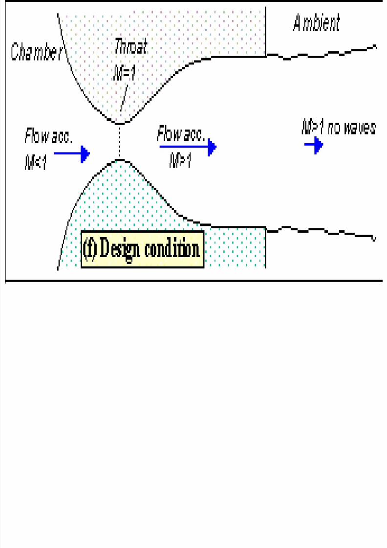
A further lowering of the back pressure
changes and weakens the wave pattern in the
jet.
Eventually we will have lowered the back
pressure enough so that it is now equal to the
pressure at the nozzle exit.
In this case, the waves in the jet disappear
altogether
The jet will be uniformly supersonic.
This situation, since it is often desirable, is
referred to as the 'design condition'.
8/7/2019 REALprojek-BACK PRESSURE
http://slidepdf.com/reader/full/realprojek-back-pressure 25/36
Fi ll if l th b k
8/7/2019 REALprojek-BACK PRESSURE
http://slidepdf.com/reader/full/realprojek-back-pressure 26/36
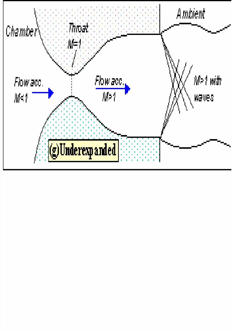
Finally, if we lower the back pressure even
further we will create a new imbalance between
the exit and back pressures.
Exit pressure greater than back pressure
In this situation (called 'underexpanded')
what we call expansion waves (that producegradual turning and acceleration in the jet) form
at the nozzle exit.
Initially turning the flow at the jet edges outward
in a plume and setting up a different type of
complex wave pattern.
8/7/2019 REALprojek-BACK PRESSURE
http://slidepdf.com/reader/full/realprojek-back-pressure 27/36

8/7/2019 REALprojek-BACK PRESSURE
http://slidepdf.com/reader/full/realprojek-back-pressure 28/36
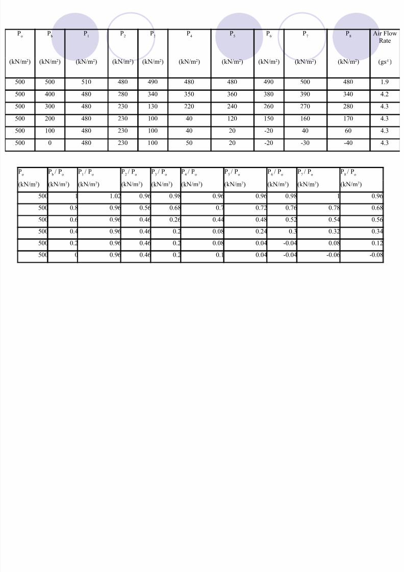
Po
Pb
P1
P2
P3
P4
P5
P6
P7
P8
Air FlowRate
(kN/m2) (kN/m2) (kN/m2) (kN/m2) (kN/m2) (kN/m2) (kN/m2) (kN/m2) (kN/m2) (kN/m2) (gs-1)
400 400 400 380 380 380 380 390 390 380 2
400 300 390 180 240 260 270 280 290 280 3.6
400 200 400 180 160 120 160 160 180 180 3.6
400 100 380 180 60 20 0 60 70 80 3.6
400 0 380 180 60 20 0 -30 -40 -60 3.6
Po
Pb/ P
oP
1/ P
oP
2/ P
oP
3/ P
oP
4/ P
oP
5/ P
oP
6/ P
oP
7/ P
oP
8/ P
o
(kN/m2) (kN/m2) (kN/m2) (kN/m2) (kN/m2) (kN/m2) (kN/m2) (kN/m2) (kN/m2) (kN/m2)
400 1 1 0.95 0.95 0.95 0.95 0.975 0.975 0.95
400 0.75 0.975 0.45 0.6 0.65 0.675 0.7 0.725 0.7
400 0.5 1 0.45 0.4 0.3 0.4 0.4 0.45 0.45
400 0.25 0.95 0.45 0.15 0.05 0 0.15 0.175 0.2
400 0 0.95 0.45 0.15 0.05 0 -0.075 -0.1 -0.15
8/7/2019 REALprojek-BACK PRESSURE
http://slidepdf.com/reader/full/realprojek-back-pressure 29/36
1 2 3 4 5 6 7 8-0.2
0
0.2
0.4
0.6
0.8
1
1.2
Position Of Pressure Gauges Along Nozzle
Px/P
in
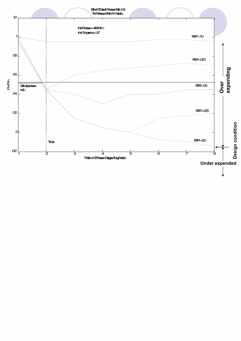
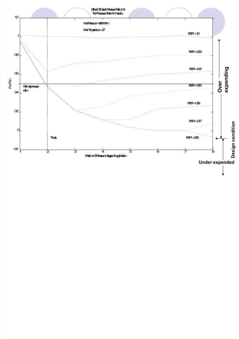
Effect Of Overall Pressure Ratio On
The "Pressure Profile" In Nozzle
Inlet Pressure = 400 kN/m
Inlet Temperature = 27Pb/Pi = 1.0
Pb/Pi = 0.75
Pb/Pi = 0.5
Pb/Pi = 0.25
Pb/Pi = 0.0
Critical pressure
ratio
Throat
Over
expe
ndi n
g
Designc
ondition
Under expended
8/7/2019 REALprojek-BACK PRESSURE
http://slidepdf.com/reader/full/realprojek-back-pressure 30/36
Po
Pb
P1
P2
P3
P4
P5
P6
P7
P8
Air FlowRate
(kN/m2) (kN/m2) (kN/m2) (kN/m2) (kN/m2) (kN/m2) (kN/m2) (kN/m2) (kN/m2) (kN/m2) (gs-1)
500 500 510 480 490 480 480 490 500 480 1.9
500 400 480 280 340 350 360 380 390 340 4.2
500 300 480 230 130 220 240 260 270 280 4.3
500 200 480 230 100 40 120 150 160 170 4.3
500 100 480 230 100 40 20 -20 40 60 4.3
500 0 480 230 100 50 20 -20 -30 -40 4.3
Po
Pb/ P
oP
1/ P
oP
2/ P
oP
3/ P
oP
4/ P
oP
5/ P
oP
6/ P
oP
7/ P
oP
8/ P
o
(kN/m2) (kN/m2) (kN/m2) (kN/m2) (kN/m2) (kN/m2) (kN/m2) (kN/m2) (kN/m2) (kN/m2)
500 1 1.02 0.96 0.98 0.96 0.96 0.98 1 0.96
500 0.8 0.96 0.56 0.68 0.7 0.72 0.76 0.78 0.68500 0.6 0.96 0.46 0.26 0.44 0.48 0.52 0.54 0.56
500 0.4 0.96 0.46 0.2 0.08 0.24 0.3 0.32 0.34
500 0.2 0.96 0.46 0.2 0.08 0.04 -0.04 0.08 0.12
500 0 0.96 0.46 0.2 0.1 0.04 -0.04 -0.06 -0.08
8/7/2019 REALprojek-BACK PRESSURE
http://slidepdf.com/reader/full/realprojek-back-pressure 31/36
1 2 3 4 5 6 7 8-0.2
0
0.2
0.4
0.6
0.8
1
1.2
Position Of Pressure Gauges Along Nozzle
Px/P
in
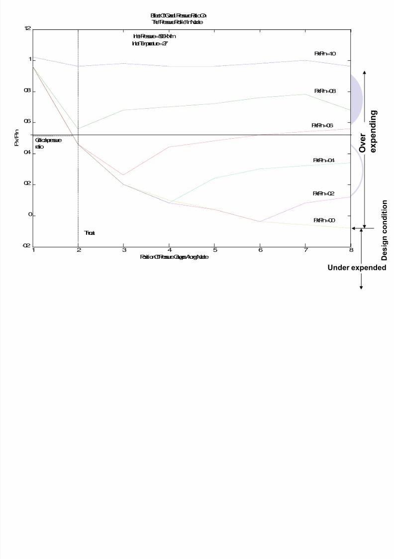
Effect Of Overall Pressure Ratio On
The "Pressure Profile" In Nozzle
Inlet Pressure = 500 kN/m
Inlet Temperature = 27
Px/Pin = 1.0
Px/Pin = 0.8
Px/Pin = 0.6
Px/Pin = 0.4
Px/Pin = 0.2
Px/Pin = 0.0
Critical pressure
ratio
Throat
Over
expe
ndi n
g
Designc
ondition
Under expended
8/7/2019 REALprojek-BACK PRESSURE
http://slidepdf.com/reader/full/realprojek-back-pressure 32/36
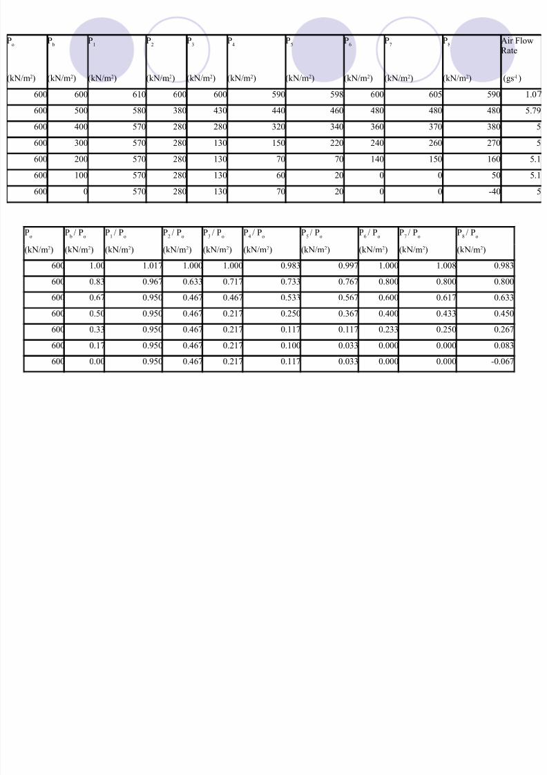
Po
Pb
P1
P2
P3
P4
P5
P6
P7
P8
Air FlowRate
(kN/m2) (kN/m2) (kN/m2) (kN/m2) (kN/m2) (kN/m2) (kN/m2) (kN/m2) (kN/m2) (kN/m2) (gs-1)
600 600 610 600 600 590 598 600 605 590 1.0600 500 580 380 430 440 460 480 480 480 5.79
600 400 570 280 280 320 340 360 370 380 5
600 300 570 280 130 150 220 240 260 270 5
600 200 570 280 130 70 70 140 150 160 5.1
600 100 570 280 130 60 20 0 0 50 5.1
600 0 570 280 130 70 20 0 0 -40 5
Po
Pb/ P
oP
1/ P
oP
2/ P
oP
3/ P
oP
4/ P
oP
5/ P
oP
6/ P
oP
7/ P
oP
8/ P
o
(kN/m2) (kN/m2) (kN/m2) (kN/m2) (kN/m2) (kN/m2) (kN/m2) (kN/m2) (kN/m2) (kN/m2)
600 1.00 1.017 1.000 1.000 0.983 0.997 1.000 1.008 0.983
600 0.83 0.967 0.633 0.717 0.733 0.767 0.800 0.800 0.800600 0.67 0.950 0.467 0.467 0.533 0.567 0.600 0.617 0.633
600 0.50 0.950 0.467 0.217 0.250 0.367 0.400 0.433 0.450
600 0.33 0.950 0.467 0.217 0.117 0.117 0.233 0.250 0.267
600 0.17 0.950 0.467 0.217 0.100 0.033 0.000 0.000 0.083
600 0.00 0.950 0.467 0.217 0.117 0.033 0.000 0.000 -0.067
8/7/2019 REALprojek-BACK PRESSURE
http://slidepdf.com/reader/full/realprojek-back-pressure 33/36
1 2 3 4 5 6 7 8-0.2
0
0.2
0.4
0.6
0.8
1
1.2
Position Of Pressure Gauges Along Nozzle
Px/P
in
Effect Of Overall Pressure Ratio On
The "Pressure Profile" In Nozzle
Inlet Pressure = 600 kN/m
Inlet Temperature = 27Pb/Pi = 1.0
Pb/Pi = 0.83
Pb/Pi = 0.67
Pb/Pi = 0.50
Pb/Pi = 0.33
Pb/Pi = 0.17
Pb/Pi = 0.00
Critical pressure
ratio
Throat
Over
expendi n
g
Designc
onditio
n
Under expended
8/7/2019 REALprojek-BACK PRESSURE
http://slidepdf.com/reader/full/realprojek-back-pressure 34/36
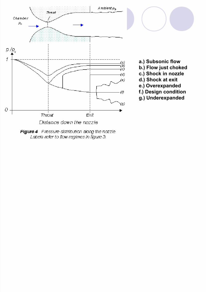
a.) Subsonic flow
b.) Flow just choked
c.) Shock in nozzled.) Shock at exit
e.) Overexpanded
f.) Design condition
g.) Underexpanded
8/7/2019 REALprojek-BACK PRESSURE
http://slidepdf.com/reader/full/realprojek-back-pressure 35/36
1 2 3 4 5 6 7-0.2
0
0.2
0.4
0.6
0.8
1
1.2
Position Of Pressure Gauges Along Nozzle
Px/Pin
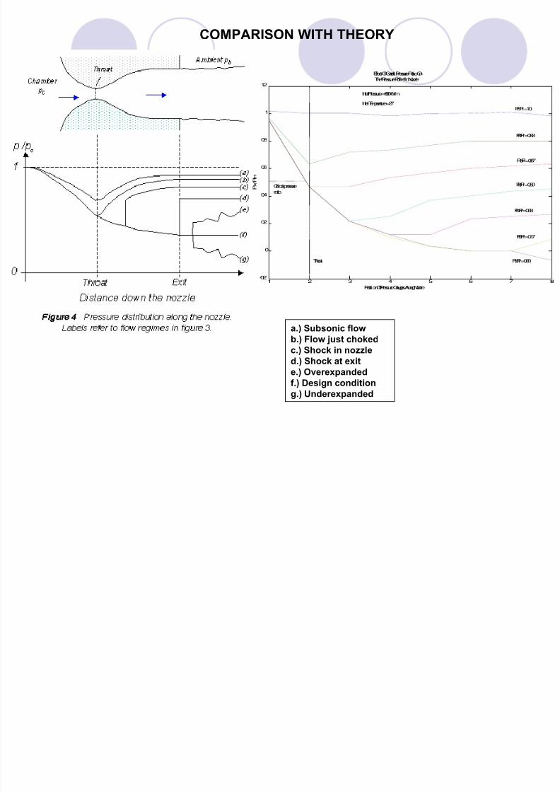
Effect Of Overall Pressure Ratio On
The "Pressure Profile" In Nozzle
Inlet Pressure = 600 kN/m
Inlet Temperature = 27Pb/Pi = 1.0
Pb/Pi = 0.83
Pb/Pi = 0.67
Pb/Pi = 0.50
Pb/Pi = 0.33
Pb/Pi = 0.17
Pb/Pi = 0.00
Critical pressure
ratio
Throat
a.) Subsonic flow
b.) Flow just choked
c.) Shock in nozzle
d.) Shock at exit
e.) Overexpanded
f.) Design condition
g.) Underexpanded
COMPARISON WITH THEORY
8/7/2019 REALprojek-BACK PRESSURE
http://slidepdf.com/reader/full/realprojek-back-pressure 36/36
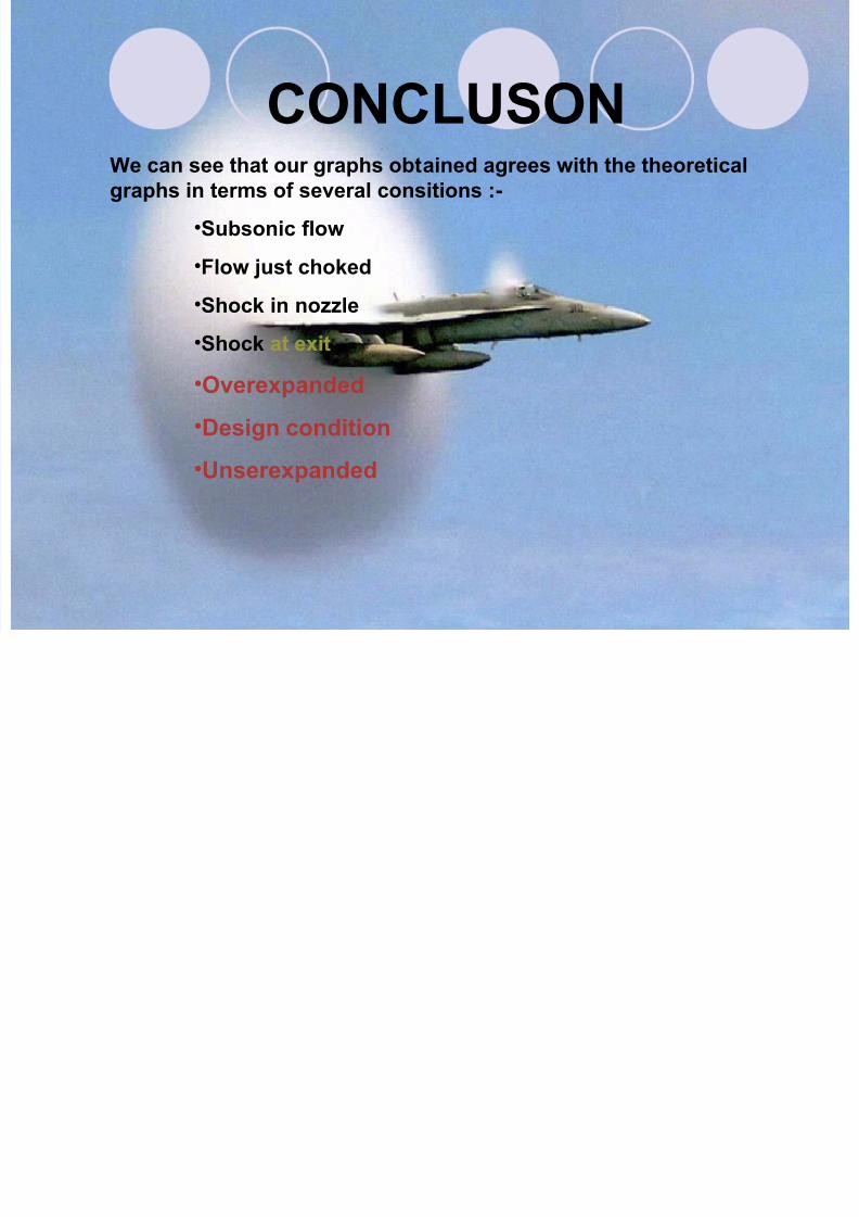
CONCLUSONWe can see that our graphs obtained agrees with the theoretical
graphs in terms of several consitions :-
•Subsonic flow
•Flow just choked
•Shock in nozzle
•Shock at exit
•Overexpanded
•Design condition
•Unserexpanded