A New Structure for Three-phase to Single-phase Ac-Ac Matrix Converters
Vengadeshwaran Velu, Norman Mariun, Mohd Amran, Nashiren Farzilah
Realization of Single Phase to Three Phase Matrix Converterusing SVPWM Algorithm
DOIUDK
10.7305/automatika.2016.07.791621.314.2.025.1.025.3.072:621.376; 512.642
Original scientific paper
The direct AC to AC conversion techniques adopted in the implementation of the single phase to three phaseconverters do not yield the best output results due to the complexity of the segregation process and bidirectionalnature of the input signal. Number of initiatives has been reported adopting a mid DC Link path for creating moreappropriate results. However, none of them provides convincing results in producing the standard three phase outputsignals that are equal in magnitude and 120 degrees away from each other. This paper reports a novel attempt inimplementing the space vector pulse width modulation based Matrix Converter system for direct single phase tothree phase conversion using IGBT based bi-directional switches that produce convincing three phase output signalsfrom a single phase voltage source.
Key words: Matrix Converters, Space Vector Algorithm, Single to Three Phase, Segregation method
Realizacija jednofazno-trofazne matricne transformacije koristeci SVPWM algoritam. Direktna AC/ACpretvorba preuzeta u implementaciji jednofazno-trofaznog konvertera ne daju najbolje rezultate zbog složenostiprocesa segregacije i dvosmjerne prirode ulaznog signala. Mogu se pronaci mnoga rješenja koja koriste središnjiDC link za dobivanje odgovarajucih rezultata. Me�utim, niti jedno od postojecih rješenja ne daje dovoljno do-bar rezultat koji se sastoji od standardne tri faze jednake amplitude koje su me�usobno udaljene 120 stupnjeva. Uovome radu prikazana je nova metoda implementacije modulacije širine vektora temeljena na matricnoj transforma-ciji za jednofazno-trofaznu transformaciju koristeci IGBT dvosmjerne sklopke koje daju zadovoljavajuci trofaznisignal dobiven iz jednofaznog naponskog ulaznog signala.
Kljucne rijeci: matricne transformacije, vektorska modulacija, jednofazno u trofazno, metoda segregacije
1 INTRODUCTION
Conversion of single phase to three-phase is alwaysan interesting task in the direct ac-ac converters sector.Having a converter that is capable of converting a singlephase source voltage into a three phase balanced systemhas numerous advantages such as operating a three phaseinduction motor using a single phase source. Single phaseto three-phase Matrix Converter system adopts the directac-ac conversion technique that converts the single phasealternating source voltage to three phase alternating volt-ages that are equal in magnitude and differ by 120◦ fromeach other. This type of converter has the high potentialof applications where only single phase source is avail-able such as at home, remote town, hill stations, mobilepower source etc. The major difficulty in such convertersis the alternating and bidirectional nature of the input sig-nal. However, advance switching algorithm such as spacevector modulation can be utilized to segregate the inputsignal along with the bidirectional IGBT Switches based
Matrix Converter to produce the required three phase out-put waveforms. Matrix Converter enables the bidirectionalpower flow. Space Vector Pulse Width Modulation is aunique technique that makes the switching complexity ofAC-AC converters much easier. Attempts are being madeto utilize the space vector pulse width modulation tech-niques in the variable frequency drives. Due to this growth,newer topologies are being introduced with superior per-formance characteristics such as minimum harmonic con-tent and unity power factor operation. This paper providesthe details of the implementation of Space Vector PWMmodulation scheme, IGBT based bidirectional switch de-sign and the six switches Matrix Converter system in therealization. This paper also covers the related research ini-tiatives, proposed simulation model and the hardware real-ization model. It also incorporates the results and findingsof the proposed topology.
Online ISSN 1848-3380, Print ISSN 0005-1144ATKAFF 57(1), 129–140(2016)
AUTOMATIKA 57(2016) 1, 129–140 129

Realization of Single Phase to Three Phase Matrix Converter using SVPWM Algorithm V. Velu, N. Mariun, M. Amran, N. Farzilah
2 RELATED RESEARCH INITIATIVES
Many related research initiatives are being carried outby other researchers in the realization of single phase tothree phase conversion. A separation and link approach us-ing sinusoidal PWM modulation scheme has been reported[1]. However high vibration and low voltage transfer ratioissues were reported [1]. Lino.k et al suggested a compen-sation capacitor based Matrix Converter method in whichthe amplitude of the compensated capacitor is utilized toabsorb the single phase power fluctuations. [2].In anotherapproach, a power decoupling capacitor and a LC filter cir-cuit are used to reduce the torque vibration and eliminationof harmonic & pwm ripples respectively. [3]. Anotherresearch suggested using a full bridge rectifier – invertercombo circuits without dc filters are used to produce thethree phase waveforms [4]. Relatively, in another research,an ac reactor with three additional bidirectional switches isused to compensate the fluctuations to obtain the pure sinewave [5].The major issue reported in the earlier researchis the low voltage transfer ratio which can be defined asthe ratio between the output phase voltage and the inputsupply voltage. It is reported that the maximum voltagetransfer ratio achieved is 0.31 using sinusoidal pwm mod-ulation [1]. This research reports a relatively new mod-ulation technique called space vector pwm modulation inview of enhancing the voltage transfer ratio.
3 SINGLE PHASE TO THREE PHASE MATRIXCONVERTER SYSTEM
Matrix Converters are getting popularity in the threephase inverters and direct ac-ac three-phase to three-phaseconverters [6]. Using a single phase source as an inputis a relatively challenging attempt. Fig. 1 shows the blockdiagram of the Single phase to three phase (SP2TP) Matrixconverter system.
Fig. 1. SP2TP Matrix Converter System
The Matrix Converter system consists of six bi-directional switches with reverse blocking capabilities, inwhich two switches are allocated for each phase for for-ward and reverse flow of power. The six bi-directionalswitches are arranged in three limbs each carrying twoswitches as shown in Fig. 2. The midpoints between theswitches in each limb are used as the output terminals ofthe converter. Due to this arrangement, there are eight pos-sible states of Matrix Converters operations such as 100,
101, 110, 010, 011, 001, 000 and 111. Out of the eightavailable states, 000 and 111 are inactive states whereasthe rest of the states are active states. Every half cycle ofthe source voltage is treated as a separate converter andthus the Matrix Converter operates as two equivalent con-verters in contrary series. The operations states have beenobtained for the source positive and negative periods withrational states combinations. SPWM signals were used asthe control signals. The proposed strategy was verifiedwith a three phase balanced resistive load.
Fig. 2. Bidirectional IGBT Switches based Matrix Con-verter
Space Vector Pulse Width Modulation technique uti-lizes the magnitude and phase angle of the resultant vectorof the three phase instantaneous voltages vectors to gener-ate the PWM signals.The derived equivalent vector com-ponent is termed as Space Vector.
The objective of the SVM is to produce voltage andcurrents nearing unity power factor. However, due to anumber of hardware limitations, attaining unity power fac-tor has become more difficult. This paper attempts to de-scribe the most stable and simplest space vector modula-tion technique for the single phase to three phase conver-sion using SP2TP Matrix Converters. The unique contri-bution in this research is to implement the space vectorpwm modulation technique to control the matrix converteroperation.
4 GENERALIZED THEORY OF SPACE VECTORMODULATION
Space Vector Modulation technique adopts the Rotat-ing Magnetic Field theory in which the instantaneous re-sultant flux of the three alternating fluxes that are 120◦
away produces the rotating magnetic field at synchronousspeed.
130 AUTOMATIKA 57(2016) 1, 129–140

Realization of Single Phase to Three Phase Matrix Converter using SVPWM Algorithm V. Velu, N. Mariun, M. Amran, N. Farzilah
Fig. 3. Space Vector Sectors
Similarly, three phase voltages can be represented asa resultant voltage vector VR whose loci of the tip travelin a circle. The circular path can be divided into six sec-tors based on the position of the phase angle variations.At any instant, the resultant voltage VR can be transferredinto α and β components using αβ-transform. The volt-ages V0, V1, V2 . . . ..V7 represents the eight possible statesbetween each sector as shown in Fig. 3.
At any particular moment, the resultant voltage vec-tor VR can be produced by appropriately firing the sec-tor voltages at the given proportional time. SamplingTime TS is the maximum time allocated to complete theswitching of states to produce the equivalent resultant volt-age vector. In Sector-1, the sequence of triggering wouldbe V0V1V2V7V7V2V1V0, however, the sum of the timetaken for this triggering sequence should be equal to thesampling time. The resultant voltage vector can be repre-sented as α β components as shown below:
VR = V∝ + jVβ =2
3
[Va + a.Vb + a2.Vc
], (1)
where a = ej2π3 and a2 = ej
4π3 .
The orthogonal two phase components can be ex-pressed as
V∝ + jVβ =(0.667Va − 0.33 (Vb + Vc))
+ j (0.577 (Vb − Vc))(2)
The tip of the resultant space vector traces in the loci ofa circle. At any instant, the resultant space vector can beequated to the average values of the voltages produced byoperating the converter in the corresponding sector activestates.
At any particular instant, the output phase voltagesof any two windings that are shared carry a voltage of
0.333VS and the other winding carries 0.667VS . In gen-eral, all the active vectors carry a voltage of 0.667VS .
If TS represents the Sampling period, then the averagevalue of the resultant voltage vector can be represented asfollows:
The average voltage of the zero vectors V0 and V7 isZero. Thus the fictitious time of the reference voltage vec-tor can be represented as:
(VRTS) = (VnTn) + (Vn+1Tn+1) (3)
∫ TS2
0
VR dt =
∫ TO2
0
VO dt+
∫ TO2 +Tn
TO2
Vn dt
+
∫ TO2 +Tn+Tn+1
TO2 +Tn
Vn dt+
∫ TS2
TO2 +Tn+Tn+1
V7 dt
The Sampling Time Ts can be written as
TS = 2 (TO + Tn + Tn+1) (4)
By substituting the values of the Vnand V n+1, the ref-erence voltage vector can be obtained in the αβ compo-nents as
∣∣∣∣VV
∣∣∣∣TS2
=2
3VS
[∣∣∣∣∣cos (n−1)
3
sin (n−1)3
∣∣∣∣∣Tn +
∣∣∣∣∣cos (n)
3
sin (n)3
∣∣∣∣∣Tn+1
]
(5)
∣∣∣∣VV
∣∣∣∣TS2
=2
3VS
[cos (n−1)
3cos (n)
3
sin (n−1)3
sin (n)3
] ∣∣∣∣Tn
Tn+1
∣∣∣∣ (6)
The triggering times for the various sectors can be ex-pressed in terms of αβ components as
∣∣∣∣Tn
Tn+1
∣∣∣∣ =√3
2
TSVRMS
[sin (n)
3−cos (n)
3
−sin (n−1)3
cos (n−1)3
].
∣∣∣∣VαVβ
∣∣∣∣(7)
Using the above expression, the triggering time for var-ious sector voltages can be estimated to produce the resul-tant space vector at any particular instant.
5 GENERATION OF THREE PHASE VOLTAGES
One of the possible ways to produce the three phasevoltages that are 120 degrees away from each other froma single phase alternating sourceis to segregate the Sin-gle Phase Input Signal at appropriate angles and share theavailable power across the three phases. Based on the
AUTOMATIKA 57(2016) 1, 129–140 131

Realization of Single Phase to Three Phase Matrix Converter using SVPWM Algorithm V. Velu, N. Mariun, M. Amran, N. Farzilah
Fig. 4. Matlab Simulation of Space Vector PWM of Matrix Converter
Table 1. States of Firing Sequence
Sectors Phase Angle ofInput Signal
State ofFiring Sequences
1 ( 0 – 60) 1012 ( 60 – 120) 1003 ( 120 – 180) 1104 ( 180 – 240) 0105 ( 240 – 300) 0116 ( 300 – 360) 001
Space vector six sectors theory, the desired output can beobtained at any instant by switching the respective sectorvoltages for the pre calculated time. This segregation tech-nique simplifies the firing sequence in such a way that oneof the output phase voltages will be at peak value when theother two phases act as a return path.
Table 1 provides the comparison between sectors pro-portional to states of firing with the range of Phase-A angledistribution.
The αβ component of the resultant voltage vector has afactor of 2/3. This factor limits the maximum possible peakvoltage to 0.667 of the Input Peak Voltage (Vm). Thusthe voltage transfer ratio of the system is 0.667. Further,at the midpoint of each sector of 60 degrees, two of thewaveforms have half of its maximum magnitude and thethird one will be at its peak value in the opposite direction.Thus the available input signal during the 60 degree dura-tion should be utilized for the corresponding state of firingand the other two phases have to be treated as reverse pathwith half of the available magnitude.
In order to segregate the Phase-A waveform, during thefirst 60 degree, the Phase-A shares the input signal withPhase-C and both carry 33.33% of the input magnitude.Phase-B has the Peak amplitude of 66.67% but in the neg-ative direction. The corresponding state to this conditionis 101. During the second 60 degree range, the Phase-Awill carry the available peak amplitude at positive directionwhere Phase-B and Phase-C carries half of the availablemagnitude in reverse direction. The state corresponding tothis condition is 100.
Table 2 shows the specification of the proposed modelof the single phase to three phase matrix converter system.
6 SIMULATION OF MATRIX CONVERTER SYS-TEM
Matlab /Simulink application is used for the simulationof the proposed space vector PWM based single phase tothree phase direct ac-ac Matrix Converter system. The pro-posed simulation circuit can be classified into two sections.The first section is the control system where the SpaceVector Modulation PWM signals are generated taking si-nusoidal fundamental frequency as a reference signal andthe second section of the simulation circuit is the IGBTBidirectional switches based Matrix Converter system fordirect ac-ac conversion.
Figure 4 shows the Space Vector PWM based controlcircuit. It consists of five subsections. The first section isthe Three phase sine wave generator module where the ref-erence three phase voltages that are 120 degrees away fromeach other. The second subsection is the AB Transform
132 AUTOMATIKA 57(2016) 1, 129–140

Realization of Single Phase to Three Phase Matrix Converter using SVPWM Algorithm V. Velu, N. Mariun, M. Amran, N. Farzilah
Table 2. Matrix Converter SpecificationSpecification of the proposed model
Input Source Single Phase, 240V, 50HzOutput Three Phase, (200V-400V), 50 Hz (12.5 Hz to 200 Hz)
Type of Converter Direct AC-AC ConverterAdopted Converter IGBT Based Matrix Converter
Adopted Modulation Scheme Space Vector PWMDesign & Simulation Matlab / Simulink
Inductive Load30-Ph Induction Motor, Squirrel Cage Type, 0.75 kW,
220-240 / 380-415 V, 4 Poles, 1500 rpm, 50 Hz
module where the three phase voltages are transformed totwo phase system based on Clarke Transformation. Thesecond section also produces the sector signals for the sixsectors adopted in the space vector algorithm. The thirdsection is the Ramp Generator module where the high fre-quency carrier signal is produced. It also generates the highfrequency pulse signals at carrier frequency. The fourthsubsection is the Switching Time Calculator module wherethe timing signals are produced based on the sector refer-ence voltages. The fifth module is the Gate Logic moduleswhere the PWM signals are produced based on the switch-ing time signals from the Switching Time Calculator mod-ulator.
Figure 5 shows the simulink model of the Matrix Con-verter Circuit. Matrix converter is designed based on (3x2)switch arrangement with a total of six bidirectional swtich-esthat were used for three limbs of the converter. Eachlimb of the Matrix Converter is designed using two Bidi-rectional switches for the forward and the other one for thereverse power flow.
Table 3 shows the simulation parameters of the pro-posed model of the Matrix Converter system.
Figure 6 shows the bidirectional switch of the MatrixConverter.Each switch is designed using two back to backcommon emitter IGBT modules with parallel diodes andsnubber circuit for reverse voltage blocking. A sinusoidalsingle phase alternating voltage source is used as the powerinput to the converter. The three outputs are taken fromthe midpoints of each limb between the two bidirectionalswitches.
The proposed model was tested under different loadconditions by varying the mechanical torque of the motor.The characteristics of the matrix converter were studiedunder different operating frequencies of the space vectoralgorithm for performance efficiencies.
7 HARDWARE IMPLEMENTATION OF THE MA-TRIX CONVERTER SYSTEM
The proposed space vector PWM based Matrix Con-verter system can be realized practically using the state of
Table 3. Specification of Simulation ModelSimulation Parameters
Modulation Scheme Space Vec-tor PWM
Carrier wave Saw toothCarrier Amplitude (Vcm) 1VCarrier Frequency (fc) 4500 HzCarrier Wave Ratio =(fc) /(fr)
90
Modulation Index = (Vrm)/(Vcm)
1.0
Vref Amplitude(Vrm) Sinusoidal,1V
Vref Frequency (fr) andAngle
50 Hz, zero
3-Ph Ref Amplitude 415 V3-Ph Ref Frequency & an-gle
50 Hz, zero
No. of Samples per cycle 90Sampling Time period (Ts) 222.2 µ sSeconds per Degree 0.617 µ sNo. of degrees per sample 4Sampling time per sector 3.33 ms
AUTOMATIKA 57(2016) 1, 129–140 133

Realization of Single Phase to Three Phase Matrix Converter using SVPWM Algorithm V. Velu, N. Mariun, M. Amran, N. Farzilah
Fig. 5. Matlab Modeling of SP2TP IGBT based Matrix Converter Circuit
Fig. 6. Bidirectional Switch
the art hardware circuitry. Figure 7 provides the block dia-gram representation of the hardware implementation.
Based on the implementation of the space vector al-gorithm in the Matlab/Simulink tool, PWM signal codescan be generated using appropriate application and down-loaded to the Digital Signal Processor (DSP). The digitalsignal processor generates the required PWM signals basedon PWM codes and supplies to the Interface Circuit. TheInterface circuit converts the low voltage PWM signals toan appropriate level that is suitable to drive the IGBT Coredrivers. A separate IGBT core driver/ base board assemblyhas to be designed for individual bidirectional switches ofthe matrix converter.Appropriate gate resistors have to beused based on the selected IGBT characteristics. Six sep-arate IGBT Core drivers are used to control the operationof the six switches of the matrix converter. IGBT Core cir-
Fig. 7. Hardware Implementation of Matrix Converter Sys-tem
cuits provided the necessary PWM pulses to the respectivegate terminals of the bidirectional switches.Six modulesof common emitter dual IGBTbased bidirectional switchesare to be used to construct the Matrix Converters. MatrixConverter hardware can be designed using three legs withtwo bidirectional switches in each leg. It should be notedthat the two switches connected in the same leg should notbe operated at the same time in order to avoid direct shortcircuiting across the input source. The input single phasesource is applied across the legs. The Three phase out-puts are extracted from each leg between the two bidirec-tional switches. A Squirrel cage induction motor is usedas a lagging power factor load. A Synchronization circuitis required in order to synchronize the PWM signals withthe bidirectional sinusoidal input source. Additional cod-
134 AUTOMATIKA 57(2016) 1, 129–140

Realization of Single Phase to Three Phase Matrix Converter using SVPWM Algorithm V. Velu, N. Mariun, M. Amran, N. Farzilah
ing has to be added to the DSP programming to provide thesynchronizing pulse to trigger the closure of the input maincircuit breakers. A miniature circuit breaker can be used asoverload protection device to protect the equipment.
8 RESULTS AND OBSERVATIONS
Figure 8 shows the output line currents of the matrixconverter. The output currents are found to be sinusoidalwith the phase angle difference of 120◦ from each other.The combined waveform resembles the three phase systemand produces three alternating fluxes which in turn pro-duces the rotating magnetic field.
Fig. 8. Output Line Currents under Lagging Power FactorLoad
The induction motor stator windings are connected instar, thus the line currents equals the phase currents of themotor.
Fig. 9. Output Line Voltages under Lagging Power FactorLoad
The line to line output voltages of the Matrix Converterare found to be uniformly alternating with the phase dif-ference of120 degrees from each other. The converter out-put line voltages resembles the three phase system volt-ages, thus the induction motor achieves the required start-ing torque due to relative fluxes in the air gap. Fig.9 aboveshows the line to line output voltages of Matrix Converter.
Fig. 10. RMS Values of Input & Output Currents
Figure 10 shows the rmsvalues of the input and out-put currents.The starting current of the induction motor isfound to be 2% to 3% higher than the normal load cur-rent. But the currents are found to be unbalanced due tothe presence of high harmonic content.
Fig. 11. RMS Values of Input & Output Voltages
Figure 11 shows the rms values of the input and outputvoltages. The difference in magnitude is caused due to thesegregation of the input sinusoidal voltage. Irrespective ofthe inequalities, the performance of the induction motor isfound to be smooth with appropriate slip corresponding tothe applied mechanical load.
AUTOMATIKA 57(2016) 1, 129–140 135
Realization of Single Phase to Three Phase Matrix Converter using SVPWM Algorithm V. Velu, N. Mariun, M. Amran, N. Farzilah
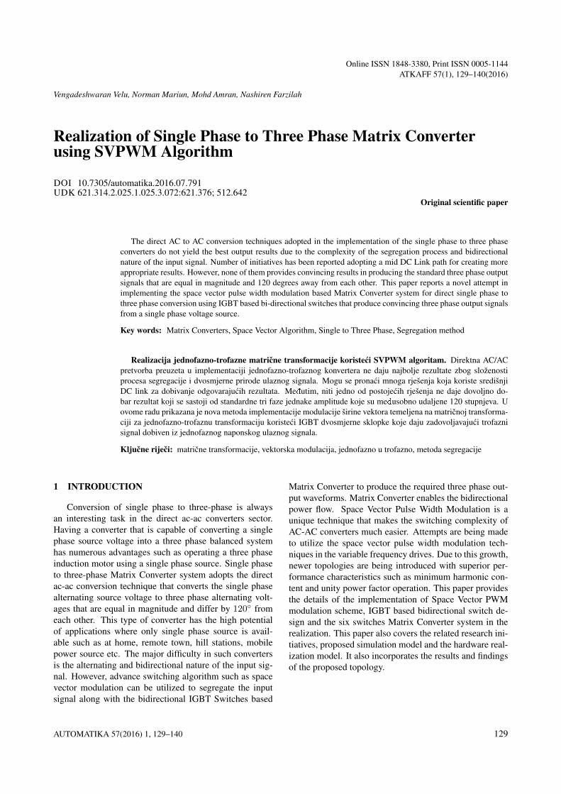
Fig. 12. Speed Characteristics under Induction MotorLoad
Figure 12 shows the speed characteristics of the induc-tion motor. In comparison with the standard speed charac-teristics of the motor, the speed characteristics of MatixConverter operated induction motor resembles closelyto its standard three phase induction motor characteris-tics.howeverit suffers from minute vibrations. The vibra-tion of the motor is caused due to the unbalanced variationin the phase voltages.
Fig. 13. Speed Fluctuation Characteristics
Figure 13 shows the speed fluctuation characteristics ofthe induction motor. The per unit slip fluctuation is foundto be 0.02 of the synchronous speed. This 2% slip fluctua-tion doesn’t have a significant effect in the overall perfor-mance of the induction motor.
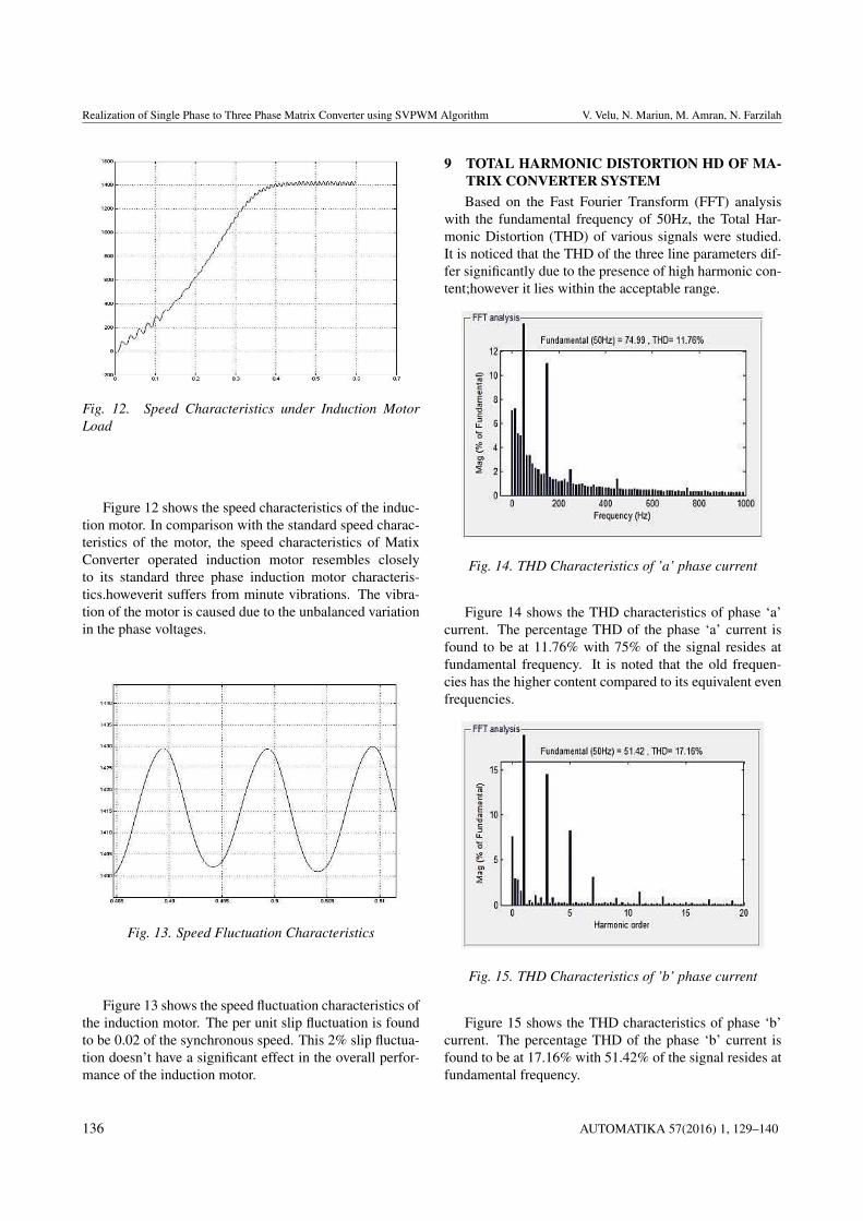
9 TOTAL HARMONIC DISTORTION HD OF MA-TRIX CONVERTER SYSTEMBased on the Fast Fourier Transform (FFT) analysis
with the fundamental frequency of 50Hz, the Total Har-monic Distortion (THD) of various signals were studied.It is noticed that the THD of the three line parameters dif-fer significantly due to the presence of high harmonic con-tent;however it lies within the acceptable range.
Fig. 14. THD Characteristics of ’a’ phase current
Figure 14 shows the THD characteristics of phase ‘a’current. The percentage THD of the phase ‘a’ current isfound to be at 11.76% with 75% of the signal resides atfundamental frequency. It is noted that the old frequen-cies has the higher content compared to its equivalent evenfrequencies.
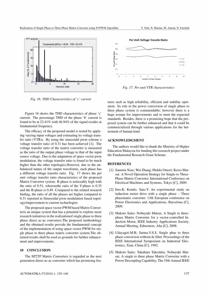
Fig. 15. THD Characteristics of ’b’ phase current
Figure 15 shows the THD characteristics of phase ‘b’current. The percentage THD of the phase ‘b’ current isfound to be at 17.16% with 51.42% of the signal resides atfundamental frequency.
136 AUTOMATIKA 57(2016) 1, 129–140
Realization of Single Phase to Three Phase Matrix Converter using SVPWM Algorithm V. Velu, N. Mariun, M. Amran, N. Farzilah
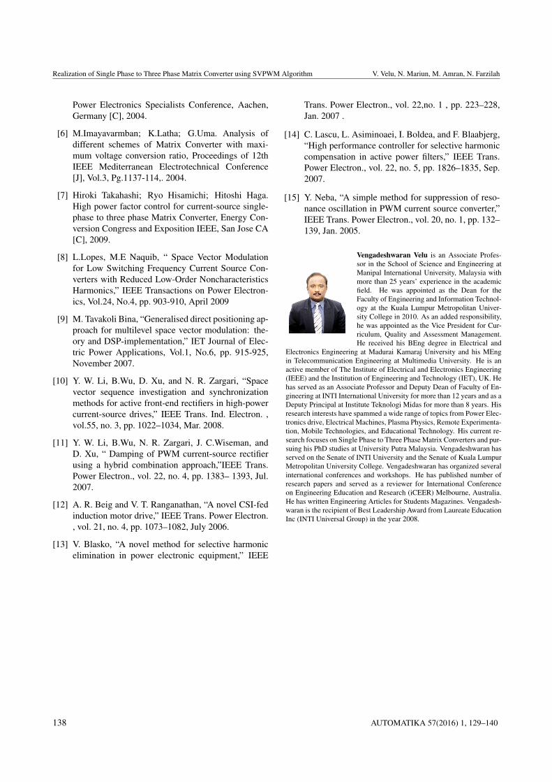
Fig. 16. THD Characteristics of ’c’ current
Figure 16 shows the THD characteristics of phase ‘c’current. The percentage THD of the phase ‘b’ current isfound to be at 23.41% with 46.94% of the signal resides atfundamental frequency.
The efficacy of the proposed model is tested by apply-ing varying input voltages and estimating its voltage trans-fer ratio (VTR)s. By using the sinusoidal pwm scheme avoltage transfer ratio of 0.31 has been achieved [1]. Thevoltage transfer ratio of the matrix converter is measuredas the ratio of the output phase voltage to that of the inputsource voltage. Due to the adaptation of space vector pwmmodulation, the voltage transfer ratio is found to be muchhigher than the other topologies.However, due to the un-balanced nature of the output waveforms, each phase hasa different voltage transfer ratio. Fig. 17 shows the perunit voltage transfer ratio characteristics of the proposedMatrix Converter system. R-phase is noticeably high withthe ratio of 0.51, whereasthe ratio of the Y-phase is 0.35and the B-phase is 0.49. Compared to the related researchfinding, the ratio of all the phases are higher compared to0.31 reported in Sinusoidal pwm modulation based topol-ogy/improvement to current technologies
The proposed space vector PWM based Matrix Conver-teris an unique system that has a potential to explore moreresearch initiatives in the realizationof single phase to threephase direct ac-ac converters.The proposed methodologyand the obtained results provide the fundamental conceptof the implementation of using space vector PWM for sin-gle phase to three phase matrix converter system.The ob-tained results shall be used as grounds for further enhance-ment and improvements.
10 CONCLUSION
The SP2TP Matrix Converters is regarded as the nextgeneration direct ac-ac converter which has promising fea-
Fig. 17. Per unit VTR characteristics
tures such as high reliability, efficient and stability oper-ation. Its role in the power conversion of single phase tothree phase system is commendable; however there is ahuge avenue for improvements and to meet the expectedstandards. Besides, there is a promising hope that the pro-posed system can be further enhanced and that it could becommercialized through various applications for the bet-terment of human kind.
ACKNOWLEDGMENT
The authors would like to thank the Ministry of HigherEducation Malaysia for funding this research project underthe Fundamental Research Grant Scheme.
REFERENCES
[1] Jianmin Xiao; Wei Zhang; Hideki Omori; Keizo Mat-sui. A Novel Operation Strategy for Single-to Three-Phase Matrix Converter, International Conference onElectrical Machines and Systems, Tokyo [C], 2009.
[2] Iino.K; Kondo; Sato.Y. An experimental study oninduction motor drive with a single phase – Threephasematix converter. 13th European conference onPower Electronics and Applications, Barcelona [C],2009.
[3] Makoto Saito; Nobuyuki Matsui. A Single to three-phase Matrix Converter for a vector-controlled In-duction Motor, IEEE Industry Applications Society,Annual Meeting, Edmonton, Alta [C], 2008.
[4] Udayagiri.M.R; Sarma.V.S.S. Single phae to threephase conversion without dc filter. Proceedings of theIEEE International Symposium on Industrial Elec-tronics, Xian, China [C], 1992.
[5] Makoto Saito; Takaharu Takeshita; Nobuyuki Mat-sui. A single to three phase Matrix Converter with aPower Decoupling Capability, The 35th Annual IEEE
AUTOMATIKA 57(2016) 1, 129–140 137
Realization of Single Phase to Three Phase Matrix Converter using SVPWM Algorithm V. Velu, N. Mariun, M. Amran, N. Farzilah
Power Electronics Specialists Conference, Aachen,Germany [C], 2004.
[6] M.Imayavarmban; K.Latha; G.Uma. Analysis ofdifferent schemes of Matrix Converter with maxi-mum voltage conversion ratio, Proceedings of 12thIEEE Mediterranean Electrotechnical Conference[J], Vol.3, Pg.1137-114,. 2004.
[7] Hiroki Takahashi; Ryo Hisamichi; Hitoshi Haga.High power factor control for current-source single-phase to three phase Matrix Converter, Energy Con-version Congress and Exposition IEEE, San Jose CA[C], 2009.
[8] L.Lopes, M.E Naquib, “ Space Vector Modulationfor Low Switching Frequency Current Source Con-verters with Reduced Low-Order NoncharacteristicsHarmonics,” IEEE Transactions on Power Electron-ics, Vol.24, No.4, pp. 903-910, April 2009
[9] M. Tavakoli Bina, “Generalised direct positioning ap-proach for multilevel space vector modulation: the-ory and DSP-implementation,” IET Journal of Elec-tric Power Applications, Vol.1, No.6, pp. 915-925,November 2007.
[10] Y. W. Li, B.Wu, D. Xu, and N. R. Zargari, “Spacevector sequence investigation and synchronizationmethods for active front-end rectifiers in high-powercurrent-source drives,” IEEE Trans. Ind. Electron. ,vol.55, no. 3, pp. 1022–1034, Mar. 2008.
[11] Y. W. Li, B.Wu, N. R. Zargari, J. C.Wiseman, andD. Xu, “ Damping of PWM current-source rectifierusing a hybrid combination approach,”IEEE Trans.Power Electron., vol. 22, no. 4, pp. 1383– 1393, Jul.2007.
[12] A. R. Beig and V. T. Ranganathan, “A novel CSI-fedinduction motor drive,” IEEE Trans. Power Electron., vol. 21, no. 4, pp. 1073–1082, July 2006.
[13] V. Blasko, “A novel method for selective harmonicelimination in power electronic equipment,” IEEE
Trans. Power Electron., vol. 22,no. 1 , pp. 223–228,Jan. 2007 .
[14] C. Lascu, L. Asiminoaei, I. Boldea, and F. Blaabjerg,“High performance controller for selective harmoniccompensation in active power filters,” IEEE Trans.Power Electron., vol. 22, no. 5, pp. 1826–1835, Sep.2007.
[15] Y. Neba, “A simple method for suppression of reso-nance oscillation in PWM current source converter,”IEEE Trans. Power Electron., vol. 20, no. 1, pp. 132–139, Jan. 2005.
Vengadeshwaran Velu is an Associate Profes-sor in the School of Science and Engineering atManipal International University, Malaysia withmore than 25 years’ experience in the academicfield. He was appointed as the Dean for theFaculty of Engineering and Information Technol-ogy at the Kuala Lumpur Metropolitan Univer-sity College in 2010. As an added responsibility,he was appointed as the Vice President for Cur-riculum, Quality and Assessment Management.He received his BEng degree in Electrical and
Electronics Engineering at Madurai Kamaraj University and his MEngin Telecommunication Engineering at Multimedia University. He is anactive member of The Institute of Electrical and Electronics Engineering(IEEE) and the Institution of Engineering and Technology (IET), UK. Hehas served as an Associate Professor and Deputy Dean of Faculty of En-gineering at INTI International University for more than 12 years and as aDeputy Principal at Institute Teknologi Midas for more than 8 years. Hisresearch interests have spammed a wide range of topics from Power Elec-tronics drive, Electrical Machines, Plasma Physics, Remote Experimenta-tion, Mobile Technologies, and Educational Technology. His current re-search focuses on Single Phase to Three Phase Matrix Converters and pur-suing his PhD studies at University Putra Malaysia. Vengadeshwaran hasserved on the Senate of INTI University and the Senate of Kuala LumpurMetropolitan University College. Vengadeshwaran has organized severalinternational conferences and workshops. He has published number ofresearch papers and served as a reviewer for International Conferenceon Engineering Education and Research (iCEER) Melbourne, Australia.He has written Engineering Articles for Students Magazines. Vengadesh-waran is the recipient of Best Leadership Award from Laureate EducationInc (INTI Universal Group) in the year 2008.
138 AUTOMATIKA 57(2016) 1, 129–140

Realization of Single Phase to Three Phase Matrix Converter using SVPWM Algorithm V. Velu, N. Mariun, M. Amran, N. Farzilah
Norman Bin Mariun is a Professor and wasthe Head Department of Electrical and Elec-tronic Engineering (2001-2004), Deputy Deanof Research and Post Graduate Studies forthe Faculty of Engineering, UPM (2004-2009),Deputy Director of Research Management Cen-ter, UPM(2009-2010) and the Director of Re-search Management Center, UPM (2010-2012).As a director of RMC, UPM he was responsiblefor the management and allocation of the RM80million Research University Budget allocated an-
nually to UPM. He was also a Senate member of UPM. Now he is headingCAPER (Centre for Advance Power and Energy Research) at UPM. Grad-uated from University of Nottingham in Electrical and Electronic Engi-neering (1980). He obtained MSc in Electrical Engineering from NorthCarolina State University, USA (1983) and PhD from University of Brad-ford, United Kingdom (1998). His area of research interest is ElectricalPower Engineering including Energy Efficiency and Renewable Energy,and Power Electronics application in power system and drives.He hasmore than 30 years of experience in teaching electrical and electronicsengineering courses, developing electrical engineering laboratory, devel-oping curriculum for Electrical and Electronic Engineering Program forBachelor and Post-Graduate level, and supervision of more than 80 un-dergraduates and more than 70 post graduates students (8 PhD and 32Master students completed as main supervisor). Currently he is super-vising as main supervisor 9 PhD students and 1 Master student. He hasalso served as external examiners for MSc and PhD candidates for UM,UKM, USM, UTM, UNITEN, University of Nottingham, and ANNAUniversity India, a total of more than 40 students.He has authored andco-authored more than 250 (>90 in journals, >90 in international pro-ceedings, >40 in national proceedings, 30 seminar/workshop) academicand professional papers and reports. He has carried out various consultingprojects (20) while attached with engineering consultant firms (J&A As-sociates, Hashim& NEH, and UKM Perunding).He has wide experiencesin administrative duties that include Director of RMC, UPM, Deputy Di-rector Research Fund, Deputy Dean of Research, Head of Department,Head of Curriculum Development, Head of MSc. Electrical Engineeringprogram, Head of Intensive Research Priority Areas Research Groups,Chairman of Panel Member of Intensive Research Priority Areas (Manu-facturing), Chair for Evaluation Panel for MOSTE-IGS and MOSTI Tech-nofund projects, and others. Appointed as National Accreditation Boardand Board of Engineers Malaysia Panel Member for Engineering Accred-itation Council for assessing B.Eng. Electrical and Electronic Engineer-ing Programs at various universities and institutions of higher learningand appointed as panel of energy expert/specialist by MalaysianEnergy-Center. Have also served as External Assessor and Examiner for Bache-lor of Electrical Engineering program, UTM (Jan 2000- Dec 2001) and asExternal Examiner for UCSI (2007-2009) and recently appointed as ex-ternal examiner and assessor for UNISEL and KLMU.He is a RegisteredProfessional engineer with the Board of Engineers Malaysia and an Inter-viewer for BEM Professional Interview. He is aFellow of IEM (Institutionof Engineers Malaysia), Member of Board of Examiners, IEM.He hasalso served as a Committee Member of Engineering Education TechnicalDivision and Electrical Engineering Technical Division IEM. He was alsoa CIRED Committee Member for 2000-2005.With Institute of Electricaland Electronics Engineers (USA), IEEE currently he is a Senior Mem-ber and globally IEEE PES Section-Chapter Committee Chair. He wasthe IEEE MGA Admission and Advancement Committee Member (2011)and IEEE PES Section-Chapter Relation Officer (2010-2014). He is thePast Chair of Malaysia Section (2005-2007); Past Secretary (2002) andVice-Chair (2003-2004); and Past-Chair of IEEE Power Engineering So-ciety Malaysia Chapter (2000-2003). He has also served IEEE at globallevel as IEEE MGA Geographic Unit Support Committee (2010), andAsia Pacific Region IEEE Executive Committee member(2007-2010).Hehas also been awarded the ITEX 2005 Silver Medal and Bronze Medal,ITEX 2006 Gold Medal, ITEX 2008 Malaysia Innovative Product Award,and the British Invention Show 2005 Gold Medal, Eureka Brussels 2006Gold Medal, INPEX 2007 USA Gold Medal IENA 2008 Germany GoldMedal and INNOVA 2009 Belgium Special Award and Gold Medal forhis research work.
Mohd Amran Mohd Radzi was born in KualaLumpur, Malaysia, in 1978. He received hisB.Eng. (Hons.) and his M.Sc. degrees fromUniversiti Putra Malaysia (UPM), Serdang, Se-langor, Malaysia, and his PhD degree in 2010from University of Malaya. He is currentlyAssociate Professor at Department of Electri-cal and Electronic Engineering, Faculty of Engi-neering, UPM and Researcher at Centre for Ad-vanced Power and Energy Research (CAPER),UPM. His research interests are power electron-
ics, power quality, and renewable energy.Dr. Radzi is a Member of theInstitution of Engineering and Technology (IET), U.K., and a CharteredEngineer. He is also a Member of the Institute of Electrical and Electron-ics Engineers (IEEE), USA.
Nashiren F. Mailah graduated with B.Eng(Hons.) degree in Electrical and Electron-ics Engineering from University of Hudders-field, United Kingdom in 1999 and obtainedher M.Eng from UniversitiTeknologi Malaysia,Malaysia in 2001. She received her Ph.D in Elec-trical Power Engineering from Universiti PutraMalaysia, Malaysia in 2010. Her area of researchinterests are power electronics converters and itsapplications in power systems and industry. She
has been with Department of Electrical and Electronic Engineering, Uni-versiti Putra Malaysia, Malaysia since 2001 as a lecturer and currently, aSenior Lecturer.
AUTOMATIKA 57(2016) 1, 129–140 139

Realization of Single Phase to Three Phase Matrix Converter using SVPWM Algorithm V. Velu, N. Mariun, M. Amran, N. Farzilah
AUTHORS’ ADDRESSESAssoc. Prof. Vengadeshwaran Velu,Electrical and Electronics Engineering,School of Science and Engineering (SoSE),Manipal International University,No 1, MIU Boulevard, 71800,Putra Nilai, Negeri Sembilan Darul Khusus, Malaysia,email: [email protected]. Norman Bin Mariun, Ph.D.PEng. FIEM, SMIEEE (USA)Department of Electrical and Electronic Engineering,Faculty of Engineering, Universiti Putra Malaysia,43400 Serdang Selangor, MALAYSIA,e-mail: [email protected]. Prof. Mohd Amran Mohd Radzi, Ph.D.Department of Electrical and Electronic Engineering,Faculty of Engineering,Universiti Putra Malaysia (UPM),43400 UPM Serdang,Selangor Darul Ehsan, MALAYSIA,email: [email protected] Farzilah Binti Mailah, Ph.D.Department of Electrical and Electronic Engineering,Faculty of Engineering,Universiti Putra Malaysia (UPM),43400 UPM Serdang,Selangor Darul Ehsan, MALAYSIA,email: [email protected]
Received: 2014-03-05Accepted: 2015-08-20
140 AUTOMATIKA 57(2016) 1, 129–140