REALISTIC FUN SCALE MODEL - Hobbicomanuals.hobbico.com/dyf/dyf-pt19-manual.pdf• REALISTIC FUN...
32
TM PT-19 • BUILDS QUICKLY • REALISTIC FUN SCALE MODEL • HUGE, 89" WINGSPAN (IMAA Legal) READ THROUGH THIS INSTRUCTION MANUAL FIRST. IT CONTAINS IMPORTANT INSTRUCTIONS AND WARNINGS CONCERNING THE ASSEMBLY AND USE OF THIS MODEL WARRANTY Dynaflite guarantees this kit to be free from defects in both material and workmanship at the date of purchase. This warranty does not cover any component parts damaged by use or modification. In no case shall Dynaflite's liability exceed the original cost of the purchased kit. Further, Dynaflite reserves the right to change or modify this warranty without notice. In that Dynaflite has no control over the final assembly or material used for final assembly, no liability shall be assumed nor accepted for any damage resulting from the use by the user of the final user-assembled product. By the act of using the user-assembled product, the user accepts all resulting liability. If the buyer is not prepared to accept the liability associated with the use of this product, return this kit immediately in new and unused condition to the place of purchase. ©Copyright 1997 PT19P03 Printed in USA
Transcript of REALISTIC FUN SCALE MODEL - Hobbicomanuals.hobbico.com/dyf/dyf-pt19-manual.pdf• REALISTIC FUN...

TM
PT-19• BUILDS QUICKLY
• REALISTIC FUN SCALE MODEL• HUGE, 89" WINGSPAN (IMAA Legal)
READ THROUGH THIS INSTRUCTION MANUAL FIRST. IT CONTAINSIMPORTANT INSTRUCTIONS AND WARNINGS CONCERNING THE ASSEMBLYAND USE OF THIS MODEL
WARRANTYDynaflite guarantees this kit to be free from defects in both material and workmanship at the date ofpurchase. This warranty does not cover any component parts damaged by use or modification. In nocase shall Dynaflite's liability exceed the original cost of the purchased kit. Further, Dynaflite reservesthe right to change or modify this warranty without notice. In that Dynaflite has no control over thefinal assembly or material used for final assembly, no liability shall be assumed nor accepted for anydamage resulting from the use by the user of the final user-assembled product. By the act of usingthe user-assembled product, the user accepts all resulting liability. If the buyer is not prepared toaccept the liability associated with the use of this product, return this kit immediately in new andunused condition to the place of purchase.
©Copyright 1997 PT19P03 Printed in USA

Introduction ......................................................2Precautions.......................................................3Preparations.....................................................3
Required Accessories .......................................3Suggested Supplies .........................................3Optional Accessories .......................................4Building Notes.................................................4Adhesives .......................................................4Common Abbreviations....................................5Types of Wood ................................................5Metric Conversion............................................5Die Patterns ................................................6&7
Build the Fuselage ...............................................8Build the Wing .....................................................12Build theAilerons ...........................................................16Build the Stabilizer & Elevators ...........................17Build the Vertical Fin & Rudder .........................19Mount the Wing to the Fuselage .........................20FinalAssembly .................................................22Finishing..........................................................26Set The Control Throws...................................27Balance Your Model.......................................27
Preflight..................................................27At Home...............................................................27At the Flying Site ...........................................28
Engine Safety Precautions................................28FLYING.............................................................28
Find a Safe Place to Fly..................................28Takeoff..........................................................29Flight.........................................................29Landing ........................................................29Terms & Definitions ........................................30
Cockpit & Wing Tip Patterns...........Center Spread
Congratulations on your choice of this kit for yournext project. The Fairchild PT-19 is a Fun Scale®model of a true classic aircraft and has the presencethat only a big model can carry off.
At Dynaflite we take pride in offering kits that aresimple and straight forward to build and providevalue for your modeling dollar. Because of the sizeand cost of this model we assume you have builtseveral models and have a general workingknowledge of modeling and its terms. If you HAVENOT built and flown several kits, do yourself a favorand get some experience before beginning this kit.
Your PT-19 is not a toy, but a sophisticated workingmodel that functions like a full-size airplane. Becauseof its performance, if you do not assemble andoperate the PT-19 correctly, you could possibly injureyourself or spectators and damage property.To make your R/C modeling experience totallyenjoyable, we recommend that you get assistancewith assembly and your first flights from anexperienced, knowledgeable modeler. You'll learnfaster and avoid risk to your model before you'retruly ready to solo. Your local hobby shop hasinformation about flying clubs in your area whosemembership includes qualified instructors.
You can also contact the national Academy of ModelAeronautics (AMA), which has more than 2,300chartered clubs across the country. We recommendyou join the AMA which will provide you withinsurance coverage at AMA club sites and events.AMA Membership is required at chartered clubfields where qualified flight instructors are available.Contact the AMA at the address or toll-free phonenumber below.
Academy of Model Aeronautics5151 East Memorial Drive
Muncie, IN 47302(800) 435-9262
Fax (765) 741-00572

1. You must assemble the plane according to theinstructions. Do not alter or modify the model, asdoing so may result in an unsafe or unflyable model.In a few cases the instructions may differ slightlyfrom the photos or plan. In those instances thewritten instructions should be accepted as correct.
2. You must take time to build straight, true and strong.
These are the items "not included" with your kit, thatyou will need to purchase separately. Items inparentheses (GPMQ3141) are suggested partnumbers recognized by distributors and hobbyshops and are listed for your ordering convenience.GPM is the Great Planes® brand, TOP is the TopFlite® brand and HCA is the Hobbico® brand.
3. You must install all R/C and other components sothat the model operates properly on the ground andin the air.
4. You must test the operation of the model before thefirst and each successive flight to insure that allequipment operates correctly. You must also makecertain that the model has remained structurally sound.
NOTE: We, as the kit manufacturer, can provideyou with a quality kit and great instructions, butultimately the quality and flyability of your finishedmodel depends on how you assemble it; therefore,we cannot in any way guarantee the performanceof your completed model and no representationsare expressed or implied as to the performance orsafety of your completed model.
4 channel radio with 3 standard, 2 high torqueand one quarter scale servo.Engine - 1.08 to 1.5 2-stroke or 1.2 to 1.64-strokeEngine mount and mounting hardware16oz.Fueltank(GPMQ4107)Standard fuel tubing (GPMQ4131)(2) 5" to 6" main wheels(1) 1-1/2" tail wheel (GPMQ4243)(4) 1/4" Wheel collars (DUBQ1200)(2) 1/8" Wheel collars (GPMQ4304)Top Flite® MonoKote® covering film (4 rolls)or Coverite™ 21 st Century® FabricPaint for fuelproofing, the engine cowl andthe windshields(1)OR(2) 1/3 Scale pilot(s)1/4" Latex Foam Rubber (HCAQ1000)
These are the adhesives and supplies that you willneed to build your Pt-19. We recommend GreatPlanes Pro™ CA and Epoxy
Please inventory and inspect all parts carefullybefore starting to build! If any parts are missing,broken or defective or if you have any questionsabout building or flying this model, please call us at(217) 398-8970 and we'll be glad to help. If you arecalling for replacement parts, please look up thepart numbers and have them ready when calling.
4 oz. Thin CA Adhesive - (GPMR6004)2 oz. Thick CA Adhesive - (GPMR6015)CA Accelerator - (HCAR3750)CA Applicator Tips - (HCAR3780)6-Minute Epoxy - (GPMR6045)30-Minute Epoxy - (GPMR6047)4 oz. Aliphatic Resin Glue (GPMR6161)
3

A flat, durable, easy-to-handle sanding tool is anecessity for building model airplanes. Great Planesmakes a complete range of Easy-Touch'" Bar Sandersand replaceable Easy-Touch adhesive-backedsandpaper. On our workbench, we have four 11"Easy-Touch Bar Sanders, equipped with #50, #80,#150 and #220-grit sandpaper. This setup is all that isrequired for almost any sanding task. Custom sandingblocks can be made from balsa for sanding hard-to-reach spots. We also keep some #320-grit wet-or-drysandpaper for finish sanding before covering.
For future reference, here's a list of Easy-Touch BarSanders and adhesive-backed sandpaper:
5-1/2" Bar Sander (GPMR6169)11 "Bar Sander (GPMR6170)22" Bar Sander (GPMR6172)
12' Roll of adhesive-backed sandpaper,80-grit (GPMR6180)
150-grit (GPMR6183)220-grit (GPMR6185)
Assortment pack of 5-1/2" strips (GPMR6189)
IMPORTANT: During construction you will be using anumber of balsa sticks to frame various assemblies.Ample material is included but you should study theplans, then make an effort to cut the longest piecesyou will need first. Label the pieces as you cut themfor later reference. By doing this now, you won'thave to splice pieces together later.
This kit is built with three types of glue.
Cyanoacrylate: CA glues cure almost instantaneouslyand are moderately strong. There are differentviscosities of CA's intended for different conditionsyou will encounter when you build. Thin CA is greatfor "tack-gluing," for glue joints that fit well and forparts that are already joined but need to bepermanently bonded. Medium CA is used for generalconstruction where you apply glue to one part, thenjoin it to another part. Thick CA is great for glue jointsthat don't fit perfectly or parts that require a little timefor positioning before the glue cures. You willencounter many other conditions that require one orthe other types of CA.
Robart Oleo landing gear struts (ROBQ1600)
Midwest scale instrument panel (MIDQ1105)
Always use CA in a well ventilated area. Open somewindows or place a fan in the room to circulate theair. Do not lean directly over your work when youuse CA and look away while it cures or "sets off."CA can cure immediately upon contact with skin soif you accidentally bond your fingers, do not usevigorous motion to separate them. Use CA Debonder(GPMR6039) or acetone (nail polish remover) orsoak your fingers in warm water for a few minutes.
4

Never point the tip of a CA bottle toward your faceand be especially careful when you unclog a CA tip.Hobbico CA Applicator Tips (HCAR3780) are highlyrecommended and will help keep the bottle fromclogging. Keep paper towels or tissues close by toimmediately absorb excess CA dropped on yourmodel or work area. Read all the warning labels onyour CA bottle. CA Accelerator is a chemical thatyou can spray over uncured CA to make it cureimmediately. A mist spray of accelerator will do thejob. Do not inhale the vapors! Some modelers"preprime" the parts to be glued with accelerator,join them, then add the CA. This way the CA isguaranteed to cure immediately. This prepriming isespecially handy when you use thin CA because itwill cure before all of the glue soaks into the woodaway from the glue joint. We do not recommendyou build your entire model with this method anduse accelerator only when necessary. Often,overspray from accelerator used hours or even daysearlier on nearby glue joints will cause the CA youuse on the next step to cure prematurely andunexpectedly - so be careful!
Aliphatic Resin - Resin glues require that parts bepinned or clamped together while the glue dries/-typically 1 5 - 3 0 minutes. Resin glues are verystrong and work well with balsa and plywoods.
Epoxy - Epoxy glues are the strongest but require themost time to cure. Six-minute epoxy cures the fastest;it sets within six minutes but is not fully cured for onehour or more. Thirty-minute epoxy is the strongest asit allows the epoxy to soak into the wood thoroughly.While it sets within 30 minutes, it will not be fullycured for two or more hours.
Inch Scale
Fuse = FuselagePly = Plywood
" = Inches
Stab = Horizontal StabilizerLE = Leading edge (front)TE = Trailing edge (rear)
Balsa Basswood Plywood
Metric Scale
5

DIE PATTERNS
6

DIE PATTERNS
7

1. Place the fuselage drawing on your workbenchand cover it with wax paper from bulkhead D aft. Beginconstruction by building the right rear side structure.
2. Using two 1 /4" x 15/16" x 42" balsa sticks,cut and fit the rear side stringers. Cut the longestpieces first. Pin and glue the parts into position.
3. Cut the diagonals from a 1/4" x 1/2" x 30"balsa stick and glue into position.
6. Place the right fuselage side over the plansand mark the locations of bulkheads B, C, D, E, F,and G on the side. Place the left side over the rightand transfer the marks to the left side. Next, markeach former at the center of the bottom edge. Placethe fuselage plan on your building board and drawa line down the length of the plans along thefuselage center with a long straightedge. Thesemarks and lines will be used to align the fuselage inthe following steps.
7. Glue bulkheads D and E to the right fuselageside using 6-minute epoxy. Be sure the bulkheadsare at a 90 degree angle to the side. Epoxy willproduce the strongest joint but you can use thin CAwith accelerator if you are in a hurry.
4. Fit the ply fuselage front to the fuse rear. Cutdoublers for the two joints from a 1 /8" x 1 /4" x 30"balsa stick. When satisfied with the fit, glue them with6-minute epoxy.
5. The left fuselage side is built over the rightside. Remove the right side from your building boardand turn it over. Use the leftover 1 /8" x 1 /4" stick toshim the forward ply side. Cover the side with waxpaper. Follow steps 2, 3 and 4 to build the left side,aligning the parts over the right side.
8. Glue the left fuselage side to bulkheads D and Eusing 6-minute epoxy. Align the side with the marks
8

you made earlier. Before the glue cures, sight acrossthe top of both sides to double check the alignment.
9. Slip bulkhead B over the outside of thefuselage. Do NOT glue until the next step.
12. Glue bulkhead C to the fuselage sides with6-minute epoxy. The bulkhead is slightly large so asnot to bind on the sides. Use leftover 1/8" x 1/4"balsa sticks to reinforce the bulkhead/fuselage jointas shown in the photo. The 1/8" x 1/4" stick abovethe lower deck is glued to the front of the bulkhead.The stick below the lower deck is glued to the aft sideof the bulkhead and INSIDE the fuselage.
13. Build bulkheads F and G over the fuselagedrawing using leftover 1/4" x 1/2" balsa sticks.
14. Pull the tail together and hold it in positionwith clothespins. Do NOT glue until later.
10. Glue the top and bottom deck into positionwith 30-minute epoxy. Also glue bulkhead B to thefuselage sides and both decks with 30-minute epoxy.Each deck spans from the firewall back to bulkheadD. The rear of the lower deck is installed 9/16" upfrom the bottom of bulkhead D. Use masking tape asneeded to hold the assembly together while the epoxycures. 30-minute epoxy is used to give enough time toposition the parts and also for strength.
11. Glue the doubler to bulkhead C using thebottom curves to align the doubter.
Use this photo for the next four steps.15. Lightly sand the sides of bulkheads F and G
to match the taper of the sides. Install them in thesides and hold them in position with pins. Do NOTglue until later.
16. Place the fuselage upright over the fuselagedrawing. Align the center mark on each bulkheadwith the line you drew down the plan earlier. Youwill need to sight down from above the fuselage as itwill not rest flat on the drawing. Adjust the tail, as
9

needed, to get the center of each bulkhead to alignproperly. When you are satisfied that everything isaligned properly, glue the tail together. Also gluebulkhead F and G to the fuselage sides.
17. Glue the top ply part of bulkheads F and Ginto position. Note that the top part of F goes in frontof the lower part of F. The rear of the top part of Ggoes 1/2" in front of the lower part of G.
18. Cut three 1 /4" x 1 /2" x 24" balsa sticks to alength of 19". Glue these top rear stringers tobulkheads E, F and G.
21. Use leftover 1/4" x 1/2" balsa sticks toframe between the bottom stringers at bulkhead E.Just tack glue them into position at this time as youmay need to adjust them when the wing is fitted.
19. Notch the bottom stringers to accept the die-cut 1/8" ply tailwheel plate. The correct position forthe bracket will allow the 1/4" x 1/2" stringers,added in the next step, to extend 1 /4" below thebottom of the 1/4" x 15/16" side stringers. Whensatisfied with the fit glue the die-cut plate intoposition with 6-minute epoxy.
20. Cut two 1/4" x 1/2" x 30" balsa sticks to alength of 28-1/2". Fit and glue these bottomstringers into position. You will need to notch them atbulkheads F and G. They should extend 1 /4" belowthe 1/4" x 15/16" side stringers. You can let themextend into the area where the tailwheel plate ismounted if desired.
22. Glue the 1 /4" ply wing hold down plate intoplace with 6-minute epoxy. Use some leftover1/4" x 3/8" basswood sticks to reinforce above theply plate.
23. Roll the fuselage over and glue BulkheadsB-1 and D-1 into place. Bulkhead B-1 is glued3-1/16" behind Bulkhead B and bulkhead D-1glued 2" behind bulkhead D.
is
24. Cut and glue the stringers between bulkheadsB and B-1 and between bulkheads D and D-1. Useleftover 1/4" x 1/2" balsa sticks.
10

25. Use 1/8" x 3" x 24" balsa to sheet betweenbulkheads B and C, from the top deck down. Soakthe outside of the sheeting with water as needed toget it to bend around the curves. Thin CA works wellon damp balsa.
26. Use a leftover piece of 1/8" x 1/4" balsastick to make a filler wedge between bulkheads Cand D. Blend the stick from C to D. This creates aledge, to which the top sheeting is glued.
cutting the sheeting to length as the leftover will beused in the next step. You will have to soak thesheeting with water to get it to bend properly. Asmall amount of ammonia or 50% alcohol added tothe water will help to soften the wood fibers. Bepatient, the best time to do the bending is when thebalsa starts to dry to a damp state. After the sidesheeting strips are glued into position, cut a roughcockpit opening as shown in the photo. This openingwill relieve some of the stress in the sheeting andallow it to dry in the proper shape. There is apattern for the exact opening in the center of thismanual. Do not glue the center strip until step 29.
—I 28. Sheet between bulkheads D and E using theleftover 1/8" x 3" balsa sheeting from above, just asyou did in the previous step.
29. Fit and glue the center strip of sheeting.
27. Caution - carefully read and understand thisentire step before proceeding! Use 1/8" x 3" x 24"balsa to sheet the fuselage top from bulkhead B to .This will be done with three strips. Be careful when
30. Use 1/8" x 3" x 24" balsa to sheet frombulkhead E to G. This is a compound curve so goslowly and be patient. It won't be as hard as itseems. Just be sure the balsa sheeting is well soaked.
11

31. Glue the 1/4" x 1/2" x 42" balsa stringersto the fuselage sides.
Set the fuselage aside until later. It will be completedafter the wing and stabilizer are built.
If you have not done so already, now is a good timeto obtain a mount for your engine. If you will beusing a two or four stroke engine a Great Planes60-120 mount (GPMG1091) will work well. If youwill be using a chainsaw type engine you willprobably need a spacer behind the mount.
3. Pin the 1 /4" x 3/8" x 42" basswood lowerspar over the plan.
4. Pin the 3/8" x 1/2" x 42" balsa stick onthe dashed lines called "shim stick." This will holdthe rear of the ribs at the proper angle until there areenough pieces to hold the wing rigid.
5. Punch the ribs from their die-cut sheets,sanding the backs lightly if they do not come outeasily. Number each rib as you do so; don't forget tonumber the aileron ribs as well. Check the fit of thespar to the spar notches in each rib.
1. Lay the RIGHT WING PLAN on yourbuilding board and cover it with wax paper.
2. Prepare a leading edge skin. Locate onepiece of 3/32" x 3" x 42" balsa sheet and one pieceof 3/32" x 3" x 36" balsa sheet. Join them togetherso that the ends are even with each other on one side.Form a skin using your favorite method (we usemasking tape to form a hinge and then join them withaliphatic resin glue). Sand the best side smooth with150-grit sandpaper. Position the skin on the planaligning the aft edge with the center of the spar. Markthe front of the leading edge on the skin at the root rib(W1) and the tip rib (W11). Use a long straightedgeto trim the excess sheeting from the skin. Leave 1/4"extra to allow for the curvature of the ribs. Set this skinaside for use later. Save the piece that was trimmedoff for the other wing panel and use it in place of thesecond 3/32" x 3" x 26" sheet.
6. Glue the 1/8" die-cut ply landing geardoublers to ribs W2, W3 and W4 using 30-minuteepoxy. Glue them to the sides shown on the plans.There are two doublers for W2. The one with thelong cutout is glued to the side facing the wing tip.This cutout will lock in the landing gear stub (torque)block. Check the fit of the landing gear block andstub block in their cutouts.
12

11. Glue the 1 /4" x 3/4" x 42" balsa leadingedge stick to the front of the ribs. Align the top of the
7. Glue ribs W2-W11 into place on the lowerspar with a drop of CA. Pin the rear of each rib tothe shim stick.
8. Use the dihedral gauge to obtain theproper angle (6 degrees) of W1. Glue W1 intoplace on the lower spar. Pin the rear of W1 to theshim stock. Use a long straightedge to insure thatW1 is flat.
9. Glue the 1 /4" x 3/8" x 42" basswood topspar to the ribs.
10. Cut a 3/8" x 3/4" x 24" balsa stick to thecorrect length and glue it to the rear of W7-W10.The ends are glued to W6 and W11. Glue the topflush with the top edges of the ribs.
LE even with the tops of the ribs. Use a long metalstraightedge to get the LE as straight as possible.
IMPORTANT: Use a straightedge along the sides ofW1 and W11 to insure that they are straight and flat.
12. Glue the 3/32" x 3" x 24" balsa lowertrailing edge sheet to ribs W1 -W6 using aliphaticresin. Use a long straightedge to insure that the ribsare even and straight and that W1 remains flat.
13. Use a 3/32" x 4" x 30" balsa sheet toprepare the shear webs. There is webbing from W2 toW11 glued to the front of the spars and from W2 toW7 glued to the rear of the spars. Start with the ribsthat are spaced the widest first. Trim and sand thesheet to fit between the two ribs. Sand the bottom edgeof the sheet to fit the angle of the lower spar, then markand cut the sheet to the proper height. Continuetrimming, sanding and cutting the sheet for all of thewebbing. Be sure to remove any pins that will behidden by the webbing before gluing it into position.
NOTE: The sheeting provided is ample to prepare allof the webs, but there is no extra material sowork carefully.
14. Prepare the 3/8" x 3/4" TE that youinstalled in step 10 for sheeting. Carve and sand theTE to blend with the top of ribs W6-W11. If you arenot a careful sander you may want to put somemasking tape on the tops of the ribs so that youwon't alter their shape.
15. Glue the 3/32" x 15/16" x 24" TE sheetto the TE and ribs using aliphatic resin. Note that thesheeting extends to W5 and is trimmed at an angle.
13
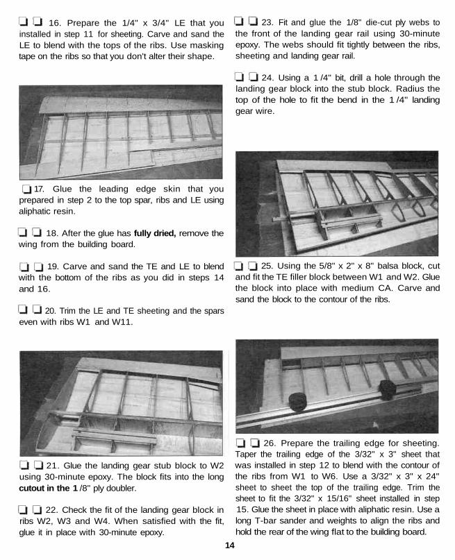
16. Prepare the 1/4" x 3/4" LE that youinstalled in step 11 for sheeting. Carve and sand theLE to blend with the tops of the ribs. Use maskingtape on the ribs so that you don't alter their shape.
17. Glue the leading edge skin that youprepared in step 2 to the top spar, ribs and LE usingaliphatic resin.
18. After the glue has fully dried, remove thewing from the building board.
19. Carve and sand the TE and LE to blendwith the bottom of the ribs as you did in steps 14and 16.
20. Trim the LE and TE sheeting and the sparseven with ribs W1 and W11.
23. Fit and glue the 1/8" die-cut ply webs tothe front of the landing gear rail using 30-minuteepoxy. The webs should fit tightly between the ribs,sheeting and landing gear rail.
24. Using a 1 /4" bit, drill a hole through thelanding gear block into the stub block. Radius thetop of the hole to fit the bend in the 1 /4" landinggear wire.
25. Using the 5/8" x 2" x 8" balsa block, cutand fit the TE filler block between W1 and W2. Gluethe block into place with medium CA. Carve andsand the block to the contour of the ribs.
21. Glue the landing gear stub block to W2using 30-minute epoxy. The block fits into the longcutout in the 1 /8" ply doubler.
22. Check the fit of the landing gear block inribs W2, W3 and W4. When satisfied with the fit,glue it in place with 30-minute epoxy.
26. Prepare the trailing edge for sheeting.Taper the trailing edge of the 3/32" x 3" sheet thatwas installed in step 12 to blend with the contour ofthe ribs from W1 to W6. Use a 3/32" x 3" x 24"sheet to sheet the top of the trailing edge. Trim thesheet to fit the 3/32" x 15/16" sheet installed in step15. Glue the sheet in place with aliphatic resin. Use along T-bar sander and weights to align the ribs andhold the rear of the wing flat to the building board.
14

27. After the glue has dried, turn the wingover and fit and glue a 3/32" x 15/16" x 24" sheetto the trailing edge between W5 and W11 withaliphatic resin. You will have to trim the 3/32" x 3"sheet installed in step 12.
28. Trim the LE and TE sheeting even with ribsW1 and W11. Sand the tip and root of the wing sothat it is smooth and flat.
29. Prepare the wingtip for sheeting. Fit andglue the 1 /8" die-cut balsa stiffeners to W11. Thesmaller stiffener should be positioned so that the topand bottom of the stiffener are flush with the top andbottom edges of rib W11. The larger stiffener shouldbe flush with the bottom of the rib and the topsurface of the top spar. Use a long straightedge tocheck that the top edge of the stiffeners are parallelto the top surface of the wing.
30. Cut the wing tip pattern from the center ofthis manual. Use the soft 1/8" x 3" x 36" balsasheet to cut the pieces for the wing tip to match thepattern, noting the grain direction. Glue the piecestogether and sand both surfaces flat and smooth.
31. Fit and glue the tip to the bottom of W11and the stiffeners. Fit and glue a filler block fromleftover balsa to the wing tip at the leading edge.
32. Cover the tops of ribs W7-W11 withmasking tape. Use a long T-bar sander to sand thetop of the wing tip so that it is parallel to the topsurface of the wing. See section A-A on the plansfor clarification.
33. Sheet the top of the wing tip using a3/32" x 3" x 30" balsa sheet.
34. Build the servo mounts between ribs W6and W7. Fit and glue the 1/8" x 1/2" x 4" plyservo rails. Space the rails to fit the servo you will beusing. Sheet the area around the servo using leftover3/32" x 3" so the covering will have a placeto adhere.
15

35. Build the left wing panel.
36. Prepare the wing panels for joining bycutting a 1/16" wide slot in front of and behind thespars on W1 as shown in the photo.
39. Measure the distance under the left wing tipat the bottom of rib W11. If it is 8-3/4" you haveexactly 6 degrees of dihedral in each panel. Don'tbe concerned if it is a little off as the dihedral angleis not at all critical. If it is off by more than 1 /2" youmight want to find out why, but you don't really needto fix it. When you are satisfied, glue the dihedralbraces to the left wing panel with 30-minute epoxy.
40. Using 3/32" x 3" x 36" balsa, sheet the topcenter of the wing from W3 to W3. The strength ofthe center section is important so we recommend thatyou use aliphatic resin. Note in the photo that weused one continuous piece across the entire centersection. This greatly increases the strength of thejoint, but it is a bit harder to install this way.
37. Test fit the 1/16" ply dihedral braces to thewing panels. Note that the shorter ply brace goes onthe forward side of the spars. When satisfied withthe fit, glue the braces to the right wing panel with30-minute epoxy. Remove the left panel and cleanoff any epoxy that seeped out from the joint.
38. After the epoxy has cured, slide the left panelback into position. Position the right panel flat on yourbuilding board and prop the left tip off the buildingboard. Don't you wish your surface was longer!!
1. Cover the right wing panel with wax paper.Cut the lower LE sheet from a 3/32" x 1/2" x 24"balsa stick and pin it to the plan.
16

2. Cut the lower TE sheet from a 3/32" x3/4" x 24" balsa stick and pin it to the plan.
3. Cut the LE from a 1 /4" x 3/4" x 24" balsastick. Glue and pin it to the 3/32" x 1/2" LE sheet.
4. Glue ribs 6 -11 into place.
I 5. Cut and glue two 1 /4" x 3/4" doublersticks where the aileron horn will mount.
6. Cut and glue hinge blocks into positionfrom a 1/2" x 5/8" x 24" balsa stick.
7. Remove the aileron from the plan. Carveand sand the top of the LE to match the taper of theribs. Taper the TE as well. Be careful as it is easy tosand into the ribs.
8. Glue the top 3/32" x 1/2" LE into place.
9. Glue the top 3/32" x 3/4" TE into place.
I 10. Fit and glue cap strips to the top andbottom of the aileron using 3/32" x 1/4" x 30"balsa sticks.
11. Sand the aileron to fit the wing. Mark thecenterline of the aileron leading edge along its entirelength. Using the cross section on the plans as areference, sand the leading edge to the "V" shapeshown. Make sure the "V" is large enough to allowfor the full up and down movement of the aileron.
NOTE: Do not bevel the TE of the wing to the "V"shape shown on the plan (this was drawn in error.)
12. Repeat steps 1 - 11 to build the left aileron.
13. Cut six additional hinge blocks from the 1 /2"x 5/8" balsa stick. Glue these into position along theinside edge of the TE of the wing opposite theposition of the blocks in the aileron.
1. Cut the stabilizer drawing from the wing planand place it on your building board. Cover the planwith wax paper.
2. Cut the trailing edge from 1/2" x 15/16" x 36"balsa and pin it in place over the plan.
3. Cut both leading edges from 1/2" x 15/16" x 36"balsa and set them aside.
4. Cut the tips from leftover 1/2" x 15/16"balsa. Glue and pin them in place.
5. Glue and pin the leading edges in place.17

11. Cut the elevator tips from 5/8" x 15/16" x 6"balsa. Glue and pin them into position.
12. Glue and pin the shaped balsa elevator rootsinto position.
6. Cut and fit the ribs from 1/8" x 1/2" x 30"balsa. Cut the longer ribs first. When satisfied withthe fit, glue them into position.
NOTE: It is important that the ribs fit the LE andTE well. It is not important that each rib fit the exactlocation shown on the plan.
7. Remove the stab from the plan and rough sandit to the shape shown in the cross section.
8. Mark the centerline of the stab on the back ofthe TE. Place a mark 5/8" on both sides of thecenterline. Place another set of marks 15" on bothsides of the centerline. These marks will be used toposition the elevators.
9. Sheet the stab with 1/16" x 3" x 30" balsa onboth the top and bottom. Do this with the stab flat onyour building board and use care not to twist it asyou glue the sheeting into place.
13. Cut some shims from 3/16" x 3/8" x 24" balsaand place them in position over the plan at the TE.
14. Cut the trailing edges from 1/4" x 3/4" x 30"balsa. Glue and pin them into position on top ofthe shims.
10. Build both elevators at the same time. Cut theleading edges from 5/8" x 1/2" x 36" balsa andpin them to the plans. The leftover 5/8" x 1/2"balsa will be used later to shim the stab when it ismounted to the fuselage.
15. Cut and fit the ribs from 1/8" x 5/8" x 30"balsa. Cut the longer ribs first. When satisfied withthe fit, glue them into position.
NOTE: It is important that the ribs fit the LE andTE well. It is not important that each rib fit the exactlocation shown on the plan.
16. Remove the elevators from the plan and roughsand them to the shape shown in the cross section.
17. Tack glue the elevators to the stab using thereference marks you made previously.
18

LI 18. Cut the tip shape from the plan and positionit over the stabilizer. Use the 15" marks, LE and TEas a guide. Cut the stab and elevator tips to shape.
1 19. Sand the assembly to its final shape.
20. Separate the elevators from the stab. Sandthe trailing edge of the stabilizer flat. Do not sand itto the "V" shape shown on the plan.
21. Mark the centerline of the elevator leadingedges along their entire length. Using the crosssection on the plans as a reference, sand the leadingedges to the "V" shape shown. Make sure the "V" isenough to allow for the full up and down movementof the elevators.
3. Cut the fin post (trailing edge) from3/8" x 15/16" x 30" balsa and pin it in position.
4. Cut the fin base from the 3/8" x 15/16" x 30"balsa and pin it into position. Glue all threepieces together.
5. Cut and fit the ribs from 3/16" x 3/8" x 24"balsa. Cut the longer ribs first. When satisfied withthe fit, glue them into position.
NOTE: It is important that the ribs fit the LE and TEwell. It is not important that each rib fit the exactlocation shown on the plan.
6. Remove the fin from the plan and rough sandit to the shape shown in the cross section.
7. Sheet the fin with 1/16" x 3" x 30" balsa onboth sides. Do this with the fin flat on your buildingboard and use care not to twist it as you glue thesheeting into place.
1. Cover the fin/rudder drawing with wax paper.
2. Cut the fin leading edge from 3/8" x 15/16" x 30"balsa and pin it in place over the plan.
8. Cut the rudder leading edge from1/2" x 15/16" x 36" balsa and pin it to the plans.
9. Cut the balance tab to shape from leftover1/2" x 15/16" balsa. Glue and pin it into position.
1 10. Laminate the four die-cut rudder base piecestogether with medium CA. Sand the edges flat andglue it into position.
LI 11. The trailing edge is built up from four 3/32"die-cut pieces to create one 3/16" thick piece.Laminate the parts together using the plan asa reference.
19

12. Build three shims from leftover 3/32" and1/16" balsa to create 5/32" thick shims. Place theshims into position over the plan and then glue andpin the TE into position.
13. Cut and fit the ribs from 3/16" x 1 /2" x 30"balsa. Cut the longer ribs first. When satisfied withthe fit, glue them into position.
NOTE: It is important that the ribs fit the LE and TEwell. It is not important that each rib fit the exactlocation shown on the plan.
14. Remove the rudder from the plan and roughsand it to the shape shown in the cross section.
15. Tack glue the rudder to the fin.
16. Sand the assembly to its final shape.
17. Separate the rudder from the fin. Sand thetrailing edge of the fin flat as shown on the crosssection of the plan.
18. Mark the centerline of the rudder leadingedge along its entire length. Using the cross sectionon the plans as a reference, sand the leading edgeto the "V" shape shown. Make sure the "V" isenough to allow for the full left and right movementof the rudder.
3. Cut two 1 /2" x 15/16" x 1 -1 /2" balsa blocksfrom leftover sticks and drill a 5/16" hole in thecenter of both blocks.
4. Slide the 5/16" x 5-1/4" wing dowelsthrough the holes in the LE and put a block on theend of each dowel. Align the blocks on the 1/16"ply dihedral braces so that the dowels are parallel tothe wing centerline. Glue the BLOCKS ONLY to thedihedral braces with 6-minute epoxy. Remove thedowels before the epoxy sets.
a
1. Find the eight 1 /8" die-cut balsa wing saddlepieces. Glue four pieces together using medium CAto form one wing saddle. Glue the other four piecestogether for the second saddle.
5. Fit the wing to the fuselage. Center the wingand mark the location of the dowels on bulkhead C.This is done by putting a pencil through the hole inthe LE and marking the bulkhead.
6. Remove the wing and drill 5/16" holes intobulkhead C.
7. Put the dowels into the wing and fit the wingback onto the fuselage. Make any adjustmentsneeded to get the dowels to fit properly into theholes in bulkhead C. When satisfied with the fit, gluethe dowels into the wing with 6-minute epoxy. Usecaution not to get any epoxy on the fuselage.
20

8. Align the wing squarely on the fuselage. This iseasily done using a piece of string as a guide. Put a pinin the tail of the fuselage on the centerline. Tie a loop inthe end of the string and place it over the pin. Move theother end of the string to one wing tip and put somemasking tape around the string. Draw an arrow on thetape where it reaches the wing tip. Now swing thestring over to the other wing tip. If the tip aligns with thearrow the wing is properly aligned. If not, adjust thewing's position and try again. Continue to adjust thewing until both wing tips are aligned with the arrow onthe tape. Secure the wing exactly in this position.
9. Drill two pilot holes for the 1/4-20 wing boltsusing a 13/64" bit. Drill the holes through the wingand into the ply wing bolt plate so that the holes willbe centered fore/aft in the plate.
10. Remove the wing from the fuselage. Tap theholes in the ply plate for the bolts with a 1 /4-20 tap.Apply a couple of drops of thin CA to the threads toharden them. After the CA has cured, run the tapthrough the threads to clean them up.
12. Enlarge the wing bolt holes in only the wingwith a 1/4" drill, drilling through the 1/16" plyplates as well.
13. Put some wax paper on the center of thewing where it will touch the fuselage and bolt thewing to the fuselage with the 1 /4-20 nylon bolts.
14. Fit a laminated wing saddle (that you built instep one) to each side of the fuselage. Sand itcarefully so that it fits the top surface of the wing.When satisfied with the fit, glue each to the fuselageside with 30-minute epoxy. Do not use 6-minuteepoxy as it will not allow you enough time toposition the clamps.
15. While you are waiting for the epoxy to cure,make two more wing LE skins just as you did in step2 of "BUILD THE WING."
16. Using leftover 1/4" x 1/2" balsa, glue afairing strip to the fuselage at the rear of the wingsaddle. This piece can be seen in the photo at step22 on page 22.
11. Fit the two 1/16" ply reinforcement plates forthe wing bolt holes into the wing. Glue these intoposition over the holes with 6-minute epoxy.
17. When the epoxy has cured, remove the wingfrom the fuselage. Sheet the bottom LE of bothwing panels.
21
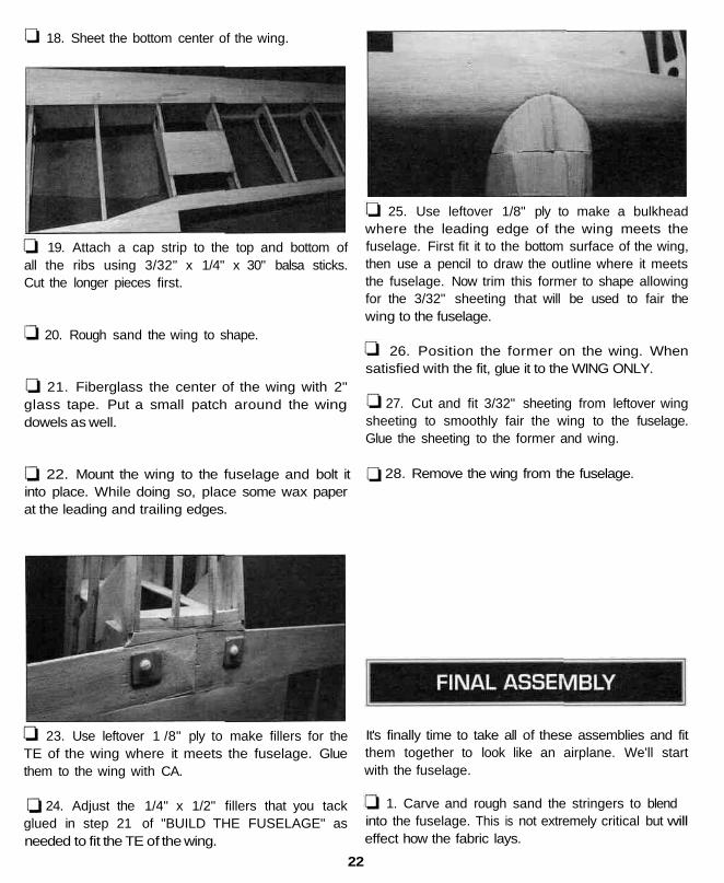
18. Sheet the bottom center of the wing.
19. Attach a cap strip to the top and bottom ofall the ribs using 3/32" x 1/4" x 30" balsa sticks.Cut the longer pieces first.
20. Rough sand the wing to shape.
21. Fiberglass the center of the wing with 2"glass tape. Put a small patch around the wingdowels as well.
22. Mount the wing to the fuselage and bolt itinto place. While doing so, place some wax paperat the leading and trailing edges.
25. Use leftover 1/8" ply to make a bulkheadwhere the leading edge of the wing meets thefuselage. First fit it to the bottom surface of the wing,then use a pencil to draw the outline where it meetsthe fuselage. Now trim this former to shape allowingfor the 3/32" sheeting that will be used to fair thewing to the fuselage.
26. Position the former on the wing. Whensatisfied with the fit, glue it to the WING ONLY.
27. Cut and fit 3/32" sheeting from leftover wingsheeting to smoothly fair the wing to the fuselage.Glue the sheeting to the former and wing.
28. Remove the wing from the fuselage.
23. Use leftover 1 /8" ply to make fillers for theTE of the wing where it meets the fuselage. Gluethem to the wing with CA.
24. Adjust the 1/4" x 1/2" fillers that you tackglued in step 21 of "BUILD THE FUSELAGE" asneeded to fit the TE of the wing.
It's finally time to take all of these assemblies and fitthem together to look like an airplane. We'll startwith the fuselage.
1. Carve and rough sand the stringers to blendinto the fuselage. This is not extremely critical but willeffect how the fabric lays.
22
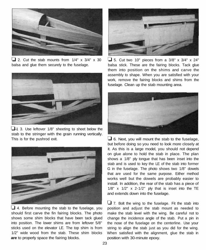
2. Cut the stab mounts from 1/4" x 3/4" x 30balsa and glue them securely to the fuselage.
1—1 3. Use leftover 1/8" sheeting to sheet below thestab to the stringer with the grain running vertically.This is for the pushrod exit.
4. Before mounting the stab to the fuselage, youshould first carve the fin fairing blocks. The photoshows some shim blocks that have been tack gluedinto position. The lower shims are from leftover 5/8"sticks used on the elevator LE. The top shim is from1/2" wide wood from the stab. These shim blocksare to properly space the fairing blocks.
5. Cut two 10" pieces from a 3/8" x 3/4" x 24"balsa stick. These are the fairing blocks. Tack gluethem into position on the shims and carve theassembly to shape. When you are satisfied with yourwork, remove the fairing blocks and shims from thefuselage. Clean up the stab mounting area.
6. Next, you will mount the stab to the fuselage,but before doing so you need to look more closely atit. As this is a large model, you should not dependon glue alone to hold the stab in place. The planshows a 1/8" ply tongue that has been inset into thestab and is used to key the LE of the stab into formerG in the fuselage. The photo shows two 1/8" dowelsthat are used for the same purpose. Either methodworks well but the dowels are probably easier toinstall. In addition, the rear of the stab has a piece of1/8" x 1/2" x 2-1/2" ply that is inset into the TEand extends down into the fuselage.
7. Bolt the wing to the fuselage. Fit the stab intoposition and adjust the stab mount as needed tomake the stab level with the wing. Be careful not tochange the incidence angle of the stab. Put a pin inthe nose of the fuselage on the centerline. Use yourstring to align the stab just as you did for the wing.When satisfied with the alignment, glue the stab inposition with 30-minute epoxy.
23

8. Glue the fin and fin fairing blocks into positionwith 30-minute epoxy. Be sure the fin isperpendicular to the stab and aligned with thefuselage centerline.
9. When the epoxy has cured, remove the wing.Fill in and blend any areas that need it with leftoverwood and hobby filler.
10. Mount the tailwheel bracket to the fuselagewith three #2 sheet metal screws. Use leftover woodand hobby filler to blend it to the fuselage.
11. Finish the cockpits. The cockpit area wasdesigned to be structure free so you can add asmuch detail as desired. The simplest is to glue incockpit decks as shown on the plans and add acouple of Williams Brothers pilots glued to the decks.Fourmost makes cockpit coaming that dresses up theopenings nicely. The kit includes two instrumentpanel decals which can be positioned on thebulkheads, or you can purchase separate instrumentpanels from Midwest Products. The kit also includes25" of 1 /4" dowel to build the roll cage between thecockpits. Details in the cockpit area will really dressup the appearance of your model.
Position the mount on the plans at the firewall thenlocate the engine on the mount to fit the front of thecowl properly. Check the position on the model to besure blind nuts and bolts will clear the structure.
NOTE: If you will be using a chainsaw-type engine,such as the G-23, your engine will need to bespaced out from the firewall. On one of ourprototypes we used a 1-1/2" block of wood thatwas bolted to the firewall with 10-32 x 2" bolts.
13. Glue the firewall to the fuselage with30-minute epoxy. For added security you can pin thefirewall to the fuselage if desired. Drill small holesthrough the sides of the fuselage into the firewall andepoxy in small dowels or toothpicks.
14. Once the epoxy has cured, install yourengine and mount on the firewall.
15. Fit the cowl. The plastic cowl comes in halvesand needs to be glued together. The kit includes astrip of plastic that is used to reinforce the joint onthe inside. Thin CA works well for this. When youhave glued the cowl together, cut a small hole wherethe prop needs to exit the front. Slip the cowl ontothe fuselage. Enlarge the hole as needed to clear theengine thrust washer. As you continue to fit the cowlto the fuselage and engine you may need to removeand reinstall the engine several times. We havefound that using a piece of cardboard taped to theside of the fuselage is the easiest way to locate thecutout for the engine. Tape the cardboard to thefuselage and cut an opening in it to fit your engine,remove the engine, install the cowl and transfer thecutout to the cowl. If you go slowly and remove alittle material each time from the cowl you will berewarded with a good looking cowl.
12. Time to mount your engine. Before you gluethe firewall into position, you should add somereinforcing sticks to the inside of the fuselage asshown in the above photo. There should be ampleleftover 1 /4" x 3/8" basswood sticks for this purpose.Glue them into position with 30-minute epoxy. Whileyou are waiting for the epoxy to cure you can mountyour engine to the engine mount you have chosen.
16. When you are satisfied with the fit of thecowl remove it and glue the four hardwood blocksinto place on the fuselage. The blocks are of differentsizes so a little fitting will be needed. They should beclose to fitting from the engine box to the fuselagecurve at "B." After the blocks are glued into position,sand them to blend to the curve of the cowl.
24

7. To drill the mounting holes in the cowl use thecardboard technique again. Tape some cardboardto the fuselage side and mark the center of themounting blocks. Slip the cowl into position andmark the location of the holes. Drill 3/32" holesthrough the cowl and blocks, then remove the cowland enlarge the holes in only the cowl to 1/8".Mount the cowl with #6 x 1 /2" sheet metal screws.
18. Hinge the control surfaces. The kit includes ahinge strip from which you can cut CA hinges, oryou can use other hinges of your choice. Thefollowing general guidelines will discuss hinging. Wewill discuss hinging the elevator but the sameprocess is used to hinge the rudder and ailerons.
A. If you have not already done so, mark thecenterline of the TE of the stab.
B. The LE of the elevators has already beensanded to a "V," so this will be used asthe centerline.
C. Using the plan as a reference, mark thelocations of the hinges to be installed.
CUT HINGE SLOTWITH HOBBY KNIFEAND No. 11 BLADE
D. Use a hobby knife with a #11 blade to makethe hinge slots. The first cut should be ashallow slit to establish the hinge slot location.After the first cut, make several more cutsgoing slightly deeper each time. Move theknife from side to side and widen the slot asyou cut.
E. Test join the elevators to the stab with thehinges in place. DO NOT glue until later.
F. Perform the same process for the rudder and forthe ailerons.
AFTER you have completely covered and finishedyour model, perform the following:
A. Use your hobby knife and a sharp #11 bladeto remove a small strip of covering from thehinge slots to expose them.
THE CA WICKSALONG THE "TUNNELS"
TO THE ENTIREHINGE SURFACE
B. Drill a 3/32" hole in the center of all the hingeslots to allow the CA to fully penetrate. This isbest done with a high-speed tool such as apowered hand tool. If you use a drill, removeslivers of balsa wood from the hinge slots witha hobby knife after you drill the holes.
25

TEMPORARY PINTO KEEP HINGE
C. Join the elevator to the stab with the hinges. Ifthe hinges will not stay centered, insert a pinthrough the center of the hinge, then join thesurfaces and remove the pins.
D. Confirm that the ends of the elevator align withthe ends of the stab, that the hinges arecentered and there is approximately a 1 /32"gap between the TE of the stab and the LE ofthe elevator. A small gap is desirable so youdo not inadvertently glue the elevator to thestab with residual CA.
E. Carefully apply 6 drops of thin CA to each sideof all the hinges. Keep a tissue handy to wipeaway excess CA. If you spill a few drops ofCA on the MonoKote film you can use CADebonder (GPMR6039) to remove it. Or, waituntil the CA fully cures, then carefully lift it offwith a hobby knife blade.
F. Let the CA fully cure, then flex the elevatorseveral times to check the movement.
G. Use the same procedure to hinge the rudderand ailerons.
19. Fit and install the landing gear.
Do not use accelerator on any of the hinges. Do notglue the hinges with anything other than thin CAand do not attempt to glue one half of the hinge ata time with medium or thick CA. They will not besecure and the control surfaces could separatewhile the model is flying.
You may cover and finish your model now if youdesire. We prefer to install the radio before finishing sowe don't add any hanger rash to our finished model.Our radio installation consisted of the following:
A. One S-148 size servo for each aileron. IMAArules may require higher torque servos.
B. One high torque servo for each elevator, with aseparate pushrod for each.
C. One quarter-scale servo for the rudder, with apull-pull system.
D. One S-148 size servo for the throttle.
E. We used a 1200 Mah battery pack to allow forthe additional servo drain.
While this is a large aircraft, it does not fly very fast.We have found that the above installation hasworked very well.
This model will go into uncontrollable fits of sadness ifit isn't covered with fabric. Fortunately, Coverite 21stCentury prepainted fabric will eliminate this tendencyand looks great! You will need 15 feet of Cub Yellow(COVQ0304), 15 feet of Mid Blue (COVQ0412),2 feet of Light Red (COVQ0302), 2 feet of White(COVQ0301) and 3 feet of Black (COVQ0310).
After you have finished covering, finish the hingeinstallation as covered previously.
To install your windshields, cut and fit them to thefuselage. Cut the covering where they will be gluedto the fuselage so that the windshields can beadhered to the wood. Use tape or paint to detail thepanel lines.
Install your fuel system. We used a 16 oz. tank(GPMQ4107) and a refueling valve (GPMQ4160).Don't forget to fuelproof the engine and tank area.
CENTERED
26

Measure the throws at the widest part of thetrailing edge of the rudder, ailerons and elevator.After a few flights you may change the throws tosuit your flight style or the weather conditions.
We recommend the following control surfacethrows:
Elevator 1 -1 /8" up and down
Rudder 2" left and right
Ailerons 3/4" up and down
Throttle: Set the throttle so that at "high stick" thecarburetor barrel is fully open and at low stickwith full to half throttle trim, the carburetor barrelis nearly closed. At this position the engine shouldrun reliably at a low RPM (idle). To shut the engineoff, decrease the throttle trim tab.
(GPMR2400). If the tail drops, shift the receiverand/or battery pack forward (if possible) to balancethe model. If the nose drops, shift the receiverand/or battery pack aft. If possible arrange thebattery pack and receiver to achieve balance butmake sure they remain secure in the fuselage so theycannot shift during flight or a rough landing. If youmust add additional weight to the nose or tail of thePT-19 to achieve balance use Great Planes adhesivelead weights (GPMQ4485). An alternate to stick-onnose weight (if your model is tail heavy) is a GreatPlanes brass spinner nut (GPMQ4640). It has1/4-28 threads so it will fit most engines.
This section is IMPORTANT and must NOT be omitted.A model that is not properly balanced will beunstable and possibly unflyable.
1. Check the balance point with all componentsinstalled in the model and the fuel tank empty. Attachthe wing to the fuselage, then accurately mark thebalance point on the top of both wing halves next tothe fuselage. The balance point is shown on the planand is 4-3/8" (111 mm) aft of the leading edge.
4-3/8"
2. Lift the model with your fingers at the balancepoint or use the Great Planes CG Machine
Balance Your PropellersBalancing the propeller seems like one of thosethings that you can skip, but many problems are theresult of vibration caused by an unbalancedpropeller. Nuts and bolts can vibrate loose andvibration can damage delicate radio componentsinside your receiver and servos. Vibration can evendamage the delicate glow plug element which couldresult in an engine that is difficult or impossible tostart. Purchase a Top Flite Precision MagneticBalancer™ (TOPQ5700) or a Great Planes fingertipprop balancer (GPMQ5000) to accurately balanceyour propellers.
Charge Your BatteriesFollow the battery charging instructions in theinstruction manual that came with your radio controlsystem. You should always charge your batteries thenight before you fly.
Ground Check Your ModelInspect all nuts, screws and wheel collars. Make sureyou install the screw that holds the servo arm ontothe servos and the servo cords are securelyconnected to the receiver. If you are not thoroughlyfamiliar with R/C models, ask an experiencedmodeler to inspect your radio installation and make
27

sure the control surfaces respond correctly. Theengine must be "broken-in" according to the enginemanufacturer's recommendations for break-in. Referto the Engine Safety Precautions on the next pagebefore you start your engine. After you run theengine on the model make sure all screws remaintight, the hinges are secure and the prop is on tight.
Range Check Your RadioCheck the operational range of the radio before thefirst flight. Before you turn your radio on, the firstthing you always must do is make sure no one elseis on you frequency (channel). Most model flyingfields utilize frequency control so familiarize yourselfwith their system. Collapse your transmitter antennaand turn on the transmitter, then the receiver(preferably the receiver should never be on by itself).You should be able to walk at least 100 feet awayfrom the model and still have control. Have anassistant stand by your model and tell you what thecontrol surfaces are doing while you operate themfrom the transmitter.
Repeat this test with an assistant holding the modeland the engine running at various speeds. If thecontrol surfaces do not always respond correctly,don't fly! Find and correct the problem first. Look forloose servo connections or corrosion, loose fastenersthat may cause vibration, a defective on/off switch,low battery voltage or a defective cell, a damagedreceiver antenna or a receiver crystal that may havebeen damaged from a previous crash.
Get help from an experienced modeler when youlearn to operate engines.
Use safety glasses when you operate model engines.Do not run the engine near loose gravel or sand; thepropeller may throw loose material in your faceor eyes.
When you start and run the engine keep your faceand body as well as all spectators away from theplane of rotation of the propeller.
Keep loose clothing, shirt sleeves, ties, scarfs, longhair or loose objects away from the prop. Beconscious of pencils, screwdrivers or other objectsthat may fall out of your shirt or jacket pockets.
Use a "chicken stick" or electric starter and followthe instructions to start your engine.
Ask an assistant to hold the model from the rearwhile you start the engine and operate the controls.
Make all engine adjustments from behind therotating propeller.
The engine gets hot! Do not touch the engine duringor immediately after you operate it. Make sure fuellines are in good condition so fuel will not leak ontoa hot engine and cause a fire.
To stop the engine, close the carburetor barrel (rotor)or pinch the fuel line to discontinue the fuel flow. Donot use your hands, fingers or any body part to stopthe engine. Never throw anything into the prop of arunning engine.
NOTE: Failure to follow these safety precautions maycause severe injury to yourself and others.
Store model fuel in a safe place away from highheat, sparks or flames. Do not smoke near theengine or fuel as it is very flammable. Engineexhaust gives off a great deal of deadly carbonmonoxide so do not run the engine in a closedroom or garage.
The best place to fly your R/C model is at an AMA(Academy of Modef Aeronautics) chartered club field.Ask your hobby dealer or the AMA if there is a club inyour area and join it (the address and telephonenumber for the AMA is listed on page 3 of thisinstruction book). Club fields exist to make your R/C
28

flying safe and enjoyable. We recommend that you jointhe AMA and a local club so you may have a safeplace to fly and insurance in case of a flying accident.
If a club flying site is not available, find a large, grassyarea at least 6 miles away from houses, buildings,streets and other R/C activity like boats and cars.Avoid flying R/C models near traffic or areas such asparks, school yards, office building lawns, etc. thatmay attract unrestrained observers (wild kids). If youare a beginner, you are busy enough concentrating onyour model without having to answer lots of questionsand performing crowd control.
We highly recommend that you get an experiencedmodeler to assist you with your flight training. Anexperienced modeler can take your PT-19 up for thefirst time and make sure it performs correctly, thengive you valuable flight instruction. He can hand youthe transmitter when the PT-19 has climbed to a safealtitude or connect your transmitter to his if both ofyour systems have trainer cord or "buddy box"capability. Assistance from an experienced modelerwill make your modeling "career" progress faster(and cheaper). We do, however realize that somemodelers are determined to learn on their own orare not in a location where an instructor or flyingclub is available. Therefore, we have provided thefollowing information to give you an idea of what toexpect on your first flight with your PT-19. Both flyerswho plan to set out on their own and fliers who willhave the help of an instructor should carefully readthe following information.
First flight attempts should be reserved for calm dayswhen the wind speed is less than five mph. Alwaystakeoff (and land) into the wind. Check theoperation of all controls just before takeoff. This willeliminate the possibility of overlooking reversed ordisconnected controls (it happens). Your PT-19 is amodel of the full size flight training aircraft, whichwas a low powered, gentle and forgiving aircraft.Your model flies much like the full size aircraft it ismodeled after. It performs in a very scale-likemanner with the recommended engines. Do notexpect it to fly like sport models you may haveflown previously.
As you apply power on takeoff you will need toapply a slight amount of right rudder to compensatefor engine torque and propeller "P" effect. The tailwill rise almost immediately, indicating that the tailsurfaces have gained effectiveness. Allow the modelto continue to accelerate until it has reached flyingspeed. Use as much of the available runway as youcan. Then, gently apply some up elevator. Your PT-19 should slowly lift from the runway. Continuestraight ahead until you have accelerated to a safeflying speed. Your first turn will show that this modeldoes indeed fly much like the full size trainer as theroll rate is intended for new pilots learning to fly.
The full size PT-19 was a trainer for Army Air CorpsPilots. It was designed to teach takeoffs, landings,turns, stalls, spins and gentle aerobatics. Beingrelatively low powered, it does not have a high rateof climb and has poor vertical performance. To gainairspeed for a loop it was necessary to dive for abrief period. Barrel rolls were slow, teaching rollcoordination. If you fly your model in the same wayyou will be very pleased with it's performance.
Before attempting your first landing you should firsttry some slow flight and stalls to become familiarwith the PT-19's slow speed characteristics. You willprobably find the model slows down quicker andrequires more power than you are used to. Expect tocarry some power on final approach as the modelwill quickly loose speed with a nose high attitude.Remember that aircraft of the PT-19's era had limitedlow speed control effectiveness, especially for theailerons. The rudder is very effective however.Continue to carry power and speed until you initiatethe flare, then reduce power and allow the model togently settle to the ground. If you must go around,add power and accelerate straight ahead. Do notattempt to climb or turn until you have accelerated toa save flying speed.
We hope you enjoy the realistic looks andperformance of your PT-19.
29

Here is a short list of terms and definitions so you'llknow what they're talking about at the flying field.
Ailerons -Hinged control surfaces located on thetrailing edge of the wing, one on each side, whichprovide control of the airplane about the roll axis.The control direction is often confusing to first timemodelers. For a right roll or turn, the right handaileron is moved upward and the left hand ailerondownward, and vice-versa for a left roll or turn.
Angle of attack -The angle that the wing penetratesthe air. As the angle of attack increases so does liftand drag, up to a point.
ARF -A prefabricated model - Almost Ready to Fly.
Buddy Box -Two similar transmitters that are wiredtogether with a "trainer cord." This is most usefulwhen learning to fly—it's the same as having dualcontrols. The instructor can take control by using the"trainer switch" on his transmitter.
CA -Abbreviation for "Cyanoacrylate." An instanttype glue that is available in various viscosities (Thin,Medium, Thick, and Gel). These glues are ideal forthe assembly of wood airplanes and other materials.
NOTE: Most CA glues will attack styrofoam.
Carburetor -The part of the engine which controlsthe speed or throttle setting and lean/rich mixturevia setting of the needle valve.
CG -"Center of Gravity"- For modeling purposes, thisis usually considered the point at which the airplanebalances fore to aft. This point is critical in regards tohow the airplane reacts in the air. A tail-heavy planewill be very snappy but generally very unstable andsusceptible to more frequent stalls. If the airplane isnose heavy, it will tend to track better and be lesssensitive to control inputs, but will generally drop itsnose when the throttle is reduced to idle. This makesthe plane more difficult to land since it takes moreeffort to hold the nose up. A nose heavy airplane willhave to come in faster to land safely.
Charge Jack -The plug receptacle of the switchharness into which the charger is plugged to chargethe airborne battery. An expanded scale voltmeter(ESV) can also be plugged into it to check batteryvoltage between flights. It is advisable to mount thecharge jack in an accessible area of the fuselage soan ESV can be used without removing the wing.
Charger -Device used to recharge batteries andusually supplied with the radio if NiCd batteriesare included.
Chicken Stick -A hand-held stick used to flip start amodel airplane engine.
Clunk -A weighted fuel pick-up used in a fuel tankto assure the intake line is always in fuel.
Dead Stick -A term used to describe unpoweredflight (glide) when the engine quits running.
Dihedral -The V-shaped bend in the wing. Typically,more dihedral causes more aerodynamic stability inan airplane, and causes the rudder to control boththe roll and yaw axis. This is why some trainers andsailplanes require only 3 channels of radio control.
Ding -Minor dent or damage to the structure. Also,a nick in a prop. Dinged props must be replaced.
Down thrust -Downward angle of the enginerelative to the centerline of the airplane. Down thrusthelps overcome the normal climbing tendency of flatbottom wings.
Electric Starter -A hand-held electric motor used forstarting a model airplane engine. Usually poweredby a 12-volt battery.
Elevator -Hinged control surface located at thetrailing edge of the horizontal stabilizer, whichprovides control of the airplane about the pitch axisand causes the airplane to climb or dive. The correctdirection of control is to pull the transmitter elevatorcontrol stick back, toward the bottom of thetransmitter, to move the elevator upward, whichcauses the airplane to climb, and vice versa to dive.
30

Epoxy -A two-part resin/hardener glue that isextremely strong. It is generally available in 6 and30-minute formulas. Used for critical points in theaircraft where high strength is necessary.
Expanded Scale Voltmeter (ESV) -Device used toread the battery voltage of the on-board batterypack or transmitter battery pack.
Field charger -A fast battery charger designed towork from a 1 2-volt power source, such as acar battery.
Flaps -Hinged control surface located at the trailingedge of the wing inboard of the ailerons. The flapsare lowered to produce more aerodynamic lift fromthe wing, allowing a slower takeoff and landingspeed. Flaps are often found on scale models, butusually not on basic trainers.
Flare -The point during the landing approach inwhich the pilot gives ah increased amount of upelevator to smooth the touchdown of the airplane.
Flight Box -A special box used to hold and transportall equipment used at the flying field.
Flight Pack -or Airborne pack - All of the radioequipment installed in the airplane, i.e.. Receiver,Servos, Battery, Switch harness.
Flutter -A phenomenon whereby the elevator rudder,or aileron control surface begins to oscillate violentlyin flight. This can sometimes cause the surface tobreak away from the aircraft and cause a crash.There are many reasons for this, but the mostcommon are excessive hinge gap or excessive "slop"in the pushrod connections and control horns. If youever hear a low-pitched buzzing sound, reducethrottle and land immediately.
Fuel Pick-Up Line -The fuel line in the fuel tankthrough which fuel travels to the carburetor. Typicallya flexible tube with a weight or "Clunk" on the endwhich allows it to follow the fuel with changes inaircraft attitude. This is the line through which thetank is filled.
Fuselage -The body of an airplane.
Glow Plug -The heat source for igniting the fuel/airmixture in the engine. When starting the engine abattery is used to heat the filament. After the engineis running, the battery can be removed. The wirefilament inside the plug is kept hot by the"explosions" in the engine's cylinder.
Glow Plug Clip/Battery -A 1.2-volt battery, which isconnected to the glow plug on a model airplaneengine for starting. The battery is removed once theengine is running steadily.
Hit (or to be hit) -Sudden radio interference whichcauses your model to fly in an erratic manner. Mostoften caused by someone turning on a radio that ison your frequency, but can be caused by other radiosources miles away.
Horizontal Stabilizer -The horizontal tail surface atthe back of the fuselage which providesaerodynamic pitch stability to the airplane.
Lateral Balance -The left-right or side-to-sidebalance of an airplane. An airplane that is laterallybalanced will track better through loops andother maneuvers.
Leading Edge (LE) -The very front edge of the wingor stabilizer. This is the edge that hits theair first.
Muffler -A device attached to the exhaust stack ofthe engine to reduce noise and increase back-pressure which helps low speed performance.
Note: Most R/C Clubs require the use of mufflers.
Needle Valve -Adjustment on a carburetor used toset proper fuel/air mixture. Some carburetors haveseparate needle adjustments for low and highthrottle. Typically, turning the needle clockwise(screwing in) leans the mixture (less fuel), and viceversa. However, there are a few exceptions—refer tothe engine manufacturer's instructions.
31

NiCd -Nickel Cadmium battery. Rechargeablebatteries which are typically used as power for radiotransmitters and receivers.
Nitro -Nitromethane, a fuel additive which increasesa model engine's ability to idle low and improveshigh speed performance. Ideal nitro content variesfrom engine to engine. Refer to the enginemanufacturer's instructions for best results. Nitrocontent in fuel is indicated by the percent of the fuel.
Ni-starter -A self-contained battery and glow plugclip, used when starting the engine.See "glow plug clip."
Power panel -12-volt distribution panel that providescorrect voltage for accessories like glow-plug clips,fuel pumps and electric starters. Usually mounted on afield box and connected to a 12-volt battery.
Prop pitch -Props are designated by two numbers,for instance 10 - 6. The first number is the prop'slength, 10". The second number is the pitch or angleof the blades. The 6 represents the distance thepropeller will move forward in one revolution, in thiscase 6".
Receiver (Rx) -The radio unit in the airplane whichreceives the transmitter signal and relays the controlto the servos. This is somewhat similar to the radioyou may have in your family automobile, except theradio in the airplane perceives commands from thetransmitter, while the radio in your car perceivesmusic from the radio station.
Rudder -Hinged control surface located at thetrailing edge of the vertical stabilizer, which providescontrol of the airplane about the Yaw axis andcauses the airplane to Yaw left or right. Left ruddermovement causes the airplane to Yaw left, and rightrudder movement causes it to Yaw right.
Servo -The electro-mechanical device which moves thecontrol surfaces or throttle of the airplane according tocommands from the receiver. The radio device whichdoes the physical work inside the airplane.
Slop -Unwanted, excessive free movement in acontrol system. Often caused by a hole in a servoarm or control horn that is too big for the pushrodwire or clevis pin. This condition allows the controlsurface to move without transmitter stick movement.A/so, see "flutter."
Solo -Your first totally unassisted flight that results ina controlled land ing.
Spinner -The nose cone which covers the hub orthe propeller.
Sport Airplane -A model which possesses someattributes of many of the specialty airplanes and arebest for general flying as they are the most versatileand durable.
Stall -What happens when the angle of attack is toogreat to generate lift regardless of airspeed. (Everyairfoil has an angle of attack at which it generatesmaximum lift — the airfoil will stall beyond this angle).
Trainer Airplane -A model designed to be inherentlystable and fly at low speeds, to give first-timemodelers time to think and react as they learn to fly.
Trailing Edge (TE) -The rearmost edge of the wingor stabilizer.
Transmitter fTx) -The hand-held radio controller. Thisis the unit that sends out the commands that you input.
Vertical Fin -The non-moving surface that isperpendicular to the horizontal stabilizer andprovides yaw stability. This is the surface to whichthe rudder attaches.
Wheel Collar -A small, round retaining device usedto keep a wheel from sliding off an axle.
Z-Bend -A simple Z-shaped bend in the wire end ofa pushrod, which is used to attach the pushrod to aservo output arm.