
Real-Time Tracking of Multiple Sound Sources by ...€¦ · Real-Time Tracking of Multiple Sound...
8
Real-Time Tracking of Multiple Sound Sources by Integration of In-Room and Robot-Embedded Microphone Arrays Kazuhiro Nakadai ∗ , Hirofumi Nakajima † , Masamitsu Murase ‡ , Hiroshi G. Okuno ‡ , Yuji Hasegawa ∗ and Hiroshi Tsujino ∗ ∗ HONDA Research Institute Japan Co., Ltd., 8-1 Honcho, Wako-shi, Saitama 351-0114, JAPAN † Nittobo Acoustic Engineering Co., Ltd., 1-13-12 Midori, Sumida-ku, Tokyo 130-0021, JAPAN ‡ Graduate School of Informatics, Kyoto University, Yoshidahonmachi, Sakyo-ku, Kyoto 606-8501, JAPAN {nakadai, yuji.hasegawa, tsujino}@jp.honda-ri.com, [email protected], {murase, okuno}@kuis.kyoto-u.ac.jp Abstract— Real-time and robust sound source tracking is an important function for a robot operating in a daily environment, because the robot should recognize where a sound event such as speech, music and other environmental sounds originate from. This paper addresses real-time sound source tracking by real- time integration of an in-room microphone array (IRMA) and a robot-embedded microphone array (REMA). The IRMA system consists of 64 ch microphones attached to the walls. It localizes multiple sound sources based on weighted delay-and-sum beam- forming on a 2D plane. The REMA system localizes multiple sound sources in azimuth using eight microphones attached to a robot’s head on a rotational table. The localization results are integrated to track multiple sound sources by using a particle filter in real-time. The experimental results show that particle filter based integration improved accuracy and robustness in multiple sound source tracking even when the robot’s head was in rotation. I. I NTRODUCTION Integration of various information improves robustness and accuracy of perception. In human perception, plenty of ev- idence on such integration has been reported. For example, temporal integration [1], McGurk effect in speech recognition [2] and audio-visual localization [3] are commonly known as the evidence on audio-visual integration, Also, in sound source localization, two different cues such as interaural phase difference and interaural intensity difference are integrated to robustly localize sounds with wide ranges of frequencies [4]. Some researchers reported auditory-visually integrated systems inspired by the evidence to deal with real-world problems [5], [6]. This means that integration is essential for a robot which is expected to work in the real world to improve the robustness of perception. Actually, we have been reported a robot audition system that localizes, separates and recognizes a mixture of speech uttered by three persons simultaneously by using audio-visual integration, and showed the effectiveness of the system in application to human-robot communication [9]. The system, however, relied on only two microphones at the position of the robot’s ears. The system can use not only mi- crophones embedded in a robot, but also those deployed in the surrounding environments to improve the performance. Thus, we propose spatial integration, which means the integration of multiple microphone arrays for better sound processing. A. Two Types of Microphone Arrays and Their Integration We considered two types of microphone arrays – a robot- embedded microphone array, and an in-room microphone array (hereafter, referred to as REMA and IRMA, respectively). REMA is promising to improve robot audition directly. Actu- ally, some work [7], [8] has been reported that an 8 ch REMA system has better performance for sound source localization and separation than a binaural approach such as [9]. However, it has two defects. One is that the performance, while the robot is in motion, is worse because it is difficult to synchronize signal capturing with motion precisely and to adapt to acoustic environmental changes after a robot’s motion. The other is that it does not give any solution to extract accurate information from a distant talker due to the small size of the microphone array. On the other hand, IRMA can solve these problems, because a microphone array is always stationary, and the microphones are distributed throughout the room. Since this type of microphone array can compensate for the above two defects, it is effective to improve robot audition indirectly. Large size microphone arrays for sound source localization and separation reported in [10], [11], [12] can be used for this purpose. For REMA, we reported a binaural auditory system [9] and Geometric Source Separation (GSS) based microphone array [13] so far. Although both systems work in real-time, they were not robust enough against acoustic environmental changes. In this paper, we adopt an adaptive beamformer, Multiple Signal Classification (MUSIC) [14] for our 8 ch REMA system. It has better performance for sound source localization and separation than that of the above non- adaptive methods, because it can adapt to some environmental changes. In addition, it can work in real-time by making use of pre-measured impulse responses. As an algorithm for IRMA, we proposed weighted delay- and-sum beamforming (WDS-BF) [15]. This algorithm can estimate directivity patterns and locations of sound sources. 1-4244-0259-X/06/$20.00 ©2006 IEEE
Transcript of Real-Time Tracking of Multiple Sound Sources by ...€¦ · Real-Time Tracking of Multiple Sound...

Real-Time Tracking of Multiple Sound Sources byIntegration of In-Room and Robot-Embedded
Microphone ArraysKazuhiro Nakadai∗, Hirofumi Nakajima†, Masamitsu Murase‡,
Hiroshi G. Okuno‡, Yuji Hasegawa∗ and Hiroshi Tsujino∗
∗ HONDA Research Institute Japan Co., Ltd., 8-1 Honcho, Wako-shi, Saitama 351-0114, JAPAN† Nittobo Acoustic Engineering Co., Ltd., 1-13-12 Midori, Sumida-ku, Tokyo 130-0021, JAPAN
‡ Graduate School of Informatics, Kyoto University, Yoshidahonmachi, Sakyo-ku, Kyoto 606-8501, JAPAN
{nakadai, yuji.hasegawa, tsujino}@jp.honda-ri.com, [email protected], {murase, okuno}@kuis.kyoto-u.ac.jp
Abstract— Real-time and robust sound source tracking is animportant function for a robot operating in a daily environment,because the robot should recognize where a sound event such asspeech, music and other environmental sounds originate from.This paper addresses real-time sound source tracking by real-time integration of an in-room microphone array (IRMA) and arobot-embedded microphone array (REMA). The IRMA systemconsists of 64 ch microphones attached to the walls. It localizesmultiple sound sources based on weighted delay-and-sum beam-forming on a 2D plane. The REMA system localizes multiplesound sources in azimuth using eight microphones attached toa robot’s head on a rotational table. The localization results areintegrated to track multiple sound sources by using a particlefilter in real-time. The experimental results show that particlefilter based integration improved accuracy and robustness inmultiple sound source tracking even when the robot’s head wasin rotation.
I. INTRODUCTION
Integration of various information improves robustness andaccuracy of perception. In human perception, plenty of ev-idence on such integration has been reported. For example,temporal integration [1], McGurk effect in speech recognition[2] and audio-visual localization [3] are commonly knownas the evidence on audio-visual integration, Also, in soundsource localization, two different cues such as interaural phasedifference and interaural intensity difference are integratedto robustly localize sounds with wide ranges of frequencies[4]. Some researchers reported auditory-visually integratedsystems inspired by the evidence to deal with real-worldproblems [5], [6]. This means that integration is essential for arobot which is expected to work in the real world to improvethe robustness of perception. Actually, we have been reporteda robot audition system that localizes, separates and recognizesa mixture of speech uttered by three persons simultaneously byusing audio-visual integration, and showed the effectiveness ofthe system in application to human-robot communication [9].
The system, however, relied on only two microphones at theposition of the robot’s ears. The system can use not only mi-crophones embedded in a robot, but also those deployed in thesurrounding environments to improve the performance. Thus,
we propose spatial integration, which means the integrationof multiple microphone arrays for better sound processing.
A. Two Types of Microphone Arrays and Their Integration
We considered two types of microphone arrays – a robot-embedded microphone array, and an in-room microphone array(hereafter, referred to as REMA and IRMA, respectively).REMA is promising to improve robot audition directly. Actu-ally, some work [7], [8] has been reported that an 8 ch REMAsystem has better performance for sound source localizationand separation than a binaural approach such as [9]. However,it has two defects. One is that the performance, while the robotis in motion, is worse because it is difficult to synchronizesignal capturing with motion precisely and to adapt to acousticenvironmental changes after a robot’s motion. The other is thatit does not give any solution to extract accurate informationfrom a distant talker due to the small size of the microphonearray. On the other hand, IRMA can solve these problems,because a microphone array is always stationary, and themicrophones are distributed throughout the room. Since thistype of microphone array can compensate for the above twodefects, it is effective to improve robot audition indirectly.Large size microphone arrays for sound source localizationand separation reported in [10], [11], [12] can be used forthis purpose. For REMA, we reported a binaural auditorysystem [9] and Geometric Source Separation (GSS) basedmicrophone array [13] so far. Although both systems workin real-time, they were not robust enough against acousticenvironmental changes. In this paper, we adopt an adaptivebeamformer, Multiple Signal Classification (MUSIC) [14] forour 8 ch REMA system. It has better performance for soundsource localization and separation than that of the above non-adaptive methods, because it can adapt to some environmentalchanges. In addition, it can work in real-time by making useof pre-measured impulse responses.
As an algorithm for IRMA, we proposed weighted delay-and-sum beamforming (WDS-BF) [15]. This algorithm canestimate directivity patterns and locations of sound sources.
1-4244-0259-X/06/$20.00 ©2006 IEEE
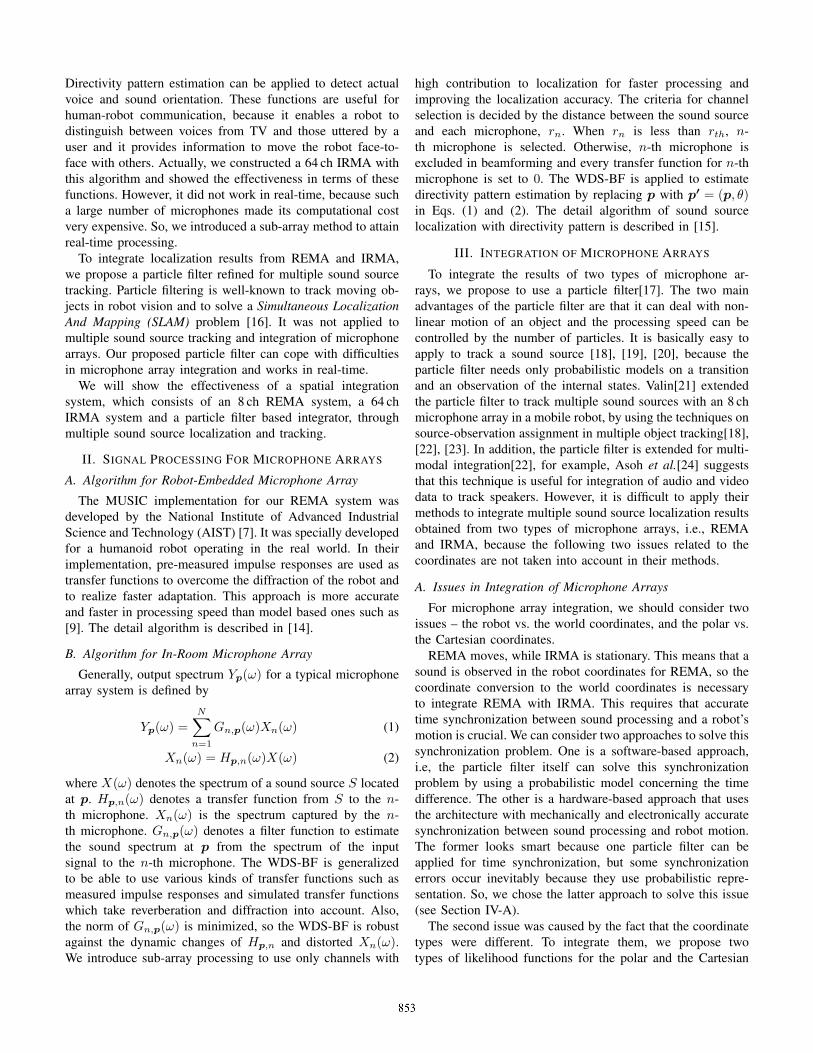
Directivity pattern estimation can be applied to detect actualvoice and sound orientation. These functions are useful forhuman-robot communication, because it enables a robot todistinguish between voices from TV and those uttered by auser and it provides information to move the robot face-to-face with others. Actually, we constructed a 64 ch IRMA withthis algorithm and showed the effectiveness in terms of thesefunctions. However, it did not work in real-time, because sucha large number of microphones made its computational costvery expensive. So, we introduced a sub-array method to attainreal-time processing.
To integrate localization results from REMA and IRMA,we propose a particle filter refined for multiple sound sourcetracking. Particle filtering is well-known to track moving ob-jects in robot vision and to solve a Simultaneous LocalizationAnd Mapping (SLAM) problem [16]. It was not applied tomultiple sound source tracking and integration of microphonearrays. Our proposed particle filter can cope with difficultiesin microphone array integration and works in real-time.
We will show the effectiveness of a spatial integrationsystem, which consists of an 8 ch REMA system, a 64 chIRMA system and a particle filter based integrator, throughmultiple sound source localization and tracking.
II. SIGNAL PROCESSING FOR MICROPHONE ARRAYS
A. Algorithm for Robot-Embedded Microphone Array
The MUSIC implementation for our REMA system wasdeveloped by the National Institute of Advanced IndustrialScience and Technology (AIST) [7]. It was specially developedfor a humanoid robot operating in the real world. In theirimplementation, pre-measured impulse responses are used astransfer functions to overcome the diffraction of the robot andto realize faster adaptation. This approach is more accurateand faster in processing speed than model based ones such as[9]. The detail algorithm is described in [14].
B. Algorithm for In-Room Microphone Array
Generally, output spectrum Yp(ω) for a typical microphonearray system is defined by
Yp(ω) =N∑
n=1
Gn,p(ω)Xn(ω) (1)
Xn(ω) = Hp,n(ω)X(ω) (2)
where X(ω) denotes the spectrum of a sound source S locatedat p. Hp,n(ω) denotes a transfer function from S to the n-th microphone. Xn(ω) is the spectrum captured by the n-th microphone. Gn,p(ω) denotes a filter function to estimatethe sound spectrum at p from the spectrum of the inputsignal to the n-th microphone. The WDS-BF is generalizedto be able to use various kinds of transfer functions such asmeasured impulse responses and simulated transfer functionswhich take reverberation and diffraction into account. Also,the norm of Gn,p(ω) is minimized, so the WDS-BF is robustagainst the dynamic changes of Hp,n and distorted Xn(ω).We introduce sub-array processing to use only channels with
high contribution to localization for faster processing andimproving the localization accuracy. The criteria for channelselection is decided by the distance between the sound sourceand each microphone, rn. When rn is less than rth, n-th microphone is selected. Otherwise, n-th microphone isexcluded in beamforming and every transfer function for n-thmicrophone is set to 0. The WDS-BF is applied to estimatedirectivity pattern estimation by replacing p with p′ = (p, θ)in Eqs. (1) and (2). The detail algorithm of sound sourcelocalization with directivity pattern is described in [15].
III. INTEGRATION OF MICROPHONE ARRAYS
To integrate the results of two types of microphone ar-rays, we propose to use a particle filter[17]. The two mainadvantages of the particle filter are that it can deal with non-linear motion of an object and the processing speed can becontrolled by the number of particles. It is basically easy toapply to track a sound source [18], [19], [20], because theparticle filter needs only probabilistic models on a transitionand an observation of the internal states. Valin[21] extendedthe particle filter to track multiple sound sources with an 8 chmicrophone array in a mobile robot, by using the techniques onsource-observation assignment in multiple object tracking[18],[22], [23]. In addition, the particle filter is extended for multi-modal integration[22], for example, Asoh et al.[24] suggeststhat this technique is useful for integration of audio and videodata to track speakers. However, it is difficult to apply theirmethods to integrate multiple sound source localization resultsobtained from two types of microphone arrays, i.e., REMAand IRMA, because the following two issues related to thecoordinates are not taken into account in their methods.
A. Issues in Integration of Microphone Arrays
For microphone array integration, we should consider twoissues – the robot vs. the world coordinates, and the polar vs.the Cartesian coordinates.
REMA moves, while IRMA is stationary. This means that asound is observed in the robot coordinates for REMA, so thecoordinate conversion to the world coordinates is necessaryto integrate REMA with IRMA. This requires that accuratetime synchronization between sound processing and a robot’smotion is crucial. We can consider two approaches to solve thissynchronization problem. One is a software-based approach,i.e, the particle filter itself can solve this synchronizationproblem by using a probabilistic model concerning the timedifference. The other is a hardware-based approach that usesthe architecture with mechanically and electronically accuratesynchronization between sound processing and robot motion.The former looks smart because one particle filter can beapplied for time synchronization, but some synchronizationerrors occur inevitably because they use probabilistic repre-sentation. So, we chose the latter approach to solve this issue(see Section IV-A).
The second issue was caused by the fact that the coordinatetypes were different. To integrate them, we propose twotypes of likelihood functions for the polar and the Cartesian

coordinates. These functions output likelihood independentfrom the coordinates. So, the two likelihood values can beeasily integrated. The detail is explained below.
B. Particle Filter
In the particle filter, the transition model p(x(t)|x(t − 1))and the observation model p(y(t)|x(t)) of internal state x(t)are defined as probabilistic representation. y(t) denotes anobservation vector. Because the particle filter allows a non-linear transition model, it is more flexible than other linearfiltering methods such as the Kalman filter. A particle playsa role of an agent to track a target source. The i-th particleincludes the internal states xi(t) and the importance weightwi(t), which is an index to show how the particle contributesto tracking and is usually defined as likelihood. The densityof a set of the particles approximates posterior probabilityp(x(t)|y(t)). In other words, the posterior probability issampled by the particles. That is why the particle filter isalso called a sampling method. In our case, two types ofobservations, Y REMA(t) and Y IRMA(t), are obtained fromthe microphone arrays at time t.
Y REMA(t) = {ya1(t), · · · ,yal
(t), · · · ,yaLt(t)}, (3)
Y IRMA(t) = {yb1(t), · · · ,ybm(t), · · · ,ybMt
(t)} (4)
where Lt and Mt are the number of observations by REMAand IRMA at time t. yal
and ybmare denoted as
yal= {aθl
, apl}, (5)
ybm= {bxm
, bym, bom
, bpm}, (6)
where aθlis the azimuth in the world coordinates. bxm
andbym
are the position in the world coordinates, and bomis the
orientation of a sound source. apland bpm
are the estimatedpower in dB.
Our particle filter consists of the following five steps:Initialization, Source check, Importance sampling, Selection,and Output. The following sections describe each step indetail.
Step 1 – Initialization: This step makes the initial states of aparticle. We defined (xi(t), yi(t), vi(t), oi(t)) as the internalstates of i-th particle. (xi(t), yi(t)) denotes the position ofa sound source. vi(t) and oi(t) are the velocity and theorientation of the sound source. At the initial state, the particleswere distributed uniformly at random. To deal with multiplesound sources, we initialized the importance weight definedby
∑i∈Pk
wi = 1,
S∑k=1
Nk = N, (7)
where Nk is the number of particles for k-th particle groupPk, and S is the number of sound sources. N is the fixedvalue which shows the total number of particles.
Step 2 – Source Check: This step is newly added to supportmultiple sound sources. The internal state of the particle groupPk is defined by
xk(t) =∑i∈Pk
xi(t) · wi(t) (8)
When ym(t) satisfies ||xk(t) − ym(t)|| < Dth, ym(t)is associated with Pk. When no particle group is found forym(t), a new particle group is generated. When no observationis found for the particle group Pk for more than time Tth, Pk
is terminated. In both cases, the particles are re-distributed sothat Eq. (7) is maintained.
Step 3 – Importance Sampling: In this step, first, xi(t)is estimated from xi(t − 1) by using the transition modelp(x(t)|x(t − 1)). Secondly, wi(t) is updated by Eq. (20).Finally, wi(t) is normalized subject to Eq. (7).
For the transition model, we switched two models based onrandom walk and Newton’s equation of motion according tothe velocity of the sound source. When the velocity is lessthan vth, which is empirically set to 2m/s, the system usesthe transition model based on random walk defined by
xi(t) = xi(t − 1) + rx, (9)yi(t) = yi(t − 1) + ry, (10)vi(t) = vi(t − 1) + rv, (11)oi(t) = oi(t − 1) + ro, (12)
where r∗ denotes white noise.When the velocity is larger than vth, the system uses
the transition model based on Newton’s equation of motiondefined by
xi(t) = xi(t − 1) (13)+ vi(t − 1) · cos(oi(t − 1)) + rx,
yi(t) = yi(t − 1) (14)+ vi(t − 1) · sin(oi(t − 1)) + ry,
vi(t) = α · vi(t − 1) (15)
+ (1 − α) ·√
Δxi(t)2 + Δyi(t)2 + rv,
oi(t) = αoi(t − 1) (16)
+ (1 − α) · tan−1
(Δyi(t)Δxi(t)
)+ rθ,
where α is an weight defined experimentally. Δxi(t) andΔyi(t) are defined by
Δxi(t) = xi(t) − xi(t − 1),Δyi(t) = yi(t) − yi(t − 1).
The likelihood is defined as follows:
lREMA(t) = exp
(− (� (xi(t) − P REMA(t)) − θl)
2
2RREMA
)(17)
lIRMA(t) = exp
(−||xi(t) − ybm
(t)||22RIRMA
)(18)
where � (x) denotes the angular coordinate for x. RREMA
and RIRMA are variances of localization results by REMA

IRMA
system
REMA
system
Microphone Array Integrator
micophone array
mic
opho
ne a
rray m
icophone array
Sound Viewer
tracking results
localizationresults
localizationresults
robot
Fig. 1. Spatial Integration System
and IRMA, P REMA is the position of the robot. They areintegrated into lI(t).
lI(t) = αl · lREMA(t) + (1 − αl) · lIRMA(t) (19)
where αl is an integration weight value. Finally wi is updatedby
wi(t) = lI(t) · wi(t − 1). (20)
Step 4 – Selection: According to the importance weightwi, the selection step propagates and removes particles. Wheni ∈ Pk, the number of particles for i is updated by
Nki= round(Nk · wi). (21)
In this case, some particles can remain. The number of suchparticles is calculated by
Rk = Nk −∑i∈Pk
Nki. (22)
These particles are also distributed according to the residueweight Rwi
.Rwi
= wi − Nki/∑i∈Pk
Nki(23)
For this, Sampling Importance Resampling (SIR) algorithm[17] is commonly used.
Step 5 – Output: From the density of the updated particles,the posterior probability is estimated as p(x(t)|ym(t)). Theinternal states of a set of particles for sound source k isestimated as Eq. (8). Steps 2 – 5 are repeated until the trackingprocess finishes.
IV. SYSTEM IMPLEMENTATION
Fig 1 shows the architecture of our spatial integrationsystem. It consists of four components – a robot with a REMAsystem, an IRMA system, a microphone array integrator anda sound viewer. They are described in the following sections.
A. Robot with REMA System
For the REMA system, we developed a wheel-based robotshown in Fig. 2. The robot consists of the head of HondaASIMO, a rotational table, an omni-directional vehicle and an8 ch REMA system. The rotational table is controlled by aremote PC via an I/O card shown in Fig. 3. The angle of rota-tion is measured by an encoder accurately. Its resolution of theangle measurement is 0.0015◦. The omni-directional vehiclealso can be controlled by a remote PC via a wireless-LAN. Themaximum load of the vehicle is 80 kg. The side of the vehicleis covered by sensors to detect collision. The REMA system
omni-directionalvehicle
rotational table
robot-embeddedmicrophone array
ASIMO head
Fig. 2. Wheel-based Robot
Robot Microphone
Array
Rotational Table
Encoder
Potentio-meter
Voltage-FrequencyConverter
multi-channelsound card
I/O card
PC
motion command
digitalized angle data
frequency modulatedangle data
sound data
angle data
Fig. 3. The Architecture of REMA
consists of 8 microphones, and each microphone is embeddedin a rubber head-band at the same interval. The head-band isinstalled on the head of ASIMO.
The captured sound signals by REMA and the signals ofangle information from the encoder are sent to one PC. Tolocalize sound signals in the world coordinates even whenthe robot is in rotation, these two types of signals should besynchronized precisely. The encoder outputs accurate informa-tion, but it takes small processing time to send the digitizeddata. This makes time difference between the captured soundsignals and the corresponding encoder output signal. To makeprecise synchronization, we measured the time difference.As shown in Fig. 3, we installed a potentio-meter in therotational table to detect rotation quickly in addition to theencoder. The potentio-meter was connected to the sound cardto synchronously capture sounds from REMA via a voltage-frequency converter which prevents a DC component likepotentio-meter output from being filtered out by the soundcard. Because the potentio-meter produced analog output, theoutput included larger errors (0.95◦), but the time differencewas regarded as 0, since the data was captured with soundsfrom REMA simultaneously. Therefore, we measured the timedifference by comparing angle data captured by the sound cardwith that sent from the encoder. As a result, we found that theangle data from the encoder was delayed 32.9 ms on averagein comparison with captured sound signals. This delay wastaken into account in the coordinate conversion from the robotcoordinates to the world coordinates.
B. IRMA System
We constructed a 64 ch IRMA system. The IRMA capturesan acoustic signal from 64 microphones synchronously at asampling rate of 16 kHz using four RASP II. Fig. 4 depicts a4.0 m × 7.0 m room for IRMA. It is acoustically asymmetricalbecause three walls are covered with sound absorbing material,another wall is made of glass with high sound reflection, andthere is a kitchen sink. The asterisks represent microphonepositions in the room. The height of the microphones on thewall is 1.2 m. This microphone layout was decided because itcovers as much of the room as possible. The sound positionwas digitized at an interval of 25 cm. The digitizing areawas 1.0 m – 5.0 m for X axis, and 0.5 m – 3.5 m for Yaxis. The height (Z axis) was fixed to 1.2 m. So, the numberof pm is 221. To design a beamformer for IRMA, we cal-culated beamforming coefficients from pre-measured transfer
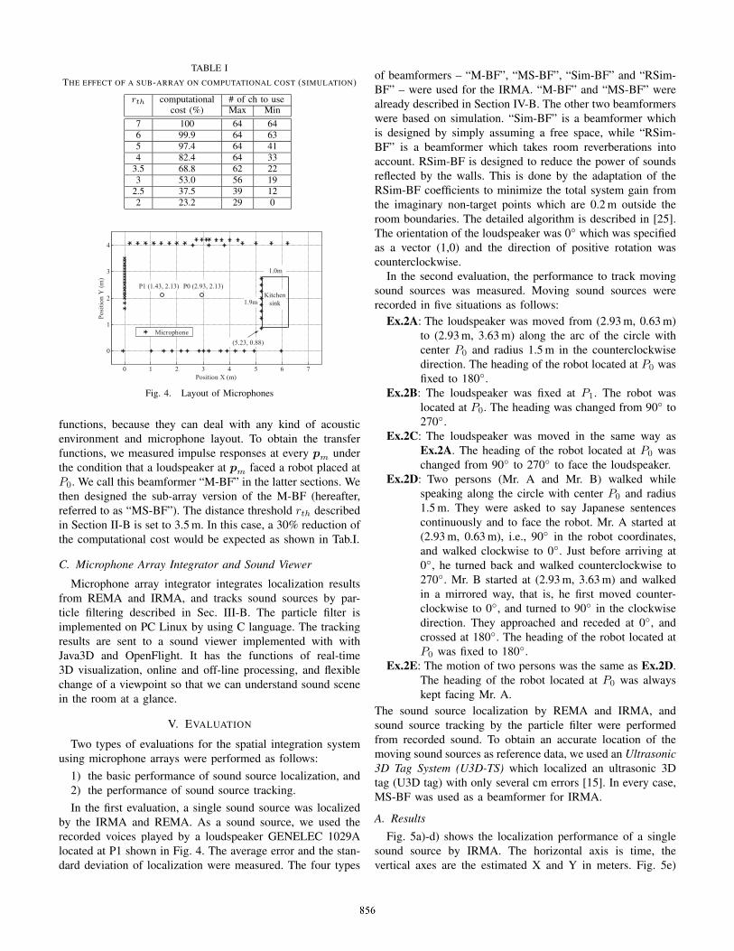
TABLE ITHE EFFECT OF A SUB-ARRAY ON COMPUTATIONAL COST (SIMULATION)
rth computational # of ch to usecost (%) Max Min
7 100 64 646 99.9 64 635 97.4 64 414 82.4 64 33
3.5 68.8 62 223 53.0 56 19
2.5 37.5 39 122 23.2 29 0
0 1 2 3 4 5 6 7
0
1
2
3
4
Position X (m)
Pos
itio
n Y
(m
)
Microphone
P1 (1.43, 2.13) P0 (2.93, 2.13)Kitchen
sink
(5.23, 0.88)
1.9m
1.0m
Fig. 4. Layout of Microphones
functions, because they can deal with any kind of acousticenvironment and microphone layout. To obtain the transferfunctions, we measured impulse responses at every pm underthe condition that a loudspeaker at pm faced a robot placed atP0. We call this beamformer “M-BF” in the latter sections. Wethen designed the sub-array version of the M-BF (hereafter,referred to as “MS-BF”). The distance threshold rth describedin Section II-B is set to 3.5 m. In this case, a 30% reduction ofthe computational cost would be expected as shown in Tab.I.
C. Microphone Array Integrator and Sound Viewer
Microphone array integrator integrates localization resultsfrom REMA and IRMA, and tracks sound sources by par-ticle filtering described in Sec. III-B. The particle filter isimplemented on PC Linux by using C language. The trackingresults are sent to a sound viewer implemented with withJava3D and OpenFlight. It has the functions of real-time3D visualization, online and off-line processing, and flexiblechange of a viewpoint so that we can understand sound scenein the room at a glance.
V. EVALUATION
Two types of evaluations for the spatial integration systemusing microphone arrays were performed as follows:
1) the basic performance of sound source localization, and2) the performance of sound source tracking.In the first evaluation, a single sound source was localized
by the IRMA and REMA. As a sound source, we used therecorded voices played by a loudspeaker GENELEC 1029Alocated at P1 shown in Fig. 4. The average error and the stan-dard deviation of localization were measured. The four types
of beamformers – “M-BF”, “MS-BF”, “Sim-BF” and “RSim-BF” – were used for the IRMA. “M-BF” and “MS-BF” werealready described in Section IV-B. The other two beamformerswere based on simulation. “Sim-BF” is a beamformer whichis designed by simply assuming a free space, while “RSim-BF” is a beamformer which takes room reverberations intoaccount. RSim-BF is designed to reduce the power of soundsreflected by the walls. This is done by the adaptation of theRSim-BF coefficients to minimize the total system gain fromthe imaginary non-target points which are 0.2 m outside theroom boundaries. The detailed algorithm is described in [25].The orientation of the loudspeaker was 0◦ which was specifiedas a vector (1,0) and the direction of positive rotation wascounterclockwise.
In the second evaluation, the performance to track movingsound sources was measured. Moving sound sources wererecorded in five situations as follows:
Ex.2A: The loudspeaker was moved from (2.93 m, 0.63 m)to (2.93 m, 3.63 m) along the arc of the circle withcenter P0 and radius 1.5 m in the counterclockwisedirection. The heading of the robot located at P0 wasfixed to 180◦.
Ex.2B: The loudspeaker was fixed at P1. The robot waslocated at P0. The heading was changed from 90◦ to270◦.
Ex.2C: The loudspeaker was moved in the same way asEx.2A. The heading of the robot located at P0 waschanged from 90◦ to 270◦ to face the loudspeaker.
Ex.2D: Two persons (Mr. A and Mr. B) walked whilespeaking along the circle with center P0 and radius1.5 m. They were asked to say Japanese sentencescontinuously and to face the robot. Mr. A started at(2.93 m, 0.63 m), i.e., 90◦ in the robot coordinates,and walked clockwise to 0◦. Just before arriving at0◦, he turned back and walked counterclockwise to270◦. Mr. B started at (2.93 m, 3.63 m) and walkedin a mirrored way, that is, he first moved counter-clockwise to 0◦, and turned to 90◦ in the clockwisedirection. They approached and receded at 0◦, andcrossed at 180◦. The heading of the robot located atP0 was fixed to 180◦.
Ex.2E: The motion of two persons was the same as Ex.2D.The heading of the robot located at P0 was alwayskept facing Mr. A.
The sound source localization by REMA and IRMA, andsound source tracking by the particle filter were performedfrom recorded sound. To obtain an accurate location of themoving sound sources as reference data, we used an Ultrasonic3D Tag System (U3D-TS) which localized an ultrasonic 3Dtag (U3D tag) with only several cm errors [15]. In every case,MS-BF was used as a beamformer for IRMA.
A. Results
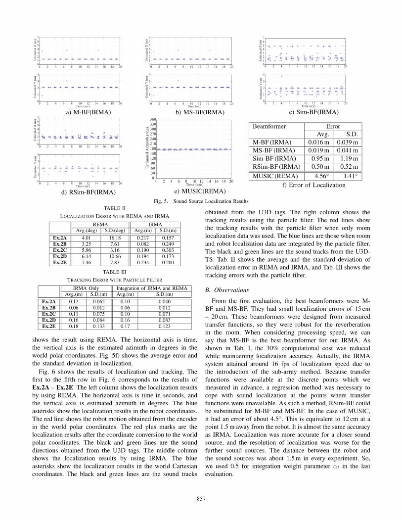
Fig. 5a)-d) shows the localization performance of a singlesound source by IRMA. The horizontal axis is time, thevertical axes are the estimated X and Y in meters. Fig. 5e)
0 2 4 6 8 10 12 14 16 18 2001234567
Est
imat
ed X
(m
)
0 2 4 6 8 10 12 14 16 18 200
1
2
3
4
Est
imat
ed Y
(m
)
Time (sec)
a) M-BF(IRMA)
0 2 4 6 8 10 12 14 16 18 2001234567
Est
imat
ed X
(m
)
0 2 4 6 8 10 12 14 16 18 200
1
2
3
4
Est
imat
ed Y
(m
)
Time (sec)
b) MS-BF(IRMA)
0 2 4 6 8 10 12 14 16 18 2001234567
Est
imat
ed X
(m
)
0 2 4 6 8 10 12 14 16 18 200
1
2
3
4
Est
imat
ed Y
(m
)
Time (sec)
c) Sim-BF(IRMA)
0 2 4 6 8 10 12 14 16 18 2001234567
Est
imat
ed X
(m
)
0 2 4 6 8 10 12 14 16 18 200
1
2
3
4
Est
imat
ed Y
(m
)
Time (sec)
d) RSim-BF(IRMA)
0 2 4 6 8 10 12 14 16 18 200
306090
120150180210240270300330360
Time (sec)
Est
imat
ed A
zim
uth
(deg
)
e) MUSIC(REMA)
Beamformer ErrorAvg. S.D.
M-BF (IRMA) 0.016 m 0.039 mMS-BF (IRMA) 0.019 m 0.041 mSim-BF (IRMA) 0.95 m 1.19 mRSim-BF (IRMA) 0.50 m 0.52 mMUSIC (REMA) 4.56◦ 1.41◦
f) Error of Localization
Fig. 5. Sound Source Localization ResultsTABLE II
LOCALIZATION ERROR WITH REMA AND IRMA
REMA IRMAAvg.(deg) S.D.(deg) Avg.(m) S.D.(m)
Ex.2A 4.01 16.18 0.217 0.157Ex.2B 3.25 7.61 0.082 0.249Ex.2C 5.96 3.16 0.190 0.303Ex.2D 6.14 10.66 0.194 0.173Ex.2E 7.46 7.83 0.234 0.200
TABLE IIITRACKING ERROR WITH PARTICLE FILTER
IRMA Only Integration of IRMA and REMAAvg.(m) S.D.(m) Avg.(m) S.D.(m)
Ex.2A 0.12 0.062 0.10 0.040Ex.2B 0.06 0.012 0.06 0.012Ex.2C 0.11 0.075 0.10 0.071Ex.2D 0.16 0.084 0.16 0.083Ex.2E 0.18 0.133 0.17 0.123
shows the result using REMA. The horizontal axis is time,the vertical axis is the estimated azimuth in degrees in theworld polar coordinates. Fig. 5f) shows the average error andthe standard deviation in localization.
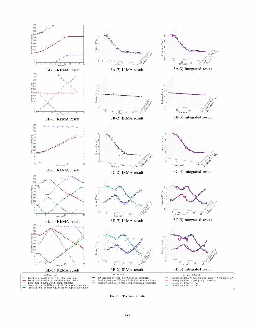
Fig. 6 shows the results of localization and tracking. Thefirst to the fifth row in Fig. 6 corresponds to the results ofEx.2A – Ex.2E. The left column shows the localization resultsby using REMA. The horizontal axis is time in seconds, andthe vertical axis is estimated azimuth in degrees. The blueasterisks show the localization results in the robot coordinates.The red line shows the robot motion obtained from the encoderin the world polar coordinates. The red plus marks are thelocalization results after the coordinate conversion to the worldpolar coordinates. The black and green lines are the sounddirections obtained from the U3D tags. The middle columnshows the localization results by using IRMA. The blueasterisks show the localization results in the world Cartesiancoordinates. The black and green lines are the sound tracks
obtained from the U3D tags. The right column shows thetracking results using the particle filter. The red lines showthe tracking results with the particle filter when only roomlocalization data was used. The blue lines are those when roomand robot localization data are integrated by the particle filter.The black and green lines are the sound tracks from the U3D-TS. Tab. II shows the average and the standard deviation oflocalization error in REMA and IRMA, and Tab. III shows thetracking errors with the particle filter.
B. Observations
From the first evaluation, the best beamformers were M-BF and MS-BF. They had small localization errors of 15 cm– 20 cm. These beamformers were designed from measuredtransfer functions, so they were robust for the reverberationin the room. When considering processing speed, we cansay that MS-BF is the best beamformer for our IRMA. Asshown in Tab. I, the 30% computational cost was reducedwhile maintaining localization accuracy. Actually, the IRMAsystem attained around 16 fps of localization speed due tothe introduction of the sub-array method. Because transferfunctions were available at the discrete points which wemeasured in advance, a regression method was necessary tocope with sound localization at the points where transferfunctions were unavailable. As such a method, RSim-BF couldbe substituted for M-BF and MS-BF. In the case of MUSIC,it had an error of about 4.5◦. This is equivalent to 12 cm at apoint 1.5 m away from the robot. It is almost the same accuracyas IRMA. Localization was more accurate for a closer soundsource, and the resolution of localization was worse for thefurther sound sources. The distance between the robot andthe sound sources was about 1.5 m in every experiment. So,we used 0.5 for integration weight parameter αl in the lastevaluation.
0 2 4 6 8 10 12 14 16 18 200
30
60
90
120
150
180
210
240
270
300
330
360
Time (sec)
Est
imat
ed A
zim
uth
(deg
)
3A-1) REMA result
0 2 4 6 8 10 12 14 16 18 20 0 1
2
3 4
5
6 7
0 1 2 3 4
Estim
ated
X (m
)
Time (sec)
Est
imat
ed Y
(m
)
3A-2) IRMA result
0 5 10 15 20 0 1
2 3
4 5
6 7
0
1
2
3
4
Estim
ated
X (m
)
Time (sec)
Est
imat
ed Y
(m)
3A-3) integrated result
0 5 10 15 20 25 300
30
60
90
120
150
180
210
240
270
300
330
360
Time (sec)
Est
imat
ed A
zim
uth
(deg
)
3B-1) REMA result
0 5 10 15 20 25 30 0 1 2 3 4 5 6 7
0 1 2 3 4
Estim
ated
X (m
)
Time (sec)
Est
imat
ed Y
(m
)
3B-2) IRMA result
0 10 20 30 0 1 2 3 4 5 6 7
0
1
2
3
4
Estim
ated
X( m
)
Time (sec)
Est
imat
ed Y
(m
)
3B-3) integrated result
0 5 10 150
30
60
90
120
150
180
210
240
270
300
330
360
Time (sec)
Est
imat
ed A
zim
uth
(deg
)
3C-1) REMA result
05
1015 0
1 2
3
4 5
6
7
0 1 2 3 4
Estimate
d X (m
)
Time (sec)
Est
imat
ed Y
(m
)
3C-2) IRMA result
0 5 10 15 0 1
2 3
4 5
6 7
0 1 2 3 4
Estim
ated X
(m)
Time (sec)E
stim
ated
Y (m
)
3C-3) integrated result
0 5 10 15 20 250
30
60
90
120
150
180
210
240
270
300
330
360
Time (sec)
Est
imat
ed A
zim
uth
(deg
)
3D-1) REMA result
0 5 10 15 20 25 0 1
2
3 4
5
6 7
0 1 2 3 4
Estim
ated
X (m
)
Time (sec)
Est
imat
ed Y
(m
)
3D-2) IRMA result
0 5 10 15 20 25 0 1 2 3 4 5 6 7
0
1
2
3
4
Estim
ated
X (m
)Time (sec)
Est
imat
ed Y
(m
)
3D-3) integrated result
0 5 10 15 20 250
30
60
90
120
150
180
210
240
270
300
330
360
Time (sec)
Est
imat
ed A
zim
uth
(deg
)
3E-1) REMA result
0 5 10 15 20 25 0 1 2 3 4 5 6 7
0 1 2 3 4
Estim
ated
X (m
)
Time (sec)
Est
imat
ed Y
(m
)
3E-2) IRMA result
0 5 10 15 20 250
12
34
56
7
0
1
2
3
4
Estim
ated
X (m
)
Time (sec)
Est
imat
ed Y
(m
)
3E-3) integrated result
******++++++
Localization result in the robot polar coordinatesLocalization result in the world polar coordinatesRobot motion in the world polar coordinatesTracking result by U3D tag 1 in the world polar coordinatesTracking result by U3D tag 2 in the world polar coordinates
****** 2D Localization result in the Cartesian coordinatesTracking result by U3D tag 1 in the Cartesian coordinatesTracking result by U3D tag 2 in the Cartesian coordinates
REMA result IRMA resultTracking result by PF (integration of room-MA and robot-MA)Tracking result by PF (using only room-MA)Tracking result by U3D tag 1Tracking result by U3D tag 2
Integrated Result
Fig. 6. Tracking Results
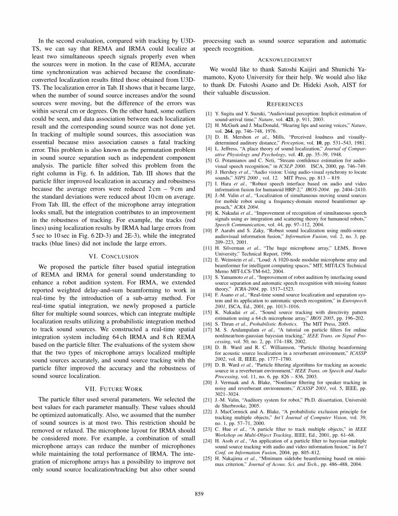
In the second evaluation, compared with tracking by U3D-TS, we can say that REMA and IRMA could localize atleast two simultaneous speech signals properly even whenthe sources were in motion. In the case of REMA, accuratetime synchronization was achieved because the coordinate-converted localization results fitted those obtained from U3D-TS. The localization error in Tab. II shows that it became large,when the number of sound source increases and/or the soundsources were moving, but the difference of the errors waswithin several cm or degrees. On the other hand, some outlierscould be seen, and data association between each localizationresult and the corresponding sound source was not done yet.In tracking of multiple sound sources, this association wasessential because miss association causes a fatal trackingerror. This problem is also known as the permutation problemin sound source separation such as independent componentanalysis. The particle filter solved this problem from theright column in Fig. 6. In addition, Tab. III shows that theparticle filter improved localization in accuracy and robustnessbecause the average errors were reduced 2 cm – 9 cm andthe standard deviations were reduced about 10 cm on average.From Tab. III, the effect of the microphone array integrationlooks small, but the integration contributes to an improvementin the robustness of tracking. For example, the tracks (redlines) using localization results by IRMA had large errors from5 sec to 10 sec in Fig. 6 2D-3) and 2E-3), while the integratedtracks (blue lines) did not include the large errors.
VI. CONCLUSION
We proposed the particle filter based spatial integrationof REMA and IRMA for general sound understanding toenhance a robot audition system. For IRMA, we extendedreported weighted delay-and-sum beamforming to work inreal-time by the introduction of a sub-array method. Forreal-time spatial integration, we newly proposed a particlefilter for multiple sound sources, which can integrate multiplelocalization results utilizing a probabilistic integration methodto track sound sources. We constructed a real-time spatialintegration system including 64 ch IRMA and 8 ch REMAbased on the particle filter. The evaluations of the system showthat the two types of microphone arrays localized multiplesound sources accurately, and sound source tracking with theparticle filter improved the accuracy and the robustness ofsound source localization.
VII. FUTURE WORK
The particle filter used several parameters. We selected thebest values for each parameter manually. These values shouldbe optimized automatically. Also, we assumed that the numberof sound sources is at most two. This restriction should beremoved or relaxed. The microphone layout for IRMA shouldbe considered more. For example, a combination of smallmicrophone arrays can reduce the number of microphoneswhile maintaining the total performance of IRMA. The inte-gration of microphone arrays has a possibility to improve notonly sound source localization/tracking but also other sound
processing such as sound source separation and automaticspeech recognition.
ACKNOWLEDGEMENT
We would like to thank Satoshi Kaijiri and Shunichi Ya-mamoto, Kyoto University for their help. We would also liketo thank Dr. Futoshi Asano and Dr. Hideki Asoh, AIST fortheir valuable discussion.
REFERENCES
[1] Y. Sugita and Y. Suzuki, “Audiovisual perception: Implicit estimation ofsound-arrival time,” Nature, vol. 421, p. 911, 2003.
[2] H. McGurk and J. MacDonald, “Hearing lips and seeing voices,” Nature,vol. 264, pp. 746–748, 1976.
[3] D. H. Mershon et al., Mills, “Perceived loudness and visually-determined auditory distance,” Perception, vol. 10, pp. 531–543, 1981.
[4] L. Jeffress, “A place theory of sound localization,” Journal of Compar-ative Physiology and Psychology, vol. 41, pp. 35–39, 1948.
[5] G. Potamianos and C. Neti, “Stream confidence estimation for audio-visual speech recognition,” in ICSLP 2000. ISCA, 2000, pp. 746–749.
[6] J. Hershey et al., “Audio vision: Using audio-visual synchrony to locatesounds,” NIPS 2000 , vol. 12. MIT Press, pp. 813 – 819.
[7] I. Hara et al., “Robust speech interface based on audio and videoinformation fusion for humanoid HRP-2,” IROS-2004. pp. 2404–2410.
[8] J.-M. Valin et al., “Localization of simultaneous moving sound sourcesfor mobile robot using a frequency-domain steered beamformer ap-proach,” ICRA 2004.
[9] K. Nakadai et al., “Improvement of recognition of simultaneous speechsignals using av integration and scattering theory for humanoid robots,”Speech Communication, vol. 44, pp. 97–112, 2004.
[10] P. Aarabi and S. Zaky, “Robust sound localization using multi-sourceaudiovisual information fusion,” Information Fusion, vol. 2, no. 3, pp.209–223, 2001.
[11] H. Silverman et al., “The huge microphone array,” LEMS, BrownUniversity,” Technical Report, 1996.
[12] E. Weinstein et al., “Loud: A 1020-node modular microphone array andbeamformer for intelligent computing spaces,” MIT, MIT/LCS TechnicalMemo MIT-LCS-TM-642, 2004.
[13] S. Yamamoto et al., “Improvement of robot audition by interfacing soundsource separation and automatic speech recognition with missing featuretheory,” ICRA-2004, pp. 1517–1523.
[14] F. Asano et al., “Real-time sound source localization and separation sys-tem and its application to automatic speech recognition,” in Eurospeech2001, ISCA, Ed., 2001, pp. 1013–1016.
[15] K. Nakadai et al., “Sound source tracking with directivity patternestimation using a 64 ch microphone array,” IROS 2005, pp. 196–202.
[16] S. Thrun et al., Probabilistic Robotics. The MIT Press, 2005.[17] M. S. Arulampalam et al., “A tutorial on particle filters for online
nonlinear/non-gaussian bayesian tracking,” IEEE Trans. on Signal Pro-cessing, vol. 50, no. 2, pp. 174–188, 2002.
[18] D. B. Ward and R. C. Williamson, “Particle filtering beamformingfor acoustic source localization in a reverberant environment,” ICASSP2002, vol. II, IEEE, pp. 1777–1780.
[19] D. B. Ward et al., “Particle filtering algorithms for tracking an acousticsource in a reverberant environment,” IEEE Trans. on Speech and AudioProcessing, vol. 11, no. 6, pp. 826 – 836, 2003.
[20] J. Vermaak and A. Blake, “Nonlinear filtering for speaker tracking innoisy and reverberant environments,” ICASSP 2001, vol. 5, IEEE, pp.3021–3024.
[21] J.-M. Valin, “Auditory system for robot,” Ph.D. dissertation, Universitede Sherbrooke, 2005.
[22] J. MacCormick and A. Blake, “A probabilistic exclusion principle fortracking multiple objects,” Int’l Journal of Computer Vision, vol. 39,no. 1, pp. 57–71, 2000.
[23] C. Hue et al., “A particle filter to track multiple objects,” in IEEEWorkshop on Multi-Object Tracking, IEEE, Ed., 2001, pp. 61–68.
[24] H. Asoh et al., “An application of a particle filter to bayesian multiplesound source tracking with audio and video information fusion,” in Int’lConf. on Information Fusion, 2004, pp. 805–812.
[25] H. Nakajima et al., “Minimum sidelobe beamforming based on mini-max criterion,” Journal of Acous. Sci. and Tech., pp. 486–488, 2004.