Real-Time Rendering (Echtzeitgraphik)
77
Transcript of Real-Time Rendering (Echtzeitgraphik)

Shading and Lighting Effects

Overview
Environment mapping
Cube mapping
Sphere mapping
Dual-paraboloid mapping
Reflections, Refractions, Speculars, Diffuse (Irradiance) mapping
Normal mapping
Parallax normal mapping
Advanced Methods
Vienna University of Technology 3

Environment Mapping
Main idea: fake reflections using simple textures
Vienna University of Technology 4

Environment Mapping Assumption: index envmap via orientation
Reflection vector or any other similar lookup!
Ignore (reflection) position! True if: reflecting object shrunk to a single point OR: environment infinitely far away
Eye not very good at discovering the fake
Vienna University of Technology 5
Environment Map
Viewpoint

Environment Mapping
Can be an “Effect”
Usually means: “fake reflection”
Can be a “Technique” (i.e., GPU feature)
Then it means: “2D texture indexed by a 3D orientation”
Usually the index vector is the reflection vector
But can be anything else that’s suitable!
Vienna University of Technology 6
Environment Mapping
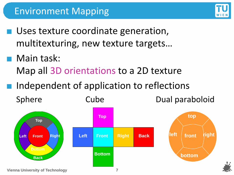
Uses texture coordinate generation, multitexturing, new texture targets…
Main task: Map all 3D orientations to a 2D texture
Independent of application to reflections
Sphere Cube Dual paraboloid
Vienna University of Technology 7
Left
Top
Bottom
Right Back Front
Back
Top
Front Right
Bottom
Left front
top
bottom
left right

Cube Mapping
OpenGL texture targets
Vienna University of Technology 8
Left
Top
Bottom
Right Back Front
glTexImage2D(
GL_TEXTURE_CUBE_MAP_POSITIVE_X, 0, GL_RGB8,
w, h, 0, GL_RGB, GL_UNSIGNED_BYTE, face_px);

Cube Mapping
Cube map accessed via vectors expressed as 3D texture coordinates (s, t, r)
Vienna University of Technology 9
+s
-r
+t

Cube Mapping
3D 2D projection done by hardware
Highest magnitude component selects which cube face to use (e.g., -t)
Divide other components by this, e.g.: s’ = s / -t r’ = r / -t
(s’, r’) is in the range [-1, 1]
remap to [0,1] and select a texel from selected face
Still need to generate useful texture coordinates for reflections
Vienna University of Technology 10

Cube Maps for Env Mapping
Generate views of the environment
One for each cube face
90° view frustum
Use hardware to render directly to a texture
Use reflection vector to index cube map
Generated automatically on hardware: glTexGeni(GL_S, GL_TEXTURE_GEN_MODE,
GL_REFLECTION_MAP);
Vienna University of Technology 11

Cube Map Coordinates
Warning: addressing not intuitive (needs flip)
Vienna University of Technology 12
Watt 3D CG Renderman/OpenGL

Cube Mapping
Advantages
Minimal distortions
Creation and map entirely hardware accelerated
Can be generated dynamically
Optimizations for dynamic scenes
Need not be updated every frame
Low resolution sufficient
Vienna University of Technology 13

Sphere Mapping
Earliest available method with OpenGL
Only texture mapping required!
Texture looks like orthographic reflection from chrome hemisphere
Can be photographed like this!
Vienna University of Technology 14
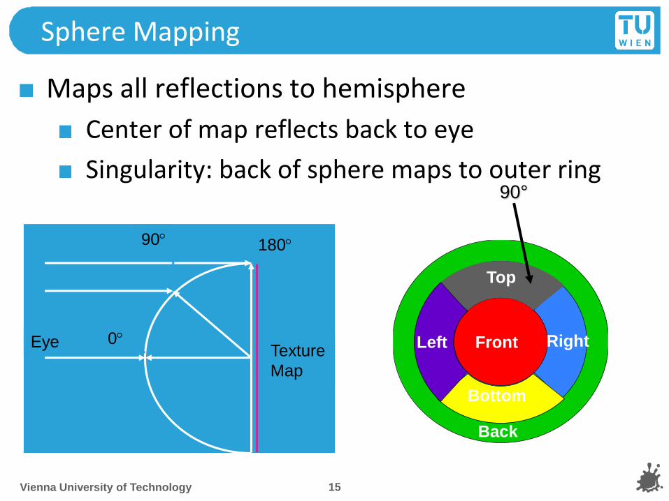
Sphere Mapping
Maps all reflections to hemisphere
Center of map reflects back to eye
Singularity: back of sphere maps to outer ring
Vienna University of Technology 15
0
90 180
Eye Texture
Map
Back
Top
Front Right
Bottom
Left
90°

Sphere Mapping
Texture coordinates generated automatically glTexGeni(GL_S, GL_TEXTURE_GEN_MODE,
GL_SPHERE_MAP);
Uses eye-space reflection vector (internally)
Generation Ray tracing
Warping a cube map (possible on the fly)
Take a photograph of a metallic sphere!!
Disadvantages:
View dependent has to be regenerated even for static environments!
Distortions
Vienna University of Technology 16

Vienna University of Technology 17

Dual Paraboloid Mapping
Use orthographic reflection of two parabolic mirrors instead of a sphere
Vienna University of Technology 18

Dual Paraboloid Mapping
Texture coordinate generation:
Generate reflection vector using OpenGL
Load texture matrix with P · M-1
M is inverse view matrix (view independency)
P is a projection which accomplishes s = rx / (1-rz) t = ry / (1-rz)
Texture access across seam:
Always apply both maps with multitexture
Use alpha to select active map for each pixel
Vienna University of Technology 19

Dual Paraboloid mapping
Advantages
View independent
Requires only projective texturing
Even less distortions than cube mapping
Disadvantages
Can only be generated using ray tracing or warping
No direct rendering like cube maps
No photographing like sphere maps
Vienna University of Technology 20

Summary Environment Mapping
Sphere Cube Paraboloid
View- dependent independent independent
Generation warp/ray/
photo
direct
rendering/
photo
warp/ray
Hardware
required
texture
mapping
cube map
support
projective
texturing, 2
texture units
Distortions strong medium little
Vienna University of Technology 21

Reflective Environment Mapping
Angle of incidence = angle of reflection
OpenGL uses eye coordinates for R
Cube map needs reflection vector in world coordinates (where map was created)
Load texture matrix with inverse 3x3 view matrix
Best done in fragment shader
Vienna University of Technology 22
N
R V R = V - 2 (N dot V) N
post-modelview view vector
V and N normalized!

Example Vertex Program (CG) void C7E1v_reflection(float4 position : POSITION,
float2 texCoord : TEXCOORD0,
float3 normal : NORMAL,
out float4 oPosition : POSITION,
out float2 oTexCoord : TEXCOORD0,
out float3 R : TEXCOORD1,
uniform float3 eyePositionW,
uniform float4x4 modelViewProj,
uniform float4x4 modelToWorld,
uniform float4x4 modelToWorldInverseTranspose)
{
oPosition = mul(modelViewProj, position);
oTexCoord = texCoord;
// Compute position and normal in world space
float3 positionW = mul(modelToWorld, position).xyz;
float3 N = mul((float3x3) modelToWorldInverseTranspose, normal);
N = normalize(N);
// Compute the incident and reflected vectors
float3 I = positionW - eyePositionW;
R = reflect(I, N);
}
Vienna University of Technology 23

Example Fragment Program
void C7E2f_reflection(float2 texCoord : TEXCOORD0,
float3 R : TEXCOORD1,
out float4 color : COLOR,
uniform float reflectivity,
uniform sampler2D decalMap,
uniform samplerCUBE environmentMap)
{
// Fetch reflected environment color
float4 reflectedColor = texCUBE(environmentMap, R);
// Fetch the decal base color
float4 decalColor = tex2D(decalMap, texCoord);
color = lerp(decalColor, reflectedColor, reflectivity);
}
Vienna University of Technology 24

Refractive Environment Mapping
Use refracted vector for lookup:
Snells law:
Vienna University of Technology 25
Demo

Specular Environment Mapping
We can prefilter the enviroment map
Equals specular integration over the hemisphere
Phong lobe (cos^n) as filter kernel
R as lookup
Vienna University of Technology 26
Phong
filtered

Irradiance Environment Mapping
Prefilter with cos()
Equals diffuse integral over hemisphere
N as lookup direction
Integration: interpret each pixel of envmap as a light source, sum up!
Vienna University of Technology 27
Diffuse
filtered

Environment Mapping
Vienna University of Technology 28
OGRE Beach Demo
Author: Christian Luksch
http://www.ogre3d.org/wiki/index.php/HDRlib

Environment Mapping Conclusions
“Cheap” technique
Highly effective for static lighting
Simple form of image based lighting
Expensive operations are replaced by prefiltering
Advanced variations:
Separable BRDFs for complex materials
Realtime filtering of environment maps
Fresnel term modulations (water, glass)
Used in virtually every modern computer game
Vienna University of Technology 29
Environment Mapping Toolset
Environment map creation:
AMDs CubeMapGen (free)
Assembly
Proper filtering
Proper MIP map generation
Available as library for your engine/dynamic environment maps
HDRShop 1.0 (free)
Representation conversion
Spheremap to Cubemap
Vienna University of Technology 30

Per-Pixel Lighting
Simulating smooth surfaces by calculating illumination at each pixel
Example: specular highlights
Vienna University of Technology 31
linear intensity
interpolation
per-pixel
evaluation

Bump Mapping / Normal Mapping
Simulating rough surfaces by calculating illumination at each pixel
Vienna University of Technology 32
Normal Mapping
Bump/Normalmapping invented by Blinn 1978.
Efficient rendering of structured surfaces
Enormous visual Improvement without additional geometry
Is a local method (does not know anything about surrounding except lights)
Heavily used method!
Realistic AAA games normal map every surface
<insert your name here> 33
Normal Mapping
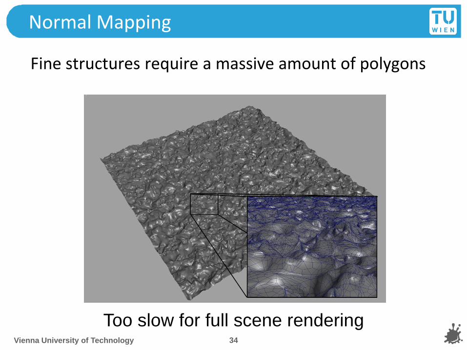
Fine structures require a massive amount of polygons
Vienna University of Technology 34
Too slow for full scene rendering
Normal Mapping
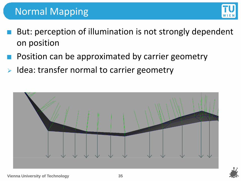
But: perception of illumination is not strongly dependent on position
Position can be approximated by carrier geometry
Idea: transfer normal to carrier geometry
Vienna University of Technology 35
Normal Mapping
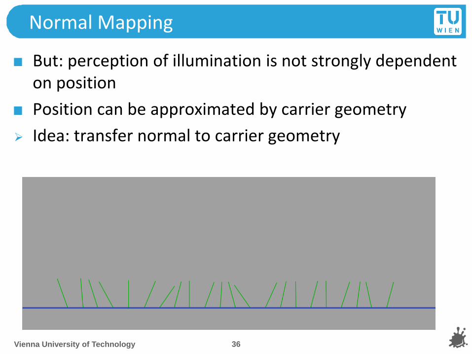
But: perception of illumination is not strongly dependent on position
Position can be approximated by carrier geometry
Idea: transfer normal to carrier geometry
Vienna University of Technology 36

Normal Mapping
Result: Texture that contains the normals as vectors
Red X
Green Y
Blue Z
Saved as range compressed bitmap ([-1..1] mapped to [0..1])
Directions instead of polygons!
Shading evaluations executed with lookup normals instead of interpolated normal
Vienna University of Technology 37

Normal Mapping
Additional result is heightfield texture
Encodes the distance of original geometry to the carrier geometry
Ralf Habel 38

Parallax normal mapping
Normal mapping does not use the heightfield
No parallax effect, surface is still flattened
Idea: Distort texture lookup according to view vector and heightfield
Good approximation of original geometry
Vienna University of Technology 39
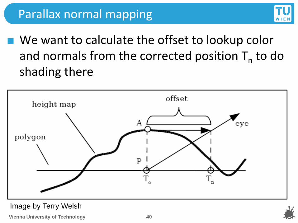
Parallax normal mapping
We want to calculate the offset to lookup color and normals from the corrected position Tn to do shading there
Vienna University of Technology 40
Image by Terry Welsh

Parallax normal mapping
Rescale heightmap h to appropriate values: hn = h*s -0.5s (s = scale = 0.01)
Assume heightfield is locally constant
Lookup heightfield at T0
Trace ray from T0 to eye with eye vector V to height and add offset:
Tn = T0 + (hn * Vx,y/Vz)
<insert your name here> 41

Offset limited Parallax normal mapping
Problem: At steep viewing angles, Vz goes to zero
Offset values approach infinity
Solution: we leave out Vz division:
Tn = T0 + (hn * Vx,y)
Effect: offset is limited
Vienna University of Technology 42
Image by Terry Welsh

Vienna University of Technology 43
Normalmap
Parallax-normalmap
Demo
Author:Terry Welsh

Bump Map
Original Bump Mapping idea has theory that is a little more involved!
Assume a (u, v)-parameterization
I.e., points on the surface P = P(u,v)
Surface P is modified by 2D height field h
Vienna University of Technology 44
surface P height field h offset surface P’
with perturbed normals N’
+ =

Mathematics
Pu, Pv : Partial derivatives:
Easy: differentiate, treat other vars as constant! (or see tangent space)
Both derivatives are in tangent plane
Careful: normal normalization…
N(u,v) = Pu x Pv
Nn = N / |N|
Displaced surface:
P’(u,v) = P(u,v) + h(u,v) Nn(u,v) Vienna University of Technology 45
),(),( vuu
PvuPu

Mathematics
Perturbed normal: N’(u,v) = P’u x P’v
P’u = Pu + hu Nn + h Nnu ~ Pu + hu Nn (h small)
P’v = Pv + hv Nn + h Nnv ~ Pv + hv Nn
N’ = N + hu (Nn x Pv) + hv (Pu x Nn)
= N + D “offset vector”
(D is in tangent plane)
Vienna University of Technology 46
P’ = P + h Nn

Cylinder Example
Goal: N’ = N + hu (Nn x Pv) + hv (Pu x Nn)
P(u,v) = (r cos u, r sin u, l v), u = 0.. 2 Pi, v = 0..1
Pu = (- r sin u, r cos u, 0), |Pu| = r
Pv = (0, 0, l), |Pv| = l
N = (r l cos u, r l sin u, 0), |N| = r l
Nn = (cos u, sin u, 0)
Nn x Pv = l (sin u, -cos u, 0)
Pu x Nn = (0, 0, -r)
Vienna University of Technology 47
r
l
Pu
Pv
N Nn x Pv Pu x Nn

Bump Mapping Issues
Dependence on surface parameterization
D = f(Pu, Pv)
Map tied to this surface don’t want this!
What to calculate where?
Preproces, per object, per vertex, per fragment
Which coordinate system to choose?
Vienna University of Technology 48

Coordinate Systems
Problem: where to calculate lighting?
Object coordinates
Native space for normals (N)
World coordinates
Native space for light vector (L), env-maps
Not explicit in OpenGL!
Eye Coordinates
Native space for view vector (V)
Tangent Space
Native space for normal maps Vienna University of Technology 49
Proj Matrix
TBN Matrix
Tangent Space
Object Space
World Space
Eye Space
Clip Space
Model Matrix
View Matrix

Basic Algorithm (Eye Space)
For scene (assume infinite L and V) Transform L and V to eye space and normalize
Compute normalized H (for specular)
For each vertex Transform Nn, Pu and Pv to eye space
Calculate B1 = Nn x Pv, B2 = Pu x Nn, N = Pu x Pv
For each fragment Interpolate B1, B2, N
Fetch (hu, hv) = texture(s, t)
Compute N’ = N + hu B1 + hv B2
Normalize N’
Using N’ in standard Phong equation
Vienna University of Technology 50

Tangent Space
Concept from differential geometry
Set of all tangents on a surface
Orthonormal coordinate system (frame) for each point on the surface:
Nn(u,v) = Pu x Pv / |Pu x Pv| T = Pu / |Pu| B = Nn x T
A natural space for normal maps
Vertex normal N = (0,0,1) in this space!
Vienna University of Technology 51
N
T
B

Parametric Example
Cylinder Tangent Space:
Nn(u,v) = Pu x Pv / |Pu x Pv| T = Pu / |Pu| B = Nn x T
Tangent space matrix: TBN column vectors
Vienna University of Technology 52
Pu
r
l
Pv
N
Nn
T
B

Fast Algorithm (Tangent Space)
“Normal Mapping”
For each vertex
Transform light direction L and eye vector V to tangent space and normalize
Compute normalized Half vector H
For each fragment
Interpolate L and H
Renormalize L and H
Fetch N’ = texture(s, t) (Normal Map)
Use N’ in shading
Vienna University of Technology 53

Square Patch Assumption
B = Pv / |Pv|
Decouples bump map from surface!
Recall formula:
Convert to tangent space:
Nn x Pv = - T |Pv|
Pu x Nn = - B |Pu|
|N| = |Pu x Pv| = |Pu| |Pv| sin α
N’ = N - hu T |Pv| - hv B |Pu| divide by |Pu| |Pv|
N’ ~ Nn sin α - hu/ |Pu| T - hv / |Pv| B Vienna University of Technology 54
N
T
B
N’ = N + hu (Nn x Pv) + hv (Pu x Nn)

Square Patch Assumption
N’ ~ Nn sin α - hu / |Pu| T - hv / |Pv| B
Square patch sin α = 1
|Pu| and |Pv| assumed constant over patch
N’ ~ Nn – (hu / k) T – (hv / k) B = Nn + D
Vienna University of Technology 55

Offset Bump Maps
N’ ~ Nn – (hu / k) T – (hv / k) B = Nn + D
In tangent space (TBN):
Nn = (0, 0, 1), D = (- hu / k, - hv / k, 0)
“Scale” of bumps: k
Apply map to any surface with same scale
Alternative: D = (- hu, - hv, 0)
Apply k at runtime
hu, hv : calculated by finite differencing from height map
Vienna University of Technology 56

Normal Maps
Also: normal perturbation maps
N’ ~ Nn – (hu / k) T – (hv / k) B = R Nn
R: rotation matrix
In tangent space (TBN):
Nn = (0, 0, 1) N’ third row of R
N’ = Normalize(- hu / k, - hv / k, 1)
“Scale” of bumps: k
Comparison to offset maps:
Need 3 components
Better use of precision (normalized vector) Vienna University of Technology 57

Creating Tangent Space
Trivial for analytically defined surfaces
Calculate Pu, Pv at vertices
Use texture space for polygonal meshes
Induce from given texture coordinates per triangle
P(u, v) = a u + b v + c = Pu u + Pv v + c !
9 unknowns, 9 equations (x,y,z for each vertex)!
Transformation from object space to tangent space
Vienna University of Technology 58
Tx
Ty
Tz
Bx
By
Bz
Nx
Ny
Nz
Lox Loy Loz Ltx Lty Ltz =

Creating Tangent Space - Math
P(s, t) = a s + b t + c, linear transform!
Pu(s,t) = a, Pv(s,t) = b
Texture space:
u 1 = (s1,t 1)-(s 0,t 0), u 2 = (s2,t 2)-(s 0,t 0)
Local space:
v 1 = P1-P 0, v 2 = P2-P 0
[Pu Pv] u 1 = v 1, [Pu Pv] u 2 = v 2
Matrix notation:
[Pu Pv] [u 1 u 2] = [v 1 v 2]
Vienna University of Technology 59

Creating Tangent Space - Math
[Pu Pv] [u 1 u 2] = [v 1 v 2]
[Pu Pv] = [v 1 v 2] [u 1 u 2]-1
[u 1 u 2]-1 = 1/| u 1 u 2 | [u 2y -u 2x ]
[-u 1y u 1x]
Result: very simple formula!
Finally: calculate tangent frame (for triangle):
T = Pu / |Pu| B = Nn x T
Vienna University of Technology 60

Creating Tangent Space
Example for key-framed skinned model
Note: average tangent space between adjacent triangles (like normal calculation)
bump-skin height field decal skin (unlit!) Vienna University of Technology 61

Quake 2 Example
Vienna University of Technology 62
) + ( ( ) =
Diffuse Gloss Specular Decal
Final
result!
Note: Gloss map
defines where to
apply specular

Normal map Example
Vienna University of Technology 63
+
Model by Piotr Slomowicz

Normal map Example
Vienna University of Technology 64

Normal map Example
Vienna University of Technology 65
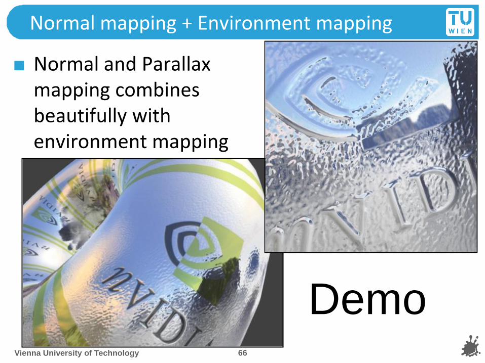
Normal mapping + Environment mapping
Normal and Parallax mapping combines beautifully with environment mapping
Vienna University of Technology 66
Demo

EMNM (World Space)
For each vertex Transform V to world space Compute tangent space to world space transform (T, B, N)
For each fragment Interpolate and renormalize V Interpolate frame (T, B, N) Lookup N’ = texture(s, t) Transform N’ from tangent space to world space Compute reflection vector R (in world space) using N’ Lookup C = cubemap(R)
Vienna University of Technology 67

Normal and Parallax Normal Map Issues
Artifacts
No shadowing
Silhouettes still edgy
No parallax for Normal mapping
Parallax Normal Mapping
No occlusion, just distortion
Not accurate for high frequency height-fields (local constant heightfield assumption does not work)
No silhouettes
Vienna University of Technology 68

Normal Mapping Issues
Normal Mapping Effectiveness
No effect if neither light nor object moves!
In this case, use light maps
Exception: specular highlights
Vienna University of Technology 69

Horizon Mapping
Improve normal mapping with (local) shadows
Preprocess: compute n horizon values per texel
Runtime:
Interpolate horizon values
Shadow accordingly
Eduard Gröller, Stefan Jeschke 70
u
v
8 horizon values

Horizon Mapping Examples
Eduard Gröller, Stefan Jeschke 71

Relief Mapping
At runtime: perform ray casting in the pixel shader
Calculate entry (A) and exit point (B)
March along ray until intersection with height field is found
Binary search to refine the intersection position
Vienna University of Technology 72

Relief Mapping Examples
Eduard Gröller, Stefan Jeschke 73
Texture mapping
Relief mapping
Parallax mapping

Speed considerations
Parallax-normalmapping
~ 20 ALU instructions
Relief-mapping
Marching and binary search:
~300 ALU instructions
+ lots of texture lookups
Vienna University of Technology 74

Advanced Methods
Higher-Order surface approximation relief mapping
Surface approximated with polynomes
Produces silhouettes
Prism tracing
Produces near-correct silhouette
Many variations to accelerate tracing
Cut down tracing cost
Shadows in relief
Vienna University of Technology 75

Normal and Parallax normal map Toolset
DCC Packages (Blender, Maya, 3DSMax)
Nvidia Normalmap Filter for Photoshop or Gimp Normalmap filter
Create Normalmaps directly from Pictures
Not accurate!, but sometimes sufficient
NVIDIA Melody
xNormal (free)
Crazybump (free beta)
Much better than PS/Gimp Filters!
Tangent space can be often created using graphics/game engine
Vienna University of Technology 76

Tipps
Download FXComposer and Rendermonkey
Tons of shader examples
Optimized code
Good IDE to play around
Books:
GPU Gems Series
ShaderX Series
Both include sample code!
Vienna University of Technology 77