Real-time observation of transient electron density in ...
17
Real-time observation of transient electron density in water irradiated with tailored femtosecond laser pulses This article has been downloaded from IOPscience. Please scroll down to see the full text article. 2012 New J. Phys. 14 075021 (http://iopscience.iop.org/1367-2630/14/7/075021) Download details: IP Address: 141.51.197.191 The article was downloaded on 31/08/2012 at 12:06 Please note that terms and conditions apply. View the table of contents for this issue, or go to the journal homepage for more Home Search Collections Journals About Contact us My IOPscience
Transcript of Real-time observation of transient electron density in ...

Real-time observation of transient electron density in water irradiated with tailored
femtosecond laser pulses
This article has been downloaded from IOPscience. Please scroll down to see the full text article.
2012 New J. Phys. 14 075021
(http://iopscience.iop.org/1367-2630/14/7/075021)
Download details:
IP Address: 141.51.197.191
The article was downloaded on 31/08/2012 at 12:06
Please note that terms and conditions apply.
View the table of contents for this issue, or go to the journal homepage for more
Home Search Collections Journals About Contact us My IOPscience

T h e o p e n – a c c e s s j o u r n a l f o r p h y s i c s
New Journal of Physics
Real-time observation of transient electron densityin water irradiated with tailored femtosecondlaser pulses
C Sarpe, J Kohler, T Winkler, M Wollenhaupt and T Baumert1
Universitat Kassel, Institut fur Physik und CINSaT, Heinrich-Plett-Strasse 40,D-34132 Kassel, GermanyE-mail: [email protected]
New Journal of Physics 14 (2012) 075021 (16pp)Received 6 March 2012Published 24 July 2012Online at http://www.njp.org/doi:10.1088/1367-2630/14/7/075021
Abstract. Ionization mechanisms in water irradiated with bandwidth-limitedand temporally asymmetric femtosecond laser pulses are investigated viaultrafast spectral interferometry. By using a novel common-path interferometerwith an enlarged temporal measurement window, we directly observe thedynamics of free-electron plasma generated by shaped pulses. We foundthat a temporally asymmetric pulse and its time-reversed counterpart addressmultiphoton and avalanche ionization mechanisms in a different fashion. Positivethird-order dispersion shaped pulses produce a much higher free-electrondensity than negative ones at the same fluence, instantaneous frequency andfocusing conditions. From the experimental data obtained after irradiation withbandwidth-limited and shaped pulses the multiphoton and avalanche coefficientswere determined using a generic rate equation. We conclude that temporaltailored femtosecond pulses are suitable for manipulation of the initial steps inlaser processing of high band gap materials.
1 Author to whom any correspondence should be addressed.
New Journal of Physics 14 (2012) 0750211367-2630/12/075021+16$33.00 © IOP Publishing Ltd and Deutsche Physikalische Gesellschaft

2
Contents
1. Introduction 22. Experimental details 43. Optical properties of a Drude plasma relevant to data evaluation 74. Experimental results and discussion 8
4.1. Bandwidth-limited femtosecond pulses . . . . . . . . . . . . . . . . . . . . . . 84.2. Third-order dispersion shaped pulses . . . . . . . . . . . . . . . . . . . . . . . 11
5. Numerical simulations 136. Summary and conclusion 15Acknowledgment 15References 15
1. Introduction
The interaction of intense ultrashort laser pulses with transparent dielectrics has attracted muchattention in the last decade due to its applications in precise micro- and nano-processing (see,for example, [1, 2] and references therein) or medical surgery [3, 4]. These materials aretransparent for light in the visible and near infrared spectral region but they become highlyabsorptive if laser pulses of sufficient intensity are used. On this basis, high-intensity ultrashortlaser pulses are a unique tool in processing and structuring transparent dielectrics. For thesematerials the first step in the ablation process is optical breakdown in which a high density offree electrons is generated through nonlinear ionization processes. The free electrons absorbenergy from the laser pulse, transfer it to the ions, atoms and molecules, and on a longertimescale ablation takes place. The quality of the ablation process is strongly dependent on theprimary processes involved in the laser–matter interaction. Even if it is well known that the freeelectrons are generated through multiphoton, avalanche or tunneling ionization [5–8], thecontribution of each ionization mechanism for different materials and laser pulse parametersis not completely understood. Englert et al [9] showed that by using temporally asymmetricshaped femtosecond laser pulses created via applying third-order dispersion (TOD) in a Fouriertransform pulseshaper the basic ionization mechanisms can be controlled in the case of solidtransparent dielectrics. In that case, TOD-tailored laser pulses showed different thresholds forablation for a temporal asymmetric pulse and its time-reversed counterpart. In addition, holeswith a diameter one order of magnitude below the optical diffraction limit were produced.Even if the transient electron density generated by shaped pulses was not measured in theabove mentioned experiments, a theoretical model based on the interplay of multiphoton andavalanche ionization suggested that the positive TOD pulses, starting with a high intensity sub-pulse followed by a sequence of low intensity sub-pulses create higher free-electron density incomparison to their time-reversed counterpart. The results obtained by numerically solving themultiple rate equations [7] were in qualitatively good agreement with the post mortem ablationanalysis for the thresholds of material processing.
In this contribution, we present our studies to investigate in real-time the free-electrondensity of transient plasma produced by shaped temporally asymmetric ultrashort laser pulses ina thin water jet. Water is an amorphous semiconductor with an energy band gap of 6.5 eV [10].
New Journal of Physics 14 (2012) 075021 (http://www.njp.org/)

3
The study of breakdown dynamics in water is important first of all for micro-processing ofbiological samples and micro-analytics [4, 11]. In addition, due to the fact that the opticalbreakdown primary processes are general ones [8], useful information on the behavior ofsolid dielectrics can also be obtained. Because the laser-induced phenomena are extremelyfast, only optical methods can be used to study the dynamics of the free-carriers by probingchanges in the optical properties of the laser-excited region. It is generally assumed that materialablation occurs when the concentration of free carriers is on the order of Ne ∼ 1021 cm−3,whereas the real-time experimental measurement of density is still a challenging task. Ultrafastimaging [12–15] and time-resolved reflection microscopy [16] can provide useful informationabout free-carrier dynamics by measuring the transmission or the reflection coefficient of theelectron–hole plasma but these techniques are either not accurate enough or can be used onlyfor laser intensities close to the breakdown threshold. Interferometric techniques can accessboth the real and imaginary parts of the complex dielectric function and very small changesin the optical properties of free-electron plasma can be detected. Spatial [17, 18] and spectralinterferometry [19–22] were successfully used to measure the dynamics of free-electron plasmaafter irradiation with intense ultrashort laser pulses. In spatial interferometry, thin transparentsamples are placed in one arm of a Mach–Zehnder interferometer and are excited by a strongfemtosecond pulse. The image is produced by the interfering probe pulse passing through thedielectric sample and the reference one propagating in the other arm of the interferometer. Thephase and amplitude obtained by Fourier analysis of the interference picture provide informationabout the complex dielectric index of the plasma. By changing the time delay between the pumpand the pair of reference and probe pulses, complete dynamics can be recorded. In spectralinterferometry both the pump and reference pulses, separated by a fixed time delay, propagatethrough the sample to monitor the changes of the refractive index produced by the pumppulse. The probe and reference pulses (created in a Michelson-type interferometer) are sentto an imaging spectrometer and a frequency–domain interference is produced. If the time delaybetween the pump and the pair reference–probe pulses (generally the second harmonic of thepump) is adjusted in such a way that the reference pulse propagates through the interaction areabefore the pump creates the free carriers and the probe after their creation, the phase differenceand the contrast of the interference fringes gives direct information about the optical propertiesof plasma. The advantage of spatial interferometry is its ability to directly monitor the dynamicson a longer timescale but the experimental set-up is more complicated. Spectral interferometryis a simpler and more robust technique, but the time delay between the reference and the probeis generally limited to a few ps even if a high-resolution spectrometer is used to resolve theinterference fringes. In order to monitor the dynamics of the free-carrier plasma producedby temporally shaped pulses spread out in time one needs a temporal measurement windowbroader than the duration of the temporally tailored pulses. In our study, we used an improvedspectral interferometer in order to circumvent the above-mentioned disadvantage of thetechnique.
We make use of a common-path interferometer in which the reference and probepulses are generated as ordinary and extraordinary beams when the light propagatesthrough birefringent crystals. Our approach was stimulated by van Dijk et al [23] wherea set-up for single nanoparticles detection is described. The common-path approach leads to astability much higher than in conventional interferometers. To overcome the problem that alarge measurement window would require a high-resolution spectrometer we decreased thedelay between interfering pulses again with the help of another birefringent crystal before
New Journal of Physics 14 (2012) 075021 (http://www.njp.org/)

4
analysis. This technique including an enlarged measurement window was hitherto not used incombination with spectral interference. We demonstrate that it is a powerful tool to investigatethe dynamics of ultrafast processes on a longer timescale.
The paper is organized as follows. We describe in section 2 the experimental set-upand the principle of spectral interferometry. In section 3, we discuss the optical properties offree-electron plasma relevant to our data evaluation. The experimental results for irradiationwith both bandwidth-limited and temporal asymmetrical shaped femtosecond laser pulses arepresented in section 4. In section 5, a simple model based on a generic rate equation is usedto obtain the multiphoton and avalanche coefficients and to simulate the transient free-electrondensity for shaped pulses. We conclude the paper with a brief summary.
2. Experimental details
The femtosecond pulses used in this experiment are generated by a Femtolasers FemtopowerPro Ti:sapphire multipass amplifier operating at a central wavelength of 785 nm. At the outputof the amplifier the temporal duration of the pulses is 30 fs, the repetition rate is 1 kHz and themaximum energy is 800 µJ per pulse. A schematic representation of the experimental set-up isdrawn in figure 1. The beam splitter BS reflects 50% of the incoming laser beam and sends itto a liquid crystal modulator-based pulse shaper (Jenoptik SLM-S640d). The description of thedevice can be found in [24, 25]. In order to tune the intensity of the pump pulses a steppermotor-controlled achromatic half-wave plate (Bernhard Halle) and a high-contrast polarizer(Codixx colorPol VISIR CW 02) are used. After passing through a dielectric recombinationmirror the pump beam is focused onto the surface of the free flowing laminar water jet usinga 50 mm focal length lens. The beam transmitted through the beam splitter is first directed toan optical delay line driven by a computer-controlled stepper motor in order to control thetime delay between the pulses. Then, the second harmonic is generated in a 200 µm thickβ-BBO nonlinear optical crystal. Before passing through the crystal, the polarization directionis rotated by 90◦ with the help of a λ/2-wave plate in order to ensure horizontal polarization forthe second harmonic pulses before they enter the prism compressor used to pre-compensate thestrong positive group delay dispersion of the following optical elements. At the same time, byusing the prism compressor, the residual fundamental is completely blocked.
In order to create the reference and probe pulses, a common-path interferometer wasdesigned for this experiment. The 400 nm pulse is impinging at normal incidence on thesurface of an α-BBO birefringent crystal. This crystal is oriented in such a way that a lightpulse propagating through it is split into an ordinary and an extraordinary pulse with equalintensities, orthogonally polarized at ±45◦ relative to the horizontal. The α-BBO crystalis a negative uniaxial medium. Its two refractive indices at 400 nm are no = 1.6963 andne = 1.5493 respectively. The extraordinary pulse precedes the ordinary one by a time delaydirectly dependent on the crystal length. In comparison to Michelson or Mach–Zehnderinterferometers, the common-path interferometer based on birefringent crystals delivers thefollowing advantages: first of all, the probe and reference beams have an inherent spatialoverlap and the beam profiles are identical. In addition, the stability of the set-up is dramaticallyincreased as environmental perturbations such as temperature and air pressure fluctuations inthe laboratory induce a time drift in the two arms of beam splitter-based interferometers.
The blue pulses are spatially overlapped with the pump beam and propagate in the sameway through the sample. The dielectric medium used in this experiment is a thin planar distilled
New Journal of Physics 14 (2012) 075021 (http://www.njp.org/)

5
Figure 1. (a) Experimental set-up. Bandwidth-limited or shaped femtosecondlaser pulses are focused on the surface of a free flowing planar water jet togenerate high-density free-electron plasma. The time sequence and relativepolarization for the spectral interference measurements is detailed in (b). A time-delayed pulse is frequency-doubled to 400 nm and passes through a birefringentcrystal α-BBO 1. This one creates a pair of orthogonally polarized pulses witha separation of 6.5 ps. The reference and probe pulses propagate through theinteraction area together with the pump and probe the changes in the opticalproperties. A second birefringent crystal α-BBO 2 decreases the temporalseparation between the blue pulses to 0.2 ps. After passing through a polarizerthe frequency–domain interference pattern is recorded. BS: beam splitter; HW:half-wave plate; P: polarizers; LCM: liquid crystal modulator; DM: dielectricmirror; FL: focusing lens; WJ: free flowing planar water jet; SP: short-pass colorfilter; MO: microscope objective; TL: tube lens.
water jet produced by a stainless steel nozzle. The thickness of the water jet was measured byspectral interferometry, analyzing the interference fringes of the spectrally broad fundamentalbeam reflected on the front and respectively the rear water–air interface (set-up not shown in
New Journal of Physics 14 (2012) 075021 (http://www.njp.org/)
6
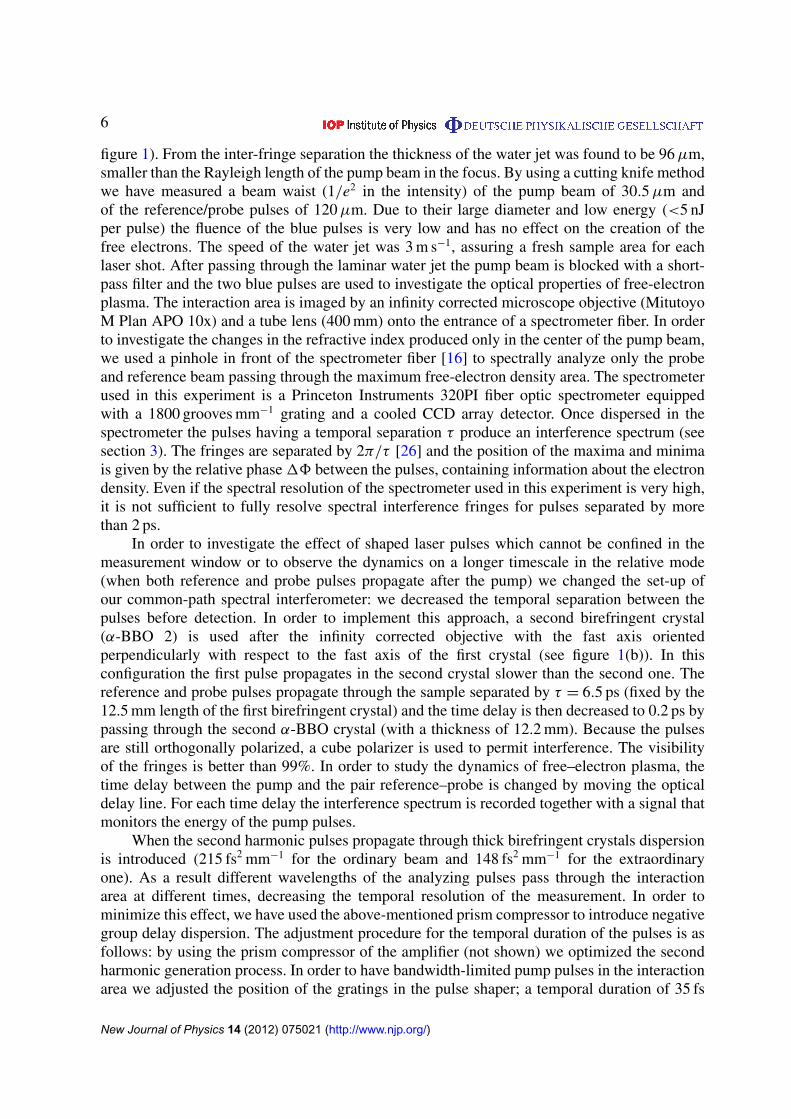
figure 1). From the inter-fringe separation the thickness of the water jet was found to be 96 µm,smaller than the Rayleigh length of the pump beam in the focus. By using a cutting knife methodwe have measured a beam waist (1/e2 in the intensity) of the pump beam of 30.5 µm andof the reference/probe pulses of 120 µm. Due to their large diameter and low energy (<5 nJper pulse) the fluence of the blue pulses is very low and has no effect on the creation of thefree electrons. The speed of the water jet was 3 m s−1, assuring a fresh sample area for eachlaser shot. After passing through the laminar water jet the pump beam is blocked with a short-pass filter and the two blue pulses are used to investigate the optical properties of free-electronplasma. The interaction area is imaged by an infinity corrected microscope objective (MitutoyoM Plan APO 10x) and a tube lens (400 mm) onto the entrance of a spectrometer fiber. In orderto investigate the changes in the refractive index produced only in the center of the pump beam,we used a pinhole in front of the spectrometer fiber [16] to spectrally analyze only the probeand reference beam passing through the maximum free-electron density area. The spectrometerused in this experiment is a Princeton Instruments 320PI fiber optic spectrometer equippedwith a 1800 grooves mm−1 grating and a cooled CCD array detector. Once dispersed in thespectrometer the pulses having a temporal separation τ produce an interference spectrum (seesection 3). The fringes are separated by 2π/τ [26] and the position of the maxima and minimais given by the relative phase 18 between the pulses, containing information about the electrondensity. Even if the spectral resolution of the spectrometer used in this experiment is very high,it is not sufficient to fully resolve spectral interference fringes for pulses separated by morethan 2 ps.
In order to investigate the effect of shaped laser pulses which cannot be confined in themeasurement window or to observe the dynamics on a longer timescale in the relative mode(when both reference and probe pulses propagate after the pump) we changed the set-up ofour common-path spectral interferometer: we decreased the temporal separation between thepulses before detection. In order to implement this approach, a second birefringent crystal(α-BBO 2) is used after the infinity corrected objective with the fast axis orientedperpendicularly with respect to the fast axis of the first crystal (see figure 1(b)). In thisconfiguration the first pulse propagates in the second crystal slower than the second one. Thereference and probe pulses propagate through the sample separated by τ = 6.5 ps (fixed by the12.5 mm length of the first birefringent crystal) and the time delay is then decreased to 0.2 ps bypassing through the second α-BBO crystal (with a thickness of 12.2 mm). Because the pulsesare still orthogonally polarized, a cube polarizer is used to permit interference. The visibilityof the fringes is better than 99%. In order to study the dynamics of free–electron plasma, thetime delay between the pump and the pair reference–probe is changed by moving the opticaldelay line. For each time delay the interference spectrum is recorded together with a signal thatmonitors the energy of the pump pulses.
When the second harmonic pulses propagate through thick birefringent crystals dispersionis introduced (215 fs2 mm−1 for the ordinary beam and 148 fs2 mm−1 for the extraordinaryone). As a result different wavelengths of the analyzing pulses pass through the interactionarea at different times, decreasing the temporal resolution of the measurement. In order tominimize this effect, we have used the above-mentioned prism compressor to introduce negativegroup delay dispersion. The adjustment procedure for the temporal duration of the pulses is asfollows: by using the prism compressor of the amplifier (not shown) we optimized the secondharmonic generation process. In order to have bandwidth-limited pump pulses in the interactionarea we adjusted the position of the gratings in the pulse shaper; a temporal duration of 35 fs
New Journal of Physics 14 (2012) 075021 (http://www.njp.org/)

7
was measured with a spectrogram-based method. The prism compressor used for the secondharmonic was iteratively adjusted in order to remove the chirp in the probe beam, when all thewavelengths contained in the probe pulse arrive in the interaction area simultaneously with thepump. By optical Kerr effect (OKE) cross-correlation we measured a probe pulse duration of55 fs.
3. Optical properties of a Drude plasma relevant to data evaluation
The electron densities after laser irradiation are derived from the data assuming homogeneousexcitation across the interaction and using the Drude formalism. We measure a phase shift and achange in transmission. Here, we summarize how these quantities can be used to derive electrondensity for later reference. The optical properties of laser-induced plasma can be described usinga generalization of the Lorentz–Drude dielectric function [27]:
ε (ω) = ε10−ω2
pl
ω2 + i ω
τc
, (1)
where ε10 describes the contribution of bound electrons, ωpl = e ·
√Ne
ε0meis the plasma frequency,
τc is the collision time, ε0 denotes the vacuum permittivity, me is the electron mass and e itselectric charge. In our experiment, we investigate the dielectric function ε(ω) with an ultrashortprobe laser pulse around its central frequency ω0 corresponding to a wavelength of 400 nm.Assuming that the medium is a dielectric one (magnetic permeability µ = 1), the complexrefractive index of the Drude plasma is the square root of the dielectric function:
nDrude =
√ε(ω)µ ≈
√ε(ω). (2)
The time-dependent free-electron density Ne(t)—on which the plasma frequency isdependent—produces changes in the complex refraction index:
1nDrude(t) = nDrude(Ne)−nDrude(Ne = 0) = −1
2n0
(ωpl
ω
)2 1
1−1/iωτc, (3)
with n0 =√
ε10 being the linear refractive index of the unperturbed dielectric medium. Inaddition to the changes produced in the refractive index by the free electrons, in spectralinterference methods the contribution of the transient OKE to the refractive index has also to betaken into account:
n(t) = n0 + 1nKerr(t) + 1nDrude(t). (4)
The Kerr effect induces a transient positive contribution to the refractive index, proportionalto the pump laser intensity:
1nKerr(t) = n2 I (t), (5)
where n2 is the nonlinear refractive index.In the absolute mode of spectral interferometry (when the reference pulse propagates before
the pump and the probe after), the probe pulse only monitors the changes produced by thefree carriers: a phase shift due to the changes in the real refractive index and an attenuationproduced by plasma absorption. If the electric fields of the reference and probe pulses are:Eref(t) = E0(t)eiω0t and Eprobe(t) =
√T E0(t−τ)ei[ω0(t−τ)+18] (where E0(t) is the envelope,
New Journal of Physics 14 (2012) 075021 (http://www.njp.org/)

8
T is the intensity transmission coefficient and τ the time delay between the blue pulses), thepower spectrum is
S(ω) = S0(ω)[1 + T + 2√
T cos(ωτ−18)]. (6)
The phase shift 18 contains information about the real part of the refractive index and thetransmission coefficient T about the free-electron plasma absorption. Assuming homogeneousdistribution of free-electron density along the sample [18] the phase shift 18 and the opticaldensity OD are obtained by taking the real and the imaginary parts of 1nDrude(t):
18 =2π
λL Re(1nDrude) = −
π L · ω2pl
λn0
(ω2 + 1
τ 2c
) , (7)
OD = −4π
λL · Im(1nDrude) =
2π L · ω2pl
λn0ωτc
(ω2 + 1
τ 2c
) . (8)
Accordingly, the intensity transmission coefficient T takes the following form:
T = exp(−OD) = exp
−2π L · ω2
pl
λn0ωτc
(ω2 + 1
τ 2c
) , (9)
where L is the sample thickness and λ is the probe wavelength.Taking (7), (8) and (1) and assuming a homogeneous electron density across the sample,
the free-electron density is directly proportional to the phase shift and the optical density:
Ne =meε0
πe2·
n0λ
L·
(ω2 +
1
τ 2c
)· |18| =
meε0
2πe2·
n0λ
L· τcω ·
(ω2 +
1
τ 2c
)· OD. (10)
Equations (7) and (8) contain the collision time τc, which can be experimentally derivedfrom the phase shift and transmission measurements according to
τc =2 |18|
ωOD. (11)
4. Experimental results and discussion
4.1. Bandwidth-limited femtosecond pulses
In figure 2(a), we display the frequency–domain interference spectra for three values of thepump–probe time delay. For negative times both reference and probe pulses pass through thesample before the pump creates free electrons and the spectrum shows the spectral interferenceof two identical pulses. At 2 ps the pump pulse is confined in the measurement window andthe probe pulse monitors the optical properties of free-electron plasma. The free electronsshow a metal-like behavior within the irradiated volume resulting in a decrease of the realpart of the refractive index thus producing a negative phase shift. For pump–probe delayslonger than the measurement window both reference and probe interrogate the sample afterpump interaction. This is the relative mode in spectral interference measurements and can beused to observe the dynamics on timescales longer than the measurement window defined bythe delay between reference and probe. In this paper, we will concentrate only on the early
New Journal of Physics 14 (2012) 075021 (http://www.njp.org/)

9
Figure 2. Frequency–domain interference spectra obtained for pump pulseenergy of 3.2 µJ. (a) Pseudo-color representation of the spectral interference asa function of the pump–probe time delay. For negative times the pump pulsepasses through the sample temporally after the reference and probe. In themeasurement window the pump is confined between the two and in the relativemode (after 6.5 ps) the pump propagates before the two blue pulses. (b) Spectrafor different time delays. Note the phase shift and the decrease of the fringevisibility introduced by the free-electron plasma.
time dynamics obtained in the absolute mode of spectral interferometry. From the spectralinterference data the phase and the transmission coefficient of the probe pulse are calculatedby inverse Fourier transformation. The values of the obtained phase shift and transmissioncoefficient were cross-checked with the values obtained from the shifts of the maxima andminima of the interference fringes. By changing the pump–probe delay the dynamics of theplasma can be constructed. Figure 3 shows the temporal evolution of the phase shift and of thetransmission coefficient for a 35 fs bandwidth-limited pulse with respect to different pump pulseenergies.
The OKE contribution is proportional to the pump laser intensity (see equation (5)) andit appears only during the pump pulse duration. When the pump and probe pulses overlap(time zero in the figure) there is an increase of the refractive index influencing only theprobe pulse and not the reference pulse; this results in an increased optical path between thereference and the probe pulse and a positive shift of the interference fringes is observed. Whenthe pump propagates through the sample simultaneously with the reference pulse, only thelatter experiences an increase in the refractive index. However, the optical path between thereference and the probe decreases in this case and an additional negative phase shift (at 6.5 ps infigure 3(a)) appears. When both—Drude and Kerr—contributions are present the interpretationof the measured phase shift and transmission coefficient is ambiguous. In the measurementwindow there is only a negative phase shift produced by free electrons (equation 7). Allour analysis is therefore performed well within the measurement window. For high energiesthe absolute value of the phase shift decreases in the measurement window and has a smallpositive value after 6.5 ps (relative mode of spectral interferometry). This is an indication ofrecombination and further work will be devoted to investigate this effect. For low energiesthe assumption of homogeneous excitation inside the sample along the propagation directionholds [18, 22] and the phase shift in this case is directly proportional to the electron density.This is the region where we will concentrate our data evaluation and discussion.
New Journal of Physics 14 (2012) 075021 (http://www.njp.org/)

10
Figure 3. Evolution of phase shift (a) and of probe transmission coefficient T (b)as function of time, after excitation with bandwidth-limited pump pulses (35 fs)for different pump energies. At time zero and at 6.5 ps the pump pulse overlapswith the probe and reference pulses respectively and the phase shift induced bythe transient OKE is observed. In the measurement window the negative phaseshift and the decrease of the transmission coefficient are due to the generation offree electrons by the pump pulse.
Figure 4. Absolute phase shift 18 and optical density OD as a functionof the peak pump laser intensity for 35 fs bandwidth-limited pulses togetherwith a fit taking a five-photon ionization process into account (black solidlines). On the right scale the calculated free-electron density assuming ahomogeneous distribution (realistic for low laser intensities) is also shown. Thelight gray window represents the intensity in which an electron collision time of1.6 ± 0.3 fs was determined.
Figure 4 presents the dependence of the absolute phase shift and of the optical density onthe peak pump laser intensity (which is two times higher than the 1/e2 averaged intensity)at a time delay of 1.5 ps after the creation of the free electrons. For low intensities thedependence follows a power law indicated by the black lines in figure 4, with an exponentof 5.1 ± 0.2 for the phase shift and 5.2 ± 0.2 for the optical density. This hints at a five-photon
New Journal of Physics 14 (2012) 075021 (http://www.njp.org/)

11
ionization process in the range of 0.1–0.8 rad as also expected from the band gap of 6.5 eVmentioned in the introduction section. By increasing the pump intensity further, the absolutephase shift also increases, but the assumption of a longitudinal homogeneous distribution isnot valid anymore and the deviation from the line which indicates the multiphoton process isevident. In this intensity regime a model describing the propagation of light into the dielectricmedium [28] will be considered in future investigations. The phase shift reaches a maximumat 4.8 × 10¹² W cm−2, for higher intensities it starts to decrease. This behavior was alsoobserved for solid dielectrics [18] and it was attributed to a strong inhomogeneous distributionof free-electron density in longitudinal direction. The visible plasma spark was observed at9.6 × 1012 W cm−2 peak intensity. Previous studies reported an averaged threshold intensityof 6.6 × 10¹² W cm−2 for which the longitudinal distribution of free-electron plasma is on theorder of 1 µm [16]. For these values axial distribution acts as a limiting factor in the observedphase shift even if free-electron density is high. A thinner sample provides higher accuracy inthe high-intensity excitation regime, whereas a thicker one provides higher resolution for thelow-intensity regime. We consider a 100 µm thick sample as a good compromise to study therole of different ionization mechanisms. The optical density is situated below the phase shiftbut roughly follows the same dependence on pump laser intensity. From the two curves theDrude collision time can be obtained by using equation (11); the value of the collision timewas measured to be τc = 1.6 ± 0.3 fs in the intensity range indicated in the figure, where theassumption of a homogeneous distribution is realistic. This value is in good agreement withvalues presented in the literature from 1.2 fs [16] to 1.7 fs [4].
4.2. Third-order dispersion shaped pulses
We now turn to the topic of control, i.e. how temporally asymmetric laser pulses and theirtemporal inverted counterparts affect the electron densities when the same fluence is applied.Temporal asymmetric laser pulses were created via Fourier transform pulse shaping applyinga third-order spectral phase function (TOD) [29]: φ(ω) =
φ3
3! (ω−ω0)3. The dynamics of the
phase shift in the case of TOD-tailored pulses is more complicated when compared to the caseof bandwidth-limited ones due to the interplay of transient OKE and the contribution of freeelectrons. TOD phase shaped pulses consist of trains of pulses (see insets to figure 5 and alsofigure 7) [30]. In the case of positive TOD the first pulse is the strongest one, followed by weakerpulses whereas in the case of negative TOD the intensity of the sub-pulses in the train increasesin time. In figure 5(a), the transient phase shift produced by +600 000 fs3 TOD shaped pulsesis presented. By changing the time delay between the pump and the probe pulses, at time zerothe first most intense sub-pulse of the train will produce a positive phase shift and eventuallyfree-electron plasma sufficiently dense to be detected.
The absolute value of the negative phase shift produced by the Drude electrons decreasesdue to the transient OKE produced by the components of the stretched pulse overlapping in timewith the probe. The electron density created by such a pulse was analyzed from the transientphase shift at a time delay longer than the temporal distribution of the shaped pulse. In the caseof negative TOD shaped pulses, by changing the time delay, the probe will first overlap with thelow intensity pulses of the pump, which will generate a positive phase shift in the interferencepicture. If the intensity is high enough, the strong sub-pulses at the end of the pump will alsocreate detectable free-electron plasma. The arrows in the figures represent the time delays wherethe final electron density is analyzed for each case. Note that for the same pump pulse energy
New Journal of Physics 14 (2012) 075021 (http://www.njp.org/)

12
Figure 5. The dynamics of the phase shift for cubic shaped pulses: +600 000 fs3
(a) and −600 000 fs3 (b). The inset in each picture shows the temporaldistribution of the laser intensity for the cubic phase applied. Due to the transientOKE the interpretation of the phase shift when the laser pulse overlaps witheither reference or probe is ambiguous. The arrows in the figures show theposition where the effect of the tailored pulse on the free-electron density isanalyzed. Positive shaped pulses produce much higher phase shift than negativepulses with the same energy.
Figure 6. (a) Dependence of the absolute phase shift on the pulse laser energyfor bandwidth-limited 35 fs pulses and +/ − 600 000 fs3 TOD shaped pulses inlinear representation. Positive cubic shaped pulses produce a higher phase shiftthan negative ones for the same total energy. (b) Log–log representation of thephase shift for bandwidth-limited and shaped pulses together with the simulatedvalues (taking both—multiphoton and avalanche ionization—into account) in therange where the homogeneous assumption holds (black dashed lines).
the absolute value of the phase shift produced by positive TOD shaped pulses is higher than theone corresponding to the negative TOD.
In figure 6(a), the dependence of the absolute phase shift on pump laser energy forbandwidth-limited, positive and negative TOD shaped pulses is presented. The threshold valuesfor shaped pulses are higher than for the bandwidth-limited pulse due to the decrease of
New Journal of Physics 14 (2012) 075021 (http://www.njp.org/)

13
maximum laser intensity (of about six times). Note that for the same pump laser energy thespectral interference phase shift produced by the positive shaped pulses is higher than the oneproduced by negative shaped pulses. At the same time, the maximum phase shift producedby positive cubic shaped pulses is higher than the maximum value produced by negative onesor bandwidth-limited pulses. This is an indication that TOD shaped pulses might be used tooptimize the transfer of the laser pulse energy inside the transparent dielectric and the topic willbe investigated further in the future.
5. Numerical simulations
In order to calculate the dynamics of the plasma produced by shaped pulses we performed anumerical simulation by solving the rate equation for the temporal evolution of free-electrondensity [31, 32]. For the generation of free electrons, multiphoton and avalanche ionization areconsidered. Tunnel ionization was neglected for the laser intensities used in this experimentbecause in the case of bandwidth-limited pulses the power law indicates a multiphotonionization mechanism (see figure 4) and the effective band gap is considered to be the oneof the unperturbed liquid water [10, 32] which requires k = 5 photons for ionization. Impactionization starts, when the electrons reach the critical energy of 1.5 times the effective band gapenergy via inverse bremsstrahlung [4]. As inverse bremsstrahlung requires a finite time, Vogelet al [4] refined the rate equation model by introducing the retardation τion = τc · n, determinedby the mean free time between electron–molecule collisions τc and the number of photons nto reach the critical energy, in our present study n = 7. By considering the retardation, thecontribution of the avalanche ionization to free-electron density at time t is determined bythe value of the electron density at time tret = t−τion. Recombination, diffusion and thermal-ionization are neglected, as these effects do not make a strong contribution to the early timedynamics.
With these assumptions the rate equation is given by
dNe(t)
dt= σk I (t)k + α · I (t) · Ne(tret), (12)
where k is the number of photons required for photoionization, σk the multiphoton and α isthe avalanche coefficient. From our knowledge of the literature there exist no measured valuesfor σ5 in water and—as remarked by other authors [4]—the photoionization rate calculated byusing the Keldysh theory is inappropriate for modeling of optical breakdown in the case ofultrashort laser pulses. It has been shown [4, 18, 33] that for laser pulses with a duration below40 fs impact ionization makes a small contribution to the generation of free electrons. Based onthis assumption we used in the first step the intensity dependence of the phase shift produced bybandwidth-limited 35 fs pulses to fit the multiphoton coefficient for water in a range where thehomogeneous excitation assumption holds by taking only multiphoton ionization into account.In the second step we used this value in order to obtain the avalanche coefficient by fitting thespectral interference phase shift produced by positive TOD pulses. As the spectral interferenceanalysis was performed only on a small area in the center of the Gaussian distribution of thepump pulse we used the peak intensities of the pulses and not the spatially averaged valuesin the fitting procedure. Note that for determination of the coefficients σ5 and α we use thepulse envelope E0(t) rather than the rapidly oscillating field E(t). In this way, we obtainedthe values σ5 = 0.12 × 10⁻²⁸ s−1 cm7 W−5 and α = 14 cm2 W−1 s−1. To estimate an error for
New Journal of Physics 14 (2012) 075021 (http://www.njp.org/)

14
Figure 7. Calculated transient total free-electron density Ne taking multiphotonand avalanche ionization into account (solid lines) for positive (red curves,index +) and negative (blue curves, index −) TOD-modulated pulses. Thecontribution by pure multiphoton ionization is indicated as well (dashed linesN +
e (PI), N−
e (PI)). The corresponding transient intensities of the modulatedpulses are also presented (I+, I−). The curves for negative shaped pulses areoffset by 3 ps in time for better visualization. The total energy of the pulses usedin simulation is 4.5 µJ.
the coefficients we assume that the measured pump pulse intensity has a maximum error of±20%. For the +20% limit of intensity the coefficients are: σ5 = 0.05 × 10⁻²⁸ s−1 cm7 W−5
and α = 12 cm2 W−1 s−1, whereas for the −20% limit σ5 = 0.38 × 10⁻²⁸ s−1 cm7 W−5 and α =
18 cm2 W−1 s−1 respectively. With the ionization coefficients derived in this way we used the rateequation (12) to obtain free-electron density and the corresponding spectral interference phaseshift for bandwidth-limited and shaped pulses. In figure 6(b), the experimental phase shifts andthe simulated ones are presented in a log–log representation. The good agreement obtainedfor negative TOD pulses and the low contribution of the avalanche ionization to free-electrondensity produced by bandwidth-limited pulses are supporting the validity of the model. At thesame time, we have shown that using bandwidth-limited and TOD shaped pulses under thesame focusing conditions allows for the determination of both the multiphoton and avalancheionization coefficients.
In order to study the role of the two ionization mechanisms we simulated the dynamicsof free-electron density during the φ3 = ±600 000 fs3 TOD shaped pulses with the temporalintensity distribution presented in figure 7.
In the same figure (where negative shaped pulses are shifted in time for bettervisualization), total free-electron density and multiphoton contribution obtained from simulationare presented. For positive cubic phase, electron density increases at the beginning of the pulsedue to the effective multiphoton ionization. Later on, the decreasing intensity train of the pulseproduces additional free electrons by avalanche ionization. For negative cubic pulses, total free-electron density increases only at the end of the pulse when the free electrons are produced viamultiphoton ionization and avalanche. Due to the absence of seed electrons, the low-intensitycomponents in the shaped pulse will not produce free electrons via avalanche ionization. Thephase shifts produced by the calculated total free-electron densities for the two cases are 0.57 rad
New Journal of Physics 14 (2012) 075021 (http://www.njp.org/)

15
for the positive shaped pulses and 0.16 rad for the negative one respectively (compare to curvesfor 4.5 µJ in figure 5).
6. Summary and conclusion
In this contribution we investigated via spectral interferometry the early time dynamics offree-electron plasma produced in a thin water jet after excitation with temporally shapedultrashort laser pulses. Assuming homogeneous excitation—being valid in the low excitationregime—free-electron density is directly proportional to the phase shift observed in thespectral interference between a reference pulse propagating before the pump and a probepulse propagating after it. Making use of common-path techniques allowed us to developan ultrastable set-up that enlarged the temporal measurement window into several ps regimewithout the need for a high-resolution spectrometer.
With respect to temporally asymmetric shaped laser pulses we observed that positive TODshaped pulses create a much higher free-electron density than their time-reversed counterparts.The reason for this behavior is the interplay between the two ionization mechanisms,i.e. multiphoton ionization and avalanche ionization.
A simple rate equation model confirmed that avalanche ionization starting from freeelectrons created by photoionization has a much higher contribution for pulses shaped withpositive TOD than for negative ones. Taking electron densities created by the bandwidth-limitedpulse into account we derived a value for the multiphoton coefficient. We then adjusted theavalanche coefficient to the electron densities resulting from excitation with positive TODshaped pulses. Then, we calculated electron densities for the negative TOD pulses keepingthe coefficients fixed and found good agreement with the measured ones. We therefore believethat our approach based on temporally shaped laser pulses helps to determine multiphoton andavalanche coefficients in a more reliable way than was hitherto possible. Moreover, we haveshown directly that temporally shaped laser pulses can be used to control basic ionizationprocesses in dielectrics. As this is the first step in optical break down that together withpropagation effects and ultrafast phase changes eventually leads to laser processing of highband gap transparent materials, this might also be relevant to controlled high precision materialprocessing. Note within that context that structures down to the 100 nm scale in the far fieldof a microscope objective have been created with temporally shaped pulses [9, 34]. In general,optimal energy coupling with the help of suitably shaped temporal pulse envelopes opens theroute to guiding the material response toward user-designed directions [35].
Acknowledgment
Financial support by the Deutsche Forschungsgemeinschaft DFG within the priority program1327 is gratefully acknowledged.
References
[1] Sugioka K, Meunier M and Pique A (ed) 2010 Laser Precision Microfabrication (Berlin: Springer)[2] Phipps R (ed) 2010 International Symposium on High Power Laser Ablation (Melville, NY: AIP)[3] Vogel A and Venugopalan V 2003 Chem. Rev. 103 577[4] Vogel A, Noack J, Huttman G and Paltauf G 2005 Appl. Phys. B 81 1015
New Journal of Physics 14 (2012) 075021 (http://www.njp.org/)
s_ga77ji
Hervorheben
s_ga77ji
Hervorheben

16
[5] Keldysh L V 1965 Sov. Phys.—JETP 20 1307[6] Noack J and Vogel A 1999 IEEE J. Quantum Electron. 35 1156[7] Rethfeld B 2006 Phys. Rev. B 73 035101[8] Feit M D, Komashko A M and Rubenchik A M 2004 Appl. Phys. A 79 1657[9] Englert L, Rethfeld B, Haag L, Wollenhaupt M, Sarpe-Tudoran C and Baumert T 2007 Opt. Express 15 17855
[10] Sacchi C A 1991 J. Opt. Soc. Am. B 8 337[11] Assion A, Wollenhaupt M, Haag L, Mayorov F, Sarpe-Tudoran C, Winter M, Kutschera U and Baumert T
2003 Appl. Phys. B 77 391[12] Mao X, Mao S S and Russo R E 2003 Appl. Phys. Lett. 82 697[13] Abraham E, Minoshima K and Matsumoto H 2000 Opt. Commun. 176 441[14] Gawelda W, Puerto D, Siegel J, Ferrer A, Ruiz de la Cruz A, Fernandez H and Solis J 2008 Appl. Phys. Lett.
93 121109[15] Mao S S, Quere F, Guizard S, Mao X, Russo R E, Petite G and Martin P 2004 Appl. Phys. A 79 1695[16] Sarpe-Tudoran C, Assion A, Wollenhaupt M, Winter M and Baumert T 2006 Appl. Phys. Lett. 88 261109[17] Temnov V V, Sokolowski-Tinten K, Zhou P and von der Linde D 2004 Appl. Phys. A 78 483[18] Temnov V V, Sokolowski-Tinten K, Zhou P, El-Khamhawy A and von der Linde D 2006 Phys. Rev. Lett.
97 237403[19] Tokunaga E, Terasaki A and Kobayashi T 1992 Opt. Lett. 17 1131[20] Martin P, Guizard S, Daguzan P, Petite G, d’Oliveira P, Meynadier P and Perdrix M 1997 Phys. Rev. B 55 5799[21] Audebert P et al 1994 Phys. Rev. Lett. 73 1990[22] Quere F, Guizard S and Martin P 2001 Europhys. Lett. 56 138[23] van Dijk M A, Lippitz M, Stolwijk D and Orrit M 2007 Opt. Express 15 2273[24] Wollenhaupt M, Krug M, Kohler J, Bayer T, Sarpe-Tudoran C and Baumert T 2009 Appl. Phys. B 95 245[25] Kohler J, Wollenhaupt M, Bayer T, Sarpe C and Baumert T 2011 Opt. Express 19 11638[26] Wollenhaupt M et al 2002 Phys. Rev. Lett. 89 173001[27] Born M and Wolf E 1999 Principles of Optics (Cambridge: Cambridge University Press)[28] Christensen B H and Balling P 2009 Phys. Rev. B 79 155424[29] Wollenhaupt M, Englert L, Horn A and Baumert T 2010 Proc. SPIE 7600 76000X-1[30] Wollenhaupt M, Assion A and Baumert T 2007 Springer Handbook of Lasers and Optics (New York:
Springer) chapter 12[31] Stuart B C, Feit M D, Herman S, Rubenchik A M, Shore B W and Perry M D 1996 Phys. Rev. B 53 1749[32] Kennedy P K 1995 IEEE J. Quantum Electron. 31 2241[33] Fan C H, Sun J and Longtin J P 2002 J. Appl. Phys. 91 2530[34] Englert et al 2012 J. Laser Appl. at press[35] Stoian R, Wollenhaupt M, Baumert T and Hertel V 2010 Springer Series in Materials Science vol 135
(Berlin/Heidelberg: Springer) chapter 5
New Journal of Physics 14 (2012) 075021 (http://www.njp.org/)