Real-time Locomotion Control by Sensing Gloves …homepages.inf.ed.ac.uk/tkomura/glove.pdf ·...
17
1 Real-time Locomotion Control by Sensing Gloves Taku Komura Department of Computer Science, City University of Hong Kong Tat Chee Avenue,Kowloon, Hong Kong E-mail: [email protected] Tel: (852)2788-9684, Fax: (852)2788-8614 Wai-Chun Lam DINASTech Inc. Unit 1011, 10/F.,Wong's Industrial Centre, 180 Wai Yip Street, Kowloon, Hong Kong E-mail: [email protected] Contract/grant sponsor: Research Grants Council of Hong Kong; contract/grant number: CityU 1333/04E Contract/grant sponsor: City University of Hong Kong; contract/grant number: 9360093 Abstract. Sensing gloves are often used as an input device for virtual 3D games. We propose a new method to control characters such as humans or animals in real-time by using sensing gloves. Based on existing motion data of the body, a new method to map the hand motion of the user to the locomotion of 3D characters in real-time is proposed. The method was applied to control locomotion of characters such as humans or dogs. Various motions such as trotting, running, hopping, and turning could be produced. As the computational cost needed for our method is low, the response of the system is short enough to satisfy the real-time requirements that are essential to be used for games. Using our method, users can directly control their characters intuitively and precisely than previous controlling devices such as mouse, keyboards or joysticks. Keywords: Sensing glove, Computer puppetry, 3D user interface, 3D game 1. Introduction Game industry is a very huge market in the world. More than 1000 game titles are produced for various platforms every year. However, the input devices for such games are limited; most of the games only use either a joystick or a ten key controller. Sensing gloves, which are input devices that measure the movements of hands and fingers, are also beginning to be used as input devices for 3D games. However, the functionalities of the gloves are not fully utilized; they are used only in a way such as bending the fingers instead of pressing the buttons, or specifying the direction of the
Transcript of Real-time Locomotion Control by Sensing Gloves …homepages.inf.ed.ac.uk/tkomura/glove.pdf ·...
1
Real-time Locomotion Control by Sensing Gloves
Taku Komura
Department of Computer Science, City University of Hong Kong
Tat Chee Avenue,Kowloon, Hong Kong E-mail: [email protected]
Tel: (852)2788-9684, Fax: (852)2788-8614
Wai-Chun Lam DINASTech Inc.
Unit 1011, 10/F.,Wong's Industrial Centre, 180 Wai Yip Street, Kowloon, Hong Kong
E-mail: [email protected]
Contract/grant sponsor: Research Grants Council of Hong Kong; contract/grant number: CityU 1333/04E
Contract/grant sponsor: City University of Hong Kong; contract/grant number: 9360093
Abstract. Sensing gloves are often used as an input device for virtual 3D games. We propose a new method to control characters such as humans or animals in real-time by using sensing gloves. Based on existing motion data of the body, a new method to map the hand motion of the user to the locomotion of 3D characters in real-time is proposed. The method was applied to control locomotion of characters such as humans or dogs. Various motions such as trotting, running, hopping, and turning could be produced. As the computational cost needed for our method is low, the response of the system is short enough to satisfy the real-time requirements that are essential to be used for games. Using our method, users can directly control their characters intuitively and precisely than previous controlling devices such as mouse, keyboards or joysticks. Keywords: Sensing glove, Computer puppetry, 3D user interface, 3D game 1. Introduction Game industry is a very huge market in the world. More than 1000 game titles are produced for various platforms every year. However, the input devices for such games are limited; most of the games only use either a joystick or a ten key controller. Sensing gloves, which are input devices that measure the movements of hands and fingers, are also beginning to be used as input devices for 3D games. However, the functionalities of the gloves are not fully utilized; they are used only in a way such as bending the fingers instead of pressing the buttons, or specifying the direction of the
2
character by changing the orientation of the glove. In this paper, we propose a new method to control a multi-joint character by using a sensing glove. Using our method, the motion of the fingers are mapped to the joints of the bodies, and therefore by changing the posture of the hand, game characters such as humans can be controlled. In order to achieve this, a mapping function that converts the motion of the fingers to those of the characters is generated. This is done by first preparing basic motions such as gait or running of the character. These motions can be either motion captured data, or motion generated by using 3D modeling software. The motion is rendered on the display and the user is asked to mimic the motion by the hand wearing the sensing glove. Taking human walking motion for instance, the user most likely moves the index finger and the middle finger alternatively synchronous to the gait appearing on the screen. Then, the mapping function of the motion by the fingers and the body is created. Using this automatically generated mapping function, by moving the fingers in different ways, new running and walking motions with different velocities, or those with larger rotation at the joints can be generated in real-time; the users only need to intuitively change the motion of the hand. By using our method, game players can easily control characters in 3D environments. As a result, the method provides an intuitive interface for 3D games. 2. Previous work In this section, we review the previous techniques of character animation and controlling devices which are targeted for game technology. 2.1 Techniques for Human animation A variety of techniques has been proposed to edit motions of articulated characters; those include motion interpolation, optimization, and task-specific control. Motion warping [1], blending [2] or motion graph [3][4][5] techniques are effective when many motion examples are available. Such methods require a motion database which may not be available for many players. Especially in game environments, because of the limited size of memory, it is preferable that the size of the data for human motion is small. Spacetime constraints [6]-[11] is considered as one of the most effective methods to edit human motion while preserving the features of the original motion. Although it has been proven that the computational time can be minimized [6][11], the load still increases proportional to the product of the duration of the motion and the body’s degrees of freedom (DOF); therefore it cannot be applied to long-term motions. As a result, there are still some remaining problems to use spacetime constraints as a tool for interactive motion control. An interesting approach to interactively control character is the approach by Laszlo et al. [12], which directly involves the player in the control of physics-based simulations of walking, jumping, and climbing using a mixture of continuous (mouse-based) and discrete (keypress-based) control. Komura et al.[13] and Grochow et al.[14] proposed inverse kinematics approaches in which low level control such as dragging specific segments by the mouse results in complicated motions such as pitching.

3
Motion capture data were used to solve the ambiguity of the inverse kinematics problem, and therefore, the resulting motions carried the atmosphere of the imported motions. Igarashi et al.[15] proposed a method to map the spatial location of the mouse pointer to the posture of the characters to enable easy and intuitive control of the virtual characters. In these researches, the high level control by the user enables intuitive control; however, because of the low degrees of freedom of the input devices, intimate control could not be achieved. The research done in computer puppetry [16], which transforms the performer’s hand motion to the motion of the characters in real-time, has proven the ability of the hand to generate lively motion. Most of the studies in computer puppetry are mainly targeted for facial expressions [17]. Our method focuses on mapping the finger movements to the actions of the whole body. 2.2 Input devices for controlling characters The control of the characters in 3D games are getting more and more complicated these days. However, traditional controllers such as keyboard, mouse, joystick and game-pad are still the main input devices used to control such characters. Therefore, to control the character in various ways, game players have to learn dozens of key combinations. For instance, in NBA Live 2004 from EA Sports Inc., game players have to be familiar with more than 10 keys on the keyboard to perform various offense/defense strategies. Every game player is excited with the great flexibility of the character and the feeling of presence in 3D games. Simply pressing spacebar, for example, to “pick up an object”, is neither realistic nor intuitive. It is better if the player can control game characters easily as in real life. From this point of view, realistic and intuitive devices have been invented by game developers; for example, gun devices for shooting games, steering wheels for racing games and fishing rod devices for fishing games. These gaming devices provide easy-to-learn interface and feeling of presence to the game players. Sensing gloves can also provide intuitive and complicated control, as hands have many degrees of freedom and subtle control can be achieved. PowerGlove [18] was a sensing glove sold by Nintendo for such purpose. Although its production was stopped because of the lack of game titles, it had proven a sensing glove can be used as a good interface for games. Essentialreality’s P5 [19] is another consumer targeted sensing glove that is sold as a controller for games. However, although it can detect various motions of the hand, including the translation and orientation of the wrist and the bending of all the fingers, the game titles that support the glove do not utilize its high degrees of freedom. One of the main reasons is because of the lack of techniques to convert the inputs from such devices to the motion of characters appearing in the games in real-time. In this study, therefore, we propose a new method to convert the motion of the user’s hand to the motion of the human character appearing in the games in real-time. The Essentialreality P5 glove is used as the input device, although any sensing glove can be used as far as the bending of the fingers and the posture of the hand can be obtained. 3. Overview

4
In this section, we explain the process to map the motion of the user’s hand to the motion of the character’s body in the 3D environment for real-time control of the character. The user first wears a sensing glove and mimics the reference human motion appearing on the graphical display. This process is called the calibration stage. After the calibration, the user can do various kinds of motion that is similar to the original motion to generate new motions for the character. This process is called the controlling stage. We first explain about the sensing glove we used for this research, and then the outline of our method. 3.1 Sensing glove This is the key device used in our research for controlling the character in 3D games. The sensing glove used is the P5 glove (Figure 1) by Essentialreality co., Ltd [19]. The position and orientation of the wrist is detected by the infra-red sensors. The flexion/extension of each finger is detected by the bend sensor. The glove uses a 6 bit A/D converter, such that it has a resolution of 64 intermediate positions between a flat and a fisted hand. Although the information that can be obtained is not precise, and even the glove cannot capture the adduction/abduction of the fingers, the information provided by this glove is enough to achieve our goals in this research.
Figure 1. The P5 glove
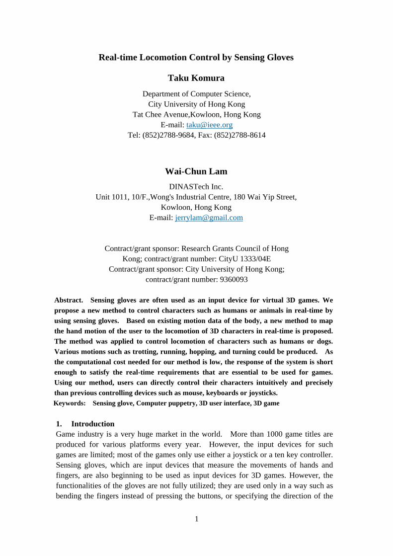
3.2 Procedure The flow chart of the procedure to control the character is shown in Figure 2. The method we propose in this research can be divided into the calibration stage and the control stage. The procedure done in each stage is as follows:
5
Figure 2. Flowchart of the processing
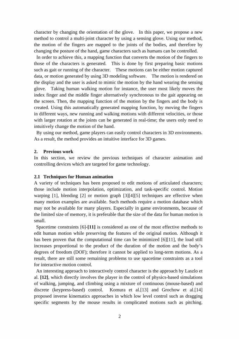
In the calibration stage, the mapping function that defines the relationship between the motion of the fingers and the character is generated. At first, the player mimics the character motion appearing on the graphical display using the hand, as shown in Figure 3. The correspondence of the finger’s generalized coordinate and those of the body are detected at this stage. Parameters such as the cycle of the motion, and the minimum/maximum output value from the sensors and the generalized coordinates of the character are also obtained. The period of each trajectory is obtained by calculating its auto-correlation value. The synchronization of the finger and character motions are done by matching the timing of the tips and pits of the motion curves. Finally, using this information, the mapping function that converts the hand motion to the human body motion is constructed.
Figure 3. Mimicking the motion appearing on the graphical display
In the control stage, the player performs a new movement by the hand; then the

6
corresponding motion of the character based on the mapping function is generated and displayed in real-time. The user can change the movement of the fingers and the wrist to reproduce similar but different motions. For example, if the original clip is a walking motion, it is possible to generate a running motion by moving the fingers quickly. The method to generate the mapping function is explained in the following section. 4. Construction of the Mapping Function As the degrees of freedom of the hand is limited comparing to that of character’s whole body, sometimes it is difficult to mimic the motion of a character with many joints. However, the user intuitively figures out the most distinctive features of the motion and tries to mimic it. A technique is introduced here to find out the correspondence of the user’s hand motion and the character’s motion. 4.1 Topological matching of the human body and the fingers The motion of hand is mapped to the motion of the character. Since the topology of the character and the hand are different, it is necessary to determine which finger motion matches to which generalized coordinate of the character’s body. In this research, we propose a method to automatically calculate this correspondence by comparing the motion of the fingers and that of the character. We assume the motions used in the calibration stage are cyclic locomotion such as walking, hopping, trotting, and running. The period of each DOF is calculated first; this can be done by calculating the auto-correlation of the trajectories:
( )( )[ ]( ) ( )∑∑∑
−−
−−=
222
211
2211
')(')(
')(')()(
SnSSnS
SnSSnSkR
where R(k) is the auto-correlation between the original trajectory S1(n) and its k- phase-shifted one S2(n) = S1(n - k), S1’ is the mean of S1(n), and S2’ is the mean of S2(n). When the value of R(k) is close to 1, then k can be considered as the cycle of the trajectory. The period of the motion of the fingers mimicking the character’s motion is estimated, respectively. The auto-correlation curve calculated out of the hip’s trajectory during walking is shown in Figure 4.
Figure 4. Auto-correlation curve of the knee flexion/extension during walking

7
We assume the shortest timeframe the autocorrelation value becomes close enough to 1 as the cycle; in the above case, it is possible to find out the cycle is 50 frames. In case of locomotion, most of the generalized coordinates of the character have a cycle same as, or half of, the user’s finger cycle mimicking the character’s locomotion. Based on this assumption, the joints are classified into the category of full cycle, half cycle, or exceptional. If the joint is classified into the exceptional category, the value of the generalized coordinates of that joint is kept constant. For example, in case of mimicking the walking motion by the index and middle finger, the joints of the legs have the same cycle as those of the fingers, and therefore they are put into the full cycle category. However, joints such as forward flexion / extension of the chest and head have a cycle that is half of those by the fingers, and they are classified to the half cycle category. After classifying the joints into the above three categories, the hand’s generalized coordinates are matched with those of the character. This matching is done based on the 3D velocity of the user’s fingers and the character’s body segments (Figure 5). In the human walking example, the character has five end effectors; the left and right hands, head, and the left and right feet.
Figure 5 Using 3D velocities to match the joints of the character with those of the hand
First, the relative velocity of the character’s end effectors comparative to the root of the body, which is the pelvis, is calculated:
)()( txtxv gc
ic
ic && −=
where )(tx gc& is the velocity of the root of the body, and )(tx i
c& is the velocity of the
i-th end effecter, and icv is the relative velocity of the i-th end effecter comparative to
the root. Next, the relative velocities of the tip of the fingers comparative to the wrist of the hand is calculated:
)()( txtxv gh
jh
jh && −=
where )(tx gk& is the velocity of the hand, and )(tx j
h& is the velocity of finger j, and jhv
is the relative velocity of the finger j comparative to the wrist. The direction of all icv

8
and jhv are compared, and all the end effectors of the character are matched with the
finger of the user; the finger that minimizes the following equation is considered as the corresponding finger:
ic
jh
ic
jh
vvvv • .
The motion of all the ancestor joints of the end effecter which are not the ancestors of any other end effectors is controlled by the finger that corresponds to the end effecter. Joints which are the ancestor of more than two end effectors are controlled by the difference of joint angle of the two fingers. A result of topologically matching the index and middle finger to the human body character for a gait motion is shown in Figure 6. Another result of matching the finger gait and the trot of the dog is shown in Figure 7.
Figure 6. The correspondence of the fingers and the joints of the human body for walking. The motion of the index finger is mapped to the left hip, left knee, and right shoulder, and the motion of the middle finger is mapped to the right hip, right knee and left shoulder.
Figure 7 The correspondence of the fingers and the joints of the dog for trotting. The motion of the index finger is mapped to the left rear leg synchronously (red line), while the right front leg is mapped with the motion of the index finger with a dynamically-changed delay (red dotted line)
4.3 Mapping the finger trajectory to the character’s joint Different mapping functions are prepared for the increment and decrement phase of the generalized coordinates. For example, if the motion of a finger is matched to the

9
motion of the knee joint, two different mapping functions are prepared for the flexion and extension period. This approach is needed as the trajectory of the joint angles of the legs tend to be asymmetric when the joints are flexed and extended as shown in Figure 8(b), where the profile of the fingers tend to be symmetric as shown in Figure 8(a). Multiple points of the trajectory of the hand motion, which are defined here by xi, and the corresponding sample points of the leg motion, defined here by yi, are obtained from the motion. Then, a 2D curve that interpolates the sampled points (xi, yi) is generated using B-spline curves. This curve is used as the mapping function when the user performs a new hand motion. Example of calculating the mapping function is shown in Figure 8(c) and (d); a mapping function that converts the trajectory of the finger joint shown in Figure 8(b) to the trajectory of the knee joint shown in Figure 8(a) is calculated. Two mapping functions are generated; one for the incremental period in Figure 8(c) and the decremental period in Figure 8(d).
Figure 8. (a). The trajectory of the finger motion, (b). the corresponding motion of the knee, (c). the mapping function between the finger motion and the knee motion in the incremental part, and (d) in the decremental part
For trajectories with half cycle, during the flexion or extension of the fingers, the character’s joints move for a full cycle. The mapping function is also generated during the calibration stage based on the trajectory of the finger and the original motion of the character. The mapping function of the index finger to the trajectory of the right knee flexion/extension and the chest flexion/extension of the human character during walking is shown in Figure 9.

10
Figure 9 A mapping function that converts the trajectory of the middle finger to that of the right hip (solid line), and that converts the difference of the index and middle finger to the flexion/extension of the chest (dotted line).
Each trajectory is split into the incremental/decremental period at the maximum (minimum) value during the cycle. Note if there are more than one pits/pins within the period, there are chances the generalized coordinates decrease during the incremental part or increase during the decremental part. Since we assume the trajectories of the fingers are monotonic during the incremental/decremental period, even in such cases, a one-to-one mapping function can be generated. 4.3 Phase shift Although the period of the fingers and the joints of the character’s match well, sometimes there is a phase shift between them. For example, when a four-legged animal such as a dog or horse trots, there is a certain delay in the motions of the fore legs and the rear legs. In Figure 10, the trajectories of the limb joints of a dog trotting is plotted. The motion of the index finger is mapped to the trajectory of the left front and right rear limb of the trotting dog, and the motion of the right finger is mapped to those of the right front and left rear limb. It is possible to observe for these pair of limbs, there is some delay between the corresponding tips and pits of the trajectories. In order to convert the user’s finger motion to the trot by the dog in real-time, it is necessary to take into account this phase shift effect.

11
(a) (b)
Figure 10. The trajectories of the joint angles of a dog’s four legs. (a) Trajectories of left rear leg (solid line) vs. right front leg (dotted line). (b) Trajectories of right rear leg (solid line) vs. left front leg (dotted line). Phase shift can be observed in both pairs.
The magnitude of the phase shift must change according to the period of the motion; for example if the dog runs faster, the delay must be shorter and if the dog walks slower, it must be longer. This can be achieved by keeping the ratio of the phase shift and the period the same when the user controls the character. The original phase shift between the finger’s motion and the character’s motion, D0, is calculated during the calibration stage. This can be done by comparing the timing of the tip / pits of the two motions. In order to dynamically change the phase shift during the motion, it is necessary to detect the cycle of the finger motion in real-time. The intermediate value of the finger data obtained in the calibration stage is used to estimate the cycle; the time lag between the timing the finger passes this intermediate value twice is considered as the current cycle of the finger motion. As the original and current cycle of the finger is defined by C0 and C1, respectively, the current phase shift D1 is calculated by
0
101 C
CDD ×= .
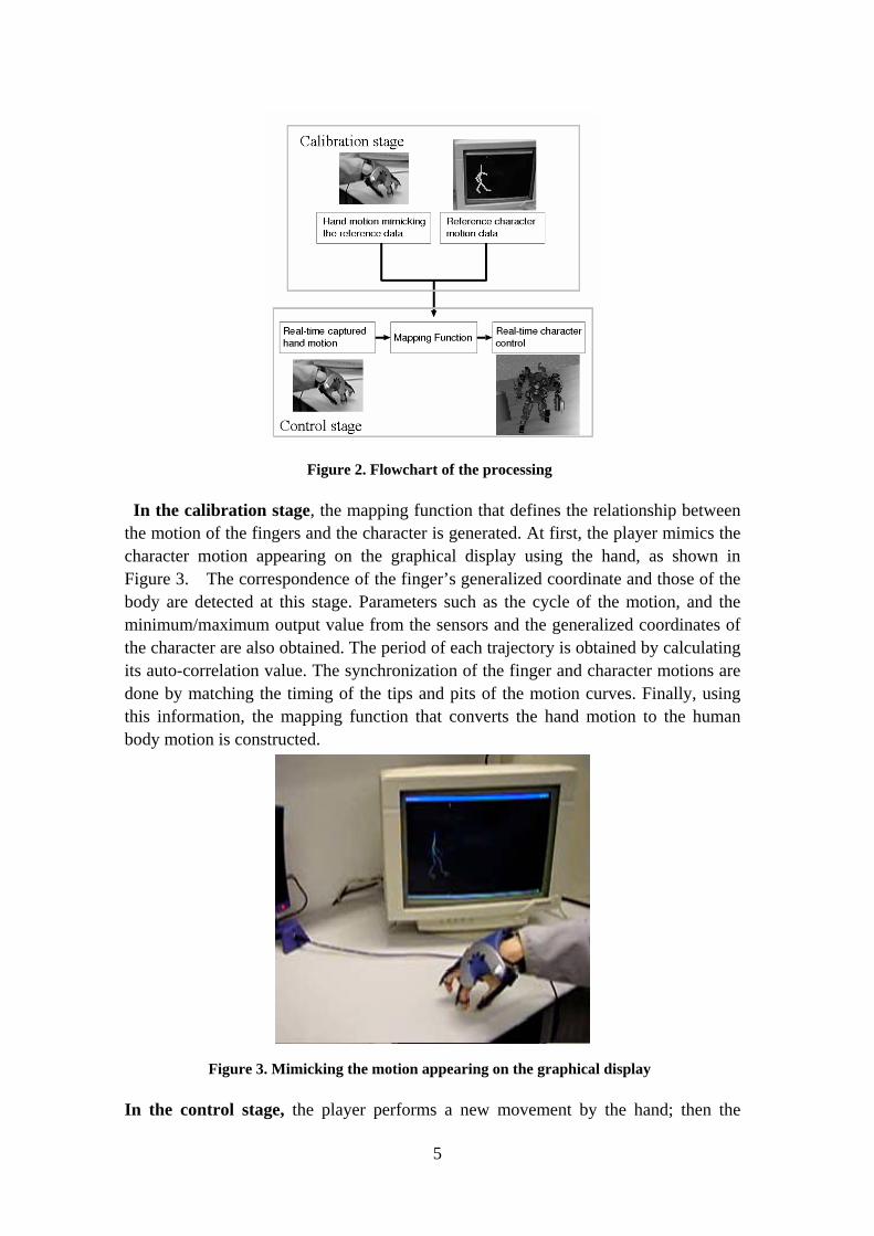
4.4 Extrapolation When a new motion is generated by the user using the sensing glove, the movements of the fingers must be mapped to the motion of the whole body using the mapping function generated in the calibration stage. However, the range of the joint angles of the fingers may vary in the new motion; for example, if the user tries to generate a running motion using a mapping function based on walking motion, the domain of the mapping function does not cover the range of the new finger motion if the user suddenly extends or flexes the fingers further. In that case, further extrapolation is done based on the tangent of the mapping function at the end of the original domain. However, to avoid extreme postures, this extrapolation is done only for a small range out of the original domain. We also set the upper and lower boundaries of the joint angles. Whenever the joint angles exceed such boundaries, the joint angles are kept the same until the value calculated by the mapping function comes back into the valid domain. 4. Experiments Experiments were conducted with two characters, the human and the dog. A motion of a human walking (Figure 11) and a dog trotting (Figure 12) were used as the basic input motion data. While these motions were shown on the screen, the user mimicked their motions using the two index and middle fingers. The topological matching of the fingers and the joints of the characters were automatically done as shown in Figure 6 and Figure 7. For the dog motion, phase shifts were also detected for the motion of the rear legs.
12
Figure 11 The original human walking motion
Figure 12 The original dog walking motion.
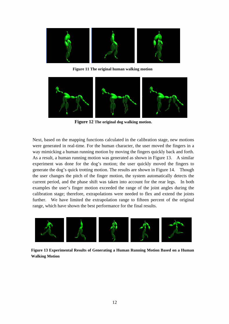
Next, based on the mapping functions calculated in the calibration stage, new motions were generated in real-time. For the human character, the user moved the fingers in a way mimicking a human running motion by moving the fingers quickly back and forth. As a result, a human running motion was generated as shown in Figure 13. A similar experiment was done for the dog’s motion; the user quickly moved the fingers to generate the dog’s quick trotting motion. The results are shown in Figure 14. Though the user changes the pitch of the finger motion, the system automatically detects the current period, and the phase shift was taken into account for the rear legs. In both examples the user’s finger motion exceeded the range of the joint angles during the calibration stage; therefore, extrapolations were needed to flex and extend the joints further. We have limited the extrapolation range to fifteen percent of the original range, which have shown the best performance for the final results.
Figure 13 Experimental Results of Generating a Human Running Motion Based on a Human Walking Motion

13
Figure 14 Experimental Results of Generating a Dog’s Running Motion Based on a Dog’s Walking Motion
Next, we have applied our method to control a robot character with the same body structure in an experimental 3D game environment. A hopping motion and a zigzag walking motion were performed by the user with the sensing glove to control the motion of a robot in 3D games in real-time.
For the hopping motion, we have used a 3D environment which requires the player to control a robot to jump over obstacles. The mission of the task was to let the robot character jump over the bouncing obstacles without touching them. During the task, the user moves the hand up and down onto the table in order to control the character to perform a few hops and at the same time avoid bars coming out from the ground. The results are shown in Figure 15.
Figure 15 Controlling a robot character to jump over obstacles
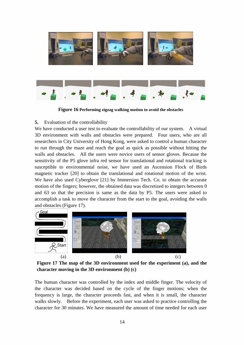
For the zigzag walking motion, another environment that requires the user to control the robot in a way it avoids obstacles while running on the plane, was prepared. The mission in this task is to let the robot walk between some boxes without touching them, then stop and fire a bullet at the end of the motion. The user controls the robot with the index and middle fingers and changes the direction of the robot by rotating the hand around the vertical axis. The results are shown in Figure 16. In both examples, intuitive control could be achieved without any special training or practice.
14
Figure 16 Performing zigzag walking motion to avoid the obstacles
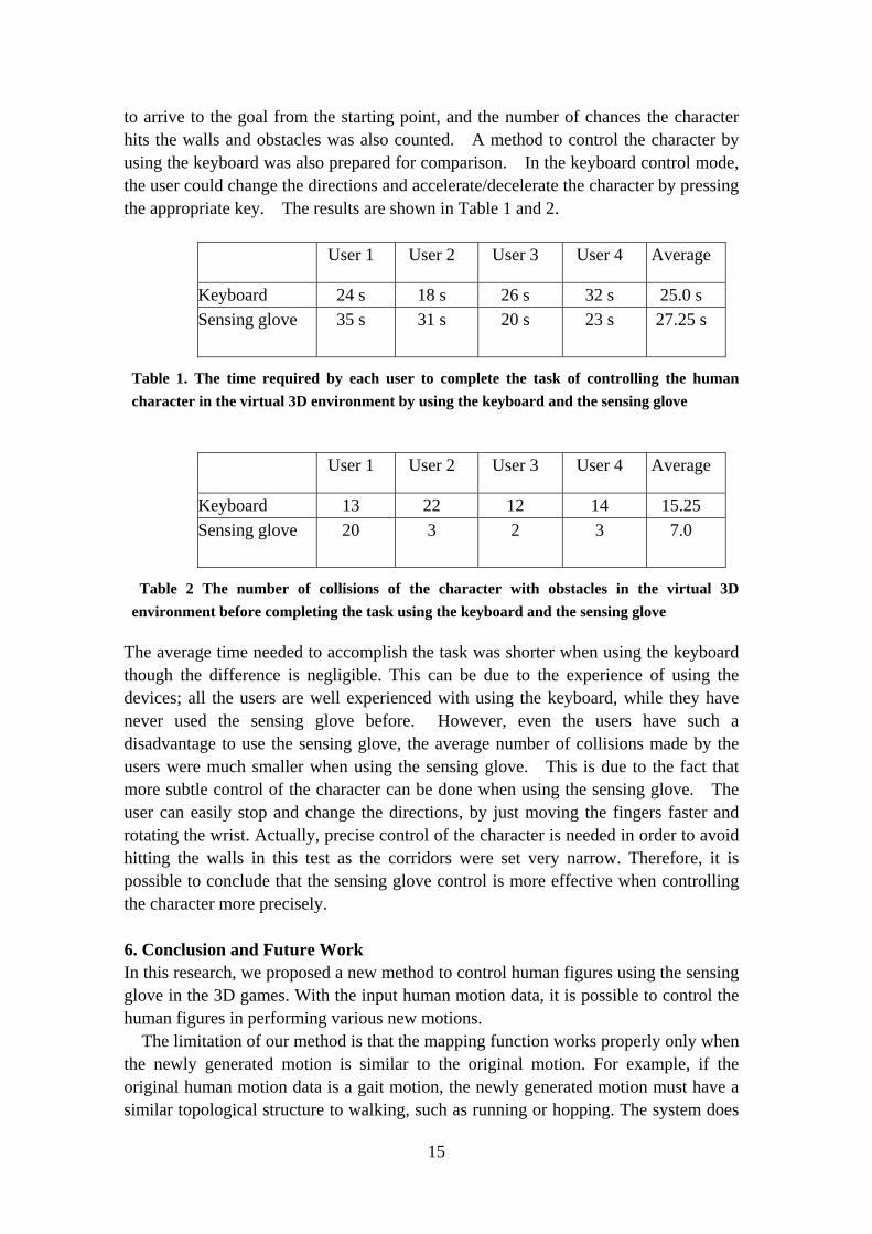
5. Evaluation of the controllability We have conducted a user test to evaluate the controllability of our system. A virtual 3D environment with walls and obstacles were prepared. Four users, who are all researchers in City University of Hong Kong, were asked to control a human character to run through the maze and reach the goal as quick as possible without hitting the walls and obstacles. All the users were novice users of sensor gloves. Because the sensitivity of the P5 glove infra red sensor for translational and rotational tracking is susceptible to environmental noise, we have used an Ascension Flock of Birds magnetic tracker [20] to obtain the translational and rotational motion of the wrist. We have also used Cyberglove [21] by Immersion Tech. Co. to obtain the accurate motion of the fingers; however, the obtained data was discretized to integers between 0 and 63 so that the precision is same as the data by P5. The users were asked to accomplish a task to move the character from the start to the goal, avoiding the walls and obstacles (Figure 17).
(a) (b) (c)
Figure 17 The map of the 3D environment used for the experiment (a), and the character moving in the 3D environment (b) (c)
The human character was controlled by the index and middle finger. The velocity of the character was decided based on the cycle of the finger motions; when the frequency is large, the character proceeds fast, and when it is small, the character walks slowly. Before the experiment, each user was asked to practice controlling the character for 30 minutes. We have measured the amount of time needed for each user
15
to arrive to the goal from the starting point, and the number of chances the character hits the walls and obstacles was also counted. A method to control the character by using the keyboard was also prepared for comparison. In the keyboard control mode, the user could change the directions and accelerate/decelerate the character by pressing the appropriate key. The results are shown in Table 1 and 2.
User 1 User 2 User 3 User 4 Average
Keyboard 24 s 18 s 26 s 32 s 25.0 s Sensing glove 35 s 31 s 20 s 23 s 27.25 s
Table 1. The time required by each user to complete the task of controlling the human character in the virtual 3D environment by using the keyboard and the sensing glove
User 1 User 2 User 3 User 4 Average
Keyboard 13 22 12 14 15.25 Sensing glove 20 3 2 3 7.0
Table 2 The number of collisions of the character with obstacles in the virtual 3D environment before completing the task using the keyboard and the sensing glove
The average time needed to accomplish the task was shorter when using the keyboard though the difference is negligible. This can be due to the experience of using the devices; all the users are well experienced with using the keyboard, while they have never used the sensing glove before. However, even the users have such a disadvantage to use the sensing glove, the average number of collisions made by the users were much smaller when using the sensing glove. This is due to the fact that more subtle control of the character can be done when using the sensing glove. The user can easily stop and change the directions, by just moving the fingers faster and rotating the wrist. Actually, precise control of the character is needed in order to avoid hitting the walls in this test as the corridors were set very narrow. Therefore, it is possible to conclude that the sensing glove control is more effective when controlling the character more precisely. 6. Conclusion and Future Work In this research, we proposed a new method to control human figures using the sensing glove in the 3D games. With the input human motion data, it is possible to control the human figures in performing various new motions. The limitation of our method is that the mapping function works properly only when the newly generated motion is similar to the original motion. For example, if the original human motion data is a gait motion, the newly generated motion must have a similar topological structure to walking, such as running or hopping. The system does

16
not work correctly if the motion is a totally different one, such as jumping up with both legs. Even though there are still problems to be overcome, the results obtained show that the hand has a high ability to control human characters and we could still generate vivid motions for the characters in a simple and intuitive way. We limited the input to a single motion data in this research; another option to improve the results is to generate the motion not only from the original motion but from the blending of several similar but different motions. For example, if we have motions such as hopping and running in addition to ordinary walking in the database, and if the system can automatically select such motions to be used for the newly generated motion when the player controls the glove in a way that is similar to such motions, then the results will have a chance to look more natural and realistic. ACKNOWLEDGEMENTS The work described in this paper was partially supported by a CERG grant from the Research Grants Council of Hong Kong (RGC Reference No.: CityU 1333/04E) and SRG grant from City University of Hong Kong (Project No.: 9360093).
Reference [1] Witkin, A., and Popovic, Z., “Motion Warping.” In Computer Graphics, In Proceedings of SIGGRAPH’95, 1995:105-108. [2] Kovar, L. and Gleicher, M., “Automated extraction and parameterization of motions in large data sets”, ACM Transactions on Graphics 2004;23(3):559-568 [3] Kovar, L., Gleicher, M. and Pighin. F. Motion graphs. ACM Transactions of Graphics 2002;21(3):473-482 [4] Lee J, Chai J, Reitsma P, Hodgins J, Pollard N. Interactive control of avatars animated with human motion data, ACM Transactions of Graphics 2002;21(3):491–500. [5] Arikan O, Forsyth D. Motion generation from examples. Proceedings of ACM Transactions of Graphics 2002; 21(3): 483–490. [6] Fang, A. C., and Pollard, N. S., “Efficient Synthesis of Physically Valid Human Motion”, ACM Transactions on Graphics 2003;22(3):417-426 [7] Gleicher, M., “Motion Editing with Spacetime Constraints.” In Proceedings of Interactive 3D Graphics ’97, 1997:139-148. [8] Gleicher, M., “Retargetting Motion to New Characters.” In Computer Graphics, In Proceedings of SIGGRAPH ’98, 1998:33-42. [9] Gleicher, M., Litwinowicz, P., “Constraint-based motion adaptation.” Jour. Visualization and Comp. Graphics 1998;9(2):65-94 [10] Popovic, Z., and Witkin, A, “Physically Based Motion Transformation.” In Proceedings of SIGGRAPH’99, 1999:11-20 [11] Safonova, A., Hodgins, J.K, Pollard, N.S., “Synthesizing physically realistic human motion in low-dimensional, behavior-specific spaces”, ACM Transactions on Graphics 2004;23(3);514-521 [12] Laszlo, J., van de Panne, M., and Fiume, E.L., 2000. “Interactive control for physically-based animation.” Proceedings of SIGGRAPH’00, 2000:201-208.

17
[13] Komura, T., Kuroda, A., Kudoh, S., Tai, C.L., Shinagawa Y., "An Inverse Kinematics Method for 3D Figures with Motion Data" Proceedings of Computer Graphics International ’03,2003:266-271 [14] Grochow,K., Martin,S.L., Hertzmann A., Popovic, Z. “Style-based inverse kinematics”, ACM Transactions on Graphics 2004;23(3):522-531 [15] Igarashi,T., Moscovich,T.,, Hughes,J.F., "Spatial Keyframing for Performance-driven Animation", in proceedings of ACM SIGGRAPH / Eurographics Symposium on Computer Animation’05, 2005:107-116 [16] Shin, H. J., Lee, J., Shin, S. Y., Gleicher, M., “Computer puppetry: An importance-based approach”, ACM Transactions on Graphics 2001;20(2):67-94 [17] Sturman, D. J., “Computer puppetry.” IEEE Computer Graphics and Applications 1998;18(1):38-45 [18] Burdea, G., 1983, “Virtual Reality Systems and Applications” [Short Course], in Electro ’93 International Conference, Edison, NJ. [19] Essential Reality P5 Glove http://www.essentialreality.com/p5_glove.asp [20] Ascension, 1998, “Flock of Birds Real-Time Motion Tracker,” company brochure, Ascention Technology Co., Burlington, VT. [21] Immersion Co., 2001, “CyberGlove”, online at http://www.immersion.com/products/3d.