Real Time Instruction Trace - Intel · Real Time Instruction Trace Real Time Instruction Trace...
73
Revision 1.05 Order Number: 332060-004 Real Time Instruction Trace Programming Reference December 2015
Transcript of Real Time Instruction Trace - Intel · Real Time Instruction Trace Real Time Instruction Trace...
Revision 1.05 Order Number: 332060-004
Real Time Instruction Trace Programming Reference December 2015

Contents-Real Time Instruction Trace
Revision 1.05 Order Number: 332060-004
Intel technologies features and benefits depend on system configuration and may require enabled hardware, software, or service activation. Learn more at intel.com, or from the OEM or retailer. No computer system can be absolutely secure. Intel does not assume any liability for lost or stolen data or systems or any damages resulting from such losses. You may not use or facilitate the use of this document in connection with any infringement or other legal analysis concerning Intel products described herein. You agree to grant Intel a non-exclusive, royalty-free license to any patent claim thereafter drafted which includes subject matter disclosed herein. No license (express or implied, by estoppel or otherwise) to any intellectual property rights is granted by this document. The products described may contain design defects or errors known as errata which may cause the product to deviate from published specifications. Current characterized errata are available on request. This document contains information on products, services and/or processes in development. All information provided here is subject to change without notice. Contact your Intel representative to obtain the latest Intel product specifications and roadmaps. Intel disclaims all express and implied warranties, including without limitation, the implied warranties of merchantability, fitness for a particular purpose, and non-infringement, as well as any warranty arising from course of performance, course of dealing, or usage in trade. Copies of documents which have an order number and are referenced in this document, or other Intel literature, may be obtained by calling 1-800-548-4725, or by visiting http://www.intel.com/design/literature.htm. Intel Atom, Intel Core, Intel and the Intel logo are trademarks of Intel Corporation in the U.S. and/or other countries. *Other names and brands may be claimed as the property of others. Copyright © 2015, Intel Corporation. All Rights Reserved.
Real Time Instruction Trace-Contents
Real Time Instruction Trace Programming Reference v1.05
December 2015
4
Table of Contents LIST OF FIGURES ...................................................................................................................................... 7
LIST OF TABLES ........................................................................................................................................ 8
REVISION HISTORY ................................................................................................................................ 9
1 INTRODUCTION ................................................................................................................................. 11
1.1 OVERVIEW .................................................................................................................................................... 11 1.2 AVAILABILITY AND USE ............................................................................................................................... 12 1.3 FEATURES AND CAPABILITIES ..................................................................................................................... 13 1.4 USING THIS SPECIFICATION ....................................................................................................................... 14
2 RTIT OPERATIONAL MODEL ......................................................................................................... 15
2.1 RTIT ENABLES ............................................................................................................................................. 15 2.1.1 Trigger Enable (TriggerEn) .......................................................................................................... 15 2.1.2 Context Enable (ContextEn) ........................................................................................................ 15 2.1.3 Filter Enable (FilterEn) ................................................................................................................... 16
2.2 CHANGE OF FLOW INSTRUCTION TRACING ................................................................................................ 16 2.2.1 Basic Blocks ....................................................................................................................................... 16 2.2.2 Direct Transfer COFI....................................................................................................................... 16 2.2.3 Indirect Transfer COFI ................................................................................................................... 17 2.2.4 Near JMP Indirect and Near Call Indirect ............................................................................... 17 2.2.5 Near RET ............................................................................................................................................. 17 2.2.6 Far Transfer COFI ............................................................................................................................ 18 2.2.7 Flow Control Packet Summary ................................................................................................... 20
2.3 TRACE OUTPUT ............................................................................................................................................. 20 2.3.1 Debug Port ......................................................................................................................................... 20 2.3.2 Output Write Behavior ................................................................................................................... 21
2.4 TRACE FILTERING ......................................................................................................................................... 21 2.4.1 Filtering by Current Privilege Level (CPL) .............................................................................. 21 2.4.2 Filter by CR3 ...................................................................................................................................... 21 2.4.3 Filtering by IP .................................................................................................................................... 22
2.5 TRACE PROGRAMMING ................................................................................................................................. 22 2.5.1 Trace Example .................................................................................................................................. 23
2.6 INTERACTION WITH OTHER COMPONENTS ................................................................................................. 23 2.6.1 System Management Mode ......................................................................................................... 23 2.6.2 Virtual Machine EXtensions .......................................................................................................... 24
3 CONFIGURATION AND CONTROL ............................................................................................... 25
3.1 ENUMERATION .............................................................................................................................................. 25 3.2 RTIT ACCESSIBILITY ................................................................................................................................... 25 3.3 CPU CONTROL AND MODEL-SPECIFIC REGISTERS ................................................................................... 25
3.3.1 General MSR notes for RTIT ........................................................................................................ 25 3.3.2 RTIT_CTL MSR .................................................................................................................................. 26
Contents-Real Time Instruction Trace
December 2015
Real Time Instruction Trace Programming Reference v1.05
5
3.3.3 RTIT_STATUS MSR .......................................................................................................................... 29 3.3.4 RTIT_CNTP MSR ............................................................................................................................... 30 3.3.5 RTIT_EVENTS MSR .......................................................................................................................... 30 3.3.6 RTIT_LIP0-3 MSR ............................................................................................................................ 31 3.3.7 RTIT_LAST_LIP MSR ....................................................................................................................... 32 3.3.8 RTIT_CR3_MATCH MSR ................................................................................................................. 32 3.3.9 RTIT_PKT_CNT MSR ....................................................................................................................... 33 3.3.10 RTIT_BASE_ADDR MSR ............................................................................................................. 34 3.3.11 RTIT_LIMIT_MASK MSR............................................................................................................. 34 3.3.12 RTIT_OFFSET MSR ....................................................................................................................... 34 3.3.13 RTIT_TNT_BUFF MSR ................................................................................................................. 35 3.3.14 RTIT_LAST_CALL_NLIP MSR .................................................................................................... 36
4 TRACE PACKETS AND DATA TYPES ........................................................................................... 37
4.1 TRACE PACKET SUMMARY ............................................................................................................................ 37 4.2 PACKET TYPES .............................................................................................................................................. 38
4.2.1 Packet Stream Boundary (PSB) ................................................................................................. 38 4.2.2 TNT Packet ......................................................................................................................................... 39 4.2.3 Target IP Packet ............................................................................................................................... 40 4.2.4 Flow Update Packet ........................................................................................................................ 45 4.2.5 Flow Update event: Buffer Overflow ........................................................................................ 46 4.2.6 Flow Update event: Packet Cycle Counter ............................................................................. 48 4.2.7 Flow Update event: Packet Generation Enable .................................................................... 48 4.2.8 Flow Update event: Packet Generation Disable ................................................................... 49 4.2.9 Flow Update event: Far Transfer ............................................................................................... 49 4.2.10 Paging Information Packet (PIP) ............................................................................................ 50 4.2.11 TraceSTOP Packet ........................................................................................................................ 50 4.2.12 Mini Time Counter (MTC) Packet ........................................................................................... 51 4.2.13 Super Time Sync (STS) Packet ............................................................................................... 52 4.2.14 Cycle Count Packet ...................................................................................................................... 53 4.2.15 Cycle Accurate Mode ................................................................................................................... 54
4.3 SYNCHRONOUS PACKETS ............................................................................................................................. 54 4.3.1 Packets sent out in various situations ..................................................................................... 55 4.3.2 Understanding Entering/Exiting Packet Enabled Region .................................................. 59
4.4 ASYNCHRONOUS PACKET GENERATION ...................................................................................................... 60
APPENDIX A: PROGRAMMING EXAMPLES .................................................................................... 61
APPENDIX B: OPERATION CONSIDERATION .............................................................................. 62
4.1 SLEEP STATES ............................................................................................................................................... 62 4.1.1 C1/Halt/Shutdown sleep state .................................................................................................... 62 4.1.2 C2 sleep state ................................................................................................................................... 62 4.1.3 C4 sleep state ................................................................................................................................... 62 4.1.4 C6 and S0i1/S0i2/S0i3 sleep state ........................................................................................... 62
4.2 RE-ENABLING RTIT .................................................................................................................................... 62 4.2.1 Re-Enabling with Same Configuration ..................................................................................... 63 4.2.2 Re-Enabling with Different Output Region ............................................................................. 63 4.2.3 Re-Enabling with Different Traced Region ............................................................................. 63
Real Time Instruction Trace-Contents
Real Time Instruction Trace Programming Reference v1.05
December 2015
6
APPENDIX C: BACKGROUND AND RELATED PROCESSOR MECHANISMS ........................ 64
4.3 EXISTING DEBUG AND PERFORMANCE MONITORING .................................................................................. 64 4.4 BREAK POINT ................................................................................................................................................ 64 4.5 LBR/LER ...................................................................................................................................................... 64 4.6 PERFORMANCE MONITORING/PEBS ........................................................................................................... 65 4.7 DS FOR BTS/PEBS .................................................................................................................................... 65 4.8 CR3 STATES................................................................................................................................................. 65 4.9 VIRTUAL MACHINE EXTENSION ................................................................................................................... 66
APPENDIX D: GLOSSARY AND REFERENCE .................................................................................. 67
4.10 GLOSSARY ................................................................................................................................................. 67 4.11 REFERENCE DOCUMENTS ......................................................................................................................... 69
APPENDIX E: ERRATA ............................................................................................................................ 70
Contents-Real Time Instruction Trace
December 2015
Real Time Instruction Trace Programming Reference v1.05
7
List of Figures FIGURE 1: REAL TIME INSTRUCTION TRACE OVERVIEW ........................................................................................ 12 FIGURE 2: RTIT PACKET HEADER LIST ................................................................................................................... 37 FIGURE 3: PACKET STREAM BOUNDARY .................................................................................................................. 39 FIGURE 4: TAKEN NOT TAKEN PACKET .................................................................................................................... 40 FIGURE 5: TARGET IP PACKET ................................................................................................................................. 40 FIGURE 6: RETURN COMPRESSION WITHOUT NESTED CALLS ................................................................................. 44 FIGURE 7: RETURN COMPRESSION WITH NESTED CALLS ........................................................................................ 45 FIGURE 8: FLOW UPDATE PACKET............................................................................................................................ 46 FIGURE 9: PAGING INFORMATION PACKET .............................................................................................................. 50 FIGURE 10: TRACESTOP PACKET ........................................................................................................................... 51 FIGURE 11: MINI TIME COUNTER PACKET .............................................................................................................. 52 FIGURE 12: SUPER TIME SYNCH PACKET ................................................................................................................ 53 FIGURE 13: CYCLE COUNT PACKET ......................................................................................................................... 53
Real Time Instruction Trace-Contents
Real Time Instruction Trace Programming Reference v1.05
December 2015
8
List of Tables TABLE 1: IP TYPE IN VARIOUS PACKETS ................................................................................................................. 19 TABLE 2: CLASSIFYING BRANCHES AND COFI ........................................................................................................ 20 TABLE 3: RTIT TRACE EXAMPLE .............................................................................................................................. 23 TABLE 4: RTIT CTL CONTROL REGISTER ............................................................................................................... 26 TABLE 5: CYCLE COUNTER ........................................................................................................................................ 30 TABLE 6: RTIT FILTER ENABLE ................................................................................................................................ 30 TABLE 7. RTIT EVENT IDS ....................................................................................................................................... 31 TABLE 8: RTIT LIP0-3 ADDRESS RANGE COMPARATORS .................................................................................... 31 TABLE 9: RTIT LAST LIP ......................................................................................................................................... 32 TABLE 10: RTIT CR3 COMPARATOR ....................................................................................................................... 32 TABLE 11: RTIT PACKET BYTES COUNTER ............................................................................................................. 33 TABLE 12: RTIT OUTPUT BASE ADDRESS .............................................................................................................. 34 TABLE 13: RTIT OUTPUT LIMIT MASK .................................................................................................................... 34 TABLE 14: RTIT OUTPUT OFFSET ........................................................................................................................... 35 TABLE 15: RTIT TNT PACKET BUFFER ................................................................................................................... 35 TABLE 16: RTIT LAST CALL NLIP .......................................................................................................................... 36 TABLE 17: TRACE PACKET ENABLING SUMMARY .................................................................................................... 38 TABLE 18: LIP COMPRESSION ................................................................................................................................. 41 TABLE 19: PACKET GENERATION UNDER DIFFERENT ENABLE CONDITIONS ........................................................ 55 TABLE 20: ASYNCHRONOUS PACKETS DESCRIPTIONS ........................................................................................... 60 TABLE 21: GLOSSARY ............................................................................................................................................... 67 TABLE 22: REFERENCES ............................................................................................................................................ 69
Contents-Real Time Instruction Trace
December 2015
Real Time Instruction Trace Programming Reference v1.05
9
Revision History
Date Revision Description February 2015 1.00 Initial Release March 2015 1.01 Added read RTIT_CTL MSR requirement June 2015 1.02 Added erratum E8. June 2015 1.03 Fix erroneous text listing RTIT_LIP1 as a limit address and
RTIT_LIP2 as a base address August 2015 1.04 Fix intro paragraph
Update RTIT_CTL.Dest bit behavior December 2015 1.05 Call out BASE & MASK behavior more clearly
Document output write ordering semantics

Real Time Instruction Trace
Revision 1.05 Order Number: 332060-004
1 Introduction This document describes the programming interface of Real Time Instruction Trace (RTIT), including trace configuration options and trace output. RTIT is available only on 3rd generation Intel® Atom™ processor (code named Silvermont)-based and 4th generation Intel Atom processor (code named Airmont)-based products, see 1.2 for details on which products are supported.
1.1 Overview In current Intel® architecture, Last Branch Record (LBR) and Branch Trace Store (BTS) features allow observance of internal CPU program flow. Branch information, i.e., the source and destination instruction pointers, can be stored in a hardware stack, or written to memory via processor support. Debug software can reproduce program flow based on the branch addresses and source code. However, the overhead of using BTS is very significant, while LBR only captures the last several branches only, both limitations that prohibit their use in real-time application debugging.
Real Time Instruction Trace (RTIT) works on the same principle as BTS and LBR. It operates in parallel to the primary processor pipeline and uses a separate output streaming mechanism that is external to the processor. This eliminates the limitations of existing debug mechanisms and allows continuous and efficient runtime application debugging.
RTIT encodes and compresses program flow information, such as branch targets, branch taken/not taken indications, and carries them to the memory subsystem in real time, avoiding the use of any processor assist methods. The memory subsystem then forwards the RTIT data out to external receivers for debug software to post-process and reconstruct program flow.
Real Time Instruction Trace
Real Time Instruction Trace Programming Reference v1.05
December 2015
12
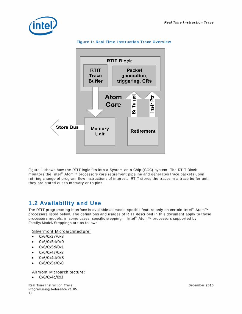
Figure 1: Real Time Instruction Trace Overview
Figure 1 shows how the RTIT logic fits into a System on a Chip (SOC) system. The RTIT Block monitors the Intel® Atom™ processors core retirement pipeline and generates trace packets upon retiring change of program flow instructions of interest. RTIT stores the traces in a trace buffer until they are stored out to memory or to pins.
1.2 Availability and Use The RTIT programming interface is available as model-specific feature only on certain Intel® Atom™ processors listed below. The definitions and usages of RTIT described in this document apply to those processors models, in some cases, specific stepping. Intel® Atom™ processors supported by Family/Model/Steppings are as follows:
Silvermont Microarchitecture: 0x6/0x37/0x8 0x6/0x5d/0x0 0x6/0x5d/0x1 0x6/0x4a/0x8 0x6/0x4d/0x8 0x6/0x5a/0x0
Airmont Microarchitecture: 0x6/0x4c/0x3
Real Time Instruction Trace
December 2015
Real Time Instruction Trace Programming Reference v1.05
13
1.3 Features and Capabilities RTIT generates a variety of packets that, along with the sources of a program, can be used to produce an exact execution trace. The packets record information such as Linear and Target Instruction Pointers (LIP and TIP) and direction of conditional branches within a contiguous code region (basic blocks). In addition the packets record other contextual, timing, and bookkeeping information to enable both functional and performance debugging of applications.
RTIT has several control and filtering capabilities to customize and compress the tracing information collected and to append other processor state and timing information to enable debugging.
Programmable address comparison registers can be used to qualify RTIT output by specifying different IP ranges and masks.
CPL and CR3 filtering modes allow filtering based on CPL execution mode (USER ring-3 or SUP ring-0) and on CR3 values.
When enabled and appropriately configured, RTIT will collect and generate the following types of trace information:
Packet stream Boundary (PSB) packets: The PSB acts as a ‘heartbeat’ that is generated at regular intervals (e.g., every 8K trace packet bytes). PSB is a unique pattern, which allows decodes to sync into a RTIT byte stream.
Taken Not Taken (TNT) packets: TNT packets track the “direction” of direct conditional branch (i.e., taken or not taken). TNT packets are 1 byte, including the header. 1 to 6 TNT (Taken-Not-Taken indications) can be packed in one TNT packet with a ‘1 signifying a taken branch and a ‘0 signifying a not-taken branch that fell through to next instruction.
Target IP (TIP) packets: TIP packets record the target IP of indirect branches, exceptions, and interrupt handlers. Up to 48 bits of IP can be stored, and the most significant bits that are identical to the branch LIP or are entirely ‘0s can be suppressed to reduce the packet size.
Flow Update (FUP) packets: FUP packets record a variety of contextual information to aid in decoding the trace output. These include:
Buffer Overflow packets (FUP.OVF) indicate that the RTIT internal buffer is full and that packets are no longer being generated.
Periodic Cycle Counter (FUP.PCC) is periodically generated based on increments in a cycle counter.
Packet Generation Enable (FUP.PGE) packets are generated when RTIT is enabled, or if the execution enters a region that is configured for RTIT tracing.
Packet Generation Disable (FUP.PGD) packets are generated when RTIT transitions from a packet generating mode into a disabled mode due to filtering criteria not being met, or disabling RTIT.
Far Transfer (FUP.FAR) packets are generated after a far transfer and will include an address indicating where the transfer came from. It is usually generated with TIP, and appears before the corresponding TIP in the trace output.
Real Time Instruction Trace
Real Time Instruction Trace Programming Reference v1.05
December 2015
14
Paging Information Packet (PIP): PIP record any modifications to the CR3 register while memory paging is enabled. This, along with process page information from the operating system, allows the debugger to attribute linear addresses to their correct application source line.
Trace STOP (STOP) packets: STOP packets are generated when the current IP matches a region specified by the ‘TraceStop’ filter.
Super Time Sync (STS) packets: STS packets are generated upon several processor frequency, power, and other state global events. They will contain the value in the processor’s HW TSC, and along with MTC are used by the debug analyzer to synchronize the traces with wall time.
Mini Time Counter (MTC) packets: MTC packets can be generated periodically based on the processor’s HW TSC, and along with STS are used by the debug analyzer to synchronize the traces with wall time.
Cycle Count Packet (CCP): CCP packets contain the incremental number of core cycles since the previous CCP, and are generated after certain other trace packets based on the configuration of the cycle accurate mode.
1.4 Using This Specification Chapter 1: Introduction gives an introduction to RTIT, where it is available, and describes the features and capabilities to customize tracing information based on user needs.
Chapter 2: RTIT Operational Model provides additional details about RTIT including the enabling and filtering, and describes essential program flow concepts that form the basis of the RTIT tracing model.
Chapter 3: Configuration and Control details the various mechanisms necessary for configuring, enabling, controlling, and collecting RTIT data in an operating system or Virtual Machine Monitor.
Chapter 4: Trace Packets and Data Types details the packets generated by RTIT to assist developers in decoding RTIT data and utilizing it to recreate an application execution trace.
Real Time Instruction Trace
December 2015
Real Time Instruction Trace Programming Reference v1.05
15
2 RTIT Operational Model This chapter describes the overall RTIT mechanism and explains essential concepts used throughout the remainder of the document. Reading this chapter will provide a basic understanding of how RTIT operates, and a detailed understanding of the various features and capabilities offered by RTIT.
This chapter is organized as follows: Section 2.1 explains the different circumstances and context during which RTIT will be generating trace packets. Section 2.2 explains the notions of flow control that are used by the RTIT mechanism to produce an execution trace. Section 2.3 describes the primary mechanism for streaming RTIT packets. Section 2.4 describes the different filters that can be used to restrict which execution streams are traced by RTIT. Section 2.5 gives an overall view of RTIT programming and provides an example of such programming. Finally, Section 2.6 describes how RTIT will behave while the processor is in non-standard execution modes.
2.1 RTIT Enables RTIT has a variety of enables and disables that interact to ultimately decide if a packet should be generated. This state is referred to as Packet Enable and is synonymous with PacketGenEnable, Packet Generation Enable or PacketEn.
When Packet Enable is set, we are in the code that RTIT is monitoring and packets are being generated to log what is being executed. PacketEn is composed of 4 other states according to this relationship:
PacketEn = TriggerEn && ContextEn && FilterEn
Each of these states is detailed in the following subsections.
2.1.1 Trigger Enable (TriggerEn)
TriggerEn (Trigger Enable) is the primary indicator that RTIT is active. TriggerEn is defined using two fields:
TriggerEn = (RTIT_CTL[Trace_En] AND RTIT_CTL[TraceActive]).
Software can get the current TriggerEn value by reading the RTIT_STATUS[TriggerEn] MSR bit. When TriggerEn is clear, RTIT is inactive and no packets are generated.
2.1.2 Context Enable (ContextEn)
Context Enable (ContextEn) indicates that the processor is in the state that RTIT is configured to watch. For example, if RTIT is configured to watch only application code (RTIT_CTL[OS]=0), then ContextEn will be 0 when the CPU is in CPL0.
Real Time Instruction Trace
Real Time Instruction Trace Programming Reference v1.05
December 2015
16
Software can get the current ContextEn value by reading the RTIT_STATUS[ContextEn] MSR bit. ContextEn is defined as follows:
ContextEn = !( (RTIT_CTL[OS]=0 AND CPL=0) OR (RTIT_CTL[USER]=0 AND CPL=1,2,3) OR (RTIT_CTL[CR3En]=1 AND RTIT_CR3_MATCH !=CR3) OR (In SMM mode) OR (In VMX mode))
When ContextEn is cleared, many packets are not generated, including all branch packets. However, some packets, such as the MTC, may still be generated while ContextEn is clear.
2.1.3 Filter Enable (FilterEn)
Filter Enable indicates that the CPU Instruction Pointer (IP) is within the range of the IPs that RTIT is configured to watch. See section 2.4.3 for details on IP filtering.
Software can get the state of Filter Enable by an MSR read of RTIT_STATUS[FilterEn].
Filter enable is only ‘usually’ correct because it may be incorrect if the RANGE0/1 ranges are not set up correctly. It is also frozen when either Trace_En or ContextEn are 0.
2.2 Change of Flow Instruction Tracing
2.2.1 Basic Blocks
A program block is a section of code where no jumps or branches occur. The IPs in this block of code need not be traced, as the CPU will execute them from start until end without redirecting code flow. Instructions such as branches, and external events such as exceptions or interrupts, can change the program flow. These instructions and events that change program flow are called COFI (Change of Flow Instructions). The program block is divided into these three categories:
Direct transfer COFI. Indirect transfer COFI. Far transfer COFI.
The following subsections describe the IA architecture COFI events that result in trace packet generation. For detailed description of the instructions, please refer to “Intel® 64 and IA-32 Architectures Software Developer’s Manual Volume 2A/2B: Instruction Set Reference.”
2.2.2 Direct Transfer COFI
These types of instructions include conditional jumps, and jumps that are to a Linear Instruction Pointer (LIP) that is embedded in the instruction bytes. It is not necessary to output the LIP of the destination address since it can be obtained through the source code. It is only necessary to indicate whether the conditional branch is taken or not.
2.2.2.1 Jump if condition is met (Jcc) and LOOP
To track this type of instruction, RTIT uses a single bit of TAKEN or NOT TAKEN (TNT) to indicate the program flow after the instruction. When the condition check is evaluated to true (i.e., the branch will
Real Time Instruction Trace
December 2015
Real Time Instruction Trace Programming Reference v1.05
17
be taken), the processor IP will update to the target IP specified in the instruction. This is encoded as TAKEN in the RTIT TNT packet; otherwise, the program will simply go to the next LIP, and is encoded in the TNT as NOT TAKEN.
Jcc and LOOP can be traced with TNT bits. To improve the trace packet output efficiency, RTIT will compact several TNT bits in a single packet. This can output up to 6 consecutive TNT bits in one TNT packet.
2.2.2.2 Unconditional Direct Jumps
There is no RTIT output for direct unconditional jumps (like JMP near relative or CALL near relative) since they can be directly inferred from the application assembly. Direct unconditional jumps do not generate a TNT bit or a Target IP packet.
2.2.3 Indirect Transfer COFI
Indirect transfer instructions involve updating the LIP from a register or memory location. Since the register or memory contents can vary at any time during execution, there is no way to know the target of the indirect transfer until the register or memory contents are read. As a result, the disassembled code cannot be used alone to determine the target of a COFI. Therefore, RTIT must send out the destination LIP in the trace packet for debug software to determine the target address of the COFI.
Indirect Transfer instructions will generate a Target IP packet (TIP) which contains the target linear address of the branch or the new instruction pointer.
2.2.4 Near JMP Indirect and Near Call Indirect
As previously mentioned, the target of an indirect COFI resides in the contents of either a register or memory location. Therefore RTIT must expose this target address to the debug software in order to determine the target of the COFI.
2.2.5 Near RET
When a CALL instruction executes, it pushes the address of the next instruction following the CALL onto the stack. Upon completion of the call procedure, the RET instruction is often used to pop the return address off of the call stack and redirect code flow back to the instruction following the call.
A RET instruction simply transfers program flow to the address it popped off the stack. Because it is possible for software to change the Extended IP (EIP) on the stack within the call procedure prior to executing the RET instruction, the debug software can be misled if it always assumes code flow will return to the instruction following the last call. Therefore, even for near RET, a Target IP Packet is sent to handle this case.
A special case is applied if the target of the RET matches the Next LIP (NLIP) of the last CALL instruction. Then only a single TNT bit of “Taken” is generated instead of a Target IP Packet.
Real Time Instruction Trace
Real Time Instruction Trace Programming Reference v1.05
December 2015
18
2.2.6 Far Transfer COFI
All operations that change the instruction pointer which are not near jumps are “far transfers”. This includes exceptions, interrupts, traps, and instructions that do far transfers (i.e. SYSENTER, SYSEXIT, SYSCALL, SYSRET, software interrupts, far jump, far call, far RET and IRET).
Far transfers that produce RTIT packets will produce a Flow Update Packet of type Far Transfer (FUP.FAR) followed by a Target IP packet (TIP); unless the far transfer also jumps out of the filtered region while keeping ContextEn==1. A far transfer that causes FilterEn to become 0 but keeps ContextEn at 1 will produce Flow Update packet of type PacketGenerationDisable (FUP.PGD instead of FUP.FAR) followed by a Target IP packet. This is a form of compression and simplifies the hardware.
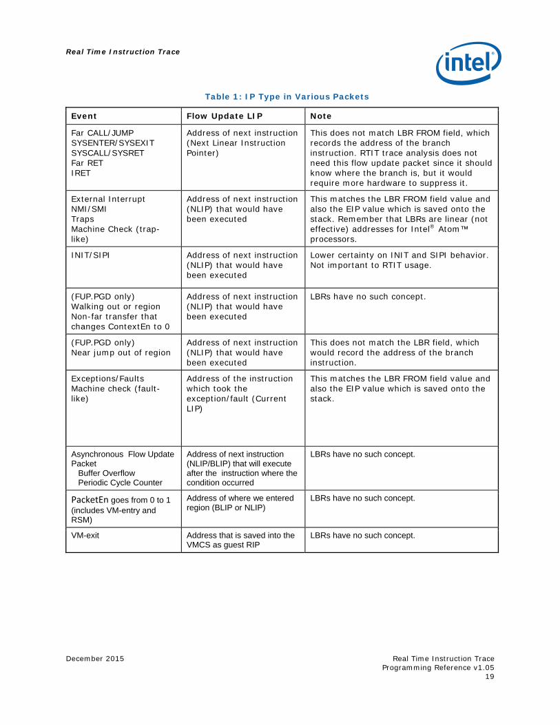
The following table indicates exactly which LIP will be included in the FUP.FAR or FUP.PGD generated by a far transfer.
Real Time Instruction Trace
December 2015
Real Time Instruction Trace Programming Reference v1.05
19
Table 1: IP Type in Various Packets
Event Flow Update LIP Note
Far CALL/JUMP SYSENTER/SYSEXIT SYSCALL/SYSRET Far RET IRET
Address of next instruction (Next Linear Instruction Pointer)
This does not match LBR FROM field, which records the address of the branch instruction. RTIT trace analysis does not need this flow update packet since it should know where the branch is, but it would require more hardware to suppress it.
External Interrupt NMI/SMI Traps Machine Check (trap-like)
Address of next instruction (NLIP) that would have been executed
This matches the LBR FROM field value and also the EIP value which is saved onto the stack. Remember that LBRs are linear (not effective) addresses for Intel® Atom™ processors.
INIT/SIPI Address of next instruction (NLIP) that would have been executed
Lower certainty on INIT and SIPI behavior. Not important to RTIT usage.
(FUP.PGD only) Walking out or region Non-far transfer that changes ContextEn to 0
Address of next instruction (NLIP) that would have been executed
LBRs have no such concept.
(FUP.PGD only) Near jump out of region
Address of next instruction (NLIP) that would have been executed
This does not match the LBR field, which would record the address of the branch instruction.
Exceptions/Faults Machine check (fault-like)
Address of the instruction which took the exception/fault (Current LIP)
This matches the LBR FROM field value and also the EIP value which is saved onto the stack.
Asynchronous Flow Update Packet Buffer Overflow Periodic Cycle Counter
Address of next instruction (NLIP/BLIP) that will execute after the instruction where the condition occurred
LBRs have no such concept.
PacketEn goes from 0 to 1 (includes VM-entry and RSM)
Address of where we entered region (BLIP or NLIP)
LBRs have no such concept.
VM-exit Address that is saved into the VMCS as guest RIP
LBRs have no such concept.
Real Time Instruction Trace
Real Time Instruction Trace Programming Reference v1.05
December 2015
20
2.2.7 Flow Control Packet Summary
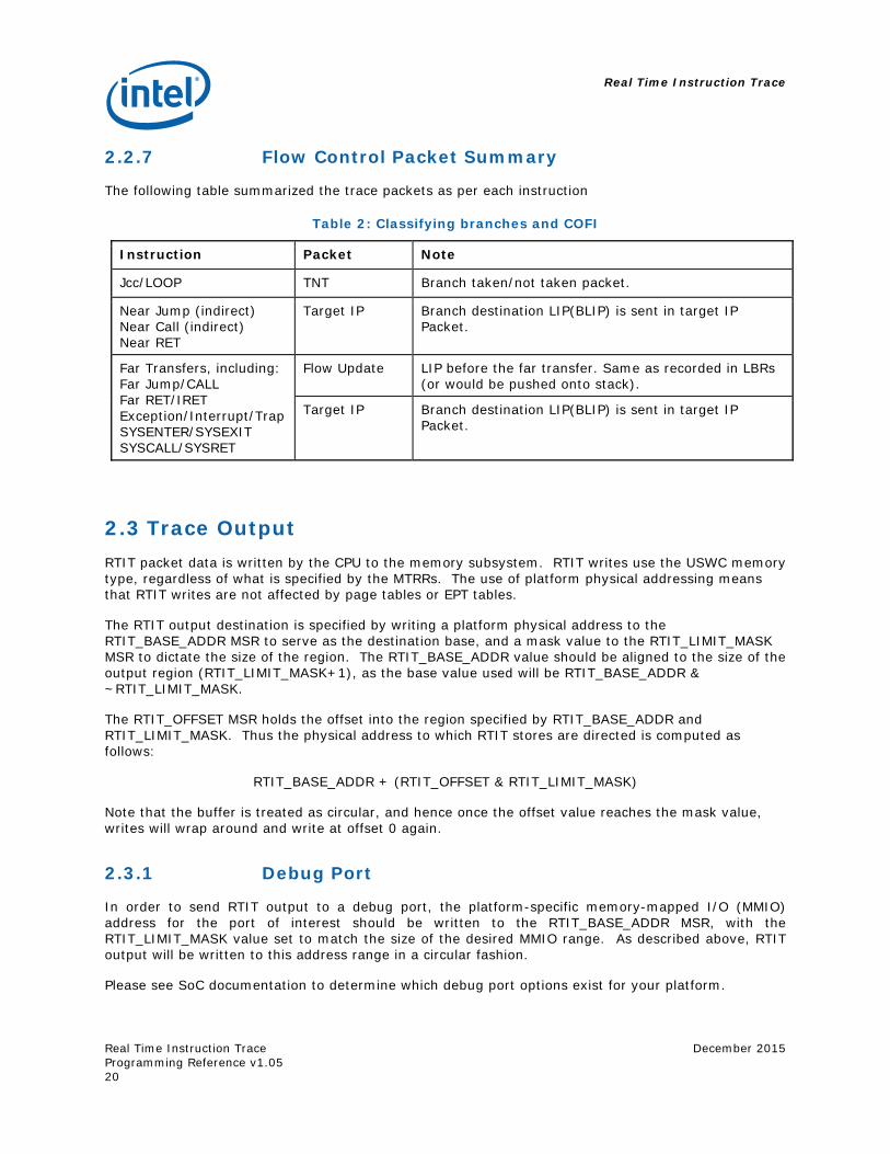
The following table summarized the trace packets as per each instruction
Table 2: Classifying branches and COFI
Instruction Packet Note
Jcc/LOOP TNT Branch taken/not taken packet.
Near Jump (indirect) Near Call (indirect) Near RET
Target IP Branch destination LIP(BLIP) is sent in target IP Packet.
Far Transfers, including: Far Jump/CALL Far RET/IRET Exception/Interrupt/Trap SYSENTER/SYSEXIT SYSCALL/SYSRET
Flow Update LIP before the far transfer. Same as recorded in LBRs (or would be pushed onto stack).
Target IP Branch destination LIP(BLIP) is sent in target IP Packet.
2.3 Trace Output RTIT packet data is written by the CPU to the memory subsystem. RTIT writes use the USWC memory type, regardless of what is specified by the MTRRs. The use of platform physical addressing means that RTIT writes are not affected by page tables or EPT tables.
The RTIT output destination is specified by writing a platform physical address to the RTIT_BASE_ADDR MSR to serve as the destination base, and a mask value to the RTIT_LIMIT_MASK MSR to dictate the size of the region. The RTIT_BASE_ADDR value should be aligned to the size of the output region (RTIT_LIMIT_MASK+1), as the base value used will be RTIT_BASE_ADDR & ~RTIT_LIMIT_MASK.
The RTIT_OFFSET MSR holds the offset into the region specified by RTIT_BASE_ADDR and RTIT_LIMIT_MASK. Thus the physical address to which RTIT stores are directed is computed as follows:
RTIT_BASE_ADDR + (RTIT_OFFSET & RTIT_LIMIT_MASK)
Note that the buffer is treated as circular, and hence once the offset value reaches the mask value, writes will wrap around and write at offset 0 again.
2.3.1 Debug Port
In order to send RTIT output to a debug port, the platform-specific memory-mapped I/O (MMIO) address for the port of interest should be written to the RTIT_BASE_ADDR MSR, with the RTIT_LIMIT_MASK value set to match the size of the desired MMIO range. As described above, RTIT output will be written to this address range in a circular fashion.
Please see SoC documentation to determine which debug port options exist for your platform.
Real Time Instruction Trace
December 2015
Real Time Instruction Trace Programming Reference v1.05
21
2.3.2 Output Write Behavior
RTIT output writes pass through the memory subsystem, and like other memory writes RTIT output is written out in 64 byte lines. In some cases, it is possible to observe partial line writes of RTIT data. This can result from enabling trace with an unaligned RTIT_OFFSET value (which would cause output to begin in the middle of the line), or from a fencing operation causing a line to be written out before it is filled (which would cause the RTIT bytes to cease before the end of the line). RTIT disable or bus locks are examples of operations that could prematurely flush an RTIT line. The implication is that it is possible to see individual RTIT writes that may include invalid bytes at the beginning and/or at the end of the line. However, as long as RTIT_OFFSET is not manipulated by software, the resulting output will be contiguous and non-overlapping.
USWC writes, like those employed by RTIT, are not strongly ordered, and thus it is possible (though rare) to observe a younger line written to its endpoint before an older line. When an RTIT drain is executed (e.g., on write to RTIT_CTL), all RTIT writes are fenced, and hence any re-ordering should have no effect on the resulting output bytes. For this reason it is recommended that collectors always disable RTIT before collecting trace output. If RTIT output is examined or collected before a drain is executed, as is typical when writes are directed to a trace hub or arbiter, the collector may need to be able to re-order any out-of-order writes. In such a case, please refer to the corresponding spec for the trace hub employed to determine the possibility of receiving out-of-order RTIT writes from the CPU.
When out-of-order RTIT writes are exposed, the degree of software re-ordering required is limited. Let us enumerate the lines comprising the output region as A, B, …, n, such that line A is the first 64-byte line in the buffer, and n is the last. Software can discern which line has been received by examining the address bits offset from the output base address in RTIT_OUTPUT_BASE. In this scenario, we’ll define an “iteration” as the sequence of writes to A..n before the output wraps back to A. Using line B as an example, it is possible that, before a given iteration of B is seen, younger lines C..n from the same iteration may be seen. It is even possible that the next iteration of A could be seen before B. However, it is not possible to first see a younger iteration of B, nor any still younger lines (e.g., next iterations of C..n).
2.4 Trace Filtering
2.4.1 Filtering by Current Privilege Level (CPL)
RTIT provides the ability to specify whether tracing occurs when code is executing in CPL0 or not. RTIT can be configured to be enabled only when in CPL0, when in CPL1/2/3, or at all CPLs. When in a non-enabled CPL, the Context Enable is cleared.
The CPL value that is used to determine the RTIT Context Enable is read after instruction retirement. This means that speculative CPL changed will not affect the RTIT state. For example, a page fault which triggers a change of CPL from 3 to 0 will not send out a TIP packet if RTIT is configured to only monitor CPL 1/2/3. A FUP packet will still be generated to indicate a traced region was left.
2.4.2 Filter by CR3
To reduce the total trace size, it is important to be able to trace a single application without requiring software intervention every time applications are switched.
Since CR3 (the page table pointer) is the primary piece of CPU state that indicates which application is running, RTIT can enable or disable tracing depending on the CR3 value. This is done through the CR3 filtering/matching feature.
Real Time Instruction Trace
Real Time Instruction Trace Programming Reference v1.05
December 2015
22
If the RTIT user desires to only trace a single CR3, then they can program that CR3 value into RTIT_CR3_MATCH MSR and set RTIT_CTL.CR3En. When the CR3 value does not match that in RTIT_CR3_MATCH, the processor will disable RTIT (ContextEn forced to 0). When the CR3 value does match of RTIT_CR3_MATCH, then the processor will stop disabling RTIT because of the CR3 value (although it could remain disabled due to other filters like CPL). If RTIT_CTL.CR3En is 0, then all CR3s are monitored (RTIT tracing is not disabled by the CR3 value).
The Paging Information Packet is sent out in various situations to explain to the analyzer which app is being executed. When a non-paging mode is entered (CR0.PG is cleared), a paging information packet is generated. This will not affect the current CR3 filtering because it is not a direct change in the value of CR3.
OS-specific techniques will need to be used to discover the CR3 value that corresponds to a particular already-running application. If the application can only be started when RTIT is already running, other techniques (like OS debug hooks, OS modification or using a special driver) may need to be used to discover the CR3 value and subsequently update the RTIT CR3 filters.
2.4.3 Filtering by IP
RTIT can be configured to enable control flow packet generation only when the CPU is executing code within certain IP ranges. This is controlled with FilterEn, which, if IP filtering is enabled, is set only when the IP is in one of the ranges specified by SW. If the IP is outside of these ranges, then FilterEn is cleared and no control flow packets are enabled.
IP filtering is enabled using the RTIT_EVENTS MSR. This MSR configures use of the RTIT_LIP[0123] MSRs, which are used to define the base and limit of the range(s) in which tracing is enabled. Current RTIT implementations have 2 such ranges, known as RANGE0 and RANGE1. RANGE0 is defined by [RTIT_LIP0..RTIT_LIP2-1], while RANGE1 is defined by [RTIT_LIP1..RTIT_LIP3-1].
EventIDs are used for IP filtering, and for TraceStop. RTIT_EVENTS[Filter Event ID] and RTIT_EVENTS[Stop Trace Event ID] are programmed with event ID encodings, which are details in section 3.3.5. Note that the Filter event ID and TraceStop event ID are two separate fields, and thus different conditions can cause those actions.
To save power, the comparison of the IP to the RANGE0/1 ranges is done only when RTIT_CTL[Trace_En] is set. This means that the FilterEn value will not be changed by the IP when Trace_En is cleared. This means that leaving Trace_En set but disabling RTIT by having Trace_Active cleared consumes more power than if Trace_En was also cleared.
It is important to note that, though no control flow packets are generated from outside of the IP filter ranges, some packets can be generated at this time. Periodic packets, such as MTC and PSB, can still be generated when FilterEn is 0.
2.5 Trace Programming RTIT provides the end-user with a highly configurable set of tracing capabilities and programmable events for both performance analysis and debug. RTIT is configured through code execution via the WRMSR and RDMSR instructions.
Real Time Instruction Trace
December 2015
Real Time Instruction Trace Programming Reference v1.05
23
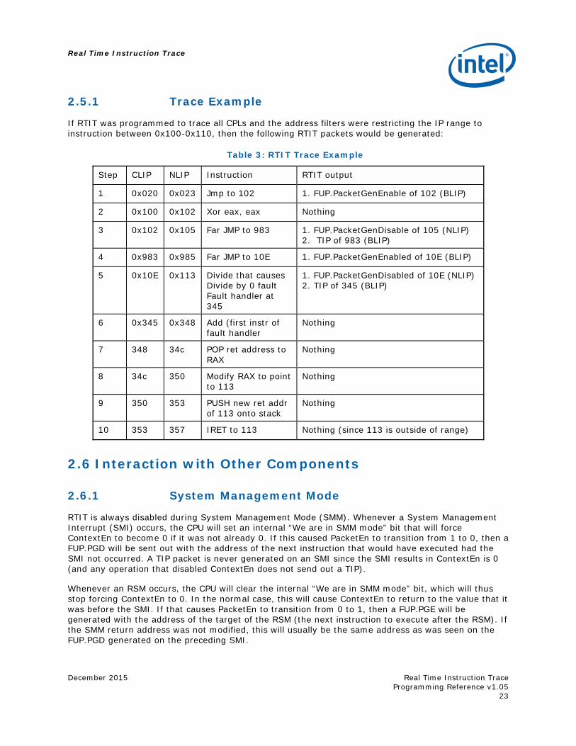
2.5.1 Trace Example
If RTIT was programmed to trace all CPLs and the address filters were restricting the IP range to instruction between 0x100-0x110, then the following RTIT packets would be generated:
Table 3: RTIT Trace Example
Step CLIP NLIP Instruction RTIT output
1 0x020 0x023 Jmp to 102 1. FUP.PacketGenEnable of 102 (BLIP)
2 0x100 0x102 Xor eax, eax Nothing
3 0x102 0x105 Far JMP to 983 1. FUP.PacketGenDisable of 105 (NLIP) 2. TIP of 983 (BLIP)
4 0x983 0x985 Far JMP to 10E 1. FUP.PacketGenEnabled of 10E (BLIP)
5 0x10E 0x113 Divide that causes Divide by 0 fault Fault handler at 345
1. FUP.PacketGenDisabled of 10E (NLIP) 2. TIP of 345 (BLIP)
6 0x345 0x348 Add (first instr of fault handler
Nothing
7 348 34c POP ret address to RAX
Nothing
8 34c 350 Modify RAX to point to 113
Nothing
9 350 353 PUSH new ret addr of 113 onto stack
Nothing
10 353 357 IRET to 113 Nothing (since 113 is outside of range)
2.6 Interaction with Other Components
2.6.1 System Management Mode
RTIT is always disabled during System Management Mode (SMM). Whenever a System Management Interrupt (SMI) occurs, the CPU will set an internal “We are in SMM mode” bit that will force ContextEn to become 0 if it was not already 0. If this caused PacketEn to transition from 1 to 0, then a FUP.PGD will be sent out with the address of the next instruction that would have executed had the SMI not occurred. A TIP packet is never generated on an SMI since the SMI results in ContextEn is 0 (and any operation that disabled ContextEn does not send out a TIP).
Whenever an RSM occurs, the CPU will clear the internal “We are in SMM mode” bit, which will thus stop forcing ContextEn to 0. In the normal case, this will cause ContextEn to return to the value that it was before the SMI. If that causes PacketEn to transition from 0 to 1, then a FUP.PGE will be generated with the address of the target of the RSM (the next instruction to execute after the RSM). If the SMM return address was not modified, this will usually be the same address as was seen on the FUP.PGD generated on the preceding SMI.
Real Time Instruction Trace
Real Time Instruction Trace Programming Reference v1.05
December 2015
24
As discussed earlier, the software SMM handler could do various things that would cause the RSM to return to a different instruction or mode than was executing before the SMI. For example, it could change the return address to be outside of the filtered region when it was inside the filtered region before the SMI. Or it could change the CR3 value.
The RSM simply clears the “We are in SMM mode” bit that was forcing ContextEn to 0. FilterEnable and the CPL will also be re-evaluated automatically based on the processor settings mode that the RSM is loading (whether it was the same as that before the SMI or not).
The RSM re-evaluates whether the CR3 matches the RTIT_CR3_MATCH MSR, and determines the SMI does not. Therefore, it is not needed on the SMI since the SMI will clear ContextEn and it cannot be set until the RSM occurs.
2.6.2 Virtual Machine EXtensions
RTIT is always disabled in Virtual Machine EXtensions (VMX) host mode (this mode is also referred to as VMM, root mode, or the hypervisor).
Whenever a VM exit occurs, the CPU will set an internal “We are in VMM mode” bit that will force ContextEn to become 0 if it was not already 0. If this caused PacketEn to transition from 1 to 0, then a FUP.PGD will be sent out with the address that is saved into the VMCS as the RIP. A TIP packet is never generated on a VM exit since the VM exit results in ContextEn of 0 (and any operation that disabled ContextEn does not send out a TIP).
Whenever a VM entry occurs, the CPU will clear the internal “We are in VMM mode” bit, which will thus stop forcing ContextEn to 0. In the normal case, this will cause ContextEn to return to the value that it was before the VM exit. If that causes PacketEn to transition from 0 to 1, then a FUP.PGE will be generated with the address of the target of the VM entry. If the VMCS guest RIP field was not modified, this will usually be the same address as was seen on the FUP.PGE generated on the preceding VM exit. VM entry will re-evaluate whether CR3 matches RTIT_CR3_MATCH.
Real Time Instruction Trace
December 2015
Real Time Instruction Trace Programming Reference v1.05
25
3 Configuration and Control This chapter details the mechanism for configuring, enabling and controlling the operation of RTIT. It is intended for developers who are writing software to support RTIT operation, whether in the OS/VMM or in the debug controller. This section can also be used as a reference for programming the relevant RTIT MSRs.
3.1 Enumeration For Intel® Atom™ processors, RTIT is not architectural and is therefore not enumerated in any way. To determine if the processor does support RTIT, the user can verify the Family, Model, and Stepping, and then use a try-accept to test for RTIT functionality.
3.2 RTIT accessibility RTIT is configured via model-specific registers (MSRs). These can be controlled through either JTAG or ring-0 software. For details about JTAG access, please contact your Intel sales representative.
3.3 CPU Control and Model-Specific Registers
3.3.1 General MSR notes for RTIT
All RTIT MSRs are described below, and are duplicated per logical processor. Until the RTIT_CTL MSR (0x768) has been read any attempt to write any RTIT MSR, or read any RTIT MSR other than RTIT_CTL, will result in a #GP fault.
For all RTIT MSRs, any MSR write that attempts to change (which usually means ‘set’) bits marked reserved will cause a #GP fault. RTIT MSRs are not cleared by INIT.
Real Time Instruction Trace
Real Time Instruction Trace Programming Reference v1.05
December 2015
26
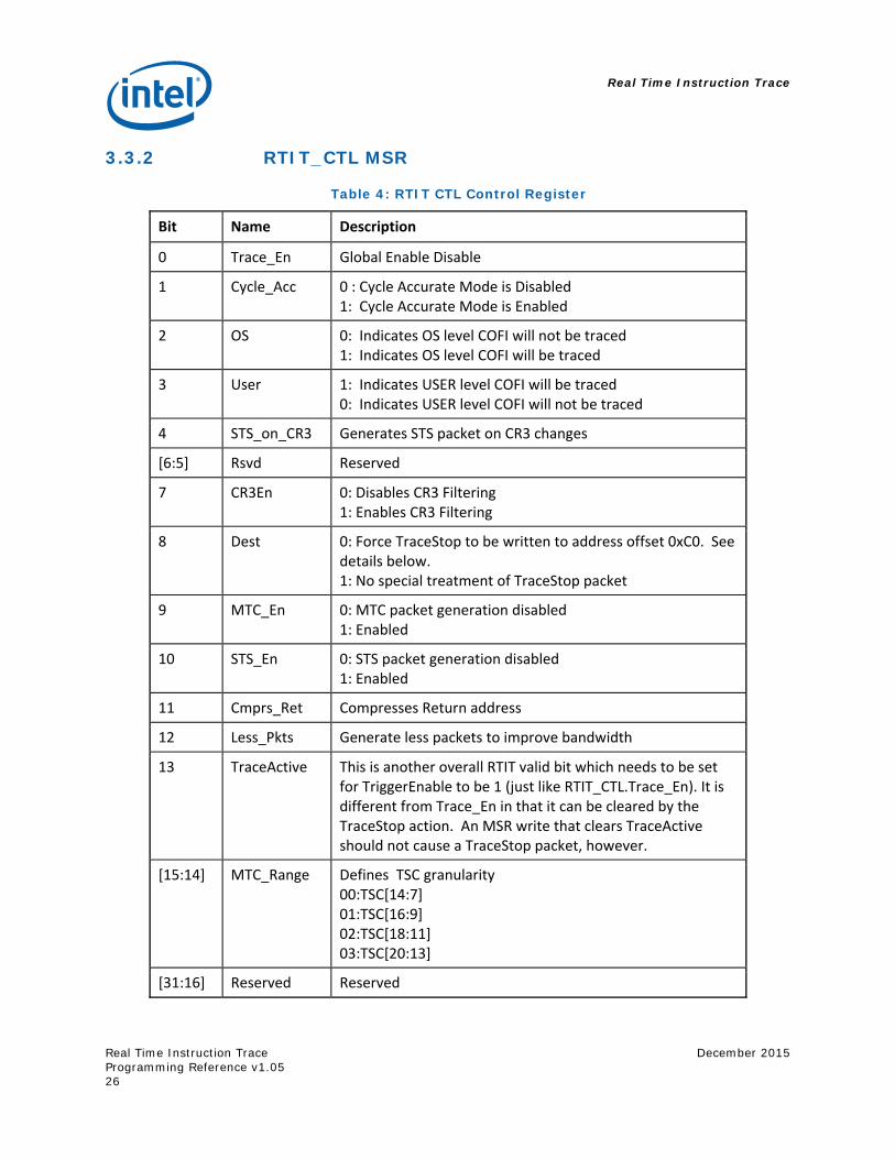
3.3.2 RTIT_CTL MSR
Table 4: RTIT CTL Control Register
Bit Name Description
0 Trace_En Global Enable Disable
1 Cycle_Acc 0 : Cycle Accurate Mode is Disabled 1: Cycle Accurate Mode is Enabled
2 OS 0: Indicates OS level COFI will not be traced 1: Indicates OS level COFI will be traced
3 User 1: Indicates USER level COFI will be traced 0: Indicates USER level COFI will not be traced
4 STS_on_CR3 Generates STS packet on CR3 changes
[6:5] Rsvd Reserved
7 CR3En 0: Disables CR3 Filtering 1: Enables CR3 Filtering
8 Dest 0: Force TraceStop to be written to address offset 0xC0. See details below. 1: No special treatment of TraceStop packet
9 MTC_En 0: MTC packet generation disabled 1: Enabled
10 STS_En 0: STS packet generation disabled 1: Enabled
11 Cmprs_Ret Compresses Return address
12 Less_Pkts Generate less packets to improve bandwidth
13 TraceActive This is another overall RTIT valid bit which needs to be set for TriggerEnable to be 1 (just like RTIT_CTL.Trace_En). It is different from Trace_En in that it can be cleared by the TraceStop action. An MSR write that clears TraceActive should not cause a TraceStop packet, however.
[15:14] MTC_Range Defines TSC granularity 00:TSC[14:7] 01:TSC[16:9] 02:TSC[18:11] 03:TSC[20:13]
[31:16] Reserved Reserved
Real Time Instruction Trace
December 2015
Real Time Instruction Trace Programming Reference v1.05
27
RTIT_CTL [0]: Trace_En
Trace_En globally turns on or off the RTIT architecture. The reset value of Trace_En is 0, disabling RTIT by default.
It is recommended that software set Trace_En before setting TraceActive (below) when enabling tracing. Similarly, software should clear TraceActive before clearing Trace_En when disabling tracing. If both Trace_En and TraceActive transition 0->1 or 1->0 in the same WRMSR, undefined behavior may result.
RTIT_CTL [1]: CYCLE_ACC
CYCLE_ACC enables or disables the cycle accurate mode of RTIT COFI tracing. When set (1’b1), a cycle count packet is appended to all outbound RTIT traffic with the exception of the PSB packet.
RTIT_CTL [2]: OS
The OS bit is used to indicate that whether CPL0 code (usually OS code) should be traced. See 2.4.1. When this bit is cleared and the current CPL is 0, then the ContextEn will be 0 (which disables many things, including COFI packets).
RTIT_CTL [3]: USER
The USER bit is used to indicate whether CPL1, CPL2, and CPL3 code (usually application code) should be traced or not. See 2.4.1. When this bit is cleared and the current CPL is 1, 2 or 3 (>0), then the ContextEn will be 0 (which disables many things including COFI packets).
RTIT_CTL [4]: STS_on_CR3
This bit being set will cause Super Time Synch Packets to be sent out on MOV CR3 operations RTIT_CTL [6:5]: Reserved.
RTIT_CTL [7]: CR3En
When this bit is set, CR3 filtering is enabled and ContextEn will be zero if the CR3 value does not matches what is in RTIT_CR3_MATCH MSR. When ContextEn is 0, COFI packets are not generated.
When this bit is cleared, the CR3 value RTIT_CR3_MATCH do not affect ContextEn. This behavior is described in more detail in the “Tracing one app (CR3 filtering)” section.
RTIT_CTL [8]: Dest
Controls treatment of the TraceStop packet. When cleared, the write of the TraceStop packet will force the lower 8 bits of the write address to 0xC0. This should only be used when RTIT output is directed to dedicated trace hardware such as PTI, on SoCs that support such specialized TraceStop treatment.
When set, there is no special treatment of the TraceStop packet. This mode supports output to DRAM, or to dedicated trace hardware such as PTI.
RTIT_CTL [9]: MTC_En
Used to enable or disable the Mini Time Counter. See Mini Time Counter (MTC) Packet section for more details.
Real Time Instruction Trace
Real Time Instruction Trace Programming Reference v1.05
December 2015
28
RTIT_CTL[10]: STS_En
Used to enable or disable Synch packet generation. A value of ‘1’ enables STS packet generation, while a value of ‘0’ disables STS packet generation.
RTIT_CTL [11]: CMPRS_RET
Setting this bit changes the behavior of indirect transfer packet generation. When set, near RET instructions may be compressed against the NLIP of the preceding call. See Indirect Transfer compression for returns (RET) section for more details.
RTIT_CTL [12]: LESS_PKTS
The LESS_PKTS bit is used to decrease the number of packets generated and thereby decrease bandwidth demands. Please refer to the following table for a complete representation of which packets are inhibited when LESS_PKTS is set. Enable Groups and Packet Generation.
RTIT_CTL [13]: TraceActive
The TraceActive bit must be set before anything in RTIT occurs because it is part of TriggerEnable. Thus when TraceActive is 0, TriggerEnable is 0 (and RTIT is off). It is cleared by TraceStop action and is settable only by an MSR write (e.g. WRMSR).
As described in the Trace_En section above, TraceActive should only be modified while Trace_En is set.
RTIT_CTL [15:14]: MTC Range
MTC Count allows the user to specify which bits of the TSC will become bit 15:8 of the MTC packet as follows:
MTC Range Resulting TSC in MTC packet 00 TSC[14:7] 01 TSC[16:9] 02 TSC[18:11] 03 TSC[20:13]
RTIT_CTL[31:16] Reserved.
MSR writes to any reserved bits results in a #GP0 fault.
MSR writes to RTIT_CTL will cause an RTIT drain and will not end until that drain is completed and all RTIT stores are globally observed. This ensures that any changes to RTIT_CTL are visible in memory by the time the MSR write completes. Thus, if software turns off RTIT by clearing TraceActive, it can count on fields like RTIT_OFFSET to be correct and constant after the MSR write.
A write to RTIT_CTL that causes RTIT_STATUS[TriggerEn] to become set (meaning that RTIT_CTL[Trace_En] and RTIT_CTL[TraceActive] are both set and one of them was not set before) will cause the PSB packet to be sent out.
An MSR write to RTIT_CTL that causes PacketEn to become 0 (e.g. by clearing OS or USR or by setting CR3En) will cause a FUP.PGD packet to be generated. An MSR write that causes PacketEn to become 0 by clearing TraceActive or Trace_En may not generate a FUP.PGD. See the FUP.PGD section for more details.
Real Time Instruction Trace
December 2015
Real Time Instruction Trace Programming Reference v1.05
29
An MSR write to RTIT_CTL that causes PacketEn to become 1 will cause a FUP.PGE packet to be sent. The MSR address is 0x768. Reset value = 0.
3.3.3 RTIT_STATUS MSR
RTIT_STATUS can be read or written by software, but some bits (like ContextEn) are read-only and cannot be modified directly. Any writes that attempt to modify these read-only bits will have no effect on the value; but will not cause a #GP (they are not checked as reserved bits).
The MSR address is 0x769. Reset value=0.
RTIT STATUS [0]: FilterEn
This is the bit that is set upon entering a tracing region and cleared upon leaving a tracing region. It indicates that the IP is within the filtered regions (but can be manipulated). It is one of the three enables that make up Packet Enable.
RTIT STATUS [1]: ContextEn
This is the context enable bit. It is set when we are in the right context for tracing (e.g. correct CPL, CR3 value, not in VMM/SMM, etc.) It is one of the three enables that make up Packet Enable. It is read-only.
RTIT STATUS [2]: TriggerEn
This is the trigger enable bit. It is set when RTIT is overall enabled (RTIT_CTL[Trace_En] AND RTIT_CTL[TraceActive]). It is one of the three enables that make up Packet Enable and is read-only.
RTIT STATUS [3]: Buffer_Overflow
This bit indicates that there is currently a buffer overflow that is pending. Under certain circumstances, software may need to context-switch that information.
It is read/write and can be updated directly by the processor or by software through MSR writes.
RTIT STATUS [31:4]: RESERVED
MSR writes to any reserved bits result in a #GP0 fault.
Real Time Instruction Trace
Real Time Instruction Trace Programming Reference v1.05
December 2015
30
3.3.4 RTIT_CNTP MSR
The MSR address is 0x76B. Reset Value: 22'b0
Table 5: Cycle Counter
Bit Name Description
[ 21 : 0 ] CNTP Count is a 22-bit incrementing counter value
[ 31 : 22] Reserved Reserved
CNTP is a 22-bit incrementing counter that counts up at a rate equal to the processor core clock. CNTP can be used to generate info on cycle count between packets in cycle accurate mode. More details of this counter are in the “Cycle Counter” section.
The counter value CNTP is reset back to 22’b0, when
CPU reset occurs (warm or cold) CNTP overflows A packet is sent out with a cycle count (the current value of CNTP). This occurs on almost
every packet sent out in Cycle Accurate mode (RTIT_CTL[Cycle_Acc]).
The RTIT hardware will attempt to send out a Periodic Cycle Count (FUP.PCC) Packet when the MSB (bit 21) of CNTP is set and it is in the appropriate mode. For more details, see the “Flow Update event: Packet Cycle Counter” section.
3.3.5 RTIT_EVENTS MSR
The MSR address is 0x76C. Reset Value: 32'b0.
Table 6: RTIT Filter Enable
Bit Name Description
[2:0] Filter_Event_ID EventID which will control RTIT_STATUS.FilterEn (Filter Enable mode bit)
[5:3] TraceStop_Event_ID EventID which will cause a TraceStop action (Stops Tracing by clearing RTIT_CTL.TraceActive)
[31:6] Reserved Reserved
RTIT_EVENTS provides a means to conditionally enable RTIT based on the user defined events.
Filter Event_ID allows the user to specify for which IPs FilterEnable should be set and for which it should be clear.
TraceStop Event_ID allows the user to specify which IPs should cause the TraceStop action. The TraceStop action stops tracing (by clearing RTIT_CTL.TraceActive it causes TriggerEn to become 0) and also causes a TraceStop packet to be generated.
Real Time Instruction Trace
December 2015
Real Time Instruction Trace Programming Reference v1.05
31
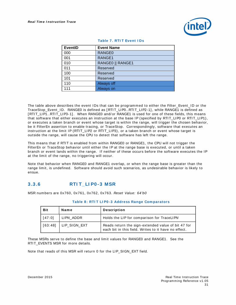
Table 7. RTIT Event IDs
EventID Event Name 000 RANGE0 001 RANGE1 010 RANGE0 || RANGE1 011 Reserved 100 Reserved 101 Reserved 110 Always off 111 Always on
The table above describes the event IDs that can be programmed to either the Filter_Event_ID or the TraceStop_Event_ID. RANGE0 is defined as [RTIT_LIP0..RTIT_LIP2-1], while RANGE1 is defined as [RTIT_LIP1..RTIT_LIP3-1]. When RANGE0 and/or RANGE1 is used for one of these fields, this means that software that either executes an instruction at the base IP (specified by RTIT_LIP0 or RTIT_LIP1), or executes a taken branch or event whose target is within the range, will trigger the chosen behavior, be it FilterEn assertion to enable tracing, or TraceStop. Correspondingly, software that executes an instruction at the limit IP (RTIT_LIP2 or RTIT_LIP3), or a taken branch or event whose target is outside the range, will cause the CPU to detect that software has left the range.
This means that if RTIT is enabled from within RANGE0 or RANGE1, the CPU will not trigger the FilterEn or TraceStop behavior until either the IP at the range base is executed, or until a taken branch or event lands within the range. If neither of these occurs before the software executes the IP at the limit of the range, no triggering will occur.
Note that behavior when RANGE0 and RANGE1 overlap, or when the range base is greater than the range limit, is undefined. Software should avoid such scenarios, as undesirable behavior is likely to ensue.
3.3.6 RTIT_LIP0-3 MSR
MSR numbers are 0x760, 0x761, 0x762, 0x763. Reset Value: 64’b0
Table 8: RTIT LIP0-3 Address Range Comparators
Bit Name Description
[47:0] LIPN_ADDR Holds the LIP for comparison for TraceLIPN
[63:48] LIP_SIGN_EXT Reads return the sign-extended value of bit 47 for each bit in this field. Writes to it have no effect.
These MSRs serve to define the base and limit values for RANGE0 and RANGE1. See the RTIT_EVENTS MSR for more details.
Note that reads of this MSR will return 0 for the LIP_SIGN_EXT field.
Real Time Instruction Trace
Real Time Instruction Trace Programming Reference v1.05
December 2015
32
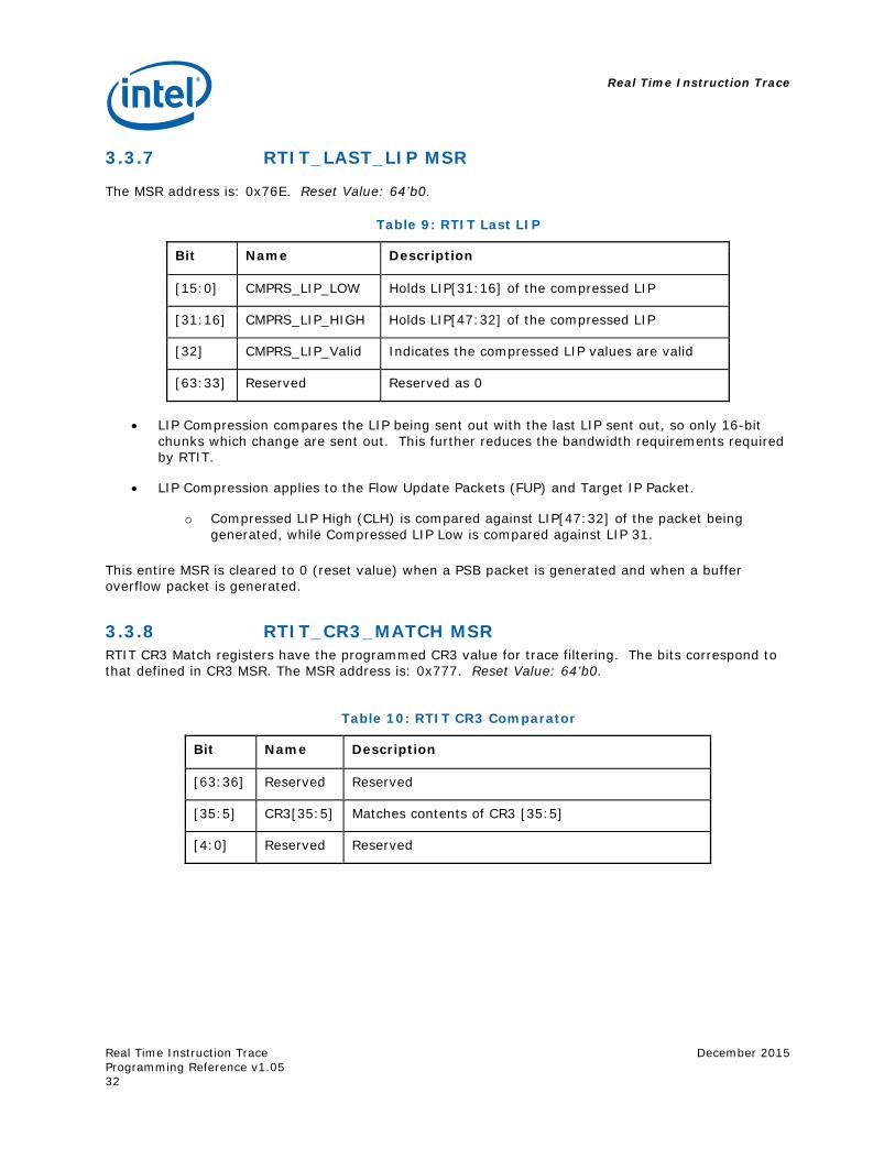
3.3.7 RTIT_LAST_LIP MSR
The MSR address is: 0x76E. Reset Value: 64’b0.
Table 9: RTIT Last LIP
Bit Name Description
[15:0] CMPRS_LIP_LOW Holds LIP[31:16] of the compressed LIP
[31:16] CMPRS_LIP_HIGH Holds LIP[47:32] of the compressed LIP
[32] CMPRS_LIP_Valid Indicates the compressed LIP values are valid
[63:33] Reserved Reserved as 0
LIP Compression compares the LIP being sent out with the last LIP sent out, so only 16-bit chunks which change are sent out. This further reduces the bandwidth requirements required by RTIT.
LIP Compression applies to the Flow Update Packets (FUP) and Target IP Packet.
o Compressed LIP High (CLH) is compared against LIP[47:32] of the packet being generated, while Compressed LIP Low is compared against LIP 31.
This entire MSR is cleared to 0 (reset value) when a PSB packet is generated and when a buffer overflow packet is generated.
3.3.8 RTIT_CR3_MATCH MSR RTIT CR3 Match registers have the programmed CR3 value for trace filtering. The bits correspond to that defined in CR3 MSR. The MSR address is: 0x777. Reset Value: 64’b0.
Table 10: RTIT CR3 Comparator
Bit Name Description
[63:36] Reserved Reserved
[35:5] CR3[35:5] Matches contents of CR3 [35:5]
[4:0] Reserved Reserved
Real Time Instruction Trace
December 2015
Real Time Instruction Trace Programming Reference v1.05
33
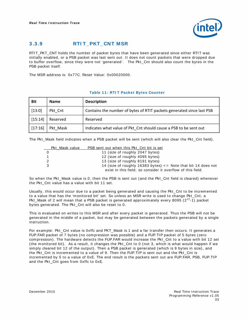
3.3.9 RTIT_PKT_CNT MSR
RTIT_PKT_CNT holds the number of packet bytes that have been generated since either RTIT was initially enabled, or a PSB packet was last sent out. It does not count packets that were dropped due to buffer overflow, since they were not ‘generated’. The Pkt_Cnt should also count the bytes in the PSB packet itself.
The MSR address is: 0x77C. Reset Value: 0x00020000.
Table 11: RTIT Packet Bytes Counter
Bit Name Description
[13:0] Pkt_Cnt Contains the number of bytes of RTIT packets generated since last PSB
[15:14] Reserved Reserved
[17:16] Pkt_Mask Indicates what value of Pkt_Cnt should cause a PSB to be sent out
The Pkt_Mask field indicates when a PSB packet will be sent (which will also clear the Pkt_Cnt field).
Pkt_Mask value PSB sent out when this Pkt_Cnt bit is set 0 11 (size of roughly 2047 bytes) 1 12 (size of roughly 4095 bytes) 2 13 (size of roughly 8191 bytes) 3 14 (size of roughly 16383 bytes) <= Note that bit 14 does not
exist in this field; so consider it overflow of this field.
So when the Pkt_Mask value is 0, then the PSB is sent out (and the Pkt_Cnt field is cleared) whenever the Pkt_Cnt value has a value with bit 11 set.
Usually, this would occur due to a packet being generated and causing the Pkt_Cnt to be incremented to a value that has the ‘monitored bit’ set. So unless an MSR write is used to change Pkt_Cnt, a Pkt_Mask of 2 will mean that a PSB packet is generated approximately every 8095 (213-1) packet bytes generated. The Pkt_Cnt will also be reset to 0.
This is evaluated on writes to this MSR and after every packet is generated. Thus the PSB will not be generated in the middle of a packet, but may be generated between the packets generated by a single instruction.
For example: Pkt_Cnt value is 0xffc and PKT_Mask is 1 and a far transfer then occurs. It generates a FUP.FAR packet of 7 bytes (no compression was possible) and a FUP.TIP packet of 5 bytes (zero compression). The hardware detects the FUP.FAR would increase the Pkt_Cnt to a value with bit 12 set (the monitored bit). As a result, it changes the Pkt_Cnt to 0 (not 3, which is what would happen if we simply cleared bit 12 of the output). Then a PSB packet is generated (which is 9 bytes in size), and the Pkt_Cnt is incremented to a value of 9. Then the FUP.TIP is sent out and the Pkt_Cnt is incremented by 5 to a value of 0xE. The end result is the packets sent out are FUP.FAR, PSB, FUP.TIP and the Pkt_Cnt goes from 0xffc to 0xE.
Real Time Instruction Trace
Real Time Instruction Trace Programming Reference v1.05
December 2015
34
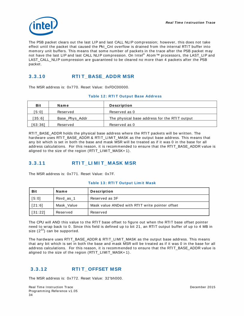
The PSB packet clears out the last LIP and last CALL NLIP compression; however, this does not take effect until the packet that caused the Pkt_Cnt overflow is drained from the internal RTIT buffer into memory unit buffers. This means that some number of packets in the trace after the PSB packet may not have the last LIP and last CALL NLIP compression. On Intel® Atom™ processors, the LAST_LIP and LAST_CALL_NLIP compression are guaranteed to be cleared no more than 4 packets after the PSB packet.
3.3.10 RTIT_BASE_ADDR MSR The MSR address is: 0x770. Reset Value: 0xFDC00000.
Table 12: RTIT Output Base Address
Bit Name Description
[5:0] Reserved Reserved as 0
[35:6] Base_Phys_Addr The physical base address for the RTIT output
[63:36] Reserved Reserved as 0
RTIT_BASE_ADDR holds the physical base address where the RTIT packets will be written. The hardware uses RTIT_BASE_ADDR & RTIT_LIMIT_MASK as the output base address. This means that any bit which is set in both the base and mask MSR will be treated as if it was 0 in the base for all address calculations. For this reason, it is recommended to ensure that the RTIT_BASE_ADDR value is aligned to the size of the region (RTIT_LIMIT_MASK+1).
3.3.11 RTIT_LIMIT_MASK MSR The MSR address is: 0x771. Reset Value: 0x7F.
Table 13: RTIT Output Limit Mask
Bit Name Description
[5:0] Rsvd_as_1 Reserved as 3F
[21:6] Mask_Value Mask value ANDed with RTIT write pointer offset
[31:22] Reserved Reserved
The CPU will AND this value to the RTIT base offset to figure out when the RTIT base offset pointer need to wrap back to 0. Since this field is defined up to bit 21, an RTIT output buffer of up to 4 MB in size (222) can be supported.
The hardware uses RTIT_BASE_ADDR & RTIT_LIMIT_MASK as the output base address. This means that any bit which is set in both the base and mask MSR will be treated as if it was 0 in the base for all address calculations. For this reason, it is recommended to ensure that the RTIT_BASE_ADDR value is aligned to the size of the region (RTIT_LIMIT_MASK+1).
3.3.12 RTIT_OFFSET MSR
The MSR address is: 0x772. Reset Value: 32’bh000.
Real Time Instruction Trace
December 2015
Real Time Instruction Trace Programming Reference v1.05
35
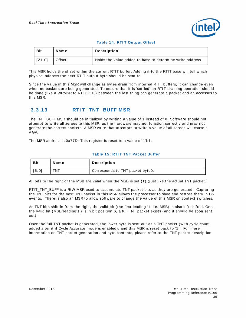
Table 14: RTIT Output Offset
Bit Name Description
[21:0] Offset Holds the value added to base to determine write address
This MSR holds the offset within the current RTIT buffer. Adding it to the RTIT base will tell which physical address the next RTIT output byte should be sent to.
Since the value in this MSR will change as bytes drain from internal RTIT buffers, it can change even when no packets are being generated. To ensure that it is ‘settled’ an RTIT-draining operation should be done (like a WRMSR to RTIT_CTL) between the last thing can generate a packet and an accesses to this MSR.
3.3.13 RTIT_TNT_BUFF MSR
The TNT_BUFF MSR should be initialized by writing a value of 1 instead of 0. Software should not attempt to write all zeroes to this MSR, as the hardware may not function correctly and may not generate the correct packets. A MSR write that attempts to write a value of all zeroes will cause a #GP.
The MSR address is 0x77D. This register is reset to a value of 1’b1.
Table 15: RTIT TNT Packet Buffer
Bit Name Description
[6:0] TNT Corresponds to TNT packet byte0.
All bits to the right of the MSB are valid when the MSB is set (1) (just like the actual TNT packet.)
RTIT_TNT_BUFF is a R/W MSR used to accumulate TNT packet bits as they are generated. Capturing the TNT bits for the next TNT packet in this MSR allows the processor to save and restore them in C6 events. There is also an MSR to allow software to change the value of this MSR on context switches.
As TNT bits shift in from the right, the valid bit (the first leading ‘1’ i.e. MSB) is also left shifted. Once the valid bit (MSB/leading’1’) is in bit position 6, a full TNT packet exists (and it should be soon sent out).
Once the full TNT packet is generated, the lower byte is sent out as a TNT packet (with cycle count added after it if Cycle Accurate mode is enabled), and this MSR is reset back to ‘1’. For more information on TNT packet generation and byte contents, please refer to the TNT packet description.

Real Time Instruction Trace
Real Time Instruction Trace Programming Reference v1.05
December 2015
36
3.3.14 RTIT_LAST_CALL_NLIP MSR
MSR write will cause a #GP on any attempt to set a reserved bit.
The MSR address is 0x76F. Reset Value: 32’bh000.
Table 16: RTIT Last Call NLIP
Bit Name Description
[31:0] Call_NLIP[31:0] Stores the NLIP[31:0] of the last Call Instruction
[47:32] Call_NLIP[47:32] Stores the NLIP [47:32] of the last Call Instruction
48 NLIP_Valid The stored NLIP[47:0] is valid
The RTIT_LAST_CALL_NLIP registers are used to store the NLIP of the last call retired. This is used for compressing the packet generation of indirect call/returns. For more details on the underlying architecture and a description of return compression please refer to the indirect transfer compression for returns section: “Indirect Transfer compression for returns (RET)”.
This entire MSR is cleared to 0 (reset value) when a PSB packet is generated and when a buffer overflow packet is generated.
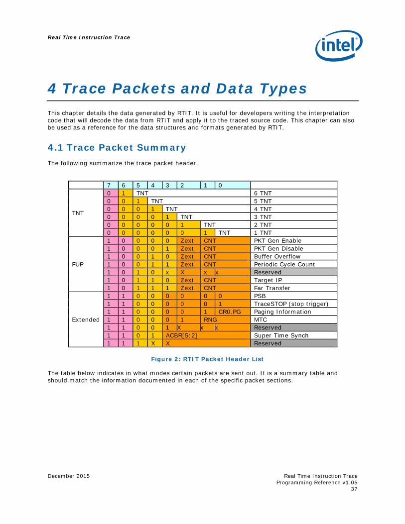
Real Time Instruction Trace
December 2015
Real Time Instruction Trace Programming Reference v1.05
37
4 Trace Packets and Data Types This chapter details the data generated by RTIT. It is useful for developers writing the interpretation code that will decode the data from RTIT and apply it to the traced source code. This chapter can also be used as a reference for the data structures and formats generated by RTIT.
4.1 Trace Packet Summary The following summarize the trace packet header.
7 6 5 4 3 2 1 0
TNT
0 1 TNT 6 TNT 0 0 1 TNT 5 TNT 0 0 0 1 TNT 4 TNT 0 0 0 0 1 TNT 3 TNT 0 0 0 0 0 1 TNT 2 TNT 0 0 0 0 0 0 1 TNT 1 TNT
FUP
1 0 0 0 0 Zext CNT PKT Gen Enable 1 0 0 0 1 Zext CNT PKT Gen Disable 1 0 0 1 0 Zext CNT Buffer Overflow 1 0 0 1 1 Zext CNT Periodic Cycle Count 1 0 1 0 x X x x Reserved 1 0 1 1 0 Zext CNT Target IP 1 0 1 1 1 Zext CNT Far Transfer
Extended
1 1 0 0 0 0 0 0 PSB 1 1 0 0 0 0 0 1 TraceSTOP (stop trigger) 1 1 0 0 0 0 1 CR0.PG Paging Information 1 1 0 0 0 1 RNG MTC 1 1 0 0 1 X x x Reserved 1 1 0 1 ACBR[5:2] Super Time Synch 1 1 1 X X Reserved
Figure 2: RTIT Packet Header List
The table below indicates in what modes certain packets are sent out. It is a summary table and should match the information documented in each of the specific packet sections.
Real Time Instruction Trace
Real Time Instruction Trace Programming Reference v1.05
December 2015
38
Table 17: Trace Packet Enabling Summary
Packet When enabled
“Branch packets” - TNT, TIP, FUP.Far Transfer, TriggerEn && ContextEn && FilterEn
FUP.PacketGenEn TriggerEn && ContextEn && FilterEn
FUP.PacketGenDis TriggerEn
TraceStop Clearing of TriggerEn
Packet Stream Buffer TriggerEn
Super Time Synch and Mini-Time Counter with RTIT_CTL[LESS_PKTS] set
TriggerEn && ContextEn && FilterEn
Super Time Synch and Mini-Time Counter with RTIT_CTL[LESS_PKTS] clear
TriggerEn
FUP.PCC with RTIT_CTL[LESS_PKTS] set TriggerEn && ContextEn && FilterEn
FUP.PCC with RTIT_CTL[LESS_PKTS] clear TriggerEn && ContextEn
FUP.Buffer Overflow TriggerEn && ContextEn
Cycle Counter incrementing with RTIT_CTL[LESS_PKTS] set TriggerEn && ContextEn
Cycle Counter incrementing with RTIT_CTL[LESS_PKTS] clear TriggerEn && ContextEn && FilterEn
4.2 Packet Types
4.2.1 Packet Stream Boundary (PSB)
A PSB packet is for trace simulation software to identify a trace stream boundary. The trace packet output port size is not aligned to a trace packet word width, and the packets are written circularly into the external debugger trace buffer; it cannot be determined whether the data stream carries a valid trace packet, or just junk data.
A PSB packet consists of header 8’b1100_0000, and 8 contiguous bytes of 0, clearly indicating the packet stream boundary.
The bytes of zeroes in PSB should be more than the largest possible trace packet payload that might contain zeroes. So far, the injected packet can have up to 7 bytes of 0s, hence we put the PSB payload to be 8 bytes.
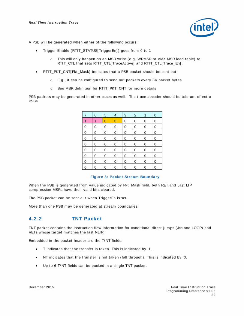
Real Time Instruction Trace
December 2015
Real Time Instruction Trace Programming Reference v1.05
39
A PSB will be generated when either of the following occurs:
Trigger Enable (RTIT_STATUS[TriggerEn]) goes from 0 to 1
o This will only happen on an MSR write (e.g. WRMSR or VMX MSR load table) to RTIT_CTL that sets RTIT_CTL[TraceActive] and RTIT_CTL[Trace_En].
RTIT_PKT_CNT[Pkt_Mask] indicates that a PSB packet should be sent out
o E.g., it can be configured to send out packets every 8K packet bytes.
o See MSR definition for RTIT_PKT_CNT for more details
PSB packets may be generated in other cases as well. The trace decoder should be tolerant of extra PSBs.
7 6 5 4 3 2 1 0 1 1 0 0 0 0 0 0 0 0 0 0 0 0 0 0 0 0 0 0 0 0 0 0 0 0 0 0 0 0 0 0 0 0 0 0 0 0 0 0 0 0 0 0 0 0 0 0 0 0 0 0 0 0 0 0 0 0 0 0 0 0 0 0 0 0 0 0 0 0 0 0
Figure 3: Packet Stream Boundary
When the PSB is generated from value indicated by Pkt_Mask field, both RET and Last LIP compression MSRs have their valid bits cleared.
The PSB packet can be sent out when TriggerEn is set.
More than one PSB may be generated at stream boundaries.
4.2.2 TNT Packet
TNT packet contains the instruction flow information for conditional direct jumps (Jcc and LOOP) and RETs whose target matches the last NLIP.
Embedded in the packet header are the T/NT fields:
T indicates that the transfer is taken. This is indicated by ‘1.
NT indicates that the transfer is not taken (fall through). This is indicated by ‘0.
Up to 6 T/NT fields can be packed in a single TNT packet.
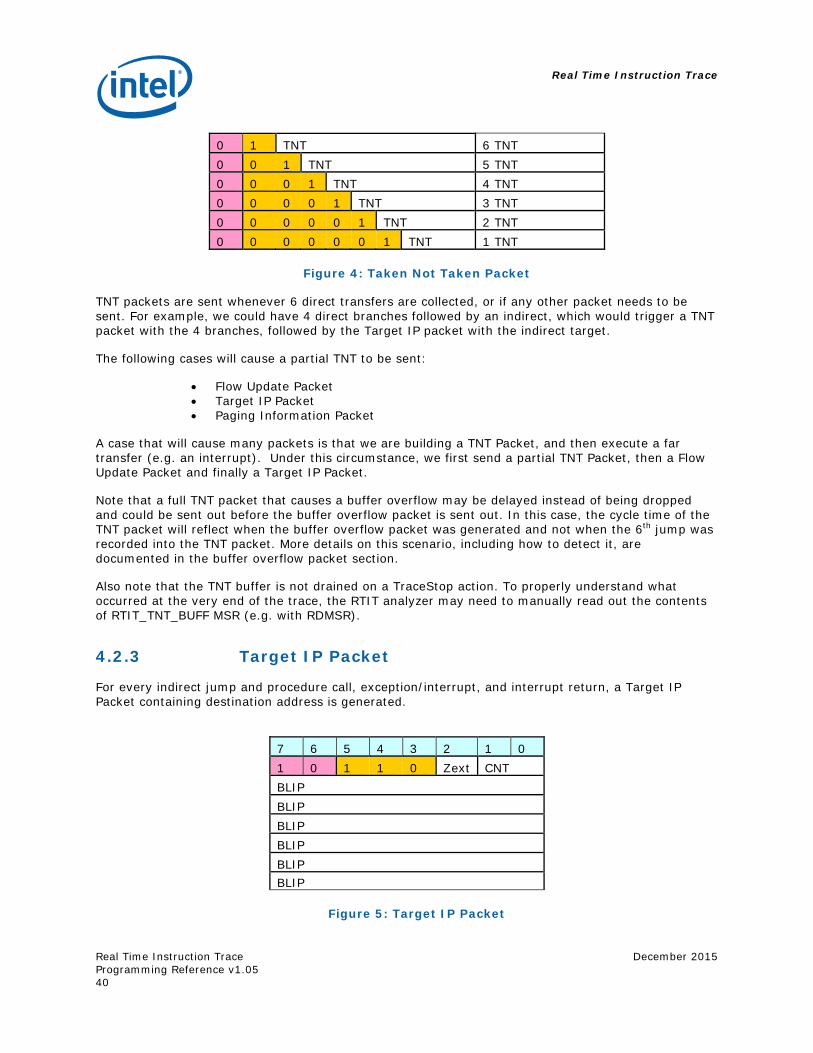
Real Time Instruction Trace
Real Time Instruction Trace Programming Reference v1.05
December 2015
40
0 1 TNT 6 TNT 0 0 1 TNT 5 TNT 0 0 0 1 TNT 4 TNT 0 0 0 0 1 TNT 3 TNT 0 0 0 0 0 1 TNT 2 TNT 0 0 0 0 0 0 1 TNT 1 TNT
Figure 4: Taken Not Taken Packet
TNT packets are sent whenever 6 direct transfers are collected, or if any other packet needs to be sent. For example, we could have 4 direct branches followed by an indirect, which would trigger a TNT packet with the 4 branches, followed by the Target IP packet with the indirect target.
The following cases will cause a partial TNT to be sent:
Flow Update Packet Target IP Packet Paging Information Packet
A case that will cause many packets is that we are building a TNT Packet, and then execute a far transfer (e.g. an interrupt). Under this circumstance, we first send a partial TNT Packet, then a Flow Update Packet and finally a Target IP Packet.
Note that a full TNT packet that causes a buffer overflow may be delayed instead of being dropped and could be sent out before the buffer overflow packet is sent out. In this case, the cycle time of the TNT packet will reflect when the buffer overflow packet was generated and not when the 6th jump was recorded into the TNT packet. More details on this scenario, including how to detect it, are documented in the buffer overflow packet section.
Also note that the TNT buffer is not drained on a TraceStop action. To properly understand what occurred at the very end of the trace, the RTIT analyzer may need to manually read out the contents of RTIT_TNT_BUFF MSR (e.g. with RDMSR).
4.2.3 Target IP Packet
For every indirect jump and procedure call, exception/interrupt, and interrupt return, a Target IP Packet containing destination address is generated.
7 6 5 4 3 2 1 0 1 0 1 1 0 Zext CNT BLIP BLIP BLIP BLIP BLIP BLIP
Figure 5: Target IP Packet
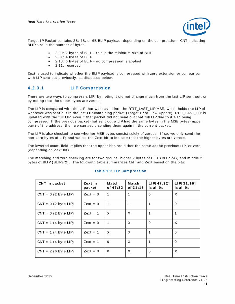
Real Time Instruction Trace
December 2015
Real Time Instruction Trace Programming Reference v1.05
41
Target IP Packet contains 2B, 4B, or 6B BLIP payload, depending on the compression. CNT indicating BLIP size in the number of bytes:
2’00: 2 bytes of BLIP - this is the minimum size of BLIP 2’01: 4 bytes of BLIP 2’10: 6 bytes of BLIP - no compression is applied 2’11: reserved
Zext is used to indicate whether the BLIP payload is compressed with zero extension or comparison with LIP sent out previously, as discussed below.
4.2.3.1 LIP Compression
There are two ways to compress a LIP: by noting it did not change much from the last LIP sent out, or by noting that the upper bytes are zeroes.
The LIP is compared with the LIP that was saved into the RTIT_LAST_LIP MSR, which holds the LIP of whatever was sent out in the last LIP-containing packet (Target IP or Flow Update). RTIT_LAST_LIP is updated with the full LIP, even if that packet did not send out that full LIP due to it also being compressed. If the previous packet that sent out a LIP had the same bytes in the MSB bytes (upper part) of the address, then we can avoid sending them again in the current packet.
The LIP is also checked to see whether MSB bytes consist solely of zeroes. If so, we only send the non-zero bytes of LIP; and we set the Zext bit to indicate that the higher bytes are zeroes.
The lowered count field implies that the upper bits are either the same as the previous LIP, or zero (depending on Zext bit).
The matching and zero checking are for two groups: higher 2 bytes of BLIP (BLIP5/4), and middle 2 bytes of BLIP (BLIP3/2). The following table summarizes CNT and Zext based on the bits:
Table 18: LIP Compression
CNT in packet Zext in packet
Match of 47:32
Match of 31:16
LIP[47:32] is all 0s
LIP[31:16] is all 0s
CNT = 0 (2 byte LIP) Zext = 0 1 1 0 X
CNT = 0 (2 byte LIP) Zext = 0 1 1 1 0
CNT = 0 (2 byte LIP) Zext = 1 X X 1 1
CNT = 1 (4 byte LIP) Zext = 0 1 0 0 X
CNT = 1 (4 byte LIP) Zext = 1 X 0 1 0
CNT = 1 (4 byte LIP) Zext = 1 0 X 1 0
CNT = 2 (6 byte LIP) Zext = 0 0 X 0 X
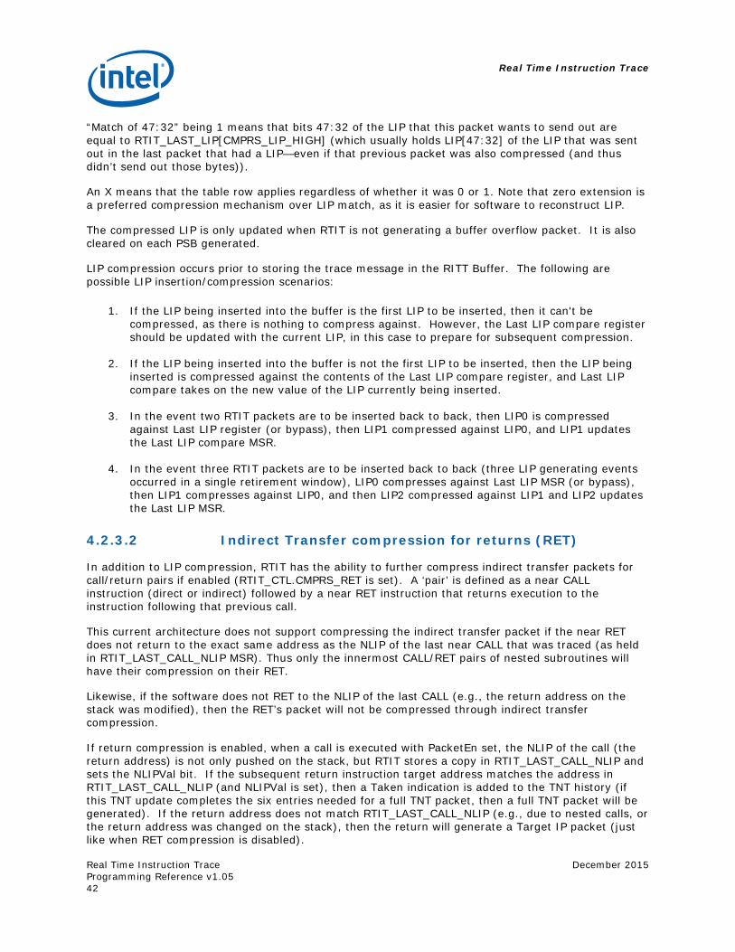
Real Time Instruction Trace
Real Time Instruction Trace Programming Reference v1.05
December 2015
42
“Match of 47:32” being 1 means that bits 47:32 of the LIP that this packet wants to send out are equal to RTIT_LAST_LIP[CMPRS_LIP_HIGH] (which usually holds LIP[47:32] of the LIP that was sent out in the last packet that had a LIP—even if that previous packet was also compressed (and thus didn’t send out those bytes)).
An X means that the table row applies regardless of whether it was 0 or 1. Note that zero extension is a preferred compression mechanism over LIP match, as it is easier for software to reconstruct LIP.
The compressed LIP is only updated when RTIT is not generating a buffer overflow packet. It is also cleared on each PSB generated.
LIP compression occurs prior to storing the trace message in the RITT Buffer. The following are possible LIP insertion/compression scenarios:
1. If the LIP being inserted into the buffer is the first LIP to be inserted, then it can't be
compressed, as there is nothing to compress against. However, the Last LIP compare register should be updated with the current LIP, in this case to prepare for subsequent compression.
2. If the LIP being inserted into the buffer is not the first LIP to be inserted, then the LIP being
inserted is compressed against the contents of the Last LIP compare register, and Last LIP compare takes on the new value of the LIP currently being inserted.
3. In the event two RTIT packets are to be inserted back to back, then LIP0 is compressed
against Last LIP register (or bypass), then LIP1 compressed against LIP0, and LIP1 updates the Last LIP compare MSR.
4. In the event three RTIT packets are to be inserted back to back (three LIP generating events
occurred in a single retirement window), LIP0 compresses against Last LIP MSR (or bypass), then LIP1 compresses against LIP0, and then LIP2 compressed against LIP1 and LIP2 updates the Last LIP MSR.
4.2.3.2 Indirect Transfer compression for returns (RET)
In addition to LIP compression, RTIT has the ability to further compress indirect transfer packets for call/return pairs if enabled (RTIT_CTL.CMPRS_RET is set). A ‘pair’ is defined as a near CALL instruction (direct or indirect) followed by a near RET instruction that returns execution to the instruction following that previous call.
This current architecture does not support compressing the indirect transfer packet if the near RET does not return to the exact same address as the NLIP of the last near CALL that was traced (as held in RTIT_LAST_CALL_NLIP MSR). Thus only the innermost CALL/RET pairs of nested subroutines will have their compression on their RET.
Likewise, if the software does not RET to the NLIP of the last CALL (e.g., the return address on the stack was modified), then the RET’s packet will not be compressed through indirect transfer compression.
If return compression is enabled, when a call is executed with PacketEn set, the NLIP of the call (the return address) is not only pushed on the stack, but RTIT stores a copy in RTIT_LAST_CALL_NLIP and sets the NLIPVal bit. If the subsequent return instruction target address matches the address in RTIT_LAST_CALL_NLIP (and NLIPVal is set), then a Taken indication is added to the TNT history (if this TNT update completes the six entries needed for a full TNT packet, then a full TNT packet will be generated). If the return address does not match RTIT_LAST_CALL_NLIP (e.g., due to nested calls, or the return address was changed on the stack), then the return will generate a Target IP packet (just like when RET compression is disabled).
Real Time Instruction Trace
December 2015
Real Time Instruction Trace Programming Reference v1.05
43
A RET instruction whose RTIT output is compressed (it only updates TNT buffer instead of sending out a TIP) will not update RTIT_LAST_LIP MSR. Architecturally, it would be fine either way, but this is the current plan.
Only near call instructions that start with PacketEn set will modify RTIT_LAST_CALL_NLIP. So near call which is within the filtered region and has PacketEn of 1 but jumps outside the filter region will still modify RTIT_LAST_CALL_NLIP with its NLIP.
A call instruction that does not start with PacketEn set and RTIT_CTL[CMPRS_RET] set will not write its NLIP into RTIT_LAST_CALL_NLIP. So a call whose CLIP is outside the filter enable region (and thus packet_en is 0) will not modify RTIT_LAST_CALL_NLIP, even if the call’s target or NLIP is within the filter enable region.
Far calls will also not modify RTIT_LAST_CALL_NLIP.
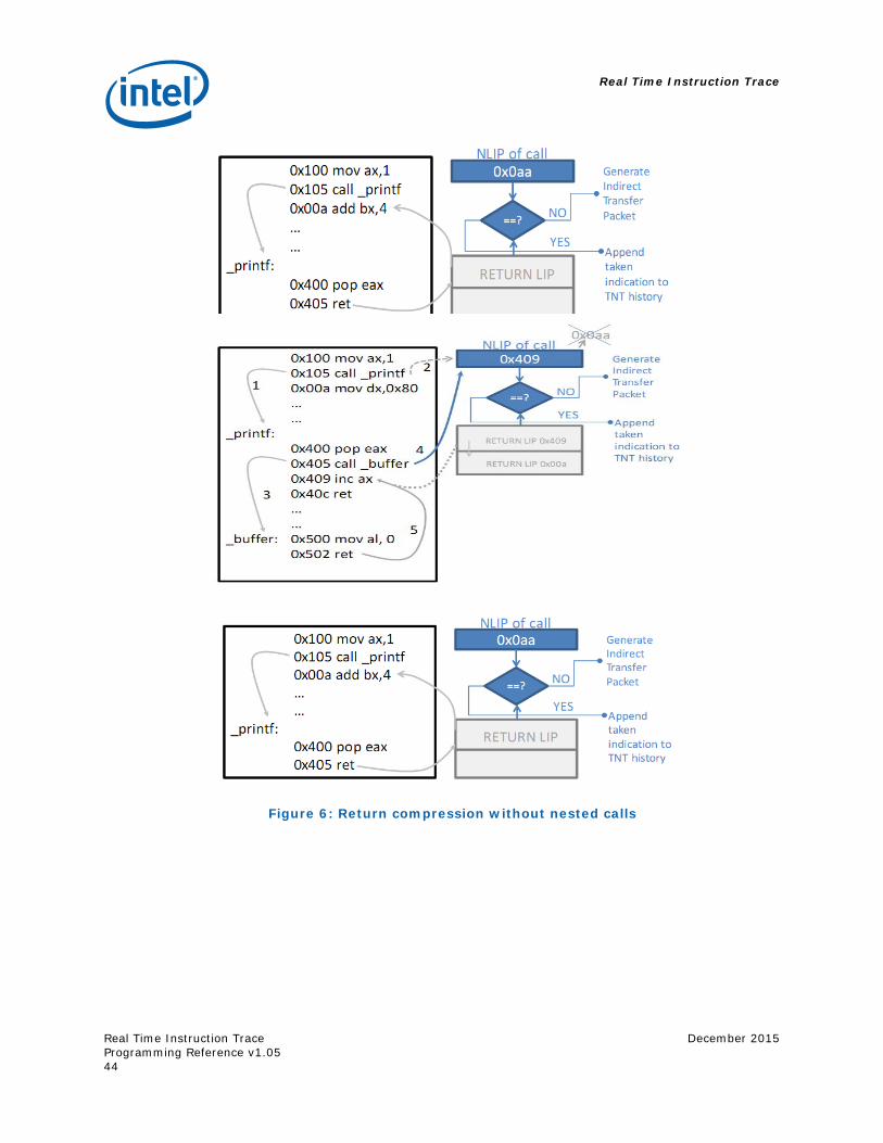
Real Time Instruction Trace
Real Time Instruction Trace Programming Reference v1.05
December 2015
44
Figure 6: Return compression without nested calls
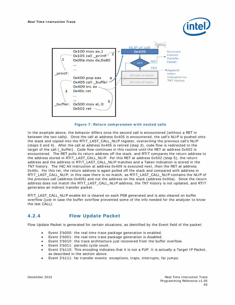
Real Time Instruction Trace
December 2015
Real Time Instruction Trace Programming Reference v1.05
45
Figure 7: Return compression with nested calls
In the example above, the behavior differs once the second call is encountered (without a RET in between the two calls). Once the call at address 0x405 is encountered, the call’s NLIP is pushed onto the stack and copied into the RTIT_LAST_CALL_NLIP register, overwriting the previous call’s NLIP (steps 3 and 4). After the call at address 0x405 is retired (step 3), code flow is redirected to the target of the call (_buffer). Code flow continues in this routine until the RET at address 0x502 is encountered. The RET pulls its return address off the stack, and RTIT compares the return address to the address stored in RTIT_LAST_CALL_NLIP. For this RET at address 0x502 (step 5), the return address and the address in RTIT_LAST_CALL_NLIP matches and a Taken indication is stored in the TNT history. The INC AX instruction at address 0x409 is executed next, then the RET at address 0x40c. For this ret, the return address is again pulled off the stack and compared with address in RTIT_LAST_CALL_NLIP; in this case there is no match, as RTIT_LAST_CALL_NLIP contains the NLIP of the previous call (address 0x405) and not the address on the stack (address 0x00a). Since the return address does not match the RTIT_LAST_CALL_NLIP address, the TNT history is not updated, and RTIT generates an indirect transfer packet.
RTIT_LAST_CALL_NLIP enable bit is cleared on each PSB generated and is also cleared on buffer overflow (just in case the buffer overflow prevented some of the info needed for the analyzer to know the last CALL).
4.2.4 Flow Update Packet
Flow Update Packet is generated for certain situations, as identified by the Event field of the packet:
Event 3’b000: the real time trace package generation is enabled. Event 3’b001: the real time trace package generation is disabled. Event 3’b010: the trace architecture just recovered from the buffer overflow. Event 3’b011: periodic cycle count. Event 3’b110: This encoding indicates that it is not a FUP. It is actually a Target IP Packet,
as described in the section above. Event 3’b111: far transfer events: exceptions, traps, interrupts, far jumps.
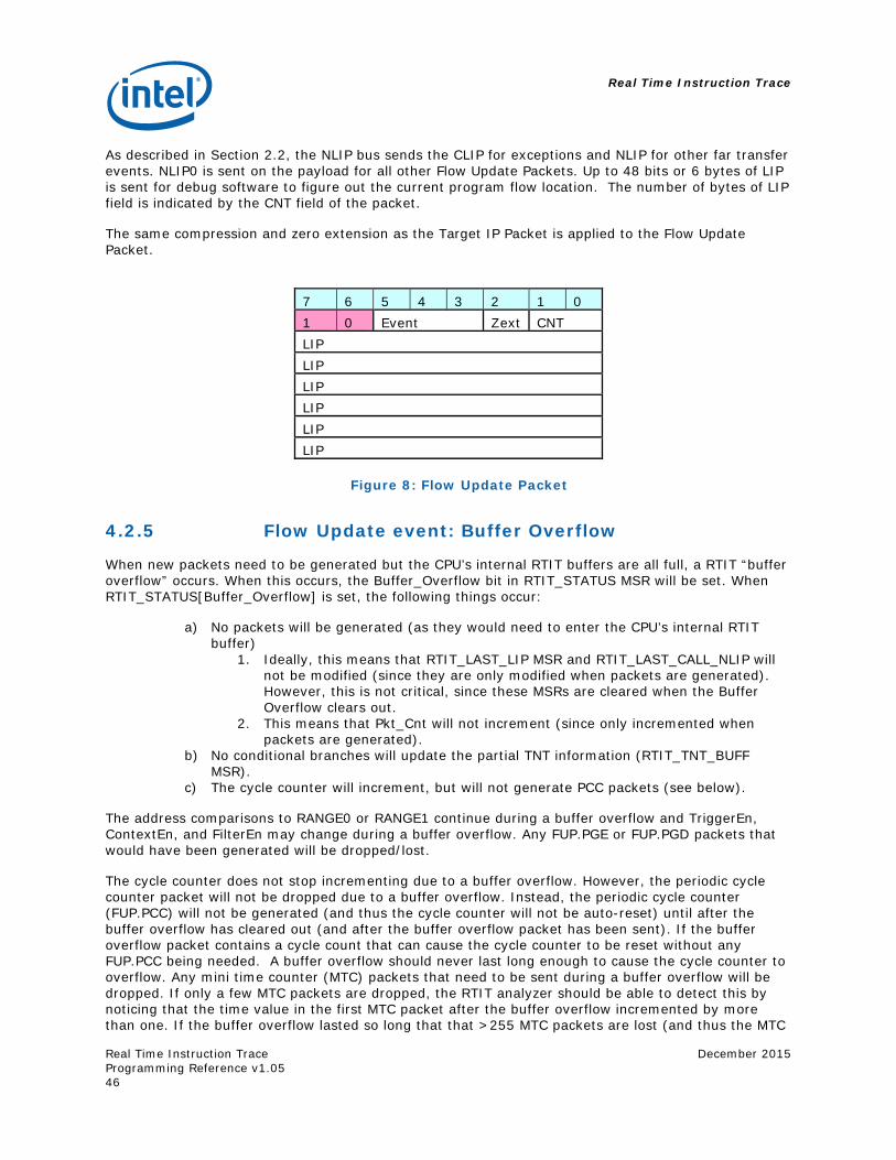
Real Time Instruction Trace
Real Time Instruction Trace Programming Reference v1.05
December 2015
46
As described in Section 2.2, the NLIP bus sends the CLIP for exceptions and NLIP for other far transfer events. NLIP0 is sent on the payload for all other Flow Update Packets. Up to 48 bits or 6 bytes of LIP is sent for debug software to figure out the current program flow location. The number of bytes of LIP field is indicated by the CNT field of the packet.
The same compression and zero extension as the Target IP Packet is applied to the Flow Update Packet.
7 6 5 4 3 2 1 0 1 0 Event Zext CNT LIP LIP LIP LIP LIP LIP
Figure 8: Flow Update Packet
4.2.5 Flow Update event: Buffer Overflow
When new packets need to be generated but the CPU’s internal RTIT buffers are all full, a RTIT “buffer overflow” occurs. When this occurs, the Buffer_Overflow bit in RTIT_STATUS MSR will be set. When RTIT_STATUS[Buffer_Overflow] is set, the following things occur:
a) No packets will be generated (as they would need to enter the CPU’s internal RTIT buffer)
1. Ideally, this means that RTIT_LAST_LIP MSR and RTIT_LAST_CALL_NLIP will not be modified (since they are only modified when packets are generated). However, this is not critical, since these MSRs are cleared when the Buffer Overflow clears out.
2. This means that Pkt_Cnt will not increment (since only incremented when packets are generated).
b) No conditional branches will update the partial TNT information (RTIT_TNT_BUFF MSR).
c) The cycle counter will increment, but will not generate PCC packets (see below).
The address comparisons to RANGE0 or RANGE1 continue during a buffer overflow and TriggerEn, ContextEn, and FilterEn may change during a buffer overflow. Any FUP.PGE or FUP.PGD packets that would have been generated will be dropped/lost.
The cycle counter does not stop incrementing due to a buffer overflow. However, the periodic cycle counter packet will not be dropped due to a buffer overflow. Instead, the periodic cycle counter (FUP.PCC) will not be generated (and thus the cycle counter will not be auto-reset) until after the buffer overflow has cleared out (and after the buffer overflow packet has been sent). If the buffer overflow packet contains a cycle count that can cause the cycle counter to be reset without any FUP.PCC being needed. A buffer overflow should never last long enough to cause the cycle counter to overflow. Any mini time counter (MTC) packets that need to be sent during a buffer overflow will be dropped. If only a few MTC packets are dropped, the RTIT analyzer should be able to detect this by noticing that the time value in the first MTC packet after the buffer overflow incremented by more than one. If the buffer overflow lasted so long that that >255 MTC packets are lost (and thus the MTC
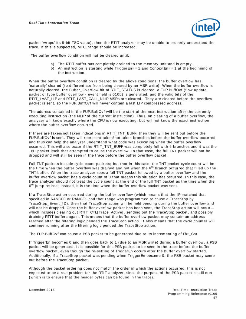
Real Time Instruction Trace
December 2015
Real Time Instruction Trace Programming Reference v1.05
47
packet ‘wraps’ its 8-bit TSC value), then the RTIT analyzer may be unable to properly understand the trace. If this is suspected, MTC_range should be increased.
The buffer overflow condition will not be cleared until:
a) The RTIT buffer has completely drained to the memory unit and is empty. b) An instruction is starting while TriggerEn==1 and ContextEn==1 at the beginning of
the instruction.
When the buffer overflow condition is cleared by the above conditions, the buffer overflow has ‘naturally’ cleared (to differentiate from being cleared by an MSR write). When the buffer overflow is naturally cleared, the Buffer_Overflow bit of RTIT_STATUS is cleared, a FUP.BuffOvf (flow update packet of type buffer overflow - event field is 010b) is generated, and the valid bits of the RTIT_LAST_LIP and RTIT_LAST_CALL_NLIP MSRs are cleared. They are cleared before the overflow packet is sent, so the FUP.BuffOvf will never contain a last LIP compressed address.
The address contained in the FUP.BuffOvf will be the start of the next instruction after the currently executing instruction (the NLIP of the current instruction). Thus, on clearing of a buffer overflow, the analyzer will know exactly where the CPU is now executing, but will not know the exact instruction where the buffer overflow occurred.
If there are taken/not taken indications in RTIT_TNT_BUFF, then they will be sent out before the FUP.BuffOvf is sent. They will represent taken/not taken branches before the buffer overflow occurred, and thus can help the analyzer understand what code was executing when the buffer overflow occurred. This will also occur if the RTIT_TNT_BUFF was completely full with 6 branches and it was the TNT packet itself that attempted to cause the overflow. In that case, the full TNT packet will not be dropped and will still be seen in the trace before the buffer overflow packet.
Full TNT packets include cycle count packets; but that in this case, the TNT packet cycle count will be the time when the buffer overflow was drained and not when the 6th branch occurred that filled up the TNT buffer. When the trace analyzer sees a full TNT packet followed by a buffer overflow and the buffer overflow packet has a cycle count of 0 that means this situation has occurred. In this case, the trace analyzer should not treat the cycle count at the end of the full TNT packet as the time when the 6th jump retired; instead, it is the time when the buffer overflow packet was sent. If a TraceStop action occurred during the buffer overflow (which means that the IP matched that specified in RANGE0 or RANGE1 and that range was programmed to cause a TraceStop by TraceStop_Event_ID), then that TraceStop action will be held pending during the buffer overflow and will not be dropped. Once the buffer overflow packet has been sent, the TraceStop action will occur—which includes clearing out RTIT_CTL[Trace_Active], sending out the TraceStop packet, and possibly draining RTIT buffers again. This means that the buffer overflow packet may contain an address reached after the filtering logic pended the TraceStop action. It also means that the cycle counter will continue running after the filtering logic pended the TraceStop action.
The FUP.BuffOvf can cause a PSB packet to be generated due to its incrementing of Pkt_Cnt.
If TriggerEn becomes 0 and then goes back to 1 (due to an MSR write) during a buffer overflow, a PSB packet will be generated. It is possible for this PSB packet to be seen in the trace before the buffer overflow packet, even though the re-setting of TriggerEn occurs after the buffer overflow started. Additionally, if a TraceStop packet was pending when TriggerEn became 0, the PSB packet may come out before the TraceStop packet.
Although the packet ordering does not match the order in which the actions occurred, this is not expected to be a real problem for the RTIT analyzer, since the purpose of the PSB packet is still met (which is to ensure that the header bytes can be found in the trace).
Real Time Instruction Trace
Real Time Instruction Trace Programming Reference v1.05
December 2015
48
The Buffer_Overflow can also be changed by software writing RTIT_STATUS MSR. Clearing the bit through an MSR write is not a ‘natural’ clearing and it will not cause a buffer overflow packet to be generated. If the Buffer_Overflow bit is set through an MSR write to RTIT_STATUS that must have the same effect as if a packet was generated when the buffer was full (e.g. preventing further packets from getting into the internal buffer while Buffer_Overflow bit is set).
If an RTIT drain occurs (e.g. as part of a WRMSR to RTIT_CTL) while Buffer_Overflow is set, the drain will complete without Buffer_Overflow being cleared. This is because Buffer_Overflow only clears naturally (meaning not through MSR write) at instruction boundaries. Thus it is possible for a drain to complete without forcing out the Buffer Overflow packet (FUP.BuffOvf) that is generated by the natural clearing of RTIT_STATUS[Buffer_Overflow].
4.2.6 Flow Update event: Packet Cycle Counter
This is commonly called “FUP.PCC”. The RTIT hardware will send out a Periodic Cycle Count (FUP.PCC) Packet at the beginning of an instruction when the MSB (bit 21) of RTIT_CNTP[CNTP] is set, the cycle count is enabled (RTIT_CTL[CYCLE_ACC]==1), and the processor is in the appropriate mode.
When LESS_PKTS is set, FUP.PCC packets are only sent out when (TriggerEn && ContextEn && FilterEn) == 1.
When LESS_PKTS is clear, FUP.PCC packets are only sent out when (TriggerEn && ContextEn) == 1.
The address in the FUP.PCC’s LIP field is the NLIP of the instruction (the first byte of the next sequential instruction). This is the same as the buffer overflow packet. This can lead to an address being sent out which is never executed (e.g. the instruction sequentially after a RET). The RTIT_CNTP packet may be delayed if another packet non-PSB needs to be sent out at the same time.
Although it is only sent out at instruction boundaries, it is normally sent out when it is ‘half full’ (its MSB is set). So there is little chance of the cycle counter overflowing before the FUP.PCC could be sent out.
Since the Periodic Cycle Count packet is only sent out in cycle accurate mode (assuming an MSR write isn’t used to set the MSB of CNTP), it will naturally include the cycle count. And thus sending it out will also clear out the cycle counter (CNTP) – since that happens whenever the cycle count packet is sent. Sometimes this packet is incorrectly referred to as the “Cycle Count Overflow packet”.
4.2.7 Flow Update event: Packet Generation Enable
This is commonly called “FUP.PGE”. This packet is generated when PacketEn transitions from 0 to 1.
This can happen for a range of reasons including: a) “Walking into the region” (having FilterEn become set due to the NLIP matching the region
specified by Filter EventID). b) Jumping into the region (having FilterEn become set due to the branch target being within the
region specified by Filter EventID). c) Having ContextEnable become 1 and already being in the right range.
a. This could happen due to a WRMSR to an RTIT MSR, a CR3 changing operation, a change in CPL, a VM-entry, or RSM.
d) Enabling RTIT (TriggerEn from 0 to 1) and being in the right mode and IP range such that ContextEn and FilterEn also become 1.
Real Time Instruction Trace
December 2015
Real Time Instruction Trace Programming Reference v1.05
49
The FUP.PGE is actually sent out by the instruction that ‘ends’ in the right mode/range.
The LIP carried in the FUP.PGE packet is the address of the next instruction that should execute (assuming no trap/interrupt), which will always be an address in the right mode/range.
4.2.8 Flow Update event: Packet Generation Disable
This is commonly called “FUP.PGD.” This packet is generated when PacketEn transitions from 1 to 0, with an exception mentioned later.
This can happen for a range of reasons including:
a) “Walking out the region” (having FilterEn become 0 due to the NLIP matching the end of the region specified by Filter EventID).
b) Jumping out the region (having FilterEn become cleared due to the branch target being outside the region specified by Filter EventID).
c) Having ContextEnable become 0. a. This could happen due to a WRMSR to an RTIT MSR, a CR3 changing operation, a
change in CPL, a VM-exit or a SMI.
The FUP.PGD is actually sent out by the instruction that ‘ends’ outside of the right mode/range. Thus, it is generated by an instruction that started with PacketEn set.
The LIP carried in the FUP.PGD packet is the NLIP of the instruction that caused PacketEn to go from 1 to 0. If it was not an instruction that caused PacketEn to be cleared (e.g., it was an interrupt or trap or VM exit), then it is the address that would be saved into the LBR FROM field, or into the VMCS or into the SMRAM.
There is one exception where PacketEn goes from 1 to 0 without a FUP.PGD being generated. A FUP.PGD may not be generated when TriggerEn becomes 0. This TriggerEn clearing could be due to an MSR write that clears TraceActive or Trace_En or by a TraceStop event that clears TraceActive. This aspect of the architecture may be changed in future versions of RTIT if it is a problem for software. This can cause PacketEn to become 0 without the contents of TNT_BUFF being forced out in a partial TNT. This could lead to a partial TNT on the next FUP.PGE (which is unusual; but allowed). That partial TNT would specify where RTIT was disabled.
4.2.9 Flow Update event: Far Transfer
This is commonly called “FUP.FAR”. It is sent out on far transfers to explain where the trace was before the far transfer. This is important for asynchronous transfers like faults and interrupts; but is sent out on all far transfers to be consistent. See table 2 (Classifying branches/COFI) for details of which instructions cause a FUP.FAR to be sent out. The address that is contained in the FUP.FAR is described in Table 1 (Address in various packets).
On a branch that would naturally generate both a FUP.FAR and a FUP.PGD, the FUP.PGD will replace the FUP.FAR and no FUP.FAR will be sent. This is a form of compression, and is also thought to simplify the hardware.
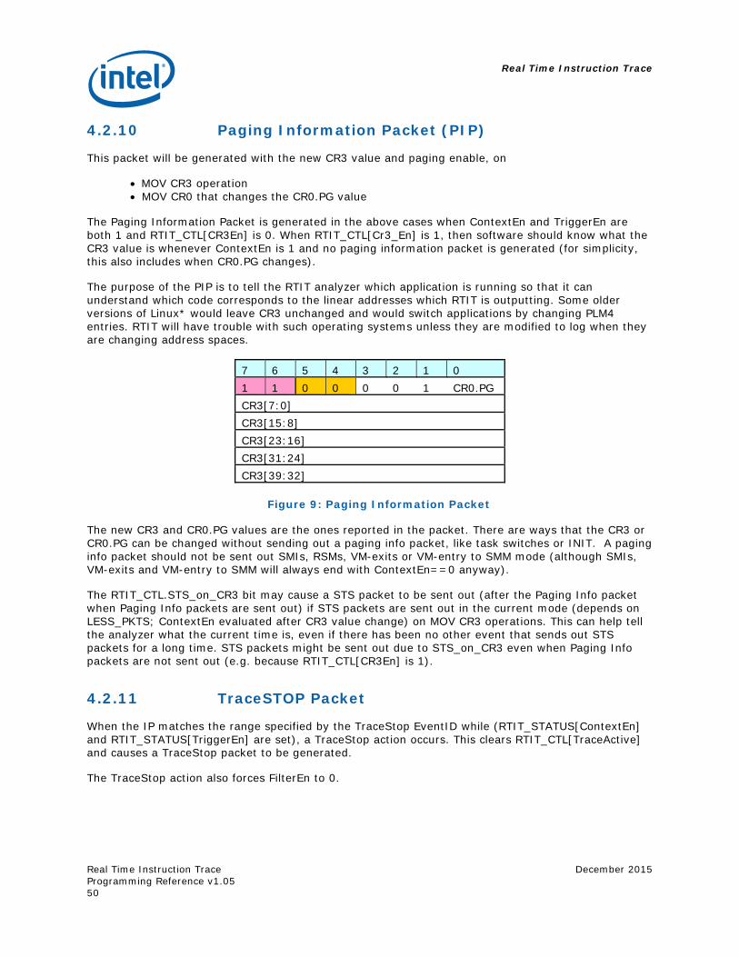
Real Time Instruction Trace
Real Time Instruction Trace Programming Reference v1.05
December 2015
50
4.2.10 Paging Information Packet (PIP)
This packet will be generated with the new CR3 value and paging enable, on
MOV CR3 operation MOV CR0 that changes the CR0.PG value
The Paging Information Packet is generated in the above cases when ContextEn and TriggerEn are both 1 and RTIT_CTL[CR3En] is 0. When RTIT_CTL[Cr3_En] is 1, then software should know what the CR3 value is whenever ContextEn is 1 and no paging information packet is generated (for simplicity, this also includes when CR0.PG changes).
The purpose of the PIP is to tell the RTIT analyzer which application is running so that it can understand which code corresponds to the linear addresses which RTIT is outputting. Some older versions of Linux* would leave CR3 unchanged and would switch applications by changing PLM4 entries. RTIT will have trouble with such operating systems unless they are modified to log when they are changing address spaces.
7 6 5 4 3 2 1 0 1 1 0 0 0 0 1 CR0.PG CR3[7:0] CR3[15:8] CR3[23:16] CR3[31:24] CR3[39:32]
Figure 9: Paging Information Packet
The new CR3 and CR0.PG values are the ones reported in the packet. There are ways that the CR3 or CR0.PG can be changed without sending out a paging info packet, like task switches or INIT. A paging info packet should not be sent out SMIs, RSMs, VM-exits or VM-entry to SMM mode (although SMIs, VM-exits and VM-entry to SMM will always end with ContextEn==0 anyway).
The RTIT_CTL.STS_on_CR3 bit may cause a STS packet to be sent out (after the Paging Info packet when Paging Info packets are sent out) if STS packets are sent out in the current mode (depends on LESS_PKTS; ContextEn evaluated after CR3 value change) on MOV CR3 operations. This can help tell the analyzer what the current time is, even if there has been no other event that sends out STS packets for a long time. STS packets might be sent out due to STS_on_CR3 even when Paging Info packets are not sent out (e.g. because RTIT_CTL[CR3En] is 1).
4.2.11 TraceSTOP Packet
When the IP matches the range specified by the TraceStop EventID while (RTIT_STATUS[ContextEn] and RTIT_STATUS[TriggerEn] are set), a TraceStop action occurs. This clears RTIT_CTL[TraceActive] and causes a TraceStop packet to be generated.
The TraceStop action also forces FilterEn to 0.
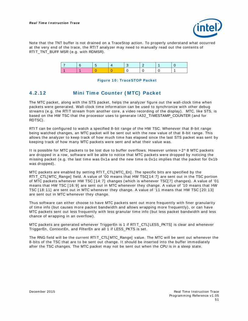
Real Time Instruction Trace
December 2015
Real Time Instruction Trace Programming Reference v1.05
51
Note that the TNT buffer is not drained on a TraceStop action. To properly understand what occurred at the very end of the trace, the RTIT analyzer may need to manually read out the contents of RTIT_TNT_BUFF MSR (e.g. with RDMSR).
7 6 5 4 3 2 1 0 1 1 0 0 0 0 0 1
Figure 10: TraceSTOP Packet
4.2.12 Mini Time Counter (MTC) Packet
The MTC packet, along with the STS packet, helps the analyzer figure out the wall-clock time when packets were generated. Wall-clock time information can be used to synchronize with other debug streams (e.g. the RTIT stream from another core, a video recording of the display). MTC, like STS, is based on the HW TSC that the processor uses to generate IA32_TIMESTAMP_COUNTER (and for RDTSC).
RTIT can be configured to watch a specified 8-bit range of the HW TSC. Whenever that 8-bit range being watched changes, an MTC packet will be sent out with the new value of that 8-bit range. This allows the analyzer to keep track of how much time has elapsed since the last STS packet was sent by keeping track of how many MTC packets were sent and what their value was.
It is possible for MTC packets to be lost due to buffer overflows. However unless >2^8 MTC packets are dropped in a row, software will be able to notice that MTC packets were dropped by noticing the missing packet (e.g. the last time was 0x1a and the new time is 0x1c implies that the packet for 0x1b was dropped).
MTC packets are enabled by setting RTIT_CTL[MTC_En]. The specific bits are specified by the RTIT_CTL[MTC_Range] field. A value of ’00 means that HW TSC[14:7] are sent out in the TSC portion of MTC packets whenever HW TSC [14:7] changes (which is whenever TSC[7] changes). A value of ’01 means that HW TSC [16:9] are sent out in MTC whenever they change. A value of ’10 means that HW TSC [18:11] are sent out in MTC whenever they change. A value of ’11 means that HW TSC [20:13] are sent out in MTC whenever they change.
Thus software can either choose to have MTC packets sent out more frequently with finer granularity of time info (but causes more packet bandwidth and allows wrapping more frequently), or can have MTC packets sent out less frequently with less granular time info (but less packet bandwidth and less chance of wrapping in an overflow).
MTC packets are generated whenever TriggerEn is 1 if RTIT_CTL[LESS_PKTS] is clear and whenever TriggerEn, ContextEn, and FilterEn are all 1 if LESS_PKTS is set.
The RNG field will be the current RTIT_CTL[MTC_Range] value. The MTC will be sent out whenever the 8-bits of the TSC that are to be sent out change. It should be inserted into the buffer immediately after the TSC changes. The MTC packet may not be sent out when the CPU is in a sleep state.
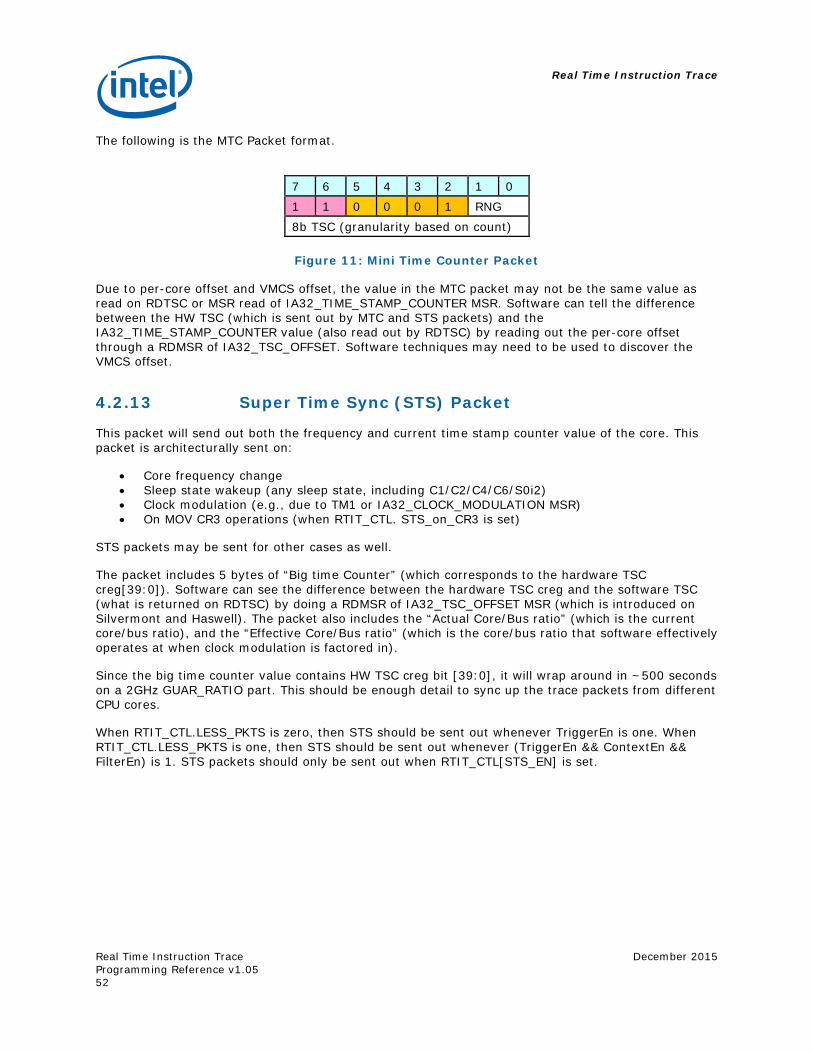
Real Time Instruction Trace
Real Time Instruction Trace Programming Reference v1.05
December 2015
52
The following is the MTC Packet format.
7 6 5 4 3 2 1 0 1 1 0 0 0 1 RNG 8b TSC (granularity based on count)
Figure 11: Mini Time Counter Packet
Due to per-core offset and VMCS offset, the value in the MTC packet may not be the same value as read on RDTSC or MSR read of IA32_TIME_STAMP_COUNTER MSR. Software can tell the difference between the HW TSC (which is sent out by MTC and STS packets) and the IA32_TIME_STAMP_COUNTER value (also read out by RDTSC) by reading out the per-core offset through a RDMSR of IA32_TSC_OFFSET. Software techniques may need to be used to discover the VMCS offset.
4.2.13 Super Time Sync (STS) Packet
This packet will send out both the frequency and current time stamp counter value of the core. This packet is architecturally sent on:
Core frequency change Sleep state wakeup (any sleep state, including C1/C2/C4/C6/S0i2) Clock modulation (e.g., due to TM1 or IA32_CLOCK_MODULATION MSR) On MOV CR3 operations (when RTIT_CTL. STS_on_CR3 is set)
STS packets may be sent for other cases as well.
The packet includes 5 bytes of “Big time Counter” (which corresponds to the hardware TSC creg[39:0]). Software can see the difference between the hardware TSC creg and the software TSC (what is returned on RDTSC) by doing a RDMSR of IA32_TSC_OFFSET MSR (which is introduced on Silvermont and Haswell). The packet also includes the “Actual Core/Bus ratio” (which is the current core/bus ratio), and the “Effective Core/Bus ratio” (which is the core/bus ratio that software effectively operates at when clock modulation is factored in).
Since the big time counter value contains HW TSC creg bit [39:0], it will wrap around in ~500 seconds on a 2GHz GUAR_RATIO part. This should be enough detail to sync up the trace packets from different CPU cores.
When RTIT_CTL.LESS_PKTS is zero, then STS should be sent out whenever TriggerEn is one. When RTIT_CTL.LESS_PKTS is one, then STS should be sent out whenever (TriggerEn && ContextEn && FilterEn) is 1. STS packets should only be sent out when RTIT_CTL[STS_EN] is set.
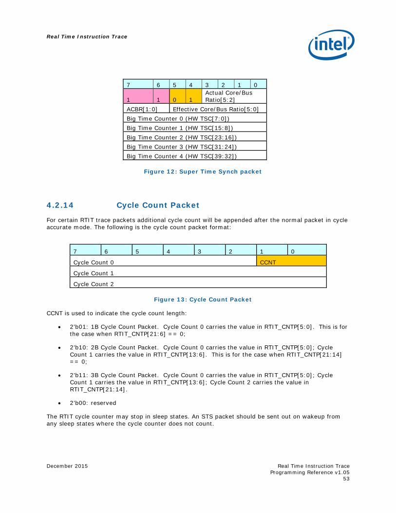
Real Time Instruction Trace
December 2015
Real Time Instruction Trace Programming Reference v1.05
53
7 6 5 4 3 2 1 0
1 1 0 1 Actual Core/Bus Ratio[5:2]
ACBR[1:0] Effective Core/Bus Ratio[5:0] Big Time Counter 0 (HW TSC[7:0]) Big Time Counter 1 (HW TSC[15:8]) Big Time Counter 2 (HW TSC[23:16]) Big Time Counter 3 (HW TSC[31:24]) Big Time Counter 4 (HW TSC[39:32])
Figure 12: Super Time Synch packet
4.2.14 Cycle Count Packet
For certain RTIT trace packets additional cycle count will be appended after the normal packet in cycle accurate mode. The following is the cycle count packet format:
7 6 5 4 3 2 1 0
Cycle Count 0 CCNT
Cycle Count 1
Cycle Count 2
Figure 13: Cycle Count Packet
CCNT is used to indicate the cycle count length:
2’b01: 1B Cycle Count Packet. Cycle Count 0 carries the value in RTIT_CNTP[5:0]. This is for the case when RTIT_CNTP[21:6] == 0;
2’b10: 2B Cycle Count Packet. Cycle Count 0 carries the value in RTIT_CNTP[5:0]; Cycle Count 1 carries the value in RTIT_CNTP[13:6]. This is for the case when RTIT_CNTP[21:14] == 0;
2’b11: 3B Cycle Count Packet. Cycle Count 0 carries the value in RTIT_CNTP[5:0]; Cycle Count 1 carries the value in RTIT_CNTP[13:6]; Cycle Count 2 carries the value in RTIT_CNTP[21:14].
2’b00: reserved
The RTIT cycle counter may stop in sleep states. An STS packet should be sent out on wakeup from any sleep states where the cycle counter does not count.
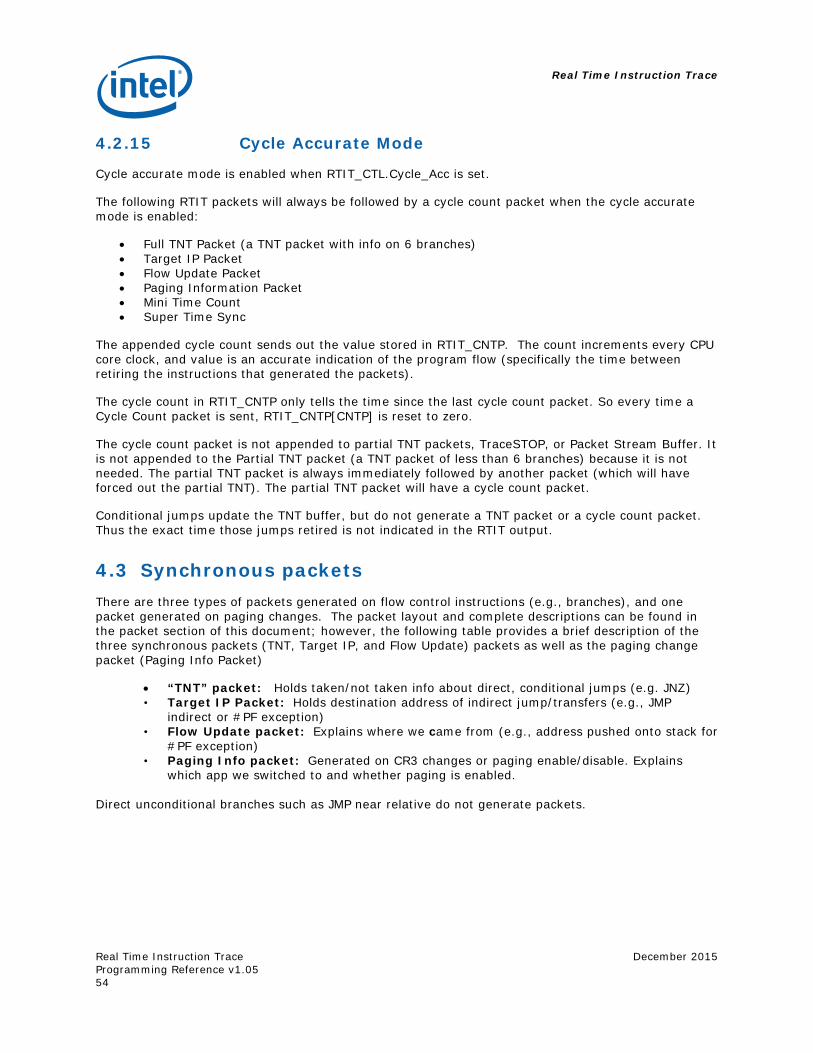
Real Time Instruction Trace
Real Time Instruction Trace Programming Reference v1.05
December 2015
54
4.2.15 Cycle Accurate Mode
Cycle accurate mode is enabled when RTIT_CTL.Cycle_Acc is set.
The following RTIT packets will always be followed by a cycle count packet when the cycle accurate mode is enabled:
Full TNT Packet (a TNT packet with info on 6 branches) Target IP Packet Flow Update Packet Paging Information Packet Mini Time Count Super Time Sync
The appended cycle count sends out the value stored in RTIT_CNTP. The count increments every CPU core clock, and value is an accurate indication of the program flow (specifically the time between retiring the instructions that generated the packets).
The cycle count in RTIT_CNTP only tells the time since the last cycle count packet. So every time a Cycle Count packet is sent, RTIT_CNTP[CNTP] is reset to zero.
The cycle count packet is not appended to partial TNT packets, TraceSTOP, or Packet Stream Buffer. It is not appended to the Partial TNT packet (a TNT packet of less than 6 branches) because it is not needed. The partial TNT packet is always immediately followed by another packet (which will have forced out the partial TNT). The partial TNT packet will have a cycle count packet.
Conditional jumps update the TNT buffer, but do not generate a TNT packet or a cycle count packet. Thus the exact time those jumps retired is not indicated in the RTIT output.
4.3 Synchronous packets There are three types of packets generated on flow control instructions (e.g., branches), and one packet generated on paging changes. The packet layout and complete descriptions can be found in the packet section of this document; however, the following table provides a brief description of the three synchronous packets (TNT, Target IP, and Flow Update) packets as well as the paging change packet (Paging Info Packet)
“TNT” packet: Holds taken/not taken info about direct, conditional jumps (e.g. JNZ) • Target IP Packet: Holds destination address of indirect jump/transfers (e.g., JMP
indirect or #PF exception) • Flow Update packet: Explains where we came from (e.g., address pushed onto stack for
#PF exception) • Paging Info packet: Generated on CR3 changes or paging enable/disable. Explains
which app we switched to and whether paging is enabled.
Direct unconditional branches such as JMP near relative do not generate packets.
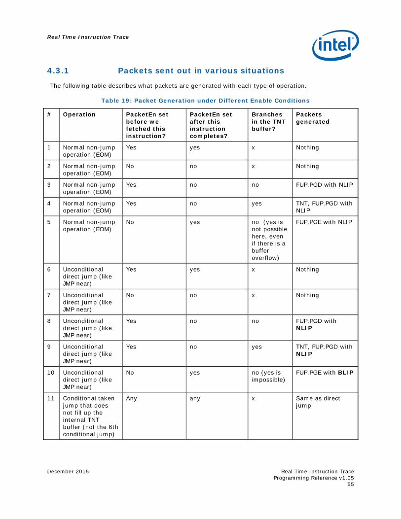
Real Time Instruction Trace
December 2015
Real Time Instruction Trace Programming Reference v1.05
55
4.3.1 Packets sent out in various situations
The following table describes what packets are generated with each type of operation.
Table 19: Packet Generation under Different Enable Conditions
# Operation PacketEn set before we fetched this instruction?
PacketEn set after this instruction completes?
Branches in the TNT buffer?
Packets generated
1 Normal non-jump operation (EOM)
Yes yes x Nothing
2 Normal non-jump operation (EOM)
No no x Nothing
3 Normal non-jump operation (EOM)
Yes no no FUP.PGD with NLIP
4 Normal non-jump operation (EOM)
Yes no yes TNT, FUP.PGD with NLIP
5 Normal non-jump operation (EOM)
No yes no (yes is not possible here, even if there is a buffer overflow)
FUP.PGE with NLIP
6 Unconditional direct jump (like JMP near)
Yes yes x Nothing
7 Unconditional direct jump (like JMP near)
No no x Nothing
8 Unconditional direct jump (like JMP near)
Yes no no FUP.PGD with NLIP
9 Unconditional direct jump (like JMP near)
Yes no yes TNT, FUP.PGD with NLIP
10 Unconditional direct jump (like JMP near)
No yes no (yes is impossible)
FUP.PGE with BLIP
11 Conditional taken jump that does not fill up the internal TNT buffer (not the 6th conditional jump)
Any any x Same as direct jump
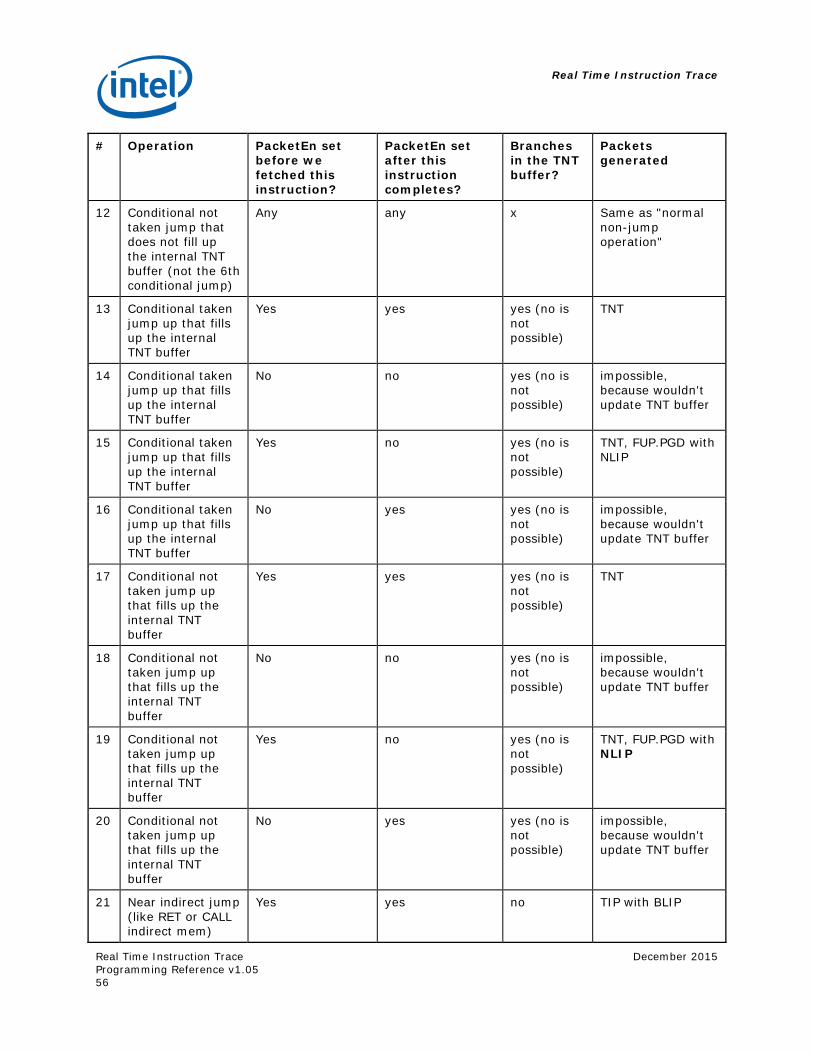
Real Time Instruction Trace
Real Time Instruction Trace Programming Reference v1.05
December 2015
56
# Operation PacketEn set before we fetched this instruction?
PacketEn set after this instruction completes?
Branches in the TNT buffer?
Packets generated
12 Conditional not taken jump that does not fill up the internal TNT buffer (not the 6th conditional jump)
Any any x Same as "normal non-jump operation"
13 Conditional taken jump up that fills up the internal TNT buffer
Yes yes yes (no is not possible)
TNT
14 Conditional taken jump up that fills up the internal TNT buffer
No no yes (no is not possible)
impossible, because wouldn't update TNT buffer
15 Conditional taken jump up that fills up the internal TNT buffer
Yes no yes (no is not possible)
TNT, FUP.PGD with NLIP
16 Conditional taken jump up that fills up the internal TNT buffer
No yes yes (no is not possible)
impossible, because wouldn't update TNT buffer
17 Conditional not taken jump up that fills up the internal TNT buffer
Yes yes yes (no is not possible)
TNT
18 Conditional not taken jump up that fills up the internal TNT buffer
No no yes (no is not possible)
impossible, because wouldn't update TNT buffer
19 Conditional not taken jump up that fills up the internal TNT buffer
Yes no yes (no is not possible)
TNT, FUP.PGD with NLIP
20 Conditional not taken jump up that fills up the internal TNT buffer
No yes yes (no is not possible)
impossible, because wouldn't update TNT buffer
21 Near indirect jump (like RET or CALL indirect mem)
Yes yes no TIP with BLIP
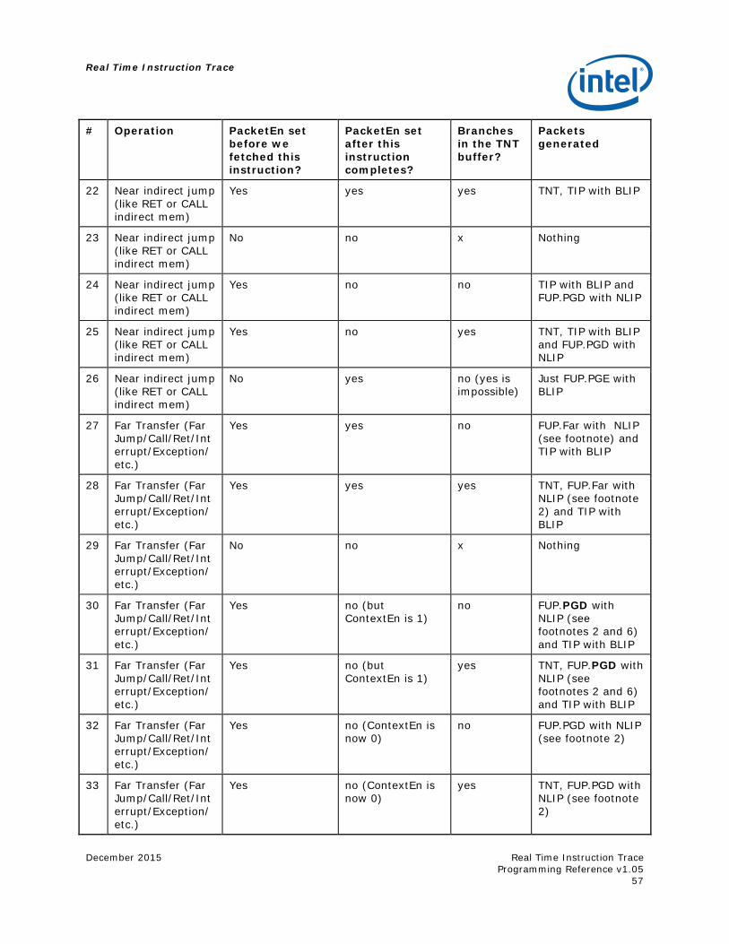
Real Time Instruction Trace
December 2015
Real Time Instruction Trace Programming Reference v1.05
57
# Operation PacketEn set before we fetched this instruction?
PacketEn set after this instruction completes?
Branches in the TNT buffer?
Packets generated
22 Near indirect jump (like RET or CALL indirect mem)
Yes yes yes TNT, TIP with BLIP
23 Near indirect jump (like RET or CALL indirect mem)
No no x Nothing
24 Near indirect jump (like RET or CALL indirect mem)
Yes no no TIP with BLIP and FUP.PGD with NLIP
25 Near indirect jump (like RET or CALL indirect mem)
Yes no yes TNT, TIP with BLIP and FUP.PGD with NLIP
26 Near indirect jump (like RET or CALL indirect mem)
No yes no (yes is impossible)
Just FUP.PGE with BLIP
27 Far Transfer (Far Jump/Call/Ret/Interrupt/Exception/etc.)
Yes yes no FUP.Far with NLIP (see footnote) and TIP with BLIP
28 Far Transfer (Far Jump/Call/Ret/Interrupt/Exception/etc.)
Yes yes yes TNT, FUP.Far with NLIP (see footnote 2) and TIP with BLIP
29 Far Transfer (Far Jump/Call/Ret/Interrupt/Exception/etc.)
No no x Nothing
30 Far Transfer (Far Jump/Call/Ret/Interrupt/Exception/etc.)
Yes no (but ContextEn is 1)
no FUP.PGD with NLIP (see footnotes 2 and 6) and TIP with BLIP
31 Far Transfer (Far Jump/Call/Ret/Interrupt/Exception/etc.)
Yes no (but ContextEn is 1)
yes TNT, FUP.PGD with NLIP (see footnotes 2 and 6) and TIP with BLIP
32 Far Transfer (Far Jump/Call/Ret/Interrupt/Exception/etc.)
Yes no (ContextEn is now 0)
no FUP.PGD with NLIP (see footnote 2)
33 Far Transfer (Far Jump/Call/Ret/Interrupt/Exception/etc.)
Yes no (ContextEn is now 0)
yes TNT, FUP.PGD with NLIP (see footnote 2)
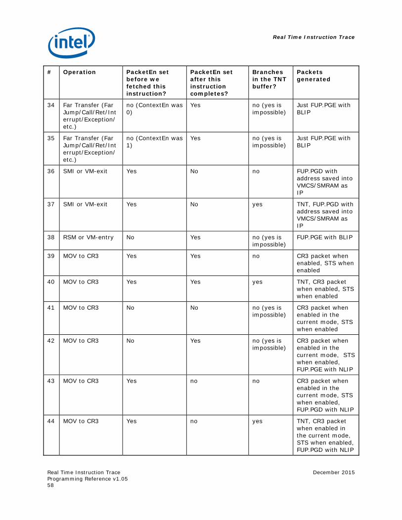
Real Time Instruction Trace
Real Time Instruction Trace Programming Reference v1.05
December 2015
58
# Operation PacketEn set before we fetched this instruction?
PacketEn set after this instruction completes?
Branches in the TNT buffer?
Packets generated
34 Far Transfer (Far Jump/Call/Ret/Interrupt/Exception/etc.)
no (ContextEn was 0)
Yes no (yes is impossible)
Just FUP.PGE with BLIP
35 Far Transfer (Far Jump/Call/Ret/Interrupt/Exception/etc.)
no (ContextEn was 1)
Yes no (yes is impossible)
Just FUP.PGE with BLIP
36 SMI or VM-exit Yes No no FUP.PGD with address saved into VMCS/SMRAM as IP
37 SMI or VM-exit Yes No yes TNT, FUP.PGD with address saved into VMCS/SMRAM as IP
38 RSM or VM-entry No Yes no (yes is impossible)
FUP.PGE with BLIP
39 MOV to CR3 Yes Yes no CR3 packet when enabled, STS when enabled
40 MOV to CR3 Yes Yes yes TNT, CR3 packet when enabled, STS when enabled
41 MOV to CR3 No No no (yes is impossible)
CR3 packet when enabled in the current mode, STS when enabled
42 MOV to CR3 No Yes no (yes is impossible)
CR3 packet when enabled in the current mode, STS when enabled, FUP.PGE with NLIP
43 MOV to CR3 Yes no no CR3 packet when enabled in the current mode, STS when enabled, FUP.PGD with NLIP
44 MOV to CR3 Yes no yes TNT, CR3 packet when enabled in the current mode, STS when enabled, FUP.PGD with NLIP
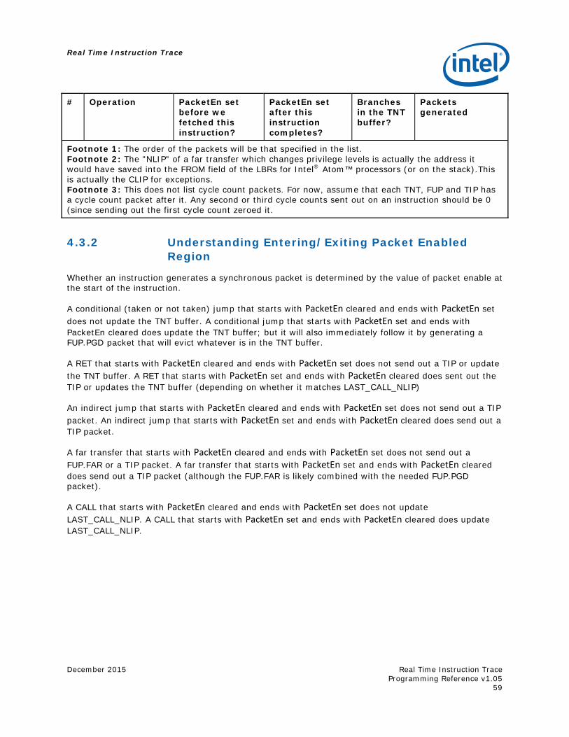
Real Time Instruction Trace
December 2015
Real Time Instruction Trace Programming Reference v1.05
59
# Operation PacketEn set before we fetched this instruction?
PacketEn set after this instruction completes?
Branches in the TNT buffer?
Packets generated
Footnote 1: The order of the packets will be that specified in the list. Footnote 2: The "NLIP" of a far transfer which changes privilege levels is actually the address it would have saved into the FROM field of the LBRs for Intel® Atom™ processors (or on the stack).This is actually the CLIP for exceptions. Footnote 3: This does not list cycle count packets. For now, assume that each TNT, FUP and TIP has a cycle count packet after it. Any second or third cycle counts sent out on an instruction should be 0 (since sending out the first cycle count zeroed it.
4.3.2 Understanding Entering/Exiting Packet Enabled Region
Whether an instruction generates a synchronous packet is determined by the value of packet enable at the start of the instruction.
A conditional (taken or not taken) jump that starts with PacketEn cleared and ends with PacketEn set does not update the TNT buffer. A conditional jump that starts with PacketEn set and ends with PacketEn cleared does update the TNT buffer; but it will also immediately follow it by generating a FUP.PGD packet that will evict whatever is in the TNT buffer.
A RET that starts with PacketEn cleared and ends with PacketEn set does not send out a TIP or update the TNT buffer. A RET that starts with PacketEn set and ends with PacketEn cleared does sent out the TIP or updates the TNT buffer (depending on whether it matches LAST_CALL_NLIP)
An indirect jump that starts with PacketEn cleared and ends with PacketEn set does not send out a TIP packet. An indirect jump that starts with PacketEn set and ends with PacketEn cleared does send out a TIP packet.
A far transfer that starts with PacketEn cleared and ends with PacketEn set does not send out a FUP.FAR or a TIP packet. A far transfer that starts with PacketEn set and ends with PacketEn cleared does send out a TIP packet (although the FUP.FAR is likely combined with the needed FUP.PGD packet).
A CALL that starts with PacketEn cleared and ends with PacketEn set does not update LAST_CALL_NLIP. A CALL that starts with PacketEn set and ends with PacketEn cleared does update LAST_CALL_NLIP.
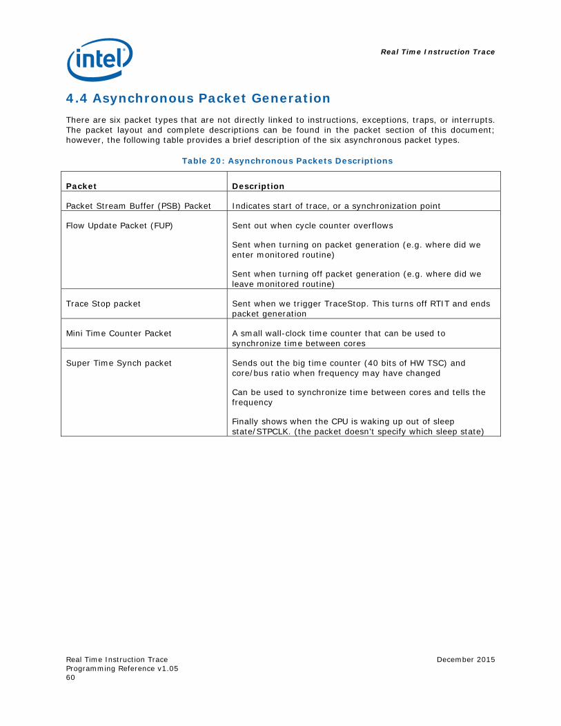
Real Time Instruction Trace
Real Time Instruction Trace Programming Reference v1.05
December 2015
60
4.4 Asynchronous Packet Generation There are six packet types that are not directly linked to instructions, exceptions, traps, or interrupts. The packet layout and complete descriptions can be found in the packet section of this document; however, the following table provides a brief description of the six asynchronous packet types.
Table 20: Asynchronous Packets Descriptions
Packet Description
Packet Stream Buffer (PSB) Packet Indicates start of trace, or a synchronization point
Flow Update Packet (FUP) Sent out when cycle counter overflows
Sent when turning on packet generation (e.g. where did we enter monitored routine)
Sent when turning off packet generation (e.g. where did we leave monitored routine)
Trace Stop packet Sent when we trigger TraceStop. This turns off RTIT and ends packet generation
Mini Time Counter Packet A small wall-clock time counter that can be used to synchronize time between cores
Super Time Synch packet Sends out the big time counter (40 bits of HW TSC) and core/bus ratio when frequency may have changed
Can be used to synchronize time between cores and tells the frequency
Finally shows when the CPU is waking up out of sleep state/STPCLK. (the packet doesn’t specify which sleep state)
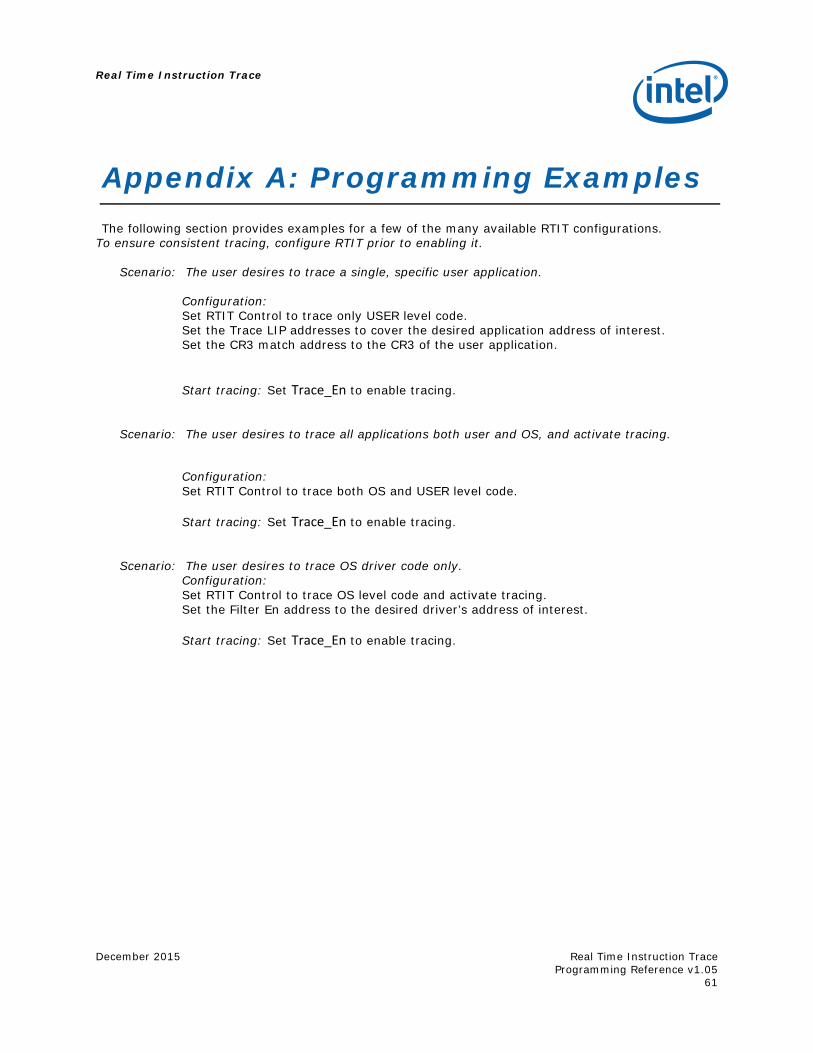
Real Time Instruction Trace
December 2015
Real Time Instruction Trace Programming Reference v1.05
61
Appendix A: Programming Examples The following section provides examples for a few of the many available RTIT configurations.
To ensure consistent tracing, configure RTIT prior to enabling it. Scenario: The user desires to trace a single, specific user application.
Configuration: Set RTIT Control to trace only USER level code. Set the Trace LIP addresses to cover the desired application address of interest. Set the CR3 match address to the CR3 of the user application. Start tracing: Set Trace_En to enable tracing.
Scenario: The user desires to trace all applications both user and OS, and activate tracing.
Configuration: Set RTIT Control to trace both OS and USER level code. Start tracing: Set Trace_En to enable tracing.
Scenario: The user desires to trace OS driver code only.
Configuration: Set RTIT Control to trace OS level code and activate tracing. Set the Filter En address to the desired driver’s address of interest.
Start tracing: Set Trace_En to enable tracing.
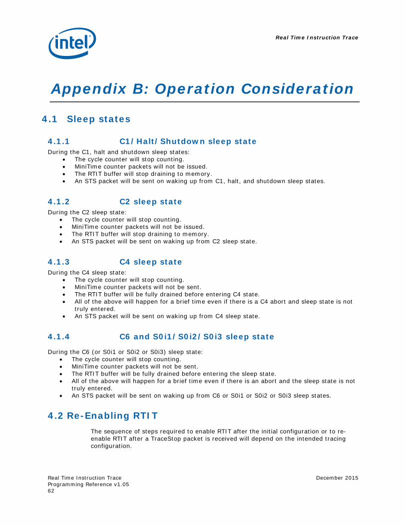
Real Time Instruction Trace
Real Time Instruction Trace Programming Reference v1.05
December 2015
62
Appendix B: Operation Consideration
4.1 Sleep states
4.1.1 C1/Halt/Shutdown sleep state During the C1, halt and shutdown sleep states:
The cycle counter will stop counting. MiniTime counter packets will not be issued. The RTIT buffer will stop draining to memory. An STS packet will be sent on waking up from C1, halt, and shutdown sleep states.
4.1.2 C2 sleep state During the C2 sleep state:
The cycle counter will stop counting. MiniTime counter packets will not be issued. The RTIT buffer will stop draining to memory. An STS packet will be sent on waking up from C2 sleep state.
4.1.3 C4 sleep state During the C4 sleep state:
The cycle counter will stop counting. MiniTime counter packets will not be sent. The RTIT buffer will be fully drained before entering C4 state. All of the above will happen for a brief time even if there is a C4 abort and sleep state is not
truly entered. An STS packet will be sent on waking up from C4 sleep state.
4.1.4 C6 and S0i1/S0i2/S0i3 sleep state
During the C6 (or S0i1 or S0i2 or S0i3) sleep state: The cycle counter will stop counting. MiniTime counter packets will not be sent. The RTIT buffer will be fully drained before entering the sleep state. All of the above will happen for a brief time even if there is an abort and the sleep state is not
truly entered. An STS packet will be sent on waking up from C6 or S0i1 or S0i2 or S0i3 sleep states.
4.2 Re-Enabling RTIT The sequence of steps required to enable RTIT after the initial configuration or to re-enable RTIT after a TraceStop packet is received will depend on the intended tracing configuration.
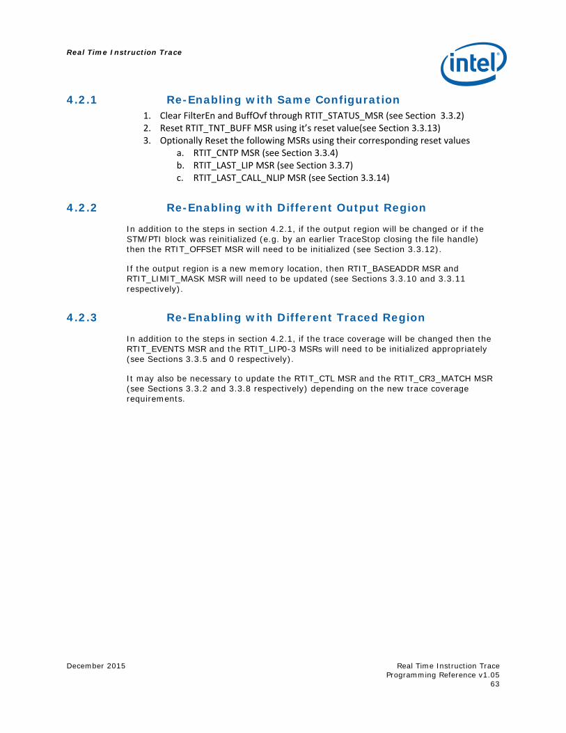
Real Time Instruction Trace
December 2015
Real Time Instruction Trace Programming Reference v1.05
63
4.2.1 Re-Enabling with Same Configuration 1. Clear FilterEn and BuffOvf through RTIT_STATUS_MSR (see Section 3.3.2) 2. Reset RTIT_TNT_BUFF MSR using it’s reset value(see Section 3.3.13) 3. Optionally Reset the following MSRs using their corresponding reset values
a. RTIT_CNTP MSR (see Section 3.3.4) b. RTIT_LAST_LIP MSR (see Section 3.3.7) c. RTIT_LAST_CALL_NLIP MSR (see Section 3.3.14)
4.2.2 Re-Enabling with Different Output Region
In addition to the steps in section 4.2.1, if the output region will be changed or if the STM/PTI block was reinitialized (e.g. by an earlier TraceStop closing the file handle) then the RTIT_OFFSET MSR will need to be initialized (see Section 3.3.12).
If the output region is a new memory location, then RTIT_BASEADDR MSR and RTIT_LIMIT_MASK MSR will need to be updated (see Sections 3.3.10 and 3.3.11 respectively).
4.2.3 Re-Enabling with Different Traced Region
In addition to the steps in section 4.2.1, if the trace coverage will be changed then the RTIT_EVENTS MSR and the RTIT_LIP0-3 MSRs will need to be initialized appropriately (see Sections 3.3.5 and 0 respectively).
It may also be necessary to update the RTIT_CTL MSR and the RTIT_CR3_MATCH MSR (see Sections 3.3.2 and 3.3.8 respectively) depending on the new trace coverage requirements.
Real Time Instruction Trace
Real Time Instruction Trace Programming Reference v1.05
December 2015
64
Appendix C: Background and Related Processor Mechanisms
4.3 Existing debug and performance monitoring The following are a list of available debug and monitoring features in Intel® Atom™ processors.
Break point LBR/LER Performance monitoring/PEBS DS for BTS/PEBS
Those features are compared with real time trace in the following sections.
4.4 Break point There are 4 sets of debug break point registers, which are stored in 64b MSR DR0 through DR3. Depending on configuration bits R/W0 though R/W1 in MSR DR7, the following are the possible actions:
00 — Break on instruction execution only. 01 — Break on data writes only. 10 — Break on I/O reads or writes. 11 — Break on data reads or writes but not instruction fetches.
After the break point trigger, a fault is raised for instruction break point, and a trap is raised for data and I/O access.
4.5 LBR/LER After branch instruction retired, or after exception, the FROM and TO information of the LIP is collected in a buffer. This buffer can be drained out of system bus or into the memory with processor support.
Real time trace leverages extensively the LBR/LER buffer with regard to the indirect jump. The target destination LIP will be carried out in branch address packet. But real time trace does not just output the raw LIP, as stored in LBR. The MSBs that do not change from previous LIP packet will be suppressed, and MSBs of zero will also be suppressed.
For direct jump where TO Lip is readily available from the assembly code, a simple TAKEN or NOT TAKEN bit is sent by real time trace to indicate the program flow, and up to 6 T/NT bits can be packed in a single byte of trace packet.
Except for the branch prediction, real time trace covers all the information in LBR/LER, with efficiency greatly improved by compression.
The draining of the buffer is discussed in BTS/DS section.
Real Time Instruction Trace
December 2015
Real Time Instruction Trace Programming Reference v1.05
65
4.6 Performance monitoring/PEBS There are architecturally defined performance counters to monitor events such as:
Unhalted Core Cycles Instruction Retired Unhalted Reference Cycles LLC Reference LLC Misses Branch Instruction Retired Branch Misses Retired
And PEBS counts more precise events such as how many load retired that missed L1.
Real time trace is different in the following:
Real time trace counts events at instruction level. i.e., how many times the instruction in certain LIP is executed. This event can be used as enabling events for counter. As counters in real time trace are fully programmable, it is easily concatenated for larger capacity.
Real time trace provide cycle accurate mode, so that the exact flow and timing of the program is available.
4.7 DS for BTS/PEBS DS is the way to write LBR and performance counters into memory. IA32_DS_AREA MSR holds the LIP to DS buffer management area.
DS save area is within kernel space, and can be larger than a page and can straddle page boundaries.
DS buffer management area contains buffer base to BTS/PEBS, along with index, max IP, threshold and other information
Based on the buffer base and index, BTS/PEBS can be written into appropriate part of the memory.
The BTS/PEBS write can be configured so that if the threshold is cross, an exception is raised.
Based on the way how DS storage is managed, the processor first has to fetch the buffer management information from DS save area and then store the buffer. This is a cycle-consuming process.
4.8 CR3 States CR3 is the control register by which the memory paging is managed. This register can be loaded with MOV instruction.
X86 supports 3 paging modes:
32-bit PAE IA-32e
For 32-bit mode, the following fields of CR3 are used:
Bit 3: PWT
Real Time Instruction Trace
Real Time Instruction Trace Programming Reference v1.05
December 2015
66
Bit 4: PCD Bit [31:12]: Page directory address
For PAE mode, the following fields of CR3 are used:
Bit [31:5]: Address of page-directory-pointer table For IA-32E mode, the following fields of CR3 are used:
Bit 3: PWT Bit 4: PCD Bit [`MAXPHYADDR-1:12]: physical address to PML4 table
4.9 Virtual Machine Extension VMX refers to Virtual Machine EXtension, which supports processor virtualization for multiple software environments.
The following instructions to enter VM mode will affect the programming flow:
VMCALL VMRESUME VMLAUNCH VMEXIT – (VMX exits can be caused by either an exception or event)
Real Time Instruction Trace
December 2015
Real Time Instruction Trace Programming Reference v1.05
67
Appendix D: Glossary and Reference
4.10 Glossary The document uses the terms listed in the following table.
Table 21: Glossary
Term Definition
Last Branch Record (LBR)
Debug feature that stores last branch information in a hardware stack, see SDM
Branch Trace Store (BTS)
Debug mode that stores branch information to memory, see SDM
Model-Specific Registers (MSR)
Control registers used to enable and disable certain features of the processor implementation.
Tangier (TNG) LPIA SOC based on Silvermont core
MIPI Mobile Industry Processor Interface
PTI MIPI Parallel Trace Interface
LIP Linear Instruction Pointer
NLIP Next LIP. This is the same as current LIP + instruction length
BLIP Branch LIP. This is the target of the branch, or event handler address for exceptions/interrupts
CPL Current Privilege Level, see SDM
CR3 Control Registers to the head of the page tables. See SDM
Trigger_Start Event that causes entrance to the TriggerEnable mode.
Trigger_Stop Event that causes an exit from the TriggerEnable mode, and generally disables RTIT functionality.
Filter_Event Event that enables the Packet Enable region, which starts packet generation
ContextEn In the correct mode to be tracing. E.g. right CPL, CR3 value, SMM, VMM, etc.
TriggerEn RTIT is enabled (not de-featured) and we have seen the start trigger condition, but not the stop trigger condition
PacketEn The context and trigger enables are set and the filter tells us that we should be sending out packets. Most packets are only sent out when PacketEn is set.
Packet Stream Boundary (PSB)
RTIT output packet that is used to help a trace reader find packet start edge
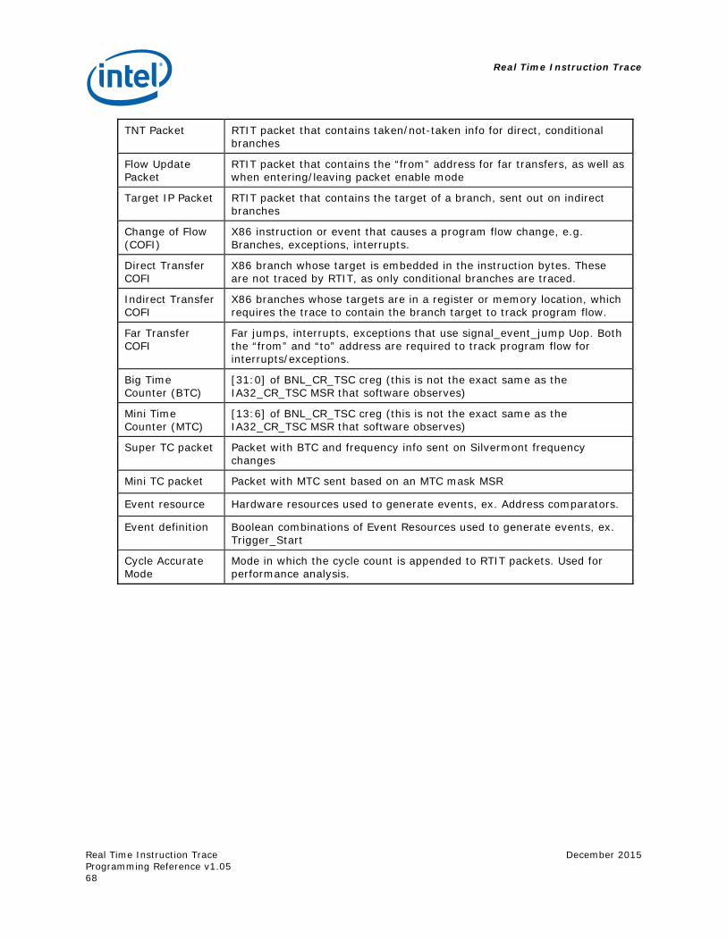
Real Time Instruction Trace
Real Time Instruction Trace Programming Reference v1.05
December 2015
68
TNT Packet RTIT packet that contains taken/not-taken info for direct, conditional branches
Flow Update Packet
RTIT packet that contains the “from” address for far transfers, as well as when entering/leaving packet enable mode
Target IP Packet RTIT packet that contains the target of a branch, sent out on indirect branches
Change of Flow (COFI)
X86 instruction or event that causes a program flow change, e.g. Branches, exceptions, interrupts.
Direct Transfer COFI
X86 branch whose target is embedded in the instruction bytes. These are not traced by RTIT, as only conditional branches are traced.
Indirect Transfer COFI
X86 branches whose targets are in a register or memory location, which requires the trace to contain the branch target to track program flow.
Far Transfer COFI
Far jumps, interrupts, exceptions that use signal_event_jump Uop. Both the “from” and “to” address are required to track program flow for interrupts/exceptions.
Big Time Counter (BTC)
[31:0] of BNL_CR_TSC creg (this is not the exact same as the IA32_CR_TSC MSR that software observes)
Mini Time Counter (MTC)
[13:6] of BNL_CR_TSC creg (this is not the exact same as the IA32_CR_TSC MSR that software observes)
Super TC packet Packet with BTC and frequency info sent on Silvermont frequency changes
Mini TC packet Packet with MTC sent based on an MTC mask MSR
Event resource Hardware resources used to generate events, ex. Address comparators.
Event definition Boolean combinations of Event Resources used to generate events, ex. Trigger_Start
Cycle Accurate Mode
Mode in which the cycle count is appended to RTIT packets. Used for performance analysis.
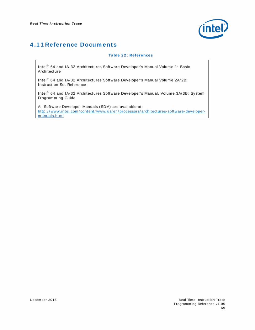
Real Time Instruction Trace
December 2015
Real Time Instruction Trace Programming Reference v1.05
69
4.11 Reference Documents Table 22: References
Intel® 64 and IA-32 Architectures Software Developer’s Manual Volume 1: Basic Architecture
Intel® 64 and IA-32 Architectures Software Developer’s Manual Volume 2A/2B: Instruction Set Reference
Intel® 64 and IA-32 Architectures Software Developer’s Manual, Volume 3A/3B: System Programming Guide
All Software Developer Manuals (SDM) are available at: http://www.intel.com/content/www/us/en/processors/architectures-software-developer-manuals.html
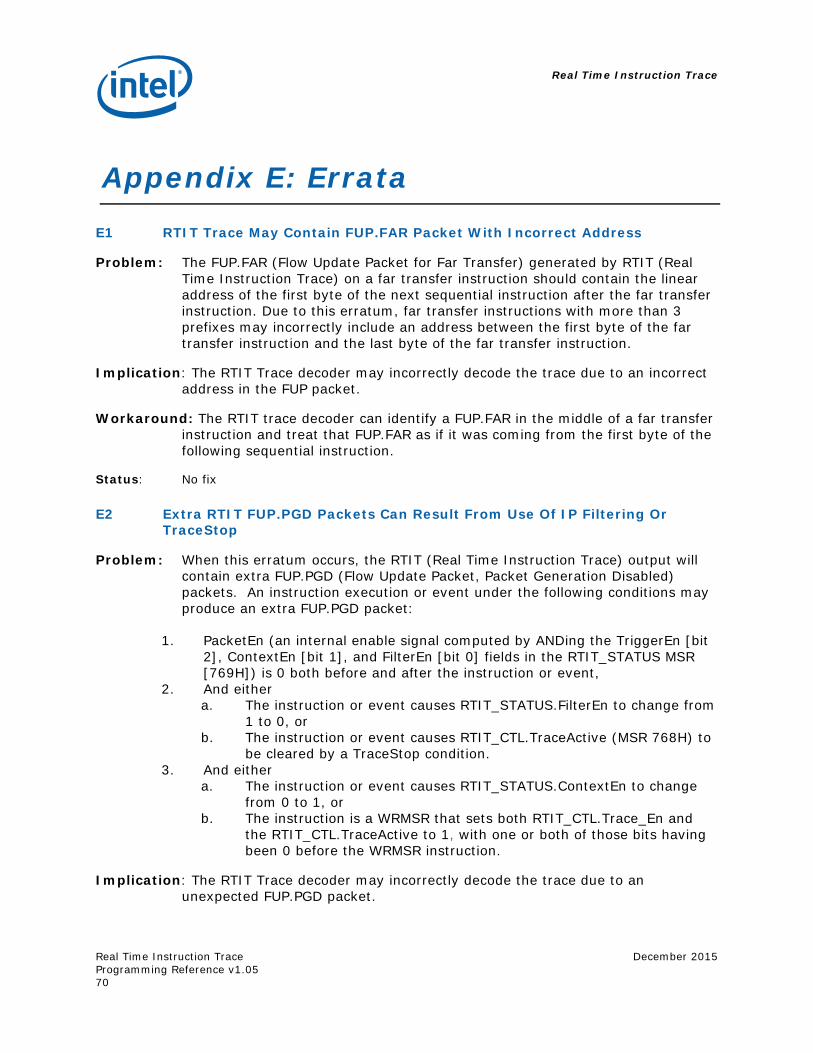
Real Time Instruction Trace
Real Time Instruction Trace Programming Reference v1.05
December 2015
70
Appendix E: Errata E1 RTIT Trace May Contain FUP.FAR Packet With Incorrect Address
Problem: The FUP.FAR (Flow Update Packet for Far Transfer) generated by RTIT (Real Time Instruction Trace) on a far transfer instruction should contain the linear address of the first byte of the next sequential instruction after the far transfer instruction. Due to this erratum, far transfer instructions with more than 3 prefixes may incorrectly include an address between the first byte of the far transfer instruction and the last byte of the far transfer instruction.
Implication: The RTIT Trace decoder may incorrectly decode the trace due to an incorrect address in the FUP packet.
Workaround: The RTIT trace decoder can identify a FUP.FAR in the middle of a far transfer instruction and treat that FUP.FAR as if it was coming from the first byte of the following sequential instruction.
Status: No fix
E2 Extra RTIT FUP.PGD Packets Can Result From Use Of IP Filtering Or TraceStop
Problem: When this erratum occurs, the RTIT (Real Time Instruction Trace) output will contain extra FUP.PGD (Flow Update Packet, Packet Generation Disabled) packets. An instruction execution or event under the following conditions may produce an extra FUP.PGD packet:
1. PacketEn (an internal enable signal computed by ANDing the TriggerEn [bit 2], ContextEn [bit 1], and FilterEn [bit 0] fields in the RTIT_STATUS MSR [769H]) is 0 both before and after the instruction or event,
2. And either a. The instruction or event causes RTIT_STATUS.FilterEn to change from
1 to 0, or b. The instruction or event causes RTIT_CTL.TraceActive (MSR 768H) to
be cleared by a TraceStop condition. 3. And either
a. The instruction or event causes RTIT_STATUS.ContextEn to change from 0 to 1, or
b. The instruction is a WRMSR that sets both RTIT_CTL.Trace_En and the RTIT_CTL.TraceActive to 1, with one or both of those bits having been 0 before the WRMSR instruction.
Implication: The RTIT Trace decoder may incorrectly decode the trace due to an unexpected FUP.PGD packet.
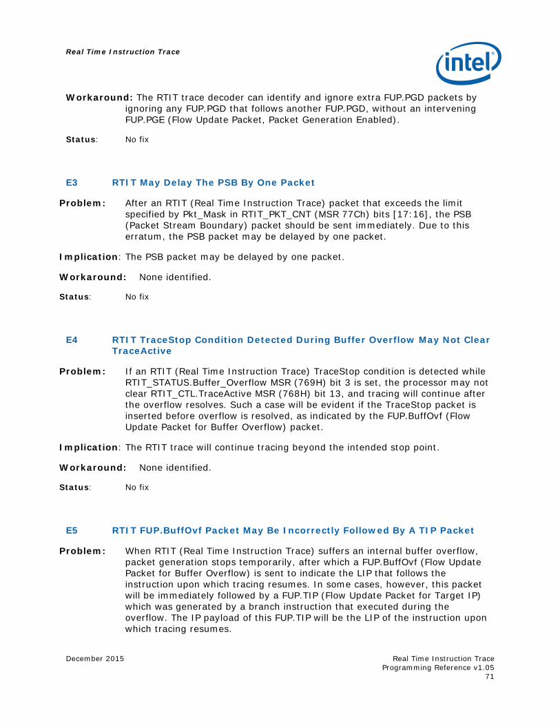
Real Time Instruction Trace
December 2015
Real Time Instruction Trace Programming Reference v1.05
71
Workaround: The RTIT trace decoder can identify and ignore extra FUP.PGD packets by ignoring any FUP.PGD that follows another FUP.PGD, without an intervening FUP.PGE (Flow Update Packet, Packet Generation Enabled).
Status: No fix
E3 RTIT May Delay The PSB By One Packet
Problem: After an RTIT (Real Time Instruction Trace) packet that exceeds the limit specified by Pkt_Mask in RTIT_PKT_CNT (MSR 77Ch) bits [17:16], the PSB (Packet Stream Boundary) packet should be sent immediately. Due to this erratum, the PSB packet may be delayed by one packet.
Implication: The PSB packet may be delayed by one packet.
Workaround: None identified.
Status: No fix
E4 RTIT TraceStop Condition Detected During Buffer Overflow May Not Clear TraceActive
Problem: If an RTIT (Real Time Instruction Trace) TraceStop condition is detected while RTIT_STATUS.Buffer_Overflow MSR (769H) bit 3 is set, the processor may not clear RTIT_CTL.TraceActive MSR (768H) bit 13, and tracing will continue after the overflow resolves. Such a case will be evident if the TraceStop packet is inserted before overflow is resolved, as indicated by the FUP.BuffOvf (Flow Update Packet for Buffer Overflow) packet.
Implication: The RTIT trace will continue tracing beyond the intended stop point.
Workaround: None identified.
Status: No fix
E5 RTIT FUP.BuffOvf Packet May Be Incorrectly Followed By A TIP Packet
Problem: When RTIT (Real Time Instruction Trace) suffers an internal buffer overflow, packet generation stops temporarily, after which a FUP.BuffOvf (Flow Update Packet for Buffer Overflow) is sent to indicate the LIP that follows the instruction upon which tracing resumes. In some cases, however, this packet will be immediately followed by a FUP.TIP (Flow Update Packet for Target IP) which was generated by a branch instruction that executed during the overflow. The IP payload of this FUP.TIP will be the LIP of the instruction upon which tracing resumes.
Real Time Instruction Trace
Real Time Instruction Trace Programming Reference v1.05
December 2015
72
Implication: The spurious FUP.TIP packet may cause the RTIT trace decoder to fail.
Workaround: The RTIT trace decoder should ignore any FUP.TIP packet that immediately follows a FUP.BuffOvf whose IP matches the IP payload of the FUP.BuffOvf.
Status: No fix
E6 RTIT CYC Packet Payload Values May Be Off By 1 Cycle
Problem: When RTIT (Real Time Instruction Trace) is enabled with RTIT_CTL.Cyc_Acc MSR (768H) bit 1 set to 1, all CYC (Cycle Count) packets have a payload value that is one less than the number of cycles that have actually passed. Note that for CYC packets with a payload value of 0, the correct value may be 0 or 1.
Implication: The trace decoder will produce inaccurate performance data when using CYC packets to track software performance.
Workaround: As a partial workaround, the trace decoder should add 1 to the payload value of any CYC packet with a non-zero payload.
Status: No fix
E7 First MTC Packet After RTIT Enable May Be Incorrect
Problem: When RTIT (Real Time Instruction Trace) is enabled, indicated by TriggerEn in bit 2 of the RTIT_STATUS MSR (769H) transitioning from 0 to 1, the first MTC (Mini Time Counter) packet may be sent at the wrong time.
Implication: The RTIT trace decoder will make incorrect assumptions about the TSC value based on an asynchronous MTC packet.
Workaround: The RTIT trace decoder should ignore the first MTC that follows trace enabling.
Status: No fix
E8 Some RTIT Packets Following PSB May be Sent Out of Order or Dropped
Problem: When a complex micro-architectural condition occurs concurrently with the generation of a RTIT (Real-Time Instruction Trace) PSB (Packet Stream Boundary) packet, the packets that immediately follow the PSB could precede or overwrite some older packets. This erratum applies to no more than 21 packets immediately following the PSB.
Implication: The RTIT packet output immediately following a PSB may not accurately reflect software behavior, and may result in an RTIT decoder error.

Real Time Instruction Trace
December 2015
Real Time Instruction Trace Programming Reference v1.05
73
Workaround: None identified.
Status: No fix