Real-Time Estimation of Pathological Tremor Parameters...
21
Sensors 2010, 10, 2129-2149; doi:10.3390/s100302129 OPEN ACCESS sensors ISSN 1424-8220 www.mdpi.com/journal/sensors Article Real-Time Estimation of Pathological Tremor Parameters from Gyroscope Data Juan A. Gallego ⋆ , Eduardo Rocon, Javier O. Roa, Juan C. Moreno and Jos´ e L. Pons Bioengineering Group, Consejo Superior de Investigaciones Cient´ ıficas, CSIC, Ctra. Campo Real, km 0.2 La Poveda, 28500, Arganda del Rey, Spain; E-Mails: [email protected] (E.R.); [email protected] (J.O.R.); [email protected] (J.C.M.); [email protected] (J.L.P.) ⋆ Author to whom correspondence should be addressed; E-Mail: [email protected]; Tel.: +34-918711900; Fax: +34-918717050. Received: 25 January 2010; in revised form: 26 February 2010 / Accepted: 1 March 2010 / Published: 16 March 2010 Abstract: This paper presents a two stage algorithm for real-time estimation of instanta- neous tremor parameters from gyroscope recordings. Gyroscopes possess the advantage of providing directly joint rotational speed, overcoming the limitations of traditional tremor recording based on accelerometers. The proposed algorithm first extracts tremor patterns from raw angular data, and afterwards estimates its instantaneous amplitude and frequency. Real-time separation of voluntary and tremorous motion relies on their different frequency contents, whereas tremor modelling is based on an adaptive LMS algorithm and a Kalman filter. Tremor parameters will be employed to drive a neuroprosthesis for tremor suppression based on biomechanical loading. Keywords: tremor; inertial sensors; MEMS gyroscope; tremor modelling; voluntary move- ment estimation; adaptive signal processing; Kalman filter; real-time estimation; neuropros- thesis 1. Introduction Tremor is defined as a rhythmic oscillation of a body part [1]. Despite we all have a small component of tremor, the so-called physiological tremor, there exist pathologies with very disabling forms of tremor. Pathological tremor constitutes the most common movement disorder and is continuously increasing its
Transcript of Real-Time Estimation of Pathological Tremor Parameters...

Sensors 2010, 10, 2129-2149; doi:10.3390/s100302129
OPEN ACCESS
sensorsISSN 1424-8220
www.mdpi.com/journal/sensors
Article
Real-Time Estimation of Pathological Tremor Parameters fromGyroscope DataJuan A. Gallego ⋆, Eduardo Rocon, Javier O. Roa, Juan C. Moreno and Jose L. Pons
Bioengineering Group, Consejo Superior de Investigaciones Cientıficas, CSIC, Ctra. Campo Real,km 0.2 La Poveda, 28500, Arganda del Rey, Spain; E-Mails: [email protected] (E.R.);[email protected] (J.O.R.); [email protected] (J.C.M.); [email protected] (J.L.P.)
⋆ Author to whom correspondence should be addressed; E-Mail: [email protected];Tel.: +34-918711900; Fax: +34-918717050.
Received: 25 January 2010; in revised form: 26 February 2010 / Accepted: 1 March 2010 / Published:16 March 2010
Abstract: This paper presents a two stage algorithm for real-time estimation of instanta-neous tremor parameters from gyroscope recordings. Gyroscopes possess the advantage ofproviding directly joint rotational speed, overcoming the limitations of traditional tremorrecording based on accelerometers. The proposed algorithm first extracts tremor patternsfrom raw angular data, and afterwards estimates its instantaneous amplitude and frequency.Real-time separation of voluntary and tremorous motion relies on their different frequencycontents, whereas tremor modelling is based on an adaptive LMS algorithm and a Kalmanfilter. Tremor parameters will be employed to drive a neuroprosthesis for tremor suppressionbased on biomechanical loading.
Keywords: tremor; inertial sensors; MEMS gyroscope; tremor modelling; voluntary move-ment estimation; adaptive signal processing; Kalman filter; real-time estimation; neuropros-thesis
1. Introduction
Tremor is defined as a rhythmic oscillation of a body part [1]. Despite we all have a small componentof tremor, the so-called physiological tremor, there exist pathologies with very disabling forms of tremor.Pathological tremor constitutes the most common movement disorder and is continuously increasing its
Sensors 2010, 10 2130
prevalence with ageing. Although not life threatening, tremor often causes social embarrassment andfunctional disability; in fact, 65% of patients suffering from upper limb tremor report serious difficultiesin performing their activities of daily living [2].
Regarding its aetiology, tremors are caused by the different combinations of four different mech-anisms: (1) mechanically induced oscillations, (2) oscillations due to reflexes, (3) oscillations due tocentral neuronal circuits, and (4) oscillations because of disturbed feedback or feedforward loops [1].However, understanding of the origins of tremors is far from complete.
Pathological tremors are typically classified by position/motor behavior, which reflects under whichcircumstances tremor appears. According to this criterium, tremor falls into three categories: rest, pos-tural and kinetic tremor [3].
Current strategies on the treatment of tremors are based on drugs, surgery (thalatomy), or deep brainstimulation. The last two options are typically employed in patients refractory to drugs [4]. How-ever, (1) tremor is not managed satisfactorily in 25 % of patients, (2) drugs used often induce sideeffects, and (3) neurosurgery is associated with hemorrhages and psychiatric manifestations, such as anincreased suicidal tendency [5]. These reasons make research on new therapeutic options to managetremor mandatory.
In this context, functional compensation of pathological tremors via biomechanical loading has ap-peared as a promising alternative. It is based on the fact that most types of tremors change their char-acteristics (amplitude and frequency) when the apparent limb impedance is modified, for example, ap-plying a force or adding a mass [6–8]. In particular, it has been clinically demonstrated that increaseof damping and/or inertia in the upper limb leads to an effective tremor reduction [2,8]. In [9], theauthors have validated, both functionally and clinically, the concept of tremor suppression by meansof a wearable robot that applies biomechanical loads in the upper limb. To achieve satisfactory tremorsuppression, the wearable robot must leave concomitant voluntary movement unmodified, compensatingfor tremor. In this regard, real-time estimation of instantaneous tremor parameters becomes fundamen-tal to develop robust orthotic or neuroprosthetic solutions for tremor suppression. The present work iscarried out in the framework of EU project TREMOR (ICT–2007–224051), which aims at developinga soft wearable robot for tremor suppression based on a textile substrate. Tremor suppression will beachieved through the application of selective biomechanical loads by means of Functional ElectricalStimulation (FES). FES constitutes a means of activating motoneurons or reflex pathways by stimu-lating sensory nerve fibers [10]; it therefore allows for employing human muscles as actuators for awearable robot [11]. The algorithm presented here will be employed to derive tremor characteristics,in order to generate adequate stimulation patterns that counteract tremor, leaving concomitant voluntarymovement unaffected.
Inertial sensors technologies constitute a breakthrough and optimal approach to worn sensors in mo-tion analysis [12], and wearable robotics [13]. Advances in microelectromechanical systems (MEMS)permitted to develop miniaturized low cost sensors that measure changes in velocity, position and accel-eration [13]. Low size and weight allow for wearability, overcoming the limitation of traditional motioncapture systems, based on optic sensors and markers, to work in reduced areas. The most spread types ofMEMS sensors are solid state accelerometers, gyroscopes, and magnetometers. MEMS accelerometers,and most recently gyroscopes, have been employed to analyze tremorous movements.
Sensors 2010, 10 2131
Other solutions for kinematic recording of tremors found in the literature are instrumented, ad-hocdevices, such as the instrumented glove [14], or digitizing tablets [15]. Works that study tremor bygenerating it with an actuated mechanical setup, employ specific sensors technologies such as Hall effecttransducers [16], or piezoelectric accelerometers [17], to measure it.
Regarding tremor monitoring with MEMS inertial sensors, accelerometers constitute the most spreadalternative [18,19], although it is not the most adequate, [20]. In fact, accelerometers measure limb ori-entation with respect to gravity, but their measurement is corrupted by voluntary movements, decreasingaccuracy dramatically. Moreover, accelerometers measure linear acceleration, whereas articular motionsare rotational about joints. Accelerometer data is typically considered to be compound of three factors:linear acceleration, gravity, and white additive noise [21]. No analytic model to distinguish betweenaccelerometer data due to acceleration and gravity is available, although the most common approach isto model acceleration changes as a low pass filter [21,22], or to separate both components by means ofa FIR low pass filter [23]. On the contrary, solid state gyroscopes provide a direct measurement of arotational movement, uninfluenced by gravity [24], but affected by a characteristic low frequency bias.This bias is traditionally thought of being caused by the effects of temperature and mechanical wear [21],although our experiments demonstrate that it is only correlated with temperature, as in next Section.
Most of currently existing tremor estimation algorithms have been developed for cancelling physio-logical tremor in human-machine interfaces. Physiological tremor has another aetiology than patholog-ical tremors, and possesses also different characteristics: it is barely visible to the unaided eye, and hasfrequency between 8 and 12 Hz [25]. Physiological tremor is only symptomatic during high precisiontasks, thus it is typically employed during hand held surgery. According to this, successful algorithmsfor cancelling physiological tremors such as the classical Weighted frequency Fourier Linear Combiner(WFLC) [16], Bandlimited Multiple Fourier Linear Combiner (BMFLC) [17], or Double adaptive BM-FLC [26], may not constitute the optimal solution for estimation of pathological tremor parameters. Infact, in [9], Rocon and colleagues employ a preliminary filtering stage that eliminated volitional motionfrom the input signal before feeding it into a WFLC, which was employed to track pathological tremor.A similar approach has been recently described in [27].
In this paper, we present a two stage algorithm that estimates instantaneous tremor parameters fromwearable gyroscope data. As above mentioned, information about current tremor amplitude and fre-quency will be employed to drive a neuroprosthesis for tremor suppression based on application of se-lective biomechanical loads. We employ MEMS gyroscopes to record joint kinematics. Next, tremorouspatterns are extracted from the recorded motion, based on the frequency distribution of voluntary andtremorous components of movement. The second stage of the algorithm estimates tremor amplitude andfrequency from the tremorous component of joint motion. Robust, precise and low delay estimation oftremor parameters is achieved: average amplitude estimation error is 0.001± 0.002 rad/s, and frequencyestimation agrees with spectrograms.
This paper is organized as follows. First, Section 2 presents selection of sensors, patients, and clin-ical and functional tests to be recorded. Next, in Section 3, we introduce the architecture of our twostage algorithm, and a series of estimators that will be evaluated for voluntary movement estimationand tremor modelling (each of the stages). The performance of these algorithms when tracking tremorparameters in real data is compared in Section 4; which serves to define an optimal architecture for the
Sensors 2010, 10 2132
algorithm. Finally, we end the paper with a discussion on the results, and some conclusions summarizingmajor achievements.
2. Methods
In order to assess time varying tremor parameters, we record hand motion by measuring wrist flexion-extension. We decide to measure wrist tremor because: (1) tremors are more explicit at distal joints [1],(2) wrist tremor has the largest impact on disability [28], and (3) it constitutes, together with fingertremor, the most studied tremor in clinical literature.
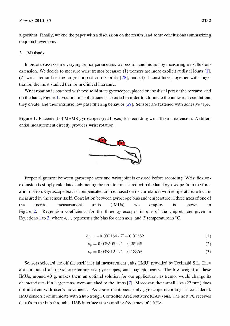
Wrist rotation is obtained with two solid state gyroscopes, placed on the distal part of the forearm, andon the hand, Figure 1. Fixation on soft tissues is avoided in order to eliminate the undesired oscillationsthey create, and their intrinsic low pass filtering behavior [29]. Sensors are fastened with adhesive tape.
Figure 1. Placement of MEMS gyroscopes (red boxes) for recording wrist flexion-extension. A differ-ential measurement directly provides wrist rotation.
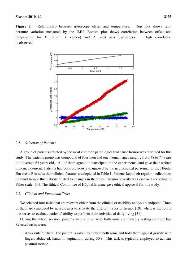
Proper alignment between gyroscope axes and wrist joint is ensured before recording. Wrist flexion-extension is simply calculated subtracting the rotation measured with the hand gyroscope from the fore-arm rotation. Gyroscope bias is compensated online, based on its correlation with temperature, which ismeasured by the sensor itself. Correlation between gyroscope bias and temperature in three axes of one ofthe inertial measurement units (IMUs) we employ is shown inFigure 2. Regression coefficients for the three gyroscopes in one of the chipsets are given inEquations 1 to 3, where baxis represents the bias for each axis, and T temperature in °C.
bx = −0.000154 · T + 0.00562 (1)
by = 0.008506 · T − 0.35245 (2)
bz = 0.038312 · T − 0.13358 (3)
Sensors selected are off the shelf inertial measurement units (IMU) provided by Technaid S.L. Theyare compound of triaxial accelerometers, gyroscopes, and magnetometers. The low weight of theseIMUs, around 40 g, makes them an optimal solution for our application, as tremor would change itscharacteristics if a larger mass were attached to the limbs [7]. Moreover, their small size (27 mm) doesnot interfere with user’s movements. As above mentioned, only gyroscope recordings is considered.IMU sensors communicate with a hub trough Controller Area Network (CAN) bus. The host PC receivesdata from the hub through a USB interface at a sampling frequency of 1 kHz.
Sensors 2010, 10 2133
Figure 2. Relationship between gyroscope offset and temperature. Top plot shows tem-perature variation measured by the IMU. Bottom plot shows correlation between offset andtemperature for X (blue), Y (green) and Z (red) axis gyroscopes. High correlationis observed.
0 0.5 1 1.5 2 2.5 330
40
50
Time (min)
Tem
pera
ture
(ºC
)
32 34 36 38 40 42 44 46 48 50−0.1
0
0.1
0.2
0.3
0.4
0.5
0.6
Temperature (ºC)
Gyr
osco
pes
Bia
s (r
ad/s
)
2.1. Selection of Patients
A group of patients affected by the most common pathologies that cause tremor was recruited for thisstudy. The patients group was compound of four men and one woman, ages ranging from 48 to 74 yearsold (average 63 years old). All of them agreed to participate in the experiments, and gave their writteninformed consent. Patients had been previously diagnosed by the neurological personnel of the HopitalErasme at Brussels; their clinical features are depicted in Table 1. Patients kept their regular medications,to avoid tremor fluctuations related to changes in therapies. Tremor severity was assessed according toFaher scale [30]. The Ethical Committee of Hoptial Erasme gave ethical approval for this study.
2.2. Clinical and Functional Tasks
We selected four tasks that are relevant either from the clinical or usability analysis standpoint. Threeof them are employed by neurologists to activate the different types of tremor [19], whereas the fourthone serves to evaluate patients’ ability to perform their activities of daily living [31].
During the whole session, patients were sitting, with both arms comfortably resting on their lap.Selected tasks were:
1. Arms outstretched: The patient is asked to elevate both arms and hold them against gravity withfingers abducted, hands in supination, during 30 s. This task is typically employed to activatepostural tremor.

Sensors 2010, 10 2134
2. Finger to nose: The patient is asked to alternatively touch his nose and knee with the tip of his/herfinger during 30 s. The patient must keep contact with nose and knee during a few seconds. Thistask is typically used to activate kinetic tremor.
3. Rest: The patient is asked to keep both arms resting on the lap during 30 s. The elbow is flexedaround 90◦. This tasks is typically used to activate rest tremor.
4. Pouring water into a glass: The patient is asked to pour 20 cl water from a standard bottle into aregular glass. The patient could choose how to perform the task, i.e., how to hold the bottle andthe glass. This task is selected for functional and usability analysis.
Table 1. Clinical features of enroled patients.
Patient number Medical History Tremor Body segments affected Frequency Grade1
01 Essential TremorPostural Right upper limb 7 Hz 2
Kinetic Right upper limb 4 Hz 2
02 Paraneoplastic SyndromeKinetic Upper/lower limbs 5–6 Hz 1,2
Postural Right/left inch 2–3 Hz 1
03 Idiophatic ParkinsonRest Upper limbs 3–4 Hz 1,3
Postural Left hand 6 Hz 1
04 Extrapyramidal SyndromeRest Upper limbs 3–4 Hz 2
Postural Upper limbs 3–4 Hz 1
05 Essential TremorPostural Right upper limb 7 Hz 2
Kinetic Upper limbs 4 Hz 2
1 If there are two figures the first one refers to the right limb and the second one to the left limb. If not,
tremor severity is the same for both limbs. The grades are: 0: Absent, 1: Discrete and infrequent, not
disturbing for the patient, 2: Mild, tremor amplitude is discrete but persistent, or tremor amplitude is
mild but its presence is intermittent, 3: Intense, the tremor interferes in some activities, its amplitude
is mild but it appears most of the time, 4: Severe, the tremor interferes in most of the chores, its
amplitude is high, and it appears most of the time.
3. Real-Time Estimation of Instantaneous Tremor Parameters
This section presents our two stage algorithm for real-time modelling of tremor. It relies on twoassumptions: (1) pathological tremors and voluntary motions have different frequency distributions, and(2) pathological tremor constitutes, from a signal processing standpoint, additive noise superimposed tovolitional movement [32].
Sensors 2010, 10 2135
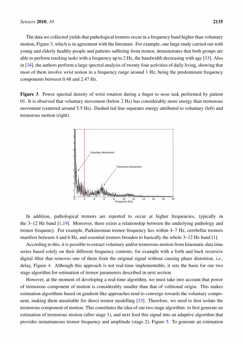
The data we collected yields that pathological tremors occur in a frequency band higher than voluntarymotion, Figure 3, which is in agreement with the literature. For example, one large study carried out withyoung and elderly healthy people and patients suffering from tremor, demonstrates that both groups areable to perform tracking tasks with a frequency up to 2 Hz, the bandwidth decreasing with age [33]. Alsoin [34], the authors perform a large spectral analysis of twenty four activities of daily living, showing thatmost of them involve wrist notion in a frequency range around 1 Hz, being the predominant frequencycomponents between 0.48 and 2.47 Hz.
Figure 3. Power spectral density of wrist rotation during a finger to nose task performed by patient01. It is observed that voluntary movement (below 2 Hz) has considerably more energy than tremorousmovement (centered around 5.5 Hz). Dashed red line separates energy attributed to voluntary (left) andtremorous motion (right).
0 2 4 6 8 10 12 14 16 18 200
0.2
0.4
0.6
0.8
1
1.2
1.4
1.6
1.8
2
Frequency (Hz)
Voluntary Movement
Tremorous Movement
In addition, pathological tremors are reported to occur at higher frequencies, typically inthe 3–12 Hz band [1,19]. Moreover, there exists a relationship between the underlying pathology andtremor frequency. For example, Parkinsonian tremor frequency lies within 4–7 Hz, cerebellar tremorsmanifest between 4 and 6 Hz, and essential tremors broaden to basically the whole 3–12 Hz band [1].
According to this, it is possible to extract voluntary and/or tremorous motion from kinematic data timeseries based solely on their different frequency contents, for example with a forth and back recursivedigital filter that removes one of them from the original signal without causing phase distortion, i.e.,delay, Figure 4. Although this approach is not real-time implementable, it sets the basis for our twostage algorithm for estimation of tremor parameters described in next section.
However, at the moment of developing a real-time algorithm, we must take into account that powerof tremorous component of motion is considerably smaller than that of volitional origin. This makesestimation algorithms based on gradient like approaches tend to converge towards the voluntary compo-nent, making them unsuitable for direct tremor modelling [33]. Therefore, we need to first isolate thetremorous component of motion. This constitutes the idea of our two stage algorithm: to first generate anestimation of tremorous motion (after stage 1), and next feed this signal into an adaptive algorithm thatprovides instantaneous tremor frequency and amplitude (stage 2), Figure 5. To generate an estimation

Sensors 2010, 10 2136
of tremor, we employ a tracking algorithm to estimate the voluntary component of motion. Next, basedon the fact that tremor alters volitional motion in an additive manner [32], we remove the estimatedvoluntary movement from the input signal, obtaining an estimation of tremor.
Figure 4. Separation of voluntary and tremorous components of movement by means ofrecursive digital filters. Top left figure shows the original signal (black) and voluntarymovement (red) obtained with a zero phase low pass filter, fc = 2 Hz. Bottom leftplot shows tremorous movement obtained by subtracting voluntary movement from the orig-inal signal. Right plots show power spectral densities of voluntary (top) and tremorouscomponents (bottom).
5 10 15 20time (s)
Total motionVoluntary Motion
5 10 15 20time (s)
Tremorous Motion
0 5 10 15 200
0.2
0.4
0.6
0.8
frequency (Hz)
Am
plitu
de S
pect
rum
(ra
d2 /s)
0 5 10 15 200
0.05
0.1
0.15
0.2
frequency (Hz)
Am
plitu
de S
pect
rum
(ra
d2 /s)
Tremorous Motion
Voluntary Motion
Figure 5. Block diagram of the two stage algorithm for real-time estimation of tremor parameters. First,we generate an estimation of the voluntary component of motion, which subtracted from the total move-ment yields an estimate of tremor. Afterwards, in stage two, and adaptive algorithm tracks instantaneoustremor parameters.
Voluntary Movement
Estimation
Total Motion Voluntary MotionTremor tracking
Tremor Amplitude
Tremor Frequency
-
This section reviews a series of algorithms that are employed to develop the two stage algorithm. First,we present a number of techniques to track voluntary movement based on its lower frequency content.Next, we introduce two adaptive algorithms that track an input signal based on Fourier modelling and theLeast Mean Square (LMS) recursion, a gradient-like approach [35], and a Kalman Filter that estimatespathological tremor amplitude.

Sensors 2010, 10 2137
3.1. Stage 1. Voluntary Motion Tracking
Two types of tracking algorithms for real-time estimation of voluntary movement will be evaluated.As discussed above, voluntary movements are assumed to be performed between 0 and 2 Hz. Therefore,the tracking algorithm must be designed to neglect any component of the movement over 2 Hz.
Voluntary movement is modelled as a first order process. If we consider a Taylor series that representsvoluntary movement, we can neglect the second derivative x if either the sampling period Ts or theacceleration itself are small, Equation 4. In our case both assumptions are satisfied: the sampling periodis 1 ms, and the maximum of x is 2.54 · 10−4 rad·s−3, 4 orders of magnitude smaller than averageangular velocity.
x(t) = x(tn) + Tsx(tn) +T 2s
2x(tn) + ... (4)
g–h Filters g–h filters are simple recursive filters that estimate future position and velocity of a variablebased on first order model of the process. Measurements are used to correct these predictions, minimiz-ing the estimation error. Traditional applications of g–h filters are radar tracking andaeronautics [36]. The general form of a g–h filter is:
xk,k = xk,k−1 + gk(yk − xk,k−1) (5)
xk,k = xk,k−1 +hk
Ts(yk − xk,k−1) (6)
xk+1,k = xk,k + Tsxk,k (7)
xk+1,k = xk,k (8)
Equations 5 and 6 are designated as update, tracking, or filtering equations. They estimate the currentposition and velocity of the variable, xk,k, xk,k, based on previous predicted position and velocity, xk,k−1,xk,k−1, taking current measurement yk into account. Confidence on measures is weighted by gains gk
and hk. Equations 7 and 8 are called prediction equations because they provide a prediction of futureposition and velocity, xk+1,k, xk+1,k, based on first order dynamic model of the variable. As g–h trackersconsider a constant velocity model, predicted velocity xk+1,k is equal to the current one, xk,k.
g–h filters are affected by two error sources [36]: (1) the lag, dynamic, bias or systematic error, whichis related to the constant velocity assumption, and (2) the measurement error, which is inherent to thesensor and measurement process. Typically, the smaller gk and hk are, the larger is the dynamic errorand the smaller are the measurement errors [36]. Therefore, in designing a g–h tracking filter there isa degree of freedom in choice of the relative magnitude of the measurement and dynamic errors. Tosimplify the selection of gains, we consider two filters that are optimal in some sense. These filters arethe Benedict–Bordner Filter and the Critically Dampened filter, described next.

Sensors 2010, 10 2138
• Benedict–Bordner Filter: The Benedict–Bordner Filter (BBF) minimizes the total transient error,defined as the weighted sum of the total transient error and the variance of prediction error due tomeasurement noise errors [37]. The BBF is the constant g–h filter that satisfies:
h =g2
2− g(9)
As Equation 9 relates g and h, the BBF has one degree of freedom. Because for g–h filters in-creasing the value of g diminishes the transient error, the larger g, the higher frequencies the BBFtracks.
• Critically Dampened Filter: The Critically Dampened Filter (CDF) minimizes the least squaresfitting line of previous measurements [36], giving old data lesser significance when forming thetotal error sum. This is achieved with weight factor θ. Parameters in the g–h filter are related by:
g = 1− θ2 (10)
h = (1− θ)2
Selection of filter gain for the CDF is analogous to that for the BBF.
Kalman Filter The Kalman filter (KF) is the most widespread estimation algorithm, and is employedin a large number of applications. We implement a KF that tracks voluntary movement modelled as afirst order process, Equation 4. Therefore, state vector x(t) is composed by the variable to be estimated,and its derivative. The problem is formulated as:
xk,k−1 =
[1 Ts
0 1
]xk−1,k−1 (11)
yk =[1 0
]xk−1,k−1 (12)
Covariance matrices are defined taking into account the following considerations:
1. Measurement noise covariance R(k): as voluntary motion is the variable we are tracking, tremoris assumed to be sensor noise. The value of the measurement noise covariance is considered to bethe average covariance of isolated tremor data; therefore R(k) = σ2
ω = 0.0643 rad2·s −2.
2. Process noise covariance Q(k): we hypothesize that process noise is related to voluntary motionchanges due to tremor. A piecewise constant acceleration model is considered, [38]. This modelassumes that voluntary movement undergoes constant and uncorrelated acceleration changes be-tween samples in the form of:
Q = σ2ν
[T 4s
4T 3s
2T 3s
2T 2s
](13)
To select the variance of the random velocity component, σ2ν , we follow the recommendation
in [38]: 0.5 ·maxx ≤ |σν | ≤ maxx. The second derivative of the raw recorded motion yields thatmaxx = 0.1042 rad·s−3.
Sensors 2010, 10 2139
3.2. Stage 2. Tremor Modelling
State of the art tremor modelling algorithms rely on a time-varying Fourier series, which parametersare estimated recursively. Adaptation to the input signal is based on the LMS algorithm developedby Widrow [35]. As the LMS technique is a descend method that relies on a special estimate of thegradient [35], high energy voluntary motion must be removed first, to ensure proper tremor tracking.The first part of the two stage algorithm accomplishes this task, Figure 5.
We evaluate the performance of two algorithms originally developed to track physiological tremor,and of a Kalman Filter we have developed to estimate tremor amplitude, the parameter that is more proneto change during the execution of a task, while tremor frequency keeps within a ±1.5 Hz interval aroundtremor frequency [39].
Weighted Frequency Fourier Linear Combiner The Weighted Frequency Fourier Linear Combiner(WFLC) is the most widespread algorithm for tremor modelling. It consists in an extension of theclassical noise canceller presented in [35], the Fourier Linear Combiner [40], which also tracks frequencyof the input signal based on a LMS recursion. Therefore, the WFLC adapts in real-time its amplitude,frequency and phase [16]:
xrk =
sin(r∑k
t=1 ω0t
), 1 ≤ r ≤ M
cos(r∑k
t=1 ω0t
), M + 1 ≤ r ≤ 2M
(14)
εk = sk −WTkXk − µb (15)
ω0k+1= ω0k + 2µ0εk
M∑r=1
r (wrkxM+rk − wM+rkxrk) (16)
Wk+1 = Wk + 2µ1εkXk (17)
Equation 14 represents the time varying sinusoidal terms of the Fourier Series. Equation 15 definesthe error to be minimized by the LMS recursion. Equations 16 and 17 represent frequency and amplitudeadaptation. The WFLC has four parameters: the number of harmonics of the model, M , the amplitudeand frequency adaptation gains, µ0, and µ1, and a bias weight µb that is included to compensate forlow frequency errors [16,41]. The number of harmonics is typically fixed to 1, the other parameters areselected based on experimental data.
Bandlimited Multiple Fourier Linear Combiner The Bandlimited Multiple Fourier Linear Com-biner (BMFLC) is a more recent algorithm derived from the FLC. It emerged to compensate for thelimitations of the WFLC to track physiological tremor when two constituent frequencies [25] are clearlyevident, or when frequency variations occur abruptly [17]. The BMFLC consists in a bank of FLCsthat track the input signal based on multiple frequency components. Therefore, each FLC adapts itsamplitude to the input signal, although its frequency remains constant.
The performance of the BMFLC relies on the multiple fixed frequencies it can track. An interval isthus defined with the lower and upper frequency of the FLCs bank, ω0, and ωf . The number of FLCs inbetween is defined by parameter G. The BMFLC is formulated as follows [17]:
Sensors 2010, 10 2140
xrk =
{sin
(ω0 +
(ωf − ω0
)r−1G+1
k), 1 ≤ r ≤ M
cos(ω0 + (ωf − ω0)
r−1G+1
k), M + 1 ≤ r ≤ 2M
(18)
εk = sk −WTkXk − µb (19)
Wk+1 = Wk + 2µεkXk (20)
Equation 18 represents the sinusoidal terms of the Fourier Series. Equation 19 defines the error to beminimized by the LMS recursion. Equation 20 represents amplitude adaptation. The BMFLC has sixparameters: the number of harmonics of each FLC model, M , amplitude adaptation gain, µ, the lowerand upper frequency of the FLC bank, ω0, and ωf , and the number of filters in between, G. A bias weightµb is also included to compensate for low frequency errors [16].
Although the BMFLC is not conceived as a frequency tracking algorithm, we developed an equationto estimate the current frequency of the input signal, Equation 21. Frequency estimation is obtained byweighting the contribution of each FLC to amplitude adaptation. For a first order Fourier series, it isexpressed as:
ωk =L∑
r=0
(a2r + b2r)ωr∑Lr=0 (a
2r + b2r)
(21)
Kalman Filter The WFLC and BMFLC algorithms provide adaptation to the input signal based onspecial estimates of the gradient. On the contrary, Kalman Filter (KF) constitutes the optimal solution forestimation problems, in the sense it minimizes the covariance of a posteriori estimation error. Thereforethe performance of WFLC and BMFLC, overall in terms of amplitude estimation, as it is the parameterthat varies the most, can be enhanced using an adequate KF. In a similar manner to WFLC, we defineour KF as:
ω0,k,k−1
Ak,k−1
Bk,k−1
trk,k−1
=
1 0 0 0
0 1 0 0
0 0 1 0
0 cos(ω0,k,k−1) sin(ω0,k,k−1) 0
ω0,k−1,k−1
Ak−1,k−1
Bk−1,k−1
trk−1,k−1
(22)
yk =[0 0 0 1
]xk−1,k−1 (23)
where A and B represent the amplitude of the sinusoidal terms of a first order Fourier series, and ω0 thecurrent tremor frequency. As tremor frequency suffers slow changes, and varies in a ±1.5 Hz intervalaround a characteristic frequency that depends on the patient, [39], WFLC frequency estimation is em-ployed. Therefore we define a cascade filter that consists on a WFLC that tracks tremor frequency, andfeds it into the Kalman Filter that estimates tremor amplitude.
Covariance matrices are adjusted as follows:
1. Measurement noise covariance R(k) = σ2τ , which has only slight impact on transient duration.
2. Process noise covariance is defined as Q(k) = diag(q1,1, q2,2, q3,3, q4,4), because state variables areconsidered to be mutually independent.

Sensors 2010, 10 2141
4. Results
This section presents evaluation of the algorithms described in previous section for both voluntarymotion tracking, and estimation of tremor parameters. The idea is to find a unique filter setup thatprovides accurate tracking of instantaneous tremor parameters for every patient and task. To do so, first,we present the figure of merit that will be employed to tune each algorithm, and compare the performanceof different candidates. Next, we summarize the results obtained with each of them.
4.1. Evaluation of Voluntary Movement Tracking Algorithms
The Kinematic Tracking Error (KTE) evaluates the smoothness, response time, and execution time ofa tracking algorithm, [41]. It is expressed mathematically as:
KTE =√
φ2|b∗| + σ2
|b∗| (24)
where φ|b∗| and σ2|b∗| are the mean and variance of the absolute estimation error, b∗ = |yk − xk+1,k|,
respectively. The former measures how fast the algorithm is capable of reacting when the velocitychanges, whereas the latter quantifies the smoothness or filtering of the estimated variable [41]. Offlinevoluntary motion estimation obtained with a forth and back recursive filter is employed as the referencesignal the estimators should track. This technique consists in filtering input data in both the forward andreverse directions; after filtering in the forward direction, the algorithm reverses the filtered sequenceand runs it back through the filter, which yields precisely zero-phase distortion.
First, we present results obtained with the optimal parameter(s) for each of the voluntary movementestimation algorithms presented in Section 3.1 The condition to select the optimal parameter(s) for eachalgorithm is to find the tuning that minimizes the KTE between filter estimation of voluntary motion andzero phase (off-line) recursive estimation of voluntary movement. Optimal filters are:
• Benedict–Bordner Filter with g = 0.018.
• Critically Dampened Filter with θ = 0.990.
• Kalman Filter with σ2ω = 0.0643 and σ2
ν = 0.1042.
The KTE is employed next to compare their relative performance. Table 2 summarizes KTE per kindof task and patient, for the optimal setup for the three algorithms. We observe that among the BBF, CDF,and KF, the CDF with θ = 0.990 performs the best when tracking voluntary movement, as it providesthe least KTE for all tasks; thus it is the approach we select for the first stage of the algorithm.
Figure 6 shows an example of CDF and BBF estimation of voluntary movement from raw gyroscoperecording, during an arms outstretched task performed by patient 01. We observe that BBF estimation isless smooth than that of the CDF for a similar adaptation to transitory changes.

Sensors 2010, 10 2142
Table 2. Kinematic Tracking Error (rad/s) for voluntary movement tracking algorithms organized bytask. Table provides mean ± standard deviation.
Algorithm Arms Outstretched Finger to nose Rest Water into a glass
Benedict–Bordner Filter 0.194± 0.058 0.400± 0.134 0.147± 0.091 0.291± 0.083
Critically Dampened Filter 0.121± 0.053 0.372± 0.118 0.134± 0.081 0.264± 0.073
Kalman Filter 0.169± 0.100 0.378± 0.143 0.174± 0.129 0.312± 0.124
Figure 6. Comparison between CDF and BBF estimation of voluntary movement from raw gyroscopedata during an arms outstretched test performed by patient 01.
15 16 17 18 19 20 21 22 23 24 25
−0.5
−0.4
−0.3
−0.2
−0.1
0
0.1
0.2
0.3
0.4
time (s)
angu
lar
velo
city
(ra
d/s)
raw motionCDF estimationBBF estimation
4.2. Evaluation of Tremor Modelling Algorithms
An optimal figure of merit to evaluate tremor estimation algorithms must consider the physical natureof the estimation error; for example if it originates from phase difference between real and estimatedtremor, or estimation overshoots and undershoots. Traditional use of root mean square error (RMSE)suffers from these problems: (1) because errors due to undershoots and overshoots posses large power,which make them overshadow errors from interest, and (2) because the presence of delays affects theRMSE severely, although it does not necessarily indicate poorperformance [42]. In this regard, the so-called filtered mean square error with delay correction, FMSEd,takes both phenomena into account [42], as it first aligns estimated tremor with the reference signal, andafterwards computes the delay corrected estimation error. The FMSEd is defined as follows:
FMSEd =
√(sk − tk−dk
)2 (25)
where sk represents the input tremor signal to be estimated, and tk−dkstands for the delay compensated
tremor estimation. Instantaneous delay dk is calculated offline by means of an adaptive algorithm that
Sensors 2010, 10 2143
minimizes the mean square error function based on a LMS-like recursion, [43]. As mentioned before,once instantaneous delay is obtained, RMSE between delay corrected estimation of tremor and the ref-erence signal obtained is computed, providing the FMSEd.
First we select filter parameters so that they minimize FMSEd, and afterwards we compare the per-formance of each filter presented in Section 3.2 Optimal filters are:
• Weighted Frequency Fourier Linear Combiner with µ0 = 5 · 10−4, µ1 = 2 · 10−2, µb = 1 · 10−2,M = 1, f0 = 6 Hz.
• Bandlimited Multiple Fourier Linear Combiner with µ = 4 · 10−2, µb = 0, M = 1, f0 = 3 Hz,fn = 8 Hz, G = 4.
• Kalman Filter with µ0 = 5 · 10−4, µ1 = 1 · 10−2, µb = 1 · 10−2, M = 1, f0 = 6 Hz, R = 0.01,Q = (1, 1, 1, 1).
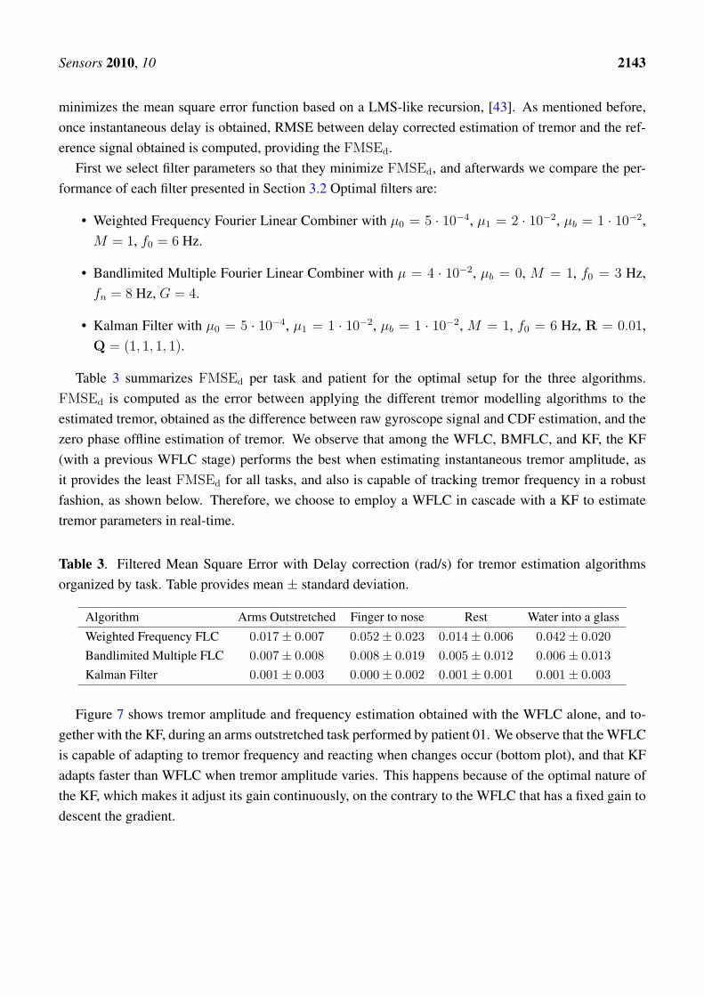
Table 3 summarizes FMSEd per task and patient for the optimal setup for the three algorithms.FMSEd is computed as the error between applying the different tremor modelling algorithms to theestimated tremor, obtained as the difference between raw gyroscope signal and CDF estimation, and thezero phase offline estimation of tremor. We observe that among the WFLC, BMFLC, and KF, the KF(with a previous WFLC stage) performs the best when estimating instantaneous tremor amplitude, asit provides the least FMSEd for all tasks, and also is capable of tracking tremor frequency in a robustfashion, as shown below. Therefore, we choose to employ a WFLC in cascade with a KF to estimatetremor parameters in real-time.
Table 3. Filtered Mean Square Error with Delay correction (rad/s) for tremor estimation algorithmsorganized by task. Table provides mean ± standard deviation.
Algorithm Arms Outstretched Finger to nose Rest Water into a glass
Weighted Frequency FLC 0.017± 0.007 0.052± 0.023 0.014± 0.006 0.042± 0.020
Bandlimited Multiple FLC 0.007± 0.008 0.008± 0.019 0.005± 0.012 0.006± 0.013
Kalman Filter 0.001± 0.003 0.000± 0.002 0.001± 0.001 0.001± 0.003
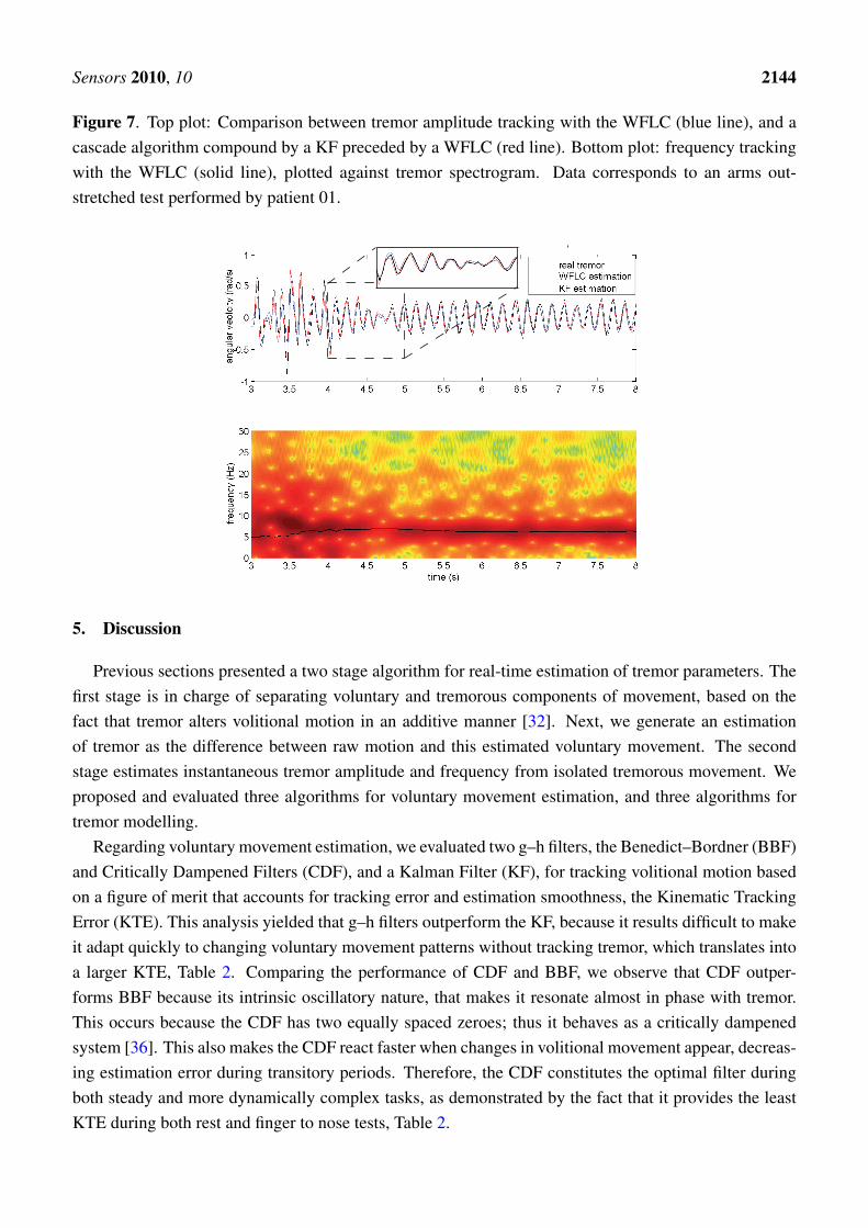
Figure 7 shows tremor amplitude and frequency estimation obtained with the WFLC alone, and to-gether with the KF, during an arms outstretched task performed by patient 01. We observe that the WFLCis capable of adapting to tremor frequency and reacting when changes occur (bottom plot), and that KFadapts faster than WFLC when tremor amplitude varies. This happens because of the optimal nature ofthe KF, which makes it adjust its gain continuously, on the contrary to the WFLC that has a fixed gain todescent the gradient.
Sensors 2010, 10 2144
Figure 7. Top plot: Comparison between tremor amplitude tracking with the WFLC (blue line), and acascade algorithm compound by a KF preceded by a WFLC (red line). Bottom plot: frequency trackingwith the WFLC (solid line), plotted against tremor spectrogram. Data corresponds to an arms out-stretched test performed by patient 01.
5. Discussion
Previous sections presented a two stage algorithm for real-time estimation of tremor parameters. Thefirst stage is in charge of separating voluntary and tremorous components of movement, based on thefact that tremor alters volitional motion in an additive manner [32]. Next, we generate an estimationof tremor as the difference between raw motion and this estimated voluntary movement. The secondstage estimates instantaneous tremor amplitude and frequency from isolated tremorous movement. Weproposed and evaluated three algorithms for voluntary movement estimation, and three algorithms fortremor modelling.
Regarding voluntary movement estimation, we evaluated two g–h filters, the Benedict–Bordner (BBF)and Critically Dampened Filters (CDF), and a Kalman Filter (KF), for tracking volitional motion basedon a figure of merit that accounts for tracking error and estimation smoothness, the Kinematic TrackingError (KTE). This analysis yielded that g–h filters outperform the KF, because it results difficult to makeit adapt quickly to changing voluntary movement patterns without tracking tremor, which translates intoa larger KTE, Table 2. Comparing the performance of CDF and BBF, we observe that CDF outper-forms BBF because its intrinsic oscillatory nature, that makes it resonate almost in phase with tremor.This occurs because the CDF has two equally spaced zeroes; thus it behaves as a critically dampenedsystem [36]. This also makes the CDF react faster when changes in volitional movement appear, decreas-ing estimation error during transitory periods. Therefore, the CDF constitutes the optimal filter duringboth steady and more dynamically complex tasks, as demonstrated by the fact that it provides the leastKTE during both rest and finger to nose tests, Table 2.

Sensors 2010, 10 2145
Figure 8. Block diagram summarizing the two stage algorithm for real-time estimation of instantaneoustremor parameters. First, a Critically Dampened Filter estimates voluntary motion from raw kinematicdata. Next, we generate an estimation of tremor by subtracting voluntary from raw movement. At the sec-ond stage, the Weighted Frequency Fourier Linear Combiner estimates instantaneous tremor frequency,and then feds it into a Kalman Filter that tracks instantaneous tremor amplitude.
8 10 12 14 16 18 20 22−0.4
−0.3
−0.2
−0.1
0
0.1
0.2
0.3
time (s)
agular velocity (rad/s)
Tremor
8 10 12 14 16 18 20 220.05
0.15
0.25
0.35
0.45
time (s)
angular velocity (rad/s)
Total motion
Voluntary motion
A
A
B
B
C
8 10 12 14 16 18 20 22−0.4
−0.3
−0.2
−0.1
0
0.1
0.2
0.3
time (s)
angular velocity (rad/s)
Tremor amplitude
C
D
8 10 12 14 16 18 20 22 0
5
10
15
20
25
30
time (s)
frequency (Hz)
Tremor amplitudeTremor frequency
D
Critically Dampened
FilterKalman Filter
Total motion
Tremor amplitude
Tremor frequency
Voluntary motion
Weighted Frequency
Fourier Linear Combiner
Algorithms for estimation of instantaneous tremor frequency and amplitude are evaluated basedon the Filtered Mean Square Error with Delay correction (FMSEd). This metric presents the advan-tages of accounting for errors due to undershoots and overshoots, and those originated from estimationdelays [42]. First, we evaluated two algorithms originally devoted to physiological tremor tracking, theWeighted Frequency Fourier Linear Combiner (WFLC), and the Bandlimited Multiple Fourier LinearCombiner (BMFLC). Physiological tremor not only has different aetiology than pathological tremors,but also manifests differently in terms of amplitude and frequency [25,26]. Although the WFLC hasalso been successfully employed in the context of pathological tremor estimation [9], we evaluateda novel approach based on a cascade algorithm compound by a WFLC and a Kalman Filter (KF).This algorithm raised as the best solution in the sense it minimizes FMSEd, as it puts together accu-rate tremor frequency estimation based on a WFLC, and an independent KF for amplitude estimation,Table 3. In fact, FMSEd is at least five time smaller than that obtained with the BMFLC, which con-stitutes the second best candidate. KF tremor estimation proves to be robust and precise both duringsteady state regime and transitory periods, while BMFLC and overall WFLC lack of that accurate adap-
Sensors 2010, 10 2146
tation during transients, mainly because of the fixed gain they employ. This is demonstrated becauseperformance in terms of FMSEd degrades the most during finger to nose and water glass tests, Table 3.
Therefore, the optimal architecture for the two-stage algorithm is constituted by a Critically Damp-ened Filter that estimates voluntary movement, and a cascade algorithm compound by a Weighted Fre-quency Fourier Linear Combiner that estimates tremor frequency and feds it into a Kalman Filter thattracks tremor amplitude, Figure 8. This approach provides an average tremor estimationerror 0.001± 0.002 rad/s, with robust frequency tracking if compared to spectrograms.
6. Conclusions
This paper presented a two stage algorithm for real-time estimation of instantaneous tremor parame-ters. At the first stage, the algorithm separates tremorous and concomitant voluntary movement based ontheir different distributions in the frequency domain. Next, estimated voluntary movement is removedfrom raw kinematic data, in order to generate an estimation of tremor. This estimation is then fed, at asecond stage, into a Weighted Frequency Fourier Linear Combiner (WFLC) that tracks tremor frequency,and into a Kalman Filter that uses WFLC frequency information to estimate tremor amplitude.
The resulting algorithm provides accurate estimation of tremor amplitude, with an average FMSEd of0.001± 0.002 rad/s, and robust frequency estimation when compared with spectrograms. Our two stagealgorithm has been validated with patients suffering from major pathologies that cause tremor during theexecution of both clinical and functional tasks. Real-time tremor parameters will be employed to drive a“soft robot” or neuroprosthesis for tremor suppression based on Functional Electrical Stimulation.
Acknowledgements
The work presented in this paper has been carried out with the financial support from the Commissionof the European Union, within Framework 7, specific IST programme “Accessible and Inclusive ICT”,Target outcome 7.2 “Advanced self-adaptive ICT-enabled assistive systems based on non-invasive Brainto Computer Interaction (BCI)”, under Grant Agreement number ICT-2007-224051, “TREMOR: Anambulatory BCI-driven tremor suppression system based on functional electrical stimulation.”
References
1. Deuschl, G.; Raethjen, J.; Lindemann, M.; Krack, P. The pathophysiology of tremor. Muscle Ner.2001, 24, 716–735.
2. Rocon, E.; Belda-Lois, J.M.; Sanchez-Lacuesta, J.M.; Pons, J.L. Pathological tremor management:Modelling, compensatory technology and evaluation. Technol. Disabil. 2004, 16, 3–18.
3. Deuschl, G.; Bain, P.; Brin, M. Consensus statement of the movement disorder society on tremor.Ad hoc scientific committee. Mov. Disord. 1998, 13, 2–23.
4. Ushe, M.; Mink, J.W.; Revilla, F.J.; Wernle, A.; Gibson, P.S.; McGee-Minnich, L.; Hong, M.;Rich, K.M.; Lyons, K.E.; Pahwa, R.; Perlmutter, J.S. Effect of stimulation frequency on tremorsuppression in essential tremor. Mov. Disord. 2004, 19, 1163–1168.
Sensors 2010, 10 2147
5. Burkhard, P.R.; Vingerhoets, F.J.G.; Berney, A.; Bogousslavsky, J.; Villemure, J.G.;Ghika, J. Suicide after successful deep brain stimulation for movement disorders. Neurology2004, 63, 2170–2172.
6. Stiles, R.N.; Randall, J.E. Mechanical factors in human tremor frequency. J. Appl. Physiol. 1967,23, 324–330.
7. Joyce, G.C.; Rack, P.M.H. The effects of load and force on tremor at the normal human elbow joint.J. Physiol. 1974, 240, 375–396.
8. Adelstein, B.D. Peripheral Mechanical Loading and the Mechanism of Abnormal Intention Tremor;Master’s Thesis; Massachusetts Institute of Technology: Cambridge, MA, USA, 1981.
9. Rocon, E.; Belda-Lois, J.M.; Ruiz, A.F.; Manto, M.; Moreno, J.C.; Pons, J.L. Design and Validationof a Rehabilitation Robotic Exoskeleton for Tremor Assessment and Suppression. IEEE Trans.Neural Syst. Rehab. Eng. 2007, 15, 367–378.
10. Popovic, D.; Sinkjaer, T. Control of Movement for the Physically Disabled; Springer: New York,NY, USA, 2000.
11. Popovic, D.; Stojanovic, A.; Pjanovic, A.; Radosavljevic, S.; Popovic, M.; Jovic, S.; Vulovic, D.Clinical evaluation of the bionic glove. Arch. Phys. Med. Rehabil. 1999, 80, 299–304.
12. Mayagoitia, R.E.; Nene, A.V.; Veltink, P.H. Accelerometer and rate gyroscope measurement ofkinematics: an inexpensive alternative to optical motion analysis systems. J. Biomech. 2002,35, 537–542.
13. Pons, J.L., Ed. Wearable Robots: Biomechatronic Exoskeletons; John Wiley & Sons: Hoboken,NJ, USA, 2008.
14. Vinjamuri, R.; Crammond, D.J.; Kondziolka, D.; Lee, H.N.; Mao, Z.H. Extraction of sourcesof tremor in hand movements of patients with movement disorders. IEEE Trans. Inform. Tech.Biomed. 2009, 13, 49–56.
15. Elble, R.J.; Sinha, R.; Higgins, C. Quantification of tremor with a digitizing tablet. J. Neurosci.Meth. 1990, 32, 193–98.
16. Riviere, C.N.; Rader, R.S.; Thakor, N.V. Adaptive canceling of physiological tremor for improvedprecision in microsurgery. IEEE Trans. Biomed. Eng. 1998, 45, 839–846.
17. Veluvolu, K.C.; Tan, U.X.; Latt, W.T.; Shee, C.Y.; Ang, W.T. Bandlimited Multiple Fourier LinearCombiner for real-time tremor compensation. In Proceedings of International Conference of theIEEE Engineering in Medicine and Biology Society, Kiel, Germany, August 27–31, 2007.
18. Elble, R.J.; Koller, W.C. Tremor; The John Hopkins Univesity Press: Baltimore, MD, USA, 1990.19. Grimaldi, G.; Manto, M. Tremor from Pathogenesis to Treatment; Morgan & Claypool: San Rafael,
CA, USA, 2008.20. Rocon, E.; Moreno, J.C.; Ruiz, A.F.; Brunetti, F.; Miranda, J.A.; Pons, J.L. Application of iner-
tial sensors in rehabilitation robotics. In Proceedings of IEEE 10th International Conference onRehabilitation Robotics, Noordwijk, The Netherlands, June 12–15, 2007; pp. 145–150.
21. Luinge, H.J.; Veltink, P.H. Measuring orientation of human body segments using miniature gyro-scopes and accelerometers. Med. Biol. Eng. Comput. 2005, 43, 273–282.
Sensors 2010, 10 2148
22. Roetenberg, D.; Luinge, H.J.; Baten, C.T.M.; Veltink, P.H. Compensation of magnetic disturbancesimproves inertial and magnetic sensing of human body segment orientation. IEEE Trans. NeuralSyst. Rehab. Eng. 2005, 13, 395–405.
23. Harada, T.; Uchino, H.; Mori, T.; Sato, T. Portable orientation estimation device based on ac-celerometers, magnetometers and gyroscope sensors for sensor network. In Proceedings of IEEEInternational Conference on MFI2003 Multisensor Fusion and Integration for Intelligent Systems,Tokyo, Japan, July 30–August 1, 2003; pp. 191–196.
24. Rocon, E.; Andrade, A.O.; Pons, J.L.; Kyberd, P.; Nasuto, S.J. Empirical Mode Decomposition: anovel technique for the study of tremor time series. Med. Biol. Eng. Comput. 2006, 44, 569–582.
25. Elble, R. Tremor: clinical features, pathophysiology, and treatment. Neurologic. Clin. 2009,27, 679–695.
26. Veluvolu, K.C.; Latt, W.T.; Ang, W.T. Double adaptive bandlimited multiple Fourier linear com-biner for real-time estimation/filtering of physiological tremor. Biomed. Signal Process. Control2010, 5, 37–44.
27. Bo, A.P.L.; Poignet, P.; Geny, C. Filtering voluntary motion for pathological tremor compensation.In Proceedings of International Conference on Intelligent Robots and Systems, St. Louis, MO, USA,October 11–15, 2009.
28. Kotovsky, J.; Rosen, M.J. A wearable tremor-suppression orthosis. J. Rehabil. Res. Dev. 1998,35, 373–387.
29. Tong, K.; Granat, M.H. A practical gait analysis system using gyroscopes. Med. Eng. Phys. 1999,21, 87–94.
30. Fahn, S.; Tolosa, E.; Marin, C. Clinical rating scale for tremor. In Parkinson’s Disease and Move-ment Disorders; Urban & Schwarzenberg: Wien, Austria, 1998; pp. 225–234.
31. Belda-Lois, J.M.; Rocon, E.; Sanchez-Lacuesta, J.J.; Ruiz, A.F.; Pons, J.L. Functional assessmentof tremor in the upper limb. In Proceedings of European Conference for the Advancement ofAssistive Technology in Europe, Lille, France, September 6–9, 2005.
32. Riley, P.O.; Rosen, M.J. Evaluating manual control devices for those with tremor disability. J.Rehabil. Rese. Dev. 1987, 24, 99–110.
33. Riviere, C.N. Adaptive Suppression of Tremor for Improved Human Machine Control; PhD Thesis;John Hopkins University: Baltimore, MD, USA, 1981.
34. Mann, K.A.; Werner, F.W.; Palmer, A.K. Frequency spectrum analysis of wrist motion for activitiesof daily living. J. Orthop. Res. 1989, 7, 304–306.
35. Widrow, B.; Glover, J.R.; McCool, J.M.; Kaunitz, J.; Williams, C.S.; Hearn, R.H.; Zeidler, J.R.;Dong, E.; Goodlin, R.C. Adaptive noise canceling: Principles and applications. Proc. IEEE 1975,63, 1692–1716.
36. Brookner, E. Tracking and Kalman Filtering Made Easy; John Wiley & Sons: Hoboken, NJ, USA,1998.
37. Benedict, T.R.; Bordner, G.W. Synthesis of an optimal track-while-scan smoothing equations. IRETrans. Automat. Control 1962, 7, 27–32.
38. Bar-Shalom, Y.; Li, X.R. Estimation and Tracking: Principles, Techniques and Software; ArtechHouse Publishers: Norwood, MA, USA, 1998.
Sensors 2010, 10 2149
39. O’Suilleabhain, P.E.; Matsumoto, J.Y. Time-frequency analysis of tremors. Brain 1998, 121,2127–2134.
40. Vaz, C.; Kong, X.; Thakor, N. An adaptive estimation of periodic signals using a Fourier linearcombiner. IEEE Trans. Signal Process. 1994, 42, 1–10.
41. Rocon, E. Reduccion Activa de Temblor Patologico de Miembro Superior Mediante ExoesqueletosRoboticos; PhD Thesis; Universidad Politecnica de Madrid: Madrid, Spain, 2006.
42. Gonzalez, J.G.; Heredia, E.A.; Rahman, T.; Barner, K.E.; Arce, G.R. Optimal digital filtering fortremor suppression. IEEE Trans. Biomed. Eng. 2000, 47, 664–673.
43. Etter, D.; Stearns, S. Adaptive estimation of time delays in sampled data systems. IEEE Trans.Acoust. Speech Signal Process. 1981, 29, 582–587.
© 2010 by the authors; licensee Molecular Diversity Preservation International, Basel, Switzerland. Thisarticle is an open-access article distributed under the terms and conditions of the Creative CommonsAttribution license http://creativecommons.org/licenses/by/3.0/.