Real Time Controller Functional Requirements Don Gavel & Marc Reinig UCO Lick, laboratory for...
35
Real Time Controller Functional Requirements Don Gavel & Marc Reinig UCO Lick, laboratory for Adaptive Optics. Keck NGAO Team Meeting December 13, 2007 Videoconference
-
date post
21-Dec-2015 -
Category
Documents
-
view
218 -
download
3
Transcript of Real Time Controller Functional Requirements Don Gavel & Marc Reinig UCO Lick, laboratory for...
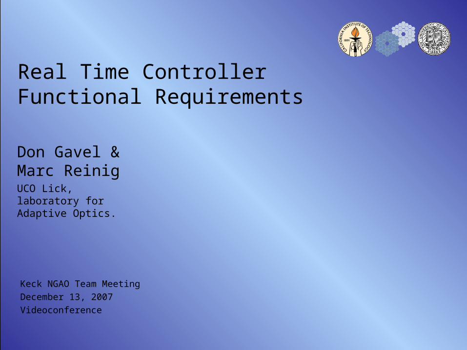
Real Time Controller Functional Requirements
Don Gavel & Marc ReinigUCO Lick, laboratory for Adaptive Optics.
Keck NGAO Team Meeting
December 13, 2007
Videoconference

NGAO Real Time Controller FRD 2
Outline
• Status• Issues• Plans

NGAO Real Time Controller FRD 3
Status
• We have an architecture that meets the performance requirements– 9 LGS/WFS (64x64)
– 2 Tip/Tilt WFS
– 1 T/T-focus-astigmatism WFS
– 1 Truth WFS
– 5 DM’s (with T/T) (64x64)
– 1 Woofer
– <500µSec from receipt of image to commands received at the DM
• Scalable to larger problems• We have validated the software in the lab and through simulation
NGAO Real Time Controller FRD 4
Architecture – Hardware and Software –

NGAO Real Time Controller FRD 5
NGAO System Context Block Diagram(DRAFT)
Observing Sequencer
DataServer
Atmospheric Tools
Telescope Interface
Instrument Sequencer
LTCSLaser
Sequencer
LaserLaunchFacility
AOSequencer
RTCLO WFSControl
TWFSControl
Acquisition Control
NGSHOWFSControl
9 LGSHOWFSControl
RelayDM/TTControl
NGSWFS
LGS WFS
x9
AcqCam
LO WFS
x3
DM/TT
TWFS
PixelData
PixelData
MotionControl
SensorControl
PixelData
MotionControl
SensorControl
MotionControl
PixelData
MotionControl
DeviceControl
PixelData
MotionControl
CorrectorCommands
MotionControl
SensorControl
DeviceControl
SensorControl
Status
Cmd
Telem
StatusStatusCmdCmdTelemTelem
dNIRIOpto-Mech
Control
MEMs
DMsx6
MotionControl
DeviceControl
CorrectorCommands
Optics BenchControl
Optics
Bench
Devs
MotionControl
DeviceControl
RT Diags
RT Diags RT Diags
Off-load
LaserLaser Safety System
Bore-sightCam
LaserServi
ceEncl
Spotter
Status
Telem
Cmd
Status
TelStatus
Status
Status
E-Stop
UplinkTT
LaserOpto-Mech
DeviceControl
MotionControl
Diag
ConfigData
Status Status
LFOpto-Mech
DeviceControl
MotionControl
Diag
TelemLaserTelem
Version 5, 10/31/07Erik Johansson
Legend: Non-Real-Time Commands and Data
Real-Time Commands and Data
Real-Time Diagnostic Data
LO WFSDMsx3
CorrectorCommands
PixelData
PSFMonitoringCameras
PSFCams
X?
MotionControl
DeviceControl
PixelData

NGAO Real Time Controller FRD 6
NGAO System Context Block Diagram(DRAFT) cont.
Observing Sequencer
DataServer
Atmospheric Tools
Telescope Interface
Instrument Sequencer
LTCSLaser
Sequencer
LaserLaunchFacility
AOSequencer
RTCLO WFSControl
TWFSControl
Acquisition Control
NGSHOWFSControl
9 LGSHOWFSControl
RelayDM/TTControl
NGSWFS
LGS WFS
x9
AcqCam
LO WFS
x3
DM/TT
TWFS
PixelData
PixelData
MotionControl
SensorControl
PixelData
MotionControl
SensorControl
MotionControl
PixelData
MotionControl
DeviceControl
PixelData
MotionControl
CorrectorCommands
MotionControl
SensorControl
DeviceControl
SensorControl
Status
Cmd
Telem
StatusStatusCmdCmdTelemTelem
dNIRIOpto-Mech
Control
MEMs
DMsx6
MotionControl
DeviceControl
CorrectorCommands
Optics BenchControl
Optics
Bench
Devs
MotionControl
DeviceControl
RT Diags
RT Diags RT Diags
Off-load
LaserLaser Safety System
Bore-sightCam
LaserServi
ceEncl
Spotter
Status
Telem
Cmd
Status
TelStatus
Status
Status
E-Stop
UplinkTT
LaserOpto-Mech
DeviceControl
MotionControl
Diag
ConfigData
Status Status
LFOpto-Mech
DeviceControl
MotionControl
Diag
TelemLaserTelem
Version 5, 10/31/07Erik Johansson
Legend: Non-Real-Time Commands and Data
Real-Time Commands and Data
Real-Time Diagnostic Data
LO WFSDMsx3
CorrectorCommands
PixelData
PSFMonitoringCameras
PSFCams
X?
MotionControl
DeviceControl
PixelData

NGAO Real Time Controller FRD 7
Interface to SRT System
• SRT controls all aspects of RTC - Ethernet– There will be a non-RT Linux PC controlling the RTC
– Interface to the SRT will be Ethernet between the SRT and the RTC control PC
– Load and read the RTC code for all operations
– Load and read the RTC HW configuration
• Telemetry streams to monitoring, PSF, etc - Ethernet• Interface between the RTC and the high-speed disk arrays for
diagnostic data - Fiber Link or equivalent

NGAO Real Time Controller FRD 8
NGAO RTC System Context Block Diagram(DRAFT)
Observing Sequencer
DataServer
Telescope InterfaceAO
Sequencer
RTCLO WFSControl
TWFSControl
NGSHOWFSControl
9 LGSHOWFSControl
NGSWFS
LGS WFS x9
LO WFSx3
DM/TT TWFS
PixelDataPixel
Data
MotionControl
SensorControl
PixelData
MotionControl
SensorControl
MotionControl
DeviceControl
PixelData
CorrectorCommands
MotionControl
SensorControl
Status
Cmd
Telem
Status
Cmd
Telem
MEMsDMsx6
CorrectorCommands
RT Diags
RT Diags
Off-load
UplinkTT
ConfigData
LFOpto-Mech
Telem
Version 2, Nov 11, 2007Marc Reinig
Legend:Non-Real-Time Commands and Data
Real-Time Commands and Data
Real-Time Diagnostic Data
LO WFSDMsx3
CorrectorCommands
PixelData
High Speed DataServer
High Speed Diagnostic Data

NGAO Real Time Controller FRD 9
Tomography Is Part of a Larger System – With characteristics that lend themselves to a similar solution –
ImageProcessors
ImageProcessors
ImageProcessors
ImageProcessors
WavefrontSensorsWavefrontSensorsWavefrontSensorsWavefrontSensors
TomographyUnit
ImageProcessors
ImageProcessors
ImageProcessors
DMFit
WavefrontSensorsWavefrontSensorsWavefrontSensors
DMProjection
DM conjugatealtitude
Cn2 profile Actuatorinfluencefunction
Centroid algorithmr0, guidstar brightness,
Guidestar position
ImageProcessors
ImageProcessors
ImageProcessorsDeformable
Mirrors
ImageProcessors
ImageProcessors
ImageProcessors
ImageProcessors
WavefrontSensorsWavefrontSensorsWavefrontSensorsWavefrontSensors
TomographyUnit
ImageProcessors
ImageProcessors
ImageProcessors
DMFit
WavefrontSensorsWavefrontSensorsWavefrontSensors
DMProjection
DM conjugatealtitude
Cn2 profile Actuatorinfluencefunction
Centroid algorithmr0, guidstar brightness,
Guidestar position
ImageProcessors
ImageProcessors
ImageProcessorsDeformable
Mirrors
Guide star height
Kolmogorov filterLayer heights
Independent parallel streams of parallelizable
processesMore independent parallel
streams!
Back-propagate
Post-condition
Forward-propagate
FT FT-1X
Aperture
WFSdata
VolumetricOPD
estimates-+
Pre-condition
FT-1 FTX
Aperture
Back-propagate
Post-condition
Forward-propagate
FT FT-1X
Aperture
WFSdata
VolumetricOPD
estimates-+
Pre-condition
FT-1 FTX
Aperture

NGAO Real Time Controller FRD 10
A Systolic Array

NGAO Real Time Controller FRD 11
Data Rate and Location
WFSCam
Hartmann sensor optics
...
Localframegrab
analog cable length constraints
Localdedicatedcentroider
TomographyEngine
Wooferfits
TweeterfitsHigh
VoltageD/A
converter
TweeterDeformable
Mirror
digital cable (prefer DMA transfer)
HighVoltage
D/Aconverter
WooferDeformable
Mirror
...
HV cable length constraints
NasmythNasmyth
Nasmyth
Computer Room
Fiber Link or equivalent
(>160MB/Sec each)
Telemetry Data
Diagnostic Data(To Disk) (>1 GB/Sec)

NGAO Real Time Controller FRD 12
Telemetry and Diagnostics Streams
Telemetry (Low bandwidth, on-line monitoring) (>1Hz)• Set and read the telemetry rate for each data stream• Set and read the data streams that are enabled for telemetry
– Centroids– Residual tomography error– DM commands, including uplink– Tip/Tilt commands
Diagnostics (High bandwidth, stored to disk) (full frame rate) (Could be > 1GB/Sec)
• Set and read the diagnostic rate for each data stream• Set and read the data streams that are enabled for diagnostics
– Centroids– Residual tomography error– Raw layer information– DM commands, including uplink– Collapsed layer information– Tip/Tilt commands

NGAO Real Time Controller FRD 13
RTC Software Flow
ATM
Woofer
Woofergo-toerror
WooferWoofer
Fit
FitTweeter
Tweeter
...
Average
CollapseTomography
...
-
+
+
+
+
+
+
-
Tweeter
ATM
Woofer
Woofergo-toerror
WooferWoofer
Fit
FitTweeter
Tweeter
...
Average
CollapseTomography
...
-
+
+
+
+
+
+
-
Tweeter

NGAO Real Time Controller FRD 14
Tomography Basic Loop
Forward Propagate
Back Propagate
Calculate New
Estimate
Error > Limit
Error <= Limit
Done
Start
Measured Value From WFS
Calculate Error
Error Limit
Forward Prop(G)
IDFT(FP)
measure error
Dynamic data Static Data
current estimated values for voxels passed through layers
multiplied by shift(layer,guide star)
IDFT coefficients
forward propagated values passed by rows (east/west) then columns (north/south)
apply aperture 1 or 0 depending on locationSpatial fwd prop value
Measured valueSpatial adj fwd prop value
DFT(error)error values passed by rows (east/west) then columns (north/south)
DFT coefficients
Back propagation CN2 value(Layer)Accumulate error values for each guide star in each voxel in each layer
Kolmogorov Filter K_filter valueCoeff error
Guide Star = 1(G = 1)
G = G + 1
no
yes
New Estimate Error Old estimate
Fourier Domain
Spatial Domain
Store Error(G)
An error magnitude for this guide star:|E| = (real)2 + (imag)2 is summed across all columns and rows. This value is stored for global error.
Global ErrorSum the Sum of Squares error values across all guide stars
Error < Cutoff?
yes
no
Done
G = 1
G == Total #Guide Stars?
yes
no
G = G + 1
G == Total #Guide Stars?
Sum of Squares and Store(G)
The error vectors for this guide star are stored for back propagation

NGAO Real Time Controller FRD 15
Forward Propagation
New Voxel Estimate, Layer(0)
Adjust for Shift for Layer(0)
New Voxel Estimate, Layer(N)
Adjust for Shift for Layer(N)
Sum All Adjusted
Values in the Ray Path
Calculate Error Guide
Star (N)
Measured Value From WFS(0)
Forward PropagateBack Propagate
Calculate New Estimate
Error > Limit
Error <= Limit
Done
Start
Measured Value From WFS
Calculate Error
Error Limit
For each sub aperture, sum all the estimated Voxel values, along the path of a ray to each Guide Star.
In the Fourier domain, you must account for the spatial shift that occurs in the spatial domain. This will be the complex conjugate of the shift value used in the back propagation.

NGAO Real Time Controller FRD 16
Calculate Error
Subtract Forward
Propagated Value from
Measured Value for each WFS
Forward Propagate
Measured Value From
WFS(0)
Back Propagate
Error > Limit
Error <= Limit
Done
Compare Error to
Limit
Error Limit
Forward PropagateBack Propagate
Calculate New Estimate
Error > Limit
Error <= Limit
Done
Start
Measured Value From WFS
Calculate Error
Error Limit
For each sub aperture, for each ray from a Guide Star, calculate the error between the forward propagated value and the measured value from the WFS for that Guide Star.
If you have reached the limit stop, else continue with another loop

NGAO Real Time Controller FRD 17
Back PropagateCalculate
New Estimate for this Voxel
Adjust Error(N) For Gain and Cn
2 (Multiply)
Adjust Error(N) for
Shift (Multiply)
Measured Value From WFS(N)
Calculate Error Guide
Star (N)
Adjust Error(0) For Gain and Cn
2 (Multiply)
Adjust Error(0) for
Shift for this Layer
(Multiply)
Measured Value From WFS(0)
Calculate Error Guide
Star (0) Forward Propagate Guide Star
(N)Forward
Propagate Guide Star
(0)
Error Limit
Forward PropagateBack Propagate
Calculate New Estimate
Error > Limit
Error <= Limit
Done
Start
Measured Value From WFS
Calculate Error
Error Limit
For each guide star, for each sub aperture, back propagate the error for a guide star to all the Voxels along the ray back to the Guide Star (These should be the same Voxels used in calculating the Forward Propagated value.)
Adjust the error for each Voxel for the Cn2
value for its layer
In the Fourier domain, you must account for the spatial shift that occurs in the spatial domain. This will be the complex conjugate of the shift value used in the Forward propagation.

NGAO Real Time Controller FRD 18
Calculate New Estimate
Forward Propagate
GS(0)
Back Propagate
d GS Error(N)
Back Propagate
d GS Error(0)
Average Adjusted
Errors
Add to Current
Estimated Value
Forward PropagateBack Propagate
Calculate New Estimate
Error > Limit
Error <= Limit
Done
Start
Measured Value From WFS
Calculate Error
Error Limit
Forward Propagate
GS(N)
For each Voxel, calculate the average of the adjusted errors that were back propagated along the rays to various Guide Stars and add this to the estimated value for the Voxel to get a new estimated value.

NGAO Real Time Controller FRD 19
WFS Control CommandsCamera• Set and read the camera frame rate• Set and read the camera pixel rate• Set and read the camera gainCentroiding• Load the dark pattern• Load pixel gain pattern• Set and read the threshold level• Set and read the centroiding algorithm• Load and read the centroid weights• Load and read the reference centroids• Load and read the centroid offsets• Set and read pixel offsets for the camera image• Set and read the guidestar mode (NGS or LGS) for any WFS• Load and read centroid non linearity tables

NGAO Real Time Controller FRD 20
Tomography Control Commands
• Load and read the cone-effect scaling array for any guide star or target
• Load and read the sky position for any guidestar or target• Load and read the Kolmogorov filter array• Load and read the pre-conditioning arrays• Load and read the tomography loop gain arrays• Load and read the tomography bailout value
• Load and read the Cn2 values for all layers
• Load and read the wind array for all layers

NGAO Real Time Controller FRD 21
DM and Tip/Tilt Control Commands
• Load and read the layer-to-DM collapse arrays• Load and read the DM command matrixes and non linearity lookup
tables for open and closed loop control• Set and read DM open/closed loop mode• Set and read the Tip/Tilt command matrixes

NGAO Real Time Controller FRD 22
Calibration Capabilities
• Create a system matrix for any DM• Set the number of frames to use when creating the system matrix• Clear the DM of any manually set values• Calibrate science target DMs in MOAO• Woofer• Tweeter• Force an arbitrary camera image for any WFS• Force an arbitrary centroid output for any tomography WFS input• Force an arbitrary layer pattern to be used by the DM command
module• Send an arbitrary pattern to any DM• Save the current centroid positions as an reference centroid file
(averaged over a settable number of frames)

NGAO Real Time Controller FRD 23
System Diagnostics Capabilities
• Read all chip temperatures• Read system temperatures at various predetermined locations• Monitor chip and system fan operation• Set and read temperature alarm trip levels

NGAO Real Time Controller FRD 24
Reliability and Reparability
• Graceful degradation• Spares requirement• MTBF• Self Healing (SEU)

NGAO Real Time Controller FRD 25
Physical Characteristics
• Size– <20 m3
• Weight – TBD
• Location– WFS and DM Drive are on the Nasmyth
– RTC and High Speed Disk array are in the computer room
• Power– <20KW

NGAO Real Time Controller FRD 26
Issues Remaining
• Determine Single Event Upset (SEU) rate from Gamma/Cosmic rays
• Verify detection and recovery scheme

NGAO Real Time Controller FRD 27
Plans
• Complete FRD• Finish writing report• Validate SEU issues

NGAO Real Time Controller FRD 28
Backups

NGAO Real Time Controller FRD 29
Data Rate Work SheetMCAO MOAO
Radial Voxels
Sub apertures across primary 64 64 64Sub aperature at altitued 3 3 3Number of WFSs 10 10 10Number of Pixels per WFS Camera 32,000 32,000 32,000Camera transfer time to WFS (µSec) 400 400 400Number of Layers 7 7 7Number of MCAO DM's 2 2 2Number of observing DMs (only relevant for MOAO) 6 5 5Word size (Bytes) 2 2 2Portion of a frame used for transfer time (% frame) (Transfers of WFS data-in and DM data-out are overlapped) 10% 10% 10%Frame time (µSec) 500 500 500Input and output control data rates (MB/Sec)
Per Camera 160 160 160Total Camera 1,600 1,600 1,600Per WFS 164 164 164Total WFS 1,638 1,638 1,638Per DM 164 164 164Total DM 328 983 983
Diagnostic data rates (MB/Sec)Per Camera 128 128 128Total Camera 1,280 1,280 1,280Per WFS 16 16 16Total WFS 164 164 164Per Layer 1,475 1,475 164Total Layer 10,322 10,322 1,147Per DM 16 16 16Total DM 33 98 98
Diagnostic Storage Rate w/o layer info (GB/Sec) 1.5 1.5 1.5Maximum diagnostic Storage Rate (GB/Sec) 12 12 3Giga Bytes of Mass Storage per minute 708 712 161

NGAO Real Time Controller FRD 30
Sample Code to Configure the Hardware– Simple ALU –
module alu4 ( input_a, input_b, output_c, ctrl_0, ctrl_1, ctrl_2,ctrl_3, clr, clk ); input ctrl_0, ctrl_1, ctrl_2, ctrl_3; input [15:0] input_a, input_b; output [31:0] output_c; input clr, clk;
wire [3:0] ctrl; reg [31:0] output_c;
assign ctrl = {ctrl_3, ctrl_2, ctrl_1, ctrl_0}; parameter ADD = 4'b1001; parameter MUL = 4'b0001; parameter NOP = 4'b1000;
always @(posedge clk or posedge clr) begin if (clr) output_c <= 0; else case (ctrl) ADD: output_c <= input_a + input_b; MUL: output_c <= input_a * input_b; default:; endcase endendmodule
NGAO Real Time Controller FRD 31
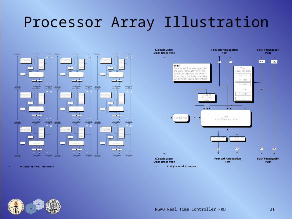
Processor Array Illustration
VoxelLocal Registers
Control Logic
GS1 Error
Current Estimated
ValueCn
2
GSN Error
GS3 Error
GS2 Error
ALU(Word Size + NGS) wide
GSn
...
...
GS1
GS1 ...
...
Cumulative Value GS1
Cumulative Value
GSn
GSn
Forward Propagation Path
Forward Propagation Path
Back PropagationPath
Back PropagationPath
GS1
GS1 ...Note:Because the Forward propagation and Back Progagation paths are parallel, but are used at different times, they will actually be a single bus in the physical implementation .
Global SystemState Information
Global SystemState Information
GSn
GSn
VoxelLocal Registers
Control Logic
GS1 Error
Current Estimated
ValueCn
2
GSN Error
GS3 Error
GS2 Error
ALU(Word Size + NGS) wide
GSn
...
...
GS1
GS1 ...
...
Cumulative Value GS1
Cumulative Value
GSn
GSn
Forward Propagation Path
Forward Propagation Path
Back PropagationPath
Back PropagationPath
GS1
GS1 ...Note:Because the Forward propagation and Back Progagation paths are parallel, but are used at different times, they will actually be a single bus in the physical implementation.
Global SystemState Information
Global SystemState Information
GSn
GSn
• A Single Voxel Processor• An Array of Voxel Processors
NGAO Real Time Controller FRD 32
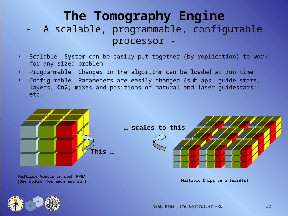
The Tomography Engine- A scalable, programmable, configurable processor -
• Scalable: System can be easily put together (by replication) to work for any sized problem
• Programmable: Changes in the algorithm can be loaded at run time
• Configurable: Parameters are easily changed (sub aps, guide stars, layers, Cn2; mixes and positions of natural and laser guidestars; etc.
Multiple Voxels in each FPGA(One column for each sub ap.) Multiple Chips on a Board(s)
This …
… scales to this

NGAO Real Time Controller FRD 33
A Single FPGA Can Hold Hundreds of Voxels
A Circuit Board Can Hold A Dozen FPGA’s

NGAO Real Time Controller FRD 34
Basing Our Architecture onOur Knowledge of Structure
And use that model for our structure for the iterative solution
We divide the atmosphere into regions called “voxels”

NGAO Real Time Controller FRD 35
Using Our Knowledge of Structure
Each column of voxels is a complete sub aperture containing all layers in our model of the atmosphere.Multiple sub apertures are arrayed in each FPGA chip
Multiple Chips on a Board, and multiple boards to satisfy the size of the problem
This …
… scales to this
VoxelLocal Registers
Control Logic
GS1 Error
Current Estimated
ValueCn
2
GSN Error
GS3 Error
GS2 Error
ALU(Word Size + NGS) wide
GSn
...
...
GS1
GS1 ...
...
Cumulative Value GS1
Cumulative Value
GSn
GSn
Forward Propagation Path
Forward Propagation Path
Back PropagationPath
Back PropagationPath
GS1
GS1 ...Note:Because the Forward propagation and Back Progagation paths are parallel, but are used at different times, they will actually be a single bus in the physical implementation.
Global SystemState Information
Global SystemState Information
GSn
GSn
We give each voxel its own simple processor
These Voxel processors are interconnected, modeled after the
structure of our problem
• For a single Voxel
• Examining the problem, we find:
• All calculations for all voxels are identical
• Most operations on voxels are independent of other voxels
• Operations are simple
• Memory requirements are modest
• This is an “Embarrassingly” parallel problem
• So …