Real-time C Code Generation in Ptolemy II for the Giotto...
40
Real-time C Code Generation in Ptolemy II for the Giotto Model of Computation Shanna-Shaye Forbes Electrical Engineering and Computer Sciences University of California at Berkeley Technical Report No. UCB/EECS-2009-76 http://www.eecs.berkeley.edu/Pubs/TechRpts/2009/EECS-2009-76.html May 20, 2009
Transcript of Real-time C Code Generation in Ptolemy II for the Giotto...

Real-time C Code Generation in Ptolemy II for theGiotto Model of Computation
Shanna-Shaye Forbes
Electrical Engineering and Computer SciencesUniversity of California at Berkeley
Technical Report No. UCB/EECS-2009-76
http://www.eecs.berkeley.edu/Pubs/TechRpts/2009/EECS-2009-76.html
May 20, 2009

Copyright 2009, by the author(s).All rights reserved.
Permission to make digital or hard copies of all or part of this work forpersonal or classroom use is granted without fee provided that copies arenot made or distributed for profit or commercial advantage and that copiesbear this notice and the full citation on the first page. To copy otherwise, torepublish, to post on servers or to redistribute to lists, requires prior specificpermission.
Acknowledgement
This work was supported in part by the Center for Hybrid and EmbeddedSoftware Systems (CHESS) at UC Berkeley, which receives support fromthe National Science Foundation (NSF awards #0720882 (CSR-EHS:PRET) and #0720841 (CSR-CPS)), the U. S. Army Research Office (ARO#W911NF-07-2-0019), the U. S. Air Force Office of Scientific Research(MURI #FA9550-06-0312), the Air Force Research Lab (AFRL), the Stateof California Micro Program, and the following companies: Agilent, Bosch,Lockheed-Martin, National Instruments, and Toyota. It was also supportedin part by the NASA Harriet G. Jenkins Pre-doctoral Fellowship Program(JPFP).

Real-time C Code Generation in Ptolemy II for the Giotto Model of
Computation
by Shanna-Shaye Forbes
Research Project
Submitted to the Department of Electrical Engineering and Computer Sciences, University of Cal-
ifornia at Berkeley, in partial satisfaction of the requirements for the degree of Master of Science,
Plan II.
Approval for the Report and Comprehensive Examination:
Committee:
Edward A. Lee
Research Advisor
Date
* * * * * *
Sanjit Seshia
Second Reader
Date

Abstract
Giotto is a programming model for embedded control systems that is applicable to hard real-
time specifications that are periodic and feature multi-modal behavior. Examples of such systems
include fly-by-wire or brake-by-wire systems where sensor readings must be periodic and there are
multiple modes of operation.
Ptolemy II is a university based open source modeling and simulation framework that supports
model-based design, and facilitates actor oriented and objected oriented programming. It serves
as a laboratory for the modeling and simulation necessary in the design of a real-time embedded
system. Ptolemy also has a C code generation framework that generates code for different targets.
Ptolemy II has an implementation of the Giotto programming model, that allows the simu-
lation of Giotto models in Ptolemy II. In this report we discuss our ability to implement Giotto
semantics using code generation and a real-time operating system. We illustrate these techniques
with Ptolemy II and the FreeRTOS embedded operating system. To illustrate these techniques we
extend the code generation framework within Ptolemy II to generate C code for the Giotto pro-
gramming model. We have implemented a C code generation adapter in Ptolemy II for the Giotto
model of computation targeted to systems capable of running the FreeRTOS operating system. We
present an elevator controller as an example that uses the code generation framework.
2

Contents
1 Introduction 8
2 Background 11
2.1 Giotto . . . . . . . . . . . . . . . . . . . . . . . . . . . . . . . . . . . . . . . . . 11
2.1.1 Related Work . . . . . . . . . . . . . . . . . . . . . . . . . . . . . . . . . 14
2.2 Ptolemy II . . . . . . . . . . . . . . . . . . . . . . . . . . . . . . . . . . . . . . . 15
2.3 Giotto in Ptolemy II . . . . . . . . . . . . . . . . . . . . . . . . . . . . . . . . . . 16
2.4 FreeRTOS . . . . . . . . . . . . . . . . . . . . . . . . . . . . . . . . . . . . . . . 19
3 Design 19
3.1 Framework Description . . . . . . . . . . . . . . . . . . . . . . . . . . . . . . . . 19
3.2 Giotto C Code Generation . . . . . . . . . . . . . . . . . . . . . . . . . . . . . . 20
3.3 Scheduling . . . . . . . . . . . . . . . . . . . . . . . . . . . . . . . . . . . . . . 22
3.4 Current Design . . . . . . . . . . . . . . . . . . . . . . . . . . . . . . . . . . . . 26
3.5 Drivers . . . . . . . . . . . . . . . . . . . . . . . . . . . . . . . . . . . . . . . . 27
3.6 Limitations . . . . . . . . . . . . . . . . . . . . . . . . . . . . . . . . . . . . . . 28
4 Case Study in Elevator Control 32
5 Future Work 35
3

6 Acknowledgments 36
4

List of Figures
1 Task Invocation . . . . . . . . . . . . . . . . . . . . . . . . . . . . . . . . . . . . 12
2 Graphical Representation of task communication in a mode . . . . . . . . . . . . . 13
3 Simple Giotto Model in Ptolemy II with three actors . . . . . . . . . . . . . . . . . 18
4 Hierarchy . . . . . . . . . . . . . . . . . . . . . . . . . . . . . . . . . . . . . . . 18
5 Design Framework . . . . . . . . . . . . . . . . . . . . . . . . . . . . . . . . . . 20
6 Web Interface to the Elevator . . . . . . . . . . . . . . . . . . . . . . . . . . . . . 33
7 Top Level of Specification . . . . . . . . . . . . . . . . . . . . . . . . . . . . . . 33
8 States in the elevator controller . . . . . . . . . . . . . . . . . . . . . . . . . . . . 34
5
List of Algorithms
1 Scheduling Algorithm . . . . . . . . . . . . . . . . . . . . . . . . . . . . . . . . . 23
2 ActorWCET Algorithm . . . . . . . . . . . . . . . . . . . . . . . . . . . . . . . . 24
3 Top Most Giotto Scheduler Algorithm . . . . . . . . . . . . . . . . . . . . . . . . . 24
4 Scheduler Algorithm . . . . . . . . . . . . . . . . . . . . . . . . . . . . . . . . . . 25
6

Listings
1 Actor and Port Variables . . . . . . . . . . . . . . . . . . . . . . . . . . . . . . . 28
2 Driver Methods . . . . . . . . . . . . . . . . . . . . . . . . . . . . . . . . . . . . 29
3 Actor Methods . . . . . . . . . . . . . . . . . . . . . . . . . . . . . . . . . . . . 29
4 Scheduler Thread Methods . . . . . . . . . . . . . . . . . . . . . . . . . . . . . . 29
5 Frequency Thread Methods . . . . . . . . . . . . . . . . . . . . . . . . . . . . . . 30
6 Initialize Method . . . . . . . . . . . . . . . . . . . . . . . . . . . . . . . . . . . 31
7 Main Method . . . . . . . . . . . . . . . . . . . . . . . . . . . . . . . . . . . . . 32
7

1 Introduction
In real-time embedded systems it is important to guarantee timing constraints and correct func-
tionality. This is evident because in many applications such as braking to avoid an oncoming car,
stimulating a person’s heart in an emergency, or a plethora of other control applications, func-
tional correctness and timing accuracy is extremely important. The use of hard real-time systems
has expanded significantly; however, there are very few high-level languages that support precise
timing specifications at the software level that can be mapped directly to hardware. Most popular
high-level programming languages such as C, C++ and Java do not provide a way for the user to
specify precise timing. As a result, the user generally manually counts cycles on their platform.
This practice breaks the portability of their code to other platforms. Clearly timing is of great
importance in the embedded domain and numerous efforts have gone into providing either annota-
tions to existing programming languages, new models of computation with timing semantics built
in, and even hardware with support for precise timing semantics.
Examples of models of computation that support precise timing specifications at a high level
include Esterel [6], Sync Charts [4], Lustre [11], Signal [5], PTIDES [10] and Giotto [14]. Esterel,
Lustre, Signal and Sync Charts are synchronous reactive programming languages, which are used
to program reactive systems. Reactive systems continuously interact with their environment, and
real-time reactive systems are also subject to externally defined timing constraints [3]. In syn-
chronous systems outputs are produced in the same clock tick that the input is received. This is
similar to a synchronous hardware circuit that produces its output after receiving an input, and be-
fore receiving its next input value. PTIDES builds on discrete event semantics and guarantees on
time reading of sensor values and delivery of outputs at actuators. Giotto is aimed at time periodic
real-time systems with different modes of operation and precisely defined mode transitions.
The complexities of including timing specifications in a programming language and the need
to create software concurrently with the physical system with which it interacts are important
factors that lead to the engineering approach initially known as model integrated computing [21]
and later known as model-based design. A model is a representation of a designer’s understanding
of a system that includes the computer-based system and the physical architecture and operating
environment [21]. In model-based design, models specify the tasks to be completed, and the
8
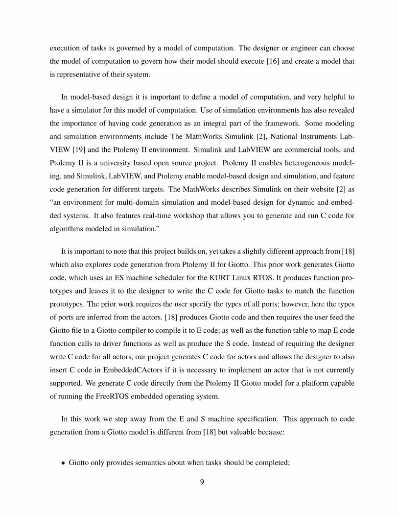
execution of tasks is governed by a model of computation. The designer or engineer can choose
the model of computation to govern how their model should execute [16] and create a model that
is representative of their system.
In model-based design it is important to define a model of computation, and very helpful to
have a simulator for this model of computation. Use of simulation environments has also revealed
the importance of having code generation as an integral part of the framework. Some modeling
and simulation environments include The MathWorks Simulink [2], National Instruments Lab-
VIEW [19] and the Ptolemy II environment. Simulink and LabVIEW are commercial tools, and
Ptolemy II is a university based open source project. Ptolemy II enables heterogeneous model-
ing, and Simulink, LabVIEW, and Ptolemy enable model-based design and simulation, and feature
code generation for different targets. The MathWorks describes Simulink on their website [2] as
“an environment for multi-domain simulation and model-based design for dynamic and embed-
ded systems. It also features real-time workshop that allows you to generate and run C code for
algorithms modeled in simulation.”
It is important to note that this project builds on, yet takes a slightly different approach from [18]
which also explores code generation from Ptolemy II for Giotto. This prior work generates Giotto
code, which uses an ES machine scheduler for the KURT Linux RTOS. It produces function pro-
totypes and leaves it to the designer to write the C code for Giotto tasks to match the function
prototypes. The prior work requires the user specify the types of all ports; however, here the types
of ports are inferred from the actors. [18] produces Giotto code and then requires the user feed the
Giotto file to a Giotto compiler to compile it to E code; as well as the function table to map E code
function calls to driver functions as well as produce the S code. Instead of requiring the designer
write C code for all actors, our project generates C code for actors and allows the designer to also
insert C code in EmbeddedCActors if it is necessary to implement an actor that is not currently
supported. We generate C code directly from the Ptolemy II Giotto model for a platform capable
of running the FreeRTOS embedded operating system.
In this work we step away from the E and S machine specification. This approach to code
generation from a Giotto model is different from [18] but valuable because:
• Giotto only provides semantics about when tasks should be completed;
9

• E code is used for portability to multiple targets and S code because most platforms provide
no direct control over when tasks execute;
• We attain portability by using the Ptolemy II model as our specification;
• E code and S code still require interpreters for your particular target;
• C code or code for a programming language still needs to be generated for the functionality
of tasks as well as for drivers and the execution of the generated code.
Instead of using E code and S code, we use the model specified in Ptolemy II as our portability
mechanism to multiple targets, and generate C code directly from the model specification since
our target RTOS provides direct control over timing. The objectives of this project are to generate
C code that adheres to Giotto semantics, but also to:
• Continue extending the C code generation framework in Ptolemy II for multiple targets;
• Build on existing work which allows the reuse of actors whenever possible;
• Allow the customization of actors to the target when necessary;
• Allow the user to easily create actors or to embed C code in an EmbeddedCActor and still
utilize the code generation facilities in Ptolemy II.
With the use of a scheduler, we generate C code directly from the model and forgo the speci-
fication of the Embedded Machine code since that information is also provided by the Ptolemy II
Giotto model. In our design we incorporate aspects normally handled by the E and S machine by
using the API tools offered by FreeRTOS.
In this report we discuss our ability to implement Giotto semantics using code generation and
a real-time operating system. We illustrate these techniques with Ptolemy II and the FreeRTOS
embedded operating system. To illustrate these techniques we extend the code generation frame-
work within Ptolemy II to generate C code for the Giotto programming model. Giotto, Ptolemy II,
and FreeRTOS are discussed in greater detail in Section 2. Section 3 discusses the extension of the
Ptolemy II code generation framework and the design of the scheduler, Section 3.6 discusses the
10
limitations of the work, Section 4 presents a controller application, and Section 5 discusses future
work.
2 Background
In this section we provide an overview of the Giotto model of computation, introduce the Ptolemy
II framework, present the Giotto implementation in Ptolemy II, and briefly give an overview of
FreeRTOS, the embedded OS target for the Giotto C code generator.
2.1 Giotto
Giotto is a programming model for embedded control systems [14], and is most useful for hard
real-time specifications that are periodic and feature multi-modal behavior. Giotto is useful for
control systems such as fly-by-wire or brake-by-wire where the responses of the system must be
periodic and there are multiple modes of operation. Examples of common modes of operation in
the automobiles include startup, cruise control, normal operation, and a degraded operation mode
in case of partial equipment failure. Giotto serves as a contract between a control engineer and
a software engineer to produce the behavior specified by the Giotto model. In addition, Giotto
allows the control engineer and software engineer to communicate effectively without the need to
get into implementation details. Control systems are generally specified using commercial tools
such as Simulink [2], or control engineers may manipulate differential equations and modal logic
with mathematical tools.
Giotto allows some flexibility in implementation as long the implementation conforms to the
timing specification. In fact Giotto does not specify how a program should be implemented on a
particular platform. Instead, it allows the user to specify the semantics of time-triggered sensor
readings, task invocations, actuator updates, and mode switches independent of the platform used
to implement it [14, 15]. As a result, Giotto tasks can be scheduled on platforms with a single CPU,
which use preemptive priority driven multitasking, or time-slicing, or on a platform with multiple
CPUs.
11

Figure 1: Task Invocation. Reused with permission [14].
One should note that a giotto program is schedulable, or will execute correctly, if there exists
a scheduling policy that will meet the requested deadlines on a particular processor given its re-
sources and time constraints [15]. Before producing a schedule, the Giotto compiler or scheduler
must ensure that the cumulative worst-case execution times of tasks in a mode, or the total time to
execute, is less than or equal to the logical execution time of a mode. The logical execution time
of a mode is the rate of execution specified by the mode’s periodic behavior. The Giotto compiler
just needs to ensure that sensors and actuators are written at the times requested in the Giotto se-
mantics. It is possible to add tasks to a mode without changing the code behavior as long as the
processor can accommodate the additional load [13].
Giotto code is generally executed on virtual execution engines [15] referred to as an Embedded
(E) machine and a Scheduling (S) machine. The virtual execution engines are necessary because
most widely available platforms do not have direct support for precise timing semantics. A Giotto
compiler produces E code for the E machine and S code for the S machine. E code provides
the “deadlines or release times of tasks” [15] and reacts to the platform’s passage of time. At a
deadline, the E code generally calls a function referred to as a driver that reads values at sensors
or writes values to the outside world at actuators. S code specifies a “feasible schedule” of the
deadlines specified by E code. Depending on the scheduling mechanism of a platform, S code may
run a task for a small amount of time and resume the task at a later time, or it may run a task until
completion. Some implementations of a Giotto environment combine the E and S machine; when
combined they are referred to as schedule carrying code [15].
To obtain a better understanding of Giotto it is essential that we explore the basics of the Giotto
programming model. In Giotto, a task, graphically represented in Figure 1, is the basic functional
12
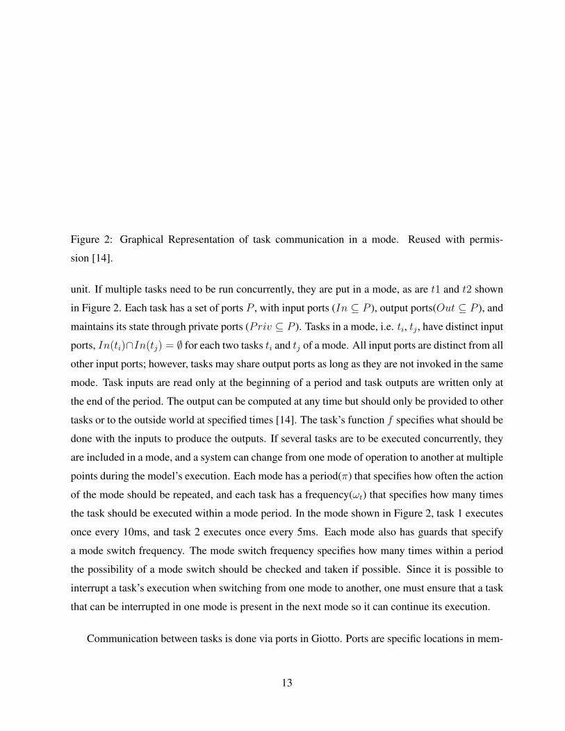
Figure 2: Graphical Representation of task communication in a mode. Reused with permis-
sion [14].
unit. If multiple tasks need to be run concurrently, they are put in a mode, as are t1 and t2 shown
in Figure 2. Each task has a set of ports P , with input ports (In ⊆ P ), output ports(Out ⊆ P ), and
maintains its state through private ports (Priv ⊆ P ). Tasks in a mode, i.e. ti, tj , have distinct input
ports, In(ti)∩In(tj) = ∅ for each two tasks ti and tj of a mode. All input ports are distinct from all
other input ports; however, tasks may share output ports as long as they are not invoked in the same
mode. Task inputs are read only at the beginning of a period and task outputs are written only at
the end of the period. The output can be computed at any time but should only be provided to other
tasks or to the outside world at specified times [14]. The task’s function f specifies what should be
done with the inputs to produce the outputs. If several tasks are to be executed concurrently, they
are included in a mode, and a system can change from one mode of operation to another at multiple
points during the model’s execution. Each mode has a period(π) that specifies how often the action
of the mode should be repeated, and each task has a frequency(ωt) that specifies how many times
the task should be executed within a mode period. In the mode shown in Figure 2, task 1 executes
once every 10ms, and task 2 executes once every 5ms. Each mode also has guards that specify
a mode switch frequency. The mode switch frequency specifies how many times within a period
the possibility of a mode switch should be checked and taken if possible. Since it is possible to
interrupt a task’s execution when switching from one mode to another, one must ensure that a task
that can be interrupted in one mode is present in the next mode so it can continue its execution.
Communication between tasks is done via ports in Giotto. Ports are specific locations in mem-
13

ory or variables dedicated to storing information. Drivers specify which output values should be
copied to specific ports and which port values should be copied from a port to an input. Ports hold
their value over time until they are updated by a driver. Sensor ports are updated by the environ-
ment, and actuator ports and task ports are updated by the program [14]. Task ports communicate
data between concurrent tasks and can also be used to communicate between modes in the event
of a mode switch. Mode ports are given a value every time the mode is entered [14]. In Figure 2,
o1 − o5 are mode ports. o1 is read when the mode begins and o2 − o5 are updated every 10ms and
can be used to pass information from one mode to another in the event of a mode switch. In Fig-
ure 2, fi specifies the actions that should be taken on the inputs to produce outputs, wact specifies
actuation frequency, and di specifies drivers which move information from ports to inputs, or from
outputs to an actuator.
2.1.1 Related Work
Giotto appears to have been influenced by Harel’s state charts [12], which extend state transition
diagrams and add notions of hierarchy, concurrency and communication. Giotto was also influ-
enced by the Time-Triggered Architecture(TTA), since TTA meets hard real-time requirements in
distributed systems and is based on the time-triggered programming model. TTA was intended for
similar applications as Giotto such as brake-by-wire or the control of an airplane. While Giotto
splits things into tasks, TTA splits things up into clusters and nodes. TTA provides a “fault-tolerant
global time base with known precision” [17] at each node. In TTA, all events that occur within a
certain interval of time are interpreted as occurring simultaneously and events that occur outside
the interval can be ordered [17]. Giotto differs from TTA since it comes with a hardware and
protocol independent programming model for time-triggered applications [14].
FlexRay, a bus architecture, has also been influenced by TTA. FlexRay is the latest system
being used for communication between various control devices in automobiles. FlexRay is time-
triggered and employs time division multiple access (TDMA) for arbitration between multiple
nodes on a bus. This communication was traditionally being done with a Control Area Network
(CAN); however, as more of the automotive industry adopts brake-by-wire/X-by-wire, as is done
in many airplanes, error and fault detection needs surpass the feasibility of CAN, and provides
support for the FlexRay protocol.
14

The Timing Definition Language (TDL) is a derivative of Giotto. TDL is a programming model
for concurrent hard real-time software. Like Giotto, in TDL sensor and actuator ports are used to
interact with the environment, a program is in one of many possible modes, every mode consists of
periodic activities, a mode has a fixed period, and timing and interaction of activities follow logical
execution time semantics [24]. Unlike Giotto, TDL provides a top-level structure called a module.
A module consists of actuators, sensors and modes. According to Derler et. al. modules are useful
for distributed applications, where it is possible to break the specification into smaller components
to be executed in parallel on different processors [20]. Giotto limits the number of mode switch
conditions that may evaluate to true to one to provide determinism; however, in TDL “mode switch
guards are evaluated in the textual order from top to bottom and a mode switch is performed for
the condition that evaluates to true [20].” Directors for Giotto and TDL are implemented in the
Ptolemy II simulation framework. An in-depth discussion of the TDL director in Ptolemy II is
in [20] and the Giotto implementation in Ptolemy II is presented in Section 2.3.
2.2 Ptolemy II
Ptolemy II [23] is an open source modeling and simulation framework being developed at the
University of California-Berkeley that supports model-based design. Ptolemy II facilitates actor
oriented and object oriented modeling. Actor oriented modeling is an alternative to the estab-
lished object oriented methodology, where actors allow actions to take place on the evolving data
which flows through them [8]. Ptolemy II facilitates the modeling and simulation of the design
of a real-time embedded system. The design can be concurrent, and a design’s behavior is gov-
erned by models of computation implemented in the Ptolemy II framework. A small subset of the
models of computation relevant to this project include: DE: discrete-event modeling; FSM: finite
state machines and modal models; SDF: synchronous data flow; TDL: timed description language;
and Giotto: periodic time-driven. Ptolemy II also has heterogeneous capabilities which allow the
designer to combine different models of computation.
In Ptolemy II, when an actor fires, its behavior for a particular model of computation is gov-
erned by a director which is specified for the particular model of computation. A designer can
select the director that specifies the desired behavior of a model, and then create and simulate their
15
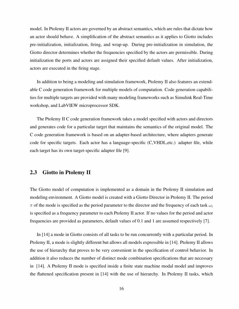
model. In Ptolemy II actors are governed by an abstract semantics, which are rules that dictate how
an actor should behave. A simplification of the abstract semantics as it applies to Giotto includes
pre-initialization, initialization, firing, and wrap-up. During pre-initialization in simulation, the
Giotto director determines whether the frequencies specified by the actors are permissible. During
initialization the ports and actors are assigned their specified default values. After initialization,
actors are executed in the firing stage.
In addition to being a modeling and simulation framework, Ptolemy II also features an extend-
able C code generation framework for multiple models of computation. Code generation capabili-
ties for multiple targets are provided with many modeling frameworks such as Simulink Real-Time
workshop, and LabVIEW microprocessor SDK.
The Ptolemy II C code generation framework takes a model specified with actors and directors
and generates code for a particular target that maintains the semantics of the original model. The
C code generation framework is based on an adapter-based architecture, where adapters generate
code for specific targets. Each actor has a language-specific (C,VHDL,etc.) adapter file, while
each target has its own target-specific adapter file [9].
2.3 Giotto in Ptolemy II
The Giotto model of computation is implemented as a domain in the Ptolemy II simulation and
modeling environment. A Giotto model is created with a Giotto Director in Ptolemy II. The period
π of the mode is specified as the period parameter to the director and the frequency of each task ωt
is specified as a frequency parameter to each Ptolemy II actor. If no values for the period and actor
frequencies are provided as parameters, default values of 0.1 and 1 are assumed respectively [7].
In [14] a mode in Giotto consists of all tasks to be run concurrently with a particular period. In
Ptolemy II, a mode is slightly different but allows all models expressible in [14]. Ptolemy II allows
the use of hierarchy that proves to be very convenient in the specification of control behavior. In
addition it also reduces the number of distinct mode combination specifications that are necessary
in [14]. A Ptolemy II mode is specified inside a finite state machine modal model and improves
the flattened specification present in [14] with the use of hierarchy. In Ptolemy II tasks, which
16

are referred to as actors, at the same level of hierarchy execute concurrently and a modal model
contains tasks that should be switched when a guard is enabled. If it is desirable to have three
tasks: A, B, and C, where task A is always running and task C should replace task B when a
certain condition is met, a designer could specify that in Ptolemy II as is shown in Figure 4. The
lower portion of Figure 4 shows how the model is specified with Ptolemy II and the upper portion
of the figure shows the logical execution times of each task based on their frequencies, and on the
period parameter π of the Giotto Director.
Ptolemy II allows hierarchy through the use of composite actors. A composite actor contains
actors and in some cases a director. If no director is present inside the composite actor the actor is
transparent. If however there is a director present inside a composite actor the frequencies of the
tasks inside the composite actor are all interpreted to be relative to the frequency of the composite
actor itself. If a composite actor with frequency 2 contains a Giotto Director, and a task with
frequency 3, the interpreted frequency of the task inside a composite actor is 6.
Each Giotto model is expected to specify a period as an attribute to the Giotto Director, the
frequency of each task as an attribute to each actor, as well as initial values for outputs. If Giotto
directors are used inside a composite actor, the period of the top most Giotto director is used, but
the frequencies of the tasks inside the composite actor are relative to the frequency of the composite
actor.
For the purposes of simulation it is also possible to set the number of times you wish to have the
model run. This can be specified as a parameter called iterations to the Giotto director. It should
be noted that since Ptolemy II allows hierarchical models, if another Giotto director is specified
within a composite actor, only the topmost Giotto director’s period parameter is used along with
the frequency parameters of each director and actor. One can run the model in the Ptolemy II
framework, insert a code generation actor to generate E Machine code [18], or insert a C Code
Generation actor to generate C code directly.
17

Figure 3: Simple Giotto Model in Ptolemy II with three actors
Mode 1 Mode 2
Mode 1
Task B Task B
Task A
∏0.5∏
0
∏
∏0.5∏0 0.25∏
Mode 2
Task A
Task C Task C Task C Task C
0.75∏
∏
frequency = 1 frequency = 1
frequency = 2 frequency = 4
Figure 4: Hierarchy
18

2.4 FreeRTOS
FreeRTOS was created by Richard Barry and the FreeRTOS team, and it is continually being de-
veloped and released. FreeRTOS is a “portable, open source, mini real-time kernel that can be used
in commercial applications [22].” It has versions available for a number of widely used microcon-
troller architectures, which makes the possibility of extending use and adoption of the Ptolemy
code generation infrastructure more promising. In addition, it “offers a smaller and easier real-
time processing alternative for applications where eCOS, embedded Linux (or Real-Time Linux),
and uCLinux cannot fit, are not appropriate, or are not available [22].”
FreeRTOS uses a prioritized preemptive scheduling policy that ensures that the highest pri-
ority task in the running state is the task given processing time. It has support for cooperative
scheduling and shares processor time equally between tasks of equal priority if they are able to run
simultaneously. As a result, FreeRTOS is a good target for a code generation framework. Some of
FreeRTOS’s features include: preemptive, cooperative, and hybrid configuration options; support
for tasks and coroutines; an execution trace functionality; stack overflow detection; queues; binary,
counting, and recursive semaphores; and mutexes which feature priority inheritance [22]. In addi-
tion to the general thread creation API expected in an RTOS, FreeRTOS also has API support to
set a periodic rate for the execution of a task with the vTaskDelayUntil method. In addition the
API provides methods to suspend and later resume the execution of tasks. These features make
FreeRTOS a very good match for the periodic nature of the Giotto.
3 Design
3.1 Framework Description
This work creates a Giotto adapter for the Ptolemy II C code generation framework [9]. A picture
of the framework applicable to this work is shown in Figure 5. Please note that dashed segments
of the framework have not currently been implemented for FreeRTOS. A user specifies the design
in Ptolemy II. By inserting and double-clicking on a CCodeGeneration actor, the user starts the C
19

Ptolemy II Specification
Giotto Director Ptolemy II
CodeGeneration
Framework
Schedulability
and WCET analysis
C program Targets
FreeRTOS Win 32
PRET MPI Posix
Figure 5: Design Framework
code generation framework, which can generate C code for different targets.
The generated code creates ports, actor variables, driver methods, task/actor code, as well as
scheduling and coordination code. Scheduling thread(s) as well as threads for each frequency in
the model are created. Scheduling threads mange a global notion of timing and let tasks know
when they can begin executing. Task code implements the behavior of Ptolemy II actors, and the
scheduling thread coordinates the execution of drivers and actor code.
3.2 Giotto C Code Generation
To generate C code for Giotto to run on the FreeRTOS platform, we created a Giotto Domain under
the C code generation folder, and also created a target-specific adapter for the Giotto Director as
well as a board-specific adapter implementation for the Timed Plotter actor. The C code generation
framework follows the pre-initialize, initialize,prefire, fire, and post fire semantics of Ptolemy II
and produces one C file that the user can compile and run on their target.
Each Giotto model is expected to specify a period as an attribute to the Giotto Director, the
frequency of each task as an attribute to each actor, as well as initial values for outputs. If a period
is not specified it defaults to 0.1 seconds, an unspecified frequency defaults to 1, and an unspecified
20

initial output value defaults to zero for integral types and null for other types. If Giotto directors are
used inside a composite actor, the period of the top-most Giotto director is used, but the frequencies
of the tasks inside the composite actor are relative to the frequency of the composite actor.
In the code generated, we attempt to use the facilities of the RTOS such as the fixed pri-
ority execution of threads ,where the processor is given to the thread with highest priority and
shares the processor between equal priority threads that are ready to run. We also utilize the
vTaskDelayUntil method in the FreeRTOS API. The vTaskDelayUntil method allows a task
to wait a specified number of kernel ticks from the last time it was called by the same task. The
vTaskDelayUntil method takes two parameters. We will call parameter 1, which is passed by ref-
erence, xLastWakeT ime and parameter 2 xFrequency. xLastWakeT ime is the value with the
last time the vTaskDelayUntil method was called. Prior to the first call to the vTaskDelayMethod
method the xLastWakeT ime parameter is initialized to the current kernel tick count. The sec-
ond parameter tells the number of kernel ticks since the last delay to yield the processor. In the
vTaskDelayUntil method, if the kernel tick count has passed xLastWakeT ime+xFrequency,
the method returns immediately without waiting. Otherwise it blocks for the necessary number
of kernel ticks to resume execution at xLastWakeT ime + xFrequency. As a result, A constant
value for xFrequency produces periodic execution of a thread.
Giotto code generation for FreeRTOS creates a thread for each distinct frequency specified
in a Giotto model. In addition it also creates a scheduler for each Giotto director. The sched-
uler is responsible for updating the ports of the actors/tasks specified in the Giotto models as
well as setting the initial global start time. Since we use a single thread to set the global start
time, we avoid the non determinism that would be possible with multiple concepts of time in each
thread. Since FreeRTOS is a single-processor fixed-priority RTOS, we benefit from the use of
the vTaskDelayUntil method in FreeRTOS that allows a method to “specify the exact time it
wishes to unblock, and allows cyclic tasks to ensure a constant execution frequency.” We use the
vTaskDelayUntil feature in each scheduler with an initial common start time, and use block-
ing semaphores in each scheduler as well as in task threads. The top most Giotto director in the
model is given it’s own scheduling thread. This scheduling thread is given the highest priority in
the system. Schedulers created for Giotto Directors in lower levels of the hierarchy are given a
priority equal to the priority of the actor that contains the Giotto refinement. threads created for
tasks with high frequencies are given higher priority in the fixed priority scheme than tasks with
21

lower frequency tasks.
In prior work [18], E machine code manages the deadline and releases of tasks. We accomplish
the same mechanism with the use of rate monotonic scheduling. In our approach we create a
scheduler for each Giotto director that calls driver methods at a specified rate. This is possible
because after processing the driver methods, the scheduler yields the processor to the next available
thread.
In some methods of code generated for a Giotto program, the S machine schedules a task to
be completed according to a specified frequency using either rate monotonic or earliest deadline
first scheduling. We use rate monotonic scheduling by assigning threads with higher frequency a
higher priority than lower frequency threads. After completing their tasks, each frequency thread
yields the processor until it is told by the scheduler it can begin execution.
For the very simple Giotto model shown in Figure 3, we generate a scheduling thread with the
highest priority in the system. The thread created to handle tasks with frequency 2 is given the
second highest priority, and the thread to handle tasks with frequency 1 is given the third highest
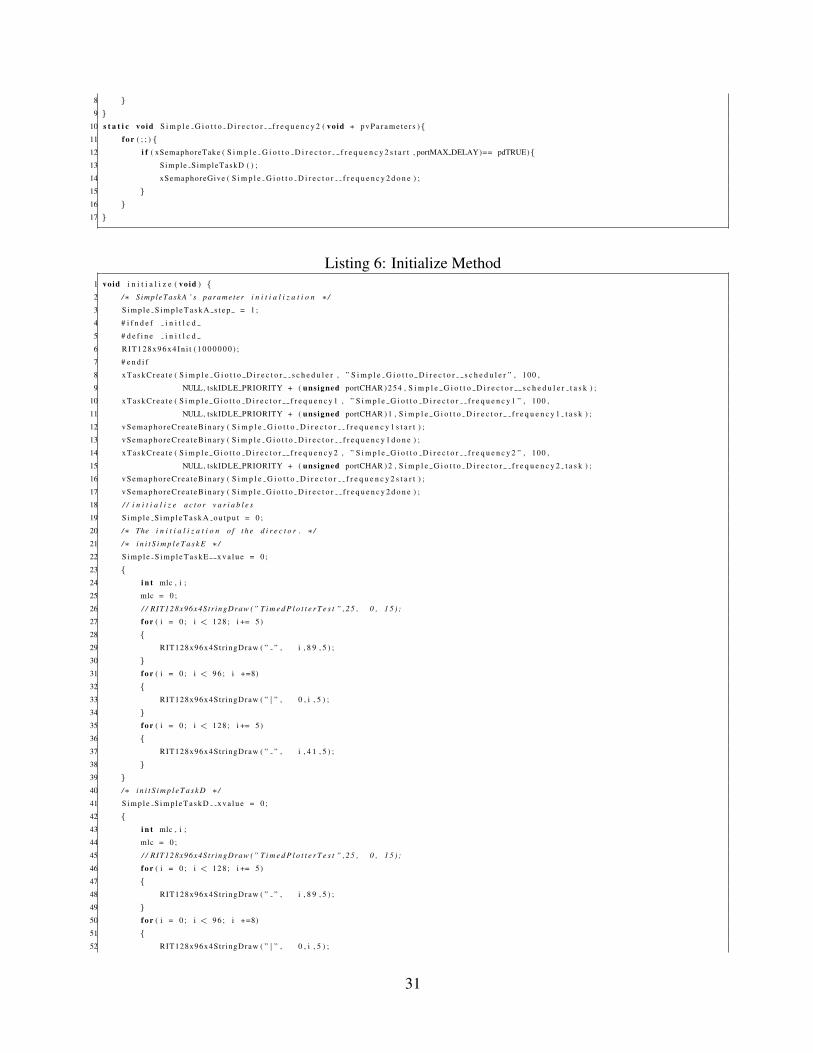
priority. The main method shown in Listing 7 calls the initialize method shown in Listing 6, which
initializes the necessary variables, and creates the scheduling and frequency threads. The main
method then calls the vTaskStartScheduler() method required to start threads in FreeRTOS. When
the FreeRTOS scheduler starts, it begins executing the thread with the highest priority, in this case
the scheduling thread. In the scheduling thread, we begin executing and set up the periodic exe-
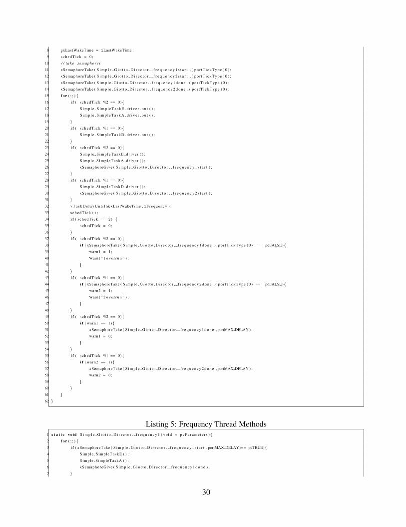
cution of the scheduler. Listings 1, 5, 4, 3, 2 show the respective variable declarations; frequency
methods, the scheduler method; actor methods; and driver methods generated for the Giotto model
show in Figure 3.
3.3 Scheduling
In our design, we assume each actor in the model has a parameter specifying its worst case exe-
cution time. If the parameter is not provided a default value is used. This information is used to
determine if the model can be run on a particular platform in the time requested. If the total WCET
for all actors in the model along with scheduling overhead is unable to complete in the desired
22
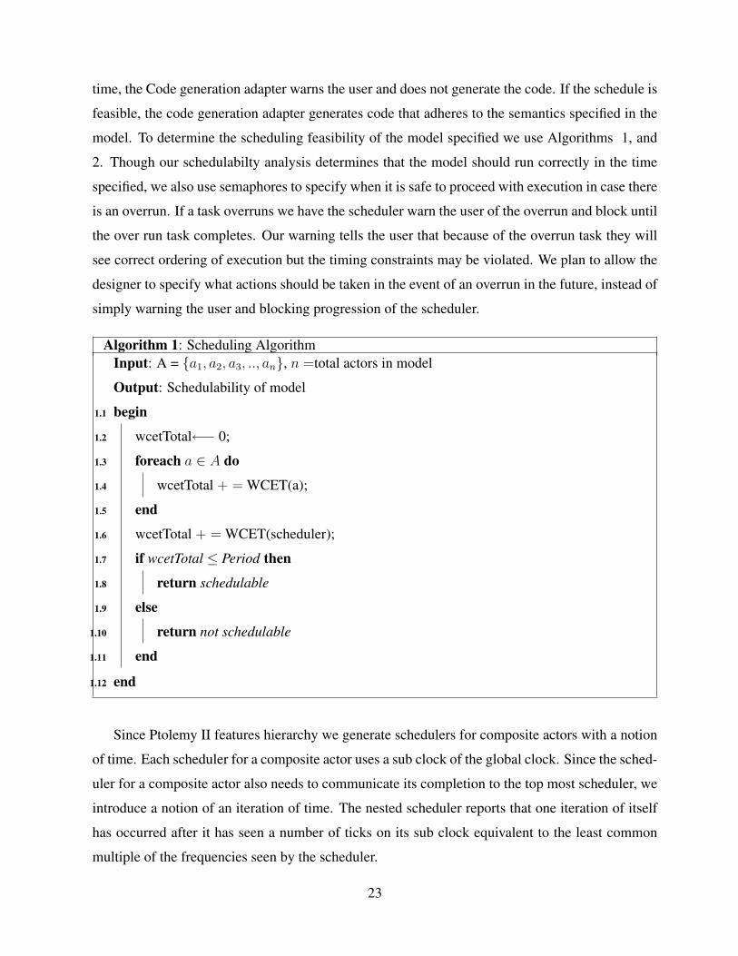
time, the Code generation adapter warns the user and does not generate the code. If the schedule is
feasible, the code generation adapter generates code that adheres to the semantics specified in the
model. To determine the scheduling feasibility of the model specified we use Algorithms 1, and
2. Though our schedulabilty analysis determines that the model should run correctly in the time
specified, we also use semaphores to specify when it is safe to proceed with execution in case there
is an overrun. If a task overruns we have the scheduler warn the user of the overrun and block until
the over run task completes. Our warning tells the user that because of the overrun task they will
see correct ordering of execution but the timing constraints may be violated. We plan to allow the
designer to specify what actions should be taken in the event of an overrun in the future, instead of
simply warning the user and blocking progression of the scheduler.
Algorithm 1: Scheduling AlgorithmInput: A = {a1, a2, a3, .., an}, n =total actors in model
Output: Schedulability of model
begin1.1
wcetTotal←− 0;1.2
foreach a ∈ A do1.3
wcetTotal + = WCET(a);1.4
end1.5
wcetTotal + = WCET(scheduler);1.6
if wcetTotal ≤ Period then1.7
return schedulable1.8
else1.9
return not schedulable1.10
end1.11
end1.12
Since Ptolemy II features hierarchy we generate schedulers for composite actors with a notion
of time. Each scheduler for a composite actor uses a sub clock of the global clock. Since the sched-
uler for a composite actor also needs to communicate its completion to the top most scheduler, we
introduce a notion of an iteration of time. The nested scheduler reports that one iteration of itself
has occurred after it has seen a number of ticks on its sub clock equivalent to the least common
multiple of the frequencies seen by the scheduler.
23
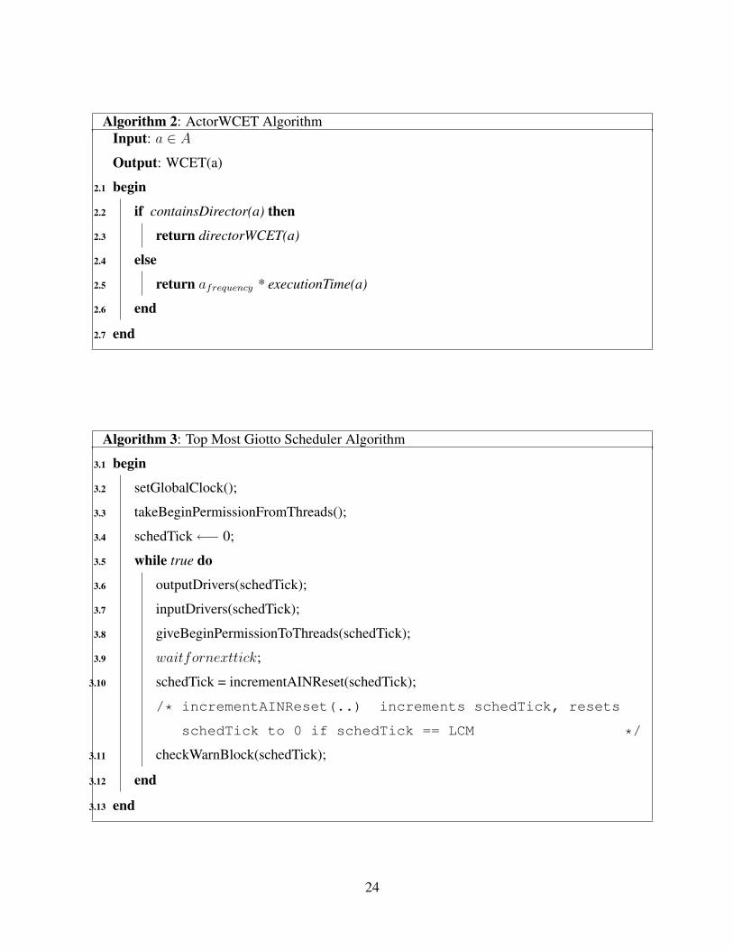
Algorithm 2: ActorWCET AlgorithmInput: a ∈ A
Output: WCET(a)
begin2.1
if containsDirector(a) then2.2
return directorWCET(a)2.3
else2.4
return afrequency * executionTime(a)2.5
end2.6
end2.7
Algorithm 3: Top Most Giotto Scheduler Algorithm
begin3.1
setGlobalClock();3.2
takeBeginPermissionFromThreads();3.3
schedTick←− 0;3.4
while true do3.5
outputDrivers(schedTick);3.6
inputDrivers(schedTick);3.7
giveBeginPermissionToThreads(schedTick);3.8
waitfornexttick;3.9
schedTick = incrementAINReset(schedTick);3.10
/* incrementAINReset(..) increments schedTick, resets
schedTick to 0 if schedTick == LCM */
checkWarnBlock(schedTick);3.11
end3.12
end3.13
24

Algorithm 4: Scheduler Algorithm
begin4.1
waituntil beginIterationMessage();4.2
readGlobalClock();4.3
takeBeginPermissionFromThreads();4.4
repeat4.5
outputDrivers(schedTick);4.6
inputDrivers(schedTick);4.7
giveBeginPermissionToThreads(schedTick);4.8
waitfornexttick;4.9
schedTick = incrementAINEIteration(schedTick);4.10
/* incrementAINEIteration(..) increments schedTick, and
says endOfIteration() if schedTick == LCM */
checkWarnBlock(schedTick);4.11
until endOfIteration() ;4.12
sendEndIterationMessage()4.13
end4.14
25
3.4 Current Design
The current Giotto C code generation adapter in Ptolemy II is able to generate code for a subset of
the actors in Ptolemy II; in addition, the adapter framework provides support for the Embedded-
CActor. The EmbeddedCActor allows the user to insert C code for any unimplemented actor on
their target and incorporates the C code into the final generated file. The current design also al-
lows the Synchronous Data Flow(SDF) model of computation to be used with Giotto. Each Giotto
director in a model is expected to have a period, and each actor is expected to have a frequency
specified. The frequency is how often a task should execute within a period. The types of ports
are inferred from the inputs provided or from the type the actor normally accepts or outputs. Also,
task code from each actor refers to its input and output variables. To transfer data from an output
to an input we use double buffering through an actor’s output variable and a port variable. Drivers
determine when values are copied from an output variable to a port and from port to an input
variable.
The scheduling thread is given the highest priority, and frequency threads are assigned a priority
lower than the scheduling thread. Each scheduler is called at the rate of the period divided by the
least common multiple of the frequencies in the mode. Each time it runs, a scheduler checks to
see if a previous run of tasks are complete, calls the driver methods of the actors to be run at
that particular time, sets semaphores indicating which frequency threads are safe to execute, and
releases the processor until the next necessary update. The scheduler then yields the processor to
the task threads and determines whether execution of the task(s) have finished. Currently, we block
until the semaphore is available.
The higher the frequency of the task, the higher the priority of the frequency thread it is assigned
to. Each frequency thread if given the go ahead from the scheduler, then calls the methods of the
tasks/actors to be executed at that frequency. The framework handles mode switches with the
modal model actor in Ptolemy II. The modal model actor is a finite state machine actor whose
states can be refined to contain other models. In this framework, the inner model can be either
SDF or Giotto.
When we generate code for a composite actor without a director, we treat the composite actor
as a transparent actor and generate code for its contents directly. When we generate code for com-
26
posite actors with a director, the frequencies of the actors inside the composite actor are set relative
to the composite actor’s frequency. When we set the frequency for the composite actor scheduler, it
is set equal to the period of the top - director, divided by the least common multiple of the frequen-
cies of the actors inside the composite actor, divided by the frequency of the composite actor. If
you have an example with a Giotto director, a source (constant output 1) with frequency 1, a com-
posite actor with frequency 2, and a timed plotter with frequency 2. The composite actor contains
a Giotto director, and an actor with frequency 3. The frequency for the composite actor sched-
uler xFrequency is (((1000/3)/2)/PortT ickRATEMS), where 1000/PortT ickRATEMS is
the converted period (1s) of the top most director in kernel ticks, 3 is the least common multiple of
the actor frequencies inside the composite actor, and 2 is the frequency of the composite actor.
Inside the scheduler we use a counter schedTick which determines which drivers are to be
executed on this run of the scheduler. The schedTick variable is initially zero, and is incre-
mented by 1 after running the drivers. The schedTick variable is reset to 0 when it is equal
to the least common multiple of the thread frequencies. Drivers are run if (schedT ick mod
(LCMofthreadfrequencies/frequencyoftask) == 0). A general algorithm for each sched-
uler is shown in Algorithm 3 and 4.
Since it is possible for the WCET specified to be too small, or in the case where there is
an overrun of the code being executed, we use semaphores to determine when it is safe to begin
execution of the code. In our scheduler we use a warn and block mechanism that displays a warning
message to the user, and then blocks until the overrun task completes its execution.
3.5 Drivers
Drivers are called by the scheduling thread, which has the highest priority in the system. The
framework currently assumes that task execution is shorter than the LET of the task. If a task
overruns its LET, the scheduling thread waits until the completion of the task before outputting the
value to the port, and reading a value from the port.
In this implementation, ports are written to at the beginning of a driver’s execution and values
are then transferred from the PORT to the desired inputs. This upholds the semantic that new
27

values are not read until the start of a mode period, but allows actuator output to occur as close as
possible to the beginning of a mode period.
3.6 Limitations
If WCET parameters are not provided for each actor we currently use a default value when we
calculate WCET. As a result, though our schedulability check may tell us that the desired schedule
is feasible, our assumption my indeed lead to overruns. If there are overruns we currently warn
the user, and and continue execution when the overrun tasks completes. If there are overruns,
the user will notice correct ordering of execution but will see a delay in outputs. As a result the
current implementation without accurate WCET parameters should not be used in safety critical
applications.
One should also note that there is a limit to the number of distinct frequencies that can be
supported since the thread’s frequency determines its priority; and priorities can only be assigned
values 1 through Scheduler Priority-1. Scheduler Priority is reserved for the scheduler of the top
most Giotto director. One should also note that executing the scheduling thread at a rate relative
to the least common multiple of frequencies of the actors in the model since execution may not be
necessary on every run of the scheduler. One alternative to this, which will be pursued in future
work, is to predetermine which ticks of the scheduler at the LCM frequency will need to execute
drivers and use that as the offset interval of the scheduler. One should also note that we currently
presume that each FreeRTOS thread created will use maximum constant amount of stack space. A
more efficient use of memory would perform an analysis of the content of the C code generated
for each actor to determine the maximum stack size necessary.
Listing 1: Actor and Port Variables1 /∗ S i m p l e S i m p l e T a s k E ’ s i n p u t v a r i a b l e d e c l a r a t i o n s . ∗ /
2 s t a t i c double S i m p l e S i m p l e T a s k E i n p u t [ 1 ] ;
3 /∗ S im p l e S i mp le Ta sk D ’ s i n p u t v a r i a b l e d e c l a r a t i o n s . ∗ /
4 s t a t i c double S i m p l e S i m p l e T a s k D i n p u t [ 1 ] ;
5 /∗ S i m p l e S i m p l e T a s k A ’ s r e f e r e n c e d parame te r d e c l a r a t i o n s . ∗ /
6 s t a t i c i n t S i m p l e S i m p l e T a s k A s t e p ;
7 /∗ S i m p l e S i m p l e T a s k A ’ s t y p e c o n v e r t v a r i a b l e d e c l a r a t i o n s . ∗ /
8 s t a t i c i n t S i m p l e S i m p l e T a s k A o u t p u t 0 ;
9 s t a t i c i n t S i m p l e S i m p l e T a s k A o u t p u t ;
10 s t a t i c i n t Simple SimpleTaskA output PORT ;
11 /∗ The p r e i n i t i a l i z a t i o n o f t h e d i r e c t o r . ∗ /
12 /∗ p r e i n i t S i m p l e T a s k E ∗ /
13 s t a t i c i n t S i m p l e S i m p l e T a s k E x v a l u e ;
28

14 /∗ p r e i n i t S i m p l e T a s k D ∗ /
15 s t a t i c i n t S i m p l e S i m p l e T a s k D x v a l u e ;
16 /∗ p r e i n i t S i m p l e T a s k A ∗ /
17 s t a t i c i n t S i m p l e S i m p l e T a s k A s t a t e ;
18 unsigned long g u l S y s t e m C l o c k ;
19 p o r t T i c k T y p e gxLastWakeTime ;
20 # i n c l u d e ” semphr . h ”
21 xTaskHandle S i m p l e G i o t t o D i r e c t o r s c h e d u l e r t a s k ;
22 xTaskHandle S i m p l e G i o t t o D i r e c t o r f r e q u e n c y 1 t a s k ;
23 xSemaphoreHandle S i m p l e G i o t t o D i r e c t o r f r e q u e n c y 1 s t a r t ;
24 xSemaphoreHandle S i m p l e G i o t t o D i r e c t o r f r e q u e n c y 1 d o n e ;
25 xTaskHandle S i m p l e G i o t t o D i r e c t o r f r e q u e n c y 2 t a s k ;
26 xSemaphoreHandle S i m p l e G i o t t o D i r e c t o r f r e q u e n c y 2 s t a r t ;
27 xSemaphoreHandle S i m p l e G i o t t o D i r e c t o r f r e q u e n c y 2 d o n e ;
Listing 2: Driver Methods1
2 void S i m p l e S i m p l e T a s k E d r i v e r o u t ( ) {3
4 }5 void S i m p l e S i m p l e T a s k D d r i v e r o u t ( ) {6
7 }8 void S i m p l e S i m p l e T a s k A d r i v e r o u t ( ) {9 Simple SimpleTaskA output PORT = S i m p l e S i m p l e T a s k A o u t p u t ;
10 }11 void S i m p l e S i m p l e T a s k E d r i v e r ( ){12 S i m p l e S i m p l e T a s k E i n p u t [ 0 ] = I n t t o D o u b l e ( S imple SimpleTaskA output PORT ) ;
13 }14 void S i m p l e S i m p l e T a s k D d r i v e r ( ){15 S i m p l e S i m p l e T a s k D i n p u t [ 0 ] = I n t t o D o u b l e ( S imple SimpleTaskA output PORT ) ;
16 }17 void S i m p l e S i m p l e T a s k A d r i v e r ( ){18 }
Listing 3: Actor Methods1 void Simple S impleTaskE ( ) {2 P l o t P o i n t 1 ( S i m p l e S i m p l e T a s k E x v a l u e , S i m p l e S i m p l e T a s k E i n p u t [ 0 ] ) ;
3 S i m p l e S i m p l e T a s k E x v a l u e ++;
4 }5
6 void Simple SimpleTaskD ( ) {7 P l o t P o i n t 2 ( S im p le S im p le T as k D x va l ue , S i m p l e S i m p l e T a s k D i n p u t [ 0 ] ) ;
8 S i m p l e S i m p l e T a s k D x v a l u e ++;
9 }10
11 void Simple SimpleTaskA ( ) {12 S i m p l e S i m p l e T a s k A o u t p u t = S i m p l e S i m p l e T a s k A s t a t e ;
13 S i m p l e S i m p l e T a s k A s t a t e = a d d I n t I n t ( S i m p l e S i m p l e T a s k A s t a t e , S i m p l e S i m p l e T a s k A s t e p ) ;
14 }
Listing 4: Scheduler Thread Methods1 s t a t i c vo id S i m p l e G i o t t o D i r e c t o r s c h e d u l e r ( void ∗ p v P a r a m e t e r s ){2 p o r t T i c k T y p e xLastWakeTime ;
3 i n t s c h e d T i c k ;
4 c o n s t p o r t T i c k T y p e xFrequency = ( ( ( 1 0 0 / 2 ) / 1 ) / portTICK RATE MS ) ;
5 char warn1 = 0 ;
6 char warn2 = 0 ;
7 xLastWakeTime = xTaskGetTickCount ( ) ;
29
8 gxLastWakeTime = xLastWakeTime ;
9 s c h e d T i c k = 0 ;
10 / / t a k e semaphores
11 xSemaphoreTake ( S i m p l e G i o t t o D i r e c t o r f r e q u e n c y 1 s t a r t , ( p o r t T i c k T y p e ) 0 ) ;
12 xSemaphoreTake ( S i m p l e G i o t t o D i r e c t o r f r e q u e n c y 2 s t a r t , ( p o r t T i c k T y p e ) 0 ) ;
13 xSemaphoreTake ( S i m p l e G i o t t o D i r e c t o r f r e q u e n c y 1 d o n e , ( p o r t T i c k T y p e ) 0 ) ;
14 xSemaphoreTake ( S i m p l e G i o t t o D i r e c t o r f r e q u e n c y 2 d o n e , ( p o r t T i c k T y p e ) 0 ) ;
15 f o r ( ; ; ){16 i f ( s c h e d T i c k %2 == 0){17 S i m p l e S i m p l e T a s k E d r i v e r o u t ( ) ;
18 S i m p l e S i m p l e T a s k A d r i v e r o u t ( ) ;
19 }20 i f ( s c h e d T i c k %1 == 0){21 S i m p l e S i m p l e T a s k D d r i v e r o u t ( ) ;
22 }23 i f ( s c h e d T i c k %2 == 0){24 S i m p l e S i m p l e T a s k E d r i v e r ( ) ;
25 S i m p l e S i m p l e T a s k A d r i v e r ( ) ;
26 xSemaphoreGive ( S i m p l e G i o t t o D i r e c t o r f r e q u e n c y 1 s t a r t ) ;
27 }28 i f ( s c h e d T i c k %1 == 0){29 S i m p l e S i m p l e T a s k D d r i v e r ( ) ;
30 xSemaphoreGive ( S i m p l e G i o t t o D i r e c t o r f r e q u e n c y 2 s t a r t ) ;
31 }32 v T a s k D e l a y U n t i l (&xLastWakeTime , xFrequency ) ;
33 s c h e d T i c k ++;
34 i f ( s c h e d T i c k == 2) {35 s c h e d T i c k = 0 ;
36 }37 i f ( s c h e d T i c k %2 == 0){38 i f ( xSemaphoreTake ( S i m p l e G i o t t o D i r e c t o r f r e q u e n c y 1 d o n e , ( p o r t T i c k T y p e ) 0 ) == pdFALSE){39 warn1 = 1 ;
40 Warn ( ” 1 o v e r r u n ” ) ;
41 }42 }43 i f ( s c h e d T i c k %1 == 0){44 i f ( xSemaphoreTake ( S i m p l e G i o t t o D i r e c t o r f r e q u e n c y 2 d o n e , ( p o r t T i c k T y p e ) 0 ) == pdFALSE){45 warn2 = 1 ;
46 Warn ( ” 2 o v e r r u n ” ) ;
47 }48 }49 i f ( s c h e d T i c k %2 == 0){50 i f ( warn1 == 1){51 xSemaphoreTake ( S i m p l e G i o t t o D i r e c t o r f r e q u e n c y 1 d o n e , portMAX DELAY ) ;
52 warn1 = 0 ;
53 }54 }55 i f ( s c h e d T i c k %1 == 0){56 i f ( warn2 == 1){57 xSemaphoreTake ( S i m p l e G i o t t o D i r e c t o r f r e q u e n c y 2 d o n e , portMAX DELAY ) ;
58 warn2 = 0 ;
59 }60 }61 }62 }
Listing 5: Frequency Thread Methods1 s t a t i c vo id S i m p l e G i o t t o D i r e c t o r f r e q u e n c y 1 ( void ∗ p v P a r a m e t e r s ){2 f o r ( ; ; ){3 i f ( xSemaphoreTake ( S i m p l e G i o t t o D i r e c t o r f r e q u e n c y 1 s t a r t , portMAX DELAY)== pdTRUE){4 Simple S impleTaskE ( ) ;
5 Simple SimpleTaskA ( ) ;
6 xSemaphoreGive ( S i m p l e G i o t t o D i r e c t o r f r e q u e n c y 1 d o n e ) ;
7 }
30
8 }9 }
10 s t a t i c vo id S i m p l e G i o t t o D i r e c t o r f r e q u e n c y 2 ( void ∗ p v P a r a m e t e r s ){11 f o r ( ; ; ){12 i f ( xSemaphoreTake ( S i m p l e G i o t t o D i r e c t o r f r e q u e n c y 2 s t a r t , portMAX DELAY)== pdTRUE){13 Simple SimpleTaskD ( ) ;
14 xSemaphoreGive ( S i m p l e G i o t t o D i r e c t o r f r e q u e n c y 2 d o n e ) ;
15 }16 }17 }
Listing 6: Initialize Method1 void i n i t i a l i z e ( void ) {2 /∗ SimpleTaskA ’ s parame te r i n i t i a l i z a t i o n ∗ /
3 S i m p l e S i m p l e T a s k A s t e p = 1 ;
4 # i f n d e f i n i t l c d
5 # d e f i n e i n i t l c d
6 RIT128x96x4In i t ( 1 0 0 0 0 0 0 ) ;
7 # e n d i f
8 x T a s k C r e a t e ( S i m p l e G i o t t o D i r e c t o r s c h e d u l e r , ” S i m p l e G i o t t o D i r e c t o r s c h e d u l e r ” , 100 ,
9 NULL, tskIDLE PRIORITY + ( unsigned portCHAR ) 2 5 4 , S i m p l e G i o t t o D i r e c t o r s c h e d u l e r t a s k ) ;
10 x T a s k C r e a t e ( S i m p l e G i o t t o D i r e c t o r f r e q u e n c y 1 , ” S i m p l e G i o t t o D i r e c t o r f r e q u e n c y 1 ” , 100 ,
11 NULL, tskIDLE PRIORITY + ( unsigned portCHAR ) 1 , S i m p l e G i o t t o D i r e c t o r f r e q u e n c y 1 t a s k ) ;
12 vSemaphoreCrea t eB ina ry ( S i m p l e G i o t t o D i r e c t o r f r e q u e n c y 1 s t a r t ) ;
13 vSemaphoreCrea t eB ina ry ( S i m p l e G i o t t o D i r e c t o r f r e q u e n c y 1 d o n e ) ;
14 x T a s k C r e a t e ( S i m p l e G i o t t o D i r e c t o r f r e q u e n c y 2 , ” S i m p l e G i o t t o D i r e c t o r f r e q u e n c y 2 ” , 100 ,
15 NULL, tskIDLE PRIORITY + ( unsigned portCHAR ) 2 , S i m p l e G i o t t o D i r e c t o r f r e q u e n c y 2 t a s k ) ;
16 vSemaphoreCrea t eB ina ry ( S i m p l e G i o t t o D i r e c t o r f r e q u e n c y 2 s t a r t ) ;
17 vSemaphoreCrea t eB ina ry ( S i m p l e G i o t t o D i r e c t o r f r e q u e n c y 2 d o n e ) ;
18 / / i n i t i a l i z e a c t o r v a r i a b l e s
19 S i m p l e S i m p l e T a s k A o u t p u t = 0 ;
20 /∗ The i n i t i a l i z a t i o n o f t h e d i r e c t o r . ∗ /
21 /∗ i n i t S i m p l e T a s k E ∗ /
22 S i m p l e S i m p l e T a s k E x v a l u e = 0 ;
23 {24 i n t mlc , i ;
25 mlc = 0 ;
26 / / RIT128x96x4Str ingDraw (” T i m e d P l o t t e r T e s t ” ,25 , 0 , 1 5 ) ;
27 f o r ( i = 0 ; i < 128 ; i += 5)
28 {29 RIT128x96x4Str ingDraw ( ” ” , i , 8 9 , 5 ) ;
30 }31 f o r ( i = 0 ; i < 9 6 ; i +=8)
32 {33 RIT128x96x4Str ingDraw ( ” | ” , 0 , i , 5 ) ;
34 }35 f o r ( i = 0 ; i < 128 ; i += 5)
36 {37 RIT128x96x4Str ingDraw ( ” ” , i , 4 1 , 5 ) ;
38 }39 }40 /∗ i n i t S i m p l e T a s k D ∗ /
41 S i m p l e S i m p l e T a s k D x v a l u e = 0 ;
42 {43 i n t mlc , i ;
44 mlc = 0 ;
45 / / RIT128x96x4Str ingDraw (” T i m e d P l o t t e r T e s t ” ,25 , 0 , 1 5 ) ;
46 f o r ( i = 0 ; i < 128 ; i += 5)
47 {48 RIT128x96x4Str ingDraw ( ” ” , i , 8 9 , 5 ) ;
49 }50 f o r ( i = 0 ; i < 9 6 ; i +=8)
51 {52 RIT128x96x4Str ingDraw ( ” | ” , 0 , i , 5 ) ;
31

53 }54 f o r ( i = 0 ; i < 128 ; i += 5)
55 {56 RIT128x96x4Str ingDraw ( ” ” , i , 4 1 , 5 ) ;
57 }58 }59 /∗ i n i t S i m p l e T a s k A ∗ /
60 S i m p l e S i m p l e T a s k A s t a t e = c o n v e r t I n t I n t ( 0 ) ;
61
62 }
Listing 7: Main Method1 i n t main ( i n t argc , char ∗a rgv [ ] ) {2 i n i t i a l i z e ( ) ;
3 g u l S y s t e m C l o c k = S y s C t l C l o c k G e t ( ) ;
4 v T a s k S t a r t S c h e d u l e r ( ) ;
5 e x i t ( 0 ) ;
6 }
4 Case Study in Elevator Control
As a demonstration of the use of the Giotto C Code Generator for FreeRTOS, we specify a model
of a simple elevator controller in Ptolemy II, and generate code for FreeRTOS from the model.
This example implements a variant of the Toy Elevator problem specified for the Spin [1] Model
checker. The controls are for a very simple elevator that services four floors of a building. The
elevator is initially on the first floor, and it remains on the last floor requested by the user with its
doors open awaiting user input. This example demonstrates only a subset of the capabilities of
the code generator but effectively demonstrates multi modal behavior, even without refinements.
Interaction with the controller was done via a web page shown in Figure 6 being run on a web
server running on the Luminary Cortex-M3.
The status of the elevator door and floor are shown on the LCD screen. The controller details
are shown in Figures 7 and 8. The input constants for pending up, down, 1,2,3,4 are tied to inputs
from the web interface and the pending status variables are also used in the web server. It is
important to note that the code generation process creates one C file. Since for this application
the controls receive information from the web server, the variables for the input constants to the
controller as well as the status variables are moved to a common header file, seen by both the main
file and the web server.
32

Floor 4
Floor 3
Floor 2
Floor 1
Floor Selection Pannel
Elevator Controller fi le:///C:/Documents%20and%20Settings/Administrator/Desktop/index2....
1 of 1 4/29/2009 4:24 PM
Figure 6: Web Interface to the Elevator
Figure 7: Top Level of Specification
33

Figure 8: States in the elevator controller34
This controller is simply a proof of concept, in fact it does not have the safety precautions
present in modern day elevators such as a bump sensor. It has an alarm, unlike the toy elevator
problem specified for the Spin Model checker, where the elevator stops, and outputs a sound to
indicate the alarm has gone off. One should note that if the alarm button is pressed it preempts all
other inputs.
Please note that we do not have WCET analysis available for the CortexM3 and that we are
also running the web server from the microprocessor. Additionally, we handle audio in the Systick
handler, the same handler used by FreeRTOS to handle the kernel. As a result we see correct
ordering of outputs however as is to be expected, audio is output at varying speeds. This indicates
the we would not be able to successfully play music if we attempted to use the code generator
without WCET analysis tool to play different portions of a song that need to be pieced together at
precise times.
5 Future Work
Current work indicates the potential for the direct use of a real-time operating system with timed
models of computation if the RTOS provides a mechanism for direct control over timing. We plan
to extend the code generation framework to do WCET analysis of a model before generating code
for FreeRTOS specifically for the Luminary board. If the WCET analysis reveals that the WCET of
tasks is longer than the LET, we plan to use utility functions to determine what should occur during
an overrun. Options include stalling until the task completes, resetting the processor if we presume
a fatal error has occurred because of the overrun, or continuing execution of the task if its execution
completes within a certain grace time. This change will step away from the direct mapping between
model time and physical time, which Giotto generally makes equivalent, and allows the exploration
of delays in processing, as long as the outputs to an actuator or a mode port are delivered in time.
This approach is similar to the approach taken in PTIDES, so there is the potential for concurrent
development of both projects. In addition we will explore mappings of Giotto to other systems
such as OSEK, a widely used RTOS in the automotive domain as well as pthreads, as long as they
allow some control over timing as FreeRTOS does. We will also demonstrate that the Software
Architecture of the Ptolemy II code generation framework is modular enough to allow easy re
35
targeting to another RTOS.
6 Acknowledgments
I would like to take the time to acknowledge a few people who have made the completion of
this project possible. I’d like to thank my advisor Professor Edward A. Lee for helping me to
identify the limitations of the work, pointing me in the right direction when my ideas went astray,
suggesting ways to strengthen the work and also for providing suggestions on one of the very first
drafts of this report. Next I would like to thank Professor Sanjit Seshia for his willingness to be my
second reader. I would also like to thank my group mates Ben Lickly and Man-Kit Leung who have
been available for many debugging and idea sessions, as well as patiently taking my questions as I
became familiar with Ptolemy II adapter framework. I would also like to thank group mates Hiren
D. Patel and Slobodan Matic for being willing to read and provide useful comments on drafts of
this report as well as for providing suggestions for possible applications for Giotto. Last but not
least I would like to thank my parents Doreen and Trevor Forbes for their wonderful support and
their continuous encouragement.
References
[1] Spin - Formal Verification. http://spinroot.com/spin/whatispin.html ,accessed May 10, 2009.
[2] The MathWorks website. http://www.mathworks.com/products/simulink/ ,accessed May 3,
2009.
[3] G. B. Albert Benveniste. The synchronous approach to reactive and real-time systems. In
Proceedings of the IEEE, pages 1270–1282, September 1991.
[4] C. ANDRE. Representation and analysis of reactive behaviors: A synchronous approach.
IEEE-SMC (Computational Engineering in Systems Applications, pages 19–29, July 1996.
36

[5] A. Benveniste, P. Le Guernic, and C. Jacquemot. Synchronous programming with events
and relations: the signal language and its semantics. Sci. Comput. Program., 16(2):103–149,
1991.
[6] F. Boussinot and R. de Simone. The ESTEREL language. Proceedings of the IEEE,
79(9):1293–1304, Sep 1991.
[7] C. Brooks, E. A. Lee, X. Liu, S. Neuendorffer, Y. Zhao, and H. Zheng. Heterogeneous
concurrent modeling and design in java (volume 3: Ptolemy ii domains). Technical Report
UCB/EECS-2008-37, EECS Department, University of California, Berkeley, Apr 2008.
[8] Edward A. Lee. Center for Hybrid and Embedded Software Systems Seminar on Model
Engineering, October 21 2008.
[9] M.-K. L. Gang Zhou and E. A. Lee. A code generation framework for actor-oriented models
with partial evaluation. In International Conference on Embedded Software and Systems,
LNCS 4523, pages pp. 786–799, May 2007.
[10] U. C. Group. Programming temporally integrated distributed embedded systems.
http://chess.eecs.berkeley.edu/ptides/, December 2007.
[11] N. Halbwachs, P. Caspi, P. Raymond, and D. Pilaud. The synchronous data flow programming
language lustre. Proceedings of the IEEE, 79(9):1305–1320, Sep 1991.
[12] D. Harel. Statecharts: A visual formalism for complex systems. In Science of Computer
Programming, 1987.
[13] T. Henzinger, C. Kirsch, M. Sanvido, and W. Pree. From control models to real-time code
using giotto. IEEE Control Systems Magazine, 23(1):50–64, January 2003.
[14] T. A. Henzinger, B. Horowitz, and C. M. Kirsch. Giotto: A time-triggered language for
embedded programming. volume 91(1) of Proceedings of the IEEE, pages 84–99, 2003.
[15] T. A. Henzinger, C. M. Kirsch, and S. Matic. Schedule-carrying code. In In Proc. EMSOFT,
LNCS 2855, pages 241–256. Springer, 2003.
[16] E. K. Jackson. The software engineering of domain-specific modeling languages: A survey
through examples. Technical Report ISIS-07-807, Vanderbilt Universtiy, March 2007.
37
[17] H. KOPETZ and G. BAUER. The time-triggered architecture. In Proceedings of the IEEE,
volume 91, pages 112–126, January 2003.
[18] N. V. Krishnan. Real-Time Systems Design in Ptolemy II: A Time-Triggered Approach.
Master’s thesis, University of California, Berkeley, Berkeley,CA 94720, July 2004.
[19] National Instruments Corporation. NI LabVIEW The Software that Powers Virtual Instru-
mentation. http://www.ni.com/labview.
[20] P. D. Stefan Resmerita and W. Pree. Timing definition language (tdl) modeling in ptolemy
ii. Technical Report Technical Report 21, Department of Computer Science, University of
Salzburg, June 2008.
[21] J. Sztipanovits and G. Karsai. Model-integrated computing. Computer, 30(4):110–111, Apr
1997.
[22] The FreeRTOS.org Project. Openrtos. http://www.freertos.org.
[23] The Ptolemy Project. http://ptolemy.eecs.berkeley.edu/.
[24] a. J. T. Wolfgang Pree. The Timing Definition Language, October 21 2005.
38