READY Draft and Venting Chapter · PDF fileDraft and Venting Chapter 6 Chapter 6—Draft...
19
Transcript of READY Draft and Venting Chapter · PDF fileDraft and Venting Chapter 6 Chapter 6—Draft...


Draft and VentingChapter 6
Chapter 6—Draft and Venting 6-3
Hot Air Causes Lower Weight (Pressure)at Bottom of Chimney than Cold Air
Figure 6-1:Chimney draft
Hot Chimney Cold Chimney
IntroductionAir is needed to burn oil cleanly and
efficiently. We must understand how tosupply air to the burner and how to ensurethat all of the gases created in burning thefuel are vented to the outside. Additionally,for non-condensing appliances, we mustmake sure the water vapor created duringcombustion is vented to the outside prior tocondensing.
What is draft?Draft is a current of air in an enclosed
area that is created by a difference inpressure. In practical terms, draft is a forcethat “pulls” or “sucks” the exhaust gasesout of the heating unit and sends them upthe chimney.
During the combustion process hotgases rise through the heating appliance tothe flue pipe and travel up the chimney,creating negative pressure or suction, alsoknown as “negative draft” at the bottom ofthe chimney.
The pressure difference is createdbecause:
• When the burner is off and the chim-ney is cold, the air inside the combustionarea, heat exchanger, flue pipe, andchimney is at atmospheric pressure.
• When the burner starts, the burner fancreates “static pressure” as it pushes air intothe combustion area where it combineswith the fuel to create a fire.
• When the air and fuel burn, thetemperature rises dramatically and thecombustion gases expand to more thandouble their volume. This expansivepressure adds to the pressure created by theburner fan and pushes the combustion gasesthrough the heat exchanger.
• As the hot combustion gases travel upthe chimney they create a pressure dropbehind them that sucks the combustiongases out of the heat exchanger, Figure 6-1.
Draft is the total effect of the positivepressures of the burner fan, the expansivepressure of the flame, and the negativepressure of the hot gases escaping the topof the chimney.
Chapter 6Draft and Venting
6-4 Draft and Venting
Oilburners need steady draftfor proper operation. Insufficientor variable draft can causeoperational problems. Forexample, a fire that pulsates or arumble in the appliance mayresult from insufficient draft.
Chimney ventingcreates natural draft
There are two types of naturaldraft created in the chimney—thermal and currential.
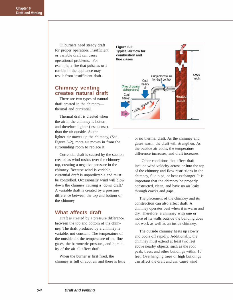
Thermal draft is created whenthe air in the chimney is hotter,and therefore lighter (less dense),than the air outside. As thelighter air moves up the chimney, (SeeFigure 6-2), more air moves in from thesurrounding room to replace it.
Currential draft is caused by the suctioncreated as wind rushes over the chimneytop, creating a negative pressure in thechimney. Because wind is variable,currential draft is unpredictable and mustbe controlled. Occasionally wind will blowdown the chimney causing a ‘down draft.’A variable draft is created by a pressuredifference between the top and bottom ofthe chimney.
What affects draftDraft is created by a pressure difference
between the top and bottom of the chim-ney. The draft produced by a chimney isvariable, not constant. The temperature ofthe outside air, the temperature of the fluegases, the barometric pressure, and humid-ity of the air all affect draft.
When the burner is first fired, thechimney is full of cool air and there is little
or no thermal draft. As the chimney andgases warm, the draft will strengthen. Asthe outside air cools, the temperaturedifference increases, and draft increases.
Other conditions that affect draftinclude wind velocity across or into the topof the chimney and flow restrictions in thechimney, flue pipe, or heat exchanger. It isimportant that the chimney be properlyconstructed, clean, and have no air leaksthrough cracks and gaps.
The placement of the chimney and itsconstruction can also affect draft. Achimney operates best when it is warm anddry. Therefore, a chimney with one ormore of its walls outside the building doesnot work as well as an inside chimney.
The outside chimney heats up slowlyand cools off rapidly. Additionally, thechimney must extend at least two feetabove nearby objects, such as the roofpeak, trees, and other buildings within 10feet. Overhanging trees or high buildingscan affect the draft and can cause wind
Figure 6-2:Typical air flow forcombustion andflue gases
Chapter 6Draft and Venting
Chapter 6—Draft and Venting 6-5
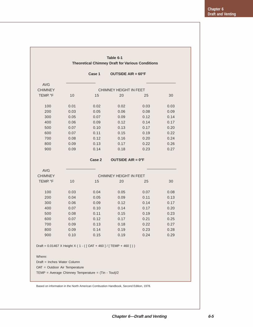
Table 6-1 Theoretical Chimney Draft for Various Conditions
Case 1 OUTSIDE AIR = 60°F
AVGCHIMNEY CHIMNEY HEIGHT IN FEET
TEMP. °F 10 15 20 25 30
100 0.01 0.02 0.02 0.03 0.03
200 0.03 0.05 0.06 0.08 0.09300 0.05 0.07 0.09 0.12 0.14400 0.06 0.09 0.12 0.14 0.17
500 0.07 0.10 0.13 0.17 0.20600 0.07 0.11 0.15 0.19 0.22700 0.08 0.12 0.16 0.20 0.24
800 0.09 0.13 0.17 0.22 0.26900 0.09 0.14 0.18 0.23 0.27
Case 2 OUTSIDE AIR = 0°F
AVG
CHIMNEY CHIMNEY HEIGHT IN FEETTEMP. °F 10 15 20 25 30
100 0.03 0.04 0.05 0.07 0.08200 0.04 0.05 0.09 0.11 0.13300 0.06 0.09 0.12 0.14 0.17
400 0.07 0.10 0.14 0.17 0.20500 0.08 0.11 0.15 0.19 0.23600 0.07 0.12 0.17 0.21 0.25
700 0.09 0.13 0.18 0.22 0.27800 0.09 0.14 0.19 0.23 0.28900 0.10 0.15 0.19 0.24 0.29
Draft = 0.01467 X Height X ( 1 - ( [ OAT + 460 ] / [ TEMP + 460 ] ) )
Where:
Draft = Inches Water Column
OAT = Outdoor Air Temperature
TEMP = Average Chimney Temperature = (Tin - Tout)/2
Based on information in the North American Combustion Handbook, Second Edition, 1978.
Chapter 6Draft and Venting

6-6 Draft and Venting
Figure 6-3: Down draft
currents to tumble, causing down draft.(Figure 6-3).
Improper or variable draftcan cause problems
Variations in chimney draft can changethe amount of combustion air entering theburner. Low draft will cause the burner fanto push against higher air pressure resultingin less air for combustion and a smoky fire.High draft will cause too much air to rushinto the combustion zone resulting inreduced efficiency. Excessive draft willalso cause excess air to leak into the unit,further increasing stack temperatures. Table6-1 (previous page) shows how draft isaffected by outdoor temperature, chimneyheight and chimney temperature.
Changes in draft can cause severeproblems with older units. Variations indraft have a strong effect on non-flameretention burners. These older burner fansproduced very little static pressure andrelied on the pressure drop created by thechimney to help draw in their combustionair. Because thermal draft is very weakduring a cold start up with theseburners, they tend to rumble and smokeuntil the chimney warms up.
Effects of drafton air leakage
High draft will draw air into theappliance through leaks. This air willcool the combustion products whileincreasing their volume, reducing theefficiency of the heating system.
Ensuring the draft is proper (SeeDraft Regulators) will help improveefficiency. Additionally, sealing all airleaks with furnace cement or hightemperature silicone wherever possible
will reduce the amount of air drawnthrough the appliance. Air flowing up thechimney is replaced by air being drawninto the building through windows, doorsor other gaps in the building envelope.
The most common locations for these airleaks are around the burner mountingflange, between the base and the floor,between the base and the heat exchanger,between the sections of a boiler, andaround clean-out and inspection doors andplates. Figure 6-4 shows outdoor airinfiltration caused by the heating systemand chimney.
Effects of drafton stand-by losses
Whenever the air inside the chimney iswarmer than the air outdoors, the chimneywill create thermal draft. This is goodwhen the burner is running, but not whenthe burner shuts off. Most pre-1970s heatexchangers have very large, open passagesthat offer very little restriction to air flow.
It is very easy for the draft from the stillwarm chimney to draw warmed air from the
Chapter 6Draft and Venting

Chapter 6—Draft and Venting 6-7
Figure 6-4:Outdoor airinfiltration causedby the heatingsystem andchimney
building into the burner air intake and upthrough the heat exchanger. As it does so, italso takes heat from the heat exchanger asit goes up the chimney. This new hot airkeeps the chimney warm, which, in turn,keeps producing draft that cools thebuilding.
Old equipment, especially boilers, havevery high stand-by losses. New burner airintakes, air handling parts and combustionheads are not as wide open as the old ones,and new heat exchangers are much morerestricted than the older types. The result ismuch higher efficiencies, less off-cycleheat loss and much lower oil consumption.
Draft regulatorsIt is necessary to regulate draft because
natural draft is so variable. The mostcommon draft regulator is the by-pass orair-bleed type. Since it responds to changesin barometric (atmospheric) pressure, it isalso called a barometric draft regulator ordamper (Figure 6-5).
The regulator consists of a counterweighted swinging door that opens to allowroom air to flow into the flue and mix withthe exhaust gases. The room air dilutes andcools the exhaust gas which reduces thetemperature difference between the gasesleaving the chimney and the outside air.This reduces the draft. When the draft
drops below the draft regulator setting, thecounterweight closes the draft regulatordoor.
It is important to understand that nodraft regulator cancause an increasein draft, it canonly decrease draftover-the-fire. Italso cannot preventdown drafts causedby wind currentsblowing down thechimney.
Figure 6-5: Draft regulators
Chapter 6Draft and Venting
Exhaust Gases
Chimney
IndoorAir
70°F
Cold Outdoor Air Enters Houseto Replace Exhausted Air
OutdoorAir
0 - 60°F
House Exhausted Air byHeating Unit and Chimney
Fuel Level
FuelTank To Burner
To DraftDamper
DraftRegulator
Boiler

6-8 Draft and Venting
Figure 6-6:Draft regulatorlocations:Correct andincorrect
The draft regulator should be installed inthe flue pipe between the chimney and thestack mounted primary control, if there isone. It should be at least 10 inches to 12inches from the control and 18 inches ispreferred. If installed closer to the control,the cool air from the regulator can causethe unit to shut off on safety even when thesystem is operating properly. See Figure6-6 for draft regulator locations.
Some newer heating appliances aredesigned to operate without a draft regula-tor. The burners create enough staticpressure to move the combustion productsup the chimney and the heat exchangers aretight enough to resist the effects of strongand variable negative draft.
As with all Oilheat appliances, alwaysfollow the manufacturers’ instructionsregarding draft.
Measuring chimney draftWe measure draft in ‘inches of water
column.’ One inch of water column is thepressure difference required to lift a columnof water one inch up a tube. Typically,chimney drafts required for oil-fired heating
units are close to -.05 inches. Draft is check-ed at two places: over-the-fire (draft at thetop of the combustion area) and in the fluepipe, as close to the breech as possible.
Before any measurements or adjustmentsare made, the condition of the draft regula-tor should be checked. The pivot shaftshould be horizontal, not cocked, and thedoor should swing freely. Have burner runlong enough to be sure that the chimney iswarm.
Draft over-the-fireDraft over-the-fire is the most important
draft measurement and should always bemeasured first. The over-the-fire draft mustbe constant so burner air delivery will alsobe constant. The setting must be highenough to ensure that combustion productsdo not leak into the building, but are drawnthrough the heat exchanger. Normally, anover-the-fire draft of -.01" to -.02" will besufficient.
If the over-the-fire draft is higher thanmanufacturers recommendations (typically -.02"), the draft regulator weight should beadjusted to allow the door to open more. Ifthe draft is below manufacturer’s recom-mendations, the weight should be adjustedto close the regulator door. However, someequipment is able to operate under very lowor zero draft. In fact, some appliancesoperate under positive pressure, so thatwhen an over the fire reading is taken, thedraft is positive.
If the draft regulator door is alreadywide open, you may need to install a largeror second regulator.
Draft at the breechAfter setting the over-the-fire draft, the
draft at the breech should be measured. Thedraft in the flue pipe will be slightly higherthan the over-fire draft due to the restric-
Chapter 6Draft and Venting
Correct Location Incorrect Location
(Not Less Than 18" Away fromWood Joints or Ceiling
Primary Control
¼" Holes forCombustion Tests
Boileror
Furnace
10" or More

Chapter 6—Draft and Venting 6-9
How draft controls work
Static pressure of the cool air exerts pressure on theoutside of the furnace or boiler, the breeching, and flue.The pressure difference between the room air andheated gas (air) causes products of combustion to flow(draft) through the unit and rise through the breechingand chimney. Room temperature air enters through thebarometric draft control in the precise amount needed toovercome the excess drafts caused by temperaturevariations, wind fluctuations and barometric pressurechanges. Combustion of fuel is complete and theprocess is stabilized. The velocity of combustion gasesthrough the heat exchanger is slowed so more heat isextracted.
Draft over-the-fire is the mostimportant draft measurement and
should always be checked first
tion caused by the heat exchanger. Thisrestriction, or the lack of it, is a clue to thedesign and condition of the heat exchanger.A clean heat exchanger of good design willnormally cause the breech draft to be in therange of -.03" to -.07" when the over-the-fire draft is from -.01" to -.02". Thedifference between the breech draft and theover-the fire draft is often called the ‘draftdrop’ or ‘pressure drop’ across the heatexchanger. If the breech draft is -.07" andthe over-the-fire draft is -.02", the draftdrop is .05".
Excessive draft drop may indicate heavysoot and scale deposits in the unit. It isimportant to understand that over-the-firedraft is indirectly controlled. It is a func-tion, not only of the draft created by thechimney, but also of restrictions in the heatexchanger.
A burner operating at more than zerosmoke will cause soot deposits to build inthe heat exchanger. These deposits increasethe draft drop, lowering over-the-fire draft,reducing combustion air, and creating moresmoke. The increased smoke causes evenmore soot to build up, increasing draft dropeven further. The result is a quicklyplugged heat exchanger.
Sometimes there is little differencebetween the breech draft and the over-the-fire draft, usually with older units origi-nally built for coal. If a boiler measures alow efficiency with a high stack tempera-ture (600°F or more), it may be possible toinstall baffles in the heat exchangerpassages. However, as with most olderequipment, the best alternative is torecommend a new boiler or furnace ofhigher efficiency.
Chimney sizingProper chimney sizing is important for
the safe and efficient operation of allheating appliances. As the requirement canvary depending upon the size and design of
Chapter 6Draft and Venting

6-10 Draft and Venting
the appliance, the manufacturer’s instruc-tions must be followed.
Installing flue pipeBe sure to check the condition of the
flue pipe during each service call. If itlooks questionable—replace it. The stacktemperatures on new high efficiency unitsare much lower and are more likely tocause condensation and rusting of the fluepipe. This is extremely important becausecombustion gases can enter the building ifthe flue pipe is porous or disconnected.
The flue pipe must be at least 18 inches
from a combustible wall or ceiling as a fireprevention measure. It should never besmaller than the flue pipe collar at thebreech of the boiler or furnace. The fluepipe should be as short as possible andshould not exceed 10 feet of horizontal rununless a draft fan is used. It should have aminimum of ¼" per foot pitch from theappliance up to the chimney and be runwith minimum number of elbows. Use45-degree elbows instead of 90’s whenpossible.
The flue pipe should be firmly joinedwith sheet metal screws and supported withstraps or wire. It should be tightly fitted tothe breeching and installed into a clay ormetal thimble that is securely cementedinto the chimney. Be sure the thimble andpipe do not protrude beyond the inside wallof the chimney tile.
No sort of dampers, except for thebarometric damper (draft regulator) shouldbe installed in the flue pipe or breeching.They are not needed and could causeproblems if they close accidentally.
Chimney anddraft problems
Insufficient draft can occur with toomany appliances connected to a chimney.Whenever connecting two or more fuelburning appliances to a single chimney,verify that there is sufficient draft for safeoperation of all units. Insufficient draft alsooccurs when obstructions such as soot,loose bricks, birds’ nests or other foreignobjects build up in the chimney and restrictflow. See Figure 6-7 for common chimneytroubles and their corrections.
Lack of air in the furnace roomInsulation, tight windows and doors, and
tight construction can prevent outside airfrom entering the building. As a result, thebuilding cannot ‘breathe.’ Oilburner
Chapter 6Draft and Venting

Chapter 6—Draft and Venting 6-11
Figure 6-7: Combustion chimney troubles
Chapter 6Draft and Venting

6-12 Draft and Venting
Figure 6-8: Typicalinstallation of anoutside air kit
combustion requires a great deal of air tooperate properly. It competes with thefireplace, exhaust fans and the clothes dryerfor air. All of these appliances drawing onthe air in a tight house make it difficult forthe oilburner to draw in enough combus-tion air.
With the building so tight, the indoor airpressure drops below the outdoor airpressure and the appliance becomes back-vented. Odors, soot, smoke and carbonmonoxide may be drawn into the building.‘Isolated combustion’ (ducting outside airdirectly to the burner) is the best solutionto this problem and there are many effec-tive isolated combustion air optionsavailable. (See Figure 6-8)
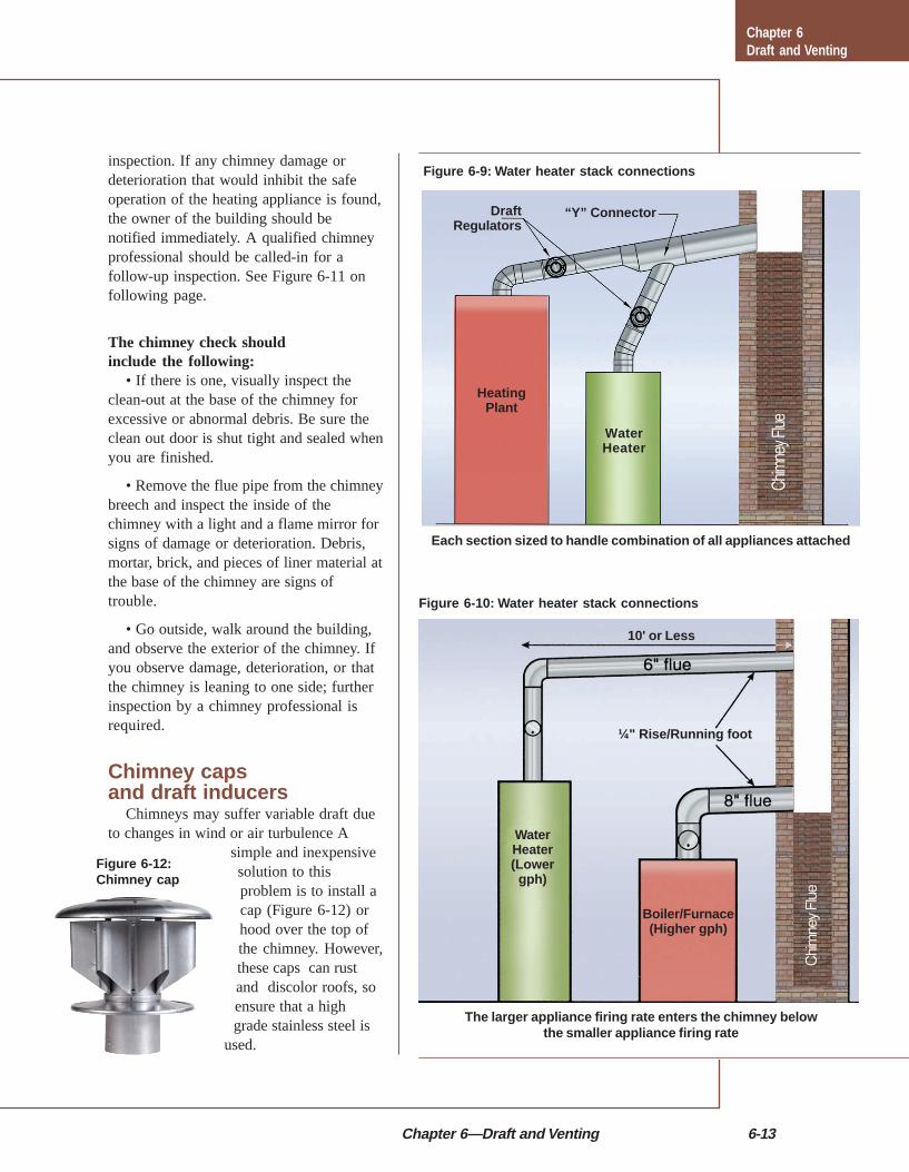
Water heater and furnacestack connections
When an oil-fired water heater isinstalled, it is usually necessary to connectthe flue to the same chimney as the furnace
or boiler. This can be done in two ways:1. The two flue pipes can be joined
together with a Y connector, as shown inFigure 6-9. (‘T’ connectors should NOT beused as they often cause venting problemsfor both appliances.) The exit, or chimneyside of the Y should be at least one sizelarger than the largest flue pipe.
2. If you do not use the Y fitting, youcan make a second opening in the chimney.
If two or more openings are providedinto one chimney flue, they must be atdifferent levels. The flue pipe from the unitwith the lower firing rate should enter atthe highest level consistent with availableheadroom and clearances to combustiblematerial (see Figure 6-10). A separate draftregulator should be installed for eachappliance.
Developments affectingchimneys and exhaust
High efficiency equipment has broughtabout changes that can affect chimneydraft. Some of these developments, such aslower flue gas temperatures, reduced firingrates, and cold start boilers, will reduce thedraft produced by chimneys, and can causeoperational problems.
The most serious consequence oflowered flue gas temperatures is condensa-tion. The water vapor in the combustionproducts can drop below the dew point, andturn into water. Because of the sulfuricoxides present in the gases, this water isacidic. It creates scale in the heat ex-changer, corrodes the flue pipe and attacksthe cement in the chimney. A net flue gastemperature of at least 350°F is recom-mended to avoid this problem. Corrosionresistant chimney liners also help.
Chimney checkThe objective of a chimney check is to
identify obvious and serious chimneyproblems. It is not intended to be a detailed
Chapter 6Draft and Venting
IntakeAir Hood
Draft Control
Outside Wall
VRV-VacuumRelief Valve Field AirBoot® or BigBootTM
Furnace/Boiler
Chapter 6—Draft and Venting 6-13
Figure 6-10: Water heater stack connections
Figure 6-9: Water heater stack connections
Figure 6-12:Chimney cap
inspection. If any chimney damage ordeterioration that would inhibit the safeoperation of the heating appliance is found,the owner of the building should benotified immediately. A qualified chimneyprofessional should be called-in for afollow-up inspection. See Figure 6-11 onfollowing page.
The chimney check shouldinclude the following:
• If there is one, visually inspect theclean-out at the base of the chimney forexcessive or abnormal debris. Be sure theclean out door is shut tight and sealed whenyou are finished.
• Remove the flue pipe from the chimneybreech and inspect the inside of thechimney with a light and a flame mirror forsigns of damage or deterioration. Debris,mortar, brick, and pieces of liner material atthe base of the chimney are signs oftrouble.
• Go outside, walk around the building,and observe the exterior of the chimney. Ifyou observe damage, deterioration, or thatthe chimney is leaning to one side; furtherinspection by a chimney professional isrequired.
Chimney capsand draft inducers
Chimneys may suffer variable draft dueto changes in wind or air turbulence A
simple and inexpensivesolution to thisproblem is to install acap (Figure 6-12) orhood over the top ofthe chimney. However,these caps can rustand discolor roofs, soensure that a highgrade stainless steel is
used.
Chapter 6Draft and Venting
Each section sized to handle combination of all appliances attached
The larger appliance firing rate enters the chimney belowthe smaller appliance firing rate
DraftRegulators
“Y” Connector
HeatingPlant
WaterHeater
WaterHeater(Lower
gph)
Boiler/Furnace(Higher gph)
10' or Less
¼" Rise/Running foot

6-14 Draft and Venting
Figure 6-11: Chimney check
Chapter 6Draft and Venting
Chapter 6—Draft and Venting 6-15
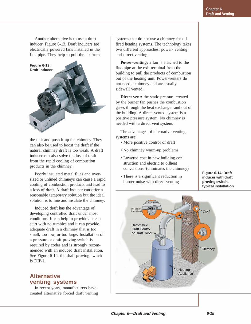
Another alternative is to use a draftinducer, Figure 6-13. Draft inducers areelectrically powered fans installed in theflue pipe. They help to pull the air from
the unit and push it up the chimney. Theycan also be used to boost the draft if thenatural chimney draft is too weak. A draftinducer can also solve the loss of draftfrom the rapid cooling of combustionproducts in the chimney.
Poorly insulated metal flues and over-sized or unlined chimneys can cause a rapidcooling of combustion products and lead toa loss of draft. A draft inducer can offer areasonable temporary solution but the idealsolution is to line and insulate the chimney.
Induced draft has the advantage ofdeveloping controlled draft under mostconditions. It can help to provide a cleanstart with no rumbles and it can provideadequate draft in a chimney that is toosmall, too low, or too large. Installation ofa pressure or draft-proving switch isrequired by codes and is strongly recom-mended with an induced draft installation.See Figure 6-14, the draft proving switchis DIP-1.
Alternativeventing systems
In recent years, manufacturers havecreated alternative forced draft venting
Figure 6-13:Draft inducer
Figure 6-14: Draftinducer with draftproving switch,typical installation
systems that do not use a chimney for oil-fired heating systems. The technology takestwo different approaches: power- ventingand direct-venting.
Power-venting: a fan is attached to theflue pipe at the exit terminal from thebuilding to pull the products of combustionout of the heating unit. Power-venters donot need a chimney and are usuallysidewall vented.
Direct vent: the static pressure createdby the burner fan pushes the combustiongases through the heat exchanger and out ofthe building. A direct-vented system is apositive pressure system. No chimney isneeded with a direct vent system.
The advantages of alternative ventingsystems are:
• More positive control of draft
• No chimney warm-up problems
• Lowered cost in new building construction and electric to oilheatconversions (eliminates the chimney)
• There is a significant reduction inburner noise with direct venting
Chapter 6Draft and Venting

6-16 Draft and Venting
to leave the instructions in an obvious placefor the next technician.
The installation and use of any alterna-tive venting system must not only followthe manufacturers’ instructions, but alsocomply with all local and state buildingcodes. Most of the instructions and codesconform to the following guidelines for thelocation of the exit terminal of the system.See Figure 6-15.
Figure 6-15:Vent hoodlocation
• Eliminate back drafts caused when anearby structure is above the top of thechimney
• Reduction in system standby losses byeliminating off-cycle chimney draft
When installing or servicing either ofthese systems, it is very important that youread and understand the manufacturer’sinstructions. When you are finished, be sure
Recommended Clearances:Exhaust products contain sulfur
which can affect mechanicalequipment, metal objects
and vegetation
Chapter 6Draft and Venting
Vent Hood Location Requirements

Chapter 6—Draft and Venting 6-17
The following guidelinesare often required by code:
• Direct vent systems can be placed onany wall, but if possible they should not belocated on the wall facing the prevailingwind (the prevailing wind generally comesfrom the north and the west; if possible,locate on the south or east side of thebuilding).
• The vent terminal must be at least onefoot above grade level, and three feet awayfrom any inside corner. It may need to behigher in areas with snowfall.
• The vent terminal shall not be less thanthree feet above any forced air inlet intothe building that is located within 10 feetof the terminal.
• The vent terminal shall not be less thanfour feet below, four feet horizontally, orone foot above any door, window, orgravity inlet into any building. The ventshall not be installed in a window well.
• The vent terminal shall not be less thantwo feet from an adjacent building.
• The vent terminal shall not be less thanseven feet above grade whenlocated adjacent to public walk-ways.
• The vent terminal shall belocated so that flue gases are notdirected to jeopardize people,overheat combustible structures ormaterials, or enter buildings.
• All positive pressure joints inthe vent system (all joints indirect-vent, all joints on theexhaust side of the power-venter)are to be sealed with Permatex#81164 high temperature sealer orequivalent to prevent leakage ofthe products of combustion intothe building. We are referringhere to both the joints between
pieces of pipe and the slip joints on elbows.
• The minimum distance to combustiblematerials from any single wall, vent systemcomponent is 18 inches.
• The vent termination should not bemounted directly above or within three feethorizontally from a gas meter, electricmeter or air conditioning condenser.
Power-ventingPower-venting is an economical alterna-
tive to conventional chimney venting.Power-venters use a motor and fan to ventthe products of combustion from theappliance to the outdoors.
Power-venters are designed with the fanlocated either outdoors or indoors justbefore the outside wall, as in Figure 6-16.This insures that combustion gases in theflue pipe are always under negativepressure, so if there are any leaks, air willleak into the pipe and the combustion gaseswill not spill into the building.
The flue gases are discharged through adouble wall vent termination piece and an
Figure 6-16:Powerventer,indoor fan
Chapter 6Draft and Venting
BarometricDamper
3-Wire Conductor(Low Voltage)
Measure DraftHere
Furnace
Power Venter
24 VAC Relay coilApprovedVent Hood
6-18 Draft and Venting
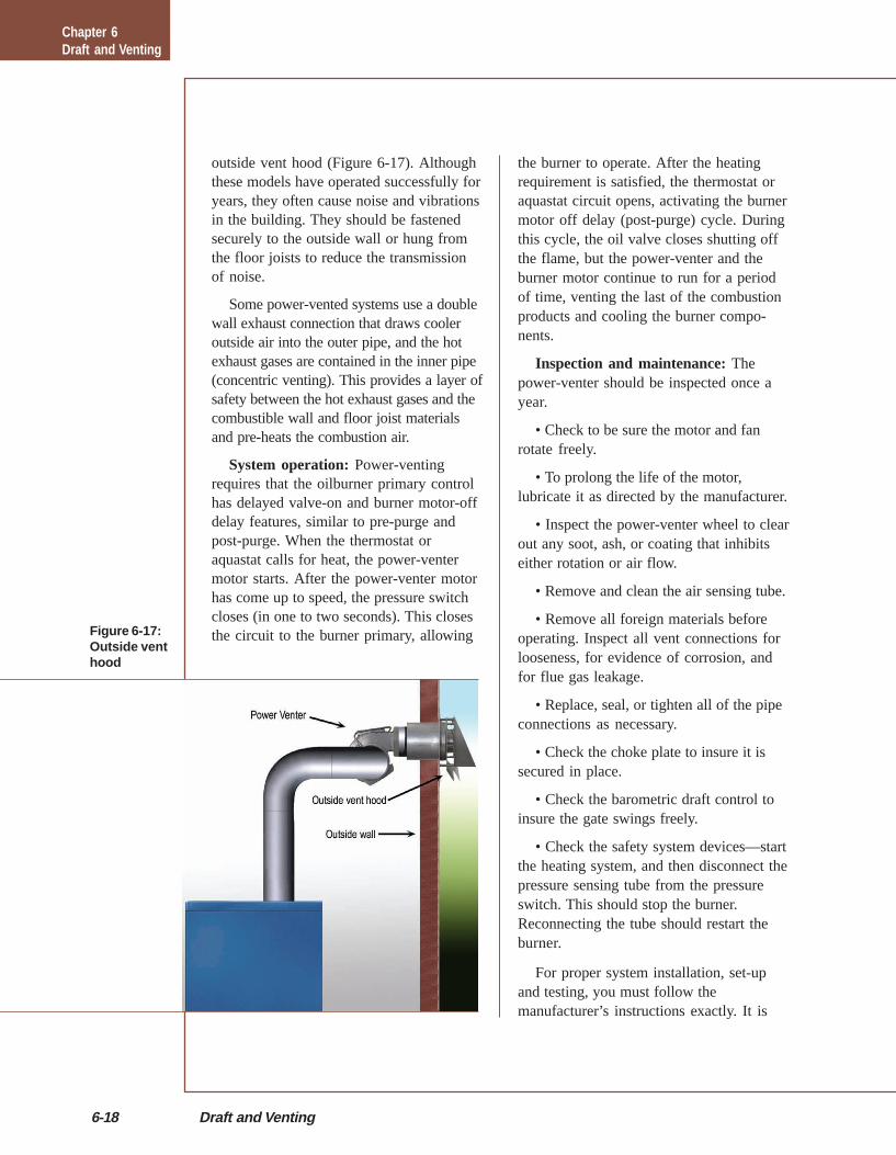
outside vent hood (Figure 6-17). Althoughthese models have operated successfully foryears, they often cause noise and vibrationsin the building. They should be fastenedsecurely to the outside wall or hung fromthe floor joists to reduce the transmissionof noise.
Some power-vented systems use a doublewall exhaust connection that draws cooleroutside air into the outer pipe, and the hotexhaust gases are contained in the inner pipe(concentric venting). This provides a layer ofsafety between the hot exhaust gases and thecombustible wall and floor joist materialsand pre-heats the combustion air.
System operation: Power-ventingrequires that the oilburner primary controlhas delayed valve-on and burner motor-offdelay features, similar to pre-purge andpost-purge. When the thermostat oraquastat calls for heat, the power-ventermotor starts. After the power-venter motorhas come up to speed, the pressure switchcloses (in one to two seconds). This closesthe circuit to the burner primary, allowing
the burner to operate. After the heatingrequirement is satisfied, the thermostat oraquastat circuit opens, activating the burnermotor off delay (post-purge) cycle. Duringthis cycle, the oil valve closes shutting offthe flame, but the power-venter and theburner motor continue to run for a periodof time, venting the last of the combustionproducts and cooling the burner compo-nents.
Inspection and maintenance: Thepower-venter should be inspected once ayear.
• Check to be sure the motor and fanrotate freely.
• To prolong the life of the motor,lubricate it as directed by the manufacturer.
• Inspect the power-venter wheel to clearout any soot, ash, or coating that inhibitseither rotation or air flow.
• Remove and clean the air sensing tube.
• Remove all foreign materials beforeoperating. Inspect all vent connections forlooseness, for evidence of corrosion, andfor flue gas leakage.
• Replace, seal, or tighten all of the pipeconnections as necessary.
• Check the choke plate to insure it issecured in place.
• Check the barometric draft control toinsure the gate swings freely.
• Check the safety system devices—startthe heating system, and then disconnect thepressure sensing tube from the pressureswitch. This should stop the burner.Reconnecting the tube should restart theburner.
For proper system installation, set-upand testing, you must follow themanufacturer’s instructions exactly. It is
Figure 6-17:Outside venthood
Chapter 6Draft and Venting
Chapter 6—Draft and Venting 6-19
also a good idea when installing a power-venter, that you also install a fresh air kit tobring combustion air to the burner fromoutdoors. Many power-venters integrate afresh combustion air intake into theirsystem. If they do not, you should ensurethat the pipes are spaced so that they do notinterfere with each other—at least 12inches apart. Fresh air should be brought infrom the same wall as the power-venterexhaust to equalize air pressure within thevent and intake system.
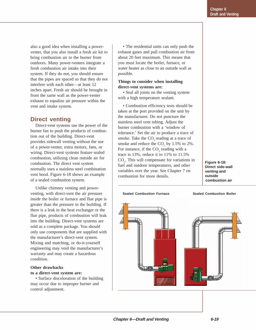
Direct ventingDirect-vent systems use the power of the
burner fan to push the products of combus-tion out of the building. Direct-ventprovides sidewall venting without the useof a power-venter, extra motors, fans, orwiring. Direct-vent systems feature sealedcombustion, utilizing clean outside air forcombustion. The direct vent systemnormally uses a stainless steel combinationvent hood. Figure 6-18 shows an exampleof a sealed combustion system.
Unlike chimney venting and power-venting, with direct-vent the air pressureinside the boiler or furnace and flue pipe isgreater than the pressure in the building. Ifthere is a leak in the heat exchanger or theflue pipe, products of combustion will leakinto the building. Direct-vent systems aresold as a complete package. You shouldonly use components that are supplied withthe manufacturer’s direct-vent system.Mixing and matching, or do-it-yourselfengineering may void the manufacturer’swarranty and may create a hazardouscondition.
Other drawbacksto a direct-vent system are:
• Surface discoloration of the buildingmay occur due to improper burner andcontrol adjustment.
Figure 6-18:Direct side-wallventing andoutsidecombustion air
• The residential units can only push theexhaust gases and pull combustion air fromabout 20 feet maximum. This means thatyou must locate the boiler, furnace, orwater heater as close to an outside wall aspossible.
Things to consider when installingdirect-vent systems are:
• Seal all joints on the venting systemwith a high temperature sealant.
• Combustion efficiency tests should betaken at the port provided on the unit bythe manufacturer. Do not puncture thestainless steel vent tubing. Adjust theburner combustion with a ‘window oftolerance.’ Set the air to produce a trace ofsmoke. Take the CO
2 reading at a trace of
smoke and reduce the CO2 by 1.5% to 2%.
For instance, if the CO2 reading with a
trace is 13%, reduce it to 11% to 11.5%CO
2. This will compensate for variations in
fuel and outdoor temperatures, and othervariables over the year. See Chapter 7 oncombustion for more details.
Chapter 6Draft and Venting
Sealed Combustion Furnace Sealed Combustion Boiler