Readme Supplement Version 6 - sstusa.com · m2 = total cross-sectional area of bolts at root of...
20
Readme Supplement Version 6.80 Disclaimer Please read the following carefully: This software and this document have been developed and checked for correctness and accuracy by SST Systems, Inc. (SST) and InfoPlant Technologies Pvt. Ltd. (InfoPlant). However, no warranty, expressed or implied, is made by SST and InfoPlant as to the accuracy and correctness of this document or the functioning of the software and the accuracy, correctness and utilization of its calculations. Users must carry out all necessary tests to assure the proper functioning of the software and the applicability of its results. All information presented by the software is for review, interpretation, approval and application by a Registered Professional Engineer. CAEPIPE is a trademark of SST and InfoPlant. CAEPIPE Version 6.80, © 2013, SST Systems, Inc. and InfoPlant Technologies Pvt. Ltd. All Rights Reserved. SST Systems, Inc. Tel: (408) 452-8111 1798 Technology Drive, Suite 236 Fax: (408) 452-8388 San Jose, California 95110 Email: [email protected] USA www.sstusa.com InfoPlant Technologies Pvt. Ltd. Tel: +91-80-40336999 7, Crescent Road Fax: +91-80-41494967 Bangalore – 560001 Email: [email protected] India www.infoplantindia.com
Transcript of Readme Supplement Version 6 - sstusa.com · m2 = total cross-sectional area of bolts at root of...

Readme Supplement
Version 6.80 Disclaimer Please read the following carefully:
This software and this document have been developed and checked for correctness and accuracy by SST Systems, Inc. (SST) and InfoPlant Technologies Pvt. Ltd. (InfoPlant). However, no warranty, expressed or implied, is made by SST and InfoPlant as to the accuracy and correctness of this document or the functioning of the software and the accuracy, correctness and utilization of its calculations.
Users must carry out all necessary tests to assure the proper functioning of the software and the applicability of its results. All information presented by the software is for review, interpretation, approval and application by a Registered Professional Engineer.
CAEPIPE is a trademark of SST and InfoPlant.
CAEPIPE Version 6.80, © 2013, SST Systems, Inc. and InfoPlant Technologies Pvt. Ltd. All Rights Reserved.
SST Systems, Inc. Tel: (408) 452-8111 1798 Technology Drive, Suite 236 Fax: (408) 452-8388 San Jose, California 95110 Email: [email protected] USA www.sstusa.com InfoPlant Technologies Pvt. Ltd. Tel: +91-80-40336999 7, Crescent Road Fax: +91-80-41494967 Bangalore – 560001 Email: [email protected] India www.infoplantindia.com

Annexure A
Operating Stress for NDE

Operating Stress for NDE The stress (Sopr) due to operating loads (pressure, weight and thermal load T1) is calculated as
alltbaopr SSSSS 22 )2()(
where
14
Operating
a AF
tPDS
1
22 )()(
Operating
ooiib Z
MiMiS
12
Operating
tt Z
MS
P = maximum of CAEPIPE input pressures P1, P2 and P3
D = outside diameter
t = nominal wall thickness
A un-corroded cross-sectional area of the pipe
F longitudinal force
ii in-plane stress intensification factor according to analysis code selected in CAEPIPE
oi out-of-plane stress intensification factor according to analysis code selected in CAEPIPE
Note: If the analysis code selected provides only the stress intensification I, then ii = io = i.
iM in-plane bending moment
oM out-of-plane bending moment
tM torsional bending moment
Z = un-corroded section modulus; for reduced outlets / branch connections, effective section modulus
)25.025.1( hotcoldall SSfS + hotS
f stress range reduction factor = 6/N0.2
N = Number of equivalent full-range thermal cycles
Scold = basic allowable stress at Tref
Shot = basic allowable stress at CAEPIPE input temperature T1
Annexure B
Flange Stress Calculations
ASME Section VIII Div. 1 – Appendix 2

ASME Section VIII Div. 1 – Appendix 2 Notation The symbols described below are used in the formulas for the design of flanges
A = outside diameter of flange
Ab = cross-sectional area of the bolts using the root diameter of the thread
Am = total required cross-sectional area of bolts taken as greater of Am1 and Am2
Am1 = total cross-sectional area of bolts at root of thread or section of least diameter under stress, required for the operating conditions
=b
m
SW 1
Am2 = total cross-sectional area of bolts at root of thread or section of least diameter under stress
= a
m
SW 2
B = inside diameter of flange
B’ = inside diameter of reverse flange
b = effective gasket or joint-contact-surface seating width
b0 = basic gasket seating width (from Table 2-5.2)
C = bolt-circle diameter
c = basic dimension used for the minimum sizing of welds
e = factor = oh
F
d = factor = 200 gh
VU
for integral type flanges
d = factor = 200 gh
VU
L
for loose type flanges
e = factor = oh
Ffor integral type flanges
e = factor = o
L
hF
for loose type flanges
F = factor for integral type flanges (from Fig. 2-7.2)
FL = factor for loose type flanges (from Fig. 2-7.4)
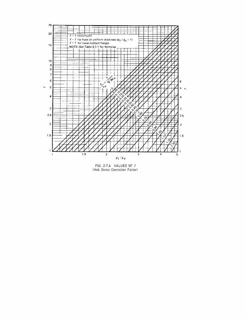
f = hub stress correction for integral flanges from Fig. 2-7.6 (when greater than one, this is the ratio of the stress in the small end of hub to the stress in the large end.) (for values below limit of figure, use f = 1.)
G = diameter at location of gasket load reaction
g0 = thickness of hub at small end
g1 = thickness of hub at back of flange
H = total hydrostatic end force = PG 2785.0
HD = hydrostatic end force on area inside of flange = PB 2785.0
HG = gasket load (difference between flange design bolt load and total hydrostatic end force) = W – H
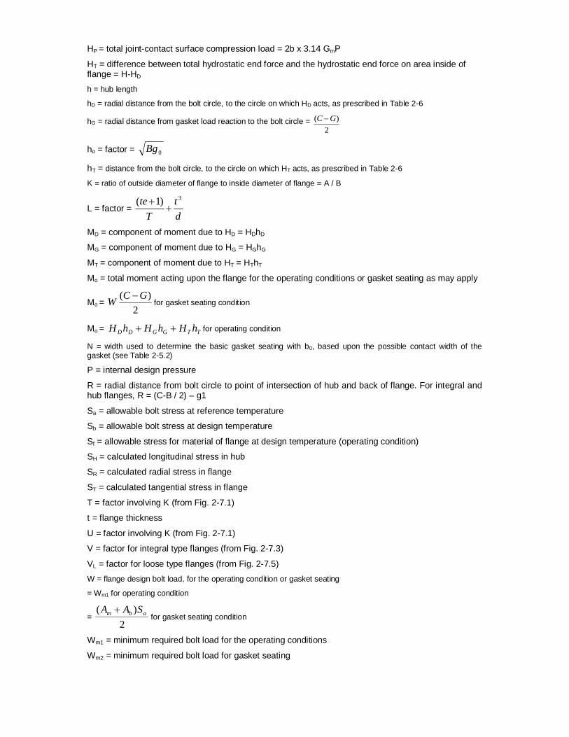
HP = total joint-contact surface compression load = 2b x 3.14 GmP
HT = difference between total hydrostatic end force and the hydrostatic end force on area inside of flange = H-HD
h = hub length
hD = radial distance from the bolt circle, to the circle on which HD acts, as prescribed in Table 2-6
hG = radial distance from gasket load reaction to the bolt circle = 2
)( GC
ho = factor = 0Bg
hT = distance from the bolt circle, to the circle on which HT acts, as prescribed in Table 2-6
K = ratio of outside diameter of flange to inside diameter of flange = A / B
L = factor = dt
Tte 3)1(
MD = component of moment due to HD = HDhD
MG = component of moment due to HG = HGhG
MT = component of moment due to HT = HThT
Mo = total moment acting upon the flange for the operating conditions or gasket seating as may apply
Mo = 2
)( GCW for gasket seating condition
Mo = TTGGDD hHhHhH for operating condition
N = width used to determine the basic gasket seating with b0, based upon the possible contact width of the gasket (see Table 2-5.2)
P = internal design pressure
R = radial distance from bolt circle to point of intersection of hub and back of flange. For integral and hub flanges, R = (C-B / 2) – g1
Sa = allowable bolt stress at reference temperature
Sb = allowable bolt stress at design temperature
Sf = allowable stress for material of flange at design temperature (operating condition)
SH = calculated longitudinal stress in hub
SR = calculated radial stress in flange
ST = calculated tangential stress in flange
T = factor involving K (from Fig. 2-7.1)
t = flange thickness
U = factor involving K (from Fig. 2-7.1)
V = factor for integral type flanges (from Fig. 2-7.3)
VL = factor for loose type flanges (from Fig. 2-7.5)
W = flange design bolt load, for the operating condition or gasket seating
= Wm1 for operating condition
= 2
)( abm SAA for gasket seating condition
Wm1 = minimum required bolt load for the operating conditions
Wm2 = minimum required bolt load for gasket seating

w = width used to determine the basic gasket seating width b0, based upon the contact width between the flange and the gasket (see Table 2-5.2)
Y = factor involving K (from Fig. 2-7.1)
y = gasket or joint-contact-surface unit seating load
Z = factor involving K (from Fig. 2-7.1)
Calculation of Flange Stresses The stresses in the flange shall be determined for both the operating conditions and gasket seating condition, in accordance with the following formulas:
(1) Integral type flanges
Longitudinal hub stress fO
H SBLg
fMS 5.121
Radial flange stress f
OR S
BLtMteS
2
)133.1(
Tangential flange stress fRO
T SZSBt
YMS 2
Combined stress
fRH SSS
2
and
fTH SSS
2
(2) Loose type flanges with hubs
Longitudinal hub stress f
OH S
BLgfM
S 5.121
Radial flange stress f
OR S
BLtMteS
2
)133.1(
Tangential flange stress fR
OT SZS
BtYMS 2
Combined stress
fRH SSS
2
and
fTH SSS
2
where,
L = factor = dt
Tte 3)1(
d = factor = 200 gh
VU
L
e = factor = o
L
hF
VL = factor for loose type flanges (from Fig. 2-7.5)

FL = factor for loose type flanges (from Fig. 2-7.4)
(3) Loose type flanges without hubs
Longitudinal hub stress HS 0
Radial flange stress RS 0
Tangential flange stress fO
T SBt
YMS 2
Combined stress
fRH SSS
2
and
fTH SSS
2
where,
L = factor = dt
Tte 3)1(
d = factor = 200 gh
VU
L
e = factor = o
L
hF
VL = factor for loose type flanges (from Fig. 2-7.5)
FL = factor for loose type flanges (from Fig. 2-7.4)
(4) Optional type flanges (calculated as loose flanges without hubs)
Longitudinal hub stress HS 0
Radial flange stress RS 0
Tangential flange stress fO
T SBt
YMS 2
Combined stress
fRH SSS
2
and
fTH SSS
2
where,
L = factor = dt
Tte 3)1(
d = factor = 200 gh
VU
L
e = factor = o
L
hF
VL = factor for loose type flanges (from Fig. 2-7.5)

FL = factor for loose type flanges (from Fig. 2-7.4)
(5) Reverse type flanges
Longitudinal hub stress fr
OH S
BgLfMS 5.1
'21
Radial flange stress fr
OrR S
BtLMteS
')133.1(
2
Tangential flange stress fr
rR
OrT S
teteZS
BtMYS
133.1167.0
2
Combined stress
fRH SSS
2
and
fTH SSS
2
where,
Lr = factor = r
r
dt
Tte 3)1(
dr = factor = 200 gh
VU r
er = factor = oh
F
ho = factor = 0Ag
2
)1(668.01
KY
K
r
Tr = TZZ
r3.03.0
Ur = Ur
Yr = Yr


Verification and Validation Problem 1: (Example on page 19 Chapter 40 “Bolted-Flange Joints and Connections” by William J. Koves on “Companion Guide to the ASME Boiler & Pressure Vessel Code” by K .R. Rao [2001], American Society of Mechanical Engineers, U.S.)
Flange Details: Flange Type : Integral Flanges Flange Outside Diameter [A] = 39.125 (inch) Flange Inside Diameter [B] = 32 (inch) Flange Thickness [t] = 2 (inch) Small End Hub Thickness [g0] = 0.5 (inch) Large End Hub Thickness [g1] = 1.125 (inch) Hub Length [h] = 2.75 (inch) All. Stress @ Design Temp [sf] = 19600 (psi) All. Stress @ Ref. Temp [sfa] = 20000 (psi) Modulus @ Design Temp [E] = 2.7E+7 (psi) Modulus @ Ref. Temp [Ea] = 2.92E+7 (psi) Bolting Information: Bolt Circle Diameter = 37 (inch) Number of Bolts = 36 Bolt Diameter = 1 (inch) All. Stress @ Ref. Temp [sa] = 25000 (psi) All. Stress @ Design Temp [sb] = 25000 (psi) Gasket Information: Gasket Outside Diameter = 35.5 (inch) Gasket Inner Diameter = 33.5 (inch) Leak Pressure Ratio [m] = 3.00 Gasket Seating Stress [y] = 10000 (psi) Facing Sketch = 1 Facing Column = 1 Load Data: Design Pressure = 414 (psi) Design Temperature = 500 (F) Axial Force = 1000 (lb) Bending Moment = 200 (ft-lb) Allowable Pressure = 665 (psi)
Comparison of Results: Flange Stresses Text Book Results
(psi) CAEPIPE
(psi) CAESAR II
(psi) Operating condition Longitudinal Hub (SH) 24150 24152 24227 Radial Flange (SR) 11590 11590 11636 Tangential Flange (ST) 7230 7232 7205 0.5(SH + SR) 17870 17871 17932 0.5(SH + ST) 15690 15692 15716 Gasket Seating Condition Longitudinal Hub (SH) 15270 15269 15292 Radial Flange (SR) 7330 7327 7345 Tangential Flange (ST) 4570 4572 4547 0.5(SH + SR) 11300 11298 11318 0.5(SH + ST) 9900 9921 9920

Problem 2: (Example from “Taylor Forge & Pipe Works, 1961”) Flange Details: Flange Type : Loose Flanges with Hubs Flange Outside Diameter [A] = 40.375 (inch) Flange Inside Diameter [B] = 33.25 (inch) Inside Diameter of Reverse Flange [B'] = 20 (inch) Flange Thickness [t] = 2.125 (inch) Small End Hub Thickness [g0] = 0.875 (inch) Large End Hub Thickness [g1] = 1.125 (inch) Hub Length [h] = 2.5 (inch) All. Stress @ Design Temp [sf] = 17500 (psi) All. Stress @ Ref. Temp [sfa] = 17500 (psi) Modulus @ Design Temp [E] = 2.7E+7 (psi) Modulus @ Ref. Temp [Ea] = 2.92E+7 (psi) Bolting Information: Bolt Circle Diameter = 38.25 (inch) Number of Bolts = 44 Bolt Diameter = 1 (inch) All. Stress @ Ref. Temp [sa] = 20000 (psi) All. Stress @ Design Temp [sb] = 20000 (psi) Gasket Information: Gasket Outside Diameter = 35.75 (inch) Gasket Inner Diameter = 34.25 (inch) Leak Pressure Ratio [m] = 2.75 Gasket Seating Stress [y] = 3700 (psi) Facing Sketch = 1 Facing Column = 1 Load Data: Design Pressure = 400 (psi) Design Temperature = 500 (F) Axial Force = 1000 (lb) Bending Moment = 200 (ft-lb) Allowable Pressure = 665 (psi) Comparison of Results:
Flange Stresses Text Book Results (psi)
CAEPIPE (psi)
CAESAR II (psi)
Operating condition Longitudinal Hub (SH) 20800 21153 21214 Radial Flange (SR) 11100 11110 11155 Tangential Flange (ST) 13800 13826 13797 0.5(SH + SR) 15950 16132 16185 0.5(SH + ST) 17300 17489 17506 Gasket Seating Condition Longitudinal Hub (SH) 14400 14623 15095 Radial Flange (SR) 7660 7681 7938 Tangential Flange (ST) 9500 9558 9818 0.5(SH + SR) 11030 11152 11517 0.5(SH + ST) 11950 12091 12457

Problem 3:
(Example 10.5 on page 209 Chapter 10 on “CASTI Guidebook to ASME Section VIII Div.1 – Pressure Vessels – Third Edition”) Flange Details: Flange Type : Reverse Flanges Flange Outside Diameter [A] = 49 (inch) Flange Inside Diameter [B] = 48.25 (inch) Inside Diameter of Reverse Flange [B'] = 20.25 (inch) Flange Thickness [t] = 5.25 (inch) Small End Hub Thickness [g0] = 0.375 (inch) Large End Hub Thickness [g1] = 1.375 (inch) Hub Length [h] = 6 (inch) All. Stress @ Design Temp [sf] = 12000 (psi) All. Stress @ Ref. Temp [sfa] = 20000 (psi) Modulus @ Design Temp [E] = 2.7E+7 (psi) Modulus @ Ref. Temp [Ea] = 2.92E+7 (psi) Bolting Information: Bolt Circle Diameter = 44 (inch) Number of Bolts = 32 Bolt Diameter = 1.25 (inch) All. Stress @ Ref. Temp [sa] = 25000 (psi) All. Stress @ Design Temp [sb] = 21000 (psi) Gasket Information: Gasket Outside Diameter = 24 (inch) Gasket Inner Diameter = 22 (inch) Leak Pressure Ratio [m] = 2.50 Gasket Seating Stress [y] = 10000 (psi) Facing Sketch = 1 Facing Column = 1 Load Data: Design Pressure = 150 (psi) Design Temperature = 800 (F) Axial Force = 1000 (lb) Bending Moment = 200 (ft-lb) Allowable Pressure = 665 (psi) Comparison of Results:
Flange Stresses Text Book Results (psi)
CAEPIPE (psi)
CAESAR II (psi)
Operating condition Longitudinal Hub (SH) 2060 2257 2055 Radial Flange (SR) 280 307 280 Tangential Flange (ST) 1340 1314 1336 0.5(SH + SR) 1170 1282 1168 0.5(SH + ST) 1700 1785 1695 Gasket Seating Condition Longitudinal Hub (SH) 9220 10082 9220 Radial Flange (SR) 1260 1372 1257 Tangential Flange (ST) 6000 7004 5997 0.5(SH + SR) 5240 5727 5239 0.5(SH + ST) 7610 8543 8703

Problem 4: (Example from KEDKEP CONSULTING, INC. dated May 27, 2008) Flange Details:
Flange Type : Loose Flanges without Hubs / Optional Flanges Flange Outside Diameter [A] = 38.4 (inch) Flange Inside Diameter [B] = 32 (inch) Inside Diameter of Reverse Flange [B'] = 32 (inch) Flange Thickness [t] = 4 (inch) Small End Hub Thickness [g0] = 0.001 (inch) Large End Hub Thickness [g1] = 0.001 (inch) Hub Length [h] = 0.001 (inch) All. Stress @ Design Temp [sf] = 20000 (psi) All. Stress @ Ref. Temp [sfa] = 20000 (psi) Modulus @ Design Temp [E] = 2.7E+7 (psi) Modulus @ Ref. Temp [Ea] = 2.92E+7 (psi)
Bolting Information: Bolt Circle Diameter = 36 (inch) Number of Bolts = 28 Bolt Diameter = 1 (inch) All. Stress @ Ref. Temp [sa] = 25000 (psi) All. Stress @ Design Temp [sb] = 25000 (psi)
Gasket Information: Gasket Outside Diameter = 32.75 (inch) Gasket Inner Diameter = 32 (inch) Leak Pressure Ratio [m] = 0.50 Gasket Seating Stress [y] = 0 (psi) Facing Sketch = 2 Facing Column = 2
Load Data: Design Pressure = 300 (psi) Design Temperature = 295 (F) Axial Force = 1000 (lb) Bending Moment = 200 (ft-lb) Allowable Pressure = 665 (psi)
Comparison of Results: Flange Stresses Text Book Results
(psi) CAEPIPE
(psi) CAESAR II
(psi) Operating Condition Longitudinal Hub (SH) 0 0 3 Radial Flange (SR) 0 0 0 Tangential Flange (ST) 10577 10569 10618 0.5(SH + SR) 0 0 1.5 0.5(SH + ST) 0 0 5310.5 Bolt Stress 16378 16371 16445 Gasket Seating Conditon Longitudinal Hub (SH) 0 0 3 Radial Flange (SR) 0 0 0 Tangential Flange (ST) 12147 11987 12166 0.5(SH + SR) 0 0 1.5 0.5(SH + ST) 0 0 6085 Bolt Stress 0 0 124