READ, UNDERSTAND AND FOLLOW ALL INSTRUCTIONS IN THIS ...
12
Do not pump gasoline or other explosive liquids. Do not operate pump where flammable or explosive fumes or gases are present as a fire or explosion could result. Pump should only be used to pump clear water. Do not run pump dry. 1. Read all manuals included with this product carefully. Be thoroughly familiar with the controls and the proper use of the equipment. 2. Protect electrical cord from sharp objects, hot surfaces, oil and chemicals. Avoid kinking the cord and replace damaged cords immediately. This pump has been evaluated for use with water only. INSTALLATION Models PC1 and PC2 include a six foot long suction hose, a water suction attachment, and a replacement parts kit which includes: impeller, gasket, shaft seal, and two motor brushes (PC2 only, brushes are not designed to be replaced on PC1). Always disconnect power source before attempting to install, service, or maintain the pump. Never handle a pump with wet hands or when standing on wet or damp surface or in water. Fatal electrical shock could occur. 1. A ground fault circuit interrupter (GFCI) is required for Model PC2. Risk of electrical shock! This pump is supplied with a grounding conductor and grounding type attachment plug. A grounded receptacle in conformance with current NEC and local codes must be used (See Figure 1). Do not use model PC2, 115 V Transfer Pump in swimming pool areas. 2. Model PC1 operates on 12V DC only. Model PC2 operates on 115V only. Voltage and current of power supply must match the requirements of the pump. Model PC1 has color-coded battery clamps for 12V operation. Model PC1 requires 14 amps at 12 VDC. 3. Never use an extension cord to power this unit. Risk of fatal electrical shock. Never cut off the round grounding prong. Cutting the cord or plug will void the warranty and make the pump inoperable. 4. Use a strainer when pumping from a creek, pond, or source where foreign objects may be sucked into the pump. The strainer should prevent solids from entering the inlet line. 5. A regular garden hose may be used as a discharge line. 6. The inlet or suction hose should not be longer than 15 feet; and the vertical distance between the pump and the water level should not be any higher than 10 feet. The maximum discharge height is 30 feet. 7. At times, an overload due to overheating, low voltage, jammed impeller, etc. may shut the pump off. Unplug or turn off the pump PC1 and PC2 Series Self-Priming Transfer Pumps OPERATING INSTRUCTIONS & PARTS MANUAL READ, UNDERSTAND AND FOLLOW ALL INSTRUCTIONS IN THIS MANUAL - DO NOT DISCARD. Failure to follow these instructions could result in property damage, serious injury or death. For parts, product & service information visit www.waynepumps.com REMINDER: Keep your dated proof of purchase for warranty purposes! Attach it to this manual or file it for safekeeping. © 2016, WAYNE/Scott Fetzer Company. 1 DESCRIPTION These self-priming transfer pumps are designed to easily transfer water from one point to another. Model PC1, 12 Volt Transfer Pump is convenient when normal power is not readily available. Typical applications include removing water from pool covers, clogged drains, stock tanks, water basins, boats, cisterns, etc. Model PC2, 115 Volt Transfer Pump is great for household usage. Typical applications include removing water from waterbeds, clogged sinks, basements, etc. Note: Do NOT use PC2 in pool areas. The motors on both models PC1 and PC2 are non-submersible. UNPACKING After unpacking the transfer pump, carefully inspect for any damage that may have occurred during transit. Check for loose, missing or damaged parts. SAFETY GUIDELINES To help recognize this information, observe the following signal words/ hazard classifications. DANGER indicates an imminently hazardous situation which, if NOT avoided, WILL result in death or serious injury. WARNING indicates a potentially hazardous situation which, if NOT avoided, COULD result in death or serious injury. CAUTION indicates a potentially hazardous situation which, if NOT avoided, MAY result in minor or moderate injury. NOTICE indicates important information, that if NOT followed, MAY cause damage to equipment. This is the safety alert symbol. It is used to alert you to potential bodily injury hazards. Obey all safety messages that follow this symbol to avoid possible harm. NOTE: Information that requires special attention. GENERAL SAFETY INFORMATION CALIFORNIA PROPOSITION 65 This product contains chemicals known to the state of California to cause cancer or birth defects or other reproductive harm. California’s Proposition 65 requires this warning to be given to customers in the state of California. GENERAL SAFETY Do not submerge motor or allow motor to be exposed to water. Personal injury and/or death could result. Keep pump and power cords away from liquids. Model PC1 becomes very hot during operation. 321209-001 4/16
Transcript of READ, UNDERSTAND AND FOLLOW ALL INSTRUCTIONS IN THIS ...

Do not pump gasoline or other explosive liquids. Do not operate
pump where flammable or explosive fumes or gases are present as a fire or explosion could result. Pump should only be used to pump clear water. Do not run pump dry.1. Read all manuals included with this product carefully. Be
thoroughly familiar with the controls and the proper use of the equipment.
2. Protect electrical cord from sharp objects, hot surfaces, oil and chemicals. Avoid kinking the cord and replace damaged cords immediately.
This pump has been evaluated for use with water only.
INSTALLATIONModels PC1 and PC2 include a six foot long suction hose, a water suction attachment, and a replacement parts kit which includes: impeller, gasket, shaft seal, and two motor brushes (PC2 only, brushes are not designed to be replaced on PC1). Always disconnect power source before
attempting to install, service, or maintain the pump. Never handle a pump with wet hands or when standing on wet or damp surface or in water. Fatal electrical shock could occur.1. A ground fault circuit interrupter (GFCI) is required for Model PC2. Risk of electrical shock! This pump is supplied
with a grounding conductor and grounding type attachment plug. A grounded receptacle in conformance with current NEC and local codes must be used (See Figure 1). Do not use model PC2, 115 V Transfer Pump in swimming pool areas. 2. Model PC1 operates on 12V DC only. Model PC2 operates on
115V only. Voltage and current of power supply must match the requirements of the pump. Model PC1 has color-coded battery clamps for 12V operation. Model PC1 requires 14 amps at 12 VDC.
3. Never use an extension cord to power this unit. Risk of fatal electrical shock. Never cut off the
round grounding prong. Cutting the cord or plug will void the warranty and make the pump inoperable.4. Use a strainer when pumping from a creek, pond, or source where
foreign objects may be sucked into the pump. The strainer should prevent solids from entering the inlet line.
5. A regular garden hose may be used as a discharge line.6. The inlet or suction hose should not be longer than 15 feet; and the
vertical distance between the pump and the water level should not be any higher than 10 feet. The maximum discharge height is 30 feet.
7. At times, an overload due to overheating, low voltage, jammed impeller, etc. may shut the pump off. Unplug or turn off the pump
PC1 and PC2 Series
Self-Priming Transfer PumpsOPERATING INSTRUCTIONS & PARTS MANUAL
READ, UNDERSTAND AND FOLLOW ALL INSTRUCTIONS IN THIS MANUAL - DO NOT DISCARD. Failure to follow these instructions could result in property damage, serious injury or death.
For parts, product & service information visit www.waynepumps.com
REMINDER: Keep your dated proof of purchase for warranty purposes! Attach it to this manual or file it for safekeeping.
© 2016, WAYNE/Scott Fetzer Company. 1
DESCRIPTIONThese self-priming transfer pumps are designed to easily transfer water from one point to another. Model PC1, 12 Volt Transfer Pump is convenient when normal power is not readily available. Typical applications include removing water from pool covers, clogged drains, stock tanks, water basins, boats, cisterns, etc. Model PC2, 115 Volt Transfer Pump is great for household usage. Typical applications include removing water from waterbeds, clogged sinks, basements, etc. Note: Do NOT use PC2 in pool areas. The motors on both models PC1 and PC2 are non-submersible.
UNPACKINGAfter unpacking the transfer pump, carefully inspect for any damage that may have occurred during transit. Check for loose, missing or damaged parts.
SAFETY GUIDELINESTo help recognize this information, observe the following signal words/hazard classifications. DANGER indicates an imminently hazardous
situation which, if NOT avoided, WILL result in death or serious injury. WARNING indicates a potentially hazardous
situation which, if NOT avoided, COULD result in death or serious injury. CAUTION indicates a potentially hazardous
situation which, if NOT avoided, MAY result in minor or moderate injury. NOTICE indicates important information, that if
NOT followed, MAY cause damage to equipment.This is the safety alert symbol. It is used to alert you to potential bodily injury hazards. Obey all safety messages that follow this symbol to avoid possible harm.
NOTE: Information that requires special attention.
GENERAL SAFETY INFORMATIONCALIFORNIA PROPOSITION 65 This product contains chemicals known to the
state of California to cause cancer or birth defects or other reproductive harm. California’s Proposition 65 requires this warning to be given to customers in the state of California.
GENERAL SAFETY Do not submerge motor or allow motor to be
exposed to water. Personal injury and/or death could result. Keep pump and power cords away from liquids. Model PC1 becomes very hot during operation.
321209-001 4/16

2
www.waynepumps.com
Operating Instructions and Parts Manual
INSTALLATION (CONTINUED) and wait at least ten minutes. The pump will cool and automatically
reset. (Model PC2 only)8. Motor should never be operated for more than 2 hours continuously.
Critical heating can occur and might severely damage the pump and void warranty.
OPERATION1. Add 1 tablespoon of vegetable oil to both inlet and outlet to prime.
Attach included 6 foot suction hose to inlet of pump. Attach garden hose to outlet of pump. There must be a gasket in place to insure that these connections are airtight, otherwise the pump will not prime.
2. Connect water suction attachment to the open end of inlet hose and place below water surface. (Water suction attachment is optional for both PC1 and PC2 models.) The water suction attachment is designed to fit the male end of a garden hose. Place the water suction attachment as near as possible to the middle of the water that is to be pumped.
3. Examine the inlet and outlet hoses to insure there are no blockages, kinks or bends.
Place switch in “OFF” position before connecting or disconnecting battery terminal
clamps.4. Connect pump to power source, with pump in a dry location.
Model PC1: Motor must be connected to a fully charged automotive tractor or marine type battery to operate.
Connect the red clamp to the positive (+) type battery terminal. Connect the black clamp to the negative (-) type battery terminal. See 12V wiring diagram below (Figure 2). Model PC2: Plug into a 115 Volt AC 3-prong ground-type GFCI receptacle.
IMPORTANT BATTERY INFORMATIONBe certain that the area around the batteries is well ventilated. Before servicing the batteries, blow away gasses by waving a piece of cardboard near the batteries. Dangerous hydrogen gas can be released
from batteries while charging. Sparks can ignite the gas in an enclosed space. Wear safety goggles when connecting batteries. Battery connections should be made in a well-ventilated area.
Working in the vicinity of lead acid batteries can be dangerous. Before making
connections or servicing the batteries, read and follow instructions in all applicable instruction manuals. To reduce the risk of battery explosion, follow the instructions in this manual and those published by the battery manufacturer, as well as those of any other equipment used in the surrounding area.
An assistant should be present or close enough to come to your aid in the event of an emergency. Have a reliable source of fresh water and soap nearby in case battery acid contacts clothing, skin or eyes.
Wear eye and clothing protection when working around lead acid batteries.
Avoid touching your eyes when working around lead acid batteries. If battery acid contacts your eye(s), flush
with cold running water for 20 minutes and seek immediate medical attention. If acid contacts your skin or clothing, wash immediately with soap and water.
Never smoke or allow a spark or flame in the vicinity of the battery.
Avoid dropping metal tools on the battery posts because they may spark or short-
circuit the system or battery, causing an explosion.

3
www.waynepumps.com
PC1 and PC2 Series
MAINTENANCE Always disconnect power source before
attempting to install, service, or maintain the pump.
TEST RESET
Figure 1
GROUNDING PLUG
IMPELLER REPLACEMENTThese parts are designed to handle most clear, nonflammable liquids with slight amounts of abrasives. When impeller vanes become worn from use, or damaged due to pumping abrasive liquids or trash, pump performance will be reduced or prevented altogether. 1. Remove the four cover plate screws holding motor housing and
pump housing together. Cover plate is now free and can be removed.
2. Inspect gasket and impeller for wear and damage. If there is any evidence of wear or damage, replace the part(s).
3. Lubricate new impeller with white grease or lightweight oil and reinstall by aligning flat on impeller hub with flat on motor shaft.
4. Reassemble gasket, cover plate, and cover plate screws.
SHAFT SEAL REPLACEMENTMotor shafts are sealed with factory pre-lubricated lip-type seals which are good for the life of the pump. If the seal leaks, it is usually because the pump has handled abrasive liquids. If the motor shaft is scored (deep grooves), the complete pump must be replaced. 1. Remove and inspect impeller parts as specified in the impeller
replacement instructions. Replace worn parts. 2. Remove two pump body mounting screws and slide pump body
from motor. Pry out seal retaining ring and push worn shaft seal from inside of pump body.
3. Lubricate new seal with lightweight oil, push it into pump body with lip facing away from motor, and push in seal retaining ring.
4. Reassemble pump body onto motor with mounting screws. Follow steps 3 and 4 in Impeller Replacement.
12 VOLT WIRING DIAGRAM
RED CLAMPTO POSITIVETERMINAL
BLACK CLAMPTO NEGATIVETERMINAL
POS+
12 VOLT DCBATTERY
-NEG
12 VOLT DC PUMP
INLETOUTLET
Figure 2
MOTOR BRUSH REPLACEMENT PC1 Model is equipped with lifetime brushes.
Brush replacement is not necessary. Brushes for the PC2 pump should be
inspected after 75 hours of operation and replace if worn. They must be replaced every 100 hours of operation. Service one brush at a time.1. Disconnect pump from power supply.2. Remove brush caps with screwdriver.3. Remove old brush assembly.4. Insert new brush assembly.5. Replace brush caps.

4
www.waynepumps.com
Operating Instructions and Parts Manual
TROUBLESHOOTING CHART
Symptom Possible Cause(s) Corrective ActionPump will not start or run 1. Blown fuse 1. If blown, replace with proper sized fuse or reset
breaker
2. Low line voltage 2. Voltage of power supply must match the voltage of the pump
3. Worn brushes 3. Replace brushes (PC2 Only)
4. Impeller blocked 4. Remove blockage
5. Motor has overheated (Model PC2 only) 5. Disconnect from power supply and allow to cool (Minimum 10 minutes)
Pump will not prime or retain prime after operating
1. Air leak in suction line 1. Repair suction line by tightening inlet connection or replace
2. Impeller blocked 2. Remove blockage
3. Worn seal 3. Replace seal
4. Suction lift too high 4. Lower pump
5. Hose kinked or looped 5. Straighten hose
6. Fittings not tight 6. Tighten fittings
7. Suction hose out of water 7. Submerge suction hose end
8. Clogged inlet 8. Clean inlet
Flow rate is too low 1. Inlet hose plugged or kinked 1. Clean or replace
2. Low line voltage 2. Voltage of power supply must match the voltage of the pump
Shaft seal leaks 1. Worn seal 1. Replace seal
2. Shaft grooved 2. Replace pump
3. Pump head loose on motor 3. Insure proper assembly and no obstruction, tighten bolts

5
www.waynepumps.com
PC1 and PC2 Series
For Replacement Parts or Technical Assistance, call 1-800-237-0987Please provide following information:
- Model number- Serial number (if any)- Part description and number as shown in parts list
Address parts correspondence to:Wayne Water Systems101 Production DriveHarrison, OH 45030 U.S.A.
Figure 3 – Replacement Parts Illustration for Self-Priming Transfer Pumps
BATTERY TERMINALCLAMPS
12 VOLT POWER CORD POWER SWITCH
ON/OFF
BRUSH CAP
BRUSH ASSEMBLY(PC2 ONLY)
GROUNDING PLUG
SHAFT
ROTATION
RETAINING RING
SHAFT SEAL
IMPELLER
COVER PLATE
GASKET
WATER SUCTION ATTACHMENT

6
www.waynepumps.com
Operating Instructions and Parts Manual
Limited WarrantyFor one year from the date of purchase, Wayne Water Systems (“Wayne”) will repair or re place, at its option, for the original purchaser any part or parts of its Sump Pumps or Water Pumps (“Product”) found upon examination by Wayne to be defective in materials or work man ship. Please call Wayne (800-237-0987) for instructions or see your dealer. Be pre pared to provide the model and serial number when exercising this warranty. All trans por ta-tion charges on Products or parts submitted for repair or replacement must be paid by purchaser.This Limited Warranty does not cover Products which have been damaged as a result of accident, abuse, misuse, neglect, improper installation, improper main te nance, or failure to operate in accordance with Wayne’s written instructions.THERE IS NO OTHER EXPRESS WARRANTY. IM PLIED WARRANTIES, IN CLUD ING THOSE OF MER CHANT ABIL I TY AND FITNESS FOR A PARTICULAR PUR POSE, ARE LIMITED TO ONE YEAR FROM THE DATE OF PUR CHASE. THIS IS THE EXCLUSIVE REM E DY AND ANY LIABILITY FOR ANY AND ALL IN DI RECT OR CON SE QUEN TIAL DAM AG ES OR EX PENS ES WHATSOEVER IS EXCLUDED.Some states do not allow limitations on how long an implied warranty lasts, or do not allow the exclusions or limitations of incidental or consequential damages, so the above lim i ta tions might not apply to you. This limited war ran ty gives you specific legal rights, and you may also have other legal rights which vary from state to state.In no event, whether as a result of breach of contract warranty, tort (in clud ing negligence) or otherwise, shall Wayne or its suppliers be liable for any special, consequential, incidental or penal damages including, but not limited to loss of profit or revenues, loss of use of the products or any associated equipment, damage to associated equip ment, cost of capital, cost of substitute products, facilities, services or replacement power, downtime costs, or claims of buyer’s cus tom ers for such damages.You MUST retain your purchase receipt along with this form. In the event you need to exercise a warranty claim, you MUST send a copy of the purchase receipt along with the material or correspondence. Please call Wayne (800-237-0987) for return authorization and instructions.
DO NOT MAIL THIS FORM TO WAYNE. Use this form only to maintain your records.
MODEL NO._________________ SERIAL NO.____________________________ INSTALLATION DATE_______________
ATTACH YOUR RECEIPT HERE
lesiones corporales y/o la muerte. Mantenga la bomba y los cables de corriente lejos de los líquidos. El Modelo PC1 se calienta mucho durante el funcionamiento. No bombee gasolina ni otros
líquidos explosivos. No haga funcionar la bomba en presencia de gases o vapores inflamables o explosivos ya que podría provocar un incendio o una explosión. La bomba sólo debe usarse para bombear agua limpia. No haga funcionar la bomba sin líquido.1. Lea atentamente todos los manuales incluidos con este
producto. Familiarícese bien con los controles y el uso correcto del equipo.
2. Proteja el cable de corriente de objetos punzantes, superficies calientes, aceite y productos químicos. Evite doblar el cable y reemplace los cables dañados de inmediato.
Esta bomba fue evaluada para ser usada únicamente con agua.
INSTALACIÓNLos modelos PC1 y PC2 incluyen una manguera de succión de seis pies de largo, un accesorio para succión de agua y un kit de piezas de reemplazo que incluye: impulsor, empaque, sello de eje y dos escobillas de motor (únicamente PC2, en la PC1 las escobillas no están diseñadas para reemplazarse). Siempre desconecte la fuente de energía
antes de intentar instalar o realizar un servicio o mantenimiento de la bomba. Nunca manipule la bomba con las manos húmedas o cuando se encuentre sobre una superficie húmeda o mojada ni dentro del agua. Podría presentarse un riesgo de descarga eléctrica mortal..1. Se necesita un interruptor de circuito de conexión a tierra (GFCI)
para el Modelo PC2. ¡Riesgo de descarga eléctrica! Esta bomba
viene con un conductor de conexión a tierra y un enchufe de conexión a tierra. Se debe usar un tomacorriente con conexión a tierra de acuerdo con el NEC y los códigos locales actuales (vea la Figura 1). No use la bomba de transferencia modelo PC2 de 115 V en áreas de piscina. 2. El modelo PC1 funciona con 12 V DC solamente. El modelo PC2
funciona con 115 V solamente. El voltaje y la corriente del suministro de energía deben coincidir con los requisitos de la bomba. El modelo PC1 tiene pinzas de batería con código de color para operación con 12 V. El modelo PC1 requiere 14 amperios a 12 VDC.
3. Nunca use un cable de extensión para conectar esta unidad. Riesgo de descarga eléctrica mortal. Nunca
corte la clavija redonda de conexión a tierra. Si corta el cable o el enchufe se anulará la garantía y hará que la bomba no funcione.
Series PC1 y PC2
Bombas de transferencia de cebado automáticoMANUAL DE INSTRUCCIONES DE FUNCIONAMIENTO Y EZAS DE REPUESTOI
LEA, ENTIENDA Y SIGA TODAS LAS INSTRUCCIONES DE ESTE MANUAL. NO LO DESECHE. . No seguir estas instrucciones podría provocar daño a la unidad, lesiones graves o la muerte.
Para obtener información sobre piezas de repuesto, productos y ser-vicio, visite www.waynepumps.com
RECORDATORIO: ¡Conserve su prueba de compra fechada para la garantía! Adjúntela a este manual o archívela para conservarla de forma segura.
© 2016, WAYNE/Scott Fetzer Company. Sp-7
DESCRIPCIÓNEsta bomba de transferencia de cebado automático está diseñada para transferir agua fácilmente de un punto a otro. La bomba de transferencia modelo PC1 de 12 voltios es conveniente cuando no hay corriente normal disponible. Las aplicaciones típicas incluyen la eliminación de agua en las cubiertas para piscinas, desagües obstruidos, tanques de almacenamiento, cuencas de agua, embarcaciones, cisternas, etc. La bomba de transferencia modelo PC2 de 115 voltios es ideal para el uso doméstico. Las aplicaciones típicas incluyen quitar agua de camas de agua, lavabos obstruidos, sótanos, etc. Nota: NO use la bomba PC2 en áreas de piscina. Los motores tanto del modelo PC1 como del PC2 no son sumergibles.
DESEMPACARDespués de desempacar la bomba de transferencia, inspecciónela cuidadosamente para detectar cualquier daño que pudiera haber ocurrido durante el envío. Igualmente, cerciorese de apretar todos los pernos, tuercas y conexiones antes de usarlo.
MEDIDAS DE SEGURIDADPara ayudar a reconocer esta información, observe las siguientes señales/clasificaciones de riesgos. Ésto le indica que hay una situación inmediata
que LE OCASIONARIA la muerte o heridas de gravedad. Ésto le indica que hay una situación que
PODRIA ocasionarle la muerte o heridas de gravedad. Ésto le indica que hay una situación que
PODRIA ocasionarle heridas no muy graves. Ésto le indica una información importante, que
de no seguirla, le podría ocasionar daños al equipo.
Este es el símbolo de alerta de seguridad. Se utiliza para alertarle sobre los peligros potenciales de lesiones corporales. Obedezca todos los mensajes de seguridad que siguen a este símbolo para evitar posibles daños.
NOTA: Información que requiere atención especial.
INFORMACIONES GENERALES DE SEGURIDAD
PROPOSICIÓN DE CALIFORNIA 65 Este producto contiene un producto químico
que el Estado de California reconoce como causante de cáncer, defectos congénitos u otros daños reproductivos. La Propuesta 65 de California requiere que se proporcione una advertencia a los clientes del Estado de California.
GENERALES DE SEGURIDAD No sumerja el motor ni permita que el motor
quede expuesto al agua. Puede resultar en
321209-001 4/16

Sp-8
www.waynepumps.com
Manual de instrucciones de funcionamiento y piezas de repuesto
INSTALACIÓN (CONTINUACIÓN) 4. Utilice un filtro cuando bombee desde un arroyo, estanque u otra
fuente donde la bomba pueda succionar objetos extraños. El filtro debe impedir que los sólidos entren en la línea de entrada.
5. Se puede usar una manguera de jardín común como línea de descarga.
6. La manguera de entrada o de succión no debe ser más larga de 4,6 m (15 pies) y la distancia de bombeo vertical entre la bomba y el nivel de agua no debe ser mayor de 3 m (10 pies). La altura máxima de descarga es de 9 m (30 pies).
7. Ocasionalmente es posible que una sobrecarga por recalentamiento, bajo voltaje, un impulsor atascado, etc. apague la bomba. Desenchufe o apague la bomba y espere al menos diez minutos. La bomba se enfriará y se reiniciará automáticamente. (Solamente el modelo PC2).
8. Nunca se deberá hacer funcionar el motor durante más de 2 horas en forma continua. Puede ocurrir un calentamiento crítico que podría dañar gravemente la bomba, anulando la garantía.
FUNCIONAMIENTO1. Agregue 1 cucharada de aceite vegetal tanto a la entrada como a
la salida para el cebado. Conecte la manguera de succión de 1,8 m (6 pies) a la entrada de la bomba. Conecte la manguera de jardín a la salida de la bomba. Se debe instalar una junta en su lugar para asegurar que estas conexiones estén selladas herméticamente, de lo contrario la bomba no se cebará.
2. Conecte la conexión de succión de agua al extremo abierto de la manguera de entrada y colóquela debajo de la superficie del agua. (El accesorio de succión de agua es opcional tanto para el modelo PC1 como PC2). La conexión de succión de agua está diseñada para calzar en el extremo macho de una manguera de jardín. Coloque la conexión de succión de agua lo más cerca posible de la mitad del agua a bombear.
3. Examine las mangueras de entrada y salida para asegurarse de que no haya obstrucciones, pliegues ni acodamientos.
Ponga el interruptor en la posición “APAGADO” antes de conectar o desconectar las pinzas de
la terminal de la batería.4. Conecte la bomba a la fuente de energía, colocando la bomba en
un lugar seco. Modelo PC1: El motor debe estar conectado a una batería de tractor automotriz o tipo marino completamente cargada para funcionar.
Conecte la pinza roja en la terminal positiva (+) de la batería. Conecte la pinza negra en la terminal negativa (-) de la batería. Consulte el diagrama de cableado de 12 voltios que aparece a continuación (Figura 2). Modelo PC2: Conecte en un receptáculo GFCI de tipo de conexión a tierra de 3 clavijas de 115 voltios AC.
INFORMACIÓN IMPORTANTE SOBRE LAS BATERÍASAsegúrese de que el área alrededor de las baterías esté bien ventilada. Antes de reparar las baterías, aleje los gases abanicando las baterías con un trozo de cartón. Mientras se están cargando, las baterías
pueden liberar gas hidrógeno peligroso. Las chispas pueden hacer que el gas entre en combustión en un espacio cerrado. Use gafas de seguridad cuando conecte las baterías. Las conexiones de baterías deben hacerse en un área con buena ventilación.
Trabajar en las inmediaciones de baterías de plomo-ácido puede ser peligroso.
Antes de hacer conexiones o reparar las baterías, lea y siga las instrucciones en todos los manuales de instrucciones aplicables. Para reducir el riesgo de explosión de la batería, siga las instrucciones de este manual, y aquellas publicadas por el fabricante de la batería, así como también las de cualquier otro equipo que se use en los alrededores.
Debe haber un asistente presente o lo suficientemente cerca para acudir en su ayuda en caso de emergencia. Tenga una fuente confiable de agua fresca y jabón cerca en caso de que el ácido de la batería entre en contacto con la vestimenta, la piel o los ojos.
Use protección en sus ojos y para la vestimenta cuando trabaje cerca de baterías de plomo-ácido.
Evite tocarse los ojos cuando esté trabajando cerca de baterías de plomo-ácido. Si el ácido de la batería entra en contacto con
los ojos, lave con agua corriente fría durante 20 minutos y procure atención médica de inmediato. Si el ácido entra en contacto con su piel o su vestimenta, lávese inmediatamente con agua y jabón.
Nunca fume ni permita chispas ni llamas en el área próxima a la batería.
Evite dejar caer herramientas de metal sobre los bornes de la batería, porque
pueden causar chispas o un cortocircuito en el sistema o en la batería, provocando una explosión.
Sp-9
www.waynepumps.com
Series PC1 y PC2
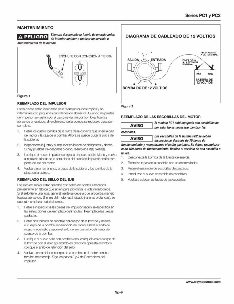
MANTENIMIENTO Siempre desconecte la fuente de energía antes
de intentar instalar o realizar un servicio o mantenimiento de la bomba.
TEST RESET
Figura 1
ENCHUFE CON CONEXIÓN A TIERRA
REEMPLAZO DEL IMPULSOREstas piezas están diseñadas para manejar líquidos limpios y no inflamables con pequeñas cantidades de abrasivos. Cuando las paletas del impulsor se gastan por el uso o se dañan por bombear líquidos abrasivos o residuos, el rendimiento de la bomba se reduce o cesa por completo. 1. Retire los cuatro tornillos de la placa de la cubierta que unen la caja
del motor y la caja de la bomba. Ahora se puede quitar la placa de la cubierta.
2. Inspeccione la junta y el impulsor en busca de desgastes y daños. Si hay pruebas de desgaste o daño, reemplace la(s) pieza(s).
3. Lubrique el nuevo impulsor con grasa blanca o aceite liviano y vuelva a instalarlo alineando la cara plana del cubo del impulsor con la cara plana del eje del motor.
4. Vuelva a montar la junta, la placa de la cubierta y los tornillos de la placa de la cubierta.
REEMPLAZO DEL SELLO DEL EJELos ejes del motor están sellados con sellos de bordes lubricados previamente en fábrica que sirven para prolongar la vida de la bomba. Si el sello tiene una fuga, generalmente se debe a que la bomba manejó líquidos abrasivos. Si el eje del motor está rayado (ranuras profundas), se deberá reemplazar toda la bomba. 1. Retire e inspeccione las piezas del impulsor según se especifica en
las instrucciones de reemplazo del impulsor. Reemplace las piezas gastadas.
2. Retire dos tornillos de montaje del cuerpo de la bomba y deslice el cuerpo de la bomba separándolo del motor. Reitre el anillo de retención del sello y saque el sello del eje gastado del interior del cuerpo de la bomba.
3. Lubrique el nuevo sello con aceite liviano, colóquelo en el cuerpo de la bomba con el labio apuntando en dirección opuesta al motor y coloque el anillo de retención del sello.
4. Vuelva a ensamblar el cuerpo de la bomba en el motor con los tornillos de montaje. Siga los pasos 3 y 4 de Reemplazo del impulsor.
DIAGRAMA DE CABLEADO DE 12 VOLTIOS
PINZA ROJA A LA TERMINAPOSITIVA
PINZA NEGRAA LA TERMINAL
POS+
BATERÍA DE 12 VOLTIOS
-NEG
BOMBA DC DE 12 VOLTIOS
ENTRADASALIDA
Figura 2
REEMPLAZO DE LAS ESCOBILLAS DEL MOTOR El modelo PC1 está equipado con escobillas de
por vida. No es necesario cambiar las escobillas. Las escobillas de la bomba PC2 se deben
inspeccionar después de 75 horas de funcionamiento y reemplazarse si están gastadas. Se deben reemplazar cada 100 horas de funcionamiento. Realice el servicio de una escobilla a la vez..1. Desconecte la bomba de la fuente de energía. 2. Retire las tapas de la escobilla con un destornillador.3. Retire el ensamble de escobillas desgastado.4. Introduzca el nuevo ensamble de escobillas.5. Vuelva a colocar las tapas de las escobillas.

Sp-10
www.waynepumps.com
Manual de instrucciones de funcionamiento y piezas de repuesto
GUÍA DE DIAGNÓSTICO DE AVERÍASSíntoma Causa(s) Posible(s) Medida Correctiva
La bomba no enciende o no funciona 1. Fusible quemado 1. Si está quemado, cámbielo por un fusible del tamaño correcto o reajuste el disyuntor
2. Bajo voltaje 2. El voltaje del suministro de energía debe coincidir con el voltaje de la bomba
3. Escobillas gastadas 3. Cambie las escobillas (solamente PC2)
4. Impulsor bloqueado 4. Elimine la obstrucción
5. El motor se ha sobrecalentado (solamente el modelo PC2)
5. Desconecte de la fuente de energía y deje enfriar (mín. 10 minutos)
La bomba no se ceba o no retiene el ceba-do después del funcionamiento
1. Fuga de aire en la línea de succión 1. Repare la línea de succión ajustando la conexión de entrada o reemplácela
2. Impulsor bloqueado 2. Elimine la obstrucción
3. Sello gastado 3. Reemplace el sello
4. Altura de succión demasiado alta 4. Baje la bomba
5. Manguera doblada o con bucles 5. Enderece la manguera
6. Accesorios no ajustados 6. Ajuste los accesorios
7. La manguera de succión está fuera del agua
7. Sumerja el extremo de succión de la manguera
8. Entrada obstruida 8. Limpie la entrada
La velocidad de flujo es muy lenta 1. Manguera de entrada obstruida o doblada 1. Limpie o reemplace
2. Bajo voltaje 2. El voltaje del suministro de energía debe coincidir con el voltaje de la bomba
El sello del eje tiene fugas 1. Sello gastado 1. Reemplace el sello
2. Eje con ranuras 2. Reemplace la bomba
3. Cabezal de la bomba suelto en el motor 3. Asegúrese de que esté correctamente armado y no tenga obstrucciones, ajuste los pernos
Sp-11
www.waynepumps.com
Series PC1 y PC2
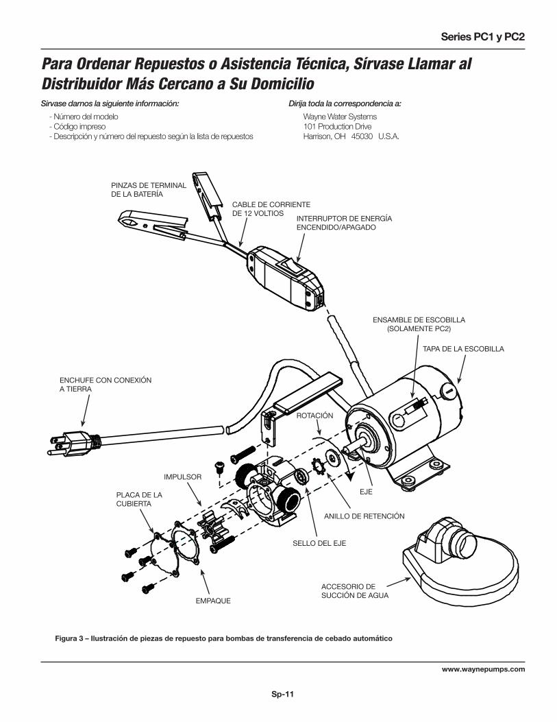
Figura 3 – Ilustración de piezas de repuesto para bombas de transferencia de cebado automático
PINZAS DE TERMINAL DE LA BATERÍA
CABLE DE CORRIENTE DE 12 VOLTIOS INTERRUPTOR DE ENERGÍA
ENCENDIDO/APAGADO
TAPA DE LA ESCOBILLA
ENSAMBLE DE ESCOBILLA (SOLAMENTE PC2)
ENCHUFE CON CONEXIÓN A TIERRA
EJE
ROTACIÓN
ANILLO DE RETENCIÓN
SELLO DEL EJE
IMPULSOR
PLACA DE LA CUBIERTA
EMPAQUE
ACCESORIO DE SUCCIÓN DE AGUA
Para Ordenar Repuestos o Asistencia Técnica, Sírvase Llamar al Distribuidor Más Cercano a Su DomicilioSirvase darnos la siguiente información: Dirija toda la correspondencia a: - Número del modelo Wayne Water Systems - Código impreso 101 Production Drive - Descripción y número del repuesto según la lista de repuestos Harrison, OH 45030 U.S.A.

Sp-12
www.waynepumps.com
Manual de instrucciones de funcionamiento y piezas de repuesto
Garantie LimitéeDurante un año a partir de la fecha de compra, Wayne Water Systems (“Wayne”) reparará o reemplazará, según lo decida, para el comprador original, cualquier pieza o piezas de sus Bombas para cloacas o Bombas de agua (“Producto”) que después de un examen sea(n) hallada(s) por Wayne como defectuosa(s) en su material o mano de obra. Sírvase llamar a Wayne (800-237-0987) para obtener instrucciones o consulte a su distribuidor. Esté preparado para proporcionar los números de modelo y serie cuando ejerza el derecho a esta garantía. Todos los gastos de transporte de los productos o piezas enviadas para su reparación o reemplazo serán a cargo del comprador.Esta Garantía limitada no cubre productos que estén dañados debido a accidentes, abuso, uso indebido, negligencia, instalación incorrecta, mantenimiento inadecuado, o no hacerlo funcionar según las instrucciones escritas de Wayne.NO EXISTE NINGUNA OTRA GARANTÍA EXPRESA. LAS GARANTÍAS IMPLÍCITAS, INCLUYENDO AQUELLAS DE COMERCIABILIDAD E IDONEIDAD PARA UN PROPÓSITO EN PARTICULAR, ESTÁN LIMITADAS A UN AÑO A PARTIR DE LA FECHA DE COMPRA. ÉSTE ES EL RECURSO EXCLUSIVO Y SE EXCLUYE CUALQUIER RESPONSABILIDAD POR CUALESQUIER DAÑOS O GASTOS INDIRECTOS O CONSECUENTES.Ciertos estados no permiten limitaciones sobre el período de duración de las garantías implícitas, ni permiten las exclusiones ni limitaciones de los daños incidentales o consecuentes, de forma que las limitaciones mencionadas anteriormente pueden no aplicarse a usted. Esta garantía limitada le otorga derechos legales específicos y también puede tener otros derechos legales que pueden variar dependiendo del estado.Bajo ningún concepto, ya sea por incumplimiento del contrato de garantía, incumplimiento extracontractual (incluso negligencia) o de otro modo, WAYNE o sus proveedores serán responsables de ningún daño especial, consecuente, incidental o penal, que incluye, pero no se limita a pérdida de ganancias, pérdida de uso del producto o cualquier equipo asociado, daños al equipo asociado, costo de capital, costo de productos sustitutos, instalaciones, servicio o reemplazo de energía, costos de inutilidad, o reclamos de clientes del comprador por dichos daños.Usted DEBE conservar su recibo de compra junto con este formulario. En caso de tener que ejercer un reclamo de garantía, DEBE enviar una copia del recibo de compra junto al material o correspondencia. Llame a WAYNE (800-237-0987) para obtener autorizaciones e instrucciones de devolución.
NO ENVÍE ESTE FORMULARIO A WAYNE. Use este formulario sólo para mantener sus archivos.
NO. DE MODELO_________________ NO. DE SERIE____________________________ FECHA DE INSTALACIÓN_______________
ADJUNTE AQUÍ SU RECIBO