Reactive Routing Protocol for Mobile Ad-Hoc Networks · Reactive Routing Protocol for Mobile Ad-Hoc...
66
Reactive Routing Protocol for Mobile Ad-Hoc Networks A Thesis Submitted in Partial Fulfillment of the Requirements for the Degree of Master of Technology in Computer Applications By Arun Mukhija Under Guidance of Dr. Ranjan Bose (Department of Electrical Engineering) Department of Mathematics Indian Institute of Technology, Delhi December 2001
Transcript of Reactive Routing Protocol for Mobile Ad-Hoc Networks · Reactive Routing Protocol for Mobile Ad-Hoc...
Reactive Routing Protocol
for
Mobile Ad-Hoc Networks
A Thesis Submitted in Partial Fulfillment of the Requirements for the
Degree of
Master of Technology in
Computer Applications
By
Arun Mukhija
Under Guidance of
Dr. Ranjan Bose (Department of Electrical Engineering)
Department of Mathematics
Indian Institute of Technology, Delhi
December 2001
Reactive Routing Protocol for Mobile Ad-Hoc Networks 1
CERTIFICATE
This is to certify that the dissertation entitled �Reactive Routing Protocol for Mobile
Ad-Hoc Networks� submitted by Arun Mukhija in partial fulfillment for the award of
the degree of Master of Technology in Computer Applications to Indian Institute of
Technology Delhi, is a bona fide record of work carried out by him under my
supervision and guidance. This work has not been submitted elsewhere for the award
of any degree or diploma.
Dr. Ranjan Bose Department of Electrical Engineering
Indian Institute of Technology Delhi

Reactive Routing Protocol for Mobile Ad-Hoc Networks 2
Acknowledgement
I have great pleasure in expressing my heartiest gratitude to my project guide Dr.
Ranjan Bose for his able guidance, valuable suggestions, constructive criticism and for
providing a clear direction to the project from time to time. His continuous
encouragement and guidance has been a constant source of inspiration throughout this
project.
Thanks are also due to the faculty members of Department of Mathematics and our
program coordinator Dr. S. K. Gupta for their support and encouragement.
Arun Mukhija Department of Mathematics
Indian Institute of Technology Delhi

Reactive Routing Protocol for Mobile Ad-Hoc Networks 3
Abstract
Reactive Routing Protocol is a bandwidth efficient on-demand routing protocol for
Mobile Ad-Hoc Networks. The protocol comprises of two main functions of Route
Discovery and Route Maintenance. Route Discovery function is responsible for the
discovery of new route, when one is needed and Route Maintenance function is
responsible for the detection of link breaks and repair of an existing route. The
protocol achieves its bandwidth efficiency by using Incremental Search Method for
Route Discovery and Surroundings Repair Method for Route Maintenance.
Incremental Search Method limits the number of routing messages such that the
number of links traversed during Route Discovery are minimized and hence
bandwidth is efficiently utilized. And by using Surroundings Repair Method a node
attempts to repair its surroundings in the event of a link failure, in order to find an
alternate route skipping this broken link and thus it attempts to minimize the routing
overhead. Simulation results illustrate the performance and demonstrate efficient
utilization of bandwidth by Reactive Routing Protocol.
Reactive Routing Protocol for Mobile Ad-Hoc Networks 4
Contents
1. Introduction 5
1.1. Mobile Ad-Hoc Networks (MANETs) 5
1.2. Routing in MANETs 5
1.3. Other Routing Protocols Suggested for MANETs 6
1.4. Layout of the Thesis 8
2. Overview of Reactive Routing Protocol 9
2.1. Route Discovery 9
2.2. Route Maintenance 15
3. Detailed Operation of Reactive Routing Protocol 18
3.1. Packet Formats of Routing Packets 19
3.2. Data Structures Maintained by Each Mobile Node 23
3.3. Event � Action Plans 27
4. Performance Evaluation 50
5. Further Optimizations 57
6. Future Work 59
7. Conclusion 60
References 61
Appendix 64
A.1. Terminology Used 64
A.2. List of Acronyms 65
Reactive Routing Protocol for Mobile Ad-Hoc Networks 5
Chapter - 1
Introduction _____________________________________________________________________
1.1. Mobile Ad-Hoc Networks (MANETs)
A Mobile Ad-Hoc Network (MANET) is an infrastructureless collection of mobile
nodes that can arbitrarily change their geographic locations such that these networks
have dynamic topologies which are composed of bandwidth constrained wireless
links.
MANET nodes are equipped with wireless transmitters and receivers. At a given time
depending on the nodes positions and their transmitter and receiver coverage patterns
and transmission power levels, a wireless connectivity in the form of a random,
multi hop graph or ad-hoc network exists between the nodes. This ad-hoc topology
may change with time as the nodes move or change their transmission and reception
parameters [1].
The current applications of MANETs are in defense operations, emergency search-
and-rescue operations, meetings and conventions and other scenarios where quick
sharing of information is desired without any fixed infrastructure available [2]. But in
future there could be many more commercial applications of these networks.
1.2. Routing in MANETs
To enable communication within a MANET, a routing protocol is required to establish
routes between participating nodes. Because of limited transmission range, multiple
Reactive Routing Protocol for Mobile Ad-Hoc Networks 6
network hops may be needed to enable data communication between two nodes in the
network. Since MANET is an infrastructureless network, each mobile node operates
not only as a host but also as a router, forwarding packets for other mobile nodes in
the network [1, 3].
There are frequent unpredictable topological changes in these networks, which makes
the task of finding and maintaining routes as difficult. Conventional routing protocols
based on distance vector or link state algorithms can not be applied here, since the
amount of routing related traffic would waste a large portion of the wireless
bandwidth, and such discovered routes would soon become obsolete due to mobility of
nodes [3, 4, 5].
In MANETs mobile nodes share the same frequency channel thereby limiting the
network capacity. Thus one of the highly desirable properties of a routing protocol for
MANETs is that it should be bandwidth efficient.
1.3. Other Routing Protocols Suggested for MANETs
Several routing protocols have been proposed for MANETs, which differ in the
approach used for discovering a new route and maintaining a known route when nodes
move. These protocols can be broadly classified as
(a) proactive routing protocols such as DSDV [6], FSR [7], WRP [8, 9], CGSR [10],
GSR [11] etc.
(b) on-demand routing protocols such as DSR [12, 13, 14], AODV [15, 16], TORA
[17, 18], ABR [19] etc.
In the proactive routing protocols nodes continuously search for routing information
within the network, so that when a route is needed it is already available. While in the
on-demand routing protocols a route is searched when it is needed.
Reactive Routing Protocol for Mobile Ad-Hoc Networks 7
In the proactive routing protocols as compared to the on-demand routing protocols, a
constant propagation of routing information is involved, which incurs substantial
routing related traffic. Moreover such protocols require each mobile node to maintain
routes to each possible target in the MANET, which most likely exceeds the
requirements of any node and thus the routing overhead expended in establishing such
unrequired routes is wasted. Since bandwidth is a scarce resource in MANETs, these
limitations imposed by proactive routing protocols make them less attractive as
compared to on-demand routing protocols in a bandwidth constrained MANET
environment. ZRP [20] presents a hybrid behavior of proactive and reactive routing
schemes which has advantages and disadvantages of both the schemes, depending on
the value chosen for zone radius parameter used to limit the scope of proactive
scheme.
The on-demand routing protocols suggested for MANETs, such as Dynamic Source
Routing (DSR) Protocol [12, 13], Ad-Hoc On-Demand Distance Vector (AODV)
Routing [15, 16], Temporally Ordered Routing Algorithm (TORA) [17, 18] and
Associativity Based Routing (ABR) [19] etc., basically make use of broadcast based
methods for route discovery. They differ in their routing packet formats, data
structures maintained by each node, various optimizations applied in route discovery
and in their approach for maintaining routes.
In a broadcast based method, when an originator node wants to send data packets to a
target node, and it does not have a valid route to this target node, it broadcasts a route
request packet to its neighbors. These neighbors forward the route request packet to
their neighbors and this process goes on until either the target node or an intermediate
node with a valid route to target node is located. Each node receiving a particular route
request packet broadcasts it only once to its neighbors, and it discards the subsequent
receptions of the same route request packet, to minimise routing overhead. Duplicate
receptions are detected using sequence numbers associated with route request packets.
This method of route discovery floods the entire network with the route request
packets thus this method of route discovery is also called Flooding Method.

Reactive Routing Protocol for Mobile Ad-Hoc Networks 8
The shortcoming of Flooding Method is that it floods the entire network with the route
requests even when the target node is just a few hops away from the originator node.
An improvement over the Flooding Method, as suggested by the authors of AODV
Routing [16] to reduce the wastage of bandwidth of a MANET, is the Expanding Ring
Method. In the Expanding Ring Method, the originator node initially uses a time to
live (TTL) field equal to some constant in the route request packet and initiates the
route discovery as before. When no valid route is received by the originator node
within a certain timeout interval, it increments the TTL field of route request packet
and reinitiates route discovery process. This process goes on till a valid route is
received by the originator node or upto a maximum number of retries.
Expanding Ring Method although better than the Flooding Method in terms of overall
bandwidth utilization of MANET, is still not a very efficient method, as it still wastes
a lot of bandwidth due to redundant link traversals. In fact Expanding Ring Method is
sometimes more expensive than Flooding Method, e.g. when the originator node and
target node lie at opposite extremes of the network.
This wastage of bandwidth in case of Flooding Method and Expanding Ring Method
is because each participating node normally receives route request packets from all its
neighbors and except for the first one all subsequent receptions are redundant. Thus
although these methods of route discovery are simple in operation but this simplicity
comes at the cost of wasting valuable bandwidth.
1.4. Layout of the Thesis
Chapter 2 gives an overview of a more bandwidth-efficient routing protocol for
MANETs, called �Reactive Routing Protocol�. The detailed operation of Reactive
Routing Protocol is given in Chapter 3. Chapter 4 presents the simulation results and
discusses performance evaluation. Chapter 5 suggests some further optimizations.
Chapter 6 gives the scope for future work and Chapter 7 concludes the work.

Reactive Routing Protocol for Mobile Ad-Hoc Networks 9
Chapter - 2
Overview of Reactive Routing Protocol _____________________________________________________________________
Reactive Routing Protocol (RRP) is a bandwidth-efficient on-demand routing protocol
for MANETs. In this protocol the originator node initiates the route search process,
whenever it needs to send data packets to a target node. Thus the need for a route
triggers the process of route search, hence the name Reactive Routing Protocol.
RRP is intended to be implemented in the network layer of mobile nodes i.e. in the
layer 3 of ISO OSI reference model. Route Discovery and Route Maintenance
functions of the protocol are described next.
2.1. Route Discovery
RRP is different from other suggested on-demand routing protocols, mainly in the way
that it does not use any broadcast based method for new route discovery but uses the
Incremental Search Method (ISM), thus making it more bandwidth-efficient and
reducing the number of links traversed for the same routes discovered as compared to
a broadcast based method .
In the Incremental Search Method of RRP, each node �A� maintains a list of its
immediate neighbors i.e. the nodes that have direct communication link with �A�. In
addition to the address of neighbor, �A� also records the link cost to this neighbor and
the time of neighbor discovery in its neighbor list. This time of neighbor discovery is
recorded only once for each new neighbor discovered and is not changed during the
re-discovery of an existing neighbor. The neighbor list is maintained by periodically
sending �Echo� packets by each node and the node receiving �Echo� packet is
_____________________________________________________________________
Broadcast based method here stands for Flooding Method and Expanding Ring Method etc.

Reactive Routing Protocol for Mobile Ad-Hoc Networks 10
required to respond back immediately. Measurement of the round-trip time and
dividing it by two gives the link cost to this neighbor [4]. The neighbor list is used not
just for route discovery but also for route maintenance and can be used for other
optimizations to the protocol.
Under the Incremental Search Method, whenever an originator node �O� needs to send
data packets to a target node �T� and it has a valid route to �T� in its routing tables or
neighbor list, it can proceed with the data transfer to �T� through this route. Else if
�O� could not find a valid route to �T� and the route discovery process for �T� is not
currently on, �O� would send a route discovery packet with an incremented value of
Dis_Identification Number for this target node �T�, to each of its neighbors from the
neighbor list. �O� also maintains a list of the nodes to which it has sent route discovery
packets for each target node �T�, in its Discovery Table. Originator Address, Target
Address and Dis_Identification Number uniquely identify a route discovery packet.
Each node �A� that receives a route discovery packet would look for a route to �T� in
its routing tables and neighbor list. In case �A� finds a route to �T� in its routing tables
or neighbor list, it would send a route verification packet to �T� so that �T� could reply
with a route confirmation packet back to �O�. This is done to ensure that this route is
valid and is not broken. If no route confirmation packet is received by �A� within a
certain timeout period associated with each sending of route verification packet, then
�A� can presume that this route is not valid anymore. So in the case that �A� does not
have a valid route to �T� or it could not find any route to �T� in its routing tables or
neighbor list, �A� would send a route response packet back to �O�, which would
contain the list of nodes that are immediate neighbors of �A�. �A� also records the
reverse path towards �O� in its temporary routing table with the next hop being the
node that last forwarded this route discovery packet.
On receiving such a route response packet from node �A� the intermediate nodes
record the forward path towards �A� in their temporary routing tables with the next
hop being the node that last forwarded this route response packet. When the originator

Reactive Routing Protocol for Mobile Ad-Hoc Networks 11
node �O� receives route response packet, it considers each of neighbor node �X� of �A�
to send route discovery packet, only if it has not sent a route discovery packet to �X�
before, by looking at its entry in Discovery Table. Thus the repeated sendings of route
discovery packet are avoided and each node receives route discovery packet for a
particular route discovery at most once. �O� records forward path to all such neighbors
of �A� to which it intends to send route discovery packets, in its temporary routing
table with the next hop being the node that last forwarded this route response packet,
and also lists them in the corresponding entry in its Discovery Table. �O� then lists all
such neighbors to which it intends to send route discovery packets, in a single route
discovery packet and forwards it to �A� and �A� in turn forwards it to each of these
nodes individually. This saves multiple sendings of individual route discovery packets
to each of these nodes on the same links and hence saves bandwidth.
This process goes on till either �O� receives a route confirmation packet from �T�,
which means route is discovered successfully, or till all the nodes reachable from �O�
have been covered in which case it can conclude that node �T� is currently unreachable
from node �O�. This conclusion of �T� being currently unreachable from �O� is drawn
automatically after a certain timeout period associated with each new route discovery
in the Discovery Table.
In case of target node �T� being currently unreachable, the originator node �O� may
restart the route discovery for �T� after waiting for a certain time, in the hope that the
network topology might have changed during this time due to mobility of nodes and
�T� would now have become reachable through some route from �O�.
A route discovery process might return more than one route from �O� to �T�, in which
case �O� would keep most optimal route in its Active Routing Table and other routes
in its Passive Routing Table. The Passive Routing Table helps in expediting future
route discoveries or when the route in Active Routing Table gets broken. The metric to
decide most optimal route to keep in Active Routing Table can be Hop Count i.e.
number of links from �O� to �T� or the Route Cost which is sum of the link costs of all

Reactive Routing Protocol for Mobile Ad-Hoc Networks 12
links from �O� to �T�. In case of a tie with one metric, the other metric is used as the
deciding factor for the most optimal route and if both metrics are equal the route
bearing lower route number i.e. the route first confirmed by �T� is kept in Active
Routing table and the others in Passive Routing Table.
In RRP, routing tables need to maintain only next hop and next to next hop
information for each target entry and not the complete route upto the target node thus
saving table space. Next to next hop information is used for Route Maintenance as
described in the next sub-section. Similarly the data packets need to contain only the
target node address and not the complete source route, like in DSR Protocol [12], thus
cutting down the overhead incurred in carrying complete source route with every data
packet sent.
Routes recorded in the Active Routing Table are associated with a timeout field. Each
time a route is used for forwarding data packets its associated timeout field is updated
to its new value. If a route is not used before its timeout value is reached, it gets
deleted from Active Routing Table and is entered in Passive Routing Table. Similarly
each route present in a temporary routing table is associated with a timeout field and
each time this route is used for forwarding routing packets its associated timeout field
is updated to its new value. If this route is not used before its timeout value is reached,
it gets deleted from temporary routing table and may be entered in Passive Routing
Table, if space permits. Routes in the Passive Routing Table are not associated with
any timeout field but with a time field corresponding to the time when this route was
last used. Passive Routing Tables can have an upper bound on its size and can be
maintained as a first in first out data structure to limit its growth. Whenever a route
present in Passive Routing Table is intended to be used for forwarding data packets,
e.g. in the event of an active route being broken, and this route in Passive Routing
Table is older than some threshold route life, then a route verification packet is sent to
the target node of this route. And the route can be used only after getting route
confirmation packet from the target node to ensure that this route is currently valid and
is not broken.

Reactive Routing Protocol for Mobile Ad-Hoc Networks 13
As an illustration of the Incremental Search Method, for the similar network topology,
26 links are traversed during route discovery process in case of broadcast method as in
Figure 1(a), while in case of Incremental Search Method only 20 links are traversed as
in Figure 1(b).
Thus the main advantage of Incremental Search Method is that the number of links
traversed for a particular route discovery are reduced as compared to a broadcast based
method, which makes RRP more bandwidth efficient. This bandwidth-efficiency of
RRP is all the more evident with the increase in degree of each node because
redundant link traversals are totally avoided here.
Another major advantage of this method is that node �O� and other intermediate nodes
know the routes to several other nodes in the network apart from �T� through their
temporary routing tables, which can be stored in their Passive Routing Tables in case
the space permits. This would fasten the future route discoveries as the nodes would
now have thicker routing tables, thereby reducing the routing overhead for future route
discoveries and adding more to the bandwidth efficiency of RRP.

Reactive Routing Protocol for Mobile Ad-Hoc Networks 14
C T
A
D
O
E
B
F
(a)
C T
A
D
O
E
B
F
(b)
Figure 1: Route discovery process showing link traversals by routing packets in
(a) broadcast method, and (b) Incremental Search Method of RRP.
No. of Links Traversed = 26
Route Discovery Packet / Route Verification Packet
Route Confirmation Packet
Route Discovery Packet / Route Verification Packet
Route Confirmation Packet
Route Response Packet
No. of Links Traversed = 20

Reactive Routing Protocol for Mobile Ad-Hoc Networks 15
2.2. Route Maintenance
RRP uses Surroundings Repair Method (SRM), for the detection of link breaks and
repair of an existing route. To implement Surroundings Repair Method each node
keeps record of next hop and next to next hop for each target entry in its routing
tables . This method works both proactively and reactively.
In the proactive approach, each node �A� when it detects a change in its neighbor list
in the way that its link to an old neighbor node �B� is now broken, it initiates
Surroundings Repair Method for those routes in its Active Routing Table that use �B�
as their next hop. In the reactive approach, when node �A� is unable to forward data
packets to node �B� due to a break in its link to �B�, it initiates Surroundings Repair
Method for all those routes in its Active Routing Table that use �B� as their next hop.
In this method �A� attempts to repair each route in its Active Routing Table that uses
�B� as its next hop by finding an alternate route to its next to next hop �C� towards the
target node �T�. �A� sends a route repair packet for the node �C� to all its neighbors
from the neighbor list. In case a neighbor node �N� receiving route repair packet has
�C� as its immediate neighbor, it forwards route repair packet to �C� so that �C� could
reply with a route repair confirmation packet back to �A� through �N� so that �N� could
record this route in its Active Routing Table. Else if �N� does not have �C� as its
immediate neighbor it ignores this route repair packet. In case �A� receives a route
repair confirmation packet from �C� through �N� before a certain timeout period it
means route is repaired successfully with the hop count of repaired route being same
as that of original route and only the segment �A�-�B�-�C� of original route being
replaced now by �A�-�N�-�C� and the routing tables are modified accordingly. �A� can
now proceed with the data transfer through this repaired route. Else if no route repair
confirmation packet is received by �A� within a certain timeout period associated with
_____________________________________________________________________
The next to next hop information can be obtained from the next hop node, as next to next
hop is the next hop of next hop towards target node.

Reactive Routing Protocol for Mobile Ad-Hoc Networks 16
each route repair attempt, �A� sends a route invalid packet back to the originator node
�O�. The intermediate nodes and the node �O�, after receiving route invalid packet,
delete this route from their Active Routing Tables and may enter it in their Passive
Routing Tables, if the space permits. The originator node �O� can now reinitiate the
process of route search for the target node �T� if it intends to send more data packets to
node �T�.
The motivation behind Surroundings Repair Method is that there may be a small local
change in the network topology such that the link from �A� to �B� is broken but the
overall network topology has not changed significantly.
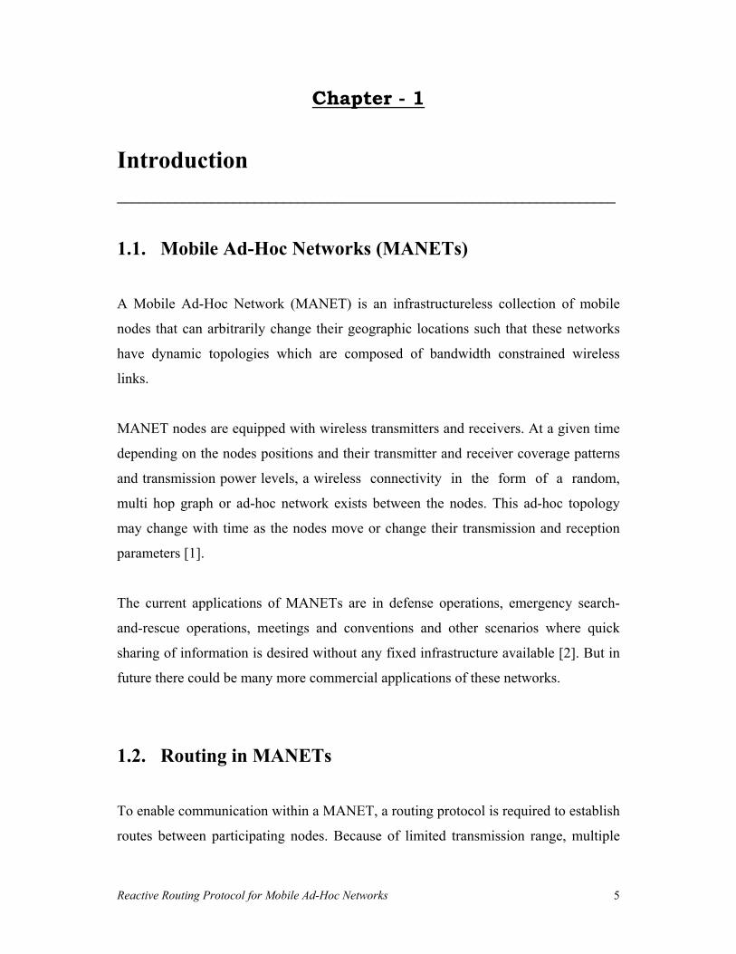
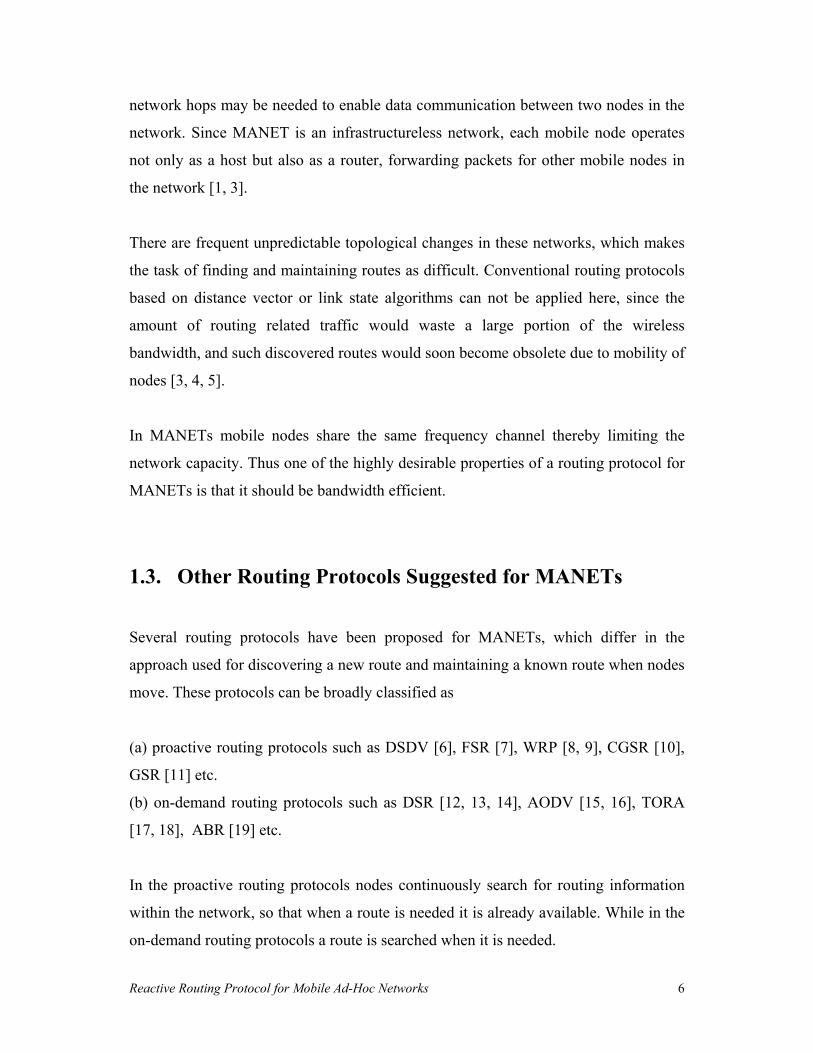
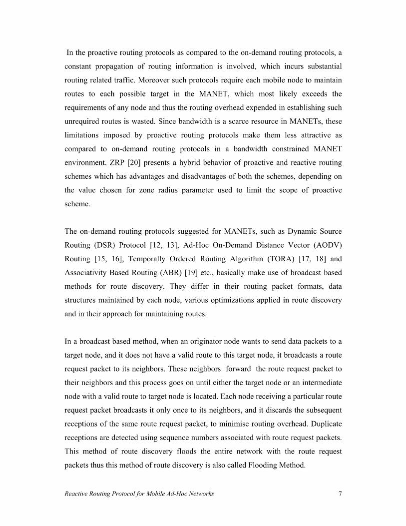
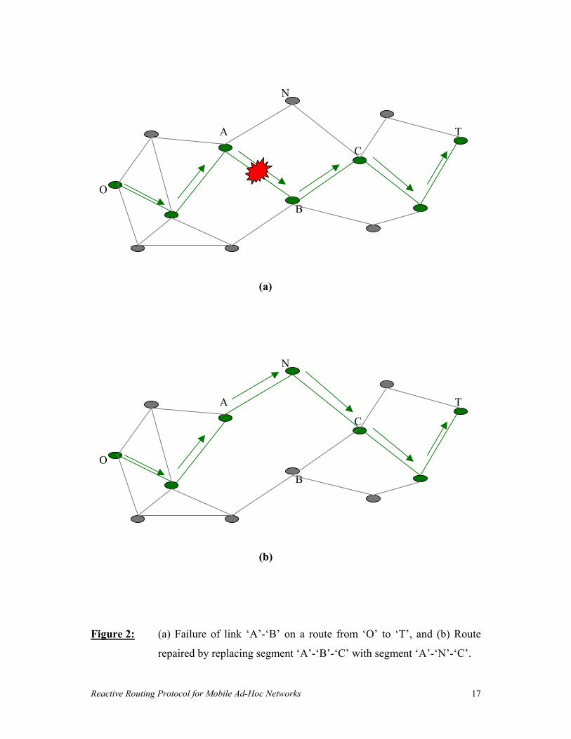
As an example, Figure 2(a) illustrates break in the link �A�-�B� in a route from �O� to
�T� before running Surroundings repair Method, while Figure 2(b) illustrates the
repaired route with the segment �A�-�B�-�C� now replaced by the segment �A�-�N�-�C�
after running Surroundings Repair Method.
The advantage of Surroundings Repair Method is that if a route is repaired
successfully the overhead incurred in sending a route invalid packet back to the
originator node and in initiating the new route search by the originator node is saved.
Thus the overall bandwidth efficiency of MANET is improved by using Surroundings
Repair Method.
Reactive Routing Protocol for Mobile Ad-Hoc Networks 17
N
A T
C
O
B
(a)
N
A T
C
O
B
(b)
Figure 2: (a) Failure of link �A�-�B� on a route from �O� to �T�, and (b) Route
repaired by replacing segment �A�-�B�-�C� with segment �A�-�N�-�C�.

Reactive Routing Protocol for Mobile Ad-Hoc Networks 18
Chapter - 3
Detailed Operation of Reactive Routing Protocol _____________________________________________________________________
Detailed operation of Reactive Routing Protocol is explained in the following sections
by means of:
(a) Details of Packet Formats of Routing Packets in section 3.1.
(b) Details of Data Structures Maintained by Each Mobile Node in section 3.2.
(c) Details of Event � Action Plans in section 3.3.
Reactive Routing Protocol for Mobile Ad-Hoc Networks 19
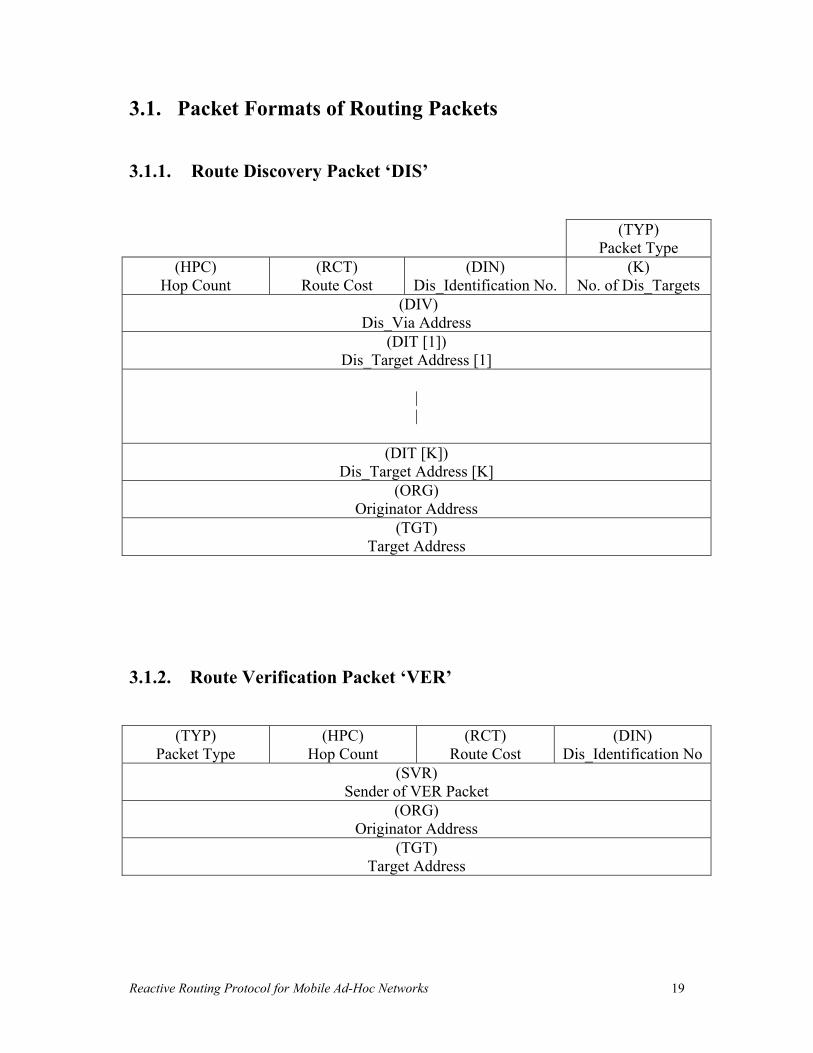
3.1. Packet Formats of Routing Packets
3.1.1. Route Discovery Packet �DIS�
(TYP) Packet Type
(HPC) Hop Count
(RCT) Route Cost
(DIN) Dis_Identification No.
(K) No. of Dis_Targets
(DIV) Dis_Via Address
(DIT [1]) Dis_Target Address [1]
| |
(DIT [K]) Dis_Target Address [K]
(ORG) Originator Address
(TGT) Target Address
3.1.2. Route Verification Packet �VER�
(TYP) Packet Type
(HPC) Hop Count
(RCT) Route Cost
(DIN) Dis_Identification No
(SVR) Sender of VER Packet
(ORG) Originator Address
(TGT) Target Address

Reactive Routing Protocol for Mobile Ad-Hoc Networks 20
3.1.3. Route Response Packet �RES�
(TYP) Packet Type
(HPC) Hop Count
(RCT) Route Cost
(DIN) Dis_Identification No.
(N) No. of Neighbors
(DIT) Dis_Target Address
(ORG) Originator Address
(TGT) Target Address
(NBR [1]) Neighbor Address [1]
| |
(NBR [N]) Neighbor Address [N]
(LCT [1]) Link Cost [1]
__ __ (LCT [N]) Link Cost [N]
3.1.4. Route Confirmation Packet �CON�
(TYP) Packet Type
(HPC) Hop Count
(RCT) Route Cost
(DIN) Dis_Identification No
(RON) Route No.
(NNT) Next to Next Hop towards Target
(ORG) Originator Address
(TGT) Target Address

Reactive Routing Protocol for Mobile Ad-Hoc Networks 21
3.1.5. Route Acknowledgement Packet �ACK�
(TYP) Packet Type
(DIN) Dis_Identification No
(RON) Route No.
(NNO) Next to Next Hop towards Originator
(ORG) Originator Address
(TGT) Target Address
3.1.6. Route Invalid Packet �INV�
(TYP) Packet Type
(INT) Invalid Type
(DIN) Dis_Identification No
(RON) Route No.
(SIN) Sender of INV Packet
(ORG) Originator Address
(TGT) Target Address
3.1.7. Route Modification Packet �MOD�
(TYP) Packet Type
(HPC) Hop Count
(RCT) Route Cost
(DIN) Dis_Identification No
(RON) Route No.
(NT) Next Hop towards Target
(NNT) Next to Next Hop towards Target
(ORG) Originator Address
(TGT) Target Address

Reactive Routing Protocol for Mobile Ad-Hoc Networks 22
3.1.8. Route Repair Packet �RPR�
(TYP) Packet Type
(HPC) Hop Count
(RCT) Route Cost
(DIN) Dis_Identification No
(RON) Route No.
(RPO) Repair_Originator Address
(RPT) Repair_Target Address
(ORG) Originator Address
(TGT) Target Address
3.1.9. Route Repair Confirmation Packet �RCN�
(TYP) Packet Type
(HPC) Hop Count
(RCT) Route Cost
(DIN) Dis_Identification No
(RON) Route No.
(RPO) Repair_Originator Address
(RPT) Repair_Target Address
(NNT) Next to Next Hop towards Target
(ORG) Originator Address
(TGT) Target Address

Reactive Routing Protocol for Mobile Ad-Hoc Networks 23
3.2. Data Structures Maintained by Each Mobile Node
3.2.1. Active Routing Table <Routing_Table (A)>
(DIN) Dis_Identification No.
(RON) Route No.
(ORG) Originat
or Address
(NH) Next Hop
Address
(NNH) Next to
Next Hop
Address
(TGT) Target
Address
(HPC) Hop
Count
(RCT) Route Cost
Timeout
3.2.2. Passive Routing Table <Routing_Table (P)>
(DIN) Dis_Identification No.
(RON) Route No.
(ORG) Originat
or Address
(NH) Next Hop
Address
(NNH) Next to
Next Hop
Address
(TGT) Target
Address
(HPC) Hop
Count
(RCT) Route Cost
Time

Reactive Routing Protocol for Mobile Ad-Hoc Networks 24
3.2.3. Discovery Table <DIS_Table>
(DIN) Dis_Identification
No.
(TGT) Target Address
Timeout
(NCD) Nodes Covered
RES Received
(Yes / No)
3.2.4. Dis_Identification Number Table <DIN_Table>
(DIN) Dis_Identification No.
(TGT) Target Address

Reactive Routing Protocol for Mobile Ad-Hoc Networks 25
3.2.5. Temporary Table <Temp_Table>
(NH) Next Hop Address
(TGT) Target Address
(HPC) Hop Count
(RCT) Route Cost
Timeout
3.2.6. Verification Table <VER_Table>
(DIN) Dis_Identific
ation No.
(ORG) Originator Address
(TGT) Target
Address
Timeout

Reactive Routing Protocol for Mobile Ad-Hoc Networks 26
3.2.7. Neighbor List <Neighbor_List>
(NBR) Neighbor Address
(LCT) Link Cost
Time
3.2.8. Route Repair Table <RPR_Table>
(DIN) Dis_Identific
ation No.
(RON) Route No.
(ORG) Originator Address
(TGT) Target
Address
Repair_Flag (Yes / No)
Timeout

Reactive Routing Protocol for Mobile Ad-Hoc Networks 27
3.3. Event � Action Plans
3.3.1. Event 1: Originator node �O� has packets to send to a Target node �T�
Caused by: Layer above network layer of node �O�
Action taken by node �O�:
1. Look for an entry of node �T� in the target address, (TGT) field of
Routing_Table (A). If a matching entry is found, start sending these packets
to �T� through its next hop (NH). Else proceed to step 2.
2. Look for an entry of node �T� in the (TGT) field of DIS_Table. If a matching
entry is found it means route discovery for �T� is currently on, so these packets
are kept in the buffer. Else proceed to step 3.
3. Look for an entry of node �T� in the neighbor address, (NBR) field of
Neighbor_List and next to next hop, (NNH) field of Routing_Table (A) and
(TGT) field of Temp_Table (s). If a matching entry is found, make a new entry
for this route in the Routing_Table (A) and start sending these packets to �T�.
Else proceed to step 4.
4. Look for an entry of node �T� in (TGT) field and (NNH) field of
Routing_Table (P). If a matching entry is found go to step 5, else go to step 6.
5. Calculate the difference in Current_Time and Time field of matched entry. If
this difference is less than Route_Life it means this route is still valid, make an
entry for this route in the Routing_Table (A) and start sending these packets to
�T�. Else if this difference is more than Route_Life, look for an entry of �T� in
the DIN_Table, if a matching entry is found increment this value, else make a
new entry in DIN_Table with (TGT) as �T� and Dis_Identification No., (DIN)
Reactive Routing Protocol for Mobile Ad-Hoc Networks 28
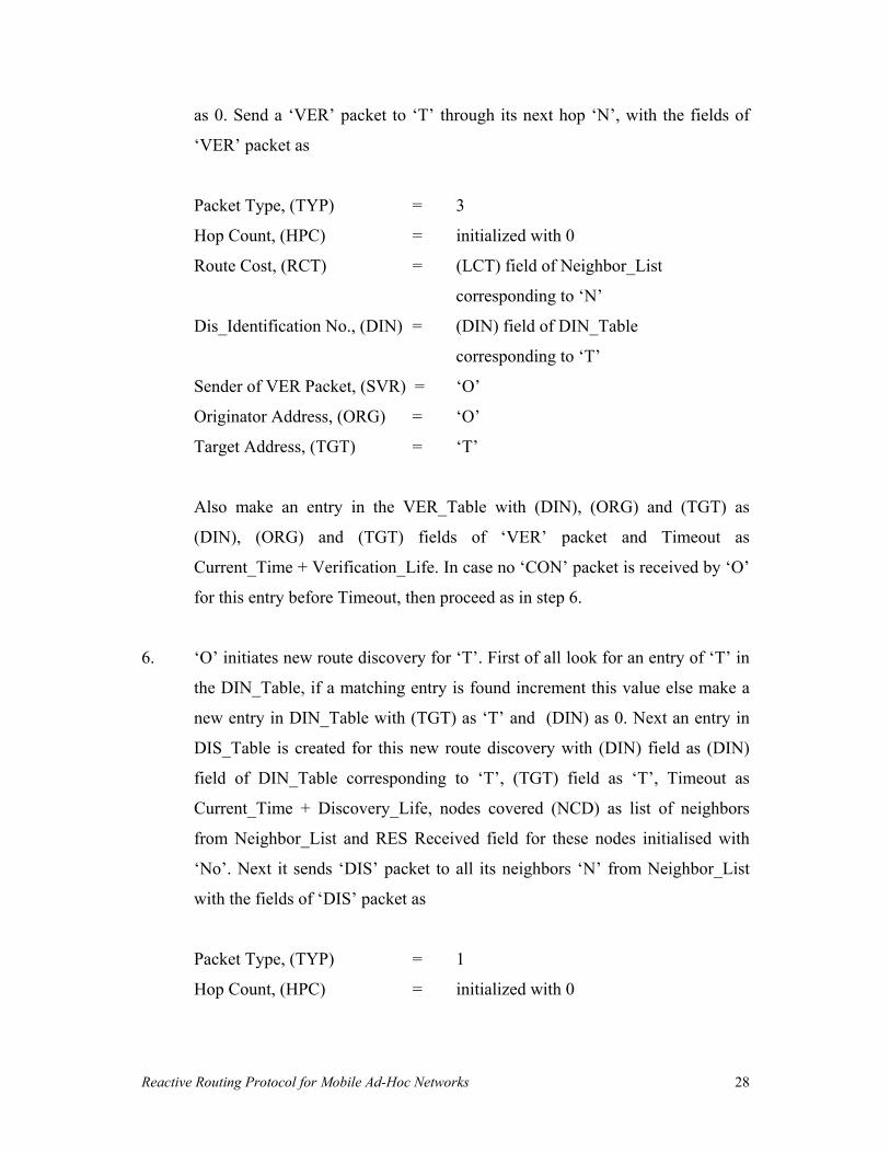
as 0. Send a �VER� packet to �T� through its next hop �N�, with the fields of
�VER� packet as
Packet Type, (TYP) = 3
Hop Count, (HPC) = initialized with 0
Route Cost, (RCT) = (LCT) field of Neighbor_List
corresponding to �N�
Dis_Identification No., (DIN) = (DIN) field of DIN_Table
corresponding to �T�
Sender of VER Packet, (SVR) = �O�
Originator Address, (ORG) = �O�
Target Address, (TGT) = �T�
Also make an entry in the VER_Table with (DIN), (ORG) and (TGT) as
(DIN), (ORG) and (TGT) fields of �VER� packet and Timeout as
Current_Time + Verification_Life. In case no �CON� packet is received by �O�
for this entry before Timeout, then proceed as in step 6.
6. �O� initiates new route discovery for �T�. First of all look for an entry of �T� in
the DIN_Table, if a matching entry is found increment this value else make a
new entry in DIN_Table with (TGT) as �T� and (DIN) as 0. Next an entry in
DIS_Table is created for this new route discovery with (DIN) field as (DIN)
field of DIN_Table corresponding to �T�, (TGT) field as �T�, Timeout as
Current_Time + Discovery_Life, nodes covered (NCD) as list of neighbors
from Neighbor_List and RES Received field for these nodes initialised with
�No�. Next it sends �DIS� packet to all its neighbors �N� from Neighbor_List
with the fields of �DIS� packet as
Packet Type, (TYP) = 1
Hop Count, (HPC) = initialized with 0

Reactive Routing Protocol for Mobile Ad-Hoc Networks 29
Route Cost, (RCT) = (LCT) field of Neighbor_List
corresponding to �N�
Dis_Identification No., (DIN) = (DIN) field of DIN_Table
corresponding to �T�
No. of Dis_Targets, (K) = 1
Dis_Via Address, (DIV) = �O�
Dis_Target Address, (DIT[1]) = �N�
Originator Address, (ORG) = �O�
Target Address, (TGT) = �T�
Note: �O�, �T� and �N� mean IP address of nodes �O�, �T� and �N�.
Reactive Routing Protocol for Mobile Ad-Hoc Networks 30
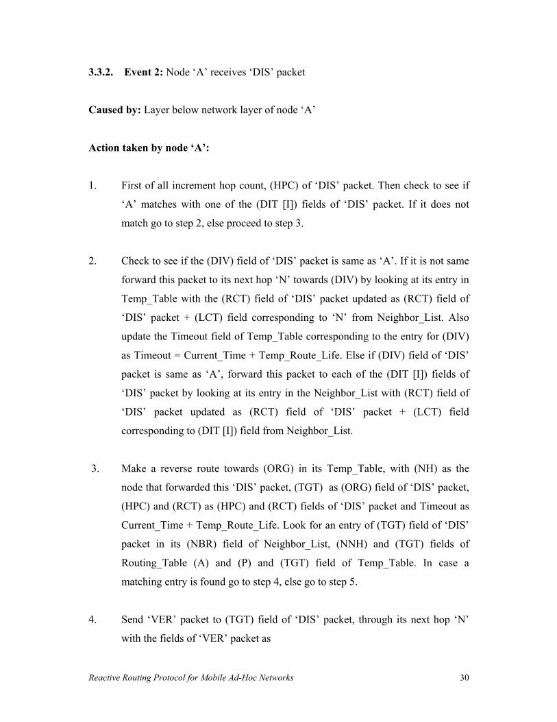
3.3.2. Event 2: Node �A� receives �DIS� packet
Caused by: Layer below network layer of node �A�
Action taken by node �A�:
1. First of all increment hop count, (HPC) of �DIS� packet. Then check to see if
�A� matches with one of the (DIT [I]) fields of �DIS� packet. If it does not
match go to step 2, else proceed to step 3.
2. Check to see if the (DIV) field of �DIS� packet is same as �A�. If it is not same
forward this packet to its next hop �N� towards (DIV) by looking at its entry in
Temp_Table with the (RCT) field of �DIS� packet updated as (RCT) field of
�DIS� packet + (LCT) field corresponding to �N� from Neighbor_List. Also
update the Timeout field of Temp_Table corresponding to the entry for (DIV)
as Timeout = Current_Time + Temp_Route_Life. Else if (DIV) field of �DIS�
packet is same as �A�, forward this packet to each of the (DIT [I]) fields of
�DIS� packet by looking at its entry in the Neighbor_List with (RCT) field of
�DIS� packet updated as (RCT) field of �DIS� packet + (LCT) field
corresponding to (DIT [I]) field from Neighbor_List.
3. Make a reverse route towards (ORG) in its Temp_Table, with (NH) as the
node that forwarded this �DIS� packet, (TGT) as (ORG) field of �DIS� packet,
(HPC) and (RCT) as (HPC) and (RCT) fields of �DIS� packet and Timeout as
Current_Time + Temp_Route_Life. Look for an entry of (TGT) field of �DIS�
packet in its (NBR) field of Neighbor_List, (NNH) and (TGT) fields of
Routing_Table (A) and (P) and (TGT) field of Temp_Table. In case a
matching entry is found go to step 4, else go to step 5.
4. Send �VER� packet to (TGT) field of �DIS� packet, through its next hop �N�
with the fields of �VER� packet as

Reactive Routing Protocol for Mobile Ad-Hoc Networks 31
Packet Type, (TYP) = 3
Hop Count, (HPC) = (HPC) field of �DIS� packet
Route Cost, (RCT) = (RCT) field of �DIS� packet +
(LCT) field of Neighbor_List corresponding to �N�
Dis_Identification No., (DIN) = (DIN) field of �DIS� packet
Sender of VER Packet, (SVR) = �A�
Originator Address, (ORG) = (ORG) field of �DIS� packet
Target Address, (TGT) = (TGT) field of �DIS� packet
Also make an entry in the VER_Table with (DIN), (ORG) and (TGT) as
(DIN), (ORG) and (TGT) fields of �VER� packet and Timeout as
Current_Time + Verification_Life. In case no �CON� packet is received by �A�
for this entry before Timeout, then proceed as in step 5.
5. Send a �RES� packet back to (ORG) through its next hop �N� by looking at its
entry in the Temp_Table, with the fields of �RES� packet as
Packet Type, (TYP) = 2
Hop Count, (HPC) = initialized with 0
Route Cost, (RCT) = (LCT) field of Neighbor_List
corresponding to �N�
Dis_Identification No., (DIN) = (DIN) field of �DIS� packet
No. of Neighbors, (N) = No. of neighbors in the
Neighbor_List of node �A�
Dis_Target Address, (DIT) = �A�
Originator Address, (ORG) = (ORG) field of �DIS� packet
Target Address, (TGT) = (TGT) field of �DIS� packet
Neighbor Addresses, (NBR [1] .. [N]) = (NBR) fields of Neighbor_List
Link Costs, (LCT [1] .. [N]) = (LCT) fields of Neighbor_list
corresponding to NBR [1] to [N]
Note: �A� and �N� mean IP address of nodes �A� and �N�.

Reactive Routing Protocol for Mobile Ad-Hoc Networks 32
3.3.3. Event 3: Node �A� receives �RES� packet
Caused by: Layer below network layer of node �A�
Action taken by node �A�:
1. Increment the hop count, (HPC) of �RES� packet. Then check to see if the
(ORG) field of �RES� packet is same as �A�. If it is not same go to step 2, else
proceed to step 3.
2. Make an entry for a route to (DIT) field of �RES� packet in its Temp_Table
with (NH) as node that forwarded this �RES� packet, (TGT) as (DIT) field of
�RES� packet, (HPC) and (RCT) as (HPC) and (RCT) fields of �RES� packet
and Timeout as Current_Time + Temp_Route_Life. Then forward this �RES�
packet to (ORG) field of �RES� packet through its next hop �N� by looking at
the entry for (ORG) in the (TGT) field of Temp_Table, with the (RCT) field of
�RES� packet updated as (RCT) field of �RES� packet + (LCT) field
corresponding to �N� from Neighbor_List. Also update the Timeout field of
Temp_Table corresponding to the entry for (ORG) as Timeout = Current_Time
+ Temp_Route_Life.
3. Look for an entry of (TGT) in DIS_Table, in case no matching entry is found it
means route for this (TGT) is already discovered and just discard this �RES�
packet. Else if a matching entry is found update the DIS_Table by making the
RES Received field corresponding to (DIT) as �Yes�. Then consider each of
(NBR [1]) to (NBR [N]) sent in �RES� packet to check if it is already there in
the (NCD) field of DIS_Table. In case it is already there ignore this address.
And if it is not there make an entry for this (NBR [I]) in the DIS_Table with
(NCD) as (NBR [I]) and RES Received as �No�, and at the same time make an
entry for a route to this (NBR[I]) in the Temp_Table with (NH) as the node �N�
that forwarded this �RES� packet, (TGT) as (NBR [I]), (HPC) as 1 + (HPC)

Reactive Routing Protocol for Mobile Ad-Hoc Networks 33
field of �RES� packet, (RCT) as (RCT) field of �RES� packet + LCT [I] field of
�RES� packet and Timeout as Current_Time + Temp_Route_Life. Let the
number of such (NBR [I]) nodes which are newly entered in DIS_Table be M.
Send a �DIS� packet to (DIT) field of �RES� packet (only if M > 0), through its
next hop �N�, with the fields of �DIS� packet as
Packet Type, (TYP) = 1
Hop Count, (HPC) = initialized with 0
Route Cost, (RCT) = (LCT) field of Neighbor_List
corresponding to �N�
Dis_Identification No., (DIN) = (DIN) field of �RES� packet
No. of Dis_Targets, (K) = M
Dis_Via Address, (DIV) = (DIT) field of �RES� packet
Dis_Target Address, (DIT[1]�[K]) = (NBR [I1]�[IM]) fields of �RES� packet
Originator Address, (ORG) = (ORG) field of �RES� packet
Target Address, (TGT) = (TGT) field of �RES� packet
Delete the entry corresponding to (DIT) field of �RES� packet from
Temp_Table and if the space permits enter this route in Routing_Table (P)
with Time as (Timeout field of Temp_Table � Temp_Route_Life) else discard
this route.
Note: �A� and �N� mean IP address of nodes �A� and �N�.
Reactive Routing Protocol for Mobile Ad-Hoc Networks 34
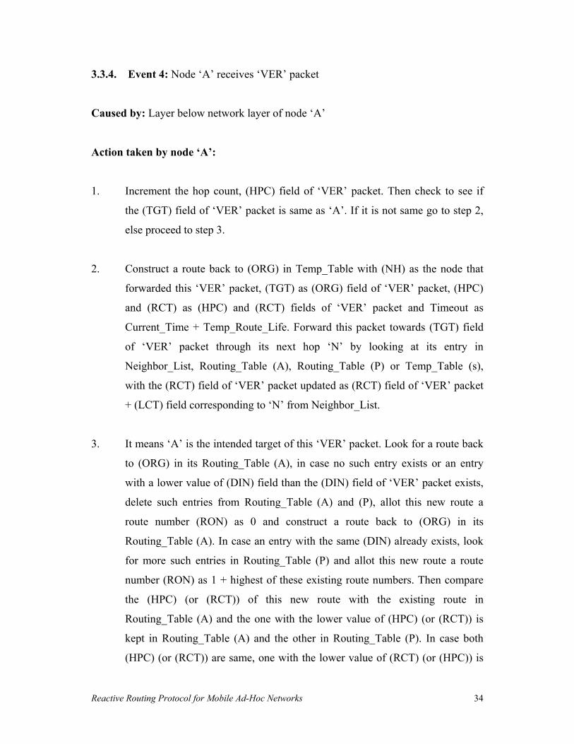
3.3.4. Event 4: Node �A� receives �VER� packet
Caused by: Layer below network layer of node �A�
Action taken by node �A�:
1. Increment the hop count, (HPC) field of �VER� packet. Then check to see if
the (TGT) field of �VER� packet is same as �A�. If it is not same go to step 2,
else proceed to step 3.
2. Construct a route back to (ORG) in Temp_Table with (NH) as the node that
forwarded this �VER� packet, (TGT) as (ORG) field of �VER� packet, (HPC)
and (RCT) as (HPC) and (RCT) fields of �VER� packet and Timeout as
Current_Time + Temp_Route_Life. Forward this packet towards (TGT) field
of �VER� packet through its next hop �N� by looking at its entry in
Neighbor_List, Routing_Table (A), Routing_Table (P) or Temp_Table (s),
with the (RCT) field of �VER� packet updated as (RCT) field of �VER� packet
+ (LCT) field corresponding to �N� from Neighbor_List.
3. It means �A� is the intended target of this �VER� packet. Look for a route back
to (ORG) in its Routing_Table (A), in case no such entry exists or an entry
with a lower value of (DIN) field than the (DIN) field of �VER� packet exists,
delete such entries from Routing_Table (A) and (P), allot this new route a
route number (RON) as 0 and construct a route back to (ORG) in its
Routing_Table (A). In case an entry with the same (DIN) already exists, look
for more such entries in Routing_Table (P) and allot this new route a route
number (RON) as 1 + highest of these existing route numbers. Then compare
the (HPC) (or (RCT)) of this new route with the existing route in
Routing_Table (A) and the one with the lower value of (HPC) (or (RCT)) is
kept in Routing_Table (A) and the other in Routing_Table (P). In case both
(HPC) (or (RCT)) are same, one with the lower value of (RCT) (or (HPC)) is

Reactive Routing Protocol for Mobile Ad-Hoc Networks 35
kept in Routing_Table (A). In case both (HPC) and (RCT) values are same, the
new route bearing higher route number (RON) is kept in Routing_Table (P).
The entry of new route in Routing_Table (A) or (P) is created with (DIN) as
(DIN) of �VER� packet, (RON) as just allotted route number to this route,
(ORG) as node �A� itself, (NH) as node �N� that forwarded this �VER� packet,
(NNH) initialised to NULL, (TGT) as (ORG) field of �VER� packet,
(HPC) and (RCT) as (HPC) and (RCT) fields of �VER� packet and Timeout as
Current_Time + Route_Life or Time as Current_Time. Send a �CON�
packet back to (ORG) field of �VER� packet through its next hop �N�, with
the fields of �CON� packet as
Packet Type, (TYP) = 4
Hop Count, (HPC) = initialized with 0
Route Cost, (RCT) = (LCT) field of Neighbor_List
corresponding to �N�
Dis_Identification No., (DIN) = (DIN) field of �VER� packet
Route No., (RON) = just allotted route no. to this route
Next to next hop towards Target, (NNT) = NULL
Originator Address, (ORG) = (ORG) field of �VER� packet
Target Address, (TGT) = (TGT) field of �VER� packet
Note: �A� and �N� mean IP address of nodes �A� and �N�.

Reactive Routing Protocol for Mobile Ad-Hoc Networks 36
3.3.5. Event 5: Node �A� receives �CON� packet
Caused by: Layer below network layer of node �A�
Action taken by node �A�:
1. Increment the hop count, (HPC) field of �CON� packet. Look for a matching
entry in its VER_Table with (DIN), (ORG) and (TGT) same as (DIN), (ORG)
and (TGT) fields of �CON� packet. If a matching entry is found delete this
entry from VER_Table. Then check to see if the (ORG) field of �CON� packet
is same as �A�. If it is not same go to step 2, else proceed to step 3.
2. Look for a route towards (ORG) and (TGT) in its Routing_Table (A), in case
no such entry exists or an entry with a lower value of (DIN) field than the
(DIN) field of �CON� packet exists, delete such entries from Routing_Table
(A) and (P) and construct a route towards (ORG) and (TGT) in Routing_Table
(A). (While deleting, entries for both (ORG) and (TGT) are deleted
simultaneously). In case an entry with the same (DIN) already exists in the
Routing_Table (A), compare the (HPC) (or (RCT)) of this route with the new
route, and the one with the lower value of (HPC) (or (RCT)) is kept in
Routing_Table (A) and the other in Routing_Table (P). In case both (HPC) (or
(RCT)) are same, one with the lower value of (RCT) (or (HPC)) is kept in
Routing_Table (A). In case both (HPC) and (RCT) values are same, one with
the lower (RON) is kept in Routing_Table (A) and the one with higher (RON)
in Routing_Table (P). When creating new entry, entries for both (ORG) and
(TGT) are created simultaneously. Entry of (ORG) in Routing_Table (A) or
(P) is created with (DIN) and (RON) as (DIN) and (RON) fields of �CON�
packet, (ORG) as (TGT) field of �CON� packet and (TGT) as (ORG) field of
�CON� packet, (NH), (HPC) and (RCT) as (NH), (HPC) and (RCT) fields of
Temp_Table entry corresponding to entry of (ORG), (NNH) as NULL and
Timeout as Current_Time + Route_Life or Time as Current_Time. Entry of

Reactive Routing Protocol for Mobile Ad-Hoc Networks 37
(TGT) in Routing_Table (A) or (P) is created with (DIN), (RON), (ORG),
(TGT), (HPC) and (RCT) as (DIN), (RON), (ORG), (TGT), (HPC) and (RCT)
fields of �CON� packet, (NH) as node that forwarded this �CON� packet,
(NNH) as (NNT) field of �CON� packet and Timeout as Current_Time +
Route_Life or Time as Current_Time. Then forward this �CON� packet
towards (ORG) through its next hop �N�, with the (NNT) field of �CON�
packet changed to the node that last forwarded this �CON� packet and (RCT)
field of �CON� packet updated as (RCT) field of �CON� packet + (LCT) field
corresponding to �N� from Neighbor_List. Also send an �ACK� packet back to
the node that forwarded this �CON� packet with the fields of �ACK� packet as
Packet Type, (TYP) = 5
Dis_Identification No., (DIN) = (DIN) field of �CON� packet
Route No., (RON) = (RON) field of �CON� packet
Next to next hop towards Originator, (NNO) = (NH) field of
Routing_Table for the entry of (ORG)
Originator Address, (ORG) = (ORG) field of �CON� packet
Target Address, (TGT) = (TGT) field of �CON� packet
3. Remove the entry coresponding to this (TGT) from DIS_Table and also free
the space of Temp_Table corresponding to this route discovery. If the space
permits it can store these routes of Temp_Table in its Routing_Table (P). Look
for a route to (TGT) in the Routing_Table (A), in case no such entry exists
enter the new route to (TGT) in the Routing_Table (A). In case an entry with
the same (DIN) exists compare the (HPC) (or (RCT)) of this route with the
new route and the one with the lower value of (HPC) (or (RCT)) is kept in
Routing_Table (A) and the other in Routing_Table (P). In case both (HPC) (or
(RCT)) are same, one with the lower value of (RCT) (or (HPC)) is kept in
Routing_Table (A). In case both (HPC) and (RCT) values are same, one with
lower (RON) is kept in Routing_Table (A) and the other in Routing_Table (P).
The entry of new route in Routing_Table (A) or (P) is created with (DIN),

Reactive Routing Protocol for Mobile Ad-Hoc Networks 38
(RON), (ORG), (TGT), (HPC) and (RCT) as (DIN), (RON), (ORG), (TGT),
(HPC) and (RCT) fields of �CON� packet, (NH) as node that forwarded this
�CON� packet, (NNH) as (NNT) field of �CON� packet and Timeout as
Current_Time + Route_Life or Time as Current_Time. Send an �ACK� packet
back to the node that forwarded this �CON� packet with the fields of �ACK�
packet as
Packet Type, (TYP) = 5
Dis_Identification No., (DIN) = (DIN) field of �CON� packet
Route No., (RON) = (RON) field of �CON� packet
Next to next hop towards Originator, (NNO) = NULL
Originator Address, (ORG) = (ORG) field of �CON� packet
Target Address, (TGT) = (TGT) field of �CON� packet
Note: �A� and �N� mean IP address of nodes �A� and �N�.
Reactive Routing Protocol for Mobile Ad-Hoc Networks 39
3.3.6. Event 6: Node �A� receives �ACK� packet
Caused by: Layer below network layer of node �A�
Action taken by node �A�:
1. Update the entry in Routing_Table (A) or (P) with the (DIN) and (RON) fields
same as (DIN) and (RON) fields of �ACK� packet and (ORG) field same as
(TGT) field of �ACK� packet and (TGT) field same as (ORG) field of �ACK�
packet, by setting the (NNH) field as (NNO) field of �ACK� packet.
Note: �A� means IP address of node �A�.

Reactive Routing Protocol for Mobile Ad-Hoc Networks 40
3.3.7. Event 7: Node �A� detects a break in its link to node �B�
Caused by: Layer below network layer of node �A�
Action taken by node �A�:
1. Consider each route in Routing_Table (A) that uses �B� as its next hop and for
each such route repeat the following steps.
2. Let target node of this route to be repaired be �T�, the corresponding originator
node be �O� and its next to next hop towards target be �C�. In case �C� is not
equal to NULL go to step 3. Else if �C� is not NULL it means �T� was next hop
of �A� i.e. �B� is same as �T�. Since link to �B� is currently broken, send an
�INV� packet back to �O� through its next hop by looking at its entry in the
Routing_Table (A) with the fields of �INV� packet as
Packet Type, (TYP) = 6
Invalid Type, (INT) = 1
Dis_Identification No., (DIN) = (DIN) field of route to be repaired
Route No., (RON) = (RON) field of route to be repaired
Sender of INV Packet, (SIN) = �A�
Originator Address, (ORG) = �O�
Target Address, (TGT) = �T�
3. Look for an entry of node �T� in the (NBR) field of Neighbor_List, in case no
matching entry is found go to step 4. Else if a matching entry is found make
(NH) field of route to be repaired as �T�, (NNH) as NULL, (HPC) as 1, (RCT)
as (LCT) field of Neighbor_List corresponding to �T� and Timeout as
Current_Time + Route_Life in the Routing_Table (A). Let (NH) field of
Routing_Table (A) corresponding to route towards �O� be �M�. Send �MOD�
packet to �T� with the fields of �MOD� packet as
Reactive Routing Protocol for Mobile Ad-Hoc Networks 41
Packet Type, (TYP) = 9
Hop Count, (HPC) = (HPC) field of Routing_Table (A)
corresponding to route towards �O�
Route Cost, (RCT) = (RCT) field of Routing_Table (A)
corresponding to route towards �O� + (LCT)
field of Neighbor_List corresponding to �T�
Dis_Identification No., (DIN) = (DIN) field of route to be repaired
Route No., (RON) = (RON) field of route to be repaired
Next hop towards Target, (NT) = �A�
Next to next hop towards Target, (NNT) = �M�
Originator Address, (ORG) = �T�
Target Address, (TGT) = �O�
Also send a �MOD� packet to �M� with the fields of �MOD� packet as
Packet Type, (TYP) = 9
Hop Count, (HPC) = 1
Route Cost, (RCT) = (LCT) field of Neighbor_List
corresponding to �T� + (LCT) field of
Neighbor_List corresponding to �M�
Dis_Identification No., (DIN) = (DIN) field of route to be repaired
Route No., (RON) = (RON) field of route to be repaired
Next hop towards Target, (NT) = �A�
Next to next hop towards Target, (NNT) = �T�
Originator Address, (ORG) = �O�
Target Address, (TGT) = �T�
4. Look for an entry in RPR_Table with the (DIN), (RON), (ORG) and (TGT)
fields same as (DIN), (RON), (ORG) and (TGT) fields of route to be repaired.
In case no matching entry is found proceed to step 5. Else if a matching entry
is found check to see if the Repair_Flag is set to �Yes� or �No�. If the

Reactive Routing Protocol for Mobile Ad-Hoc Networks 42
Repair_Flag is set to �Yes� it means route repair for this route is currently on so
these data packets are kept in the buffer. Else if the Repair_Flag is set to �No�
it means the route could not be repaired successfully earlier so these data
packets are discarded.
5. Make an entry in RPR_Table with (DIN), (RON), (ORG) and (TGT) as (DIN),
(RON), (ORG) and (TGT) fields of route to be repaired, Repair_Flag as �Yes�
and Timeout as Current_Time + Route_Repair_Life. Send a �RPR� packet to
all its neighbors �N� from Neighbor_List with the fields of �RPR� packet as
Packet Type, (TYP) = 7
Hop Count, (HPC) = (HPC) field of Routing_Table (A)
corresponding to route towards �O�
Route Cost, (RCT) = (RCT) field of Routing_Table (A)
corresponding to route towards �O� + (LCT)
field of Neighbor_List corresponding to �N�
Dis_Identification No., (DIN) = (DIN) field of route to be repaired
Route No., (RON) = (RON) field of route to be repaired
Repair_Originator Address, (RPO) = �A�
Repair_Target Address, (RPT) = �C�
Originator Address, (ORG) = (ORG) field of route to be repaired
Target Address, (TGT) = (TGT) field of route to be repaired
In case no �RCN� packet is received by �A� within a timeout period after
sending �RPR� packet update the corresponding entry in RPR_Table such that
set the Repair_Flag as �No� and set Timeout as Current_Time + Deletion_Life,
after which this entry is deleted from the RPR_Table. Send an �INV� packet
back to �O� through its next hop with the fields of �INV� packet as
Packet Type, (TYP) = 6
Invalid Type, (INT) = 1

Reactive Routing Protocol for Mobile Ad-Hoc Networks 43
Dis_Identification No., (DIN) = (DIN) field of route to be repaired
Route No., (RON) = (RON) field of route to be repaired
Sender of INV Packet, (SIN) = �A�
Originator Address, (ORG) = �O�
Target Address, (TGT) = �T�
Note: �A�, �B�, �C�, �M�, �N�, �O� and �T� mean IP address of nodes �A�, �B�, �C�, �M�,
�N�, �O� and �T�.

Reactive Routing Protocol for Mobile Ad-Hoc Networks 44
3.3.8. Event 8: Node �A� receives �INV� packet
Caused by: Layer below network layer of node �A�
Action taken by node �A�:
1. Look for the entry of now invalid route in the Routing_Table (A) with the
(DIN), (RON), (ORG) and (TGT) fields same as (DIN), (RON), (ORG) and
(TGT) fields of �INV� packet. Delete this route from Routing_Table (A) and
enter this route in Routing_Table (P) with Time as Current_Time �
2*Route_Life. If (ORG) field of �INV� packet is not same as �A�, forward this
packet towards (ORG) through its next hop by looking at its entry in
Routing_Table (A).
Note: �A� means IP address of node �A�.

Reactive Routing Protocol for Mobile Ad-Hoc Networks 45
3.3.9. Event 9: Node �A� receives �RPR� packet
Caused by: Layer below network layer of node �A�
Action taken by node �A�:
1. First of all increment the (HPC) field of �RPR� packet. Then check to see if
(RPT) field of �RPR� packet is same as �A�. If it is not same go to step 2, else
proceed to step 3.
2. Look for an entry of (RPT) field of �RPR� packet in the (NBR) field of
Neighbor_List. If a matching entry is found update the (RCT) field of �RPR�
packet as (RCT) field of �RPR� packet + (LCT) field of Neighbor_List
corresponding to (RPT) and forward this packet to (RPT) field of �RPR�
packet.
3. Look for an entry in its Routing_Table (A) with the (DIN) and (RON) fields
same as (DIN) and (RON) fields of �RPR� packet, (ORG) as (TGT) field of
�RPR� packet and (TGT) as (ORG) field of �RPR� packet. If a matching entry
is found update this entry such that make (NH) field of this route as the node
�N� that forwarded this packet, (NNH) as (RPO) field of �RPR� packet, (HPC)
and (RCT) fields as (HPC) and (RCT) fields of �RPR� packet. (Ignore all
subsequent �RPR� packets for the same route for a certain interval of time to
avoid duplication). Let (NH) field of Routing_Table (A) corresponding to
route towards (TGT) be �M�. Send a �RCN� packet to the node �N� with the
fields of �RCN� packet as
Packet Type, (TYP) = 8
Hop Count, (HPC) = (HPC) field of Routing_Table (A)
corresponding to route towards (TGT)
Reactive Routing Protocol for Mobile Ad-Hoc Networks 46
Route Cost, (RCT) = (RCT) field of Routing_Table (A)
corresponding to route towards (TGT) + (LCT)
field of Neighbor_List corresponding to �N�
Dis_Identification No., (DIN) = (DIN) field of �RPR� packet
Route No., (RON) = (RON) field of �RPR� packet
Repair_Originator Address, (RPO) = (RPO) field of �RPR� packet
Repair_Target Address, (RPT) = (RPT) field of �RPR� packet
Originator Address, (ORG) = (ORG) field of �RPR� packet
Target Address, (TGT) = (TGT) field of �RPR� packet
Next to next hop towards Target, (NNT) = �M�
Also send a �MOD� packet to �M� with the fields of �MOD� packet as
Packet Type, (TYP) = 9
Hop Count, (HPC) = (HPC) field of �RPR� packet
Route Cost, (RCT) = (RCT) field of �RPR� packet +
(LCT) field of Neighbor_List corresponding to �M�
Dis_Identification No., (DIN) = (DIN) field of �RPR� packet
Route No., (RON) = (RON) field of �RPR� packet
Next hop towards Target, (NT) = �A�
Next to next hop towards Target, (NNT) = �N�
Originator Address, (ORG) = (TGT) field of �RPR� packet
Target Address, (TGT) = (ORG) field of �RPR� packet
Note: �A�, �M� and �N� mean IP address of nodes �A�, �M� and �N�.

Reactive Routing Protocol for Mobile Ad-Hoc Networks 47
3.3.10. Event 10: Node �A� receives �RCN� packet
Caused by: Layer below network layer of node �A�
Action taken by node �A�:
1. First of all increment the (HPC) field of �RPR� packet. Then check to see if
(RPO) field of �RCN� packet is same as �A�. If it is not same go to step 2, else
proceed to step 3.
2. Enter a route towards (TGT) field of �RCN� packet in its Routing_Table (A)
with (HPC), (RCT), (DIN), (RON), (ORG) and (TGT) as (HPC), (RCT),
(DIN), (RON), (ORG) and (TGT) fields of �RCN� packet, (NH) as the node
that forwarded this �RCN� packet, (NNH) as (NNT) field of �RCN� packet and
Timeout as Current_Time + Route_Life. Also enter a route towards (ORG)
field of �RCN� packet in Routing_Table (A) with (DIN) and (RON) as (DIN)
and (RON) fields of �RCN� packet, (ORG) as (TGT) field of �RCN� packet and
(TGT) as (ORG) field of �RCN� packet. Forward this packet to (RPO) field of
�RCN� packet with the (RCT) field of �RCN� packet updated as (RCT) field of
�RCN� packet + (LCT) field of Neighbor_List corresponding to (RPO) and
(NNT) field of �RCN� packet updated as the node that forwarded this �RCN�
packet.
3. Delete the entry in its RPR_Table with the (DIN), (RON), (ORG) and (TGT)
fields same as (DIN), (RON), (ORG) and (TGT) fields of �RCN� packet.
Update the entry in its Routing_Table (A) with the (DIN), (RON), (ORG) and
(TGT) fields same as (DIN), (RON), (ORG) and (TGT) fields of �RCN� packet
such that make (NH) as the node that forwarded this �RCN� packet, (HPC) and
(RCT) as (HPC) and (RCT) fields of �RCN� packet and Timeout as
Current_Time + Route_Life. Let node �M� be the (NH) field of Routing_Table

Reactive Routing Protocol for Mobile Ad-Hoc Networks 48
(A) corresponding to route towards (ORG). Send a �MOD� packet to the node
�N� that forwarded this �RCN� packet with the fields of �MOD� packet as
Packet Type, (TYP) = 9
Hop Count, (HPC) = (HPC) field of Routing_Table (A)
corresponding to route towards (ORG)
Route Cost, (RCT) = (RCT) field of Routing_Table (A)
corresponding to route towards (ORG) + (LCT)
field of Neighbor_List corresponding to �N�
Dis_Identification No., (DIN) = (DIN) field of �RCN� packet
Route No., (RON) = (RON) field of �RCN� packet
Next hop towards Target, (NT) = �A�
Next to next hop towards Target, (NNT) = �M�
Originator Address, (ORG) = (TGT) field of �RCN� packet
Target Address, (TGT) = (ORG) field of �RCN� packet
Also send a �MOD� packet to �M� with the fields of �MOD� packet as
Packet Type, (TYP) = 9
Hop Count, (HPC) = (HPC) field of �RCN� packet
Route Cost, (RCT) = (RCT) field of �RCN� packet +
(LCT) field of Neighbor_List corresponding to �M�
Dis_Identification No., (DIN) = (DIN) field of �RCN� packet
Route No., (RON) = (RON) field of �RCN� packet
Next hop towards Target, (NT) = �A�
Next to next hop towards Target, (NNT) = �N�
Originator Address, (ORG) = (ORG) field of �RCN� packet
Target Address, (TGT) = (TGT) field of �RCN� packet
Note: �A�, �M� and �N� mean IP address of nodes �A�, �M� and �N�.

Reactive Routing Protocol for Mobile Ad-Hoc Networks 49
3.3.11. Event 11: Node �A� receives �MOD� packet
Caused by: Layer below network layer of node �A�
Action taken by node �A�:
1. Update the entry in Routing_Table (A) with (DIN), (RON), (ORG) and (TGT)
fields same as (DIN), (RON), (ORG) and (TGT) fields of �MOD� packet such
that make (HPC) as 1 + (HPC) field of �MOD� packet, (RCT) as (RCT) field of
�MOD� packet, (NH) as (NT) field of �MOD� packet, (NNH) as (NNT) field of
�MOD� packet and Timeout as Current_Time + Route_Life.
Note: �A� means IP address of node �A�.
Reactive Routing Protocol for Mobile Ad-Hoc Networks 50
Chapter - 4
Performance Evaluation _____________________________________________________________________
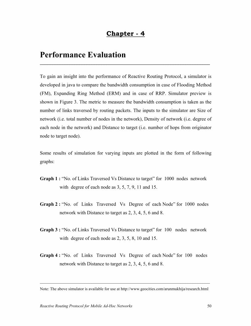
To gain an insight into the performance of Reactive Routing Protocol, a simulator is
developed in java to compare the bandwidth consumption in case of Flooding Method
(FM), Expanding Ring Method (ERM) and in case of RRP. Simulator preview is
shown in Figure 3. The metric to measure the bandwidth consumption is taken as the
number of links traversed by routing packets. The inputs to the simulator are Size of
network (i.e. total number of nodes in the network), Density of network (i.e. degree of
each node in the network) and Distance to target (i.e. number of hops from originator
node to target node).
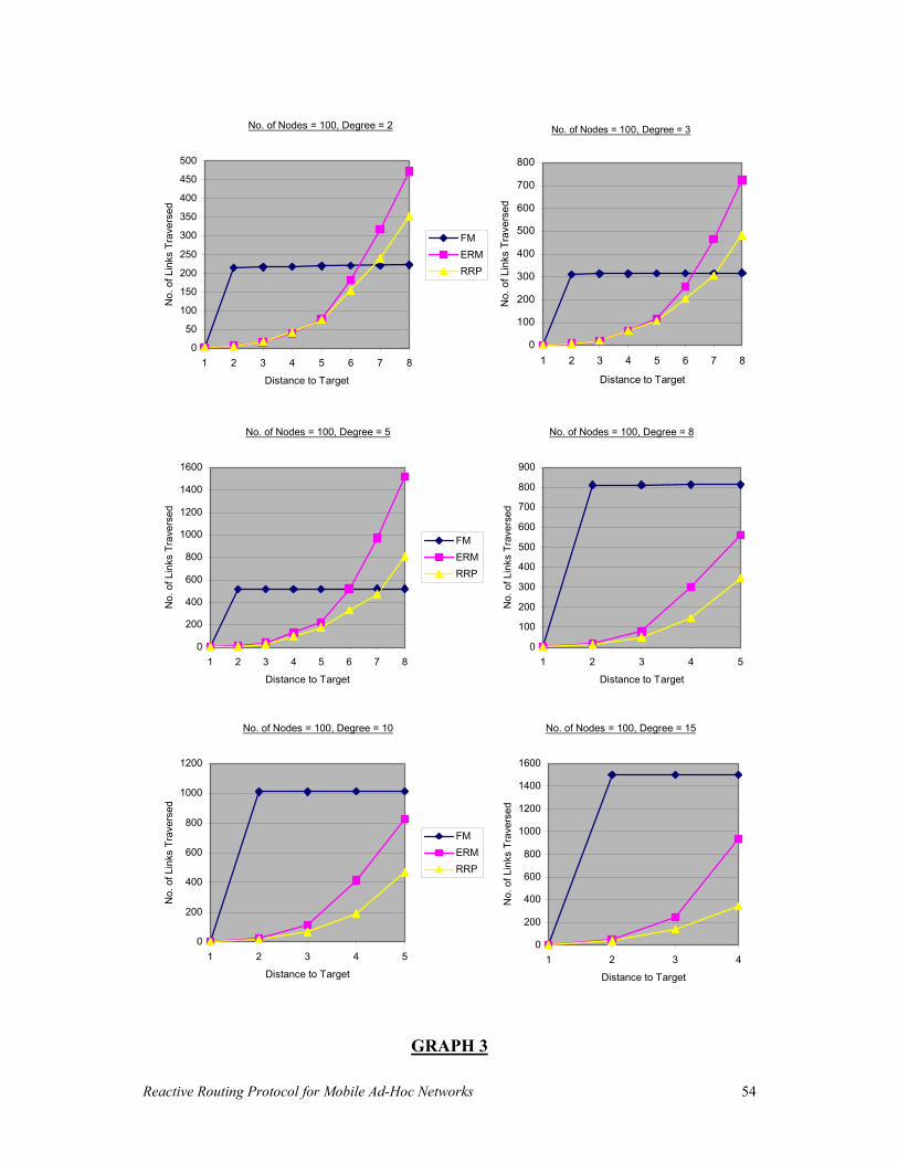
Some results of simulation for varying inputs are plotted in the form of following
graphs:
Graph 1 : �No. of Links Traversed Vs Distance to target� for 1000 nodes network
with degree of each node as 3, 5, 7, 9, 11 and 15.
Graph 2 : �No. of Links Traversed Vs Degree of each Node� for 1000 nodes
network with Distance to target as 2, 3, 4, 5, 6 and 8.
Graph 3 : �No. of Links Traversed Vs Distance to target� for 100 nodes network
with degree of each node as 2, 3, 5, 8, 10 and 15.
Graph 4 : �No. of Links Traversed Vs Degree of each Node� for 100 nodes
network with Distance to target as 2, 3, 4, 5, 6 and 8.
_____________________________________________________________________Note: The above simulator is available for use at http://www.geocities.com/arunmukhija/research.html

Reactive Routing Protocol for Mobile Ad-Hoc Networks 51
Figure 3: Preview of Simulator.

Reactive Routing Protocol for Mobile Ad-Hoc Networks 52
GRAPH 1
No. of Nodes = 1000, Degree = 3
0
1000
2000
3000
4000
5000
6000
1 2 3 4 5 6 7 8
Distance to Target
No.
of L
inks
Tra
vers
ed
FMERMRRP
No. of Nodes = 1000, Degree = 5
0
1000
2000
3000
4000
5000
6000
7000
8000
1 2 3 4 5 6 7 8
Distance to Target
No.
of L
inks
Tra
vers
ed
No. of Nodes = 1000, Degree = 7
0
2000
4000
6000
8000
10000
12000
1 2 3 4 5 6 7 8
Distance to Target
No.
of L
inks
Tra
vers
ed
FMERMRRP
No. of Nodes = 1000, Degree = 9
0
2000
4000
6000
8000
10000
12000
14000
16000
1 2 3 4 5 6 7 8
Distance to Target
No.
of L
inks
Tra
vers
ed
No. of Nodes = 1000, Degree = 11
0
5000
10000
15000
20000
25000
1 2 3 4 5 6 7 8
Distance to Target
No.
of L
inks
Tra
vers
ed
FMERMRRP
No. of Nodes = 1000, Degree = 15
0
5000
10000
15000
20000
25000
30000
35000
1 2 3 4 5 6 7 8
Distance to Target
No.
of L
inks
Tra
vers
ed

Reactive Routing Protocol for Mobile Ad-Hoc Networks 53
GRAPH 2
No. of Nodes = 1000, Distance to Target = 2
0
2000
4000
6000
8000
10000
12000
14000
16000
3 5 7 9 11 13 15
Degree of each Node
No.
of L
inks
Tra
vers
ed
FMERMRRP
No. of Nodes = 1000, Distance to Target = 3
0
2000
4000
6000
8000
10000
12000
14000
16000
3 5 7 9 11 13 15
Degree of each Node
No.
of L
inks
Tra
vers
ed
No. of Nodes = 1000, Distance to Target = 4
0
2000
4000
6000
8000
10000
12000
14000
16000
3 5 7 9 11 13 15
Degree of each Node
No.
of L
inks
Tra
vers
ed
FMERMRRP
No. of Nodes = 1000, Distance to Target = 5
0
2000
4000
6000
8000
10000
12000
14000
16000
3 5 7 9 11 13 15
Degree of each Node
No.
of L
inks
Tra
vers
ed
No. of Nodes = 1000, Distance to Target = 6
0
2000
4000
6000
8000
10000
12000
14000
16000
3 5 7 9 11 13 15
Degree of each Node
No.
of L
inks
Tra
vers
ed
FMERMRRP
No. of Nodes = 1000, Distance to Target= 8
0
5000
10000
15000
20000
25000
30000
35000
3 5 7 9 11 13 15
Degree of each Node
No.
of L
inks
Tra
vers
ed
Reactive Routing Protocol for Mobile Ad-Hoc Networks 54
GRAPH 3
No. of Nodes = 100, Degree = 2
0
50
100
150
200
250
300
350
400
450
500
1 2 3 4 5 6 7 8
Distance to Target
No.
of L
inks
Tra
vers
ed
FMERMRRP
No. of Nodes = 100, Degree = 5
0
200
400
600
800
1000
1200
1400
1600
1 2 3 4 5 6 7 8
Distance to Target
No.
of L
inks
Tra
vers
ed
FMERMRRP
No. of Nodes = 100, Degree = 8
0
100
200
300
400
500
600
700
800
900
1 2 3 4 5
Distance to Target
No.
of L
inks
Tra
vers
ed
No. of Nodes = 100, Degree = 10
0
200
400
600
800
1000
1200
1 2 3 4 5
Distance to Target
No.
of L
inks
Tra
vers
ed
FMERMRRP
No. of Nodes = 100, Degree = 3
0
100
200
300
400
500
600
700
800
1 2 3 4 5 6 7 8
Distance to Target
No.
of L
inks
Tra
vers
ed
No. of Nodes = 100, Degree = 15
0
200
400
600
800
1000
1200
1400
1600
1 2 3 4
Distance to Target
No.
of L
inks
Tra
vers
ed

Reactive Routing Protocol for Mobile Ad-Hoc Networks 55
GRAPH 4
No. of Nodes = 100, Distance to Target = 3
0
200
400
600
800
1000
1200
1400
1600
1 3 5 7 9 11 13 15
Degee of each Node
No.
of L
inks
Tra
vers
ed
No. of Nodes = 100, Distance to Target = 4
0
200
400
600
800
1000
1200
1400
1600
1 3 5 7 9 11 13 15
Degree of each Node
No.
of L
inks
Tra
vers
ed
FMERMRRP
No. of Nodes = 100, Distance to Target = 5
0
200
400
600
800
1000
1200
1 2 3 4 5 6 7 8 9 10
Degree of each Node
No.
of L
inks
Tra
vers
ed
No. of Nodes = 100, Distance to Target = 6
0
100
200
300
400
500
600
700
800
900
1000
1 2 3 4 5 6 7
Degree of each Node
No.
of L
inks
Tra
vers
ed
FMERMRRP
No. of Nodes = 100, Distance to Target = 2
0
200
400
600
800
1000
1200
1400
1600
1 3 5 7 9 11 13 15
Degree of each Node
No.
of L
inks
Tra
vers
ed
FMERMRRP
No. of Nodes = 100, Distance to Target = 8
0
200
400
600
800
1000
1200
1400
1600
1 2 3 4 5
Degree of each Node
No.
of L
inks
Tra
vers
ed
Reactive Routing Protocol for Mobile Ad-Hoc Networks 56
Some of the observations from the graphs presented are as follows:
Observations from Graph 1 : RRP is found to be much more efficient than FM for
low distance to target, but this difference is diminished as distance to target increases.
Such that for a low degree of each node (=3) and high distance to target (=8), RRP is
actually less efficient than FM. However for higher degree of each node RRP continues
to be most efficient. RRP is more efficient than ERM for all the cases and this
difference is more and more evident as the degree of each node is increased and as the
distance to target is increased. Similar observations can be drawn from Graph 3 as
well.
Observations from Graph 2 : Both RRP and ERM are much more efficient than FM
for low distance to target. However this difference is reduced as distance to target is
increased. In face ERM is actually less efficient than FM when distance to target is
quite high (=8). RRP continues to be more efficient than ERM and the difference is
much higher for higher degree of each node and for higher distance to target. Similar
observations hold good for Graph 4 as well.
______________________________________________________________________Note: Efficiency here means bandwidth efficiency and is measured in terms of number of links traversed.
Reactive Routing Protocol for Mobile Ad-Hoc Networks 57
Chapter - 5
Further Optimizations _____________________________________________________________________
A number of further optimizations are possible in addition to the basic operation of
Reactive Routing Protocol described in Chapters 2 and 3. These optimizations which
may result in the improved performance of protocol are discussed as under.
• Prefer to include stable neighbor nodes in a prospective route during route
discovery process. As the routes composed of stable nodes obviously tend to be
more stable and thus result in the reduced routing overhead during route
maintenance phase. The metric to measure Stability_Value of a neighbor node can
be taken as (Current_Time � Time the neighbor was first discovered). Preference
to a stable neighbor node can be given in the following ways.
1. Only the neighbor nodes having Stability_Value greater than some threshold
value are considered to be included in the route response packet.
2. Stability_Value can be made a part of link cost by some formula so that links
with lower transmission time and those towards more stable neighbor nodes
tend to preferred. Since in the basic operation of protocol we prefer routes
composed of lower link costs, the new formula for link cost to a neighbor node
would be directly proportional to the transmission time over that link and
inversely proportional to the Stability_Value of neighbor node. Different
weights can be assigned to the above two component values and the trade-off
is decided depending upon the preference for a more stable route or for a route
with lowest transmission time.
• In the basic operation of protocol we have described link cost to a neighbor node
as the time required to traverse the link to this neighbor node. This link cost is

Reactive Routing Protocol for Mobile Ad-Hoc Networks 58
measured as part of the neighbor discovery process which is done quite frequently
after regular short intervals of time. At some point in time the link cost may reflect
an instantaneous peak in the transmission time due to a temporary increase in load
on this link. This instantaneous peak in the link cost may send in wrong signals
about the high congestion on this link, which is otherwise quite a congestion free
link. In order to enable link cost to reflect the correct congestion data on this link
over a large interval of time and to compensate for the occasional peaks in its
value, the link cost should be taken as the average of old value of link cost and
newly observed value of link cost. Again different weights can be assigned to
above two component values in computing the average depending on our
preference to give more significance to the currently observed congestion data or
the congestion data over a large interval of time.
• If a node �A� experiences congestion on its link to node �B�, it can adventure to
initiate the Surroundings Repair Method for this link in the hope to find an
alternate route which is less congested and hence faster than the present route.
Thus the Surroundings Repair Method can be initiated not just in case of link
failures but also in case of congested links.
Reactive Routing Protocol for Mobile Ad-Hoc Networks 59
Chapter - 6
Future Work _____________________________________________________________________
Future work on this project involves the following.
• Security considerations and the problem of non cooperative nodes are not
addressed here and the future work may be the addressal of these issues.
• Interconnection of mobile ad-hoc network with an infrastructure based network
may also be part of the future work.
• Links between two nodes are assumed to be symmetric i.e. bidirectional. This
assumption poses no problems in the working of protocol because if a
unidirectional link is encountered it can not be used due to its inability to forward
response packet in the reverse direction of discovery packet, and thus a
unidirectional link will not be included in the formation of any route. The future
work may be to identify some way of utilizing unidirectional links in the
formation of routes.

Reactive Routing Protocol for Mobile Ad-Hoc Networks 60
Chapter - 7
Conclusion _____________________________________________________________________
This thesis has presented a new on-demand routing protocol called �Reactive Routing
Protocol� for mobile ad-hoc networks, to provide a bandwidth efficient routing
solution for such networks. Route Discovery part of this protocol is managed by
Incremental Search Method which is more bandwidth efficient than conventional
broadcast based methods used for route discovery in other protocols suggested for
MANETs. Bandwidth efficiency of Incremental Search Method is primarily due to
reduced number of links traversed for the same routes discovered as compared to the
broadcast based methods. This efficiency is further augmented by the supplementary
routing information available to the originator node and other intermediate nodes as an
additional benefit of route discovery process, which helps in expediting future route
discoveries. Route Maintenance function of this protocol is taken care of by
Surroundings Repair Method, which stimulates each node to repair and maintain its
local surroundings to ensure the connectivity of each route passing through it. Thus
the Surroundings Repair Method also helps in reducing routing overhead and thus
adds to the overall bandwidth efficiency of this protocol. The bandwidth efficiency
characteristic of this protocol is well supported by the simulation results presented.

Reactive Routing Protocol for Mobile Ad-Hoc Networks 61
References
[1] S. Corson and J. Macker, �Mobile Ad-Hoc Networking (MANET): Routing
Protocol Performance Issues and Evaluation Considerations�, IETF RFC 2501,
January 1999.
[2] Elizabeth M. Royer and C-K Toh, �A Review of Current Routing Protocols for
Ad-Hoc Mobile Wireless Networks�, IEEE Personal Communications, Vol. 6,
No. 2, pp. 46-55, April 1999.
[3] David B. Johnson, �Routing in Ad Hoc Networks of Mobile Hosts�, Proceedings
of IEEE Workshop on Mobile Computing Systems and Applications, December
1994.
[4] Andrew S. Tanenbaum, �Computer Networks�, Third Edition, Prentice Hall of
India, Chapter 5, pp. 339-478, October 2000.
[5] J.-P. Hubaux, Th. Gross, J.-Y. Le Boudec and M. Vetterli, �Towards Self-
Organized Mobile Ad Hoc Networks: The Terminodes Project�, IEEE
Communications Magazine, January 2001.
[6] Charles E. Perkins and Pravin Bhagwat, �Highly Dynamic Destination-
Sequenced Distance-Vector Routing (DSDV) for Mobile Computers�, Computer
Communications Review, pp. 234-244, October 1994.
[7] Atsushi Iwata, Ching-Chuan Chiang, Guangyu Pei, Mario Gerla and Tsu-Wei
Chen, �Scalable Routing Strategies for Ad Hoc Wireless Networks�, IEEE
Journal on Selected Areas in Communications, Special Issue on Ad-Hoc
Networks, pp. 1369-79, August 1999.

Reactive Routing Protocol for Mobile Ad-Hoc Networks 62
[8] Shree Murthy and J. J. Garcia-Luna-Aceves, �An Efficient Routing Protocol for
Wireless Networks�, ACM Mobile Networks and Applications Journal, Special
Issue on Routing in Mobile Communication Networks, pp. 183-197, October
1996.
[9] Shree Murthy and J. J. Garcia-Luna-Aceves, �A Routing Protocol for Packet
Radio Networks�, Proceedings of MOBICOM�95, pp. 86-95.
[10] Ching-Chuan Chiang, Hsiao-Kuang Wu, Winston Liu, Mario Gerla, �Routing in
Clustered Multihop, Mobile Wireless Networks with Fading Channel�,
Proceedings of IEEE SICON�97, pp. 197-211, April 1997.
[11] Tsu-Wei Chen and Mario Gerla, �Global State Routing: A New Routing Scheme
for Ad-Hoc Wireless Networks�, Proceedings of IEEE ICC�98.
[12] David B. Johnson and David A. Maltz, �Dynamic Source Routing in Ad-Hoc
Wireless Networks�, Mobile Computing, edited by Tomasz Imielinski and Hank
Korth, Kluwer Academic Publishers, Chapter 5, pp. 153-181, 1996.
[13] David B. Johnson, David A. Maltz, Yih-Chun Ho and Jorjeta G. Jetcheva, �The
Dynamic Source Routing Protocol for Mobile Ad-Hoc Networks�, IETF Internet
Draft draft-ietf-manet-dsr-05.txt, March 2001 (Work in Progress).
[14] David A. Maltz, Josh Broch, Jorjeta Jetcheva and David B. Johnson, �The Effects
of On-Demand Behavior in Routing Protocols for Multi-Hop Wireless Ad Hoc
Networks�, IEEE Journal on Selected Areas in Communications, Special Issue on
Mobile And Wireless Networks, August 1999.
[15] Charles E. Perkins and Elizabeth M. Royer, �Ad Hoc On-Demand Distance
Vector Routing�, Proceedings of 2nd IEEE Workshop on Mobile Computing
Systems and Applications, February 1999.

Reactive Routing Protocol for Mobile Ad-Hoc Networks 63
[16] Charles E. Perkins, Elizabeth M. Royer and Samir R. Das, �Ad Hoc On-
Demand Distance Vector (AODV) Routing�, IETF Internet Draft draft-ietf-
manet-aodv-08.txt, March 2001 (Work in Progress).
[17] Vincent D. Park and M. Scott Corson, �A Highly Adaptive distributed Routing
Algorithm for Mobile Wireless Networks�, Proceedings of INFOCOM�97, April
1997.
[18] V. Park and S. Corson, �Temporally-Ordered Routing Algorithm (TORA)
Version 1 Functional Specification�, IETF Internet Draft draft-ietf-manet-tora-
spec-04.txt, July 2001 (Work in Progress).
[19] Chai-Keong Toh, �A Novel Distributed Routing Protocol To Support Ad-Hoc
Mobile Computing�, Proceedings of 1996 IEEE Fifteenth Annual International
Phoenix Conference on Computers and Communications, pp. 480-486, March
1996.
[20] Zygmunt J. Haas, �A New Routing Protocol for The Reconfigurable Wireless
Networks�, Proceedings of IEEE International Conference on Universal Personal
Communication (ICUPC�97).

Reactive Routing Protocol for Mobile Ad-Hoc Networks 64
Appendix
A.1. Terminology Used
Node: A MANET router that implements Reactive Routing Protocol and is
identified by a unique IP address.
Link: A logical connection between two nodes, such that these nodes can
communicate with each other directly without the need of any
intermediate node.
Neighbor: Two nodes are said to be neighbors if they are within each others
communication range i.e. a link exists between them.
Topology: Described by a random graph whose vertices represent the set of nodes
and edges represent the set of links between nodes.
Route: A route from node �a� to node �b� is a sequence of links required to be
traversed in a fixed order by a packet, in order to reach from node �a� to
node �b�.
Hop: A link required to be traversed by a data or control packet . Hop count
of a route is equal to number of links composing the route.
Active Route: A route that has been used to forward data packet within last
�Route_Life� interval of time.
Passive Route: A route that has not been used to forward data packet within last
�Route_Life� interval of time.

Reactive Routing Protocol for Mobile Ad-Hoc Networks 65
A.2. List of Acronyms
ABR Associativity Based Routing
AODV Ad Hoc On-Demand Distance Vector Routing
CGSR Clusterhead Gateway Switch Routing Protocol
DSDV Highly Dynamic Destination-Sequenced Distance-Vector Routing
DSR Dynamic Source Routing Protocol
FSR Fisheye State Routing
GSR Global State Routing
ISM Incremental Search Method
MANET Mobile Ad-Hoc Network
RRP Reactive Routing Protocol
SRM Surroundings Repair Method
TORA Temporally-Ordered Routing Algorithm
WRP Wireless Routing Protocol
ZRP Zone Routing Protocol