RE7-13 - iccsafe.org · RE7-13 . R302.1 (IRC N1101.11 ... Mandatory construction document...
377
RE7-13 R302.1 (IRC N1101.11) Proposed Change as Submitted Proponent: Jerry Anderson, City of Overland Park, KS, representing self ([email protected]) Revise as follows: R302.1 (N1101.11) Interior design conditions. The interior design temperatures used for heating and cooling load calculations shall be in accordance with ACCA Manual J. a maximum of 72 0 F (22 0 C) for heating and minimum of 75 0 F (24 0 C) for cooling. Reason: The purpose of this code change is to allow some flexibility in design conditions. There is no valid reason for the code to specify exact temperatures for interior design. Interior design conditions are all about comfort. The 72 degree temperature for heating and the 75 degree temperature for cooling are simply design temps where most people are comfortable, but comfort is dependent on physical attributes of individuals (age, sex, weight, metabolism, etc). If someone wishes to design a home or residential facility with different design conditions they should be allowed to do so. For example a group home being constructed for the elderly in accordance with the IRC provisions may wish to have different interior design temperatures for heating. The standard would allow for different design temperatures because it views the 72 degree and 75 degree marks as target values. Cost Impact: The code change proposal will not increase the cost of construction. R302.1-EC-ANDERSON.doc Committee Action Hearing Results Committee Action: Disapproved Committee Reason: ACCA Manual J gives a range of design conditions which are too broad a range to standardize the loads. Assembly Action: None Individual Consideration Agenda This item is on the agenda for individual consideration because a public comment was submitted. Public Comment: Gerald Anderson, City of Overland Park, representing self, requests Approval as Submitted. Commenter’s Reason: The purpose of this code change is to allow some flexibility in design conditions. There is no valid reason for the code to specify exact temperatures for interior design. Interior design conditions are all about comfort. The 72 degree temperature for heating and the 75 degree temperature for cooling are simply design temps where most people are comfortable, but comfort is dependent on physical attributes of individuals (age, sex, weight, metabolism, etc.). If someone wishes to design a home for residential facility with different design conditions they should be allowed to do so. For example a group home being constructed for elderly in accordance with the IRC provisions may wish to have different interior design temperatures for heating. The standard would allow for different design temperatures because it views the 72 degree and 75 degree marks as target values. RE7-13 Final Action: AS AM AMPC D 2013 ICC PUBLIC COMMENT AGENDA Page 792
Transcript of RE7-13 - iccsafe.org · RE7-13 . R302.1 (IRC N1101.11 ... Mandatory construction document...

RE7-13 R302.1 (IRC N1101.11)
Proposed Change as Submitted Proponent: Jerry Anderson, City of Overland Park, KS, representing self ([email protected]) Revise as follows: R302.1 (N1101.11) Interior design conditions. The interior design temperatures used for heating and cooling load calculations shall be in accordance with ACCA Manual J. a maximum of 720F (220C) for heating and minimum of 750F (240C) for cooling. Reason: The purpose of this code change is to allow some flexibility in design conditions. There is no valid reason for the code to specify exact temperatures for interior design. Interior design conditions are all about comfort. The 72 degree temperature for heating and the 75 degree temperature for cooling are simply design temps where most people are comfortable, but comfort is dependent on physical attributes of individuals (age, sex, weight, metabolism, etc). If someone wishes to design a home or residential facility with different design conditions they should be allowed to do so. For example a group home being constructed for the elderly in accordance with the IRC provisions may wish to have different interior design temperatures for heating. The standard would allow for different design temperatures because it views the 72 degree and 75 degree marks as target values. Cost Impact: The code change proposal will not increase the cost of construction.
R302.1-EC-ANDERSON.doc
Committee Action Hearing Results Committee Action: Disapproved Committee Reason: ACCA Manual J gives a range of design conditions which are too broad a range to standardize the loads. Assembly Action: None
Individual Consideration Agenda
This item is on the agenda for individual consideration because a public comment was submitted. Public Comment: Gerald Anderson, City of Overland Park, representing self, requests Approval as Submitted. Commenter’s Reason: The purpose of this code change is to allow some flexibility in design conditions. There is no valid reason for the code to specify exact temperatures for interior design. Interior design conditions are all about comfort. The 72 degree temperature for heating and the 75 degree temperature for cooling are simply design temps where most people are comfortable, but comfort is dependent on physical attributes of individuals (age, sex, weight, metabolism, etc.). If someone wishes to design a home for residential facility with different design conditions they should be allowed to do so. For example a group home being constructed for elderly in accordance with the IRC provisions may wish to have different interior design temperatures for heating. The standard would allow for different design temperatures because it views the 72 degree and 75 degree marks as target values. RE7-13 Final Action: AS AM AMPC D
2013 ICC PUBLIC COMMENT AGENDA Page 792
RE8-13 R202 (NEW) (IRC N1101.9 (NEW)), R304 (NEW) (IRC N1102.16 (NEW))
Proposed Change as Submitted Proponent: Chris Mathis, Mathis Consulting Company, representing self Add new text as follows: R304 (N1102.16) SOLAR READY ZONE. R304.1 (N1102.16.1) General. All new detached one- and two-family dwellings, and multiple single family dwellings having roofs oriented between 110 degrees and 270 degrees of true north shall comply with sections R304.2 through R304.8. R304.2 (N1102.16.2) Mandatory construction document requirements for solar ready zone. Construction documents for new detached one- and two-family dwellings, and multiple single family dwellings having roofs oriented between 110 degrees and 270 degrees of true north shall indicate the solar ready zone. R304.3 (N1102.16.3) Solar ready zone area. The total solar ready zone area shall be no less than 300 square feet exclusive of mandatory access or set back areas required by the International Fire Code. New detached one- and two-family dwellings, and multiple single family dwellings with three stories or more and with a total floor area less than or equal to 2000 square feet shall have a solar ready zone area no less than 150 square feet. The solar ready zone shall be comprised of areas that have no dimension less than five feet and are no less than 80 square feet exclusive of mandatory access or set back areas as required by the International Fire Code.
Exceptions:
1. New buildings with a permanently installed on-site renewable energy system. 2. Roof areas in shade more than 70 percent of the time.
R304.4 (N1102.16.4) Obstructions. Solar ready zones shall be free from obstructions, including but not limited to vents, chimneys, and roof mounted equipment. R304.5 (N1102.16.5) Roof load documentation. The structural design loads for roof dead load and roof live load shall be clearly indicated on the construction documents. R304.6 (N1102.16.6) Interconnection pathway. Construction documents shall indicate the installed pathways for conduit, pre-wiring, pre-plumbing, or plumbing chase from the solar ready zone to the electrical service panel or service hot water system. R304.7 (N1102.16.7) Electrical service reserved space. The main electrical service panel shall have a minimum busbar rating of 200 amps, shall have reserved space to allow installation of a dual pole circuit breaker for future solar electric installation, and shall be labeled “For Future Solar Electric”. The reserved space shall be positioned at the opposite (load) end from the input feeder location or main circuit location.
Exception: Building projects with installed pre-plumbing or plumbing chase from the solar ready zone to reserved space at the water heating system.
R304.8 (N1102.16.8) Construction documentation. A copy of the construction documents indicating the solar ready zone and other requirements of this section shall be posted near the electrical panel, water heater, or other conspicuous location in the building.
2013 ICC PUBLIC COMMENT AGENDA Page 793

Add new definition as follows:
IECC SECTION R202 (IRC N1101.9) GENERAL DEFINITIONS
SOLAR READY ZONE. A section or sections of the roof or building overhang designated and reserved for the future installation of a solar electric or solar thermal system. Reason: This proposal is intended to support future potential improvements for detached one- and two-family dwellings, and multiple single family dwellings for solar electric and solar thermal systems. The proposed language follows similar language from code adoptions by local municipalities in Tucson, AZ, Boulder, CO, and from the 2013 California Title 24 building code.
This proposal is intended to identify the areas of a residential building roof, called the solar ready zone, for potential future installation of renewable energy systems. This proposal requires documenting necessary solar ready information on the plans, some of which may already be required in permit construction requirements. This proposal also requires the builder to post specific information about the home for use by the homeowner(s).
This proposal requires the installation of chase, conduit, pre wiring, or pre-plumbing. It does not require any specific physical orientation of the residential building. It does not require any increased load capacities for residential roofing systems. When considered at the time of design, this proposal needs not increase the cost of construction, though will add a small, recoverable cost in many cases.
The documentation of solar ready zones and roof load calculations (already performed during the design phase) will assist building departments, as well as any future solar contractors seeking to install renewable energy systems on the roof. The builder/designer is knowledgeable on the intricacies of each model and plan, and easily can identify unobstructed roof areas, as well as spaces where conduit, wiring, and plumbing can be routed from the roof to the respective utility areas. This will save building departments and solar designers time and effort when installing future solar systems.
Upfront costs of renewable energy systems frequently are the largest deterrent to installation. Without preparation at the time of construction, solar installation may not even be technically possible. If a homeowner wishes to install a solar energy system later, this preparation can save thousands of dollars in labor, installation, design, and integration of the solar system into the house. Solar ready design can decrease the payback period tremendously. This is critical as these systems continue to become more cost effective and incentives are more readily available. In the instance that the initial homeowner does not intend to install a solar system, making the building solar ready increases the resale value of the home and the cost can be recovered.
Many building departments have been mandated by local regulations to accelerate permits and inspections for solar installation. Having important information and documentation available to the building department, solar contractor, and homeowner will assist in supporting the accelerated working environment many municipalities have mandated.
The U.S. Department of Energy's (DOE) SunShot Initiative has set a goal to make solar energy cost competitive with other forms of energy by the end of the decade which will reduce installed costs of solar energy systems by about 75%. This initiative, combined with increased pressures on our energy supply and demand, will encourage and drive greater adoption of renewable energy systems on residential buildings. Cost Impact: The code change proposal will increase the cost of construction.
R304 (NEW)-EC-MATHIS.doc
Committee Action Hearing Results Committee Action: Disapproved Committee Reason: The proposal does not contain enough information to decide that this is appropriate for all climate zones and for all the conditions that have been defined. This might be more appropriate as an appendix for jurisdictions to decide if this is appropriate for their community. In addition, the proposal is written in an overly complicated manner. This can be simpler. Assembly Action: None
Individual Consideration Agenda
This item is on the agenda for individual consideration because a public comment was submitted. Public Comment: Ellen Eggerton, Fairfax County, VA, requests approval As Modified by this Public Comment. Modify the proposal as follows: R304 (N1102.16) SOLAR READY ZONE.
2013 ICC PUBLIC COMMENT AGENDA Page 794

R304.1 (N1102.16.1) General. All new detached one- and two-family dwellings, and multiple single family dwellings having roofs oriented between 110 degrees and 270 degrees of true north shall comply with sections R304.2 through R304.8. R304.6 R304.2 (N1102.16.2) Mandatory construction document requirements for solar ready zone. Construction documents for new detached one- and two-family dwellings, and multiple single family dwellings having roofs oriented between 110 degrees and 270 degrees of true north shall indicate the solar ready zone. R304.3 (N1102.16.3) Solar ready zone area. The total solar ready zone area shall be no less than 300 square feet exclusive of mandatory access or set back areas required by the International Fire Code. New detached one- and two-family dwellings, and multiple single family dwellings with three stories or more and with a total floor area less than or equal to 2000 square feet shall have a solar ready zone area no less than 150 square feet. The solar ready zone shall be comprised of areas that have no dimension less than five feet and are no less than 80 square feet exclusive of mandatory access or set back areas as required by the International Fire Code.
Exceptions:
1. New buildings with a permanently installed on-site renewable energy system. 2. Roof areas in shade more than 70 percent of the time.
R304.4 (N1102.16.4) R304.3 (N1102.16.3) Obstructions. Solar ready zones shall be free from obstructions, including but not limited to vents, chimneys, and roof mounted equipment. R304.5 (N1102.16.5) R304.4 (N1102.16.4) Roof load documentation. The structural design loads for roof dead load and roof live load shall be clearly indicated on the construction documents. R304.6 (N1102.16.6) R304.5 (N1102.16.5) Interconnection pathway. Construction documents shall indicate the installed pathways for conduit, pre-wiring, pre-plumbing, or plumbing chase from the solar ready zone to the electrical service panel or service hot water system. R304.7 (N1102.16.7) Electrical service reserved space. The main electrical service panel shall have a minimum busbar rating of 200 amps, shall have reserved space to allow installation of a dual pole circuit breaker for future solar electric installation, and shall be labeled “For Future Solar Electric”. The reserved space shall be positioned at the opposite (load) end from the input feeder location or main circuit location.
Exception: Building projects with installed pre-plumbing or plumbing chase from the solar ready zone to reserved space at the water heating system.
R304.8 (N1102.16.8) R304.6 (N1102.16.6) Construction documentation. A copy of the construction documents indicating the solar ready zone and other requirements of this section shall be posted near the electrical panel, water heater, or other conspicuous location in the building. Add new definition as follows:
IECC SECTION R202 (IRC N1101.9) GENERAL DEFINITIONS
SOLAR READY ZONE. A section or sections of the roof or building overhang designated and reserved designated on the plans for the future installation of a solar electric or solar thermal system. Commenter’s Reason: This simplifies that the only requirement is to show the area of the roof that is within the 110 and 270 degrees of true north shown on the design drawings. All other issues are left to the homeowner to decide. RE8-13 Final Action: AS AM AMPC D
2013 ICC PUBLIC COMMENT AGENDA Page 795

RE9-13 R202 (NEW) (IRC N1101.9 (NEW)), R304 (NEW) (IRC N1101.16 (NEW))
Proposed Change as Submitted
Proponent: Jim Meyers, Southwest Energy Efficiency Project, representing Southwest Energy Efficiency Project Add new text as follows:
SECTION R304 SOLAR READY ZONE
R304.1 General. (N1102.16.1) New detached one- and two-family dwellings, and multiple single family dwellings having roofs oriented between 110 degrees and 270 degrees of true north shall comply with Sections R304.2 through R304.8. R304.2 (N1102.16.2) Construction document requirements for solar ready zone. Construction documents for new detached one- and two-family dwellings, and multiple single family dwellings having roofs oriented between 110 degrees and 270 degrees of true north shall indicate a solar ready zone. R304.3 (N1102.16.3) Solar ready zone area. The total solar ready zone area shall be no less than 300 square feet exclusive of access or set back areas as required by the International Fire Code. New multiple single family dwellings three stories or more in height above grade plane and with a total floor area less than or equal to 2000 square feet shall have a solar ready zone area of not less than 150 square feet. The solar ready zone shall be comprised of areas not less than five feet in width and not less than 80 square feet exclusive of access or set back areas as required by the International Fire Code.
Exceptions:
1. New buildings with a permanently installed on-site renewable energy system. 2. Roof areas that are in shade more than 70 percent of the time.
R304.4 (N1102.16.4) Obstructions. Solar ready zones shall be free from obstructions, including but not limited to vents, chimneys, and roof mounted equipment. R304.5 (N1102.16.5) Roof load documentation. The structural design loads for roof dead load and roof live load shall be clearly indicated on the construction documents. R304.6 (N1102.16.6) Interconnection pathway. Construction documents shall indicate pathways for routing of conduit or plumbing from the solar ready zone to the electrical service panel or service hot water system. R304.7 (N1102.16.7) Electrical service reserved space. The main electrical service panel shall have a reserved space to allow installation of a dual pole circuit breaker for future solar electric installation and shall be labeled “For Future Solar Electric”. The reserved space shall be positioned at the opposite (load) end from the input feeder location or main circuit location. R304.8 (N1102.16.8) Construction documentation certificate. A permanent certificate, indicating the solar ready zone and other requirements of this section, shall be posted near the electrical distribution panel, water heater or other conspicuous location by the builder or registered design professional.
2013 ICC PUBLIC COMMENT AGENDA Page 796
Add new definition as follows:
IECC SECTION R202 (IRC N1101.9) GENERAL DEFINITIONS
SOLAR READY ZONE. A section or sections of the roof or building overhang designated and reserved for the future installation of a solar electric or solar thermal system. Reason: This proposal is intended to support future potential improvements for detached one- and two-family dwellings, and multiple single family dwellings for solar electric and solar thermal systems. The proposed language follows similar language from code adoptions by local municipalities in Tucson, AZ, Boulder, CO, and from the 2013 California Title 24 building code.
This proposal is intended to identify the areas of a residential building roof, called the solar ready zone, for potential future installation of renewable energy systems. This proposal requires documenting necessary solar ready zone information on the plans, some of which may already be required in permit construction requirements. This proposal also requires the builder to post specific information about the home for use by the homeowner(s).
This proposal does not require the installation of conduit, pre wiring, or pre-plumbing. It does not require any specific physical orientation of the residential building. It does not require any increased load capacities for residential roofing systems. It does not require the redesign of plans.
The documentation of solar ready zones and roof load calculations (already performed during the design phase) will assist building departments as well as any future solar contractors seeking to install renewable energy systems on the roof. The builder/designer is knowledgeable on the intricacies of each model and plan and can easily identify unobstructed roof areas as well as spaces where conduit, wiring and plumbing can be routed from the roof to the respective utility areas. This will save building departments and solar designers’ time and effort when installing future solar systems. If a homeowner wishes to install a solar energy system later, this documentation can save thousands of dollars in labor, installation, design and integration of the solar system into the house.
Many building departments have been mandated by local regulations to accelerate permits and inspections for solar installation. Having important information and documentation available to the building department, solar contractor and homeowner will assist in supporting the accelerated working environment many municipalities have mandated.
The U.S. Department of Energy's (DOE) SunShot Initiative has set a goal to make solar energy cost competitive with other forms of energy by the end of the decade which will reduce installed costs of solar energy systems by about 75%. This initiative, combined with increased pressures on our energy supply and demand, will encourage and drive greater adoption of renewable energy systems on residential buildings. Cost Impact: The code change proposal will increase the cost of construction.
R304 (NEW)-EC-MEYERS
Committee Action Hearing Results Committee Action: Disapproved Committee Reason: The proposal does not contain enough information to decide that this is appropriate for all climate zones and for all the conditions that have been defined. This might be more appropriate as an appendix for jurisdictions to decide if this is appropriate for their community. In addition, the proposal is written in an overly complicated manner. This can be simpler. Assembly Action: None
Individual Consideration Agenda
This item is on the agenda for individual consideration because public comments were submitted. Public Comment 1: Jim Meyers, Southwest Energy Efficiency Project (SWEEP), requests Approval as Modified by this Public Comment. Modify the proposal as follows:
APPENDIX A SOLAR READY PROVISIONS – DETACHED ONE-AND TWO-FAMILY DWELLINGS, MULTIPLE SINGLE FAMILY DWELLINGS (TOWNHOUSES)
2013 ICC PUBLIC COMMENT AGENDA Page 797

(The provisions contained in this appendix are not mandatory unless specifically referenced in the adopting ordinance.)
SECTION AA101 SCOPE
AA101.1 General. This appendix contains requirements for new construction in jurisdictions where solar ready provisions are required. Inclusion of this appendix by jurisdictions shall be determined through the use of locally available information.
SECTION AA102 GENERAL DEFINITIONS
SOLAR READY ZONE. A section or sections of the roof or building overhang designated and reserved for the future installation of a solar electric or solar thermal system.
R304 AA103 SOLAR READY ZONE
R304.1 AA103.1 General. New detached one- and two-family dwellings, and multiple single family dwellings (townhouses) having roofs oriented between 110 degrees and 270 degrees of true north shall comply with sections R304.2 AA103.2 through R304.8 AA103.8.
Exceptions:
1. New residential buildings with a permanently installed on-site renewable energy system. 2. A building without at least 600 square feet of solar ready zone that is unshaded for more than 70 percent of daylight
hours annually. R304.2 AA103.2 Construction document requirements for solar ready zone. Construction documents for new detached one- and two-family dwellings, and multiple single family dwellings (townhouses) having roofs oriented between 110 degrees and 270 degrees of true north shall indicate the solar ready zone. R304.3 AA103.3 Solar ready zone area. The total solar ready zone area shall be no less than 300 square feet exclusive of mandatory access or set back areas as required by the International Fire Code. New multiple single family dwellings (townhouses) three stories or more less in height above grade plane and with a total floor area less than or equal to 2000 square feet per dwelling shall have a solar ready zone area of not less than 150 square feet. The solar ready zone shall be comprised of areas not less than five feet in width and not less than 80 square feet exclusive of access or set back areas as required by the International Fire Code.
Exception:
1. New residential buildings with a permanently installed on-site renewable energy system. 2. Roof areas in shade more than 70 percent of the time.
R304.4 AA103.4 Obstructions. Solar ready zones shall be free from obstructions, including but not limited to vents, chimneys, and roof mounted equipment. R304.5 AA103.5 Roof load documentation. The structural design loads for roof dead load and roof live load shall be clearly indicated on the construction documents. R304.6 AA103.6 Interconnection pathway. Construction documents shall indicate pathways for routing of conduit or plumbing from the solar ready zone to the electrical service panel or service hot water system. R304.7 AA103.7 Electrical service reserved space. The main electrical service panel shall have a reserved space to allow installation of a dual pole circuit breaker for future solar electric installation and shall be labeled “For Future Solar Electric”. The reserved space shall be positioned at the opposite (load) end from the input feeder location or main circuit location. R304.8 AA103.8 Construction documentation certificate. A permanent certificate, indicating the solar ready zone and other requirements of this section, shall be posted near the electrical distribution panel, water heater or other conspicuous location by the builder or registered design professional Commenter’s Reason: This public comment moves the proposed change with its floor modification, RE9, from the body of the IECC into a new appendix in the IECC. The original proposal was disapproved by the committee on a 5 to 6 vote and closely followed by a 33 to 35 vote with a floor action. Many committee members were supportive of the proposal but not as a mandatory code requirement. The original proposal was modified by a floor amendment to clarify and correct the code language; this language is included in this public comment. By moving these code requirements into an appendix it supports jurisdictions who do not want to adopt solar ready provisions today while also supporting jurisdictions who are considering adopting solar ready provisions.
2013 ICC PUBLIC COMMENT AGENDA Page 798

A floor action at the Committee Action Hearings approved a commercial proposal on solar ready requirements (CE361) into a new appendix of the IECC. This public comment would align new provisions within the IECC for both commercial and residential buildings. Public Comment 2: Lorraine Ross, Intech Consulting Inc. representing The Dow Chemical Company requests Approval as Modified by this Public Comment. Replace the proposal as follows:
APPENDIX (X)
SOLAR READY PROVISIONS – DETACHED ONE-AND TWO-FAMILY DWELLINGS, MULTIPLE SINGLE FAMILY DWELLINGS (TOWNHOUSES)
(The provisions contained in this appendix are not mandatory unless specifically referenced in the adopting ordinance.)
SECTION XA101 SCOPE
XA101.1 General. These provisions shall be applicable for new construction where solar ready provisions are required.
SECTION XA102 GENERAL DEFINITIONS
SOLAR READY ZONE. A section or sections of the roof or building overhang designated and reserved for the future installation of a solar photovoltaic or solar thermal system.
XA103 SOLAR READY ZONE
XA103.1 General. New detached one- and two-family dwellings, and multiple single family dwellings (townhouses) with at least 600 square feet of roof area oriented between 110 degrees and 270 degrees of true north shall comply with sections XA103.2 through XA103.8.
Exceptions:
1. New residential buildings with a permanently installed on-site renewable energy system. 2. A building with a solar ready zone that is shaded for more than 70 percent of daylight hours annually.
XA103.2 Construction document requirements for solar ready zone. Construction documents shall indicate the solar ready zone. XA103.3 Solar ready zone area. The total solar ready zone area shall be no less than 300 square feet exclusive of mandatory access or set back areas as required by the International Fire Code. New multiple single family dwellings (townhouses) three stories or less in height above grade plane and with a total floor area less than or equal to 2000 square feet per dwelling shall have a solar ready zone area of not less than 150 square feet. The solar ready zone shall be comprised of areas not less than five feet in width and not less than 80 square feet exclusive of access or set back areas as required by the International Fire Code. XA103.4 Obstructions. Solar ready zones shall be free from obstructions, including but not limited to vents, chimneys, and roof mounted equipment. XA103.5 Roof load documentation. The structural design loads for roof dead load and roof live load shall be clearly indicated on the construction documents. XA103.6 Interconnection pathway. Construction documents shall indicate pathways for routing of conduit or plumbing from the solar ready zone to the electrical service panel or service hot water system. XA103.7 Electrical service reserved space. The main electrical service panel shall have a reserved space to allow installation of a dual pole circuit breaker for future solar electric installation and shall be labeled “For Future Solar Electric”. The reserved space shall be positioned at the opposite (load) end from the input feeder location or main circuit location. XA103.8 Construction documentation certificate. A permanent certificate, indicating the solar ready zone and other requirements of this section, shall be posted near the electrical distribution panel, water heater or other conspicuous location by the builder or registered design professional.
2013 ICC PUBLIC COMMENT AGENDA Page 799

Commenter’s Reason: The original proposal (RE9-13) was narrowly disapproved by the committee on a 5 to 6 vote and was closely followed by a 33 to 35 vote with a floor action. This public comment reflects many of the comments from both the committee and a floor amendment offered by public testimony on RE9-13 and moves the proposed change from the body of the code into a new appendix in the IECC.
Many building departments have been mandated by local regulations to accelerate permits and inspections for solar installations. Having important information and documentation available to the building department, solar contractor and homeowner will assist in supporting the accelerated working environment many municipalities have mandated. It also provides uniform guidance for those jurisdictions where solar ready ordinances are under consideration.
This proposal is intended to identify the areas of a residential building roof, called the solar ready zone, for potential future installation of renewable energy systems. This proposal requires documenting necessary solar ready zone information on the plans, some of which may already be required in permit construction requirements. This proposal also requires the builder to post specific information about the home for use by the homeowner(s).
The proposed language follows similar language from code adoptions by local municipalities in Tucson, AZ, Boulder, CO, and from the 2013 California Title 24 building code. This proposal does not require the installation of conduit, pre wiring, or pre-plumbing. It does not require any specific physical orientation of the residential building. It does not require any increased load capacities for residential roofing systems. It does not require the redesign of plans.
It is also important to note that a commercial solar ready proposal (CE361-13) was Approved as Modified by Assembly Action to establish an Appendix Chapter for Solar Ready provisions in the Commercial IECC: “The modification included in the Assembly Action is to change the proposal to be located in an Appendix chapter in the Commercial IECC without any change to the text of the proposal”. RE9-13 Final Action: AS AM AMPC D
2013 ICC PUBLIC COMMENT AGENDA Page 800

RE10-13 R401.2 (IRC N1101.15), R402.4.1.2 (IRC N1102.4.1.2), R402.5 1 (IRC N1102.5.1), R403.2.2 (IRC N1103.2.2), R406 (NEW) (IRC N1106 (NEW)
Proposed Change as Submitted
Proponent: W. Ronald Burton, PTW Advisors, LLC., representing Leading Builders of America Revise as follows: R401.2 (N1101.2) Compliance. Projects shall comply with one of the following:
1. Sections identified as “mandatory” and with either sections identified as “prescriptive” or the performance approach in Section R405.
2. Optional Performance Compliance in Section R406. R402.4.1.2 (N1102.4.1.2) Testing. The building or dwelling unit shall be tested and verified as having an air leakage rate of not exceeding 5 air changes per hour in Climate Zones 1 and 2, and 3 air changes per hour in Climate Zones 3 through 8. Testing shall be conducted with a blower door at a pressure of 0.2 inches w.g. (50 Pascals). Where required by the code official, testing shall be conducted by an approved third party. A written report of the results of the test shall be signed by the party conducting the test and provided to the code official. Testing shall be performed at any time after creation of all penetrations of the building thermal envelope.
Exception: The air leakage rate in buildings complying with the Optional Performance Compliance in Section R406 shall not exceed 7 ACH50.
R402.5 (N1102.5) Maximum fenestration U -factor and SHGC (Mandatory). The area-weighted average maximum fenestration U-factor permitted using tradeoffs from Sections R402.1.4, or R405 or R406 shall be 0.48 in Climate Zones 4 and 5 and 0.40 in Climate Zones 6 through 8 for vertical fenestration, and 0.75 in Climate Zones 4 through 8 for skylights. The area-weighted average maximum fenestration SHGC permitted using tradeoffs from Section R405 or Section R406 in Climate Zones 1 through 3 shall be 0.50 R403.2.2 (N1103.2.2) Sealing (Mandatory). Ducts, air handlers, and filter boxes shall be sealed. Joints and seams shall comply with either the International Mechanical Code or International Residential Code, as applicable.
Exceptions:
1. Air-impermeable spray foam products shall be permitted to be applied without
additional joint seals. 2. Where a duct connection is made that is partially inaccessible, three screws or rivets
shall be equally spaced on the exposed portion of the joint so as to prevent a hinge effect.
3. Continuously welded and locking-type longitudinal joints and seams in ducts operating at static pressures less than 2 inches of water column (500 Pa) pressure classification shall not require additional closure systems.
Duct tightness shall be verified by either of the following:
1. Postconstruction test: Total leakage shall be less than or equal to 4 cfm (113.3 L/min) per 100 ft2 (9.29 m2 ) of conditioned floor area when tested at a pressure differential
2013 ICC PUBLIC COMMENT AGENDA Page 801

of 0.1 inches w.g. (25 Pa) across the entire system, including the manufacturer’s air handler enclosure. All register boots shall be taped or otherwise sealed during the test.
2. Rough-in test: Total leakage shall be less than or equal to 4 cfm (113.3 L/min) per 100 ft2 (9.29 m2) of conditioned floor area when tested at a pressure differential of 0.1 inches w.g. (25 Pa) across the system, including the manufacturer’s air handler enclosure. All registers shall be taped or otherwise sealed during the test. If the air handler is not installed at the time of the test, total leakage shall be less than or equal to 3 cfm (85 L/min) per 100 ft2 (9.29 m2) of conditioned floor area.
Exceptions:
1. Duct tightness test is not required if the air handler and all ducts are located within conditioned space.
2. Buildings complying with the Optional Performance Compliance in Section R406 shall have an air leakage rate not exceeding 8 cfm (226.6 L/min) for ducts located outside of conditioned space.
SECTION R406 (N1106)
OPTIONAL PERFORMANCE COMPLIANCE
R406.1 (N1106.1)Scope. This section establishes criteria for compliance using an optional energy performance analysis. Such analysis shall include only heating, cooling, and service water heating energy only. R406.2 (N1106.2) Mandatory requirements. Compliance with Section R406 requires compliance with the mandatory provisions identified in Chapter 4 of this code. Supply and return ducts not completely inside the building thermal envelope shall be insulated to a minimum of provided with insulation having an R value of not less than R-6. R406.3 (N1106.3) Performance-based compliance. For residential buildings complying with Section R406, compliance based on simulated energy performance requires that a proposed residential building (proposed design) be shown to have an annual energy cost that is less than or equal to 95% of the annual energy cost of a residence complying with sections of the residential provisions in Chapter 4 of this code identified as “mandatory” and configured as specified by the standard reference design in Table R406.4.2 (1) using the U-factor and SHGC-factors the values in Table R406.4.2 (5). The proposed design values shall not be greater than the U-factors specified in Table R406.4.2 (4) or the SHGC value specified in Table R406.4.2 (3). Energy prices shall be taken from a source an approved source by the code official, such as the Department of Energy, Energy Information Administration’s State Energy Price and Expenditure Report. Time-of-use pricing in energy cost calculations shall be required where required by the Code Official.
Exception: The energy use based on source energy expressed in Btu or Btu per square foot of conditioned floor area shall be alternatives to the energy cost. The source energy multiplier for electricity shall be 3.16. The source energy multiplier for fuels other than electricity shall be 1.1.
R406.4 (N1106.4) Documentation. Documentation of the software used for the performance design and the parameters for the building shall be in accordance with Sections R406.4.1 through R406.4.3.
R406.4.1 (N1106.4.1) Compliance software tools. Documentation verifying that the methods and accuracy of the compliance software tools conform to the provisions of this section shall be provided to the code official.
R406.4.2 (N1106.4.2) Compliance report. Compliance software tools shall generate a report
that documents that the proposed design complies with Section R406.3. The compliance documentation shall include the following information:
2013 ICC PUBLIC COMMENT AGENDA Page 802

1. Address or other identification of the residence; 2. An inspection checklist documenting the building component characteristics of the
proposed design as listed in Table R406.4.2 (1). The inspection checklist shall show results for both the standard reference design and the proposed design, and shall document all inputs entered by the user necessary to reproduce the results;
3. Name of individual completing the compliance report; and 4. Name and version of the compliance software tool.
406.4.2.1(N1106.4.2.1) Multiple orientations. Where an otherwise identical building model is offered in multiple orientations, documentation that the building meets the performance requirements in each of the four cardinal (north, east, south and west) orientations shall be acceptable for demonstration of compliance for any orientation.
R406.4.3 (N1106.4.3) Additional documentation. The code official shall be permitted to require the following documents:
1. Documentation of the building component characteristics of the standard reference design.
2. A certification signed by the builder providing the building component characteristics of the proposed design as given in Table R406.4.2 (1).
3. Documentation of the actual values used in the software calculations for the proposed design.
R406.5 (N1106.5) Calculation procedure. Calculations of the performance design shall be in accordance with Sections R406.5.1 and R406.5.2.
R406.5.1 (N1106.5.1) General. The standard reference design and proposed design shall be configured and analyzed using identical methods and techniques.
R406.5.2 (N1106.5.2) Residential building specifications. The standard reference design and proposed design shall be configured as specified by Table R406.4.2 (1). R406.5.3 (N1106.5.3) Energy cost analysis. The annual energy cost of the proposed design shall be analyzed and compared to a design complying with sections of the residential provisions in Chapter 4 of this code identified as “mandatory” and configured as specified by the standard reference design in Table R406.4.2 (1) using the U-factor and SHGC-factors in Table R406.4.2 (5).
R406.6 (N1106.6) Calculation software tools. Calculation software, where used, shall be in accordance with Sections R406.6.1 through R406.6.3.
R406.6.1 (N1106.6.1) Minimum capabilities. Calculation procedures used to comply with this section shall be software tools capable of calculating the annual energy consumption of all building elements that differ between a design complying with sections of the residential provisions in Chapter 4 of this code identified as “mandatory” and configured as specified by the standard reference design in Table R406.4.2 (1) using the U-factor and SHGC-factors in Table R406.4.2 (5) and the proposed design and shall include the following capabilities:
1. The calculation procedure shall not allow the user to directly modify the building
component characteristics of the design complying with sections of the residential provisions in Chapter 4 of this code identified as “mandatory” and configured as specified in Table R406.4.2 (1) using the U-factor and SHGC-factors in Table R406.4.2 (5).
2. Calculation of whole-building ,(as a single zone,) sizing for the heating and cooling equipment in the standard reference design residence in accordance with Section
2013 ICC PUBLIC COMMENT AGENDA Page 803

R403.6. 3. Calculations that account for the effects of indoor and outdoor temperatures and part-
load ratios on the performance of heating, ventilating and air-conditioning equipment based on climate and equipment sizing.
4. Printed code official inspection checklist listing each of the proposed design component characteristics from Table R406.4.2 (1) determined by the analysis to provide compliance, along with their respective performance ratings (such as R-value, U-factor, SHGC, HSPF, AFUE, SEER, EF, etc.).
R406.6.2 (N1106.6.2) Specific approval. Performance analysis tools meeting the applicable sections of Section R406 shall be approved. Approval of tools shall be based on meeting a specified threshold for a jurisdiction. The code official shall be permitted to approve tools for a specified application or limited scope. R406.6.3 (N1106.6.3) Input values. When calculations require input values not specified by Sections R403, R404 and R406, those input values shall be taken from an approved source.
TABLE R406.4.2 (1) (N1106.4.2(1)) SPECIFICATIONS FOR THE STANDARD REFERENCE AND PROPOSED DESIGNS
BUILDING COMPONENT
STANDARD REFERENCE DESIGN PROPOSED DESIGN
Above-grade walls
Type: mass wall if proposed wall is mass; otherwise wood frame. Gross area: same as proposed U-factor: from Table R406.4.2 (4) Solar absorptance = 0.75 Emittance = 0.90
As proposed As proposed As proposeda
As proposed As proposed
Basement and crawl space walls
Type: same as proposed Gross area: same as proposed U-factor: from Table R406.4.2 (4), with insulation layer on interior side of walls.
As proposed As proposed As proposeda
Above-grade floors
Type: wood frame Gross area: same as proposed U-factor: from Table R406.4.2 (4)
As proposed As proposed As proposeda
Ceilings
Type: wood frame Gross area: same as proposed U-factor: from Table R406.4.2 (4)
As proposed As proposed As proposeda
Roofs
Type: composition shingle on wood sheathing Gross area: same as proposed Solar absorptance = 0.75 Emittance = 0.90
As proposed As proposed As proposed As proposed
Attics Type: vented with aperture = 1 ft2 per 300 ft2 ceiling area As proposed Foundations Type: same as proposed foundation wall area above and below grade and
soil characteristics. As proposed
Doors
Area: 40 ft2 Orientation: North U-factor: same as fenestration from Table R406.4.2 (4).
As proposed As proposed As proposeda
Glazingb
Total areac =15% of the conditioned floor area. Orientation: equally distributed to four cardinal compass orientations (N, E, S & W). U-factor: from Table R406.4.2 (4) SHGC: From Table R406.4.2 (3) except that for climates with no requirement (NR) SHGC = 0.40 shall be used. Interior shade fraction: Summer (all hours when cooling is required) = 0.70 Winter (all hours when heating is required) = 0.85e
External shading: none
As proposed As proposed As proposedd As proposed Same as standard reference design As proposed
2013 ICC PUBLIC COMMENT AGENDA Page 804

BUILDING COMPONENT
STANDARD REFERENCE DESIGN PROPOSED DESIGN
Skylights None As proposed Thermally isolated sunrooms
None As proposed
Air exchange rate
Air leakage rate of 7 air changes per hour at a pressure of 0.2 inches w.g (50 Pa). The mechanical ventilation rate shall be in addition to the air leakage rate and the same as in the proposed design, but no greater than 0.01 x CFA + 7.5 x (Nbr + 1) where: CFA = conditioned floor area Nbr = number of bedrooms Energy recovery shall not be assumed for mechanical ventilation.
For residences that are not tested, the same air leakage rate as the standard reference design. For tested residences, the measured air exchange ratef. The mechanical ventilation rateg shall be in addition to the air leakage rate and shall be as proposed.
Mechanical ventilation
None, except where mechanical ventilation is specified by the proposed design, in which case: Annual vent fan energy use: kWh/yr = 0.03942 x CFA + 29.565 x (Nbr +1) where: CFA = conditioned floor area Nbr = number of bedrooms
As proposed
Internal gains IGain = 17,900 + 23.8 x CFA + 4104 x Nbr (Btu/day per dwelling unit)
Same as standard reference design.
Internal mass
An internal mass for furniture and contents of 8 pounds per square foot of floor area.
Same as standard reference design, plus any additional mass specifically designed as a thermal storage elementh but not integral to the building envelope or structure.
Structural mass
For concrete or masonry floor slabs, 80% of floor area covered by R-2 carpet and pad, and 20% of floor directly exposed to room air. For concrete or masonry basement walls, as proposed, but with insulation required by Table R406.4.2 (3) located on the interior side of the walls. For other walls, for ceilings, floors, and interior walls, wood frame construction.
As proposed As proposed As proposed
Heating systemsi, j
Fuel type: same as proposed design Efficiencies: Electric: air-source heat pump with prevailing federal minimum standards. Nonelectric furnaces: natural gas furnace with prevailing federal minimum standards. Nonelectric boilers: natural gas boiler with prevailing federal minimum standards. Capacity: sized in accordance with Section R403.6
As proposed As proposedm
Cooling systemsi, k
Fuel type: Electric Efficiency: in accordance with prevailing federal minimum standards. Capacity: sized in accordance with Section R403.6.
As proposed
Service water heatingi, l
Fuel type: same as proposed design Efficiency: in accordance with prevailing federal minimum standards. Use: Use: gal/day = 30 + (10 Nbr) Tank temperature: 1200 F
As proposed Same as standard reference design.
Thermal distribution systems
Duct outside the building thermal envelope shall be insulated to R-6 as required by Section R406.2. Untested distribution systems: DSE = 0.88
Thermal distribution system efficiency shall be as tested to outside
2013 ICC PUBLIC COMMENT AGENDA Page 805

BUILDING COMPONENT
STANDARD REFERENCE DESIGN PROPOSED DESIGN
Tested ducts: Leakage rate to outside conditioned space as specified in Section R403.2.2. Duct location: Unconditioned attic Duct insulation: Per Section R403.2.1
conditioned space or as specified in Table R406.4.2 (2) if not tested. As proposed As proposed
Thermostat
Type: Manual, cooling temperature setpoint = 75°F; Heating temperature setpoint = 72°F
As proposed
For SI: 1 square foot = 0.93 m2, 1 British thermal unit = 1055 J, 1 pound per square foot = 4.88 kg/m2, 1 gallon (U.S.) = 3.785 L, °C = (°F-3)/1.8, 1 degree = 0.79 rad. a. If the total building thermal envelope UA (sum of U- factor times assembly area) is less than or equal to the total UA from using
the U-factors in Table R406.4.2 (4) (multiplied by the same assembly area as in the proposed building), the building shall be considered to be in compliance with Table R406.4.2 (3). The UA calculation shall be performed using a method consistent with the ASHRAE Handbook of Fundamentals and shall include the thermal bridging effects of framing materials. The SHGC requirements shall be met in addition to UA compliance.
b. Glazing shall be defined as sunlight-transmitting fenestration, including the area of sash, curbing or other framing elements, that enclose conditioned space. Glazing includes the area of sunlight-transmitting fenestration assemblies in walls bounding conditioned basements. For doors where the sunlight-transmitting opening is less than 50 percent of the door area, the glazing area is the sunlight transmitting opening area. For all other doors, the glazing area is the rough frame opening area for the door including the door and the frame.
c. For residences with conditioned basements, R-2 and R-4 residences and townhouses, the following formula shall be used to determine glazing area: AF = As x FA x F where: AF = Total glazing area. As = Standard reference design total glazing area. FA = (Above-grade thermal boundary gross wall area)/(above-grade boundary wall area + 0.5 x below-grade boundary wall area). F = (Above-grade thermal boundary wall area)/(above-grade thermal boundary wall area + common wall area) or 0.56, whichever is greater. and where: Thermal boundary wall is any wall that separates conditioned space from unconditioned space or ambient conditions. Above-grade thermal boundary wall is any thermal boundary wall component not in contact with soil. Below-grade boundary wall is any thermal boundary wall in contact with soil. Common wall area is the area of walls shared with an adjoining dwelling unit. L and CFA are in the same units.
d. The use of an area-weighted average of fenestration products satisfies the U–factor requirements. The use of an area-weighted average of fenestration products more than 50-percent glazed satisfies the SHGC requirements.
e. For fenestrations facing within 15 degrees (0.26 rad) of true south that are directly coupled to thermal storage mass, the winter interior shade fraction shall be permitted to be increased to 0.95 in the proposed design.
f. Where required by the code official, testing shall be conducted by an approved party. Hourly calculations as specified in the ASHRAE Handbook of Fundamentals, or the equivalent shall be used to determine the energy loads resulting from infiltration.
g. The combined air exchange rate for infiltration and mechanical ventilation shall be determined in accordance with Equation 43 of 2001 ASHRAE Handbook of Fundamentals, and the “Whole-house Ventilation” provisions of 2001 ASHRAE Handbook of Fundamentals, for intermittent mechanical ventilation.
h. Thermal storage element shall mean a component not part of the floors, walls or ceilings that is part of a passive solar system, and that provides thermal storage such as enclosed water columns, rock beds, or phase-change containers. A thermal storage element must shall be in the same room as fenestration that faces within 15 degrees (0.26 rad) of true south, or must shall be connected to such a room with pipes or ducts that allow the element to be actively charged.
i. For a proposed design with multiple heating, cooling or water heating systems using different fuel types, the applicable standard reference design system capacities and fuel types shall be weighted in accordance with their respective loads as calculated by accepted engineering practice for each equipment and fuel type present.
j. For a proposed design without a proposed heating system, a heating system with the prevailing federal minimum efficiency shall be assumed for both the standard reference design and proposed design.
k. For a proposed design home without a proposed cooling system, an electric air conditioner with the prevailing federal minimum efficiency shall be assumed for both the standard reference design and the proposed design.
l. For a proposed design with a nonstorage-type water heater, a 40-gallon storage-type water heater with the prevailing federal minimum energy factor for the same fuel as the predominant heating fuel type shall be assumed. For the case of a proposed design without a proposed water heater, a 40-gallon storage-type water heater with the prevailing federal minimum efficiency for the same fuel as the predominant heating fuel type shall be assumed for both the proposed design and standard reference design.
m. Energy savings resulting from specification of a natural gas furnace with minimum 90% AFUE in climate zones 4-8 shall not be utilized in calculating the annual energy cost of the proposed design.
2013 ICC PUBLIC COMMENT AGENDA Page 806

TABLE R406.4.2 (2) (N1106.4.2(2)) DEFAULT DISTRIBUTION SYSTEM EFFICIENCIES FOR PROPOSED DESIGNSa
DISTRIBUTION SYSTEM CONFIGURATION AND CONDITION FORCED AIR SYSTEMS HYDRONIC SYSTEMSb
Distribution system components located in unconditioned space 0.95 Untested distribution systems entirely located in conditioned spacec 0.88 1 “Ductless” systemsd 1 For SI: 1 cubic foot per minute = 0.47 L/s, 1 square foot = 0.093m2, 1 pound per square inch = 6895 Pa, 1 inch water gauge = 1250 Pa. a. Default values given by this table are for untested distribution systems, which must still meet minimum requirements for duct
system insulation. b. Hydronic systems shall mean those systems that distribute heating and cooling energy directly to individual spaces using
liquids pumped through closed-loop piping and that do not depend on ducted, forced airflow to maintain space temperatures. c. Entire system in conditioned space shall mean that no component of the distribution system, including the air-handler unit, is
located outside of the conditioned space. d. Ductless systems shall be allowed to have forced airflow across a coil but shall not have any ducted airflow external to the
manufacturer’s air-handler enclosure.
TABLE R406.4.2(3) (N1106.4.2(3)) INSULATION AND FENESTRATION BASELINES BY COMPONENTa
CLIMATE
ZONE
FENESTRATION
U-FACTORb
SKYLIGHTb U-FACTOR
GLAZED
FENESTRATION SHGCb
CEILING R-VALUE
WOOD FRAME WALL
R-VALUE
MASS WALL
R-VALUEc
FLOOR
R-VALUE
BASEMENTd WALL
R-VALUE
SLABe
R-VALUE & DEPTH
CRAWL SPACEd WALL R-VALUE
1 1.2 0.75 0.30 30 13 3/4 13 0 0 0 2 0.65f 0.75 0.30 30 13 4/6 13 0 0 0 3 0.50f 0.65 0.30 30 13 5/8 19 5/13g 0 5/13
4 except Marine
0.35
0.60
NR
38
13
5/10
19
10/13
10, 2 ft
10/13
5 and Marine 4
0.35
0.60
NRh
38
20 or 13+5i
13/17
30j
10/13
10, 2 ft
10/13
6 0.35
0.60
NR
49
20 or 13+5i
15/19
30j
15/19
10, 4 ft
10/13
7 and 8 0.35
0.60
NR
49
21
19/21
38j
15/19
10, 4 ft
10/13
For SI: 1 foot = 304.8 mm. a. R-values are minimums. U-factors and SHGC are maximums. Insulation material used in layers, such as framing cavity
insulation and insulating sheathing, shall be summed to compute the component R-value. The manufacturer’s settled R-value shall be used for blown insulation. Computed R-values shall not include an R-value for other building materials or air films.
b. The fenestration U-factor column excludes skylights. The SHGC column applies to all glazed fenestration. The use of an area-weighted average of fenestration products more than 50-percent glazed satisfies the SHGC requirements.
c. The second R-value applies where more than half the insulation is on the interior of the mass wall. d. “15/19” means R-15 continuous insulated sheathing on the interior or exterior of the home or R-19 cavity insulation at the
interior of the basement wall. “15/19” is also met with R-13 cavity insulation on the interior of the basement wall plus R-5 continuous insulated sheathing on the interior or exterior of the home. “10/13” means R-10 continuous insulated sheathing on the interior or exterior of the home or R-13 cavity insulation at the interior of the basement wall.
e. R-5 shall be added to the required slab edge R-values for heated slabs. Insulation depth shall be the depth of the footing or 2 feet, whichever is less in Zones 1 through 3 for heated slabs.
f. For impact rated fenestration complying with Section R301.2.1.2 of the International Residential Code or Section 1609.1.2 of the International Building Code, the maximum U-factor shall be 0.75 in Zone 2 and 0.65 in Zone 3.
g. Basement wall insulation is not required in warm-humid locations as defined by Figure R301.1 and Table R301.1. h. There are no SHGC requirements in the Marine Zone. i. “13+5” means R-13 cavity insulation plus R-5 insulated sheathing. If structural sheathing covers 25 percent or less of the
exterior, insulating sheathing is not required where structural sheathing is used. If structural sheathing covers more than 25 percent of exterior, structural sheathing shall be supplemented with insulated sheathing of at least R-2.
j. Or insulation sufficient to fill the framing cavity, R-19 minimum.
TABLE R406.4.2(4) (N1106.4.2(4))
EQUIVALENT U-FACTORSa,b, c
CLIMATE
ZONE
FENESTRATION
U-FACTORd
SKYLIGHT U-FACTOR
CEILING
U-FACTOR
FRAME WALL
U-FACTOR
MASS WALL U-FACTORe
FLOOR
U-FACTOR
BASEMENT WALL
U-FACTOR
CRAWL SPACE WALL
U-FACTOR
1 1.20 0.75 0.035 0.082 0.197 0.064 0.360 0.477 2 0.65 0.75 0.035 0.082 0.165 0.064 0.360 0.477 3 0.50 0.65 0.035 0.082 0.141 0.047 0.091f 0.136 4 0.35 0.60 0.030 0.082 0.141 0.047 0.059 0.065
2013 ICC PUBLIC COMMENT AGENDA Page 807

except Marine 5 and
Marine 4 0.35 0.60 0.030 0.057 0.082 0.033 0.059 0.065
6 0.35 0.60 0.026 0.057 0.060 0.033 0.050 0.065 7 and 8 0.35 0.60 0.026 0.057 0.057 0.028 0.050 0.065
a. An assembly with a U-factor equal to or less than that specified in Table R406.4.2 (4) shall be permitted as an alternative to the R-value in Table R406.4.2 (3).
b. If the total building thermal envelope UA (sum of U- factor times assembly area) is less than or equal to the total UA resulting from using the U- factors in Table R406.4.2 (4) (multiplied by the same assembly area as in the proposed building), the building shall be considered in compliance with Table R406.4.2 (3). The UA calculation shall be done using a method consistent with the ASHRAE Handbook of Fundamentals and shall include the thermal bridging effects of framing materials. The SHGC requirements shall be met in addition to UA compliance.
c. Nonfenestration U-factors shall be obtained from measurement, calculation or an approved source. d. The use of an area-weighted average of fenestration products satisfies the U–factor requirements. e. When more than half the insulation is on the interior, the mass wall U-factors shall be a maximum of 0.17 in Zone 1, 0.14 in
Zone 2, 0.12 in Zone 3, 0.10 in Zone 4 except Marine, and the same as the frame wall U-factor in Marine Zone 4 and Zones 5 through 8.
f. Basement wall U-factor of 0.360 in warm-humid locations as defined by Figure R301.1 and Table R301.1.
TABLE R406.4.2(5) (IRC N1106.4.2(5)) ENERGY COST COMPARISON U- AND SHGC-FACTORSa
CLIMATE
ZONE FENESTRATION
U-FACTOR
GLAZED FENESTRATION
SHGCb
SKYLIGHT U-
FACTOR
CEILING U-
FACTOR
FRAME WALL
U-FACTOR
MASS WALL
U-FACTORc
FLOOR U-
FACTOR
BASEMENT WALL
U-FACTOR
CRAWL SPACE WALL
U-FACTOR
1 0.50 0.25 0.75 0.035 0.082 0.197 0.064 0.360 0.477 2 0.40 0.25 0.65 0.030 0.082 0.165 0.064 0.360 0.477 3 0.35 0.25 0.55 0.030 0.057 0.098 0.047 0.091d 0.136
4 except Marine
0.35 0.40 0.55 0.026 0.057 0.098 0.047 0.059 0.065
5 and Marine
0.32 NR 0.55 0.026 0.057 0.082 0.033 0.050 0.055
6 0.32 NR 0.55 0.026 0.048 0.060 0.033 0.050 0.055 7 and 8 0.32 NR 0.55 0.026 0.048 0.057 0.028 0.050 0.055
a. Nonfenestration U-factors shall be obtained from measurement, calculation or an approved source. b. The SHGC column applies to all glazed fenestration. Exception: Skylights are excluded from glazed
fenestration SHGC requirements in Climate Zones 1 through 3 where the SHGC for such skylights does not exceed 0.30. c. Where more than half the insulation is on the interior, the mass wall U-factors shall be not greater than 0.17 in Climate Zone 1,
0.14 in Climate Zone 2, 0.12 in Climate Zone 3, 0.087 in Climate Zone 4 except Marine, 0.065 in Climate Zone 5 and Marine 4, and 0.057 in Climate Zones 6 through 8.
d. Basement wall U-factor of 0.360 in warm-humid locations as defined by Figure R301.1 and Table R301.1. Reason: This proposal provides a new alternative performance compliance path in the residential section of the IECC that results in much more energy efficient homes by providing greater flexibility and compliance options for builders and design professionals.
Specifically, the proposal adds a new Section R406 – Optional Performance Compliance - and modifies specific sections of the IECC to facilitate the use of this new performance alternative. With these proposed changes in place, users would have the option to comply as currently required using either the prescriptive or performance approach (Section 405) or they can choose to comply with the Optional Performance Compliance in Section R406. Choosing to comply with Section R406 would however result in a home that has an annual energy cost that is less than or equal to 95% of the annual energy cost of a home built in compliance with the current code. Put simply, this alternative path is more stringent than the current IECC because it results in homes that are 5% more energy efficiency than one built in compliance with the current code.
In order to make new Section R406 as easy to understand and use as possible, this section mirrors the format of the current Section R405 performance alternative. That includes the requirement to comply with the current “mandatory” requirements in Chapter 4. Of critical importance however, greater flexibility over the current performance alternative in Section R405 is achieved with the inclusion of much more robust compliance options in the procedures for configuring and analyzing the standard reference design and the proposed design as outlined in Table R406.4.2 (1). These more robust compliance options include the reintroduction of the HVAC equipment trade-offs that were a part of the IECC until they were eliminated in the 2009 edition. Elimination of the ability to take advantage of more efficient heating and cooling equipment has been one of the biggest factors in the lack of support the 2009 and 2012 editions of the IECC have received in the marketplace not only by home builders but by code officials and elected officials as well. It makes little sense to require extremely stringent envelope and other requirements while at the same time greatly discouraging the use of more efficient HVAC equipment. Either we want builders and designers to choose more efficient options or we don’t – and current IECC requirements send a clear message that we do not want to encourage the choice of more innovative and efficient heating and cooling systems. Section R406 compliance directly addresses this issue.
Additional compliance options in the new Optional Performance Compliance path include the ability to take advantage of designs with less glazing than the minimum percentage of glazing in the current performance alternative in Section R405. In addition, the calculation procedure in the new Section R406 includes the much more reasonable U-Factors and SHGC Factors from
2013 ICC PUBLIC COMMENT AGENDA Page 808

the 2009 IECC, while also requiring the annual energy cost of the proposed design to be 5% MORE efficient than a home built to the current IECC requirements. Again, the prescriptive path R- and U-Factor and SHGC tables in the current IECC are a major contributing factor in the lack of support, adoption and enforcement of the 2012 IECC. Those problems can be greatly alleviated by allowing builders and designers to have the maximum amount of flexibility in determining compliance with the code. That is especially true given that in exchange for the ability to design and build homes with proven market acceptance in more cost-effective ways, this proposal by a group of the largest U. S. home building companies who build over 80,000 homes in the U. S. each year would actually make the annual energy cost target even more stringent than currently required.
As previously discussed, the heart of this proposal is the new Optional Performance Compliance in Section R406. While large portions of Section R406 mirror the language in the current Section R405, specific sections deserve greater explanation.
• Section R406.2: this section mirrors the current R405.2 language, including the requirement that the “mandatory” provisions in Chapter 4 be met by designs complying with R406.
• Section R406.3: like the current Section R405.3, this section outlines the primary performance compliance concepts and includes the requirement for the annual energy cost of the proposed design to equal or be less than 95% of the annual energy cost of a home built to the current Chapter 4 requirements. This is accomplished by evaluating the annual energy cost of the proposed design versus compliance with the “mandatory” sections in Chapter 4 PLUS the U-Factors and SHGC Factors found in the 2012 IECC (Tables R402.1.1 and R402.1.3) which are contained in Table R406.4.2 (5). Section R406.3 also references Table R406.4.2 (1) outlining the configuration and analysis of the proposed design using prescriptive requirements in the 2009 code.
• Sections R406.4 Documentation, R406.5 Calculation procedure, and R406.6 Calculation software tools mirror the requirements in the current Section R405 performance alternative.
• Table R406.4.2 (1) contains the standard reference and proposed design parameters for all building component elements. • Tables R406.4.2 (4) and R406.4.2 (3) contain the insulation and fenestration baseline factors from the 2009 IECC used in
the calculation based on the parameters in Table R406.4.2 (1). Table R406.4.2 (5) contains the energy cost comparison U-Factors and SHGC factors used in calculating the annual energy cost of a home built in compliance with the current Chapter 4 requirements. Cost Impact: The code change proposal will not increase the cost of construction.
R401.2-EC-BURTON.DOC
Committee Action Hearing Results Committee Action: Disapproved Committee Reason: The committee considered the higher allowable house leakage rate to be a lessening of stringency as this would allow looser duct connections.. The proposed change failed to place enough focus on energy consumption. The code already has flexibility in the performance path of Section 405; therefore this is not necessary. Assembly Action: None
Individual Consideration Agenda
This item is on the agenda for individual consideration because a public comment was submitted. Public Comment: W. Ronald Burton, PTW Advisors, LLC, representing Leading Builders of America requests Approval as Submitted. Commenter’s Reason: The recommendation by the Residential IECC Code Development Committee in a split vote for disapproval of code change proposal RE10-13 should be overturned and the proposal approved as submitted.
This proposal provides a new alternative performance compliance path in the residential section of the IECC that results in much more energy efficient homes by providing greater flexibility and compliance options for builders and design professionals. Designers and builders choosing this alternative performance compliance path would have the option to comply as currently required using either the prescriptive or performance approach (Section 405) or to comply with the Optional Performance Compliance in Section R406. Choosing to comply with Section R406 would however result in a home that has an annual energy cost that is less than or equal to 95% of the annual energy cost of a home built in compliance with the current code. Contrary to testimony offered by opponents of RE10-13 at the Code Development Hearings claiming that the use of this alternative performance compliance path would “roll back” the stringency of the IECC, this alternative path is clearly more stringent than the current IECC because it results in homes that are 5% more energy efficient than one built in compliance with the current code.
It is important to point out that while greater flexibility over the current performance alternative in Section R405 would be achieved with the inclusion of much more robust compliance options in the procedures for configuring and analyzing the standard reference design and the proposed design as outlined in Table R406.4.2 (1), compliance with the current “mandatory” requirements in Chapter 4 is required by this alternative path. The more robust compliance options include the reintroduction of the HVAC
2013 ICC PUBLIC COMMENT AGENDA Page 809

equipment trade-offs that were a part of the IECC until they were eliminated in the 2009 edition. Elimination of the ability to take advantage of more efficient heating and cooling equipment has been one of the biggest factors in the lack of support the 2009 and 2012 editions of the IECC have received in the marketplace not only by home builders but by code officials and elected officials as well. It is also important to note that the IECC Code Development Committee recommended approval as submitted for a separate proposal to reintroduce the HVAC equipment trade-offs in the residential section of the 2015 IECC. As pointed out in our initial reason statement, either we want builders and designers to choose more efficient options or we don’t – and current IECC requirements send a clear message that we do not want to encourage the choice of more innovative and efficient heating and cooling systems.
Calculation procedures in the proposed Section R406 include requirements that establish minimum U-Factors and SHGC Factors for building thermal envelope elements from the 2009 IECC, while also requiring the annual energy cost of the proposed design to be 5% MORE efficient than a home built to the current IECC requirements. This is especially important given that this proposal is put forward by a group of the largest U. S. home building companies who build over 80,000 homes in the U. S. each year. We therefore respectfully urge the ICC voting members to overturn the Code Development Committee recommendation for disapproval and approved RE10-13 as submitted. RE10-13 Final Action: AS AM AMPC D
2013 ICC PUBLIC COMMENT AGENDA Page 810

RE11-13 R401.2 (IRC N1101.15)
Proposed Change as Submitted Proponent: Don Surrena, CBO, representing National Association of Home Builders ([email protected]) Revise as follows: R401.2 (N1101.15) Compliance. Projects shall comply with Sections identified as “mandatory” and with either sections identified as “prescriptive” or the performance approach in Section R405. one of the following:
1. Sections R401 through R404 or; 2. Section R405 and the provisions of Sections R401 through R404 labeled “Mandatory” or 3. Approved computer software, worksheets or compliance manuals that also meet the provisions of
Sections R401 through R404 labeled “Mandatory” and the intent of this code or; 4. Buildings certified as complying with the energy efficiency requirements of an above code
program in accordance with Section R102.1.1. Reason: This amendment clarifies the section. It also provides for alternative options such as industry rating programs or other programs to be recognized as complying with the IECC. Cost Impact: The code change proposal will not increase the cost of construction.
R401.2-EC-SURRENA
Committee Action Hearing Results Committee Action: Approved as Submitted Committee Reason: This proposed change provides language that adds clarity to code logic. Assembly Action: None
Individual Consideration Agenda
This item is on the agenda for individual consideration because public comments were submitted. Public Comment 1: Shaunna Mozingo, City of Cherry Hills Village, CO representing self and, Hope Medina, City of Cherry Hills Village, CO, representing self, request As Modified by this Public Comment. Modify the proposal as follows: R401.2 (N1101.15) Compliance. Projects shall comply with one of the following:
1. Sections R401 through R404 or; 2. Section R405 and the provisions of Sections R401 through R404 labeled “Mandatory” or 3. Approved computer software, worksheets or compliance manuals that also meet the provisions of this code including
Sections R401 through R404 labeled “Mandatory” and the intent of this code or; 4. Buildings certified as complying with the energy efficiency requirements of an above code program in accordance with
Section R102.1.1.
2013 ICC PUBLIC COMMENT AGENDA Page 811

Commenter’s Reason: The testimony in opposition at the committee hearings mainly focused on the fact that the proposal did not give clarity, introduced vagueness, and most of the items already existed. While we agree that as approved, the language was very confusing at best, we feel that the proposed modification brings clarification while continuing to offer additional methods to show compliance. The new wording in item number 3 is consistent with the documentation requirements for section 405 for the simulated performance alternative. Public Comment 2: Maureen Traxler, City of Seattle Department of Planning & Development, requests Approval as Modified by this Public Comment. R401.2 (N1101.15) Compliance. Projects shall comply with one of the following:
1. Sections R401 through R404 or; 2. Section R405 and the provisions of Sections R401 through R404 labeled “Mandatory” or 3. Approved computer software, worksheets or compliance manuals that also meet the provisions of Sections R401 through
R404 labeled “Mandatory” and the intent of this code or; 4. Buildings certified as complying with the energy efficiency The requirements of an above code program in accordance
with Section R102.1.1. Compliance shall be permitted to be demonstrated by approved computer software, worksheets or compliance manuals in
accordance with Section R101.5.1. Commenter’s Reason: The proposed modifications clarify this proposal and clear up some inconsistencies in the language. Item 3 is moved to the end of the section because a permit application does not comply with software—the software is a method of showing compliance with the code. Section R101.5.1 addresses software as a compliance material not as something to be complied with. Item 4 is also clarified. As proposed, this section states that “Projects shall comply with one of the following” including “Buildings certified as complying with …” Projects don’t comply with buildings, but they do comply with the above code programs. Public Comment 3: Brian Dean, ICF International, representing the Energy Efficient Codes Coalition; Jeff Harris, Alliance to Save Energy; Harry Misuriello, American Council for an Energy-Efficient Economy (ACEEE); Bill Prindle, representing the Energy Efficient Codes Coalition; Garrett Stone, Brickfield, Burchette, Ritts & Stone, PC; Donald J. Vigneau, Northeast Energy Efficiency Partnerships Inc. request Disapproval. Commenter’s Reason: We recommend disapproval of RE11. In RE11, NAHB proposes to weaken energy efficiency requirements of the code by adding two new unnecessary compliance options to Chapter 4 of the IECC, with insufficient protections to ensure energy efficiency equivalent to the current code. The revisions proposed in RE11 are internally inconsistent and create new compliance loopholes that could be used to avoid crucial energy efficiency requirements. While it is unclear how jurisdictions and code officials will apply the confusing language proposed in RE11, a plain reading of the new language reveals several problems:
• Alternative (1) removes the requirement that mandatory requirements be met in the prescriptive, UA, or Total UA alternative compliance options, and simply requires that projects comply with “Sections R401 through R404.” As a result, it is unclear what is intended by the proponent regarding mandatory requirements.
• Alternative (3) creates a new compliance path in Chapter 4 that permits the use of software, worksheets, or compliance manuals that meet the mandatory requirements of sections R401-404, but makes no mention of also meeting the actual prescriptive or performance requirements, as long as the “intent” of the IECC is met. This results in a vague new Chapter 4 compliance path with no parameters to permit reasonable compliance and enforcement.
• Alternative (4) could be construed to take away the code official’s discretion to deem whether to allow compliance via “above code programs” under Section R102.1.1, and mandates acceptance of buildings certified to “above code programs.”
In short, alternatives (1) and (3) are incomplete methods for verifying code compliance. Alternative (4) is potentially a less effective method for compliance verification than the methods established by the current IECC. Section R102.1.1 of the IECC already empowers code officials or the authority having jurisdiction to deem specific programs to exceed the energy efficiency required by the IECC, as long as mandatory requirements are met; unless NAHB intends to modify the protections of section R102.1.1, there is no reason to reiterate this option. As a result, it appears that RE11 is intended to remove important limitations and the discretion of the authority having jurisdiction to determine whether to permit compliance through these programs at all.
The committee’s reason for RE11 simply notes that the proposal “provides language that adds clarity to code logic.” However, as outlined above, RE11 will only add confusion, potentially create compliance loopholes and enforcement problems and generally create new, unnecessary controversies without saving any energy. It should be disapproved.
2013 ICC PUBLIC COMMENT AGENDA Page 812
Public Comment 4: Stephen Turchen, Fairfax County, VA, representing Virginia Building and Code Officials Association requests Disapproval. Commenter’s Reason: Notwithstanding the proponent’s original Reason statement, the code change proposal does not add clarity to R401.2 and may in fact cause additional confusion.
Option 3 states that approved compliance tools shall also meet mandatory provisions of the residential chapter. Is it practical or possible for a software program, for example, to capture all Mandatory provisions of the residential chapter of the IECC? The approved tool must have this capability regardless of whether it is implementing the “Prescriptive” provisions of Sections R401through R404 or the Section 405 Performance Alternative provisions.
Option 3 further states that the compliance tool must also meet the intent of this code. “Intent” is subjective and subject to interpretation; e.g., see Code Change Proposals RE129 and RE133 from this cycle. This phrase is unnecessary and will cause avoidable debate and confusion. The requirements of the code are embodied in the code text and must be met. If an alternative compliance method is desired, see Section R102.
Option 4 is redundant and unnecessary. Above-code programs are already covered under Section R102.1.1. What additional precision or clarity is gained from re-stating this provision in a modified Section R401.2? Such programs can already be recognized as code-compliant if approved.
The current Section R401.2 is sufficiently clear as currently written and has not been the subject of confusion among VBCOA’s members in implementing the IECC. RE11-13 Final Action: AS AM AMPC D
2013 ICC PUBLIC COMMENT AGENDA Page 813

RE12-13 R401.2 (IRC N1101.15)
Proposed Change as Submitted Proponent: Jeremiah Williams, representing U.S. Department of Energy ([email protected]) Revise as follows: R401.2 (N1101.15) Compliance. Projects shall comply with Sections identified as “mandatory” and with either of the following: sections identified as “prescriptive” or the performance approach in Section R405.
1. Sections identified as “prescriptive.” 2. Section R405.
Reason: The proposed change provides a clarification. The current wording in the code has led to some confusion as to whether the mandatory lighting provisions of Section R404 are required when a home complies via the performance path of Section R405. Cost Impact: The code change proposal will not increase the cost of construction. R401.2-EC-WILLIAMS
Committee Action Hearing Results Committee Action: Disapproved Committee Reason: This was disapproved in favor of RE11-13. Assembly Action: None
Individual Consideration Agenda
This item is on the agenda for individual consideration because a public comment was submitted. Public Comment: Jeremiah Williams, U.S. Department of Energy requests Approval as Modified by this Public Comment. Modify the proposal as follows: R401.2 (N1101.15) Compliance. Projects shall comply with Sections identified as “mandatory” and with either of the following:
1. Sections R401 through R404 or identified as “prescriptive.” 2. Section R405 and the provisions of Sections R401 through R404 labeled “mandatory”.
Commenter’s Reason: The proposed change provides a clarification. The current wording in the code has led to some confusion as to whether the mandatory lighting provisions of Section R404 are required when a home complies via the performance path of Section R405. This public comment addresses the reason for disapproval at the Committee Action Hearings by making the language of this proposal consistent with corresponding parts of approved proposal RE11 that clarify section R401.2. RE11 contains additional provisions that go beyond clarification and consequently may not prevail in Final Action.
DOE posted its draft proposals and public comments for the IECC on its Building Energy Codes website prior to submitting to the ICC. Interested parties were provided a 30 day public review in June 2013, for which notice was published in the Federal Register (Docket No. EERE-2012-BT-BC-0030) and announced via the DOE Building Energy Codes news email list. In response to stakeholder input, DOE revised its proposals and public comments, as appropriate, and submitted to the ICC.
2013 ICC PUBLIC COMMENT AGENDA Page 814

For more information on DOE proposals and public comments, including how DOE participates in the ICC code development process, please visit: http://www.energycodes.gov/development. RE12-13 Final Action: AS AM AMPC D
2013 ICC PUBLIC COMMENT AGENDA Page 815
RE13-13 R401.3 (IRC N1101.16)
Proposed Change as Submitted Proponent: Brian Dean, Energy Efficient Codes Coalition; Garrett Stone, Brickfield Burchette Ritts & Stone, PC; Jeff Harris, Alliance to Save Energy; Harry Misuriello, American Council for an Energy-Efficient Economy; and Bill Prindle, Energy Efficient Codes Coalition ([email protected]) Revise as follows: R401.3 (N1101.16) Certificate (Mandatory). A permanent certificate shall be completed and shall be posted on or in the electrical distribution panel by the builder or registered design professional at either an approved accessible location inside the building or electronically in an accessible certificate database maintained by an approved agency or the jurisdiction, with a permanent notification of the location of such record posted at an approved accessible location inside the building. A copy of the certificate shall also be filed in the land records. Where posted on the electrical distribution panel, tThe certificate shall not cover or obstruct the visibility of the circuit directory label, service disconnect label or other required labels. The certificate shall list the predominant R-values of insulation installed in or on ceiling/roof, walls, foundation (slab, basement wall, crawlspace wall and/or floor) and ducts outside conditioned spaces; U-factors for fenestration and the solar heat gain coefficient (SHGC) of fenestration, and the results from any required duct system and building envelope air leakage testing done on the building. Where there is more than one value for each component category, the certificate shall list either all of the values with their associated areas or the area-weighted average value for that component category covering the largest area. The certificate shall list the types and efficiencies of heating, cooling and service water heating equipment. Where a gas-fired unvented room heater, electric furnace, or baseboard electric heater is installed in the residence, the certificate shall list “gas-fired unvented room heater,” “electric furnace” or “baseboard electric heater,” as appropriate. An efficiency level shall not be listed for gas-fired unvented room heaters, electric furnaces or electric baseboard heaters. Reason: The purpose of this code change is to provide reasonable improvements to the certificate and alternatives to the current posting requirement that will meet the intent of the provision and improve the usability of the certificate. Specifically , the change will allow the certificate to be permanently posted at an accessible location other than the electrical panel, including the option of an electronic version that may be maintained off-site (with a permanent notice posted in the home). A copy of the certificate would also be required to be filed with the land record, where it can most easily be located in the future.
The proposal also clarifies that actual U-factors and R-values (or area-weighted averages) must be listed on the label. The current certificate requirement, which only includes listing the value for components “covering the largest area,” does not give enough useful information to future owners or occupants of the home who may be replacing or retrofitting components in the home. The proposed additional information for the certificate should already be well known by the builder or design professional at the time of construction, since it is required for code compliance, so there should be no significant additional work or cost associated with adding these details. Cost Impact: The code change proposal will not increase the cost of construction.
R401.3-EC-DEAN-HARRIS-MISURIELLO-PRINDLE-STONE
Committee Action Hearing Results
Committee Action: Disapproved Committee Reason: While this is a commendable attempt to provide flexibility for this certificate installation, it requires a structure for a database that would need to be established in local communities. This can only be implemented if such a structure already exists. In most communities this is still not feasible. Assembly Action: None
2013 ICC PUBLIC COMMENT AGENDA Page 816

Individual Consideration Agenda This item is on the agenda for individual consideration because a public comment was submitted. Public Comment: Brian Dean, ICF International, representing the Energy Efficient Codes Coalition; Jeff Harris, Alliance to Save Energy; Harry Misuriello, American Council for an Energy-Efficient Economy (ACEEE); Bill Prindle, representing the Energy Efficient Codes Coalition; Garrett Stone, Brickfield, Burchette, Ritts & Stone, PC; Donald J. Vigneau, Northeast Energy Efficiency Partnerships Inc. request Approval as Modified by this Public Comment. Modify the proposal as follows: R401.3 Certificate (Mandatory). A permanent certificate shall be completed and shall be posted by the builder or registered design professional at either an approved accessible location inside the building or shall be recorded electronically in an approved accessible certificate database if one is maintained by an approved agency or the jurisdiction, with a permanent notification of the location of such electronic record posted at an approved accessible location inside the building. A copy of the certificate shall also be filed in the land records. Where posted on the electrical distribution panel, the certificate shall not cover or obstruct the visibility of the circuit directory label, service disconnect label or other required labels. The certificate shall list the R-values of insulation installed in or on ceiling/roof, walls, foundation (slab, basement wall, crawlspace wall and/or floor) and ducts outside conditioned spaces; U-factors for fenestration and the solar heat gain coefficient (SHGC) of fenestration, and the results from any required duct system and building envelope air leakage testing done on the building. Where there is more than one value for each component category, the certificate shall list either all of the values with their associated areas or the area-weighted average value for that component category. The certificate shall list the types and efficiencies of heating, cooling and service water heating equipment. Where a gas-fired unvented room heater, electric furnace, or baseboard electric heater is installed in the residence, the certificate shall list “gas-fired unvented room heater,” “electric furnace” or “baseboard electric heater,” as appropriate. An efficiency level shall not be listed for gas-fired unvented room heaters, electric furnaces or electric baseboard heaters. Commenter’s Reason: We recommend approval of RE13 as modified by this public comment. While RE14 and RE16 provide some additional flexibility and were recommended for approval, these proposals can be further improved by approval of RE13. RE13 as modified harmonizes the changes from RE14 and RE16 into one code change, while adding some additional important features:
• RE13 as modified gives a jurisdiction an option to maintain an electronic certificate database. This will modernize the code, while still preserving the hard copy certificate option for those jurisdictions that do not wish to create such a central database. The committee found that RE13 would provide additional flexibility, but was concerned that an electronic database would not be available in many communities. However, the language in RE13 would not require a database, but only make it an option in those jurisdictions that wanted to offer one. We have also deleted the land records requirement based on concerns expressed during testimony at the committee hearing.
• RE13 as modified would require more specific information on the certificate, such as the actual R-values or U-factors (or an area-weighted average), which should be easily obtainable at construction. These values will benefit homeowners over the life of the home by giving information important for equipment sizing, window replacement, and other upgrades to the home.
In sum, RE13 as modified incorporates the progress made with RE14 and RE16, and provides a more modern, more precise certificate requirement. RE13-13 Final Action: AS AM AMPC D
2013 ICC PUBLIC COMMENT AGENDA Page 817

RE17-13 R402.1 (IRC N1102.1), R402.1.1 (IRC N1102.1.1), Table 402.1.1 (IRC Table N1102.1.1) R402.1.2 (NEW) (IRC N1102.1.2 (NEW)), R402.1.2.1 (IRC N1102.1.2.1), R402.1.3 (IRC N1102.1.3), Table R402.1.3 (Table N1102.1.3), R402.1.4 (IRC N1102.1.4)
Proposed Change as Submitted Proponent: Jay Crandell, P.E., ARES Consulting, representing Foam Sheathing Committee / American Chemistry Council ([email protected]) Revise as follows: R402.1 (N1102.1) General (Prescriptive). The building thermal envelope shall meet the requirements of Sections R402.1.1, R402.1.2, or R402.1.3 based on the climate zone specified in Chapter 3. through R402.1.4. R402.1.1 (N1102.1.1) Insulation and fenestration criteria U-factor method. The building thermal envelope shall meet the requirements of Table R402.1.1 An assembly shall have a U-factor equal to or less than that specified in Table R402.1.1. In addition, glazed fenestration SHGC and the equivalent of slab insulation R-value and depth requirements in Table R402.1.2 shall be met. based on the climate zone specified in Chapter 3. R402.1.2 (N1102.1.2) R-value method. As an alternative means of complying with Section R402.1.1, insulation R-values, slab insulation depth, Fenestration U-factors and SHGC requirements shall comply with Table R402.1.2. Alternatives to the R-value requirements in Table R402.1.2 shall comply with Section R402.1.1. R402.1.2 (N1102.1.2) R402.1.2.1 (N1102.1.2.1) R-value computation. Insulation materials used in layers to provide, such as framing the cavity insulation component or and insulating sheathing continuous insulation component required by Section R402.1.2, shall be summed to compute the corresponding component R-value. The manufacturer’s settled R-value shall be used for blown insulation. Computed R-values shall not include an R-value for other building materials or air films. R402.1.3 (N1102.1.3) U-factor alternative. An with a U-factor equal to or less than that specified in Table R402.1.3 shall be permitted as an alternative to the R-value in Table R402.1.1. R402.1.4 (N1102.1.4) R402.1.3 (N1102.1.3) Total UA method. If tThe total building thermal envelope UA (sum of U-factor times assembly area) is shall be less than or equal to the total UA resulting from using the U-factors in Table R402.1.21 (multiplied by the same assembly area as in the proposed building), the building shall be considered in compliance with Table R402.1.1. The UA calculation shall be done using a method consistent with the ASHRAE Handbook of Fundamentals and shall include the thermal bridging effects of framing materials. The glazed fenestration SHGC and the equivalent of slab R-value and depth requirements in Table R402.1.2 shall be met in addition to UA compliance.
TABLE R402.1.1 (N1102.1.2) R402.1.2 (N1102.1.2) INSULATION AND FENESTRATION R-VALUE REQUIREMENTS BY COMPONENTa
(Portions of table not shown remain unchanged)
TABLE R402.1.3 (N1102.1.3) R402.1.1 (N1102.1.1)
EQUIVALENT ASSEMBLY U-FACTORS REQUIREMENTSa
(Portions of table not shown remain unchanged)
2013 ICC PUBLIC COMMENT AGENDA Page 818

Reason: This proposal provides a needed re-organization and clarification of insulation requirements for the building thermal envelope. One of the technical concerns driving this proposal is that there are variations in the levels of efficiency between the current U-factor and R-value requirements. This happens as accommodations are made for common product R-value and various building methods. There are other proposals that are attempting to address these issues. Also, the R-value table is based on an insulation component approach using nominal R-values and the parameters and assumptions necessary to determine an equivalent U-factor are not disclosed in the code and are subject to varying interpretations. It was for this reason that the code has intended that the U-factor table serve as a baseline for alternative insulation strategies. This proposal clarifies that intent. From a formatting perspective, the proposal clearly delineates three methods for compliance. First, it establishes the U-factor method as the primary basis and approach for energy efficiency requirements. Second, the “cook-book” R-value approach is retained as simple means of complying with the required U-factors, also clarifying that alternative R-value solutions shall comply with the U-factor method. Third, it retains the total UA method and makes some editorial improvements. Cost Impact: The code change proposal will not increase the cost of construction.
R402.1-EC-CRANDELL
Committee Action Hearing Results Committee Action: Disapproved Committee Reason: The committee disagreed that this re-organization is necessary. The technical requirements do not change, and the code is easily understood as it is presently organized. Assembly Action: None
Individual Consideration Agenda
This item is on the agenda for individual consideration because a public comment was submitted. Public Comment: Jay Crandell, P.E., ARES Consulting, representing the Foam Sheathing Committee of the American Chemistry Council requests Approval as Submitted. Commenter’s Reason: This proposal provides an improved format for the various methods of obtaining compliance by clarifying and distinguishing how the requirements are applied. These provisions have been the subject of confusion and varied interpretations. This proposal will help to remove the confusion and avoid conflicting interpretations, thus improving consistency of enforcement and use. RE17-13 Final Action: AS AM AMPC D
2013 ICC PUBLIC COMMENT AGENDA Page 819

RE19-13 Table R402.1.1 (IRC Table N1102.11), R401.2.3, (IRC Table N1102.1.3)
Proposed Change as Submitted
Proponent: Thomas S Zaremba, Roetzel & Andress, representing Pikington North America and AGC Glass Company North America ([email protected]) Revise as follows:
TABLE R402.1.1 (N1102.1.1) INSULATION AND FENESTRATION REQUIREMENTS BY COMPONENTa
CLIMATE
ZONE
FENESTRATION SKYLIGHTb U-FACTOR
GLAZED
FENESTRATION SHGCb,e
CEILING
R-VALUE
WOOD FRAME
WALL R-VALUE
MASS WALL R-VALUEi
FLOOR R-
VALUE
BASEMENTc WALL R-VALUE
SLABd R-VALUE & DEPTH
CRAWL SPACE
WALL R-VALUE
U-
FACTORb
GLAZED FENESTRATION
SHGCb,e 1 NR ≤ 0.25 0.75 0.25 30 13 ¾ 13 0 0 0 2 0.40 ≤ 0.25 0.65 0.25 38 13 4/6 13 0 0 0 3 0.35 ≤ 0.25 0.55 0.25 38 19 8/13 19 5/13f 0 5/13
4 except Marine
0.35 ≤ 0.40 0.55 0.40 49 19 8/13 19 10/13 10, 2 ft 10/13
5 and Marine 4
0.32 0.25 NR 0.55 NR 49 30g 13/17 30g 15/19 10, 2 ft 15/19 = 0.26 ≥ 0.22 = 0.27 ≥ 0.27 = 0.28 ≥ 0.32 = 0.29 ≥ 0.37 =0.30 ≥ 0.42
6 0.32 0.25 NR 0.55 NR 49 30g 15/20 30g 15/19 10, 4 ft 15/19 = 0.26 ≥ 0.22 = 0.27 ≥ 0.27 = 0.28 ≥ 0.32 = 0.29 ≥ 0.37 = 0.30 ≥ 0.42
7 and 8 0.32 0.25 NR 0.55 NR 49 30g 19/21 38g 15/19 10, 4 ft 15/19 = 0.26 ≥ 0.22 = 0.27 ≥ 0.27 = 0.28 ≥ 0.32 = 0.29 ≥ 0.37 = 0.30 ≥ 0.42
For SI: 1 foot = 304.8 mm. 30 a. R-values are minimums. Except as otherwise noted. U-factors and SHGC are maximums. When insulation is installed in a cavity which is less than the label or design
thickness of the insulation, the installed R-value of the insulation shall not be less than the R-value specified in the table.
2013 ICC PUBLIC COMMENT AGENDA Page 820

(Portions of Table not shown remain unchanged)
TABLE R402.1.3 (N1102.1.3) EQUIVALENT U-FACTORSa
CLIMATE ZONE
FENESTRATION U-FACTORb
SKYLIGHTb U-FACTOR
CEILING U-FACTOR
FRAME WALL U-FACTOR
MASS WALL U-FACTORb
FLOOR U-FACTOR
BASEMENT WALL U-FACTOR
CRAWL SPACE WALL U-FACTOR
1 0.50 0.75 0.035 0.082 0.197 0.064 0.360 0.477 2 0.40 0.65 0.030 0.082 0.165 0.064 0.360 0.477 3 0.35 0.55 0.030 0.057 0.098 0.047 0.091c 0.136
4 except Marine
0.35 0.55 0.026 0.057 0.098 0.047 0.059 0.065
5 and Marine 4
0.32 0.25 0.55 0.026 0.057 0.082 0.033 0.050 0.055
6 0.32 0.25 0.55 0.026 0.048 0.060 0.033 0.050 0.055 7 and 8 0.32 0.25 0.55 0.026 0.048 0.057 0.028 0.050 0.055
(Portions of Table not shown remain unchanged) Reason: In northern climate zones 5 through 8, this proposal would reduce the prescriptive U-factor to a maximum of 0.25, but provide 5 alternative, U-factor and SHGC combinations that all yield equivalent energy performance to windows having a 0.25 U-factor. Adopting this proposal will provide builders and homeowners with the flexibility of selecting from a number of different frame and glass types to achieve significantly greater energy savings. Such flexibility will also significantly increase the number of products capable of achieving code compliance, thus, increasing competition and, ultimately lowering the cost of compliance.
In 2008, the United States Department of Energy released the results of a regression model developed by Lawrence Berkley National Laboratories (“LBNL”) revealing how changes in U-factor and SHGC affect aggregate energy consumption in northern climates. A detailed discussion of the model is found at http://windows.lbl.gov/EStar2008. The LBNL model clearly shows that in northern climates, a 0.05 increase in SHGC produces the same energy benefits as a 0.01 decrease in U-factor. Accordingly, windows with incrementally 0.01 higher U-factors and 0.05 higher SHGCs all yield the same energy benefits.
Using the results of the LBNL regression model, this proposal establishes a prescriptive 0.25 U-factor in zones 5 through 8 and then takes U-factors up in 0.01 increments from 0.25 to 0.30 while simultaneously raising minimum SHGCs in 0.05 increments. All of the matching U-factors and SHGCs will yield energy performance equivalent to the prescriptive 0.25 U-factor.
The US Energy Star Program has already implemented the results of the LBNL model and uses the same types of energy equivalent trade-offs in northern climates. In fact, trade-offs like those in this proposal have been in use in the United States Energy Star Windows Program ever since April 7, 2009, when the Department of Energy issued its Version 5.0 criteria for Energy Star Windows, Doors and Skylights. Indeed, the 0.27 U-factor coupled with a 0.27 SHGC and a 0.28 U-factor coupled with a 0.32 SHGC in the current proposal match the most recent Energy Star trade-offs released by the Environmental Protection Agency (EPA) in its Version 6.0, Draft 1 Energy Star criteria dated July of 2012. In addition to being used in the United States, the Canadian Energy Star Program also reaches essentially the same trade-off results, by matching higher U-factors with higher SHGC values through the application of a formulation known as Energy Ratings, or ERs.
Achieving a 0.25 U-factor is technologically feasible using a double, not a triple, glazed assembly. In fact, all five (5) of the primary glass manufacturers in the United States, offer a low-e coated glass made specifically for use on the #4 surface (or the surface found inside the home) of a double glazed assembly. In the right frame, advent of #4 surface low-e products enable windows to achieve a 0.25 or lower U-factors using double glazed windows. This proposal builds on that technology and the methodology in use in the U.S. Energy Star Windows Program since 2009 of pairing U-factors with SHGCs to yield an energy performance equivalent to a prescriptive U-factor. In this proposal, U-factors are matched to SHGCs to yield the equivalent energy performance of a 0.25 U-factor.
This proposal, if adopted, will significantly increase builder and consumer choice, ultimately lower the costs of code compliance and significantly reduce the aggregate amount of energy consumed by homes in the United States. Cost Impact: The code change proposal will increase the cost of construction.
R402.1.1T#2-EC-ZAREMBA
2013 ICC PUBLIC COMMENT AGENDA Page 821
Committee Action Hearing Results Committee Action: Disapproved Committee Reason: These types of options can be accomplished through the performance path. It is not necessary to install this set of options in the minimum requirements table. Assembly Action: None
Individual Consideration Agenda
This item is on the agenda for individual consideration because a public comment was submitted. Public Comment: Thomas S. Zaremba, Roetzel & Andress, representing NSG Group/Pilkington North America, Inc. and AGC Glass Company North America, Inc., requests Approval as Submitted. Commenter’s Reason: Thirteen years ago, the 2000 IECC established a minimum U-factor of 0.35a for residential windows throughout most of zones 5 through 8. Since then, almost no progress has been made in increasing the stringency of northern residential windows. Even now, the 2012 IECC only prescribes a minimum U-factor of 0.32 for residential windows in zones 5 through 8! This represents less than a 9% increase in stringency, over the last 13 years. For the following reasons, RE19-13 should be adopted “as submitted” at the Final Action hearings. 1. The adoption of this proposal would significantly increase the stringency of northern residential windows while significantly
increasing the number of window choices available to homebuilders and homeowners alike. 2. Under the IECC and IRC, every window must bear a National Fenestration Rating Council (“”NFRC”) label showing its U-factor
and SHGC. This mandatory labeling system makes it easy for builders and code officials alike to verify that a window’s U-factor and SHGC complies with the values set out in the proposal.
3. All five primary glass manufacturers operating in the United States offer coated glazings capable of meeting the matching U-factor and SHGC values set out in the proposal.
4. Windows with any of the matching U-factors and SHGC values in the proposal, which range from 0.25 to 0.30 U-factor, will all deliver the same energy performance. This is established in a report prepared for the U.S. Department of Energy by Lawrence Berkley National Laboratories which can be found at http://windows.lbl.gov/EStar2008. This report has been used by the Energy Star Windows program as the basis for matching U-factors with SHGCs to award Energy Star labels to a variety of windows capable of delivering equivalent energy performance since 2009.
aBased on a 15% window to gross exterior wall area. RE19-13 Final Action: AS AM AMPC D
2013 ICC PUBLIC COMMENT AGENDA Page 822

RE20-13 Table R402.1.1 (IRC Table N1102.1.1), Table R402.1.3 (IRC Table N1102.1.3)
Proposed Change as Submitted Proponent: Dr. Thomas D. Culp, Birch Point Consulting LLC, representing the Glazing Industry Code Committee ([email protected]) Revise as follows:
TABLE R402.1.1 (N1102.1.1) INSULATION AND FENESTRATION REQUIREMENTS BY COMPONENTa
CLIMATE
ZONE
FENESTRATION
U-FACTORb
SKYLIGHTb U-FACTOR
GLAZED
FENESTRATION SHGCb,e
CEILING R-VALUE
WOOD FRAME WALL
R-VALUE
MASS WALL
R-VALUEi
FLOOR
R-VALUE
BASEMENTc
WALL R-VALUE
SLABd R-
VALUE &
DEPTH
CRAWL SPACEc
WALL R-
VALUE 1 NR 0.75 0.25 30 13 3 / 4 13 0 0 0 2 0.40j 0.65 0.25 38 13 4 / 6 13 0 0 0 3 0.35j 0.55 0.25 38 20 or
13+5h 8/13
19 5/13f
0 5 / 13
4 except Marine
0.35
0.55 0.40 38 20 or 13+5h
8 / 13 19
10 / 13
10, 2 ft
10/13
5 and Marine 4
0.32 0.25 0.55 NR 49 20 or 13+5h
13 / 17 30g 15/19 10,2ft 15/19
6 0.32 0.25 0.55 NR 49 20+5 or 13+5h
15 / 20 30g 15/19 10,4ft 15/19
7 and 8 0.32 0.25 0.55 NR 49 20+5 or 13+10h
19 / 21 38g 15/19
10,4ft 15/19
(Portions of Table not shown remain unchanged)
2013 ICC PUBLIC COMMENT AGENDA Page 823

TABLE 402.1.3 (N1102.1.3) EQUIVALENT U-FACTORS
a
CLIMATE ZONE
FENESTRATION U-FACTOR
SKYLIGHT U-FACTOR
CEILING U-FACTOR
FRAME WALL U-FACTOR
MASS WALL U-FACTORb
FLOOR U-FACTOR
BASEMENT WALL U-FACTOR
CRAWL SPACE WALL U-FACTOR
1 NR 0.75 0.035 0.082 0.197 0.064 0.360 0.477 2 0.40 0.65 0.030 0.082 0.165 0.064 0.360 0.477 3 0.35 0.55 0.030 0.057 0.098 0.047 0.091c 0.136
4 except Marine
0.35 0.55 0.030 0.057
0.098 0.047 0.059 0.065
5 and Marine 4
0.32 0.25 0.55 0.026 0.057 0.082 0.033 0.050 0.055
6 0.32 0.25 0.55 0.026 0.048 0.060 0.033 0.050 0.055 7 and 8 0.32 0.25 0.55 0.026 0.048 0.057 0.028 0.050 0.055 (Portions of Table not shown remain unchanged) Reason: The purpose of this proposal is to provide the next step in energy efficiency for windows in the northern zones. Window technology has advanced in recent years, allowing multiple new options to achieve higher performance levels at reasonable cost. Specifically, a 0.25 U-factor can be achieved by triple glazing, but it may also be achieved in double glazing by using new high performance frames and spacers, or also by the using two low-e coatings. These “4th surface” low-e coatings are now available from all five of the primary glass manufacturers. While total window costs vary widely based on specific product, window manufacturer, and location, public cost data shows the incremental cost for adding a low-e coating is fairly consistent between $0.25 to $2 per ft2. [1] A reasonable estimate of the incremental cost is $1.50 per ft2, or approximately $30 per window. This is consistent with the estimate by D&R International for the Energy Star Windows program, which estimated the incremental cost for a 0.27 U-factor at $34 per window. [2] For 12 different cities in zones 5-7, a RESFEN analysis estimates the energy savings at $32-73 per year for a typical 2000 ft2 home with 300 ft2 of windows, with an average payback of 11 ± 3 years, not including any fuel price escalation or future decrease in low-e pricing. A cash flow or ROI analysis would show even more favorable results.
1. Derived from the ASHRAE 90.2 cost database for identical windows with low-e vs. clear glazing, with costs updated to 2011 basis. (See http://bc3.pnnl.gov, Economic Database in Support of ASHRAE 90.2, Research Project 1481 prepared by the NAHB Research Center.)
Similarly, data for 6 mm commercial glazing shows a range of $0-4 per ft2, which is generally consistent since commercial glazing will be higher than residential. Derived from (a) CASE report for Nonresidential & High-Rise Residential Fenestration Requirements, California Building Energy Efficiency Standards, Sep 2011, and (b) draft Commercial Building Envelope Cost Data Collection, prepared for Pacific Northwest National Laboratory by Faithful & Gould, Dec 2011.
In some cases, a 4th surface low-e and a #2 double silver low-e are less expensive than just a #2 triple silver low-e alone, meaning there is no incremental cost.
2. ENERGY STAR Program Windows, Doors, and Skylights, Version 6.0 Draft 1 Criteria and Analysis Report, D&R International for the U.S. Department of Energy, July 2012. Cost Impact: This proposal will increase the cost of construction.
R402.1.1T#1-EC-CULP
2013 ICC PUBLIC COMMENT AGENDA Page 824

Committee Action Hearing Results Committee Action: Disapproved Committee Reason: From the testimony provided, there seemed to be some strong disagreement on the cost data provided. This reduction in fenestration U-Factor is too drastic. The technology to achieve this is not proven. Assembly Action: None
Individual Consideration Agenda
This item is on the agenda for individual consideration because a public comment was submitted. Public Comment: Thomas S. Zaremba, Roetzel & Andress, representing NSG Group/Pilkington North America, Inc. and AGC Glass Company North America, Inc., requests Approval as Modified by this Public Comment. Modify the proposal as follows:
TABLE R402.1.1 INSULATION AND FENESTRATION REQUIREMENTS BY COMPONENTa
CLIMATE ZONE FENESTRATION U-FACTORb SKYLIGHTb U-FACTOR GLAZED FENESTRATION SHGCb,e (remainder of table unchanged) 1 NR 0.75 0.25 2 0.40 0.65 0.25 3 0.35 0.55 0.25
4 except Marine 0.35 0.55 0.40 5 and Marine 4 O.25 0.32 0.55 NR
6 0.25 0.55 NR 7 and 8 0.25 0.55 NR
TABLE R402.1.3
EQUIVALENT U-FACTORSa CLIMATE ZONE FENESTRATION U-FACTORb SKYLIGHTb U-FACTOR (remainder of table unchanged)
1 0.50 0.75 2 0.40 0.65 3 0.35 0.55
4 except Marine 0.35 0.55 5 and Marine 4 0.25 0.32 0.55
6 0.25 0.55 7 and 8 0.25 0.55
2013 ICC PUBLIC COMMENT AGENDA Page 825

Commenter’s Reason: Thirteen years ago, the 2000 IECC established a minimum U-factor of 0.35a for residential windows throughout most of zones 5 through 8. Since then, almost no progress has been made in increasing the stringency of northern residential windows. The 2012 IECC only prescribes a minimum U-factor of 0.32 for residential windows in those zones! This represents less than a 9% increase in stringency, over the last 13 years. In contrast, in the south, (where U-factor is far less significant) U-factor stringency has increased by more than 45%!b
The original proposal would have reduced residential window U-factors in zones 5 through 8 from 0.32 to 0.25. The modification proposed with this Public Comment would restore the 0.32 U-factor in zone 5 and only change zones 6 through 8 to a 0.25 U-factor. I urge you to vote against the standing motion to disapprove in order to vote in favor of a motion to approve R20-13 “as modified” for the following reasons:
1. Climate zones 7 and 8 are Alaska. Climate zones 6 and 7 span much of the border between the continental United States and Canada. By limiting this proposal to Climate zones 6-8, only the coldest parts of the United States, greater than 7200 HDD65°F, are targeted for a 0.25 U-factor.
2. A 0.25 U-factor in these climate zones would dramatically reduce northern energy consumption. A 0.25 U-factor is less than a 30% increase over the 2000 IECC, far less than the 45% increase in southern U-factor stringency since 2000.
3. A 0.25 U-factor can be achieved in many ways. Triple glazed windows can easily achieve a 0.25 U-factor. So can double glazed windows with a low-e coating on the inside layer of the first window and a second low-e coating on either side of the second window. All five primary glassmakers operating in the United States offer the coatings necessary to manufacture these double and triple glazed windows.
4. Northern residential windows represent one of the last “low hanging fruits” on the residential energy code tree. It should be picked now. If it isn’t, we won’t have another chance until 2018. Between now and 2018, it is likely that a million or more new homes will be added to the building stock in climate zones 6 through 8 and all of them will miss this opportunity to save a significant amount of energy.
In disapproving this proposal, the Committee was concerned about an estimated 11-year payback to achieve this increased U-factor. However, by limiting the proposal to zones 6-8, a shorter payback period of approximately 9 years is expected because the anticipate energy savings in these far northern climate zones will be larger. The Committee was also concerned that the proposal was “too drastic,” although it did not explain why. If it was concerned because of its effect on a large segment of population found in climate zone 5, the modification proposed with this Public Comment eliminates zone 5 from the proposal. If the Committee meant that the percentage increase in stringency is “too drastic,” the Committee, simply, failed to realize how little progress has been made in northern window stringency over the last 13 years. Finally, the Committee was concerned that the “technology to achieve this is not proven.” On this point, the Committee is just wrong. Triple glazed window units have been in use for decades and double glazed units with low-e coatings on two surfaces have been in use since at least 2009. I urge you to pick the low hanging energy fruit available in the north by voting “NO” on the standing motion to approve the Committee’s recommendation and voting “YES” on a motion to adopt R20-13 “as modified” by this Public Comment. a. Based on a 15% window to gross exterior wall area. b. Zone 2 has moved from a 0.75 U-factor in 2000, to a 0.40 U-factor in 2013. RE20-13 Final Action: AS AM AMPC D
2013 ICC PUBLIC COMMENT AGENDA Page 826

RE22-13 Table R402.1.1 (IRC Table N1102.1.1)
Proposed Change as Submitted Proponent: Dr. Thomas D. Culp, Birch Point Consulting LLC, representing the Glazing Industry Code Committee ([email protected]) Revise as follows:
TABLE R402.1.1 (N1102.1.1) INSULATION AND FENESTRATION REQUIREMENTS BY COMPONENT
CLIMATE
ZONE
FENESTRATION
U-FACTOR
SKYLIGHT U-FACTOR
GLAZED
FENESTRATION SHGCb,e
CEILING R-VALUE
WOOD FRAME WALL
R-VALUE
MASS WALL
R-VALUEi
FLOOR
R-VALUE
BASEMENTc
WALL R-VALUE
SLABd R-
VALUE &
DEPTH
CRAWL SPACEc
WALL R-
VALUE 1 NR 0.75 Max 0.25 30 13 3 / 4 13 0 0 0 2 0.40 0.65 Max 0.25 38 13 4 / 6 13 0 0 0 3 0.35 0.55 Max 0.25 38 20 or
13+5h 8/13
19 5/13f
0 5 / 13
4 except Marine
0.35
0.55 0.40 38 20 or 13+5h
8 / 13 19
10 / 13
10, 2 ft
10/13
5 and Marine 4
0.32 0.55 Min 0.25 NR 49 20 or 13+5h
13 / 17 30g 15/19 10,2ft 15/19
6 0.32 0.55 Min 0.25 NR 49 20+5 or 13+5h
15 / 20 30g 15/19 10,4ft 15/19
7 and 8 0.32 0.55 Min 0.25 NR 49 20+5 or 13+10h
19 / 21 38g 15/19
10,4ft 15/19
For SI: 1 foot = 304.8 mm. a. R-values are minimums. U-factors are maximums. and SHGC are maximums (“max”) or minimums (“min”) as noted. When insulation is installed in a cavity which is less than the
label or design thickness of the insulation, the installed R-values of the insulation shall not be less than the R-value specified in the table. (Portions of Table not shown remain unchanged) Reason: The 2012 IECC made a significant change by lowering the maximum SHGC in zones 1-3 to 0.25. While this reduces energy use for cooling-dominated homes in the south, the combination of this low SHGC in the south with the “NR” no requirement in zones 5-8 creates a loophole that actually harms energy efficiency in the north.
2013 ICC PUBLIC COMMENT AGENDA Page 827

Windows are generally distributed through national networks, and the “NR” allows the same ultra-low SHGC window designed for the south to also be used in the north. However, the performance of homes is simply not the same in Arizona and Vermont. A 0.25 SHGC window will permanently block 75% of the sun’s energy from entering the home for the full life of the window. In Arizona, this is very beneficial for reducing cooling loads, but in Vermont, this significantly hinders the use of free solar energy to reduce heating loads that must otherwise be met using fossil fuels. If ultra low SHGC windows intended for the south are used in the north, it will increase annual energy consumption, rather than conserve it.
This is not just a hypothetical problem. An analysis conducted for EPA in support of the Energy Star Windows program determined that the mean and median SHGC of Energy Star double hung windows from the top 20 window manufacturers is only 0.22. [1] This is clear evidence that national window manufacturers are largely limiting their inventories to a single very low SHGC product that can meet code in all climate zones, regardless of the impact on energy efficiency for a specific location.
In its technical support for the Energy Star Windows program, Lawrence Berkeley National Laboratory (LBNL) has consistently determined that higher solar heat gain saves more energy in the north. In fact, in the latest analysis of August 2012, LBNL concluded that setting a minimum SHGC of 0.35 in the north would double the national aggregate energy savings resulting from the proposed new criteria. [2]
Nonetheless, this proposal seeks to be more moderate, and just establish a base level minimum SHGC to ensure that ultra-low SHGC windows are not inappropriately used in the north. Both EPA and Natural Resources Canada have established a minimum SHGC for the Energy Star Most Efficient designation.[3] A minimum 0.25 SHGC is parallel to the maximum 0.25 SHGC in the south, will ensure different glazing packages are used for the south and north, and includes low-e products available from all glass manufacturers with both high solar gain products for passive solar design and solar control products to mitigate summer peak loads.
This problem has increased as SHGC requirements in the south have decreased in both the IECC and Energy Star. The code must now address this problem and recognize that using the same low SHGC glazing in Phoenix and Boston makes no sense. 1. Technical Support for ENERGY STAR Windows Version 6.0 Specification Revision, Lawrence Berkeley National Laboratory
and D&R International, July 1, 2012, p. 2. 2. EPA’s ENERGY STAR for Windows, Doors and Skylights Draft 1 Criteria and Analysis Report Stakeholder’s Meeting, Energy
Star Program Savings Estimates, Lawrence Berkeley National Laboratory, August 27, 2012, slide 98. 3. http://www.energystar.gov/ia/partners/downloads/EPA_Memo_ENERGY_STAR_Most_Efficient_2013.pdf Cost Impact: The code change proposal will not increase the cost of construction.
R402.1.1T#2-EC-CULP
Committee Action Hearing Results Committee Action: Disapproved Committee Reason: The committee was concerned that the availability of materials, and the cost effectiveness of this proposed revision is in question. Assembly Action: None
Individual Consideration Agenda
This item is on the agenda for individual consideration because a public comment was submitted. Public Comment: Thomas S. Zaremba, Roetzel & Andress, representing NSG Group/Pilkington North America, Inc. and AGC Glass Company North America, Inc., requests Approval as Modified by this Public Comment. Modify the proposal as follows:
TABLE R402.1.1 (N1102.1.1) INSULATION AND FENESTRATION REQUIREMENTS BY COMPONENTa
CLIMATE ZONE FENESTRATION U-FACTORb
SKYLIGHTb U-FACTOR
GLAZED FENESTRATION SHGCb,e
(remainder of table unchanged)
1 NR 0.75 Max 0.25 2 0.40 0.65 Max 0.25 3 0.35 0.55 Max 0.25
4 except Marine 0.35 0.55 Max 0.40 5 and Marine 4 0.32 0.55 Min 0.25
6 0.32 0.55 Min 0.25 7 and 8 0.32 0.55 Min 0.25
2013 ICC PUBLIC COMMENT AGENDA Page 828

a. R-values are minimums. U-factors are maximums. SHGC are maximums (“max”) or minimums (“min”) as noted. When insulation is installed in a cavity which is less than the label or design thickness of the insulation, the installed R-values of the insulation shall not be less than the R-value specified in the table.
Commenter’s Reason: Please note that the only change made to the original proposal is to add “Max” to SHGC in climate zone 4, since it was inadvertently left out of the original proposal. A 0.25 SHGC window means that it will only allow 25% of the sun’s energy into a home. In other words, it blocks 75% of the sun’s energy. In the south, blocking the sun’s energy is important to keep air conditioning loads as low as possible. For that reason, the IECC and IRC prescribe a maximum 0.25 SHGC in climate zones 1 through 3. However, while the use of low SHGC windows to block the sun’s energy is “smart” in the south, it is not smart in the north. In the north, allowing the sun’s energy into a home reduces winter heating loads and, thus, reduces energy consumption. According to Lawrence Berkley National Laboratories, in a report prepared for the Environmental Protection Agency (“EPA”) in connection with its Energy Star Windows Program, including a minimum SHGC in the north, instead of “no rating,” would result in “significantly larger” energy savings.a So, does it make any sense to use the same 0.25 SHGC windows in the north that the IECC and IRC prescribe for use in the south? No. Nevertheless, both the IECC and IRC prescribe “no rating” for SHGC in climate zones 5 through 8 and, in doing so, they allow windows with any SHGC to be used in the north, including the ultra-low 0.25 SHGC windows they prescribed in the south. In a recent study prepared for the EPA’s Energy Star Windows Program, D&R International found that the mean and median SHGC of windows being sold, nationwide, by the top 20 window manufacturers in the United States is 0.22. This is significant because it means that window manufacturers are, in fact, taking the same low SHGC windows prescribed by the IECC and IRC for use in the south, and selling them to homeowners in the north. While this may be convenient for window manufacturers, since they can sell the same window in Alaska that they are required to sell in Miami, it wastes a huge amount of energy in the north. It also costs northern homeowners a lot more to heat their homes in the winter. If adopted, this proposal would prescribe a minimum 0.25 SHGC in climate zones 5 through 8. While such a minimum in the north would eliminate the use of the ultra-low SHGC windows that the IECC and IRC prescribed in climate zones 1 through 3, it would still allow numerous solar control windows to be used in the north, including almost all windows that currently enjoy an Energy Star label. The Committee disapproved this proposal, saying that it was “concerned that the availability of materials, and the cost effectiveness of this proposed revision is in question.” The Committee got this one wrong. All five primary glass manufacturers operating in the United States manufacture glass with coatings that are capable of delivering SHGCs greater than 0.25. PPG Industries, Guardian Industries, Cardinal Glass, NSG/Pilkington and AGC Glass Company all offer such products. A quick review of product availability on their websites indicate that these glass companies offer dozens of different products capable of delivering a minimum 0.25 SHGC. With all of these glass companies offering numerous products capable of delivering SHGCs greater than 0.25, the Committee’s reasons for disapproving this proposal are, simply, unfounded. This simple change will save significant amounts of energy in the north and lower homeowners heating bills, all with no increase whatsoever in the cost of construction. I urge you to vote against the standing motion and to vote in favor of RE22-13 “as modified.” a. EPA’s Energy Star for Windows, Doors and Skylights Draft 11 Criteria and Analysis Report Stakeholder’s Meeting, Energy Star
Program Savings Estimates, Lawrence Berkeley National Laboratory, August 27, 2012, slide 98. RE22-13 Final Action: AS AM AMPC D
2013 ICC PUBLIC COMMENT AGENDA Page 829

RE26-13 Table R402.1.1 (IRC Table N1102.1.1), Table R402.1.3, (IRC Table N1102.1.3)
Proposed Change as Submitted Proponent: Shirley Ellis, Energy Systems Laboratory, Texas A&M Engineering Experiment Station, Texas A&M University System ([email protected]); Brenda A. Thompson, Clark County Building Department, Las Vegas NV, representing the ICC Sustainability, Energy & High Performance Code Action Committee (SEHPCAC) ([email protected]); Mark Halverson, APA-The Engineered Wood Association & Loren Ross, The American Wood Council. Revise as follows:
TABLE R402.1.1 (N1102.1.1) INSULATION AND FENESTRATION REQUIREMENTS BY COMPONENTa
CLIMATE
ZONE
FENESTRATION
U-FACTORb
SKYLIGHTb U-FACTOR
GLAZED
FENESTRATION SHGCb,e
CEILING R-VALUE
WOOD FRAME WALL
R-VALUE
MASS WALL
R-VALUEi
FLOOR
R-VALUE
BASEMENTc
WALL R-VALUE
SLABd R-
VALUE &
DEPTH
CRAWL SPACEc
WALL R-
VALUE 1 NR 0.75 0.25 30 13 3 / 4 13 0 0 0 2 0.40 0.65 0.25 38 13 4 / 6 13 0 0 0 3 0.35 0.55 0.25 38 20 or
13+5h
13
8 / 13 19 5/13f
0 5 / 13
4 except Marine
0.35
0.55 0.40 49 20 or 13+5h
8 / 13 19
10 / 13
10, 2 ft
10/13
5 and Marine 4
0.32 0.55 NR 49 20 or 13+5h
13 / 17 30g 15/19 10,2ft 15/19
6 0.32 0.55 NR 49 20+5 or 13+10h
15 / 20 30g 15/19 10,4ft 15/19
7 and 8 0.32 0.55 NR 49 20+5 or 13+10h
19 / 21 38g 15/19
10,4ft 15/19
(Portions of Table not shown remain unchanged)
2013 ICC PUBLIC COMMENT AGENDA Page 830

TABLE R402.1.3 (N1102.1.3) EQUIVALENT U-FACTORS
a
CLIMATE ZONE
FENESTRATION U-FACTOR
SKYLIGHT U-FACTOR
CEILING U-FACTOR
FRAME WALL U-FACTOR
MASS WALL U-FACTORb
FLOOR U-FACTOR
BASEMENT WALL U-FACTOR
CRAWL SPACE WALL U-FACTOR
1 NR 0.75 0.035 0.082 0.197 0.064 0.360 0.477 2 0.40 0.65 0.030 0.082 0.165 0.064 0.360 0.477 3 0.35 0.55 0.030 0.057 0.082 0.098 0.047 0.091c 0.136
4 except Marine
0.35 0.55 0.026 0.057
0.098 0.047 0.059 0.065
5 and Marine 4
0.32 0.55 0.026 0.057 0.082 0.033 0.050 0.055
6 0.32 0.55 0.026 0.048 0.060 0.033 0.050 0.055 7 and 8 0.32 0.55 0.026 0.048 0.057 0.028 0.050 0.055 Reason. Ellis: We support the Department of Energy’s code change proposal (EC13) for the 2012 IECC that held the wood frame wall R-value at R-13 in Table R402.1.1. The increase in R-values in Climate Zone 3 in wood frame walls is just not cost effective and shown to have a payback period of over 35 years. When analyzing the construction cost vs. energy savings, the simple payback can potentially be longer than the expected life of the home. This payback will be unacceptable to most homebuyers. There are other areas within buildings where energy conservation can be increased such as energy efficient equipment or higher quality windows which can be provide a payback that will be more acceptable to most homebuyers. Thompson: This public comment is submitted by the ICC Sustainability Energy and High Performance Code Action Committee SEHPCAC: The SEHPCAC was established by the ICC Board of Directors to pursue opportunities to improve and enhance assigned International Codes or portion thereof. This includes both the technical aspects of the codes as well as the code content in terms of scope and application of referenced standards. Since its inception in July, 2011, the SEHPCAC has held 2 open meetings and over 15 workgroup calls which included members of the SEHPCAC as well as any interested party to discuss and debate proposed changes and public comments. Related documentation and reports are posted on the SEHPCAC website at: http://www.iccsafe.org/cs/SEHPCAC/Pages/default.aspx.
DOE did not propose changing the value for Climate Zone 3 in EC13 for the 2012 cycle. This is completely compatible with the DOE proposal which is attached on the following pages.
The cavity only entries proposed for Climate Zone 6, 7, and 8 are reflective of the cavity only changes proposed for the Commercial chapter for RESIDENTIAL. Please note that the SEHPCAC has also submitted other proposals that are coordinated with this proposal and are intended to clarify and improve the usability of the code’s
prescriptive building thermal envelope provisions. This proposal, however, is intended to stand alone and is not contingent upon the success of other SEHPCAC proposals. Halverson-Ross: We support the U.S. Department of Energy’s position for Climate Zone 3, as stated in EC13-09/10 that held the wood frame wall R-value at R13 in Table R402.1.1. The increase in R-values for Climate Zone 3 wood frame walls is not cost effective and is shown to have a payback period of over 35 years. When analyzing the construction cost vs. energy savings, the simple payback can potentially be longer than the expected life of the home. The National Association of Home Builders Research Center estimated the cost to builders to increase the wood framed wall R-value from R13 to R20 to be $1.33 per square foot of wall or approximately $3,433 per house. The total increase in cost for the builder to meet the 2012 IECC requirements compared to meeting the 2009 IECC requirements was estimated to be $7,203. So the cost of increasing just the insulation in the walls was nearly 50% of the total cost of meeting all of the provisions of the 2012 IECC in Climate Zone 3 while the energy savings of the increased wall insulation was only estimated to contribute 10% of the total energy savings. This payback will be unacceptable to nearly all consumers. With energy savings only running between $2 and $5.50 per month in Climate Zone 3, we urge the code body to approve this proposal with the modification made in this Public Comment. We ask the support of the committee for this proposal.
2013 ICC PUBLIC COMMENT AGENDA Page 831

Cost Impact: ELLIS: None. THOMPSON: This code change will decrease the cost of construction. HALVERSON-ROSS: This code change proposal will not increase the cost of construction.
R402.1.1T-EC-ELLIS
Committee Action Hearing Results Committee Action: Disapproved Committee Reason: This proposal would constitute an extreme roll-back in the energy efficiency requirements of the code. Assembly Action: None
Individual Consideration Agenda
This item is on the agenda for individual consideration because public comments were submitted. Public Comment 1: Mark Halverson and Paul Coats, representing APA-The Engineered Wood Association, American Wood Council (AWC) request Approval as Submitted. Commenter’s reason: We stand on the original proposal which failed by one vote to get the backing of the Residential Committee. The energy cost savings in this mild climate of going from R-13 to R-20 walls has been estimated to be $42.60 per year for a 2,000 square foot house. The cost for builders to go from 2x4 to 2x6 construction in an average house of this size has been estimated by the National Association of Home Builders to be over $2,930.00. Even if the actual cost is only half that number, or $1,465, it would still take over 34 years for a simple payback on the increased cost of construction. If 4% annual interest is applied to the additional $1,465 of a 30-year mortgage, the energy savings of $42.60 fails to even cover the $59 annual cost of the additional mortgage. So, proposing that wood frame walls be insulated at R-13 instead of R-20 in Climate Zone 3 hardly represents an extreme roll-back in energy savings; especially considering the added cost of construction. This proposal does not drastically impact energy savings and will decrease the cost of construction, resulting in more affordable housing for first-time homeowners. Public Comment 2: Shirley Ellis, Energy Systems Laboratory, Texas A&M University System, representing self, requests Approval as Submitted. Commenter’s reason: The Department of Energy’s code change proposal (EC13) for the 2012 IECC retained the wood frame wall R-value in Table R402.1.1 at R-13 in Climate Zone 3. The energy efficiency achieved in this climate zone is not justified by the cost to increase the R-values.
The reason given by the committee for disapproval is that the proposal “would constitute an extreme roll-back in the energy efficiency requirements of the code”. An impact of wall insulation requirements specified in Table R402.1 of the 2012 IECC (i.e., R-20 or R-13+5 for wood frame wall R-value) were calculated using a 2012 IECC performance path code-compliant single-family residential building in Dallas, TX (Climate Zone 3). The base-case building was assumed to be a 2,325 sq. ft., square-shape, one story, single-family, detached house. A series of simulation was performed, including R-13 with 2X4 (16”), R-13+5 with 2X4 (16”), R-20 with 2X6 (16”), and R-20 with 2X6 (24”). Two options based on the choice of heating fuel type were considered: (a) an electric/gas house (gas-fired furnace for space heating, and gas water heater for domestic water heating), and (b) an all-electric house (heat pump for space heating, and electric water heater for domestic water heating).
Figure 1 and 2 summarize the results of simulations for both electric/gas and all-electric house, including: the annual site energy consumption by end-uses and the total; and the annual source energy consumption by fuel types and the total, respectively. Figure 2 also shows the calculated source energy (cooling, heating and DHW) percentage difference against the R-13+5 test case. Public Comment 3: Greg Johnson, Johnson Consulting Services, representing the Coalition for Fair Energy Codes, requests Approval as Submitted. Commenter’s Reason: RE26 attempts to correct an energy code that is out of touch with both the economic realities facing many communities and the lack of local government political will to erect additional financial barriers to home ownership. This is
2013 ICC PUBLIC COMMENT AGENDA Page 832

particularly true in Climate Zone 3 where adoption of the 2012 IECC’s prescriptive wall insulation requirements have been almost universally rejected.
RE26 would return the prescriptive R-value and equivalent U-factor requirements to those of the 2009 IECC; requirements that the Department of Energy did not ask to be made more stringent. There could be no more reasonable change offered than RE26 which says, essentially, that we won’t make people pay for something for which they will see little benefit and which many cannot afford.
The Energy Systems Laboratory of Texas A & M University (ESL) evaluated the percentage of contribution to improved energy efficiency of specific 2012 IRC (2012 IECC Residential) stringency measures over a 2009 IRC (2009 IECC Residential) baseline in Climate Zone 3. The analyzed measures include: increased roof insulation; increased wall insulation; decreased window U-factor; decreased window SHGC; decreased air infiltration; and, decreased duct leakage. Those results are reported in Table 1.
The National Association of Home Builders Research Center estimated the incremental cost to builders to provide each of the ESL specified stringency measures. Those results are also reported in Table 1.
Comparing the cost of each building stringency measure to the ESL modeled energy savings shows that the cost of increasing wall insulation stringency from R-13 to R-20 far exceeds the benefit when compared to other energy efficiency measures. The cost of providing R-20 walls is almost twice that of any other 2012 stringency measure yet it returns only 12 percent of the total savings identified by ESL.
Assuming 5% interest, the cost of R-20 is $1,736 over a 30 year mortgage, which is $11.13 per month for 360 payments for a grand total cost of $4,005.92 with $1,527.78 in total interest paid. The total estimated monthly energy cost savings delivered by the 2012 IECC residential provisions are projected to be $276 annually or $23.00 monthly (see Calculation 1) for Climate Zone 3. Given an 11.8% contribution to those energy savings, R-20 walls will save the building owner only $2.72 per month, an insufficient return for an $11.13 per month investment. In other words, for R-20 walls, the 2012 IECC requires owners in Climate Zone 3 to spend $4,000 to save less than $980 over the term of a 30 year mortgage.
As an alternate methodology, for simple payback, Calculation 1 results in a 53 year payback for the additional expense of R-20 walls in Climate Zone 3, well beyond the length of a typical mortgage.
CALCULATION 1 Climate Zone 3 Increased Wall Insulation Savings and Simple Payback
Cooling Heating 2009 IECC end use site energy consumption1 14.7 MMBtu/yr 44.7 MMBtu/yr 2012 IECC end use site energy consumption1 - 10.5 MMBtu/yr - 30.6 MMBtu/yr Savings 4.2 MMBtu/yr 14.1 MMBtu/yr Conversion Factor (divide by)2 3412 100,000 Equivalent Units 1231kWh 141 Therms Unit Cost3 x $0.11 x $1.00 Annual Savings ($135 + $141 = $276) $135 $141 12 % savings from increased wall insulation4 .118 .118 Annualized savings of increased wall insulation $15.93 $16.64 Total wall insulation cooling + heating annual savings $32.57 Monthly savings ($23.57/12) $2.71 Simple payback = initial cost of wall assembly change divided by total annual savings ($1,7364 / $32.57/yr) =
53 years
1. A Comparison Of Building Energy Code Stringency: 2009 IRC Versus 2012 IRC For Single-Family Residences In Texas; TX A & M Energy Systems Laboratory, December 2011, http://www.seco.cpa.state.tx.us/tbec/docs/2012_iecc_esl_technical_review.pdf
2. ENERGY STAR Challenge for Industry QuickConverter; http://www.energystar.gov/index.cfm?c=industry_challenge.take_the_challenge
3. Table 2 4. Table 1
2013 ICC PUBLIC COMMENT AGENDA Page 833

TABLE 1: CLIMATE ZONE 3 COST BENEFIT ANALYSIS FOR SPECIFIC STRINGENCY MEASURES Texas A & M Energy Systems Laboratory building assumptions1: 2,325 sq. ft., square-shape, one story, single-family, detached house with 15% glazing, gas fired space heating, electric cooling
2012 IRC (IECC Residential)
stringency measure1
Source savings above 2009 IRC (IECC
Residential) percentage of improvement1
Percent of contribution to
savings
Area per ESL building
assumptions Unit Cost2 Stringency
measure cost
Percent of total
cost
Increased roof insulation 1.1 7.6 2,235sf $.25 $581 12.5
Increased wall insulation (R-13 to R-20)
1.7 11.8 1,305sf
opaque $1.33 $1,736 37.3
Decreased window U-Factor 2.9 20.1
230sf $2.50 $575 12.4 Decreased window SHGC .8 5.6
Decreased air infiltration 6.4 44.4 2,235sf $.41 $ 953 20.5
Decreased duct leakage 3.6 25.0 Per house2 $800 $800 17.2
Total per ESL 14.4 $4,645 1. A Comparison Of Building Energy Code Stringency: 2009 IRC Versus 2012 IRC For Single-Family Residences In Texas; TX A
& M Energy Systems Laboratory, December 2011, http://www.seco.cpa.state.tx.us/tbec/docs/2012_iecc_esl_technical_review.pdf
2. 2012 IECC Cost Effectiveness Analysis; NAHB Research Center, May 2012 http://reca-codes.org/PDF/NAHB%202012%20IECC%20Cost%20Effectiveness%20Analysis.pdf
TABLE 2: CLIMATE ZONE 3 FUEL PRICES BY STATE1
State Electricity ($/kWh) (Heating)
Electricity ($/kWh) (Cooling)
Gas ($/Therm)
Alabama 0.106 0.109 1.329 Arkansas 0.08 0.092 0.924 California 0.149 0.156 0.943 Georgia 0.098 0.109 1.249 Louisiana 0.081 0.092 0.933 Mississippi 0.098 0.102 0.848 New Mexico 0.099 0.116 0.791 North Carolina 0.097 0.103 0.992 South Carolina 0.107 0.106 1.018 Tennessee 0.095 0.095 0.862 Texas 0.11 0.12 0.814 Average 0.101 0.109 0.973 1. Extracted from Table 5-1 of Cost-Effectiveness Analysis of the 2009 and 2012 IECC Residential Provisions – Technical
Support Document; Pacific Northwest National Laboratory, April 2013. http://www.energycodes.gov/sites/default/files/documents/State_CostEffectiveness_TSD_Final.pdf
Rejection of the 2012 IECC means that less costly but important energy saving measures like improved air sealing and blower
door testing, duct sealing, better performing windows, and higher efficacy lighting sources are not being adopted. An energy code that is not adopted saves no energy.
Please support a return to reasonable energy code provisions in Climate Zone 3 and vote for this public comment for RE26 - As Submitted.
2013 ICC PUBLIC COMMENT AGENDA Page 834

Public Comment 4: Tim Ryan, International Association of Building Officials requests Approval as Modified by this Public Comment. Modify the proposal as follows:
TABLE R402.1.1 (N1102.1.1) INSULATION AND FENESTRATION REQUIREMENTS BY COMPONENTa
CLIMATE
ZONE
FENESTRATION U-
FACTORb
SKYLIGHTb U-
FACTOR
GLAZED
FENESTRATION SHGCb,e
CEILING R-VALUE
WOOD FRAME
WALL R-VALUE
MASS
WALL R-VALUEi
FLOOR
R-VALUE
BASEMENTc
WALL R-VALUE
SLABd R-
VALUE &
DEPTH
CRAWL SPACEc
WALL R-VALUE
1 NR 0.75 0.25 30 13 3 / 4 13 0 0 0 2 0.40 0.65 0.25 38 13 4 / 6 13 0 0 0 3 0.35 0.55 0.25 38 13 8 / 13 19 5/13f
0 5 / 13
4 except Marine
0.35
0.55 0.40 49 20 or 13+5h
13
8 / 13 19
10 / 13
10, 2 ft
10/13
5 and Marine 4
0.32 0.55 NR 49 20 or 13+5h
13 / 17 30g 15/19 10,2ft 15/19
6 0.32 0.55 NR 49 20+5 or 13+10h
15 / 20 30g 15/19 10,4ft 15/19
7 and 8 0.32 0.55 NR 49 20+5 or 13+10h
19 / 21 38g 15/19
10,4ft 15/19
(Portions of Table not shown remain unchanged)
TABLE R402.1.3 (N1102.1.3) EQUIVALENT U-FACTORS
a
CLIMATE ZONE
FENESTRATION U-FACTOR
SKYLIGHT U-FACTOR
CEILING U-FACTOR
FRAME WALL U-FACTOR
MASS WALL U-FACTORb
FLOOR U-FACTOR
BASEMENT WALL U-FACTOR
CRAWL SPACE WALL U-FACTOR
1 NR 0.75 0.035 0.082 0.197 0.064 0.360 0.477 2 0.40 0.65 0.030 0.082 0.165 0.064 0.360 0.477 3 0.35 0.55 0.030 0.082 0.098 0.047 0.091c 0.136
4 except Marine
0.35 0.55 0.026 0.057 0.082
0.098 0.047 0.059 0.065
5 and Marine 4
0.32 0.55 0.026 0.057 0.082 0.033 0.050 0.055
6 0.32 0.55 0.026 0.048 0.060 0.033 0.050 0.055 7 and 8 0.32 0.55 0.026 0.048 0.057 0.028 0.050 0.055 Commenter’s Reason: The International Association of Building Officials is submitting this public comment to modify RB26 to include changes to climate zone 4 values in TABLE R402.1.1 related to wall cavity insulation. The proponent of RE26 accurately described the issues related to the cost benefit analysis associated with an increase in R values from R-13 to R-20 in wood frame wall construction. The same argument can be made to similar changes associated with climate zone 4. Further, IABO agrees with the proponent’s reason statement where they indicated there are other areas within the building where energy conservation can be increased. In addition to the proponent’s reason statement, the
2013 ICC PUBLIC COMMENT AGENDA Page 835

International Association of Building Officials submits that this proposed modification more appropriately reflects the amendments being made by jurisdictions when adopting the 2012 IECC. EC13 was the primary change that created substantial changes within the 2012 IECC. The proponent of that change offered no specific data to support the extreme changes to wall cavity insulation. We do not believe that such an extreme change is warranted based on the cost of construction in conjunction with the benefit that is achieved. IABO supports the IECC philosophy that the energy package of a building is a system consisting of multiple parts including the tightness of the thermal envelope and duct system, the sizing of the equipment and duct system, etc., all working together. We do not believe it is necessary to increase the cavity insulation to these extremes to achieve the desired level of energy efficiency. RE26-13 Final Action: AS AM AMPC D
2013 ICC PUBLIC COMMENT AGENDA Page 836

RE28-13 Table R402.1.1 (IRC Table 1102.1.1), Table R402.1.3 (IRC Table N1102.1.3)
Proposed Change as Submitted Proponent: Don Surrena, CBO, National Association of Home Builders (NAHB) ([email protected]) Revise as follows:
TABLE R402.1.1 (N1102.1.1) INSULATION AND FENESTRATION REQUIREMENTS BY COMPONENTa
CLIMATE
ZONE
FENESTRATION
U-FACTORb
SKYLIGHTb U-FACTOR
GLAZED
FENESTRATION SHGCb,e
CEILING R-VALUE
WOOD FRAME WALL
R-VALUE
MASS WALL
R-VALUEi
FLOOR
R-VALUE
BASEMENTc
WALL R-VALUE
SLABd R-
VALUE &
DEPTH
CRAWL SPACEc
WALL R-
VALUE 1 NR 0.75 0.25 30 13 3 / 4 13 0 0 0 2 0.40 0.65 0.25 38 30 13 4 / 6 13 0 0 0 3 0.35 0.55 0.25 38 30 20 or
13+5h 8 / 13 19 5/13f
0 5 / 13
4 except Marine
0.35
0.55 0.40 49 38 20 or 13+5h
8 / 13 19
10 / 13
10, 2 ft
10/13
5 and Marine 4
0.32 0.55 NR 49 38 20 or 13+5h
13 / 17 30g 15/19 10,2ft 15/19
6 0.32 0.55 NR 49 20+5 or 13+10h
15 / 20 30g 15/19 10,4ft 15/19
7 and 8 0.32 0.55 NR 49 20+5 or 13+10h
19 / 21 38g 15/19
10,4ft 15/19
(Portions of Table not shown remain unchanged)
2013 ICC PUBLIC COMMENT AGENDA Page 837

TABLE 402.1.3 (N1102.1.3) EQUIVALENT U-FACTORS
a
CLIMATE ZONE
FENESTRATION U-FACTOR
SKYLIGHT U-FACTOR
CEILING U-FACTOR
FRAME WALL U-FACTOR
MASS WALL U-FACTORb
FLOOR U-FACTOR
BASEMENT WALL U-FACTOR
CRAWL SPACE WALL U-FACTOR
1 NR 0.75 0.035 0.082 0.197 0.064 0.360 0.477 2 0.40 0.65 0.030 0.035 0.082 0.165 0.064 0.360 0.477 3 0.35 0.55 0.030 0.035 0.057 0.098 0.047 0.091c 0.136
4 except Marine
0.35 0.55 0.026 0.030 0.057
0.098 0.047 0.059 0.065
5 and Marine 4
0.32 0.55 0.026 0.030 0.057 0.082 0.033 0.050 0.055
6 0.32 0.55 0.026 0.048 0.060 0.033 0.050 0.055 7 and 8 0.32 0.55 0.026 0.048 0.057 0.028 0.050 0.055 (Portions of Table not shown remain unchanged)
Reason: There were four changes in the Ceiling R-value requirements in the 2012 IECC Edition, none of which should have been considered cost-effective. An energy and cost analysis was performed to show that the simple paybacks are in the 80-130 year range.
Climate Zone Representative City Change Energy Savings Incremental Cost Simple Payback
2 Orlando, FL R-38->R-30 $10/yr $1,305 130 years
3 Atlanta, GA R-38->R-30 $16/yr $1,305 82 years
4 Richmond, VA R-49->R-38 $15/yr $1,379 92 years
5 Indianapolis, IN R-49->R-38 $15/yr $1,379 92 years
The energy modeling was done using the Energy Plus simulation engine and BEopt version 1.4, Cost figures came from ASHRAE RP-1481. Vaulted or cathedralized ceiling are very problematic when trying to achieve R-49 which is about 16 inches thick. This would require a rafter at least 17” tall (which does not exist) or an insulated panel, which represents a very small portion of the market. Cost Impact: The code change proposal will not increase the cost of construction.
R402.1.1T#6-EC-SURRENA
2013 ICC PUBLIC COMMENT AGENDA Page 838

Committee Action Hearing Results Committee Action: Disapproved Committee Reason: This proposal would constitute a roll-back in the energy efficiency requirements of the code. Assembly Action: None
Individual Consideration Agenda
This item is on the agenda for individual consideration because a public comment was submitted. Public Comment: Tim Ryan, International Association of Building Officials requests Approval as Submitted. Commenter’s Reason: There were four changes in the Ceiling R-value requirements in the 2012 IECC Edition, none of which should have been considered cost-effective. An energy and cost analysis was performed to show that the simple paybacks are in the 80-130 year range.
Climate Zone Representative City Change Energy Savings Incremental Cost Simple Payback
2 Orlando, FL R-38->R-30 $10/yr $1,305 130 years
3 Atlanta, GA R-38->R-30 $16/yr $1,305 82 years
4 Richmond, VA R-49->R-38 $15/yr $1,379 92 years
5 Indianapolis, IN R-49->R-38 $15/yr $1,379 92 years
The energy modeling was done using the Energy Plus simulation engine and BEopt version 1.4, Cost figures came from ASHRAE RP-1481. Vaulted or cathedralized ceiling are very problematic when trying to achieve R-49 which is about 16 inches thick. This would require a rafter at least 17” tall (which does not exist) or an insulated panel, which represents a very small portion of the market. RE28-13 Final Action: AS AM AMPC D
2013 ICC PUBLIC COMMENT AGENDA Page 839

RE29-13 Table R402.1.1, (IRC Table N1102.1.1), R402.2 (IRC N1102.2), R402.2.13 (NEW) (IRC N1102.2.13 (NEW))
Proposed Change as Submitted Proponent: Jay Crandell, P.E., ARES Consulting, representing Foam Sheathing Committee / American Chemistry Council ([email protected]) Revise as follows:
TABLE R402.1.1 (N1102.1.1) INSULATION AND FENESTRATION REQUIREMENTS BY
(Portions of Table not shown remain unchanged)
h. First value is cavity insulation, second is continuous insulation or insulated siding, so "13 + 5” means R-13 cavity insulation plus
R-5 continuous insulation or insulated siding. See Section 402.2.13 for cases where thickness of continuous insulation is varied to maintain a consistent overall sheathing thickness on walls intermittently braced with structural sheathing panels. If structural sheathing covers 40 percent or less of the exterior, continuous insulation R-value shall be permitted to be reduced by no more than R-3 in the locations where structural sheathing is used – to maintain a consistent total sheathing thickness.
R402.2 (N1102.2) Specific insulation requirements (Prescriptive). In addition to the requirements of Section R402.1, insulation shall meet the specific requirements of Sections R402.2.1 through R402.2.12. R402.2.13 R402.2.13 (N1102.2.13) Continuous insulation on walls with intermittent structural sheathing. Where an exterior wall is intermittently braced with structural sheathing, the R-value of continuous insulation required by Table R402.1.1 shall be permitted to be reduced in the locations where structural sheathing is used in order to maintain a consistent total sheathing thickness when:
1. The overall U-factor of the opaque assembly, including areas with and without structural sheathing, is equal to or less than the required U-factor in Table R402.1.3 and
2. The assembly is in compliance with the vapor retarder requirements of Section R702.7 of the International Residential Code or Section 1405.3 of the International Building Code as applicable.
Reason: This proposal corrects a discrepancy where frame wall assemblies using component insulation R-values allowed under existing footnote (h) are not currently equivalent to U-factors in Table R402.1.3. Cost Impact: The code change proposal may increase the cost of construction. Note: If this change is approved, the proposed Item 2 to Section N1102.2.13 would be shown in Chapter 11 of the IRC without the reference to the IBC as follows:
2. The assembly is in compliance with the vapor retarder requirements of Section R702.7. R402.1.1T-EC-CRANDELL
Committee Action Hearing Results Committee Action: Disapproved Committee Reason: The flexibility for structural panels in the current footnote is necessary, especially in high seismic zones. Assembly Action: None
2013 ICC PUBLIC COMMENT AGENDA Page 840

Individual Consideration Agenda This item is on the agenda for individual consideration because public comments were submitted. Public Comment 1: Jay Crandell, Ares Consulting, representing the Foam Sheathing Committee of the American Chemistry Council, requests Approval as Submitted. Commenter’s Reason: Footnote ‘h’ as currently written results in combinations of continuous insulation thickness (R-value) over brace panels and not over brace panels that result in a total wall assembly that is not consistent with the R-value or U-factor options. This proposal removes this technical inconsistency, yet allows the development of numerous practical prescriptive solutions to achieve the ability to use foam sheathing with any bracing approach. It also provides an important link to vapor retarder provision in the building code which may limit the amount of R-value reduction for continuous insulation depending on the climate zone and vapor retarder approach. This is important for proper code coordination, enforcement, and implementation. Public Comment 2: Stephen Turchen, Fairfax County VA, representing Virginia Building and Code Officials Association requests Approval as Modified by this Public Comment. Modify the proposal as follows:
TABLE R402.1.1 (N1102.1.1) INSULATION AND FENESTRATION REQUIREMENTS BY COMPONENT
(Portions of Table not shown remain unchanged) h. First value is cavity insulation, second is continuous insulation or insulated siding, so “13+5” means R-13 cavity insulation plus
R-5 continuous insulation or insulated siding. See Section 402.2.13 for cases where thickness of continuous insulation is varied to maintain a consistent overall sheathing thickness on walls intermittently braced with structural sheathing panels.
R402.2 (N1102.2) Specific insulation requirements (Prescriptive). In addition to the requirements of Section R402.1, insulation shall meet the specific requirements of Sections R402.2.1 through R402.2.13. R402.2.13 (N1102.2.13) Continuous insulation on walls with intermittent structural sheathing. Where an exterior wall is intermittently braced with structural sheathing in accordance with the requirements of the International Residential Code or International Building Code for wall bracing, the R-value of continuous insulation required by Table R402.1.1 shall be permitted to be reduced in the locations where structural sheathing is used in order to maintain a consistent total overall sheathing thickness when: on the wall.
1. The overall U-factor of the opaque assembly, including areas with and without structural sheathing, is equal to or less than the required U-factor in Table R402.1.3 and
2. The assembly is in compliance with the vapor retarder requirements of Section R702.7 of the International Residential Code or Section 1405.3 of the International Building Code.
Commenter’s Reason: We consider the revised footnote “h” and the new Section R402.2.13 to be a worthwhile improvement over the present poor language of footnote “h”. In its present form, attempting to enforce the footnote will become unnecessarily confusing and burdensome to building department personnel.
The term “structural sheathing” is retained in RE29 but is not a defined term in the IECC or IRC or IBC. The revision to the new Section R402.2.13 clarifies that the code is addressing sheathing products only in the context of the wall bracing requirements of the IRC or IBC.
We believe that the two conditions qualifying Section R402.2.13 are unnecessary. Condition 1 imposes an unnecessarily complex burden on the code official. A demonstration of compliance with the applicable U-factor under Section and Table R402.1.3 will be required in all cases where this provision is invoked, and it may be difficult to meet the U-factor criterion because structural sheathing products do not generally have the R-values of the continuous insulation products. In addition, a demonstration of compliance with R402.1.3 will require computation of wall areas, framing factors, R-values for all construction elements other than insulation, etc., a detailed and complex and time-consuming process. We do not consider the small increase in overall wall U-factor anticipated from using Section R402.2.13 as having a significant impact on overall energy use of the residential structure.
Condition 2 is unnecessary because it is already a part of the IRC and IBC. If your structure is in CZ M4 through 8, you must adhere to the applicable vapor retarder requirements. In those cases in those zones where a Class III vapor retarder is selected in lieu of Class I or II, only some construction options require a minimum R-value for insulated sheathing. These situations can be specifically addressed by the designer and code official and may preclude the use of R402.2.13.
2013 ICC PUBLIC COMMENT AGENDA Page 841

The content of RE29, as modified above, provides, in our opinion, the only viable solution to integrating structural wall bracing and continuous insulation that can be easily and properly codified with a minimal impact on energy conservation: You must use one of the intermittent bracing methods permitted under the IRC or IBC. These methods insure that there will be “blank space” on the exterior walls. Fill in the blank spaces with the required continuous foam sheathing and you are done. If the thicknesses of the two sheathing materials are intelligently coordinated, you will end up with an opaque wall of uniform thickness throughout.
Absent using intermittent sheathing for required wall bracing, the integration of structural wall bracing and any required continuous foam insulation should be left to the judgment and experience of the responsible designer and the code official. RE29-13 Final Action: AS AM AMPC D
2013 ICC PUBLIC COMMENT AGENDA Page 842

RE32-13 Table R402.1.1 (IRC Table N1102.1.1)
Proposed Change as Submitted Proponent: Tom Kositzky, Representing Coalition for Fair Energy Codes Revise as follows:
TABLE R402.1.1 (N1102.1.1) INSULATION AND FENESTRATION REQUIREMENTS BY COMPONENTa
CLIMATE
ZONE
FENESTRATION
U-FACTORb
SKYLIGHTb U-FACTOR
GLAZED
FENESTRATION SHGCb,e
CEILING R-VALUE
WOOD FRAME WALL
R-VALUE
MASS WALL
R-VALUEi
FLOOR
R-VALUE
BASEMENTc
WALL R-VALUE
SLABd R-
VALUE &
DEPTH
CRAWL SPACEc
WALL R-
VALUE 1 NR 0.75 0.25 30 13 3 / 4 13 0 0 0 2 0.40 0.65 0.25 38 13 4 / 6 13 0 0 0 3 0.35 0.55 0.25 38 20 or 13+5h 8/13
19 5/13f
0 5 / 13
4 except Marine
0.35
0.55 0.40 38 20 or 13+5h 8 / 13 19
10 / 13
10, 2 ft
10/13
5 and Marine 4
0.32 0.55 NR 49 20 or 13+5h 13 / 17 30g 15/19 10,2ft 15/19
6 0.32 0.55 NR 49 20+5 or 13+5h 15 / 20 30g 15/19 10,4ft 15/19 7 and 8 0.32 0.55 NR 49 20+5 or
13+10h
or 28
19 / 21 38g 15/19
10,4ft 15/19
(Portions of Table not shown remain unchanged.) Reason: The purpose of this code change proposal is to ensure product neutrality with regards to the building code. It is not appropriate for the code to require builders in Climate Zones 7 and 8 to use a specific product type (continuous insulation or insulated siding) to meet the prescriptive requirements when other equitable options are readily available. The 2012 IECC set a prescriptive mandate for the use of continuous insulation in the aforementioned zones. This proposal establishes a cavity-only insulation option of R28 for these climate zones.
The U-factor calculation tables below illustrate the performance equivalency between the current prescriptive R-values and the proposed cavity insulation-only R-value option. Use of the cavity insulation-only option will likely require deeper framing members to accommodate thicker insulation that can reach the minimum level of R28. The U-factor calculations assume that the continuous insulation wall assemblies use let-in-bracing to meet the IRC requirements for wall bracing.
Table 1 shows the U-factor calculations for a 2x6 framed wall with R20 cavity insulation plus R5 continuous insulation, and for a 2x8 framed wall using R28 cavity insulation with 3/8-inch thick wood panel sheathing (which is the minimum thickness of wood panel bracing allowed in the IRC). Both calculations yield a wall U-factor of 0.046.
Table 2 shows the U-factor calculation for a 2x4 framed wall with R13 cavity insulation and R10 continuous insulation, and also a calculation for a 2x8 framed wall using R28 cavity insulation with the more common 7/16-inch thick wood structural panel sheathing. The calculations yield U-factors of 0.045 and 0.046, respectively.
This proposed code change will provide additional prescriptive options to designers and builders in these two Climate Zones. We request the committee’s support of this proposal.
2013 ICC PUBLIC COMMENT AGENDA Page 843

Table 1. Climate Zones 7-8 Wood Framed Walls (R20+5 and R28)
Wall Thermal Resistance by Component
R20+5 Wall - (2x6) Proposed R28 Wall - (2x8)
R-Value Studs
R-Value Cavity
Assembly Value
R-Value Studs
R-Value Cavity
Assembly Value
Outside Air Film 0.25 0.25 Siding 0.59 0.59
Continuous Insulation 5 0 Wood Structural Panel Sheathing (3/8”) 0 0.47 Stud/Cavity Insulation 6.875 20 9.063 28
1/2" Drywall 0.45 0.45
Inside Air Film 0.68 0.68
Studs at 16" o.c. 25% 75% 25% 75%
Total Wall R-Values 13.85 26.97 21.80 11.50 30.44 21.56
Total Wall U-Factors 0.072 0.037 0.0459 0.087 0.033 0.0464
Table 2. Climate Zones 7-8 Wood Framed Walls (R13+10 and R28)
Wall Thermal Resistance by Component
R13+10 Wall - (2x4) Proposed R28 Wall (2x8 with 7/16” sheathing)
R-Value Studs
R-Value Cavity
Assembly Value
R-Value Studs
R-Value Cavity
Assembly Value
Outside Air Film 0.25 0.25 Siding 0.59 0.59
Continuous Insulation 10 0 Wood Structural Panel Sheathing (7/16”) 0 0.62 Stud/Cavity Insulation 4.375 13 9.063 28
1/2" Drywall 0.45 0.45
Inside Air Film 0.68 0.68
Studs at 16" o.c. 25% 75% 25% 75%
Total Wall R-Values 16.35 24.97 22.06 11.65 30.59 21.75
Total Wall U-Factors 0.061 0.040 0.0453 0.086 0.033 0.0460 Cost Impact: The code change proposal will not increase the cost of construction. R402.1.1T #1-EC-KOSITZKY
Committee Action Hearing Results Committee Action: Disapproved Committee Reason: Disapproved in accordance with the proponent’s request. The proponent conceded that the proposals for lessening of stringency based on various payback periods were being consistently disapproved by the committee. Assembly Action: None
2013 ICC PUBLIC COMMENT AGENDA Page 844

Individual Consideration Agenda This item is on the agenda for individual consideration because a public comment was submitted. Public Comment: Tom Kositzky, Coalition for Fair Energy Codes, requests Approval as Submitted. Commenter’s Reason: This proponent moved for disapproval based on the committee’s disapproval of similar proposal to Table R402.1.1. However, there has been widespread reluctance for jurisdictions in these climate zones to adopt the 2012 IECC because cavity insulation only options were not included in the prescriptive path of the code. This modification to the code would offer builders and designers a choice to use a variety of cavity insulation options including thicker wall cavities (such as 2x8) and still use the prescriptive table. We urge the support of the original code change proposal to include cavity only options in Table 402.1.1. RE32-13 Final Action: AS AM AMPC D
2013 ICC PUBLIC COMMENT AGENDA Page 845

RE33-13 Table R402.1.1 (IRC Table N1102.1.1), Table R402.1.3 (IRC Table N1102.1.3)
Proposed Change as Submitted
Proponent: Tom Kositzky, Representing Coalition for Fair Energy Codes Revise as follows:
TABLE R402.1.1 (N1102.1.1) INSULATION AND FENESTRATION REQUIREMENTS BY COMPONENTa
CLIMATE
ZONE
FENESTRATION
U-FACTORb
SKYLIGHTb U-FACTOR
GLAZED
FENESTRATION SHGCb,e
CEILING R-VALUE
WOOD FRAME WALL
R-VALUE
MASS WALL
R-VALUEi
FLOOR
R-VALUE
BASEMENTc
WALL R-VALUE
SLABd R-
VALUE &
DEPTH
CRAWL SPACEc
WALL R-
VALUE 1 NR 0.75 0.25 30 13 3 / 4 13 0 0 0 2 0.40 0.65 0.25 38 13 4 / 6 13 0 0 0 3 0.35 0.55 0.25 38 20 or 13+5h 8/13
19 5/13f
0 5 / 13
4 except Marine
0.35
0.55 0.40 38 20 or 13+5h 8 / 13 19
10 / 13
10, 2 ft
10/13
5 and Marine 4
0.32 0.55 NR 49 20 or 13+5h 13 / 17 30g 15/19 10,2ft 15/19
6 0.32 0.55 NR 49 20+25 or 13+6.510h or
24
15 / 20 30g 15/19 10,4ft 15/19
7 and 8 0.32 0.55 NR 49 20+5 or 13+10h 19 / 21 38g 15/19
10,4ft 15/19
(Portions of Table not shown remain unchanged)
2013 ICC PUBLIC COMMENT AGENDA Page 846

TABLE R402.1.3 (N1102.1.3) EQUIVALENT U-FACTORSa
CLIMATE ZONE
FENESTRATION U-FACTOR
SKYLIGHT U-FACTOR
CEILING U-FACTOR
FRAME WALL U-FACTOR
MASS WALL U-FACTORb
FLOOR U-FACTOR
BASEMENT WALL U-FACTOR
CRAWL SPACE
WALL U-FACTOR
1 0.50 0.75 0.035 0.082 0.197 0.064 0.360 0.477 2 0.40 0.65 0.030 0.082 0.165 0.064 0.360 0.477 3 0.35 0.55 0.030 0.057 0.098 0.047 0.091c 0.136
4 except Marine 0.35 0.55 0.026 0.057 0.098 0.047 0.059 0.065 5 and Marine 4 0.32 0.55 0.026 0.057 0.082 0.033 0.050 0.055
6 0.32 0.55 0.026 0.048 0.055 0.060 0.033 0.050 0.055
7 and 8 0.32 0.55 0.026 0.048 0.057 0.028 0.050 0.055 (Portions of Table not shown remain unchanged) Reason Statement: The increase in wood frame wall R-value in Climate Zone 6 of Table R402.1.1 of the 2012 IECC was essentially arbitrary and is without basis other than it represents the R-value for a readily available, specific type of foam sheathing. The requirements also mandate the use of continuous insulation since no cavity-only insulation option was included in the prescriptive table. Stakeholders around the country in Climate Zone 6 do not consider this level of insulation to be cost effective nor necessary in this climate zone. Due in part to such high insulation requirements, the 2012 IECC is not being adopted consistently in these states. This proposal offers a compromise by increasing stringency significantly beyond the requirements of the 2009 IECC with more cost effective alternatives. The wall insulation can be met with continuous insulation and cavity insulation options (R20+2 or R13+6.5) or the cavity-only option of R24. This proposal creates much more cost effective provisions that will offer builders more alternatives in meeting the wood frame wall requirements found in Table R402.1.1. More choices will help to gain greater stakeholder buy-in and will enable the 2015 IECC to gain greater acceptance, thereby creating more energy conservation opportunities. In combination with these changes in Table 402.1.1, we propose a corresponding change to the U-factor listed in Table R402.1.3 for wood frame walls. Tables 1 and 2 below provide the U-factor calculations for all three of the prescriptive wall alternatives identifying that all of the systems meet the proposed U-factor target. The right hand columns of Table 2 show that the same U-factor is achieved when the commonly used 7/16-inch wood structural panel sheathing is used rather than the code minimum 3/8-inch sheathing. We ask the support of the committee for this proposal.
2013 ICC PUBLIC COMMENT AGENDA Page 847

Table 1. - Climate Zone 6 Wood Framed Walls
Wall Thermal Resistance by Component
2x6 Wall - R20+2 2x6 Wall - R24
R-Value Studs
R-Value Cavity
Assembly Value
R-Value Studs
R-Value Cavity
Assembly Value
Outside Air Film 0.25 0.25
Siding 0.59 0.59
Continuous Insulation 2 0 Wood Structural Panel Sheathing (3/8”) 0 0.47 Stud/Cavity Insulation 6.875 20 6.875 24
1/2" Drywall 0.45 0.45
Inside Air Film 0.68 0.68
Studs at 16" o.c. 25% 75% 25% 75%
Total Wall R-Values 10.85 23.97 18.40 9.32 26.44 18.11
Total Wall U-Factors 0.092 0.042 0.0543 0.107 0.038 0.0552
Table 2. - Climate Zone 6 Wood Framed Walls
Wall Thermal Resistance by Component
2x4 Wall - R13+6.5 2x6 Wall - R24
R-Value Studs
R-Value Cavity
Assembly Value
R-Value Studs
R-Value Cavity
Assembly Value
Outside Air Film 0.25 0.25
Siding 0.59 0.59
Continuous Insulation 6.5 0 Wood Structural Panel Sheathing (7/16”) 0 0.62 Stud/Cavity Insulation 4.375 13 6.875 24
1/2" Drywall 0.45 0.45
Inside Air Film 0.68 0.68
Studs at 16" o.c. 25% 75% 25% 75%
Total Wall R-Values 12.85 21.47 18.38 9.47 26.59 18.31
Total Wall U-Factors 0.078 0.047 0.0544 0.106 0.038 0.0546 Cost Impact: The code change proposal will not increase the cost of construction.
R402.1.1T #2-EC-KOSITZKY
Committee Action Hearing Results Committee Action: Disapproved Committee Reason: Disapproved in accordance with the proponent’s request. The proponent conceded that the proposals for lessening of stringency based on various payback periods were being consistently disapproved by the committee. Assembly Action: None
2013 ICC PUBLIC COMMENT AGENDA Page 848

Individual Consideration Agenda This item is on the agenda for individual consideration because a public comment was submitted. Public Comment: Greg Johnson, Johnson Consulting Services, representing the Coalition for Fair Energy Codes, requests Approval as Submitted. Commenter’s Reason: The proposed modifications to Tables R402.1.1 and R402.1.3 address a major obstacle to the adoption of 2015 IECC as proven by the lack of adoptions of the 2012 IECC, and, where adopted, amendments to the Climate Zone 6 framed wall insulation requirements. (See Code Adoption Status Table).
With this proposal wall insulation requirements in Climate Zone 6 can be met with continuous insulation and cavity insulation options (R20+2 or R13+6.5) or the cavity-only option of R24. This is in keeping with information that CFEC has received from many state and local jurisdictions in Climate Zone 6 demanding a return to the flexibility provided by a cavity-only insulation option for wood frame walls.
The prescriptive R-value of 24 increases cavity-only insulation stringency by 20% above the R20 value of the 2009 IECC and by 26% above the 2006 IECC. It is a fair compromise between no increase in energy performance from the 2009 IECC and the inflexible frame wall assembly requirements of the 2012 IECC.
The proposed U-factor alternative correlates to the R-values for all assemblies as documented by the calculations in the original RE33 proposal. It also is more stringent than the U-factor alternative of the 2009 IECC while relaxing only slightly the 19% increase in stringency of the 2012 IECC over the 2009 IECC value.
States in Climate Zone 6 have reacted to the inflexibility and economic burdens imposed by the 2012 IECC’s prescriptive wall insulation requirements by almost universally rejecting adoption of the document as written. DOE has projected California, (2 counties), Minnesota, and Washington to be the only Climate Zone 6 states to adopt the 2012 IECC before the end of 2015 – see Table. Note that California’s Title 24 standard is inconsistent with the IECC; Minnesota has announced its intention to amend Table R402.1.1 to permit a cavity-only R-21 wall insulation option in both the Climate Zones 6 and 7 portions of the state – which is less restrictive than this proposal; and, Washington has enacted an emergency rule amending its state energy code and classifying its Climate Zone 6 counties as Climate Zone 5.
The cost of compliance with the 2012 IECC and its lack of envelope design flexibility are obstructing its adoption in colder climate zones. Approving this proposal will help position the 2015 IECC for adoption.
Rejection of the 2012 IECC means that less costly but important energy saving measures like improved air sealing and blower door testing, duct sealing, better performing windows, and higher efficacy lighting sources are not being adopted.
An energy code that is not adopted saves no energy.
Climate Zone 6 Code Adoption Status & Amendments to Residential Frame Wall Insulation Requirements
State Residential IECC Adoption Status
Amendments / Updates / Notes Current Edition1
Projected by End of 20151
CA 2012 2012 2013 Title 24 standard’s R-values not consistent with 2012 IECC.2
CO 2003 2003 Home rule state. Vail CO (CZ 6) – 2012 IECC amended to R20 or R13+5 IA 2009 2009 Currently reviewing 2012 IECC for potential adoption. Amendment process only
if decision to adopt is made. ID 2009 2009 Proposing amended 2012 IECC (R20 or 13+5 and U = 0.057)3 ME 2009 Unknown Legislature defeated bill to return to 2003 IECC. No 2012 adoption started.4 MI 2009 2009 2012 residential adoption process just initiated.5 Amendment process not
complete. MN 2006 2012 State is proposing R-21 minimum cavity only insulation amendment.6 MT 2009 2009 2012 IECC review in process, status of amendments unknown. NH 2009 2009 2009 IECC. No indication of start of 2012 IECC adoption. ND No state code Unknown Proposed to amend 2012 IRC Chapter 11 to R20 in CZ 6 and R21 in CZ 77 NY 2009 2009 2012 code adoption in process. Amendment process not complete. PA 2009 2009 No indication of start of 2012 IECC adoption SD No state code Unknown Home rule. Sioux Falls, SD’s largest jurisdiction, amended 2012 IRC to R20.8 UT 2006 2009 Legislation amended 2012 IECC to R19.9 VT 2009 2009 No indication of start of 2012 IECC adoption. WA 2012 2012 Effective July 1, 2013 WA amended 2012 IECC to eliminate CZ 6, thereby
treating those counties the same as climate zone 5.10
WI 2006 2009 Currently R19 in CZ 6 and R21 in CZ 7. No administrative rules proposed to change these requirements. No indication of start of 2012 IECC adoption.11
WY No state code Unknown Home rule. Cheyenne, WY’s largest jurisdiction uses 2006 IRC, R19.12 1. US Department of Energy; http://www.energycodes.gov/status-state-energy-code-adoption (accessed June 21, 2013) 2. http://www.energy.ca.gov/title24/2013standards/index.html 3. http://dbs.idaho.gov/boards/BBboard/SpecInterest/PARF_Bldg_2012_IBC_IRC_IECC_Amendments_June_TEXT.pdf 4. http://www.maine.gov/dps/bbcs/
2013 ICC PUBLIC COMMENT AGENDA Page 849

5. http://www.michigan.gov/lara/0,4601,7-154-35299_10575-300500--,00.html 6. Personal e-mail from State of MN staff dated April 17, 2013 7. http://www.communityservices.nd.gov/uploads/resources/976/2012-international-residential-code-amendments-
updates.pdf 8. http://www.siouxfalls.org/~/media/Documents/building/ord-adoption/FINAL_Edited_2012-
IRC_Code_Ordinance_with_COMMENTARY.pdf 9. http://le.utah.gov/~2013/bills/hbillenr/HB0202.pdf 10. https://fortress.wa.gov/ga/apps/SBCC/File.ashx?cid=2793 (Accessed July 3, 2013) 11. http://165.189.64.111/Default.aspx?Page=44e541e8-abdd-49da-8fde-046713617e9e (Accessed July 8, 2013) 12. http://library.municode.com/index.aspx?clientId=16266 (Accessed July 8, 2013)
We ask for your support to overturn the committee action and to approve RE33 as submitted. RE33-13 Final Action: AS AM AMPC D
2013 ICC PUBLIC COMMENT AGENDA Page 850

RE34-13 Table R402.1.1 (IRC N1102.1.1), Table R402.1.3 (IRC Table N1102.1.3)
Proposed Change as Submitted Proponent: Don Surrena, CBO, National Association of Home Builders (NAHB) ([email protected]) Revise as follows:
TABLE R402.1.1 (N1102.1.1) INSULATION AND FENESTRATION REQUIREMENTS BY COMPONENTa
CLIMATE
ZONE
FENESTRATION
U-FACTOR
SKYLIGHTb U-FACTOR
GLAZED
FENESTRATION SHGCb,e
CEILING R-VALUE
WOOD FRAME WALL
R-VALUE
MASS WALL
R-VALUEi
FLOOR
R-VALUE
BASEMENTc
WALL R-VALUE
SLABd R-
VALUE &
DEPTH
CRAWL SPACEc
WALL R-
VALUE 1 NR 0.75 0.25 30 13 3/4 13 0 0 0 2 0.40 0.65 0.25 38 13 4/6 13 0 0 0 3 0.35 0.55 0.25 38 20 or
13+5h,i 8/13 19 5/13f
0 5 / 13
4 except Marine
0.35
0.55 0.40 38 20 or 13+5h,i
8/13 19
10 / 13
10, 2 ft
10/13
5 and Marine 4
0.32 0.55 NR 49 20 or 13+5h,i
13/ 7 30g 15/19 10,2ft 15/19
6 0.32 0.55 NR 49 20 or 13+5h,i 20+5 or 13+10h,i
15/20 30g 15/19 10,4ft 15/19
7 and 8 0.32 0.55 NR 49 20 or 13+5h,i 20+5 or 13+10h,i
19/21 38g 15/19
10,4ft 15/19
For SI: 1 foot = 304.8 mm. (Portions of Table not shown remain unchanged.).
2013 ICC PUBLIC COMMENT AGENDA Page 851

TABLE 402.1.3 (N1102.1.3) EQUIVALENT U-FACTORS
a
CLIMATE ZONE
FENESTRATION U-FACTOR
SKYLIGHT U-FACTOR
CEILING U-FACTOR
FRAME WALL U-FACTOR
MASS WALL U-FACTORb
FLOOR U-FACTOR
BASEMENT WALL U-FACTOR
CRAWL SPACE WALL
U-FACTOR 1 NR 0.75 0.035 0.082 0.197 0.064 0.360 0.477 2 0.40 0.65 0.030 0.082 0.165 0.064 0.360 0.477 3 0.35 0.55 0.030 0.057 0.098 0.047 0.091c 0.136
4 except Marine
0.35 0.55 0.030 0.057
0.098 0.047 0.059 0.065
5 and Marine 4
0.32 0.55 0.026 0.057 0.082 0.033 0.050 0.055
6 0.32 0.55 0.026 0.048 0.057 0.060 0.033 0.050 0.055 7 and 8 0.32 0.55 0.026 0.048 0.057 0.057 0.028 0.050 0.055 (Portions of Table not shown remain unchanged.). Reason: The prescriptive wall requirement increased to R-20+R5 in Climate zones 6, 7 and 8 of the 2012 IECC. The additional cost for this is estimated at $1,819 for 1,016 square feet of wall. This makes the simple payback between 26 and 55 years depending on the climate zone. This also will create a negative cash flow for the consumer in all cases.
Climate Zone Representative City Basement Wall R-Value Change Energy Savings Incremental Cost Simple Payback
6 Minneapolis, MN R-20->R-20+5 $33/yr $1,819 ($1.79/ft2) 55 years 7 Bemidgi, MN R-20->R-20+5 $41/yr $1,819 ($1.79/ft2) 44 years 8 Fairbanks, AK R-20->R-20+5 $71/yr $1,819 ($1.79/ft2) 26 years
The energy modeling was done using the Energy Plus simulation engine and BEopt version 1.4, Cost figures came from ASHRAE RP-1481. Cost Impact: The code change proposal will not increase the cost of construction.
R402.1.1T#4-EC-SURRENA
Committee Action Hearing Results Committee Action: Disapproved Committee Reason: Disapproved in accordance with the proponent’s request. The proponent conceded that the proposals for lessening of stringency based on various payback periods were being consistently disapproved by the committee. Assembly Action: None
2013 ICC PUBLIC COMMENT AGENDA Page 852

Individual Consideration Agenda This item is on the agenda for individual consideration because public comments were submitted. Public Comment 1: Timothy Manz, City of Blaine, MN, representing the Association of Minnesota Building Officials, request As Modified by this Public Comment. Modify the proposal as follows:
TABLE R402.1.1 (N1102.1.1) INSULATION AND FENESTRATION REQUIREMENTS BY COMPONENTa
CLIMATE ZONE WOOD FRAME WALL R-VALUE
6 20+5 or 13+10h,i or 21 7 & 8 20+5 or 13+10h,i or 21
TABLE R402.1.3 N1102.1.3)
EQUIVALENT U-FACTORSa
CLIMATE ZONE FRAME WALL U-FACTOR 6 0.057
7 & 8 0.057 (Portions of code change proposal not shown remain unchanged) Commenter’s Reason: The State of Minnesota is amending the 2012 IECC to permit a 2” by 6” nominal wood framed wall cavity-only insulation option for both CZ 6 and 7. There is little demand for, and considerable opposition to, mandating continuous insulation or deeper insulation cavities than provided by 2” by 6” framing.
R21 was selected as the appropriate performance metric because it does not discriminate against materials. R21 also corresponds with proposed amendments to important neighboring jurisdictions, keeping a level field for cross-border economic competition. Minnesota neighbors include:
• North Dakota, which is proposed to require R20 in CZ 6 and R21 in CZ 7. • South Dakota; a home rule state with energy codes adopted as local options. Sioux Falls, SD’s largest city, is in CZ 6 and
a short distance from the MN border. It has elected to amend the 2012 IRC energy provisions to R20. • Wisconsin, which currently administers R19 in CZ 6 and R21 in CZ 7. As of July 5, 2013 there are no administrative rules
proposed to change these requirements on WI’s state website nor are there indications of a 2012 IECC adoption initiation. • Iowa administers R20 in CZ 6. As of July 5, 2013 there are no administrative rules proposed to change these
requirements on IA’s state website nor are there indications of a 2012 IECC adoption initiation.
We request that the assembly overturn the committee action and approve RE34 as modified by this public comment. Public Comment 2: Tim Ryan, The International Association of Building Officials, requests Approval as Modified by this Public Comment. Modify the proposal as follows:
TABLE R402.1.1 INSULATION AND FENESTRATION REQUIREMENTS BY COMPONENTa
CLIMATE ZONE
FENES-TRATION
U-FACTORb
SKYLIGHTb U-FACTOR
GLAZED FENES-
TRATION SHGCb,e
CEILING R-
VALUE
WOOD FRAME WALL
R-VALUE
MASS WALL
R-VALUEi
FLOOR R-
VALUE
BASEMENTc WALL
R-VALUE
SLABd R-VALUE
AND DEPTH
CRAWL SPACEc WALL R-VALUE
1 NR 0.75 0.25 30 13 3/4 13 0 0 0 2 0.40 0.65 0.25 38 13 4/6 13 0 0 0
3 0.35 0.55 0.25 38 20 or 13+5h,i 8/13 19 5/13f 0 5/13
2013 ICC PUBLIC COMMENT AGENDA Page 853

4 except Marine 0.35 0.55 0.40 49 20 or
13+5h,i 8/13 19 10/13 10, 2 ft 10/13
5 and Marine 4 0.32 0.55 NR 49 20 or
13+5h,i 13/17 30g 15/19 10, 2 ft 15/19
6 0.32 0.55 NR 49 20 or 13+5h,i 15/20 30g 15/19 10, 4 ft 15/19
7 and 8 0.32 0.55 NR 49
20 or 13+5h,i 20+5 or 13+10h,i
19/21 38g 15/19 10, 4 ft 15/19
(All footnotes remain unchanged) TABLE R402.1.3
EQUIVALENT U-FACTORSa
(All footnotes remain unchanged) Commenter’s Reason: The prescriptive wall requirement increased to R-20+R5 in Climate zone 6 of the 2012 IECC. The additional cost for this is estimated at $1,819 for 1,016 square feet of wall. According to NAHB, this will result in a simple payback of roughly 55 years and create a negative cash flow for the consumer. We cannot make new requirements that drastically change the way builders construct homes especially when the calculated payback is so long. Climate zones 7 and 8 are very cold and the paybacks, although long, are much shorter than climate zone 6. Therefore, this public comment reinstates the 2012 wall R-values in the northernmost climate zones. RE34-13 Final Action: AS AM AMPC D
Climate Zone
Fenestration U-Factor
Skylight U-Factor
Ceiling U-Factor
Frame Wall U-Factor
Mass Wall U-Factorb
Floor U-Factor
Basement Wall
U-Factor
Crawl Space Wall U-Factor
1 0.50 0.75 0.035 0.082 0.197 0.064 0.360 0.477 2 0.40 0.65 0.030 0.082 0.165 0.064 0.360 0.477 3 0.35 0.55 0.030 0.057 0.098 0.047 0.091c 0.136
4 except Marine 0.35 0.55 0.026 0.057 0.098 0.047 0.059 0.065
5 and Marine 4 0.32 0.55 0.026 0.057 0.082 0.033 0.050 0.055
6 0.32 0.55 0.026 0.057 0.060 0.033 0.050 0.055
7 and 8 0.32 0.55 0.026 0.0480.057 0.057 0.028 0.050 0.055
2013 ICC PUBLIC COMMENT AGENDA Page 854

RE37-13 Table R402.1.1 (IRC Table N1102.1.1)
Proposed Change as Submitted Proponent: Brenda A. Thompson, Clark County Building Department, Las Vegas NV, representing the ICC Sustainability, Energy & High Performance Code Action Committee (SEHPCAC) ([email protected]) Revise as follows:
TABLE R402.1.1 (N1102.1.1) INSULATION AND FENESTRATION REQUIREMENTS BY COMPONENTa
CLIMATE ZONE
FENES-TRATION U-
FACTORb
SKYLIGHTb U-FACTOR
GLAZED FENES-
TRATION SHGCb,e
CEILING R-VALUE
WOOD FRAME WALL R-VALUE
MASS WALL R-VALUEi
FLOOR R-VALUE
BASEMENTc WALL R-VALUE
SLABd R-VALUE AND
DEPTH
CRAWL SPACEc WALL R-VALUE
1 NR 0.75 0.25 30 13 3/4 13 0 0 0 2 0.40 0.65 0.25 38 13 4/6 13 0 0 0
3 0.35 0.55 0.25 38 20 or 13+5h 8/13 19 5/13f 0 5/13
4 except Marine 0.35 0.55 0.40 49 20 or
13+5h 8/13 19 10/13 10, 2 ft 10/13
5 and Marine 4 0.32 0.55 NR 49 20 or 13+5h 13/17 30g 15/19 10, 2 ft 15/19
6 0.32 0.55 NR 49 20+5 or
13+10hor 22
15/20 30g 15/19 10, 4 ft 15/19
7 and 8 0.32 0.55 NR 49 20+5 or
13+10 or 27
15/20 38 15/19 10, 4 ft 15/19
8 0.32 0.55 NR 49 20+7.5 or 32 19/21 38g 15/19 10, 4 ft 15/19
For SI: 1 foot = 304.8 mm. a. R-values are minimums. U-factors and SHGC are maximums. When insulation is installed in a cavity which is less than the label or design thickness of the insulation, the
installed R-value of the insulation shall not be less than the R-value specified in the table. b. The fenestration U-factor column excludes skylights. The SHGC column applies to all glazed fenestration. Exception: Skylights may be excluded from glazed fenestration SHGC
requirements in Climate Zones 1 through 3 where the SHGC for such skylights does not exceed 0.30. c. “15/19” means R-15 continuous insulation on the interior or exterior of the home or R-19 cavity insulation at the interior of the basement wall. “15/19” shall be permitted to be met
with R-13 cavity insulation on the interior of the basement wall plus R-5 continuous insulation on the interior or exterior of the home. “10/13” means R-10 continuous insulation on the interior or exterior of the home or R-13 cavity insulation at the interior of the basement wall.
2013 ICC PUBLIC COMMENT AGENDA Page 855

d. R-5 shall be added to the required slab edge R-values for heated slabs. Insulation depth shall be the depth of the footing or 2 feet, whichever is less in Climate Zones 1 through 3 for heated slabs.
e. There are no SHGC requirements in the Marine Zone. f. Basement wall insulation is not required in warm-humid locations as defined by Figure R301.1 and Table R301.1. g. Or insulation sufficient to fill the framing cavity, R-19 minimum. h. First value is cavity insulation, second is continuous insulation or insulated siding, so “13+5” means R-13 cavity insulation plus
R-5 continuous insulation or insulated siding. If structural sheathing covers 40 percent or less of the exterior, continuous insulation R-value shall be permitted to be reduced by no more than R-3 in the locations where structural sheathing is used – to maintain a consistent total sheathing thickness.
i. The second R-value applies when more than half the insulation is on the interior of the mass wall. Reason: This proposal is submitted by the ICC Sustainability Energy and High Performance Code Action Committee (SEHPCAC). The SEHPCAC was established by the ICC Board of Directors to pursue opportunities to improve and enhance assigned International Codes or portion thereof. This includes both the technical aspects of the codes as well as the code content in terms of scope and application of referenced standards. Since its inception in July, 2011, the SEHPCAC has held 3 open meetings and over 30 workgroup calls which included members of the SEHPCAC as well as any interested party to discuss and debate proposed changes and public comments. Related documentation and reports are posted on the SEHPCAC website at: http://www.iccsafe.org/cs/SEHPCAC/Pages/default.aspx.
The SEHPCAC found discrepancies in the Commercial Energy Code RESIDENTIAL table. The SEHPCAC has proposed a fix to the discrepancy in Table C402.1.1. In an effort to further enhance the Residential Energy Code, the SEHPCAC proposes to include a so-called “Cavity Only” insulation solution in the R Values table. The Task Group assigned to this task looked at using the ASHRAE procedures to calculate an R-value based on the existing table entry of cavity insulation plus continuous insulation (e.g. 20+5 in CZ 6 & 7), and the U-factor entry associated with the respective CZ cell. In addition, the Task Group looked at the Cavity Only requirements for Residential wood frame walls from the Commercial Energy Code. The values shown here are those from the Wood Frame Wall section of the Commercial Energy Code. The SEHPCAC determined that the energy performance of wood frame wall assemblies in a residential use would be effectively similar in either the commercial group or the noncommercial group. Thus the SEHPCAC chose to propose the same values in this table. This proposal also splits climate Zone 8 away from 7 and then plugs in higher R-value into the CZ8 cell for wood frame walls. The rest of the CZ 8 cells simply duplicate the CZ 7 values.
Please note that the SEHPCAC has also submitted other proposals that are coordinated with this proposal and are intended to clarify and improve the usability of the code’s prescriptive building thermal envelope provisions. This proposal, however, is intended to stand alone and is not contingent upon the success of other SEHPCAC proposals. Cost Impact: This proposal will increase construction costs in Climate Zone 8 only.
R402.1.1T#1-EC-THOMPSON-SEHPCAC
Committee Action Hearing Results Committee Action: Disapproved Committee Reason: The proponent requested disapproval based on uncertainty about the supporting data. Assembly Action: None
2013 ICC PUBLIC COMMENT AGENDA Page 856

Individual Consideration Agenda This item is on the agenda for individual consideration because a public comment was submitted. Public Comment: Brenda A. Thompson, CBCO, Manager Building Inspections, Clark County Development Services, representing ICC Sustainability, Energy & High Performance Building Code Action Committee (SEHPCAC) Chair, requests Approval as Modified by this Public Comment. Modify the proposal as follows:
TABLE R402.1.1 (N1102.1.1) INSULATION AND FENESTRATION REQUIREMENTS BY COMPONENTa
CLIMATE ZONE
FENES-TRATION
U-FACTORb
SKYLIGHTb U-FACTOR
GLAZED FENES-
TRATION SHGCb,e
CEILING R-
VALUE
WOOD FRAME
WALL R-VALUE
MASS WALL R-VALUEi
FLOOR R-
VALUE
BASEMENTc WALL R-VALUE
SLABd R-
VALUE AND
DEPTH
CRAWL SPACEc WALL R-VALUE
1 NR 0.75 0.25 30 13 3/4 13 0 0 0 2 0.40 0.65 0.25 38 13 4/6 13 0 0 0
3 0.35 0.55 0.25 38 20 or 13+5h 8/13 19 5/13f 0 5/13
4 except Marine 0.35 0.55 0.40 49 20 or
13+5h 8/13 19 10/13 10, 2 ft 10/13
5 and Marine 4 0.32 0.55 NR 49 20 or
13+5h 13/17 30g 15/19 10, 2 ft 15/19
6 0.32 0.55 NR 49 20+5 or
13+10hor 22 24
15/20 30g 15/19 10, 4 ft 15/19
7 0.32 0.55 NR 49 20+5 or
13+10hor 27 28
15/20 38 15/19 10, 4 ft 15/19
8 0.32 0.55 NR 49 20+5 or
13+10hor 32 28
19/21 38g 15/19 10, 4 ft 15/19
For SI: 1 foot = 304.8 mm. Commenter’s Reason: One of SEHPCAC goals of a series of our code changes is to provide in these tables a filled cavity only option for the wood frame walls. The SEHPCAC submitted this change and CE97-13 as part of this effort. CE97 was disapproved, but CE99-13 was approved. It provided cavity only values for climate zones 6 through 8. This public comment incorporates the values approved in CE99 for Grouip R construction and directly copies them for residential construction under the Residential portion of the IECC. This public comment is submitted by the ICC Sustainability Energy and High Performance Code Action Committee (SEHPCAC). The SEHPCAC was established by the ICC Board of Directors to pursue opportunities to improve and enhance assigned International Codes or portion thereof. This includes both the technical aspects of the codes as well as the code content in terms of scope and application of referenced standards. Since its inception in July, 2011, the SEHPCAC has held numerous open meetings and workgroup calls which included members of the SEHPCAC, as well as interested parties, to discuss and debate proposed changes and public comments. RE37-13 Final Action: AS AM AMPC D
2013 ICC PUBLIC COMMENT AGENDA Page 857

RE38-13 Table R402.1.1 (IRC Table N 1102.1.1), Table R402.1.3 (IRC Table N1102.1.3)
Proposed Change as Submitted Proponent: Martha G. VanGeem representing the Masonry Alliance for Codes and Standards ([email protected]) Revise as follows:
TABLE R402.1.1 (N1102.1.1) INSULATION AND FENESTRATION REQUIREMENTS BY COMPONENTa
CLIMATE
ZONE
FENESTRATION
U-FACTORb
SKYLIGHTb U-FACTOR
GLAZED
FENESTRATION SHGCb,e
CEILING R-VALUE
WOOD FRAME WALL
R-VALUE
MASS WALL
R-VALUEi
FLOOR
R-VALUE
BASEMENTc
WALL R-VALUE
SLABd R-
VALUE &
DEPTH
CRAWL SPACEc
WALL R-
VALUE 1 NR 0.75 0.25 30 13 3 / 4 13 0 0 0 2 0.40 0.65 0.25 38 13 4 / 6 13 0 0 0 3 0.35 0.55 0.25e 38 20 or
13+5h
13
8/13 5 / 8
19 5/13f
0 5 / 13
4 except Marine
0.35
0.55 0.40 49 20 or 13+5h
8 / 13 19
10 / 13
10, 2 ft
10/13
5 and Marine 4
0.32 0.55 NR 49 20 or 13+5h
13 / 17 30g 15/19 10,2ft 15/19
6 0.32 0.55 NR 49 20+5 or 13+10h
15 / 20 30g 15/19 10,4ft 15/19
7 and 8 0.32 0.55 NR 49 20+5 or 13+10h
19 / 21 38g 15/19
10,4ft 15/19
(Portions of Table not shown remain unchanged)
2013 ICC PUBLIC COMMENT AGENDA Page 858

TABLE R402.1.3 (N1102.1.3) EQUIVALENT U-FACTORS
a
CLIMATE ZONE
FENESTRATION U-FACTOR
SKYLIGHT U-FACTOR
CEILING U-FACTOR
FRAME WALL U-FACTOR
MASS WALL U-FACTORb
FLOOR U-FACTOR
BASEMENT WALL U-FACTOR
CRAWL SPACE WALL U-FACTOR
1 NR 0.75 0.035 0.082 0.197 0.064 0.360 0.477 2 0.40 0.65 0.030 0.082 0.165 0.064 0.360 0.477 3 0.35 0.55 0.030 0.057 0.082 0.098
0.141 0.047 0.091c 0.136
4 except Marine
0.35 0.55 0.026 0.057
0.098 0.047 0.059 0.065
5 and Marine 4
0.32 0.55 0.026 0.057 0.082 0.033 0.050 0.055
6 0.32 0.55 0.026 0.048 0.060 0.033 0.050 0.055 7 and 8 0.32 0.55 0.026 0.048 0.057 0.028 0.050 0.055 (Portions of Table not shown remain unchanged) Reason: It is not practical or cost effective to require more than R-13 insulation for wood frame walls in Climate Zone 3. If this value for frame walls is changed back to R13 as in Table 402.1.1 in the 2009 IECC, then the mass wall R-value in Table 402.1.1 should be changed back to the mass wall R-value for Climate Zone 3 in the 2009 IECC. Similarly, the U-factor should be changed back to the mass wall U-factor in Table 402.1.3 of the 2009 IECC. These changes are indicated above.
The equivalency between mass wall and frame wall R-values in Climate Zone 3 was previously demonstrated for previous versions of the IECC. Mass walls have significant energy saving benefits in Climate Zone 3. Cost Impact: The code change proposal will not increase the cost of construction.
R402.1.1T-EC-VANGEEM
Committee Action Hearing Results Committee Action: Disapproved Committee Reason: Disapproved in accordance with the proponent’s request. The proponent conceded that the proposals for lessening of stringency based on various payback periods were being consistently disapproved by the committee. Assembly Action: None
2013 ICC PUBLIC COMMENT AGENDA Page 859

Individual Consideration Agenda This item is on the agenda for individual consideration because public comments were submitted. Public Comment 1: Tom Kositzky, Coalition for Fair Energy Codes, requests Approval as Submitted. Commenter’s Reason: The energy cost savings in this mild climate of going from R13 to R20 walls or from R8/13 to R5/8 mass walls is minimal. With wood frame walls, the annual energy savings of going from R13 to R20 has been estimated to be between $22 and $64 per year, depending on the size and configuration of the house, with an average savings of $42.60. The cost to go from 2x4 to 2x6 construction in a 2,000 square foot, two-story house has been estimated by the National Association of Home Builders to be over $2,930.00. Even if the actual cost is only half that number, or $1,465, it would still take over 34 years for a simple payback on the increased cost of construction. If 4% annual interest is applied to the additional $1,465 of a 30-year mortgage, the energy savings of $42.60 fails to even cover the $59 annual cost of the additional mortgage. So, proposing that wood frame walls be insulated at R13 instead of R20 in Climate Zone 3 hardly represents an extreme roll-back in energy savings; especially considering the added cost of construction. This proposal does not drastically impact energy savings and will decrease the cost of construction, resulting in more affordable housing for first-time homeowners. We urge your support of RE38 as submitted. Public Comment 2: Martha Van Geem, representing Masonry Alliance for Codes and Standards, requests Approval as Submitted. Commenter’s Reason: This proposal combines RE26, RE35, and RE38 for values in Climate Zone 3. RE26 and RE35 change the wood frame R-value for Climate Zone 3 to R13. R38 changes the mass wall R-value to be consistent with the proposed wood frame R-value. Public Comment 3: Tim Ryan, International Association of Building Officials request Approval as Modified by this Public Comment. Modify the proposal as follows:
TABLE R402.1.1 (N1102.1.1) INSULATION AND FENESTRATION REQUIREMENTS BY COMPONENTa
CLIMATE
ZONE
FENESTRATION U-
FACTORb
SKYLIGHTb U-FACTOR
GLAZED
FENESTRATION SHGCb,e
CEILING R-
VALUE
WOOD FRAME
WALL R-VALUE
MASS
WALL R-VALUEi
FLOOR
R-VALUE
BASEMENTc
WALL R-VALUE
SLABd R-
VALUE &
DEPTH
CRAWL SPACEc
WALL R-VALUE
1 NR 0.75 0.25 30 13 3 / 4 13 0 0 0 2 0.40 0.65 0.25 38 13 4 / 6 13 0 0 0 3 0.35 0.55 0.25e 38 13 5 / 8
19 5/13f
0 5 / 13
4 except Marine
0.35
0.55 0.40 49 20 or 13+5h
8/13 5/10
19
10 / 13
10, 2 ft
10/13
2013 ICC PUBLIC COMMENT AGENDA Page 860

CLIMATE
ZONE
FENESTRATION U-
FACTORb
SKYLIGHTb U-FACTOR
GLAZED
FENESTRATION SHGCb,e
CEILING R-
VALUE
WOOD FRAME
WALL R-VALUE
MASS
WALL R-VALUEi
FLOOR
R-VALUE
BASEMENTc
WALL R-VALUE
SLABd R-
VALUE &
DEPTH
CRAWL SPACEc
WALL R-VALUE
13
5 and Marine 4
0.32 0.55 NR 49 20 or 13+5h
13 / 17 30g 15/19 10,2ft 15/19
6 0.32 0.55 NR 49 20+5 or 13+10h
15 / 20 30g 15/19 10,4ft 15/19
7 and 8 0.32 0.55 NR 49 20+5 or 13+10h
19 / 21 38g 15/19
10,4ft 15/19
(Portions of Table not shown remain unchanged)
TABLE R402.1.3 (N1102.1.3) EQUIVALENT U-FACTORS
a
CLIMATE ZONE
FENESTRATION U-FACTOR
SKYLIGHT U-FACTOR
CEILING U-FACTOR
FRAME WALL U-FACTOR
MASS WALL U-FACTORb
FLOOR U-FACTOR
BASEMENT WALL U-FACTOR
CRAWL SPACE WALL U-FACTOR
1 NR 0.75 0.035 0.082 0.197 0.064 0.360 0.477 2 0.40 0.65 0.030 0.082 0.165 0.064 0.360 0.477 3 0.35 0.55 0.030 0.082 0.141 0.047 0.091c 0.136
4 except Marine
0.35 0.55 0.026 0.057 0.082
0.098 0.141
0.047 0.059 0.065
5 and Marine 4
0.32 0.55 0.026 0.057 0.082 0.033 0.050 0.055
6 0.32 0.55 0.026 0.048 0.060 0.033 0.050 0.055 7 and 8 0.32 0.55 0.026 0.048 0.057 0.028 0.050 0.055 (Portions of Table not shown remain unchanged) Commenter’s Reason: RE38 originally attempted to change the wall R-values in climate zone 3 back to that of the 2009 IECC, this public comment seeks to also include climate zone 4. A number of jurisdictions have chosen to also reduce the wall requirements in both climate zone 3 and climate zone 4. Rather than have this requirement be amended locally, this comment seeks to fix the problem nationally. RE38-13 Final Action: AS AM AMPC D
2013 ICC PUBLIC COMMENT AGENDA Page 861

RE40-13 Table R402.1.1 (IRC Table N1102.1.1), Table R402.1.3 (IRC Table N1102.1.3)
Proposed Change as Submitted Proponent: Don Surrena, CBO, National Association of Home Builders (NAHB) ([email protected]) Revise as follows:
TABLE R402.1.1 (N1102.1.1) INSULATION AND FENESTRATION REQUIREMENTS BY COMPONENT
CLIMATE
ZONE
FENESTRATION
U-FACTORb
SKYLIGHTb U-FACTOR
GLAZED
FENESTRATION SHGCb,e
CEILING R-VALUE
WOOD FRAME WALL
R-VALUE
MASS
WALL R-VALUEi
FLOOR
R-VALUE
BASEMENTc
WALL R-VALUE
SLABd R-
VALUE &
DEPTH
CRAWL SPACEc
WALL R-
VALUE 1 NR 0.75 0.25 30 13 3 / 4 13 0 0 0 2 0.40 0.65 0.25 38 13 4 / 6 13 0 0 0 3 0.35 0.55 0.25 38 20 or 13+5h 8/13
19 5/13f
0 5 / 13
4 except Marine
0.35
0.55 0.40 38 20 or 13+5h 8 / 13 19
10 / 13
10, 2 ft
10/13
5 and Marine 4
0.32 0.55 NR 49 20 or 13+5h 13 / 17 30g 15/19 10/13
10,2ft 15/19
6 0.32 0.55 NR 49 20+5 or 13+5h
15 / 20 30g 15/19 10,4ft 15/19
7 and 8 0.32 0.55 NR 49 20+5 or 13+10h
19 / 21 38g 15/19
10,4ft 15/19
For SI: 1 foot = 304.8 mm. (Portions of Table not shown remain unchanged.)
2013 ICC PUBLIC COMMENT AGENDA Page 862

TABLE 402.1.3 (N1102.1.3) EQUIVALENT U-FACTORS
a
CLIMATE ZONE
FENESTRATION U-FACTOR
SKYLIGHT U-FACTOR
CEILING U-FACTOR
FRAME WALL
U-FACTOR
MASS WALL U-FACTORb
FLOOR U-FACTOR
BASEMENT WALL U-FACTOR
CRAWL SPACE
WALL U-FACTOR
1 NR 0.75 0.035 0.082 0.197 0.064 0.360 0.477 2 0.40 0.65 0.030 0.082 0.165 0.064 0.360 0.477 3 0.35 0.55 0.030 0.057 0.098 0.047 0.091c 0.136
4 except Marine
0.35 0.55 0.030 0.057
0.098 0.047 0.059 0.065
5 and Marine 4
0.32 0.55 0.026 0.057 0.082 0.033 0.050 0.059
0.055
6 0.32 0.55 0.026 0.048 0.060 0.033 0.050 0.055 7 and 8 0.32 0.55 0.026 0.048 0.057 0.028 0.050 0.055 (Portions of Table not shown remain unchanged.) Reason: The prescriptive basement wall requirement increased from R-10 to R-15 in the 2012 IECC. Calculations used to justify the change were based on energy models which had less sophisticated algorithms than Energy Plus which is now the preferred modeling software of the Department of Energy. When using Energy Plus, the energy savings in a 700 square foot basement totaled $7/yr in Chicago (Climate zone 5). The additional cost for this is conservatively estimated at $590. This makes the simple payback in excess of 58 years. This also will create a negative cash flow for the consumer. The values being modified by this proposal are the same as what was proposed by the Department of Energy in their proposal EC13 from the last cycle. The values currently adopted were an increase from proposals not submitted by the Department of Energy.
Climate Zone Representative City Basement Wall R-
Value Change Energy Savings Incremental Cost Simple Payback
5 Chicago, IL R-10->R-15 $7/yr $590 ($0.82/ft2) 84 years
The energy modeling was done using the Energy Plus simulation engine and BEopt version 1.4, Cost figures came from ASHRAE RP-1481 Cost Impact: The code change proposal will not increase the cost of construction.
R402.1.1T#1-EC-SURRENA
2013 ICC PUBLIC COMMENT AGENDA Page 863

Committee Action Hearing Results Committee Action: Disapproved Committee Reason: Disapproved in accordance with the proponent’s request. The proponent conceded that the proposals for lessening of stringency based on various payback periods were being consistently disapproved by the committee. Assembly Action: None
Individual Consideration Agenda
This item is on the agenda for individual consideration because a public comment was submitted. Public Comment: Martha G. VanGeem representing the Masonry Alliance for Codes and Standards requests Approval as Submitted. Commenter’s Reason: The commenter provides cost justification indicating an 84-year simple payback for the insulation levels in the current code: The initial investment is $590 in order to save $7 a year in energy. This is an excessive burden to builders and homeowners. Available money is better spent on other energy-saving measures. In addition, it does not make sense to have the requirements for basement R-values greater than the requirements for above grade mass walls, which they are in the current code for this climate zone. The basement wall is usually concrete or masonry – a mass wall. In addition, most of the basement wall has earth against it, providing additional insulating and thermal mass benefits. Approving this code change proposal will rectify this contradiction in the code. RE40-13 Final Action: AS AM AMPC D
2013 ICC PUBLIC COMMENT AGENDA Page 864

RE44-13 Table R402.1.3 (IRC Table N1102.1.3)
Proposed Change as Submitted Proponent: Shirley Ellis, Energy Systems Laboratory, Texas A&M Engineering Experiment Station, Texas A&M University System ([email protected]) Revise as follows:
TABLE R402.1.3 (N1102.1.3) EQUIVALENT U-FACTORSa
CLIMATE ZONE
FENESTRATION U-FACTOR
SKYLIGHT U-FACTOR
CEILING U-
FACTOR
FRAME WALL U-FACTOR
MASS WALL U-FACTORb
FLOOR U-
FACTOR
BASEMENT WALL U-FACTOR
CRAWL SPACE
WALL U-FACTOR
1 0.50 0.75 0.035 0.082 0.197 0.064 0.360 0.477 2 0.40 0.65 0.030 0.082 0.165 0.064 0.360 0.477
3 0.35 0.55 0.030 0.057 0.060 0.098 0.047 0.091c 0.136
4 except Marine 0.35 0.55 0.026 0.057
0.060 0.098 0.047 0.059 0.065
5 and Marine 4 0.32 0.55 0.026 0.057 0.082 0.033 0.050 0.055
6 0.32 0.55 0.026 0.048 0.060 0.033 0.050 0.055 7 and 8 0.32 0.55 0.026 0.048 0.057 0.028 0.050 0.055
(Portions of Table not shown remain unchanged)
Reason: This code change proposal is intended to correct the assumptions behind the wood-frame wall U-factors embedded in Table R402.1.3 of the IECC. The misrepresent the true performance of homes and, as such, over-estimate the energy efficiency of a typical R13 wood wall assembly when the Total UA or Simulated Performance path is used to demonstrate compliance to the IECC. The wood wall U-factor values in Table R402.1.3 are currently based on a wall system that assumes the use of 5/8” plywood sheathing, which is well in excess of the minimum (3/8” thick) structural wood panel wall bracing in the International Residential Code (IRC). The U-factor value for the R13+5 wood wall system also assumes that a full double layer of 5/8” plywood sheathing and 1” continuous insulation is used. Neither the use of 5/8” structural panel wall sheathing or double sheathing with structural panels and continuous insulation in single family houses is commonly practiced or required by code. According to the NAHB Research Center’s 2011 Builders Survey, 5/8” or thicker wood structural panel wall sheathing makes up only 10% of the structural wood wall sheathing used in single-family residential construction. While 68% of residential single family wall area used wood structural panel sheathing was 7/16” thick or less.
There are several code options for braced wall segments that can incorporate continuous insulation over the top without adding a layer of structural wood panels. There are also options to use structural panels in combination with continuous insulation in between the structural segments. The code must be based on minimum systems that meet the provisions of the code in order to establish requirements that are fair to all products and assemblies. That minimum system would be a single layer of sheathing using continuous insulation. Cost Impact: The code change proposal will not increase the cost of construction.
R402.1.3T #1-EC-ELLIS
2013 ICC PUBLIC COMMENT AGENDA Page 865

Committee Action Hearing Results Errata: The proposal only intends a change to Zones 3 and 4 in the Frame Wall U-Factor column. Committee Action: Approved as Submitted Committee Reason: This code change proposal bring transparency and accuracy to the code by using more realistic assumptions to generate Climate Zones 3-4 wood frame wall U-factors in Table R402.1.3. Assembly Action: None
Individual Consideration Agenda
This item is on the agenda for individual consideration because a public comment was submitted. Public Comment: Brian Dean, ICF International, representing the Energy Efficient Codes Coalition; Jeff Harris, Alliance to Save Energy; Harry Misuriello, American Council for an Energy-Efficient Economy (ACEEE); Bill Prindle, representing the Energy Efficient Codes Coalition; Garrett Stone, Brickfield, Burchette, Ritts & Stone, PC; Donald J. Vigneau, Northeast Energy Efficiency Partnerships Inc., request Disapproval. Commenter’s Reason: We recommend disapproval of RE44. Proposals RE44, RE45, RE46, RE47 and RE50 should be disapproved because they weaken the energy efficiency requirements of the IECC’s U-factor, Total UA, and Simulated Performance alternatives. These proposals all suffer from the same fatal flaw – they treat the U-factor table (R402.1.3) as a direct product of the prescriptive table (R402.1.1), and attempt to align the two tables based on a single method of construction. The result is an unnecessary weakening of the stringency of the IECC and constitutes backsliding from the 2012 IECC:
• The foundation of the IECC residential envelope requirements is Table R402.1.3, which sets the baseline for efficiency in residential buildings. The U-factor alternative (R402.1.3), the Total UA alternative (R402.1.4), and the Simulated Performance alternative (R405) all reference Table R402.1.3 for the efficiency baseline for specific assemblies. These compliance options are designed to allow maximum flexibility as long as a specified baseline level of efficiency is achieved.
• The simple prescriptive path (Table R402.1.1) is a popular compliance option, but it is only one means of achieving compliance with Chapter 4 of the residential IECC. The simple prescriptive path (Table R402.1.1 and accompanying sections) is a simplified, component-based “recipe” for meeting the code, but it was never intended to be the starting point for all compliance paths or to exactly equal Table R402.1.3, any more than a home built to other aspects of the prescriptive path would exactly match a home built under Table R402.1.3. Unlike the baseline in Table R402.1.3, prescriptive requirements are based on commonly available building products, but any builder that seeks greater flexibility must use one of the other compliance alternatives.
• It is not possible to make the R-value and U-factor tables exactly consistent with one another in all cases because a comparative analysis must be based on a range of assumptions such as framing fractions and other assembly details that are not currently specified in the IECC. These details will also vary from building to building and may differ across the various climate zones. The proponent of RE44 admits as much in the reason statement, claiming that “68% of residential single family wall area used wood structural panel sheathing was 7/16” thick or less.” This raises a multitude of questions:
o Would RE44 and similar proposals thus make 32% of “residential single family wall area” inconsistent with the U-factor tables?
o Were there climate-specific variations in both the usage of structural sheathing and the thickness of sheathing? If so, why is the same calculation used for every climate zone?
o What about multifamily buildings, townhomes, condos, and other residential buildings covered by the residential requirements of the IECC? Were these buildings even modeled?
Perhaps the most telling statement in RE44 is at the bottom of the reason statement: “The code must be based on minimum systems that meet the provisions of the code in order to establish requirements that are fair to all products and assemblies.” In other words, the proponent believes that the code must be based on the least-efficient assembly possible under the R-value table. To essentially rewrite the three U-factor based compliance paths based on a single worst-case application of the prescriptive R-
2013 ICC PUBLIC COMMENT AGENDA Page 866

value approach is simply backwards. RE44-47 and RE50 would significantly weaken the requirements of the IECC, and each of these proposals should be disapproved. RE44-13 Final Action: AS AM AMPC D
2013 ICC PUBLIC COMMENT AGENDA Page 867
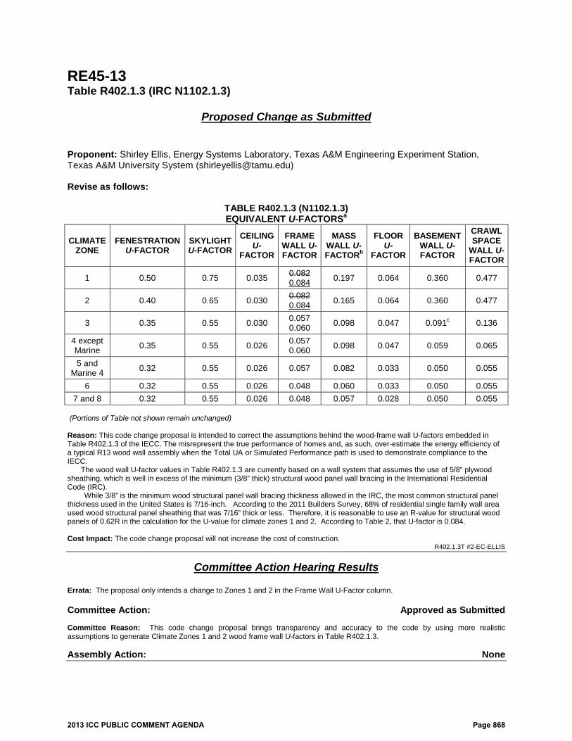
RE45-13 Table R402.1.3 (IRC N1102.1.3)
Proposed Change as Submitted
Proponent: Shirley Ellis, Energy Systems Laboratory, Texas A&M Engineering Experiment Station, Texas A&M University System ([email protected]) Revise as follows:
TABLE R402.1.3 (N1102.1.3) EQUIVALENT U-FACTORSa
CLIMATE ZONE
FENESTRATION U-FACTOR
SKYLIGHT U-FACTOR
CEILING U-
FACTOR
FRAME WALL U-FACTOR
MASS WALL U-FACTORb
FLOOR U-
FACTOR
BASEMENT WALL U-FACTOR
CRAWL SPACE
WALL U-FACTOR
1 0.50 0.75 0.035 0.082 0.084 0.197 0.064 0.360 0.477
2 0.40 0.65 0.030 0.082 0.084 0.165 0.064 0.360 0.477
3 0.35 0.55 0.030 0.057 0.060 0.098 0.047 0.091c 0.136
4 except Marine 0.35 0.55 0.026 0.057
0.060 0.098 0.047 0.059 0.065
5 and Marine 4 0.32 0.55 0.026 0.057 0.082 0.033 0.050 0.055
6 0.32 0.55 0.026 0.048 0.060 0.033 0.050 0.055 7 and 8 0.32 0.55 0.026 0.048 0.057 0.028 0.050 0.055
(Portions of Table not shown remain unchanged) Reason: This code change proposal is intended to correct the assumptions behind the wood-frame wall U-factors embedded in Table R402.1.3 of the IECC. The misrepresent the true performance of homes and, as such, over-estimate the energy efficiency of a typical R13 wood wall assembly when the Total UA or Simulated Performance path is used to demonstrate compliance to the IECC. The wood wall U-factor values in Table R402.1.3 are currently based on a wall system that assumes the use of 5/8” plywood sheathing, which is well in excess of the minimum (3/8” thick) structural wood panel wall bracing in the International Residential Code (IRC). While 3/8” is the minimum wood structural panel wall bracing thickness allowed in the IRC, the most common structural panel thickness used in the United States is 7/16-inch. According to the 2011 Builders Survey, 68% of residential single family wall area used wood structural panel sheathing that was 7/16” thick or less. Therefore, it is reasonable to use an R-value for structural wood panels of 0.62R in the calculation for the U-value for climate zones 1 and 2. According to Table 2, that U-factor is 0.084. Cost Impact: The code change proposal will not increase the cost of construction.
R402.1.3T #2-EC-ELLIS
Committee Action Hearing Results Errata: The proposal only intends a change to Zones 1 and 2 in the Frame Wall U-Factor column. Committee Action: Approved as Submitted Committee Reason: This code change proposal brings transparency and accuracy to the code by using more realistic assumptions to generate Climate Zones 1 and 2 wood frame wall U-factors in Table R402.1.3. Assembly Action: None
2013 ICC PUBLIC COMMENT AGENDA Page 868

Individual Consideration Agenda
This item is on the agenda for individual consideration because public comments were submitted. Public Comment 1: Tom Kositzky, representing the Coalition for Fair Energy Codes, requests As Modified by this Public Comment. Modify the proposal as follows:
TABLE R402.1.3 EQUIVALENT U-FACTORSa
CLIMATE ZONE
FENESTRATION U-FACTOR
SKYLIGHT U-FACTOR
CEILING U-FACTOR
FRAME WALL U-FACTOR
MASS WALL U-FACTORb
FLOOR U-FACTOR
BASEMENT WALL U-FACTOR
CRAWL SPACE
WALL U-FACTOR
1 0.50 0.75 0.035 0.084 0.085 0.197 0.064 0.360 0.477
2 0.40 0.65 0.030 0.084 0.085 0.165 0.064 0.360 0.477
3 0.35 0.55 0.030 0.057 0.098 0.047 0.091c 0.136 4 except Marine 0.35 0.55 0.026 0.057 0.098 0.047 0.059 0.065
5 and Marine 4 0.32 0.55 0.026 0.057 0.082 0.033 0.050 0.055
6 0.32 0.55 0.026 0.048 0.060 0.033 0.050 0.055 7 and 8 0.32 0.55 0.026 0.048 0.057 0.028 0.050 0.055
(Portions of Table not shown remains unchanged) Commenter’s Reason: The committee chose to approve RE45-13 which set the U-factors for Climate Zones 1 and 2 at U-0.084 which we agree is more correct than the U-0.082 factor in the 2012 IECC. While the assembly assumption in RE45 are very close, accepting the 0.084 U-factor sets a precedent that the U-factors can be established without using the code minimum wood structural panel wall bracing in the frame wall system assumptions. The 0.084 U-factor assumes that the wood sheathing is 7/16 inches. The code minimum wood structural panel sheathing thickness for wall bracing is 3/8 inches. Therefore, the base calculations should use the R-value for 3/8” thick wood structural panels in the evaluation. When the calculation is done with the correct sheathing R-value, the calculated U-factor is U-0.085. This is the U-factor that should be used. We urge the support of this code change proposal as modified by this public comment.
U-Factor Calculations – Climate Zoness 1-2 Wood Framed Walls
2013 ICC PUBLIC COMMENT AGENDA Page 869

Public Comment 2: Brian Dean, ICF International, representing the Energy Efficient Codes Coalition; Jeff Harris, Alliance to Save Energy; Harry Misuriello, American Council for an Energy-Efficient Economy (ACEEE); Bill Prindle, representing the Energy Efficient Codes Coalition; Garrett Stone, Brickfield, Burchette, Ritts & Stone, PC; Donald J. Vigneau, Northeast Energy Efficiency Partnerships Inc., request Disapproval. Commenter’s Reason: We recommend disapproval of RE45 for the same reason as RE44. Proposals RE44-47 and RE50 should all be disapproved because they collectively weaken the energy efficiency requirements of the IECC’s U-factor, Total UA, and Simulated Performance alternatives. These proposals all suffer from the same fatal flaw – they treat the U-factor table (R402.1.3) as a direct product of the prescriptive table (R402.1.1), and attempt to align the two tables based on a single method of construction. The result is an unnecessary weakening of the stringency of the IECC and constitutes backsliding from the 2012 IECC. RE45-13 Final Action: AS AM AMPC D
Wall Thermal Resistance by Component
5/8" Wood Sheathing 7/16" Wood Sheathing 3/8" Wood Sheathing
R-Value Studs
R-Value Cavity
Assembly Value
R-Value Studs
R-Value Cavity
Assembly Value
R-Value Studs
R-Value Cavity
Assembly Value
Wall - Outside Winter Air Film 0.25 0.25 0.25
Siding - Plywood 0.59 0.59 0.59
Continuous Insulation 0 0 0 Wood Structural Panel Sheathing 0.83 (5/8") 0.62 (7/16") 0.47 (3/8")
Stud/Cavity Insulation 4.375 13 4.375 13 4.375 13
1/2" Drywall 0.45 0.45 0.45
Inside Air Film 0.68 0.68 0.68
Studs at 16" o.c. 25% 75% 25% 75% 25% 75%
Total Wall R-Values 7.18 15.80 12.15 6.97 15.59 11.90 6.82 15.44 11.73
Total Wall U-Factors 0.139 0.063 0.0823 0.144 0.064 0.0840 0.147 0.065 0.0853
2013 ICC PUBLIC COMMENT AGENDA Page 870

RE46-13 Table R402.1.3 (IRC Table N1102.1.3)
Proposed Change as Submitted Proponent: Tom Kositzky, representing Coalition for Fair Energy Codes Revise as follows:
TABLE R402.1.3 (N1102.1.3) EQUIVALENT U-FACTORSa
CLIMATE ZONE
FENESTRATION U-FACTOR
SKYLIGHT U-FACTOR
CEILING U-
FACTOR
FRAME WALL U-FACTOR
MASS WALL U-FACTORb
FLOOR U-
FACTOR
BASEMENT WALL U-FACTOR
CRAWL SPACE
WALL U-FACTOR
1 0.50 0.75 0.035 0.082 0.197 0.064 0.360 0.477 2 0.40 0.65 0.030 0.082 0.165 0.064 0.360 0.477
3 0.35 0.55 0.030 0.057 0.060 0.098 0.047 0.091c 0.136
4 except Marine 0.35 0.55 0.026 0.057
0.060 0.098 0.047 0.059 0.065
5 and Marine 4 0.32 0.55 0.026 0.057
0.060 0.082 0.033 0.050 0.055
6 0.32 0.55 0.026 0.048 0.060 0.033 0.050 0.055 7 and 8 0.32 0.55 0.026 0.048 0.057 0.028 0.050 0.055
(Portions of Table not shown remain unchanged) Reason: This code change proposal is intended to bring transparency and accuracy to the code by using more realistic assumptions to generate Climate Zones 3-5 wood frame wall U-factors in Table R402.1.3. The REScheckTM assumptions result in U-factors that misrepresent the true energy performance of wood walls and, as such, over-estimate the energy efficiency of a typical R20 and R13+5 wood wall assemblies when the assembly U-factor, Total UA alternative or Simulated Performance alternative is used to demonstrate compliance. This proposal corrects two REScheckTM assumptions which were used to generate the wood wall U-factors in Table R402.1.3. 1. It was assumed that 5/8-inch plywood wall sheathing is used.
(This assumption is in excess of the minimum required, 3/8-inch thick, wood structural panel wall bracing that is required in the IRC.)
2. The assumption that a double layer of wall sheathing is used for R13+5 assemblies. (A layer of R5 continuous insulation with an additional layer of continuous 5/8-inch plywood wall sheathing is assumed.)
Both of these assumptions are not based upon common practice nor are they required by the IRC. In order to establish baseline requirements that are fair to all products and systems, the code should be based upon the minimum performing assemblies that meet the provisions of the code. The minimum performing system in IECC Table R402.1.1 is found in footnote h. It allows continuous insulating sheathing to be used in combination with intermittent structural wall bracing (a.k.a., corner bracing) and results in a U-factor of 0.064 as shown below in Table 3. Recognizing the strong opposition regarding the use of this common prescriptive wall assembly (footnote h) as a basis for generating U-factors, we propose basing the Climate Zone 3-5 continuous insulating sheathing U-factor on an assembly that uses let-in-bracing (per IRC Table R602.10.4) or metal strap bracing to provide lateral support. The resulting U-factor of 0.060 correlates to the U-factor for an R20 wall when code minimum 3/8-inch wood structural panel sheathing is used in lieu of 5/8-inch plywood. (See Table 2 below.) A U-factor of 0.060 aligns more closely with common construction practices and would be a more reasonable value for wood frame walls in Climate Zones 3-5.
We ask the support of the committee for this proposal. Table 1 shows the REScheckTM component assumptions which were used to determine the prescriptive U-factors in Table R402.1.3 of the IECC1, 2. The cells representing the 5/8-inch plywood and double layer wall sheathing assumptions are shaded. Table 2 shows the component assumptions for the U-factor being proposed. Table 3 represents a code-compliant and common construction approach which is provided for reference.
2013 ICC PUBLIC COMMENT AGENDA Page 871
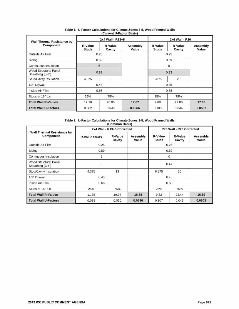
Table 1. U-Factor Calculations for Climate Zones 3-5, Wood Framed Walls (Current U-Factor Basis)
Wall Thermal Resistance by Component
2x4 Wall - R13+5 2x6 Wall - R20
R-Value Studs
R-Value Cavity
Assembly Value
R-Value Studs
R-Value Cavity
Assembly Value
Outside Air Film 0.25 0.25
Siding 0.59 0.59
Continuous Insulation 5 0 Wood Structural Panel Sheathing (5/8”) 0.83 0.83
Stud/Cavity Insulation 4.375 13 6.875 20
1/2" Drywall 0.45 0.45
Inside Air Film 0.68 0.68
Studs at 16" o.c. 25% 75% 25% 75%
Total Wall R-Values 12.18 20.80 17.67 9.68 22.80 17.03
Total Wall U-Factors 0.082 0.048 0.0566 0.103 0.044 0.0587
Table 2. U-Factor Calculations for Climate Zones 3-5, Wood Framed Walls (Common Basis)
Wall Thermal Resistance by Component
2x4 Wall - R13+5 Corrected 2x6 Wall - R20 Corrected
R-Value Studs R-Value Cavity
Assembly Value
R-Value Studs
R-Value Cavity
Assembly Value
Outside Air Film 0.25 0.25
Siding 0.59 0.59
Continuous Insulation 5 0
Wood Structural Panel Sheathing (3/8”) 0 0.47 Stud/Cavity Insulation 4.375 13 6.875 20
1/2" Drywall 0.45 0.45
Inside Air Film 0.68 0.68
Studs at 16" o.c. 25% 75% 25% 75%
Total Wall R-Values 11.35 19.97 16.78 9.32 22.44 16.59
Total Wall U-Factors 0.088 0.050 0.0596 0.107 0.045 0.0603
2013 ICC PUBLIC COMMENT AGENDA Page 872
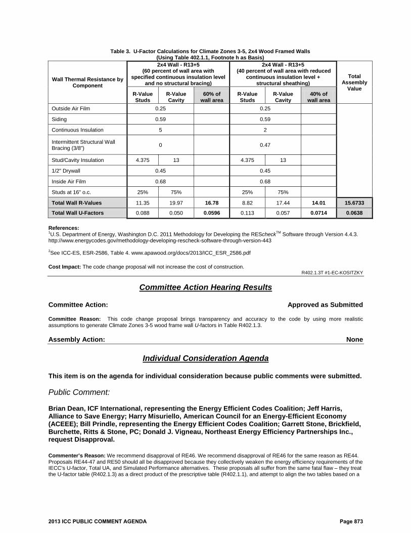
Table 3. U-Factor Calculations for Climate Zones 3-5, 2x4 Wood Framed Walls (Using Table 402.1.1, Footnote h as Basis)
Wall Thermal Resistance by Component
2x4 Wall - R13+5 (60 percent of wall area with
specified continuous insulation level and no structural bracing)
2x4 Wall - R13+5 (40 percent of wall area with reduced
continuous insulation level + structural sheathing)
Total Assembly
Value R-Value Studs
R-Value Cavity
60% of wall area
R-Value Studs
R-Value Cavity
40% of wall area
Outside Air Film 0.25 0.25
Siding 0.59 0.59
Continuous Insulation 5 2
Intermittent Structural Wall Bracing (3/8”) 0 0.47 Stud/Cavity Insulation 4.375 13 4.375 13
1/2" Drywall 0.45 0.45
Inside Air Film 0.68 0.68
Studs at 16" o.c. 25% 75% 25% 75%
Total Wall R-Values 11.35 19.97 16.78 8.82 17.44 14.01 15.6733
Total Wall U-Factors 0.088 0.050 0.0596 0.113 0.057 0.0714 0.0638 References: 1U.S. Department of Energy, Washington D.C. 2011 Methodology for Developing the REScheckTM Software through Version 4.4.3. http://www.energycodes.gov/methodology-developing-rescheck-software-through-version-443 2See ICC-ES, ESR-2586, Table 4. www.apawood.org/docs/2013/ICC_ESR_2586.pdf Cost Impact: The code change proposal will not increase the cost of construction.
R402.1.3T #1-EC-KOSITZKY
Committee Action Hearing Results Committee Action: Approved as Submitted Committee Reason: This code change proposal brings transparency and accuracy to the code by using more realistic assumptions to generate Climate Zones 3-5 wood frame wall U-factors in Table R402.1.3. Assembly Action: None
Individual Consideration Agenda
This item is on the agenda for individual consideration because public comments were submitted. Public Comment: Brian Dean, ICF International, representing the Energy Efficient Codes Coalition; Jeff Harris, Alliance to Save Energy; Harry Misuriello, American Council for an Energy-Efficient Economy (ACEEE); Bill Prindle, representing the Energy Efficient Codes Coalition; Garrett Stone, Brickfield, Burchette, Ritts & Stone, PC; Donald J. Vigneau, Northeast Energy Efficiency Partnerships Inc., request Disapproval. Commenter’s Reason: We recommend disapproval of RE46. We recommend disapproval of RE46 for the same reason as RE44. Proposals RE44-47 and RE50 should all be disapproved because they collectively weaken the energy efficiency requirements of the IECC’s U-factor, Total UA, and Simulated Performance alternatives. These proposals all suffer from the same fatal flaw – they treat the U-factor table (R402.1.3) as a direct product of the prescriptive table (R402.1.1), and attempt to align the two tables based on a
2013 ICC PUBLIC COMMENT AGENDA Page 873

single method of construction. The result is an unnecessary weakening of the stringency of the IECC and constitutes backsliding from the 2012 IECC. RE46-13 Final Action: AS AM AMPC D
2013 ICC PUBLIC COMMENT AGENDA Page 874
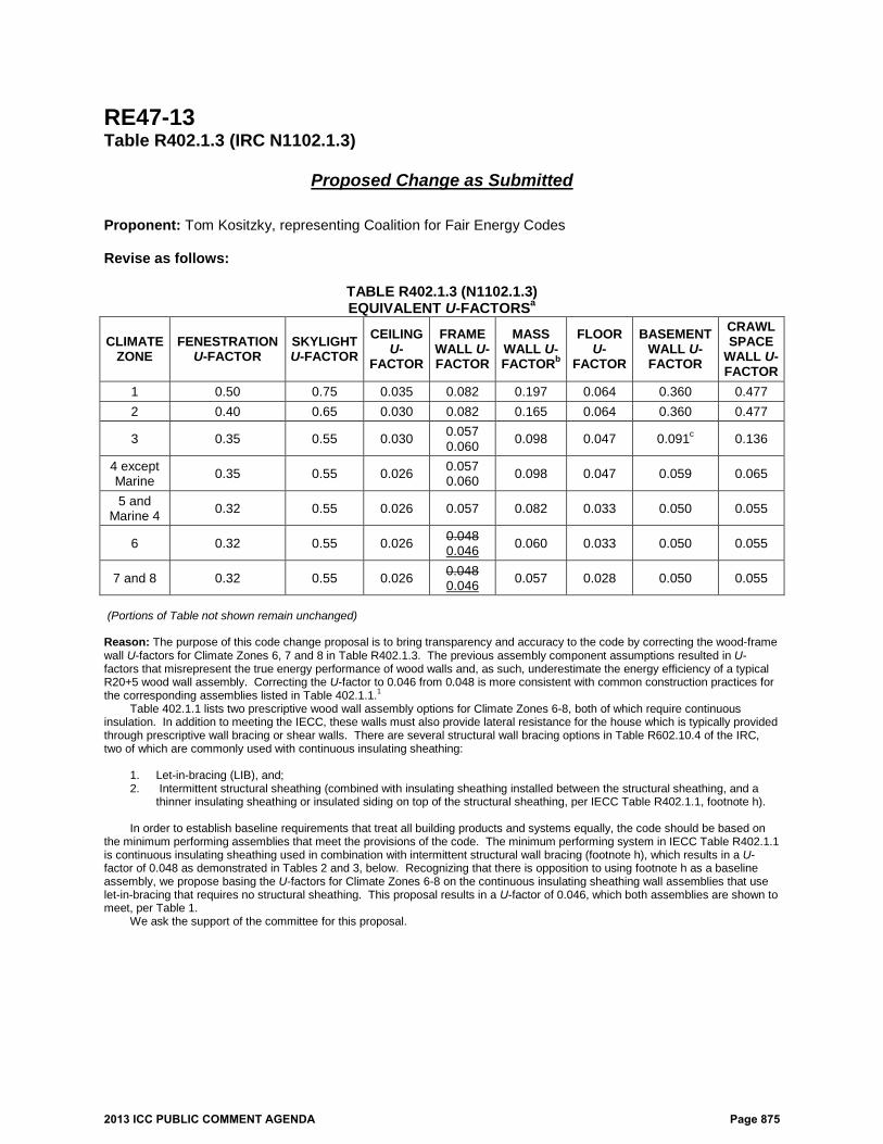
RE47-13 Table R402.1.3 (IRC N1102.1.3)
Proposed Change as Submitted Proponent: Tom Kositzky, representing Coalition for Fair Energy Codes Revise as follows:
TABLE R402.1.3 (N1102.1.3) EQUIVALENT U-FACTORSa
CLIMATE ZONE
FENESTRATION U-FACTOR
SKYLIGHT U-FACTOR
CEILING U-
FACTOR
FRAME WALL U-FACTOR
MASS WALL U-FACTORb
FLOOR U-
FACTOR
BASEMENT WALL U-FACTOR
CRAWL SPACE
WALL U-FACTOR
1 0.50 0.75 0.035 0.082 0.197 0.064 0.360 0.477 2 0.40 0.65 0.030 0.082 0.165 0.064 0.360 0.477
3 0.35 0.55 0.030 0.057 0.060 0.098 0.047 0.091c 0.136
4 except Marine 0.35 0.55 0.026 0.057
0.060 0.098 0.047 0.059 0.065
5 and Marine 4 0.32 0.55 0.026 0.057 0.082 0.033 0.050 0.055
6 0.32 0.55 0.026 0.048 0.046 0.060 0.033 0.050 0.055
7 and 8 0.32 0.55 0.026 0.048 0.046 0.057 0.028 0.050 0.055
(Portions of Table not shown remain unchanged) Reason: The purpose of this code change proposal is to bring transparency and accuracy to the code by correcting the wood-frame wall U-factors for Climate Zones 6, 7 and 8 in Table R402.1.3. The previous assembly component assumptions resulted in U-factors that misrepresent the true energy performance of wood walls and, as such, underestimate the energy efficiency of a typical R20+5 wood wall assembly. Correcting the U-factor to 0.046 from 0.048 is more consistent with common construction practices for the corresponding assemblies listed in Table 402.1.1.1
Table 402.1.1 lists two prescriptive wood wall assembly options for Climate Zones 6-8, both of which require continuous insulation. In addition to meeting the IECC, these walls must also provide lateral resistance for the house which is typically provided through prescriptive wall bracing or shear walls. There are several structural wall bracing options in Table R602.10.4 of the IRC, two of which are commonly used with continuous insulating sheathing:
1. Let-in-bracing (LIB), and; 2. Intermittent structural sheathing (combined with insulating sheathing installed between the structural sheathing, and a
thinner insulating sheathing or insulated siding on top of the structural sheathing, per IECC Table R402.1.1, footnote h).
In order to establish baseline requirements that treat all building products and systems equally, the code should be based on the minimum performing assemblies that meet the provisions of the code. The minimum performing system in IECC Table R402.1.1 is continuous insulating sheathing used in combination with intermittent structural wall bracing (footnote h), which results in a U-factor of 0.048 as demonstrated in Tables 2 and 3, below. Recognizing that there is opposition to using footnote h as a baseline assembly, we propose basing the U-factors for Climate Zones 6-8 on the continuous insulating sheathing wall assemblies that use let-in-bracing that requires no structural sheathing. This proposal results in a U-factor of 0.046, which both assemblies are shown to meet, per Table 1.
We ask the support of the committee for this proposal.
2013 ICC PUBLIC COMMENT AGENDA Page 875

Table 1. U-Factor Calculations for Climate Zones 6-8 Wood Framed Walls
Wall Thermal Resistance by Component
2x4 Wall - R13+10 2x6 Wall - R20+5
R-Value Studs
R-Value Cavity
Assembly Value
R-Value Studs
R-Value Cavity
Assembly Value
Outside Air Film 0.25 0.25
Siding 0.59 0.59
Continuous Insulation 10 5 Wood Structural Panel Sheathing 0 0
Stud/Cavity Insulation 4.375 13 6.875 20
1/2" Drywall 0.45 0.45
Inside Air Film 0.68 0.68
Studs at 16" o.c. 25% 75% 25% 75%
Total Wall R-Values 16.35 24.97 22.06 13.85 26.97 21.80
Total Wall U-Factors 0.061 0.040 0.0453 0.072 0.037 0.0459
Table 2. U-Factor Calculations for Climate Zone 6-8, 2x6 Wood Framed Wall (Using Table 402.1.1, Footnote h as Basis)
Wall Thermal Resistance by Component
2x6 Wall - R20+5 (60 percent of wall area with
specified continuous insulation level and no structural bracing)
2x6 Wall - R20+5 (40 percent of wall area with reduced
continuous insulation level + structural sheathing)
Total Assembly
Value R-Value Studs
R-Value Cavity
60% of wall area
R-Value Studs
R-Value Cavity
40% of wall area
Outside Air Film 0.25 0.25
Siding 0.59 0.59
Continuous Insulation 5 2
Intermittent Structural Wall Bracing (3/8”) 0 0.47 Stud/Cavity Insulation 6.875 20 6.875 20
1/2" Drywall 0.45 0.45
Inside Air Film 0.68 0.68
Studs at 16" o.c. 25% 75% 25% 75%
Total Wall R-Values 13.85 26.97 21.80 11.32 24.44 18.95 20.66
Total Wall U-Factors 0.072 0.037 0.0459 0.087 0.041 0.0528 0.0484
2013 ICC PUBLIC COMMENT AGENDA Page 876

Table 3. U-Factor Calculations for Climate Zone 6-8, 2x4 Wood Framed Walls (Using Table 402.1.1, Footnote h as Basis)
Wall Thermal Resistance by Component
2x4 Wall - R13+10 (60 percent of wall area with
specified continuous insulation level and no structural bracing)
2x4 Wall - R13+10 (40 percent of wall area with reduced
continuous insulation level + structural sheathing)
Total Assembly
Value R-Value Studs
R-Value Cavity
60% of wall area
R-Value Studs
R-Value Cavity
40% of wall area
Outside Air Film 0.25 0.25
Siding 0.59 0.59
Continuous Insulation 10 7
Intermittent Structural Wall Bracing (3/8”) 0 0.47 Stud/Cavity Insulation 4.375 13 4.375 13
1/2" Drywall 0.45 0.45
Inside Air Film 0.68 0.68
Studs at 16" o.c. 25% 75% 25% 75%
Total Wall R-Values 16.35 24.97 22.06 13.82 22.44 19.41 21.0001
Total Wall U-Factors 0.061 0.040 0.0453 0.072 0.045 0.0515 0.0476 References:1 See ICC-ES, ESR-2586, Table 4. www.apawood.org/docs/2013/ICC_ESR_2586.pdf Cost Impact: The code change proposal will not increase the cost of construction.
R402.1.3T #2-EC-KOSITZKY
Committee Action Hearing Results Errata: The proposal only intends a change to Zones 6, 7 and 8 in the Frame Wall U-Factor column. Committee Action: Approved as Submitted Committee Reason: This code change proposal brings transparency and accuracy to the code by using more realistic assumptions to generate Climate Zones 6, 7 and 8 wood frame wall U-factors in Table R402.1.3. Assembly Action: None
Individual Consideration Agenda
This item is on the agenda for individual consideration because public comments were submitted. Public Comment: Brian Dean, ICF International, representing the Energy Efficient Codes Coalition; Jeff Harris, Alliance to Save Energy; Harry Misuriello, American Council for an Energy-Efficient Economy (ACEEE); Bill Prindle, representing the Energy Efficient Codes Coalition; Garrett Stone, Brickfield, Burchette, Ritts & Stone, PC; Donald J. Vigneau, Northeast Energy Efficiency Partnerships Inc., request Disapproval. Commenter’s Reason: We recommend disapproval of RE47. We recommend disapproval of RE47 for the same reason as RE44. Proposals RE44-47 and RE50 should all be disapproved because they collectively weaken the energy efficiency requirements of the IECC’s U-factor, Total UA, and Simulated Performance alternatives. These proposals all suffer from the same fatal flaw – they treat the U-factor table (R402.1.3) as a direct product of the prescriptive table (R402.1.1), and attempt to align the two tables based on a
2013 ICC PUBLIC COMMENT AGENDA Page 877

single method of construction. The result is an unnecessary weakening of the stringency of the IECC and constitutes backsliding from the 2012 IECC. RE47-13 Final Action: AS AM AMPC D
2013 ICC PUBLIC COMMENT AGENDA Page 878

RE48-13 Table R402.1.3 (IRC N1102.1.3)
Proposed Change as Submitted Proponent: Tom Kositzky, representing Coalition for Fair Energy Codes Revise as follows:
TABLE R402.1.3 (N1102.1.3) EQUIVALENT U-FACTORSa
CLIMATE ZONE
FENESTRATION U-FACTOR
SKYLIGHT U-FACTOR
CEILING U-
FACTOR
FRAME WALL U-FACTOR
MASS WALL U-FACTORb
FLOOR U-
FACTOR
BASEMENT WALL U-FACTOR
CRAWL SPACE
WALL U-FACTOR
1 0.50 0.75 0.035 0.082 0.085 0.197 0.064 0.360 0.477
2 0.40 0.65 0.030 0.082 0.085 0.165 0.064 0.360 0.477
3 0.35 0.55 0.030 0.057 0.098 0.047 0.091c 0.136 4 except Marine 0.35 0.55 0.026 0.057 0.098 0.047 0.059 0.065
5 and Marine 4 0.32 0.55 0.026 0.057
0.082 0.033 0.050 0.055
6 0.32 0.55 0.026 0.048 0.060 0.033 0.050 0.055 7 and 8 0.32 0.55 0.026 0.048 0.057 0.028 0.050 0.055
(Portions of Table not shown remain unchanged) Reason: This code change proposal is intended to bring transparency and accuracy to the code by using more realistic assumptions to generate the Climate Zone 1 and 2 wood-frame wall U-factors in Table R402.1.3. The previous assumptions resulted in U-factors that misrepresent the true energy performance of wood walls and, as such, overestimate the energy efficiency of a typical R13 wood wall assembly when the assembly U-factor alternative, the total UA alternative or Simulated Performance alternative is used to demonstrate compliance. The wood wall U-factors in Table R402.1.3 are currently based on an assembly that assumes the use of 5/8-inch plywood sheathing, which is well in excess of the minimum 3/8-inch thick structural wood panel wall bracing in the IRC. Table 1 incorporates the REScheckTM assumptions which were used to determine the prescriptive U-factors in Table R402.1.3 of the IECC1,2 in the left hand columns of the table. This base calculation assumes that 5/8-inch thick plywood is used as the sheathing material, resulting in the current 0.082 U-factor. The proposed component R-value basis in the right-hand columns in Table 1 uses the same REScheckTM assumptions but incorporates the R-value for 3/8-inch wood structural panel sheathing, resulting in a U-factor of 0.085.
Adjusting the Climate Zone 1-2 U-factors in Table R402.1.3 to 0.085 will more accurately reflect the energy efficiency of an R13 wood wall assembly when the Total UA or Simulated Performance alternatives are used to demonstrate compliance.
We ask the support of the committee for this proposal.
2013 ICC PUBLIC COMMENT AGENDA Page 879

Table 1. U-Factor Calculations for Climate Zones 1-2 Wood Framed Walls
Wall Thermal Resistance by Component
Current Component R-Value Basis Proposed Component R-Value Basis
R-Value Studs
R-Value Cavity
Assembly Value
R-Value Studs
R-Value Cavity
Assembly Value
Outside Air Film 0.25 0.25
Siding 0.59 0.59
Continuous Insulation 0 0 Wood Structural Panel Sheathing 0.83 (5/8”) 0.47 (3/8”)
Stud/Cavity Insulation 4.38 13 4.38 13
1/2" Drywall 0.45 0.45
Inside Air Film 0.68 0.68
Studs at 16" o.c. 25% 75% 25% 75%
Total Wall R-Values 7.18 15.80 12.15 6.82 15.44 11.73
Total Wall U-Factors 0.139 0.063 0.0823 0.147 0.065 0.0853 References: 1U.S. Department of Energy, Washington D.C. 2011 Methodology for Developing the REScheckTM Software through Version 4.4.3. http://www.energycodes.gov/methodology-developing-rescheck-software-through-version-443 2See ICC-ES, ESR-2586, Table 4. www.apawood.org/docs/2013/ICC_ESR_2586.pdf Cost Impact: The code change proposal will not increase the cost of construction.
R402.1.3T #3-EC-KOSITZKY
Committee Action Hearing Results Committee Action: Disapproved Committee Reason: The proposed changes would be inconsistent with the changes approved in RE45-13. Assembly Action: None
Individual Consideration Agenda
This item is on the agenda for individual consideration because a public comment was submitted. Public Comment: Tom Kositzky, representing Coalition for Fair Energy Codes, requests Approval as Submitted. Commenter’s Reason: The committee chose to approve RE45-13 which set the U-factors for Climate Zones 1 and 2 at U-0.084, which we agree is more correct than the 0.082 U-factor in the 2012 IECC. While the assembly assumptions in RE45 are very close, accepting the 0.084 U-factor sets a precedent that the U-factors can be established without using the code minimum wood structural panel wall bracing in the frame wall system assumptions. The 0.084 U-factor assumes that the wood sheathing is 7/16 inches. The code minimum wood structural panel sheathing thickness for wall bracing is 3/8 inches. Therefore, the base calculations should use the R-value for 3/8” thick wood structural panels in the evaluation. When the calculation is done with the correct sheathing R-value, the calculated U-factor is U-0.085. This is the U-factor that should be used. We urge the support of RE48 as submitted.
2013 ICC PUBLIC COMMENT AGENDA Page 880

Table 1. U-Factor Calculations for Climate Zones 1-2 Wood Framed Walls
Wall Thermal Resistance by Component
Current Component R-Value Basis Proposed Component R-Value Basis
R-Value Studs
R-Value Cavity
Assembly Value
R-Value Studs
R-Value Cavity
Assembly Value
Outside Air Film 0.25 0.25
Siding 0.59 0.59
Continuous Insulation 0 0 Wood Structural Panel Sheathing 0.83 (5/8”) 0.47 (3/8”)
Stud/Cavity Insulation 4.38 13 4.38 13
1/2" Drywall 0.45 0.45
Inside Air Film 0.68 0.68
Studs at 16" o.c. 25% 75% 25% 75%
Total Wall R-Values 7.18 15.80 12.15 6.82 15.44 11.73
Total Wall U-Factors 0.139 0.063 0.0823 0.147 0.065 0.0853
RE48-13 Final Action: AS AM AMPC D
2013 ICC PUBLIC COMMENT AGENDA Page 881
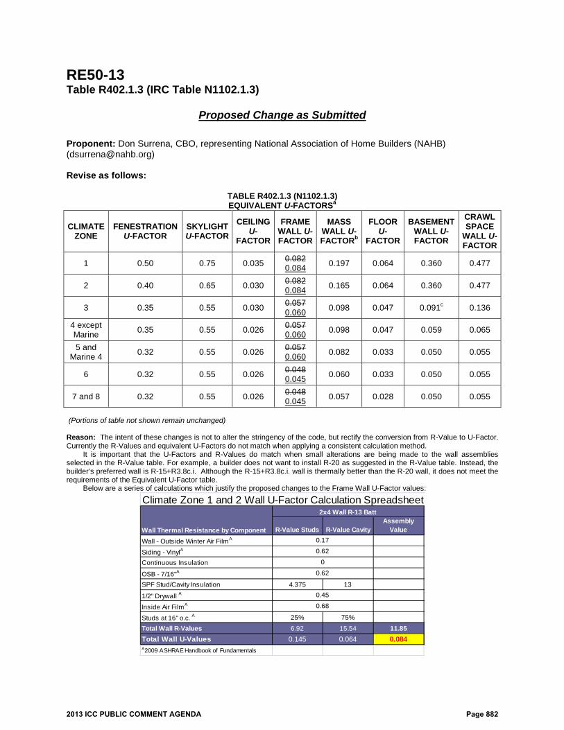
RE50-13 Table R402.1.3 (IRC Table N1102.1.3)
Proposed Change as Submitted Proponent: Don Surrena, CBO, representing National Association of Home Builders (NAHB) ([email protected]) Revise as follows:
TABLE R402.1.3 (N1102.1.3) EQUIVALENT U-FACTORSa
CLIMATE ZONE
FENESTRATION U-FACTOR
SKYLIGHT U-FACTOR
CEILING U-
FACTOR
FRAME WALL U-FACTOR
MASS WALL U-FACTORb
FLOOR U-
FACTOR
BASEMENT WALL U-FACTOR
CRAWL SPACE
WALL U-FACTOR
1 0.50 0.75 0.035 0.082 0.084 0.197 0.064 0.360 0.477
2 0.40 0.65 0.030 0.082 0.084 0.165 0.064 0.360 0.477
3 0.35 0.55 0.030 0.057 0.060 0.098 0.047 0.091c 0.136
4 except Marine 0.35 0.55 0.026 0.057
0.060 0.098 0.047 0.059 0.065
5 and Marine 4 0.32 0.55 0.026 0.057
0.060 0.082 0.033 0.050 0.055
6 0.32 0.55 0.026 0.048 0.045 0.060 0.033 0.050 0.055
7 and 8 0.32 0.55 0.026 0.048 0.045 0.057 0.028 0.050 0.055
(Portions of table not shown remain unchanged) Reason: The intent of these changes is not to alter the stringency of the code, but rectify the conversion from R-Value to U-Factor. Currently the R-Values and equivalent U-Factors do not match when applying a consistent calculation method.
It is important that the U-Factors and R-Values do match when small alterations are being made to the wall assemblies selected in the R-Value table. For example, a builder does not want to install R-20 as suggested in the R-Value table. Instead, the builder’s preferred wall is R-15+R3.8c.i. Although the R-15+R3.8c.i. wall is thermally better than the R-20 wall, it does not meet the requirements of the Equivalent U-Factor table.
Below are a series of calculations which justify the proposed changes to the Frame Wall U-Factor values:
R-Value Studs R-Value CavityAssembly
Value
Wall - Outside Winter Air FilmA
Siding - VinylA
Continuous Insulation
OSB - 7/16"A
SPF Stud/Cavity Insulation 4.375 13
1/2" Drywall A
Inside Air FilmA
Studs at 16" o.c. A 25% 75%
Total Wall R-Values 6.92 15.54 11.85Total Wall U-Values 0.145 0.064 0.084A2009 ASHRAE Handbook of Fundamentals
Climate Zone 1 and 2 Wall U-Factor Calculation Spreadsheet
Wall Thermal Resistance by Component
2x4 Wall R-13 Batt
0.17
0.62
0
0.62
0.45
0.68
2013 ICC PUBLIC COMMENT AGENDA Page 882

R-Value Studs R-Value CavityAssembly U-Factor R-Value Studs R-Value Cavity
Assembly U-Factor
Wall - Outside Winter Air FilmA
Siding - VinylA
Continuous Insulation
OSB - 7/16"A
SPF Stud/Cavity Insulation 4.375 13 6.875 20
1/2" Drywall A
Inside Air FilmA
Studs at 16" o.c. A 25% 75% 25% 75%
Total Wall R-Values 11.92 20.54 17.39 9.42 22.54 16.71
Total Wall U-Factor 0.084 0.049 0.057 0.106 0.044 0.060A2009 ASHRAE Handbook of Fundamentals
Climate Zones 3-5 Wall U-Factor Calculation Spreadsheet
Wall Thermal Resistance by Component
2x4 Wall R-13+R5 2x6 Wall R-20
0.62 0.62
0.17 0.17
0.62
5 0
0.45
0.68 0.68
0.45
0.62
R-Value Studs R-Value CavityAssembly
Value R-Value Studs R-Value CavityAssembly
Value
Wall - Outside Winter Air FilmA
Siding - VinylA
Continuous Insulation
OSB - 7/16"A
SPF Stud/Cavity Insulation 4.375 13 6.875 20
1/2" Drywall A
Inside Air FilmA
Studs at 16" o.c. A 25% 75% 25% 75%
Total Wall R-Values 16.92 25.54 22.65 14.42 27.54 22.43Total Wall U-Values 0.059 0.039 0.044 0.069 0.036 0.045A2009 ASHRAE Handbook of Fundamentals
Climate Zones 6-8 Wall U-Factor Calculation Spreadsheet
Wall Thermal Resistance by Component
2x4 Wall R-13+R-10 c.i. 2x6 Wall R-20+R-5 c.i.
0.17 0.17
0.62 0.62
10 5
0.62 0.62
0.45 0.45
0.68 0.68
Referenced Standards: None Cost Impact: The code change proposal will not increase the cost of construction.
R402.1.3T-EC-SURRENA
Committee Action Hearing Results Committee Action: Approved as Submitted Committee Reason: This proposal provides a consistent, comprehensive code change for frame wall U-Factors for all climate zones. The values are consistent with previous actions (RE44-RE47). Assembly Action: None
2013 ICC PUBLIC COMMENT AGENDA Page 883
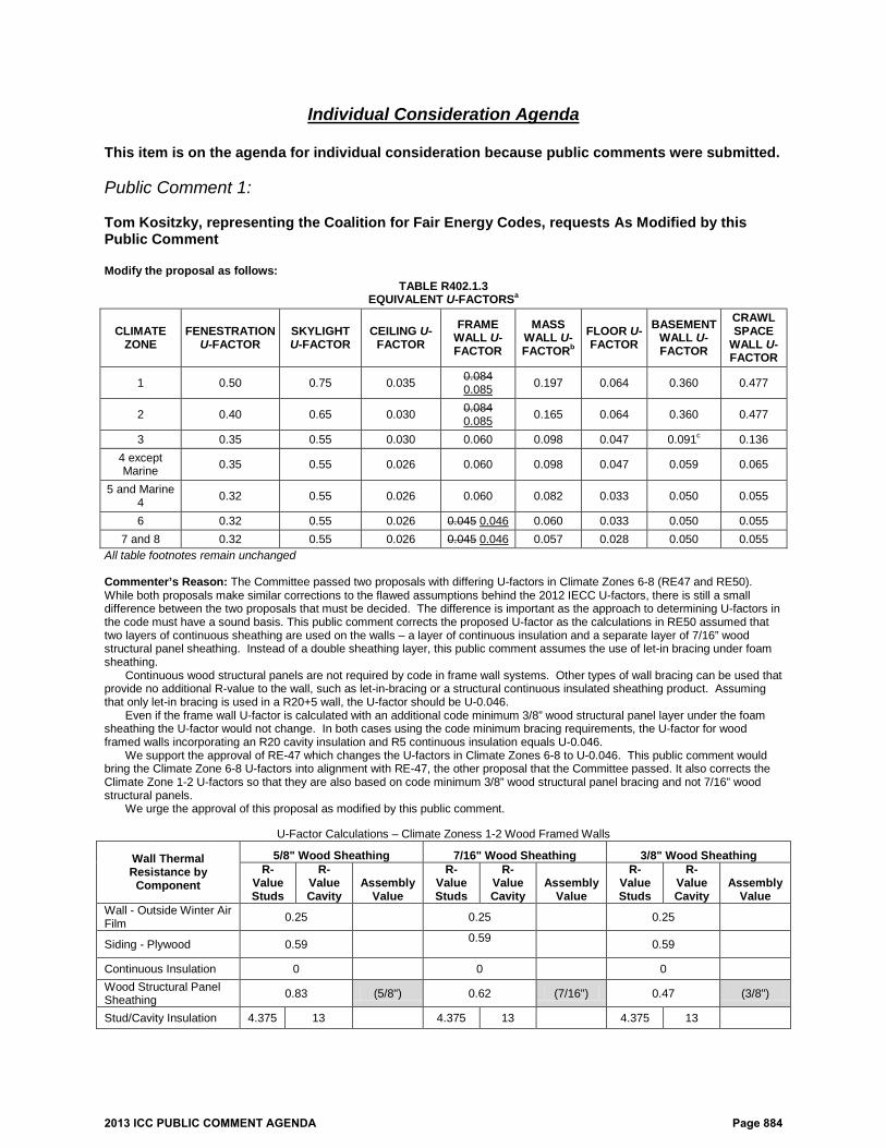
Individual Consideration Agenda This item is on the agenda for individual consideration because public comments were submitted. Public Comment 1: Tom Kositzky, representing the Coalition for Fair Energy Codes, requests As Modified by this Public Comment Modify the proposal as follows:
TABLE R402.1.3 EQUIVALENT U-FACTORSa
CLIMATE ZONE
FENESTRATION U-FACTOR
SKYLIGHT U-FACTOR
CEILING U-FACTOR
FRAME WALL U-FACTOR
MASS WALL U-FACTORb
FLOOR U-FACTOR
BASEMENT WALL U-FACTOR
CRAWL SPACE
WALL U-FACTOR
1 0.50 0.75 0.035 0.084 0.085 0.197 0.064 0.360 0.477
2 0.40 0.65 0.030 0.084 0.085 0.165 0.064 0.360 0.477
3 0.35 0.55 0.030 0.060 0.098 0.047 0.091c 0.136 4 except Marine 0.35 0.55 0.026 0.060 0.098 0.047 0.059 0.065
5 and Marine 4 0.32 0.55 0.026 0.060 0.082 0.033 0.050 0.055
6 0.32 0.55 0.026 0.045 0.046 0.060 0.033 0.050 0.055 7 and 8 0.32 0.55 0.026 0.045 0.046 0.057 0.028 0.050 0.055
All table footnotes remain unchanged Commenter’s Reason: The Committee passed two proposals with differing U-factors in Climate Zones 6-8 (RE47 and RE50). While both proposals make similar corrections to the flawed assumptions behind the 2012 IECC U-factors, there is still a small difference between the two proposals that must be decided. The difference is important as the approach to determining U-factors in the code must have a sound basis. This public comment corrects the proposed U-factor as the calculations in RE50 assumed that two layers of continuous sheathing are used on the walls – a layer of continuous insulation and a separate layer of 7/16” wood structural panel sheathing. Instead of a double sheathing layer, this public comment assumes the use of let-in bracing under foam sheathing. Continuous wood structural panels are not required by code in frame wall systems. Other types of wall bracing can be used that provide no additional R-value to the wall, such as let-in-bracing or a structural continuous insulated sheathing product. Assuming that only let-in bracing is used in a R20+5 wall, the U-factor should be U-0.046. Even if the frame wall U-factor is calculated with an additional code minimum 3/8” wood structural panel layer under the foam sheathing the U-factor would not change. In both cases using the code minimum bracing requirements, the U-factor for wood framed walls incorporating an R20 cavity insulation and R5 continuous insulation equals U-0.046. We support the approval of RE-47 which changes the U-factors in Climate Zones 6-8 to U-0.046. This public comment would bring the Climate Zone 6-8 U-factors into alignment with RE-47, the other proposal that the Committee passed. It also corrects the Climate Zone 1-2 U-factors so that they are also based on code minimum 3/8” wood structural panel bracing and not 7/16” wood structural panels. We urge the approval of this proposal as modified by this public comment.
U-Factor Calculations – Climate Zoness 1-2 Wood Framed Walls
Wall Thermal Resistance by
Component
5/8" Wood Sheathing 7/16" Wood Sheathing 3/8" Wood Sheathing R-
Value Studs
R-Value Cavity
Assembly Value
R-Value Studs
R-Value Cavity
Assembly Value
R-Value Studs
R-Value Cavity
Assembly Value
Wall - Outside Winter Air Film 0.25 0.25 0.25
Siding - Plywood 0.59 0.59 0.59
Continuous Insulation 0 0 0 Wood Structural Panel Sheathing 0.83 (5/8") 0.62 (7/16") 0.47 (3/8")
Stud/Cavity Insulation 4.375 13 4.375 13 4.375 13
2013 ICC PUBLIC COMMENT AGENDA Page 884

1/2" Drywall 0.45 0.45 0.45
Inside Air Film 0.68 0.68 0.68
Studs at 16" o.c. 25% 75% 25% 75% 25% 75%
Total Wall R-Values 7.18 15.80 12.15 6.97 15.59 11.90 6.82 15.44 11.73
Total Wall U-Factors 0.139 0.063 0.0823 0.144 0.064 0.0840 0.147 0.065 0.0853 Public Comment 2: Brian Dean, ICF International, representing the Energy Efficient Codes Coalition; Jeff Harris, Alliance to Save Energy; Harry Misuriello, American Council for an Energy-Efficient Economy (ACEEE); Bill Prindle, representing the Energy Efficient Codes Coalition; Garrett Stone, Brickfield, Burchette, Ritts & Stone, PC; Donald J. Vigneau, Northeast Energy Efficiency Partnerships Inc., request Disapproval. Commenter’s Reason: We recommend disapproval of RE50. We recommend disapproval of RE50 for the same reason as RE44. Proposals RE44-47 and RE50 should all be disapproved because they collectively weaken the energy efficiency requirements of the IECC’s U-factor, Total UA, and Simulated Performance alternatives. These proposals all suffer from the same fatal flaw – they treat the U-factor table (R402.1.3) as a direct product of the prescriptive table (R402.1.1), and attempt to align the two tables based on a single method of construction. The result is an unnecessary weakening of the stringency of the IECC and constitutes backsliding from the 2012 IECC. RE50-13 Final Action: AS AM AMPC D
2013 ICC PUBLIC COMMENT AGENDA Page 885

RE52-13 R402.2.1 (IRC N1102.2.1), R402.2.2 (IRC N1102.2.2)
Proposed Change as Submitted Proponent: Brian Dean, Energy Efficient Codes Coalition; Garrett Stone, Brickfield Burchette Ritts & Stone, PC; Jeff Harris, Alliance to Save Energy; Harry Misuriello, American Council for an Energy-Efficient Economy; and Bill Prindle, Energy Efficient Codes Coalition Revise as follows: R402.2.1 (N1102.2.1) Ceilings with attic spaces. When Section R402.1.1 would require R-38 in the ceiling, R-30 shall be deemed to satisfy the requirement for R-38 wherever Where the full height of uncompressed R-30 insulation extends over the wall top plate at the eaves does not allow sufficient space for the required insulation in Section R402.1.1,. Similarly, R-38 shall be deemed to satisfy the requirement for R-49 wherever the full height of uncompressed R-38 insulation extends over the wall top plate at the eaves. This reduction shall not apply to the U-factor alternative approach in Section R402.1.3 and the total UA alternative in Section R402.1.4 shall be used.
R402.2.2 (N1102.2.2) Ceilings without attic spaces. Where Section R402.1.1 would require insulation levels above R-30 and the design of the roof/ceiling assembly does not allow sufficient space for the required insulation in Section R402.1.1, the minimum required insulation for such roof/ceiling assemblies shall be R-30. This reduction of insulation from the requirements of Section R402.1.1 shall be limited to 500 square feet (46 m2) or 20 percent of the total insulated ceiling area, whichever is less. This reduction shall not apply to the U-factor alternative approach in Section R402.1.3 and the total UA alternative in Section R402.1.4 shall be used. Reason: The purpose of this code change is to improve the efficiency of buildings by removing exceptions to the prescriptive ceiling R-value requirements. The 2012 IECC carves out an exception to the ceiling R-value requirements (in Section R402.2.1 for ceilings with attic spaces and Section R402.2.2 for ceilings without attic spaces) for cases (where there is insufficient space in the ceiling design to install the full amount of required insulation. Although this exception reduces the efficiency of ceilings, there is no corresponding increase of efficiency elsewhere in the building.
The proposal above eliminates the exception in each section because it is unnecessary. Where ceiling space is inadequate to install sufficient insulation, the builder or design professional using the prescriptive approach should use the Total UA analysis (or may opt for the Simulated Performance Alternative) to make up for the efficiency loss elsewhere in the thermal envelope or overall performance of the building. There is no valid reason to continue to give a free pass to buildings designed with insufficient space for adequate ceiling insulation. Cost Impact: The code change proposal will increase the cost of construction.
R402.2.1-EC-DEAN-HARRIS-MISURIELLO-PRINDLE-STONE
Committee Action Hearing Results
Committee Action: Disapproved Committee Reason: The proposal would require a Total UA calculation for the building to deal with this situation for attic insulation. This approach is too severe for this situation. Assembly Action: None
2013 ICC PUBLIC COMMENT AGENDA Page 886

Individual Consideration Agenda This item is on the agenda for individual consideration because a public comment was submitted. Public Comment: Brian Dean, ICF International, representing the Energy Efficient Codes Coalition; Jeff Harris, Alliance to Save Energy; Harry Misuriello, American Council for an Energy-Efficient Economy (ACEEE); Bill Prindle, representing the Energy Efficient Codes Coalition; Garrett Stone, Brickfield, Burchette, Ritts & Stone, PC; Donald J. Vigneau, Northeast Energy Efficiency Partnerships Inc., request Approval as Submitted. Commenter’s Reason: We recommend approval of RE52 as submitted. RE52 improves building energy efficiency by eliminating an unnecessary loophole. The IECC prescriptive path currently allows a significant reduction in ceiling insulation R-value where a raised heel truss is used. The problem with the exception is that it applies in every situation where the full, uncompressed height of the insulation extends over the wall plate at the eaves. Even in buildings where R-38 could easily be installed (and would improve energy efficiency of the building for 100 years), the exception automatically kicks in. We view this as an overly broad and unnecessary loophole that gives away long-term energy efficiency and cost savings for homeowners.
RE52 eliminates the loophole, while providing considerable flexibility to meet the insulation requirement. It would not “require a Total UA calculation” in every case, as suggested by the committee reason statement. Rather, it would require the correct amount of insulation where there is room for it, and a simple UA calculation, REScheck calculation, or performance calculation could be used if the roof design does not give enough space for the full insulation height. RE52-13 Final Action: AS AM AMPC D
2013 ICC PUBLIC COMMENT AGENDA Page 887

RE54-13 R402.2.1 (IRC N1102.2.1)
Proposed Change as Submitted
Proponent: Robby Schwarz, representing EnergyLogic, Inc. ([email protected]) Revise as follows: R402.2.1 (N1102.2.1) Ceilings with attic spaces. When Section R402.1.1 would require R-38 in the ceiling, it is required to be continuous across the entire attic at a depth sufficient to achieve an R-38. R-30 shall only be deemed to satisfy the requirement for R-38 wherever the full height of uncompressed R-30 insulation extends over the wall top plate at the eaves and the remainder or the attic continues to be R-38. Similarly, R-38 shall be deemed to satisfy the requirement for R-49 wherever the full height of uncompressed R-38 insulation extends over the wall top plate at the eaves and the remainder or the attic continues to be R-49. This reduction shall not apply to the U-factor alternative approach in Section R402.1.3 and the total UA alternative in Section R402.1.4. Reason: The language of this section has been misinterpreted for years to mean exactly what is being stated in the change. The language change makes it clear that continuous depth of insulation is required across the entire attic to the level that is called out in section R402.1.1. The only exception is over the top plate where insulation depth can be reduced due to the slop of the roof. Efficiency of the home is increased and if a reduction of the R-value is necessary for other building reasons then the other alternative compliance paths are available so tradeoffs can be utilized and code compliance can be achieved. Cost Impact: The code change proposal will not increase the cost of construction.
R402.2.1-EC-SCHWARZ
Committee Action Hearing Results Committee Action: Disapproved Committee Reason: The committee disapproved this in preference to the language and approach in RE53-13. Assembly Action: None
Individual Consideration Agenda
This item is on the agenda for individual consideration because a public comment was submitted. Public Comment: Robby Schwarz, EnergyLogic, Inc., requests Approval as Modified by this Public Comment. Modify the proposal as follows: R402.2.1 Ceilings with attic spaces. When Where Section R402.1.1 would requires R-38 in the ceiling, it is required to be continuous across the entire attic at a depth sufficient to achieve an R-38. the insulation shall be installed to maintain a continuous depth and R-value across the entire attic. R-30 shall only be deemed to satisfy the requirement for R-38 wherever the full height of uncompressed R-30 insulation extends over the wall top plate at the eaves and the remainder or the attic continues to be R-38. Similarly, R-38 shall be deemed to satisfy the requirement for R-49 wherever the full height of uncompressed R-38 insulation extends over the wall top plate at the eaves and the remainder or the attic continues to be R-49. This reduction shall not apply to the U-factor alternative approach in Section R402.1.3 and the total UA alternative in Section R402.1.4. Commenter’s Reason: The language clarifies that this section is not an alternative but rather an exception to the code. The code calls out a specific R-value per climate zone in table R402.1.1. It does not call out a lower allowable R-value. This section R402.2.1 allows for an exception in a particular common attic configuration, over the top plate, where full height insulation often can not be installed. The area over the top plate that would have the reduced R-value constitutes approximately 10-20% of the total area of a
2013 ICC PUBLIC COMMENT AGENDA Page 888

typical attic (depending on how it is calculated) and degrades the R-value of the entire attic less than moving to R-30 across the entire attic. Weighted R-value Example: 1000 SQFT Attic 800 SQFT R-38 / 200 SQFT R-30 800/1000 = 0.8 x U-value 0.0262 = 0.0210 200/1000 = 0.2 x U-value 0.0333 = 0.0067 0.021 + 0.0067 = 0.0277 1/0.0277 = R-36.10 The reality in the field is that raised heel or energy trusses are already required by the code because an 8-10” heel height is needed to achieve R-30 over the top plate where baffles are installed. (8” of blown cellulose and 8-10”+ for fiberglass are needed to achieve an R-30) . RE54-13 Final Action: AS AM AMPC D
2013 ICC PUBLIC COMMENT AGENDA Page 889

RE55-13 R402.2.2 (IRC N1102.2.2)
Proposed Change as Submitted
Proponent: Robby Schwarz, representing EnergyLogic, Inc. ([email protected]) Revise as follows: R402.2.2 (N1102.2.2) Ceilings without attic spaces. Where Section R402.1.1 would require insulation levels above R- 30 and the design of the roof/ceiling assembly does not allow sufficient space for the required insulation, the minimum required insulation for such roof/ceiling assemblies shall be R-30 the residential building shall be required to utilize the U-factor alternative approach in Section R402.1.3, the total UA alternative in of Section R402.1.4, or Section 405 to demonstrate code compliance. This reduction of insulation from the requirements of Section R402.1.1 shall be limited to 500 square feet (46 m2) or 20 percent of the total insulated ceiling area, whichever is less. This reduction shall not apply to the U-factor alternative approach in Section R402.1.3 and the total UA alternative in Section R402.1.4. Reason: The R-values have been established to achieve a specific level of quantifiable energy performance. If the levels cannot be achieved in a specific building assembly alternative compliance paths are available that will demonstrate that the assembly meets the requirements of the code. Cost Impact: The code change proposal will not increase the cost of construction.
R402.2.2-EC-SCHWARZ
Committee Action Hearing Results Committee Action: Disapproved Committee Reason: The committee disapproved this in preference to the language and approach in RE53-13. Assembly Action: None
Individual Consideration Agenda
This item is on the agenda for individual consideration because a public comment was submitted. Public Comment: Robby Schwarz, EnergyLogic, Inc., requests Approval as Modified by this Public Comment. Modify the proposal as follows: R402.2.2 Ceilings without attic spaces. Where Section R402.1.1 would require requires insulation levels above R- 30 and the design of the roof/ceiling assembly does not allow sufficient space for the required insulation, the residential building shall be required to utilize the U-factor alternative approach in Section R402.1.3, the total UA alternative in of Section R402.1.4, or section 405 Simulated Performance Alternative to demonstrate code compliance. Commenter’s Reason: The committee disapproved this in preference to the language and approach in RE53-13. However RE53-13 dealt with section 402.2.1 Ceilings with attic spaces and this proposal is dealing with section 402.2.2 Ceilings without attic spaces. The R-values have been established to achieve a specific level of quantifiable energy performance. If the levels cannot be achieved in a specific building assembly alternative compliance paths are available that will demonstrate that the assembly meets the requirements of the code. RE55 -13
2013 ICC PUBLIC COMMENT AGENDA Page 890

Final Action: AS AM AMPC D
2013 ICC PUBLIC COMMENT AGENDA Page 891

RE56-13 R202 (NEW) (IRC N1101.9), R402.2.3 (IRC N1102.2.3), R402.2.3.1 (NEW) (IRC N1102.2.3.1 (NEW)), R402.2.3.2 (NEW) (IRC N1102.2.3.2 (NEW)), Chapter 5
Proposed Change as Submitted Proponent: Forrest Fielder, CBO, Arizona Building Officials ([email protected]) Revise as follows: R402.2.3 (N1102.2.3) Eave baffle .Vented attics. Roof assemblies containing vented attics shall comply with 402.2.3.1 and 402.2.3.2. R402.2.3.1 (N1102.2.3.1) Eave baffle. For air permeable insulation in vented attics, a baffle shall be installed adjacent to soffit and eave vents. Baffles shall maintain an opening equal or greater than the size of the vent. The baffle shall extend over the top of the attic insulation. The baffle shall be permitted to be any solid material. R402.2.3.2 (N1102.2.3.2) Radiant barriers. In Climate Zones 1, 2, and 3, vented attics shall contain radiant barriers, as tested in accordance with ASTM C1313M-12 and installed in accordance with ASTM C1743-12
Exception: Attics containing no HVAC space conditioning equipment or attics with a maximum of 10 lineal feet of supply or return ducting.
Add new definition as follows:
IECC SECTION R202 (IRC N1101.9) GENERAL DEFINITIONS
RADIANT BARRIER. A material having a low emittance surface (0.1 or less) and where installed in building assemblies, the low emittance surface shall face a ventilated or unventilated air space. Add new standards to Chapter 5 as follows: ASTM C1313/C1313M-12 Standard Specification for Sheet Radiant Barriers for Building Construction Applications ASTM C1743-12 Standard Practice for Installation and Use of Radiant Barrier Systems (RBS) in Residential Building Construction Reason: In cooling climates, attic radiant barriers (ARBs) have been shown to conserve substantial amounts of energy by reducing temperatures in vented attics. Lower attic temperatures slow the rate of temperature differential – driven heat transfer from ceiling envelope elements and HVAC equipment and ducting. Attic radiant barriers are extensively used across Climate Zones 1, 2 and 3, i.e. in the sunbelt areas, and numerous demonstration projects and studies have confirmed the energy savings and cost-effectiveness of these installations. Such radiant barrier products have been on the market for over 24 years and are used by 87 of the top 100 US Builders. They have an established history and have been accepted into several regional code requirements and are included in the Energy Star Reference Home Guidelines. Some 650 million square feet of radiant barriers are installed annually.
The current state and city codes that include radiant barrier are: • HI – Chapter 181 of Title 3, Table 402.1.1.1, Section 402.1.1.6, 402.1.1.8.1 • TX - Austin, Chapter 25-12, Article 12. Energy Code, Section 402.6 • FL – 2010 Florida Building Code, Section 405.6.1, Figure 405.6.1 & Table 303.2 (ASTM Standards) • CA – Title 24, Part 6, Subsection 8, Section (f), Subsection 2; Table 151-B; Table 151-C; Table 151-D
2013 ICC PUBLIC COMMENT AGENDA Page 892

This product has two ASTM Standards that are applicable – ASTM C1313, “Standard Specification for Sheet Radiant Barriers for Building Construction Applications,” and ASTM C1743, “Standard Practice for Installation and Use of Radiant Barrier Systems (RBS) in Residential Building Construction”. This proposal requires the use of radiant barriers in a manner consistent with the existing language in the Energy Star for Homes – “Version 3, Exhibit 1” and, additionally, requires that the radiant barriers comply with the two ASTM standards just referenced.
The Department of Energy (DOE) has published the “Radiant Barrier Fact Sheet that is available on the DOE website through the following link: http://www.ornl.gov/sci/ees/etsd/btric/RadiantBarrier/RBFactSheet2010.pdf
A comprehensive review of radiant barrier studies was performed by Mario Medina, Ph.D. P.E. “This paper provides a general description of RBs, including installation configurations, the physical principles that make them work, and the laboratory and field experiments used to evaluate their thermal performance. An extensive review of the literature is summarized, highlighting fundamental issues, such as reduced ceiling heat flows, reduced space cooling and heating loads, and changes in attic temperatures produced by the installation of RBs in residential attics.” The document has been mentioned here as an additional reference related to radiant barrier product information and to highlight the scope of “benefit” studies that have been completed.
The study entitled “Radiant Barrier Impact on Selected Building Performance Measurements Model Home Case Study”, authored by B.E. Davis and J. Tiller, from the Appalachian State University Energy Center, sponsored by Centex Homes in Charlotte, NC, demonstrates the energy savings associated with the use of radiant barriers in attics. In the study, two identical homes were fit with over sixty sensors, where one house contained a radiant barrier (designated as the “Belmont” home) and one did not. The house with the radiant barrier had a peak attic temperature drop by 23%, and the improved efficiency of the cool air delivered through the ducts was 57%.
The current language in the Energy Star for Homes – “Version 3, Exhibit 1” requires the use of radiant barriers in vented attics of the reference home, with an exception for attics containing no HVAC space conditioning equipment and a maximum of 10 linear feet of supply or return ducting. 1 Department of Energy “Radiant Barrier Fact Sheet” prepared by the Oak Ridge National Laboratory (2012). 2 Medina, Mario, “A Comprehensive Review of Radiant Barrier Research Including Laboratory and Field Experiments”, report prepared for the Reflective Insulation Manufacturers Association. 3 Davis, Bruce Eugene & Tiller, Jeffrey, “Radiant Barrier Impact on Selected Building Performance Measurements, Model Home Case Study, Centex Homes“. Cost Impact: The code change proposal will increase the cost of construction. Analysis: A review of the standards proposed for inclusion in the code, ASTM C1313/C1313M-12 Standard Specification for Sheet Radiant Barriers for Building Construction Applications, and C1743-12 Standard Practice for Installation and Use of Radiant Barrier Systems (RBS) in Residential Building Construction with regard to the ICC criteria for referenced standards (Section 3.6 of CP#28) will be posted on the ICC website on or before April 1, 2013.
R402.2.3-EC-FIELDER
Committee Action Hearing Results For staff analysis of the content of ASTM C1224-11 relative to CP#28, Section 3.6, please visit: http://www.iccsafe.org:8888/cs/codes/Documents/2012-13cycle/Proposed-A/00a_updates.pdf Committee Action: Disapproved Committee Reason: No data has been provided to establish the impact on energy use in a building. Assembly Action: None
Individual Consideration Agenda
This item is on the agenda for individual consideration because a public comment was submitted. Public Comment: Forest Fielder, CBO, Arizona Building Officials, representing self, requests Approval as Modified by this Public Comment. Modify the proposed change as follows:
IECC SECTION R202 (IRC N1101.9) GENERAL DEFINITIONS
RADIANT BARRIER. A material having a low emittance surface (0.1 or less) and where installed in
2013 ICC PUBLIC COMMENT AGENDA Page 893

building assemblies, the low emittance surface shall face a ventilated or unventilated air space. RADIANT BARRIER. A material having a low emittance surface of 0.1 or less installed in building assemblies. (Portions of code change proposal not shown remain unchanged.) Commenter’s Reason: In response to the committee indicating that this proposal did not include “impact of energy use”, the following text/calculations have been added. This data was taken from the DOE Fact Sheet and exemplifies savings for this product type in Climate Zones 1, 2 and 3. The modified proposal includes a new definition for radiant barrier, to be consistent with an existing IBC definition. The proponent requests approval as modified.(AM).
The Department of Energy (DOE) has published the “Radiant Barrier Fact Sheet that is available on the DOE website through the following link: http://www.ornl.gov/sci/ees/etsd/btric/RadiantBarrier/RBFactSheet2010.pdf Values taken from this DOE document are utilized in the “Savings Benefit to the Home Owner” section below. Savings Benefit to the Home Owner: Cost Calculator – to home owner – new structure – hip roof: Product Cost - Radiant Barrier OSB Panel – $0.11 per sq. ft. (takes into account waste) 4
2,000 sq. ft. house, ranch, hip roof
2,200 sq. ft. of roof area x $0.11 per sq. ft. (radiant barrier cost) = $242.00
Cost to home owner - $242.00
Additional cost added to monthly payment of a 30 year mortgage – 4% fixed interest rate: • $242.00 @ 4% = addition of $1.16 to the monthly payment Savings Benefit to the Home Owner: Cost to add Radiant Barrier OSB - $1.16 per month (per above)
2,000 sq. ft. house, ranch, hip roof
Savings as calculated in the Department of Energy “Radiant Barrier Fact Sheet”
Code level insulation with well-sealed ducts in the attic • Zone 1 - $0.03 per sq. ft. x 2,000 sq. ft. = $60.00 / 12 months = $5.00 per month • Zone 2 - $0.03 per sq. ft. x 2,000 sq. ft. = $60.00 / 12 months = $5.00 per month • Zone 3 - $0.02 per sq. ft. x 2,000 sq. ft. = $40.00 / 12 months = $3.33 per month The cost for energy is based on first year (2012) values – if increases in energy cost due to inflation and other factors occur – annual savings will increase proportionally.
In summary, this exercise exemplifies the immediate energy cost savings that are netted when a radiant barrier is included in the design of a new home in Climate Zones 1, 2 and 3 with “well-sealed” ducts in the attic. The cost to the new home is small and the energy savings are significant over the life of the home. RE56 -13 Final Action: AS AM AMPC D
2013 ICC PUBLIC COMMENT AGENDA Page 894

RE57-13 R202 (NEW) (IRC N1101.9 (NEW)), R402.2.3, (N1102.2.3) R402.2.3.1 (NEW) (IRC N1102.2.3.1 (NEW)), R402.2.3.2 (NEW) (IRC N1102.2.3.2 (NEW), Chapter 5
Proposed Change as Submitted Proponent: Wesley Hall, Reflectix, Inc., representing self ([email protected]), Vickie Lovell, InterCode Incorporated, representing the Reflective Insulation Manufacturers Association International ([email protected]) Revise as follows: R402.2.3 (N1102.2.3) Vented Attics. Sections 402.2.3.1 and 402.2.3.2 shall apply to roof assemblies containing vented attics. R402.2.3.1 (N1102.3.1) Eave baffle. For air permeable insulations in vented attics, a baffle shall be installed adjacent to soffit and eave vents. The baffle shall maintain an opening equal or greater than the size of the vent. The baffle shall extend over the top of the attic insulation. The baffle shall be permitted to be any solid material. R402.2.3.2 (N1102.2.3.2) Radiant barrier. Radiant barriers, used to supplement insulation in Climate Zones 1, 2, and 3, shall comply with the requirements of ASTM C1313 and shall be installed in accordance with ASTM C1743. R402.2.3 (N1102.2.3) Eave baffle. For air permeable insulations in vented attics, a baffle shall be installed adjacent to soffit and eave vents. Baffles shall maintain an opening equal or greater than the size of the vent. The baffle shall extend over the top of the attic insulation. The baffle shall be permitted to be any solid material. Add new definition as follows:
IECC SECTION R202 (IRC N1101.9) GENERAL DEFINITIONS
RADIANT BARRIER. A material having a low emittance surface of 0.1 or less installed in building assemblies. Add new standards to Chapter 5 as follows: ASTM C1313/C1313M-12 Standard Specification for Sheet Radiant Barriers for Building Construction Applications C1743-12 Standard Practice for Installation and Use of Radiant Barrier Systems (RBS) in Residential Building Construction Analysis: A review of the standards proposed for inclusion in the code, ASTM C1313/C1313M-12 Standard Specification for Sheet Radiant Barriers for Building Construction Applications, and C1743-12 Standard Practice for Installation and Use of Radiant Barrier Systems (RBS) in Residential Building Construction with regard to the ICC criteria for referenced standards (Section 3.6 of CP#28) will be posted on the ICC website on or before April 1, 2013. Reason: (HALL) Radiant barriers are a viable building option, widely distributed and have an established place in the market. The purpose of this proposal is to provide information and references for radiant barriers. The content of this proposal contains product requirements and references that will aid the contractors and code officials in recognizing and understanding radiant barrier products and correct installation procedures.
2013 ICC PUBLIC COMMENT AGENDA Page 895

Attic radiant barriers are extensively used across Climate Zones 1, 2 and 3, i.e. in the sunbelt areas. These products have been on the market for over 24 years and are used by 87 of the top 100 US Builders. They have an established history and have been accepted into several regional code requirements and are included in the Energy Star Homes Guidelines. Some 650 million square feet of the product is being installed annually.
The current state and city codes that include radiant barrier are: • HI – Chapter 181 of Title 3, Table 402.1.1.1, Section 402.1.1.6, 402.1.1.8.1 • TX - Austin, Chapter 25-12, Article 12. Energy Code, Section 402.6 • FL – 2010 Florida Building Code, Section 405.6.1, Figure 405.6.1 & Table 303.2 (ASTM Standards) • CA – Title 24, Part 6, Subsection 8, Section (f), Subsection 2; Table 151-B; Table 151-C; Table 151-D
This product has two ASTM Standards that are applicable – ASTM C1313, “Standard Specification for Sheet Radiant Barriers
for Building Construction Applications,” and ASTM C1743, “Standard Practice for Installation and Use of Radiant Barrier Systems (RBS) in Residential Building Construction”. This proposal does not require the use of radiant barriers but requires that, when they are used, they comply with the two ASTM standards just referenced.
ASTM C1743-12 can be viewed at: http://reflectixinc.com/literature/securedpdfs/C1743.pdf
(LOVELL) The use of radiant barriers in vented attics in hot climates has been shown to conserve substantial amounts of energy by reducing the temperatures in the attic. If the attic temperature is lower, that slows the rate of temperature differential and transfers heat away from ceiling envelope elements and HVAC equipment and ducting. Attic radiant barriers are extensively used across Climate Zones 1, 2 and 3, i.e. in the sunbelt areas, and numerous demonstration projects and studies have confirmed the energy savings and cost-effectiveness of these installations. Such radiant barrier products have been on the market for over 24 years and are used by 87 of the top 100 US Builders. They have an established history and have been accepted into several regional code requirements and are included in the Energy Star Homes Guidelines. Some 650 million square feet of the product is installed annually. The current state and city codes that include radiant barrier are: • HI – Chapter 181 of Title 3, Table 402.1.1.1, Section 402.1.1.6, 402.1.1.8.1 • TX - Austin, Chapter 25-12, Article 12. Energy Code, Section 402.6 • FL – 2010 Florida Building Code, Section 405.6.1, Figure 405.6.1 & Table 303.2 (ASTM Standards) • CA – Title 24, Part 6, Subsection 8, Section (f), Subsection 2; Table 151-B; Table 151-C; Table 151-D
This product has two ASTM Standards that are applicable – ASTM C1313, “Standard Specification for Sheet Radiant Barriers for Building Construction Applications,” and ASTM C1743, “Standard Practice for Installation and Use of Radiant Barrier Systems (RBS) in Residential Building Construction”. This proposal requires the use of radiant barriers in a manner consistent with the existing language in the Energy Star for Homes – “Version 3, Exhibit 1” and, additionally, requires that the radiant barriers comply with the two ASTM standards just referenced.
The Department of Energy (DOE) has published the “Radiant Barrier Fact Sheet that is available on the DOE website through the following link: http://www.ornl.gov/sci/ees/etsd/btric/RadiantBarrier/RBFactSheet2010.pdf Values taken from this DOE document are utilized in the “Savings Benefit to the Home Owner” section below. A very comprehensive study was performed by Mario Medina. “This paper provides a general description of RBs, including installation configurations, the physical principles that make them work, and the laboratory and field experiments used to evaluate their thermal performance. An extensive review of the literature is summarized, highlighting fundamental issues, such as reduced ceiling heat flows, reduced space cooling and heating loads, and changes in attic temperatures produced by the installation of RBs in residential attics. The document has been mentioned here as an additional reference related to radiant barrier product information and to highlight the scope of “benefit” studies that have been completed.
The study entitled “Radiant Barrier Impact on Selected Building Performance Measurements Model Home Case Study, authored by B.E. Davis and J. Tiller, from the Appalachian State University Energy Center, sponsored by Centex Homes in Charlotte, NC, and demonstrates the energy savings associated with the use of radiant barriers in attics. In the study, two identical homes were fit with over sixty sensors, where one house contained a radiant barrier (designated as the “Belmont” home) and one did not. The house with the radiant barrier had a peak attic temperature drop by 23% and the improved efficiency of the cool air delivered through the ducts was 57%.
The current language in the Energy Star for Homes – “Version 3, Exhibit 1” requires the use of radiant barriers in vented attics, with an exception for attics containing no HVAC space conditioning equipment and a maximum of 10 linear feet of supply or return ducting. Cost Calculator – to home owner – new structure – hip roof: Product Cost - Radiant Barrier OSB Panel – $0.11 per sq. ft. (takes into account waste) 4 2,000 sq. ft. house, ranch, hip roof 2,200 sq. ft. of roof area x $0.11 per sq. ft. (radiant barrier cost) = $242.00 Cost to home owner - $242.00 Additional cost added to monthly payment of a 30 year mortgage – 4% fixed interest rate: • $242.00 @ 4% = addition of $1.16 to the monthly payment Savings Benefit to the Home Owner: Cost to add Radiant Barrier OSB - $1.16 per month (per above) 2,000 sq. ft. house, ranch, hip roof Savings as calculated in the Department of Energy “Radiant Barrier Fact Sheet”
2013 ICC PUBLIC COMMENT AGENDA Page 896

Code level insulation with well-sealed ducts in the attic • Zone 1 - $0.03 per sq. ft. x 2,000 sq. ft. = $60.00 / 12 months = $5.00 per month • Zone 2 - $0.03 per sq. ft. x 2,000 sq. ft. = $60.00 / 12 months = $5.00 per month • Zone 3 - $0.02 per sq. ft. x 2,000 sq. ft. = $40.00 / 12 months = $3.33 per month The cost for energy is based on first year (2012) values – if increases in energy cost due to inflation and other factors occur – annual savings will increase proportionally.
In summary, this exercise exemplifies the immediate energy cost savings that are netted when a radiant barrier is included in the design of a new home in Climate Zones 1, 2 and 3 with “well-sealed” ducts in the attic. The cost to the new home is small and the energy savings are significant over the life of the home. References: Davis, Bruce Eugene & Tiller, Jeffrey, “Radiant Barrier Impact on Selected Building Performance Measurements, Model Home Case Study”, Appalachian State University Energy Center, USA, 2009. Medina, M. A., "A Comprehensive Review of Radiant Barrier Research Including Laboratory and Field Experiments." Paper CH-12-C051, ASHRAE Transactions, Vol. 118, Part 1, 2012. ASTM C1743-12 can be viewed at: http://reflectixinc.com/literature/securedpdfs/C1743.pdf. Cost Impact: The code change proposal will not increase the cost of construction.
R402.3 (NEW)-EC-HALL
Committee Action Hearing Results For staff analysis of the content of ASTM C1224-11 relative to CP#28, Section 3.6, please visit: http://www.iccsafe.org:8888/cs/codes/Documents/2012-13cycle/Proposed-A/00a_updates.pdf Committee Action: Disapproved Committee Reason: An installation standard, if needed, should apply to installation everywhere, not just in vented attics. Given that the proposed standards do not agree with all roofing industry materials installation issues, the material installation, when used, should be contained in manufacturer’s installation instructions and construction specifications based upon specific roofing materials. Assembly Action: None
Individual Consideration Agenda
This item is on the agenda for individual consideration because a public comment was submitted. Public Comment: Vickie Lovell, Intercode, Inc., representing Reflective Insulation Manufacturers Association-International requests Approval as Modified by this Public Comment. Modify the proposal as follows: R402.2.3.2 (N1102.2.3.2) Radiant barrier. Radiant barriers, used to supplement insulation in Climate Zones 1, 2, and 3, shall comply with the requirements of ASTM C1313 and shall be installed in accordance with ASTM C1743 or in accordance with the manufacturer’s installation instructions. (Portions of code change proposal not shown remain unchanged.) Commenter’s Reason: This proposal does not require the use of radiant barriers but requires that, when they are used, they comply with the two appropriate ASTM standards referenced for proper product specification and installation.
There was some confusion on the part of the committee regarding the reason for inclusion of radiant barrier in a section titled “vented attics”. This is the primary location that these types of products are installed and it was for this reason this section was selected. The product is not roofing material specific. This is a proven technology and has been in the market place for 24+ years and over 650 million square feet installed annually. Two revisions to the text were incorporated as suggested by the committee:
- Climate zones 1, 2 and 3 were struck, although these are where the product is primarily installed – it was deemed important for this language to pertain to the product wherever installed
- A reference to “manufacturer’s installation instructions” was added
2013 ICC PUBLIC COMMENT AGENDA Page 897

The content of this proposal contains product requirements and references that will aid contractors. This public comment language will also assist code officials with enforcement in recognizing and understanding radiant barrier products and correct installation procedures, for a product not currently referenced at all. The current state and city codes that include radiant barrier are: • HI – Chapter 181 of Title 3, Table 402.1.1.1, Section 402.1.1.6, 402.1.1.8.1 • TX - Austin, Chapter 25-12, Article 12. Energy Code, Section 402.6 • FL – 2010 Florida Building Code, Section 405.6.1, Figure 405.6.1 & Table 303.2 (ASTM Standards) • CA – Title 24, Part 6, Subsection 8, Section (f), Subsection 2; Table 151-B; Table 151-C; Table 151-D RE57 -13 Final Action: AS AM AMPC D
2013 ICC PUBLIC COMMENT AGENDA Page 898

RE58-13 R402.2.4 (IRC N1102.2.4)
Proposed Change as Submitted
Proponent: Jeff Inks, representing the Window & Door Manufacturers Association. Revise as follows: R402.2.4 (N1102.2.4) Access hatches and doors. Access doors from conditioned spaces to unconditioned spaces (e.g., attics and crawl spaces) shall be weatherstripped and insulated to a level equivalent to the insulation on the surrounding surfaces. Access shall be provided to all equipment that prevents damaging or compressing the insulation. A wood framed or equivalent baffle or retainer is required to be provided when loose fill insulation is installed, the purpose of which is to prevent the loose fill insulation from spilling into the living space when the attic access is opened, and to provide a permanent means of maintaining the installed R-value of the loose fill insulation.
Exception: Vertical doors that provide access from conditioned to unconditioned spaces shall be permitted to meet the requirements of Table R402.1.1 based on the applicable climate zone specified in Chapter 3.
Reason: As currently written, this provision is being interpreted in some jurisdictions as requiring vertical doors providing access to certain unconditioned spaces such as attics to meet the thermal insulation levels of the surrounding wall they are installed in rather than the thermal requirements for doors contained in Table R402.1.1 applicable to the building thermal envelope. The thermal performance requirements for these vertical doors should be no greater than those for exterior doors installed elsewhere in the building thermal envelope. Cost Impact: The code change proposal will not increase the cost of construction.
R402.2.4-EC-INKS
Committee Action Hearing Results Committee Action: Disapproved Committee Reason: This exception is unnecessary. The code allows this approach, and this needs not be stated. Assembly Action: None
Individual Consideration Agenda
This item is on the agenda for individual consideration because public comments were submitted. Public Comment 1: Craig Conner, Building Quality, representing himself, requests Approval as Submitted. Commenter’s Reason: It seems to be “common sense” that a door would meet the requirements for a door. The code just needs to be clear. Why would a door to unconditioned space have more stringent requirements than a door to the outside? Public Comment 2: Stephen Turchen, Fairfax County, VA, representing Virginia Building and Code Officials Association requests As Modified by this Public Comment. Modify the proposal as follows:
2013 ICC PUBLIC COMMENT AGENDA Page 899

R402.2.4 (N1102.2.4) Access hatches and doors. Access doors from conditioned spaces to unconditioned spaces (e.g., attics and crawl spaces) shall be weatherstripped and insulated to a level equivalent to the insulation on the surrounding surfaces. Access shall be provided to all equipment that prevents damaging or compressing the insulation. A wood framed or equivalent baffle or retainer is required to be provided when loose fill insulation is installed, the purpose of which is to prevent the loose fill insulation from spilling into the living space when the attic access is opened, and to provide a permanent means of maintaining the installed R-value of the loose fill insulation.
Exception: Vertical doors that provide access from conditioned to unconditioned spaces shall be permitted to meet the fenestration requirements of Table R402.1.1 based on the applicable climate zone specified in Chapter 3.
Commenter’s Reason: This code change proposal should be modified to align the proposal with the proponent’s intent. IECC Table R402.1.1 contains requirements for R-values of opaque assemblies and U-factors of fenestration. The proposed modification clarifies that the vertical access door to the unconditioned space shall meet the fenestration requirement of the table. Absent this requirement, it could be reasonably interpreted that the vertical access door shall meet the R-value equivalent of the surrounding wall, as currently stated in Section R402.2.4, which would not resolve the issue the proponent was trying to address. RE58 -13 Final Action: AS AM AMPC D
2013 ICC PUBLIC COMMENT AGENDA Page 900

RE59-13 R402.2.4 (IRC N1102.2.4)
Proposed Change as Submitted Proponent: Joel Rodriguez, Gwinnett County, Georgia, representing Metropolitan Atlanta Inspector’s Association (MAIA) ([email protected]) Revise as follows: R402.2.4 (N1102.2.4) Access hatches and doors. Access doors from conditioned spaces to unconditioned spaces (e.g., attics and crawl spaces) shall be weatherstripped and insulated to a level in accordance with the following insulation values: 1. Hinged vertical doors shall have a maximum U-Factor of U-0.20 (R-5 minimum); 2. Hatches/scuttle hole covers shall have a maximum U-Factor of U-0.05 (R-19 minimum); and
3. Pull down stairs shall have a maximum U-Factor of U-0020 with a minimum of 75 percent of the panel area having (R-5 minimum) insulation.
equivalent to the insulation on the surrounding surfaces. Access shall be provided to all equipment that prevents damaging or compressing the insulation. A wood framed or equivalent baffle or retainer is required to be provided when loose fill insulation is installed, the purpose of which is to prevent the loose fill insulation from spilling into the living space when the attic access is opened, and to provide a permanent means of maintaining the installed R-value of the loose fill insulation. There shall be a floor or landing on top of the ceiling joist with a minimum width of 10 inches (254 mm) around the perimeter of access hatches and pull down stairs into an attic area. Reason: To eliminate the conflict in the insulation requirement language in TABLE R402.1.1 INSULATION AND FENESTRATION REQUIREMENTS BY COMPONENT, TABLE R402.1.3 EQUIVALENT U-FACTORS and 402.2.3 Fenestration access hatches and doors. To insulate to the levels specified in R402.2.4 Access hatches and doors compared to the above insulation requirements is expensive, in some cases not practical. It doesn’t make sense to require R-30 to R-49 insulation on a hatch or pull down stairs when one can have a skylight that is U-FACTOR 0.55-0.75 (les than R-2). The calculated additional energy costs between and R-5 and R-30 is approximately $7.00 per year for Climate Zoe 4 (based on the methodology listed in ASHRAE Handbook Fundamentals for 10 SF pull down stairs. (Electricity cost based on $0.11 KWH and Natural Gas $0.70 Therm). To require a door into an attic to be R-13 to R-20+ doesn’t make sense when a n exterior door or window exposed to the outside can be R-2 to R-3 (U-FACTOR 0.32-0.55). The manufacturers of doors, pull down stairs and hatches currently manufacture fenestration that meets these proposed insulation requirements. There is not a manufacturer that makes an R-13 or better door and the only way to achieve an R-30 or better with pull down stairs is to build or install a separate cover over the pull down stairs. This can create an unsafe entrance into the attic because the step up will be 16 inches or more, and that conflicts with IRC R311.7.5.1 Risers. Cost Impact: The code change proposal will not increase the cost of construction. The savings will be a minimum of $200 per opening.
R402.2.4-EC-RODRIGUEZ
Committee Action Hearing Results Committee Action: Disapproved Committee Reason: This provides for the same reduction in ceiling insulation values on attic access doors in all climate zones, and without regard to the size of the opening or percentage of opening. This could mean a drastic drop in insulation in cold climate zones. Assembly Action: None
Individual Consideration Agenda
This item is on the agenda for individual consideration because a public comment was submitted.
2013 ICC PUBLIC COMMENT AGENDA Page 901

Public Comment: Joel Rodriguez, Gwinnett County, GA, representing Metropolitan Atlanta Inspectors Association, requests Approval as Modified by this Public Comment. Modify the proposal as follows: R402.2.4 (N1102.2.4) Access hatches and doors. Access hatches and doors from conditioned spaces to unconditioned spaces (e.g., attics and crawl spaces) shall be weather-stripped and insulated to a level equivalent to the insulation on the surrounding surfaces. in accordance with the following insulation values:
1. Hinged vertical doors shall have a maximum U-Factor of U-0.20 (R-5 minimum); 2. Hatches/scuttle hole covers shall have a maximum U-Factor of U-0.05 (R-19 minimum); and 3. Pull down stairs shall have a maximum U-Factor of U-0020 with a minimum of 75 percent of the panel area having (R-5 minimum) insulation. Exception. Horizontal pull down stair type access hatches in ceiling assemblies shall be permitted to meet the following requirements provided the net area of a framed opening is less than or equal to 13.5 square feet and there are no more than two horizontal access hatches in insulated ceiling assemblies located remotely from each other. This reduction shall not apply to the U-factor alternative approach in Section R402.1.3 and the total UA alternative in Section R402.1.4.
1. In Climate Zones 1 through 3 pull down stair access hatches shall have an average maximum U-Factor of U-0.20 (R-
5 minimum). 2. In Climate Zones 4 through 6 pull down stair access hatches shall have an average maximum U-Factor of U-0.10 (R-
10 minimum). Access shall be provided to all equipment that prevents damaging or compressing the insulation. A wood framed or equivalent baffle or retainer is required to be provided when loose fill insulation is installed, the purpose of which is to prevent the loose fill insulation from spilling into the living space when the attic access is opened, and to provide a permanent means of maintaining the installed R-value of the loose fill insulation. There shall be a floor or landing on top of the ceiling joist with a minimum width of 10 inches (254 mm) around the perimeter of access hatches and pull down stairs into an attic area.
Commenter’s Reason: In the Report of the Hearings the Code Development Committee reason for disapproval stated “This provides for the same reduction in ceiling insulation values on attic access doors in all climate zones, and without regard to the size of the opening or percentage of opening. This could mean a drastic drop in insulation in cold climate zones.” This public comment restructures the original proposal to address the concerns of the Committee and provide workable code language to address the main issue of Section R402.2.4 (N1102.2.4) for pull down stair type access hatches. The issue is that pull down stair type access hatches that are placed in horizontal ceiling assemblies must be insulated to values significantly more stringent that fenestration products located in these same ceiling assemblies.
For example, in Table R402.1.1 Skylights are required to meet a U-factor that ranges from 0.75 in Climate Zone 1 to 0.55 in Climate Zone 8. In addition, Section R402.3.3 allows up to 15 square feet of the fenestration per dwelling unit (which includes skylights) to be exempt from the requirements in Table 402.1.1. It does not make sense to require R-30 to R-49 insulation for a pull down stair type access hatch in an insulated ceiling when one can have a skylight up to 15 square feet in area that is exempt from the envelope requirements or that has a U-FACTOR of 0.55-0.75 (less than R-2). Insulating pull down stair access hatches to the levels specified in R402.2.4, compared to the skylights insulation requirements is expensive, and in many cases not practical. In addition, affordable, pre-manufactured pull down stair access systems are not readily available to meet the R-30 to R-49 target. As a result, field customization of access hatches is sometimes employed to achieve these performance levels. Inspection and verification for compliance becomes a challenge. Long term system performance of these field customized entry devices may also vary. Commonly used insulated covers are designed to be removed and placed on the adjacent attic joists resulting in the insulation being compressed thus reducing its effectiveness. Providing sufficient air sealing around the hatch that remains durable long term is difficult. Also, the removal of the insulated covers for access present a safety hazard to service personnel, inspectors and building owners having to stand on ladders while removing the hatches. Quality standardized manufactured pull down stair systems however provide a safer, permanent access with proven performance for the life of the structure. Factory built energy rated access systems provide consistent air sealing performance and ensure consistent energy performance while helping to maintain air quality through reduced air infiltration. This proposal provides a solution by permitting a reasonable reduction in the insulation values for pull down stair access hatches that are less than or equal to 13.5 square feet (approximately 30” X 64”) in attic ceilings. This maximum size accommodates most manufactured products available. The U-values provided for the two climate zone groupings match the increase in ceiling insulation levels from Table 402.1.1. These values specified, U-0.10 and 0.20 respectively, are less stringent than the U-values values specified for the insulated ceilings but in both cases are far more stringent than those permitted for skylights in all Climate Zones. In addition the proposal will permit no more than two pull down stairs with these less stringent U-values within the dwelling envelope. This too is more stringent than that permitted for skylights which can have one unit up to 15 square feet in size exempted from the code requirements and all others less stringent than the pull down stair assemblies proposed. Finally, the proposal also does not allow this reduction to be factored into the U-Factor alternative calculation procedure in R402.1.3 or the total UA alternative procedure in R402.1.4. This is consistent with the limitations in Section 402.2.1 for ceilings with attic spaces.
2013 ICC PUBLIC COMMENT AGENDA Page 902

RE59 -13 Final Action: AS AM AMPC D
2013 ICC PUBLIC COMMENT AGENDA Page 903

RE61-13 R402.2.7 (IRC N1102.2.7)
Proposed Change as Submitted Proponent: Eric Makela, Britt/Makela Group, Inc., representing Northwest Energy Codes Group ([email protected]) Revise as follows: R402.2.7 (N1102.2.7) Floors. Floor insulation shall be installed to maintain permanent contact with the underside of the subfloor decking. Insulation supports for batt insulation shall be installed so that spacing is no more than 24 inches on center and shall not compress the insulation. Foundation vents shall be placed so that the top of the vent is below the lower surface of the floor insulation.
Exception: Where foundation vents are not placed so that the top of the vent is below the lower surface of the floor insulation, a permanently attached baffle shall be installed from the top of the vent to below the lower surface of the floor insulation at an angle of 30° from horizontal, to divert air flow below the lower surface of the floor insulation.
Reason: The 2012 IECC currently requires insulation installed in a floor system to maintain permanent contact with the underside of the subfloor decking. Insulation support systems, if not installed properly, can compress the insulation degrading the insulation R-value. This proposal requires that insulation supports not compress the installed insulation to ensure that it maintains its full R-value.
The second portion of the code change proposal focuses on the installation of foundation vents in relation to the installed insulation. Foundation vents that are installed at the same level as the insulation can direct air directly at the insulation reducing the R-value of the product through windwashing. Insulation will also act as a barrier to ventilation air, reducing the effectiveness of the foundation vent. This proposal will require that foundation vents either be installed below the line of insulation, or when not possible, require the installation of baffles to direct the ventilation air below the insulation Cost Impact: The code change proposal will not increase the cost of construction.
R402.2.7-EC-MAKELA
Committee Action Hearing Results Committee Action: Disapproved Committee Reason: The proposal includes a requirement for no compression of the installation. In practicality, there will be some compression, if very little. However, the proposed text makes no allowance for that. Assembly Action: None
Individual Consideration Agenda
This item is on the agenda for individual consideration because a public comment was submitted. Public Comment: Eric Makela, Britt Makela Group, representing Northwest Energy Codes Group, requests Approval as Modified by this Public Comment. Modify the proposal as follows: R402.2.7 (N1102.2.7) Floors. Floor insulation shall be installed to maintain permanent contact with the underside of the subfloor decking. Insulation supports for batt insulation shall be installed so that spacing is no more than 24 inches on center and shall not with minimal compression of compress the insulation. Foundation vents shall be placed so that the top of the vent is below the lower surface of the floor insulation.
2013 ICC PUBLIC COMMENT AGENDA Page 904

Exception: Where foundation vents are not placed so that the top of the vent is below the lower surface of the floor insulation, a permanently attached baffle shall be installed from the top of the vent to below the lower surface of the floor insulation at an angle of 30° from horizontal, to divert air flow below the lower surface of the floor insulation.
Commenter’s Reason: The IECC Code Development provision disapproved this proposal for the following reason:
“The proposal includes a requirement for no compression of the installation. In practicality, there will be some compression, if very little. However, the proposed text makes no allowance for that. “
This Public Comment modifies the provision by allowing some compression of insulation per the committees reason statement. Also the Public Comment eliminates the specific angle of the baffle to direct ventilation air below the insulation. This will allow more flexibility in the field and increase enforceability. RE61 -13 Final Action: AS AM AMPC D
2013 ICC PUBLIC COMMENT AGENDA Page 905

RE62-13 R402.2.13 (NEW) (IRC N1102.2.13 (NEW))
Proposed Change as Submitted Proponent: Ellen Eggerton, representing Virginia Building and Code Officials Association Revise as follows: R402.2.13 (N1102.2.13) Mechanical rooms. Where a room contains combustion equipment, and outside air is admitted directly into the room to provide combustion air for the equipment, then the walls, ceilings, and floors of that room bound unconditioned space and shall be insulated as part of the building thermal envelope. Reason: AHJs have disagreed regarding how to apply the energy code to “mechanical rooms” with permanently installed air ducts directly connecting the room to the outdoor environment. This proposal attempts to apply the code requirements to these rooms in a feasible and enforceable manner. Note that by identifying the enclosure of the mechanical room as part of the thermal envelope, these surfaces will be sealed as well as insulated, thereby preventing unwanted and energy-consuming air intrusion into the conditioned living space adjacent to the mechanical room. Cost Impact: To the extent that mechanical rooms have previously been considered unconditioned space and were enforced as such, this clarifying proposal has no cost impact. If these rooms were previously uninsulated, there will be some costs associated with insulating the customary framed walls and ceiling of the room, as well as sealing potential avenues of air infiltration to the conditioned living space beyond.
R402.2.13 (NEW)-EC-EGGERTON
Committee Action Hearing Results Committee Action: Disapproved Committee Reason: This provision for a separate room for mechanical equipment outside of the thermal envelope is an excessively restrictive proposal that is not needed. Assembly Action: None
Individual Consideration Agenda
This item is on the agenda for individual consideration because a public comment was submitted. Public Comment: Ellen Eggerton, Fairfax County, Virginia, representing the Virginia Building Officials, requests Approval as Modified by this Public Comment. Modify the proposal as follows: R402.2.13(N1102.2.13) Mechanical rooms. In climate zones 3 through 8, where a room contains combustion fuel fired equipment, and outside air is admitted enters directly into the room to provide combustion air for the equipment, the room shall be located outside the building thermal envelope or the room shall be sealed and insulated in accordance with the envelope requirements of Table R402.1., then the walls, ceilings, and floors of that room bound unconditioned space and shall be insulated as part of the building thermal envelope. Doors into such a room shall be fully gasketed. Supply and return ducts shall be insulated to R-6.
Exceptions:
1. Direct vent appliances with both intake and exhaust pipes installed continuous to the outside. 2. Fireplaces and stoves complying with the requirements of Sections R402.4.2 and IRC R1006 of the International
Residential Code.
2013 ICC PUBLIC COMMENT AGENDA Page 906

Commenter’s Reason: Changed to apply requirement only to heating climates, clarify the language and refer to the requirements of table R402.1.1. This also adds exceptions. RE62 -13 Final Action: AS AM AMPC D
2013 ICC PUBLIC COMMENT AGENDA Page 907

RE63-13 Table R402.1.1 (IRC Table N1102.1.1), R402.2.13 (NNEW) (IRC N1102.2.13 (NEW))
Proposed Change as Submitted Proponent: Jeremiah Williams, representing U.S. Department of Energy ([email protected]) Revise as follows:
TABLE R402.1.1 (N1102.1.1) INSULATION AND FENESTRATION REQUIREMENTS BY COMPONENT
(Portions of Table not shown remain unchanged) h. First value is cavity insulation, second is continuous insulation or insulated siding, so “13+5” means R-13 cavity insulation plus
R-5 continuous insulation or insulated siding. If structural sheathing covers 40 percent or less of the exterior, continuous insulation R-value shall be permitted to be reduced by no more than R-3 in the locations where structural sheathing is used – to maintain a consistent total sheathing thickness.
R402.2.13 (N1102.2.13) Walls with partial structural sheathing. Where Section R402.1.1 would require continuous insulation on exterior walls and structural sheathing covers 40 percent or less of the gross area of all exterior walls, the continuous insulation R-value shall be permitted to be reduced by an amount necessary to result in a consistent total sheathing thickness, but not more than R-3, on areas of the walls covered by structural sheathing, This reduction shall not apply to the U-factor alternative approach in Section R402.1.3 and the total UA alternative in Section R402.1.4. Reason: This is a clarification not intended to change the meaning of the code. Moving the relevant text out of the footnote and into a separate code section allows for a more thorough description of the sheathing reduction allowance. Cost Impact: The code change proposal will not increase the cost of construction.
R402.2.13 (NEW)-EC-WILLIAMS
Committee Action Hearing Results Committee Action: Approved as Submitted Committee Reason: This proposal clarifies the issue of structural sheathing with continuous insulation presently contained in footnote h of Table R402.1.1. The information is appropriately placed in the body of code text. Assembly Action: None
Individual Consideration Agenda
This item is on the agenda for individual consideration because a public comment was submitted. Public Comment: Paul Coats, American Wood Council, requests Approval as Modified by this Public Comment. Modify the proposal as follows:
TABLE R402.1.1 (N1102.1.1) INSULATION AND FENESTRATION REQUIREMENTS BY COMPONENT
(Portions of Table not shown remain unchanged)
2013 ICC PUBLIC COMMENT AGENDA Page 908

h. First value is cavity insulation, second is continuous insulation or insulated siding, so “13+5” means R-13 cavity insulation plus R-5 continuous insulation or insulated siding.
R402.2.13 (N1102.2.13) Walls with partial structural sheathing. Where continuous insulation is used to comply with Section R402.1.1, and Where Section R402.1.1 would require continuous insulation on exterior walls and structural sheathing covers 40 percent or less of the gross area of all exterior walls, the continuous insulation R-value shall be permitted to be reduced by an amount necessary to result in a consistent total sheathing thickness, but not more than R-3, on areas of the walls covered by structural sheathing. This reduction shall not apply to the U-factor alternative approach in Section R402.1.3 and the total UA alternative in Section R402.1.4. Commenter’s Reason. As approved by the Committee, the first sentence implies that continuous insulation is required whenever footnote h applies. This is true for Climate Zones 6, 7, and 8, but is not true for Climate Zones 3, 4, and 5, where there are also cavity-only alternatives listed. For example, in Climate Zone 3 for wood frame wall R-value, there are two options, R20 and R13+R5. Since the continuous insulation option is not “required” but is an option along with full cavity insulation, it could be interpreted that the reduction in R-value is not permitted. Therefore the first modification is necessary.
In addition, the last sentence is unnecessary and could be problematic. The sentence attempts to emphasize that this provision would not affect the use of other approaches--the U-factors in Table R402.1.3 cannot be increased when using the U-factor alternative approach and the total UA approach. But the charging language in Section R402.2 makes it clear that this provision pertains only to the application of Table 402.1.1, and so inserting a prohibition against use with the other alternative approaches muddles the code and could cause confusion. For instance, it could be read to imply that U-factor increases for certain portions of a wall are somehow prohibited when using the total UA approach, which is incorrect. RE63 -13 Final Action: AS AM AMPC D
2013 ICC PUBLIC COMMENT AGENDA Page 909

RE64-13 R402.3 (NEW) (IRC N1102.3 (NEW)), R402.3.1 (NEW) (IRC N1102.3.1 (NEW)), Table 402.3.1 (NEW) (IRC Table N1102.3.1 (NEW)), Chapter 5
Proposed Change as Submitted
Proponent: Jeremiah Williams, representing U.S. Department of Energy ([email protected]) Add new text as follows: R402.3 (N1102.3) Solar Properties of Opaque Surfaces (prescriptive). R402.3.1 (N1102.3.1) Roof Solar Reflectance and Thermal Emittance. Roofs having a slope less than 2:12, directly above cooled conditioned spaces in climate zones 1, 2, and 3 shall comply with at least one option in Table R402.3.1.
Exceptions: The following are exempt from the requirements in Table R402.3.1:
1. Portions of roofs that include or are covered by: 1.1 Photovoltaic systems or components 1.2 Solar air or water heating systems or components 1.3 Roof gardens or landscaped roofs 1.4 Above-roof decks or walkways 1.5 Skylights 1.6 HVAC systems, components, and other opaque objects mounted above the roof 1.7 A radiant barrier is installed
2. Portions of roofs shaded during the peak sun angle on the summer solstice by permanent features of the building, or by permanent features of adjacent buildings
3. Ballasted roofs with a minimum stone ballast of 17 lbs/ft2 (74 kg/m2) or 23 lbs/ft2 pavers (117 kg/m2)
4. Roofs where a minimum of 75% of the roof area meets a minimum of one of the exceptions above.
TABLE R402.3.1 (N1102.3.1)
MINIMUM ROOF REFLECTANCE AND EMITTANCE OPTIONSa
Three-year aged solar reflectanceb of 0.55 and three-year aged thermal emittanceb of 0.75 Initial solar reflectanceb of 0.70 and initial thermal emittanceb of 0.75 Three-year-aged solar reflectance indexc of 64 Initial solar reflectance indexc of 82 a. The use of area-weighted averages to meet these requirements shall be permitted. Materials lacking initial tested values for
either solar reflectance or thermal reflectance, shall be assigned both an initial solar reflectance of 0.10 and an initial thermal emittance of 0.90. Materials lacking three-year aged tested values for either solar reflectance or thermal reflectance, shall be assigned both a three-year aged solar reflectance of 0.10 and a three-year aged thermal emittance of 0.90.
b. Tested solar reflectance and thermal emittance shall be in accordance with ANSI/CRRC-1-2010. c. Solar reflectance index (SRI) determined in accordance with ASTM E1980-11 using a convection coefficient of 2.1 BTU/h-ft2-F
(12W/m2.K). Calculation of aged SRI shall be based on aged tested values. Calculation of initial SRI shall be based on initial tested values.
Add new standards to Chapter 5 as follows: ASTM E 1980-11 Standard Practice for Calculating Solar Reflectance Index of Horizontal and Low-sloped Opaque Surfaces
2013 ICC PUBLIC COMMENT AGENDA Page 910

CRCC Cool Roof Rating Council 1610 Harrison St Oakland, CA 94612 ANSI/CRCC-1-2010 Cool Roof Rating Council CRCC-1 Standard Reason: This proposed requirement applies to low-sloped roofs only and is consistent with requirements for commercial buildings in Section C402.2.1.1 of the 2012 IECC. Low-sloped roofs are commonly single-ply membranes, built-up roofs, modified bitumen membranes, and spray polyurethane foam. The U.S. DOE and Levinson report that high levels of reflectance for these types of roofs can typically be obtained for no cost increase over darker, less reflective roofs. The low-slope DOE Cool Roof Calculator (http://www.ornl.gov/sci/roofs+walls/facts/CoolCalcEnergy.htm) reports these energy savings compared to a “black roof”: Climate Zone Example City Heating System Type Net (Heating and Cooling) Annual
Savings per 1000 ft2 of roof area 2 Houston TX Heat Pump $22 Natural Gas $24 3 Atlanta GA Heat Pump $15 Natural Gas $17 Assumptions: R-30 insulation, 0.70 Solar reflectance, 0.75 thermal emittance, 12 cents/kWh electricity, $1.00/therm natural gas, 3.5 COP cooling, 2.0 COP heat pump heating, 80% AFUE gas heat. Studies illustrating the savings from cool roofs are available on the Cool Roof Ratings Council website. http://www.coolroofs.org/article.html#energy For example, the Florida Solar Energy Center tested seven retail shops in a strip mall in Cocoa, Florida over a two-year period, which allowed surface degradation over a year period to be accounted for. The roof was resurfaced to alter the surface reflectivity from approximately 29% to 75%. There was a 25.3% average reduction in summer space cooling energy in the seven shops. References: Parker, D., J. Sonne, J. Sherwin. 1997. Demonstration of Cooling Savings of Light Colored Roof Surfacing in Florida Commercial Buildings: Retail Strip Mall. Florida Solar Energy Center. Cocoa, Florida. U.S. Department of Energy. 2010. Guidelines for Selecting Cool Roofs. Washington, D.C. Levinson, R. 2012. The Case for Cool Roofs. Lawrence Berkeley National Laboratory. Berkeley, California. http://heatisland.lbl.gov/sites/heatisland.lbl.gov/files/Levinson_2012_Case%20for%20cool%20roofs.pdf Cost Impact: The code change proposal may increase the cost of construction in certain situations. Analysis: A review of the standards proposed for inclusion in the code, ASTM E1980-11 Standard Practice for calculating Solar Reflectance Index of Horizontal and Low-sloped Opaque Surfaces and CRRC Standard CRRC-1-2010 Cool Roof Raing Council CRRC-1 Standard with regard to the ICC criteria for referenced standards (Section 3.6 of CP#28) will be posted on the ICC website on or before April 1, 2013.
R402.3 (NEW)-EC-WILLIAMS
Committee Action Hearing Results For staff analysis of the content of ANSI/CRCC-1-2012 and ASTM E1980-11 relative to CP#28, Section 3.6, please visit: http://www.iccsafe.org:8888/cs/codes/Documents/2012-13cycle/Proposed-A/00a_updates.pdf Committee Action: Approved as Modified Modify the proposal as follows: Revise date of referenced standard ANSI/CRCC-1 from 2010 to 2012. In addition, revise footnote a as follows: a. The use of area-weighted averages to meet these requirements shall be permitted. Materials lacking initial tested values for
either solar reflectance emittance or thermal reflectance emittance, shall be assigned both an initial solar reflectance emittance of 0.10 and an initial thermal emittance of 0.90. Materials lacking three-year aged tested values for either solar reflectance emittance or thermal reflectance emittance, shall be assigned both a three-year aged solar reflectance of 0.10 and a three-year aged thermal emittance of 0.90.
Committee Reason: The modification to the reference year of the standard is to use the most recent edition of ANSI/CRCC-1. The modification to the footnote is to use the technically correct terminology. Cool roofs are a proven technology that is already required in the IECC-Commercial provisions. Cool roofs provide significant energy savings. Assembly Action: None
2013 ICC PUBLIC COMMENT AGENDA Page 911

Individual Consideration Agenda
This item is on the agenda for individual consideration because public comments were submitted. Public Comment 1: Amy Dickie, Global Cool Cities Alliance, requests Approval as Modified by this Public Comment. Further modify the proposal as follows: R402.3.1 (N1102.3.1) Roof Solar Reflectance and Thermal Emittance. Roofs having a slope less than 2:12, directly above cooled conditioned spaces in climate zones 1, 2, and 3 shall comply with at least one option in Table R402.3.1.
Exceptions: The following are exempt from the requirements in Table R402.3.1:
1. Portions of roofs that include or are covered by: 1.1 Photovoltaic systems or components 1.2 Solar air or water heating systems or components 1.3 Roof gardens or landscaped roofs 1.4 Above-roof decks or walkways 1.5 Skylights 1.6 HVAC systems, components, and other opaque objects mounted above the roof 1.7 A radiant barrier is installed
2. Portions of roofs shaded during the peak sun angle on the summer solstice by permanent features of the building, or by permanent features of adjacent buildings
3. Ballasted roofs with a minimum stone ballast of 17 lbs/ft2 (74 kg/m2) or 23 lbs/ft
2 pavers (117 kg/m
2)
4. Roofs where a minimum of 75% of the roof area meets a minimum of one of the exceptions above.
TABLE R402.3.1 (N1102.3.1)
Minimum Roof Reflectance and Emittance Optionsa Three-year aged solar reflectanceb of 0.55 and three-year aged thermal emittanceb of 0.75 Initial solar reflectanceb of 0.70 and initial thermal emittanceb of 0.75 Three-year-aged solar reflectance indexc of 64 Initial solar reflectance indexc of 82
a. The use of area-weighted averages to meet these requirements shall be permitted. Materials lacking initial tested values
for either solar reflectance emittance or thermal emittance, shall be assigned both an initial solar reflectance emittance of 0.10 and an initial thermal emittance of 0.90. Materials lacking three-year aged tested values for either solar reflectance emittance or thermal emittance, shall be assigned both a three-year aged solar reflectance of 0.10 and a three-year aged thermal emittance of 0.90.
b. b. Tested solar reflectance and thermal emittance shall be in accordance with ANSI/CRRC-1-2012. c. c. Solar reflectance index (SRI) determined in accordance with ASTM E1980-11 using a convection coefficient of 2.1
BTU/h-ft2-F (12W/m2.K). Calculation of aged SRI shall be based on aged tested values. Calculation of initial SRI shall be based on initial tested values.
R402.3.1 (N1102.3.1) Roof Solar Reflectance and Thermal Emittance. Roofs having a slope less than or equal to 2:12, directly above cooled conditioned spaces in climate zones 1, 2, and 3 shall have an average aged solar reflectance of not less than 0.55 and an average aged thermal emittance of not less than 0.75.
Exceptions: The following are exempt from the requirements in this Section:
1. Portions of roofs that include or are covered by: 1.1 Photovoltaic systems or components 1.2 Solar air or water heating systems or components 1.3 Roof gardens or landscaped roofs 1.4 Above-roof decks or walkways 1.5 Skylights 1.6 HVAC systems, components, and other opaque objects mounted above the roof
2. Portions of roofs shaded during the peak sun angle on the summer solstice by permanent features of the building, or by permanent features of adjacent buildings
3. Ballasted roofs with a minimum stone ballast of 17 lbs/ft2 (74 kg/m2) or 23 lbs/ft
2 pavers (117 kg/m
2)
4. Roofs where a minimum of 75 percent of the roof area meets a minimum of one of the exceptions above. R402.3.1.1 Alternative Compliance Pathways. Roofs or portions of roofs that comply with one or more of the following also shall be in compliance with R402.3.1.
2013 ICC PUBLIC COMMENT AGENDA Page 912

1. An aged solar reflectance index of not less than 64. 2. An initial solar reflectance of not less than 0.70 and an initial thermal emittance of not less than 0.75. 3. An initial solar reflectance index of not less than 82.
R402.3.1.2 Roof testing. Roof product solar reflectance and thermal emittance shall be determined as follows:
1. The initial and aged solar reflectances and initial and aged thermal emittances of the roofing product shall be measured in accordance with the CRRC-1 Standard.
2. Initial and aged values of solar reflectance index (SRI) shall be determined in accordance with ASTM E 1980 using a medium wind speed convective coefficient of 2.1 BTU/(h ∙ ft2 ∙ °F) [12 W/(m2 ∙ K)]. Calculation of aged SRI shall be based on aged tested values of solar reflectance and thermal emittance. Calculation of initial SRI shall be based on initial tested values of solar reflectance and thermal emittance.
3. Materials lacking initial tested values for either solar reflectance or thermal emittance shall be assigned both an initial solar reflectance of 0.10 and an initial thermal emittance of 0.90. Materials lacking aged tested values for either solar reflectance or thermal emittance shall be assigned both an aged solar reflectance of 0.10 and an aged thermal emittance of 0.90.
(Portions of code change proposal not shown remain unchanged.) Commenter’s Reason: We applaud the introduction of cool roof requirements for low sloped roofs in the residential code. These proposed modifications make the cool roof provisions in the residential code consistent with the cool roof provisions in the commercial code. Specifically, these modifications are consistent with the formatting of CE 122 which was approved as submitted by the committee. The major changes between the original proposed residential cool roof code and the proposed modifications in this comment are as follows: 1) Changes the definition of low-sloped roofs from a rise to run ratio of less than 2:12 to a rise to run ratio of less than or equal
to 2:12. This change makes the definition of low-sloped roofs consistent with other codes (e.g. ASHRAE 90.1 and California’s Title 24). 2) Reformat the code to state primary rating option (aged solar reflectance and aged thermal emittance) in the body of the code and the other rating options as exceptions. Note that although this change alters the format of the code, it has no influence on the stringency of the code.
3) Strikes out the radiant barrier exemption. A radiant barrier will achieve some of the same energy savings benefits as a cool
roof, but it is not a complete substitute for a cool roof. Additional energy savings benefits can be gained from a cool roof regardless of whether a radiant barrier is in place.
4) Remove the specification of “three-year” from the notation of aged reflectivity and aged emissivity values because the
duration of the aging is explicit in the CRRC-1 Standard, and should be changed as the standard evolves. 5) Move the footnotes that pertain to the testing requirements into a new section (Section R402.3.1.2), titled “Roof Testing”. This
change moves important definitions and requirements out of the footnotes, thus providing a cleaner format for the code. Public Comment 2: Jeremiah Williams, U.S. Department of Energy, requests Approval as Modified by this Public Comment. Further modify the proposal as follows:
TABLE R402.3.1 (N1102.3.1) Minimum Roof Reflectance and Emittance Optionsa
Three-year aged solar reflectanceb of 0.55 and three-year aged thermal emittanceb of 0.75 Initial solar reflectanceb of 0.70 and initial thermal emittanceb of 0.75 Three-year-aged solar reflectance indexc of 64 Initial solar reflectance indexc of 82
a. The use of area-weighted averages to meet these requirements shall be permitted. Materials lacking initial tested values
for either solar reflectance emittance or thermal emittance, shall be assigned both an initial solar reflectance emittance of 0.10 and an initial thermal emittance of 0.90. Materials lacking three-year aged tested values for either solar reflectance emittance or thermal emittance, shall be assigned both a three-year aged solar reflectance of 0.10 and a three-year aged thermal emittance of 0.90.
b. b. Tested solar reflectance and thermal emittance shall be in accordance with ANSI/CRRC-1-2012.
2013 ICC PUBLIC COMMENT AGENDA Page 913

c. c. Solar reflectance index (SRI) determined in accordance with ASTM E1980-11 using a convection coefficient of 2.1 BTU/h-ft2-F (12W/m2.K). Calculation of aged SRI shall be based on aged tested values. Calculation of initial SRI shall be based on initial tested values.
d. (Portions of code change proposal not shown remain unchanged.) Commenter’s Reason: The original proposal was approved. The committee statement said “cool roofs are a proven technology that is already required in the IECC-Commercial provisions. Cool roofs provide significant energy savings.”
The committee modified the proposal with two floor amendments. One of these amendments changed the incorrect term “thermal reflectance” to the correct term of “thermal emittance” in two locations in footnote a. However, the proposal (as published in the Report on the Committee Action) additionally had three instances of the term “solar reflectance” incorrectly changed to “solar emittance” in footnote a. This public comment is an editorial change to restore the proper term “solar reflectance” in footnote a, as contained in the original proposal.
DOE posted its draft proposals and public comments for the IECC on its Building Energy Codes website prior to submitting to the ICC. Interested parties were provided a 30 day public review in June 2013, for which notice was published in the Federal Register (Docket No. EERE-2012-BT-BC-0030) and announced via the DOE Building Energy Codes news email list. In response to stakeholder input, DOE revised its proposals and public comments, as appropriate, and submitted to the ICC.
For more information on DOE proposals and public comments, including how DOE participates in the ICC code development process, please visit: http://www.energycodes.gov/development. RE64 -13 Final Action: AS AM AMPC D
2013 ICC PUBLIC COMMENT AGENDA Page 914

RE65-13 202 (NEW) (IRC N1101.9 (NEW)), R402.3.3 (NEW) (IRC N1102.3.3 (NEW)), Table R402.3.3 (NEW) (IRC Table N1102.3.3 (NEW)), R402.3.6 (IRC N1102.3.6)
Proposed Change as Submitted
Proponent: Dr. Thomas D. Culp, Birch Point Consulting LLC, representing the Glazing Industry Code Committee ([email protected]) Revise as follows: R402.3.3 (N1102.3.3) SHGC Shading Adjustment. Vertical fenestration in Climate Zones 1 through 3 shall be permitted to meet the SHGC requirements of Table R402.3.3 based upon the calculated projection factor of any overhang, eave, or permanently attached shading device that covers the full width of the glazing and extends a minimum of 12 inches (0.3 m) beyond each side of thereof. Where different windows and glazed doors have different projection factors, they shall each be evaluated separately, or an area-weighted projection factor value shall be permitted.
TABLE R402.3.3 (N1102.3.3) EQUIVALENT SHGC FOR VERTICAL FENESTRATION
WITH SHADING PROJECTIONS Projection Factor Maximum SHGC PF < 0.2 0.25 0.2 ≤ PF < 0.5 0.30 PF ≥ 0.5 0.40 R402.3.6 (N1102.3.6) R402.3.7 (N1102.3.7) Replacement fenestration. Where some or all of an existing fenestration unit is replaced with a new fenestration product, including sash and glazing, the replacement fenestration unit shall meet the applicable requirements for U-factor and SHGC in Table R402.1.1 and Section R402.3.3. Add new definition as follows:
IECC SECTION R202 (IRC N1101.9) GENERAL DEFINITIONS
PROJECTION FACTOR. The ratio of the horizontal depth of an overhang, eave, or permanently attached shading device, divided by the distance measured vertically from the bottom of the fenestration glazing to the underside of the overhang, eave, or permanently attached shading device. Reason: The purpose of this proposal is to provide a prescriptive allowance for shading as an appropriate method for controlling solar gains in addition to glazing SHGC. Shading has been part of good building design for millennia, and its use should be encouraged. A prescriptive shading allowance is already included in the commercial IECC as well as ASHRAE 90.1, but is not currently included in the residential IECC, other than through the more complicated performance path.
The need to address shading has become even more important following the 2012 IECC, which introduced a very low 0.25 SHGC in zones 1-3. Even with the newest low-e coatings, it is borderline whether 0.25 SHGC can be achieved for certain products without the addition of tinted glass or a darker low-e, especially for picture windows and sliding glass doors that have a larger glass to frame ratio. Additionally, the low 0.25 SHGC could inhibit homeowners from replacing older inefficient windows, because the new 0.25 SHGC requirement would result in a mismatched appearance between the new replacement windows/doors and the rest of the windows.
Therefore, a shading credit is one way to provide flexibility for both new and replacement windows, while maintaining the overall solar control. This proposal is based on the same shading multipliers as in the commercial IECC, but simplified for easy enforcement in the residential code. Specifically, the shading allowance for south/east/west orientation is used to be conservative and account for the worst orientation, but written simply as an adjusted maximum SHGC that doesn’t require determination of
2013 ICC PUBLIC COMMENT AGENDA Page 915

orientation by either the builder or code official. This is very conservative, requiring a 0.40 SHGC even for a 3 ft overhang over a 5 ft high window, providing good solar control while also allowing flexibility and promoting architectural shading. Cost Impact: The code change proposal will not increase the cost of construction.
402.3.3 (NEW) -EC-CULP
Committee Action Hearing Results
Committee Action: Disapproved Committee Reason: See RE66-13. In addition, this introduces the term ‘weighted average’ that in this context is ill defined. Assembly Action: None
Individual Consideration Agenda
This item is on the agenda for individual consideration because a public comment was submitted. Public Comment: Dr. Thomas D. Culp, Birch Point Consulting LLC, representing the Glazing Industry Code Committee requests Approval as Modified by this Public Comment. Modify the proposal as follows: R402.3.3 (N1102.3.3) SHGC shading adjustment. Vertical fenestration in climate zones 1 through 3 shall be permitted to meet considered in compliance with the SHGC requirements of Table R402.1.1 provided the requirements of Table R402.3.3 are satisfied based upon the calculated projection factor of any overhang, eave, or permanently attached shading device that covers the full width of the glazing and extends a minimum of 12 inches (0.3 m) beyond each side of thereof. Where different windows and glazed doors have different projection factors, they shall each be evaluated separately, or an area-weighted projection factor value shall be permitted. (Portions of code change proposal not shown remain unchanged.) Commenter’s Reason: At the preliminary code development hearings, the committee first heard RE66, which also dealt with shading as an appropriate method for controlling solar gains in addition to glazing SHGC, but structured in a different manner than this proposal. With RE66, the committee was concerned about the potential consequences of allowing unlimited SHGC for a given minimum projection factor, and also concerned about the technical basis for the minimum projection factors used in that proposal. There were also concerns about the complexity of determining orientation during code enforcement. In contrast, RE65 does not suffer from any of these problems. First and foremost, even if using a very large projection, RE65 is conservative and does not allow unlimited SHGC. For example, even a window under a large 6 ft patio overhang would still require a maximum SHGC of 0.40. This provides some flexibility and credit for the excellent shading being provided by the patio overhang, but does not give a complete “waiver” and still requires a basic solar control window to account for situations such ground reflectance. Second, the values used in RE65 are directly based on the projection factor SHGC multipliers that are already in the commercial IECC. In fact, these multipliers have been used in the 2000, 2003, 2006, 2009, and 2012 IECC as well as ASHRAE 90.1-1999, 2001, 2004, 2007, 2010, and 2013. If it’s been technically satisfactory and useful for both the IECC and ASHRAE commercial energy codes, then there should be no concern for the residential energy code. Third, RE65 is easy to enforce by simply listing the required maximum SHGC based on the projection factor, without the need for either the builder or code official to determine orientation. This is because the requirement was purposely designed to be conservative and based upon the worst-case south/east/west orientation projection factor multiplier from the commercial IECC and ASHRAE 90.1. Unfortunately, RE65 was caught up in the debate of RE66, and these points were missed by the committee. The committee did express a concern about the term “area-weighted projection factor”, so the modification proposed in this comment removes that part. There is also an editorial modification to the first sentence, purely for clarification. Finally, some opponents have acknowledged that shading is a good building practice, but argue that it should be restricted to the performance path. However, the performance path simply cannot be used for replacement fenestration. Also, the use of shading projections has been in the prescriptive path for both the commercial IECC and ASHRAE 90.1 for over 13 years, so there is obviously no valid reason to restrict it to only the performance path in the residential energy code. The concept of using shading to reduce solar heat gain has been used in architecture for thousands of years. The code should recognize and encourage that. We ask that you vote “NO” on the initial motion for disapproval, and then to vote “YES” on a motion to approve RE65 as modified by this comment.
2013 ICC PUBLIC COMMENT AGENDA Page 916

RE65 -13 Final Action: AS AM AMPC D
2013 ICC PUBLIC COMMENT AGENDA Page 917

RE70-13 R402.3.6 (NEW) (IRC N1102.3.6 (NEW)), R402.2.13 (NEW) (IRC N1102.2.13 (NEW)
Proposed Change as Submitted Proponents: Ellen Eggerton, representing Virginia Building and Code Officials Association; Harold A Stills, Jr., Hanover County, VA.., representing Virginia Building and Code Officials Association ([email protected]) Add new text as follows: R402.3.6 (N1102.3.6) Thermally isolated garage door R-value. For Climate Zones 4 through 8, when the garage is conditioned, the minimum garage door R-value shall be 5.0. All other fenestration shall meet the building thermal envelope requirements. R402.2.13 (N1102.2.13) Thermally isolated garage insulation. All garages shall be thermally isolated and meet ceiling and wall R-values as specified in Table R402.1.1. Existing slabs shall be exempt from insulation requirements. Reason: Eggerton: The current IECC does not allow for the average garage to be conditioned because the average garage door cannot meet the 0.35 U-factor. In addition, it is very difficult to find a garage door that has been tested according to “NFRC 100” (R303.1.3). If one searches for doors at an average big-box home improvement store, it is not difficult to find an insulated garage door with an R-6 or greater R-value.
A garage is not considered “habitable space”, but some activities, (such as automobile and household item repair) do occur there. These activities do not require the same level of comfort as the habitable areas of the dwelling, but a temperature other than the current outdoor temperature may be desirable. The average homeowner also realizes that it would not be efficient to maintain this space at the same temperature as the rest of the dwelling. The last sentence of 402.2.13 recognizes that adding a heating or cooling mechanical system to an existing garage would be acceptable after adding the required insulation to the walls and ceiling, but impractical to add slab insulation. However, ice-melting systems are allowed. Stills: The current IECC does not allow for the average garage to be conditioned because the average garage door cannot meet the 0.35 U-factor. In addition, it is very difficult to find a garage door that has been tested according to “NFRC 100” (R303.1.3). If one searches for doors at an average big-box home improvement store, it is not difficult to find an insulated garage door with an R-6 or greater R-value. However, ice-melting systems are allowed. A garage is not considered “habitable space”, but some activities, (such as automobile and household item repair) do occur there. These activities do not require the same level of comfort as the habitable areas of the dwelling, but a temperature other than the current outdoor temperature may be desirable. The average homeowner also realizes that it would not be efficient to maintain this space at the same temperature as the rest of the dwelling. The last sentence of R402.2.13 recognizes that adding a mechanical system to an existing garage would be acceptable after adding the required insulation to the walls and ceiling, but impractical to add slab insulation.
Cost Impact: The code change proposal will not increase the cost of construction.
R402.3.6 (NEW)-EC-EGGERTON-STILLS
Committee Action Hearing Results Committee Action: Approved as Modified Modify the proposal as follows: R402.2.13 (N1102.2.13) Thermally isolated garage insulation. All conditioned garages shall be…….. (Portions of code change not shown remain unchanged) Committee Reason: This addresses an issue that comes up frequently in residential construction. The modification simply reflects the proponent’s intent. Assembly Action: None
Individual Consideration Agenda
2013 ICC PUBLIC COMMENT AGENDA Page 918

This item is on the agenda for individual consideration because a public comment was submitted. Public Comment: Brenda Thompson, CBCO, Manager Building Inspections, Clark County Development Services, ICC Sustainability, Energy and High Performance Code Action Committee (SEHPCAC) Chair requests Disapproval. Commenter’s Reason: This proposal results in unclear and unenforceable code. If this is intended to address the conversion of an unconditioned garage into a conditioned space, the code already addresses such conversions. If the proponent is seeking to provide an exception for such conversions, the proper place for such an exception is in Chapter 1 where such conversions are now addressed. (If it was located in Chapter 1, other approved changes sponsored by SEHPCAC would relocate it to the new existing buildings chapter. Among the issues with the proposal is that it uses the term ‘thermally isolated” but the code defined term is ‘thermal isolation”. In proposed section R402.3.6 it uses ‘thermally isolated in the title, but not in the text as a result any intent to require thermal isolation is lost. If the intent is to require thermal isolation – what standard does the thermal isolation have to meet? Where do the thermal isolation measures have to be applied? If the intent is for this to apply to newly constructed garages, what is the justification for them not to comply with the new construction standards?. Finally, the proposed final sentence of Section R402.4.6 is unclear. What does ‘all other’ refer to? All other fenestration in the structure – or that which is in the garage? This public comment is submitted by the ICC Sustainability Energy and High Performance Code Action Committee (SEHPCAC). The SEHPCAC was established by the ICC Board of Directors to pursue opportunities to improve and enhance assigned International Codes or portion thereof. This includes both the technical aspects of the codes as well as the code content in terms of scope and application of referenced standards. Since its inception in July, 2011, the SEHPCAC has held numerous open meetings and workgroup calls which included members of the SEHPCAC, as well as interested parties, to discuss and debate proposed changes and public comments. RE70 -13 Final Action: AS AM AMPC D
2013 ICC PUBLIC COMMENT AGENDA Page 919

RE72-13 R402.4 (IRC N1102.4), R402.4.1.1 (IRC N1102.4.1.1), R402.4.1.2 (IRC N1102.4.1.2), R402.4.1.3 (New) (IRC N1102.4.1.3 (New))
Proposed Change as Submitted Proponents: Craig Conner, Building Quality, representing self ([email protected]); Don Surrena, CBO, representing National Association of Home Builders (NAHB) ([email protected]) Revise as follows: R402.4 (N1102.4) Air leakage (Mandatory). The building thermal envelope shall be constructed to limit air leakage in accordance with the requirements of Sections R402.4.1 through R402.4.4. R402.4.1.1 (N1102.4.1.1) Installation (Mandatory). The components of the building thermal envelope as listed in Table R402.4.1.1 shall be installed in accordance with the manufacturer’s instructions and the criteria listed in Table R402.4.1.1, as applicable to the method of construction. Where required by the code official, an approved third party shall inspect all components and verify compliance. R402.4.1.2 (N1102.4.1.2) Testing (Mandatory). The building or dwelling unit shall be tested and verified as having an air leakage rate of not exceeding 5 air changes per hour in Climate Zones 1 and 2, and 3 air changes per hour in Climate Zones 3 through 8for air leakage. Testing shall be conducted with a blower door at a pressure of 0.2 inches w.g. (50 Pascals). Where required by the code official, testing shall be conducted by an approved third party. A written report of the results of the test shall be signed by the party conducting the test and provided to the code official. Testing shall be performed at any time after creation of all penetrations of the building thermal envelope. During testing:
1. Exterior windows and doors, fireplace and stove doors shall be closed, but not sealed, beyond the intended weatherstripping or other infiltration control measures;
2. Dampers including exhaust, intake, makeup air, backdraft and flue dampers shall be closed, but not sealed beyond intended infiltration control measures;
3. Interior doors, if installed at the time of the test, shall be open; 4. Exterior doors for continuous ventilation systems and heat recovery ventilators shall be closed
and sealed; 5. Heating and cooling systems, if installed at the time of the test, shall be turned off; and 6. Supply and return registers, if installed at the time of the test, shall be fully open.
R402.4.1.3 (N1102.4.1.3) Leakage rate (Prescriptive). The building or dwelling unit shall have an air leakage rate not exceeding 5 air changes per hour in Climate Zones 1 and 2, and 3 air changes per hour in Climate Zones 3 through 8, when tested in accordance with Section R402.4.1.2. Reason: Conner: This is exactly the online draft DOE posted. It makes the duct tightness tradable. DOE’s posted reason statement said it well:
“Changing the envelope air leakage rate from mandatory to prescriptive will allow builders the option of trading improvements in other building components for less stringent pressure test results. This provides flexibility in meeting the requirements and options for recovering from an unexpected test failure. The proposed change retains a mandatory pressure test and leaves all other aspects of envelope sealing mandatory”.
Surrena: These modifications remove the mandatory maximum air tightness requirement and provide designers and builders the flexibility to trade-off building tightness with other performance path measures when using the performance path. Currently the building tightness requirement is mandatory and the 3 and 5 ACH tightness levels even under ideal circumstances, are very difficult to achieve. This will provide energy neutral trade-offs for expensive and sometimes unattainable requirements with other building improvements. This proposal does not change the stringency of the code it only increases the flexibility. Cost Impact: The code change proposal will not increase the cost of construction.
R402.4-EC-CONNER-SURRENA
2013 ICC PUBLIC COMMENT AGENDA Page 920

Committee Action Hearing Results Committee Action: Approved as Submitted Committee Reason: This is an “energy neutral” trade-off”, allowing duct tightness to be a trade-off when using the performance path. Assembly Action: None
Individual Consideration Agenda
This item is on the agenda for individual consideration because public comments were submitted. Public Comment 1: Craig Conner, Building Quality, representing elf, requests Approval as Modified by this Public Comment. Modify the proposal as follows: R402.4 (N1102.4) Air leakage. The building thermal envelope shall be constructed to limit air leakage in accordance with the requirements of Sections R402.4.1 through R402.4.4. R402.4.1 Building thermal envelope. The building thermal envelope shall comply with sections R402.4.1.1 through R402.4.1.3and R402.4.1.2. The sealing methods between dissimilar materials shall allow for differential expansion and contraction. R402.4.1.1 (N1102.4.1.1) Installation (Mandatory). The components of the building thermal envelope as listed in Table R402.4.1.1 shall be installed in accordance with the manufacturer’s instructions and the criteria listed in Table R402.4.1.1, as applicable to the method of construction. Where required by the code official, an approved third party shall inspect all components and verify compliance. R402.4.1.2 (N1102.4.1.2) Testing (Mandatory). The building or dwelling unit shall be tested for air leakage. Testing shall be conducted with a blower door at a pressure of 0.2 inches w.g. (50 Pascals). Where required by the code official, testing shall be conducted by an approved third party. A written report of the results of the test shall be signed by the party conducting the test and provided to the code official. Testing shall be performed at any time after creation of all penetrations of the building thermal envelope. During testing:
1. Exterior windows and doors, fireplace and stove doors shall be closed, but not sealed, beyond the intended weatherstripping or other infiltration control measures;
2. Dampers including exhaust, intake, makeup air, backdraft and flue dampers shall be closed, but not sealed beyond intended infiltration control measures;
3. Interior doors, if installed at the time of the test, shall be open; 4. Exterior doors for continuous ventilation systems and heat recovery ventilators shall be closed and sealed; 5. Heating and cooling systems, if installed at the time of the test, shall be turned off; and 6. Supply and return registers, if installed at the time of the test, shall be fully open.
R402.4.1.3 (N1102.4.1.3) Leakage rate (Prescriptive). The building or dwelling unit shall have an air leakage rate not exceeding 5 air changes per hour in Climate Zones 1 and 2, and 3 air changes per hour in Climate Zones 3 through 8, when tested in accordance with Section R402.4.1.2. Commenter’s Reason: This comment is exactly as posted as a DOE draft. DOE’s stated reason is “This public comment is a minor correction to add a necessary callout to new Section R402.4.1.3.” Public Comment 2: Brian Dean, ICF International, representing the Energy Efficient Codes Coalition; Jeff Harris, Alliance to Save Energy; Harry Misuriello, American Council for an Energy-Efficient Economy (ACEEE); Bill Prindle, representing the Energy Efficient Codes Coalition; Garrett Stone, Brickfield, Burchette, Ritts & Stone, PC; Donald J. Vigneau, Northeast Energy Efficiency Partnerships Inc., request Approval as Modified by this Public Comment.
2013 ICC PUBLIC COMMENT AGENDA Page 921

Modify the proposal as follows: R402.4 (N1102.4) Air leakage. The building thermal envelope shall be constructed to limit air leakage in accordance with the requirements of Sections R402.4.1 through R402.4.4. R402.4.1.1 (N1102.4.1.1) Installation (Mandatory). The components of the building thermal envelope as listed in Table R402.4.1.1 shall be installed in accordance with the manufacturer’s instructions and the criteria listed in Table R402.4.1.1, as applicable to the method of construction. Where required by the code official, an approved third party shall inspect all components and verify compliance. R402.4.1.2 (N1102.4.1.2) Testing (Mandatory). The building or dwelling unit shall be tested for air leakage. The maximum air leakage rate in any building or dwelling unit under any compliance path shall not exceed 6 air changes per hour. Testing shall be conducted with a blower door at a pressure of 0.2 inches w.g. (50 Pascals). Where required by the code official, testing shall be conducted by an approved third party. A written report of the results of the test shall be signed by the party conducting the test and provided to the code official. Testing shall be performed at any time after creation of all penetrations of the building thermal envelope. During testing:
1. Exterior windows and doors, fireplace and stove doors shall be closed, but not sealed, beyond the intended weatherstripping or other infiltration control measures;
2. Dampers including exhaust, intake, makeup air, backdraft and flue dampers shall be closed, but not sealed beyond intended infiltration control measures;
3. Interior doors, if installed at the time of the test, shall be open; 4. Exterior doors for continuous ventilation systems and heat recovery ventilators shall be closed and sealed; 5. Heating and cooling systems, if installed at the time of the test, shall be turned off; and 6. Supply and return registers, if installed at the time of the test, shall be fully open.
R402.4.1.3 (N1102.4.1.3) Leakage rate (Prescriptive). The building or dwelling unit shall have an air leakage rate not exceeding 5 air changes per hour in Climate Zones 1 and 2, and 3 air changes per hour in Climate Zones 3 through 8, when tested in accordance with Section R402.4.1.2. Commenter’s Reason: We recommend approval of RE72 as modified by this public comment. The current IECC sets the mandatory and prescriptive test requirements for building air leakage at the same air leakage level – 5 ACH 50 in climate zones 1-2 and 3 ACH50 in climate zones 3-8. Because these values may be difficult to achieve in some cases, we do not object to permitting air leakage to be traded off, to some degree, in the performance path for other reasonable energy efficiency improvements. However, there should be at least some limits on such trade-offs, particularly given other proposed changes to the performance path. As a result, we propose a mandatory maximum air leakage of 6 ACH50 be established – this will still leave reasonable room for more flexibility while ensuring some minimum level of performance. Public Comment 3: Michael D. Fischer, Kellen Company, representing Kellen Codes, Standards, and Regulatory Advocacy, requests Approval as Modified by this Public Comment. Modify the proposal as follows:
TABLE R405.5.2(1) PROPOSED DESIGN
BUILDING COMPONENT STANDARD REFERENCE DESIGN PROPOSED DESIGN Air exchange rate Air leakage rate of 5 air changes per hour
in Climate Zones 1 and 2, and 3 air changes per hour in Climate Zones 3 through 8 at a pressure of 0.2 inches w.g (50 Pa). The mechanical ventilation rate shall be in addition to the air leakage rate and the same as in the proposed design, but no greater than 0.01 x CFA + 7.5 x (N br + 1) where: CFA = conditioned floor area Nbr = number of bedrooms Energy recovery shall not be assumed for mechanical ventilation.
For residences that are not tested, the same air leakage rate as the standard reference design. For tested residences, The measured air exchange ratec. The mechanical ventilation rated shall be in addition to the air leakage rate and shall be proposed.
(Portions of Table and code change proposal not shown remain unchanged)
2013 ICC PUBLIC COMMENT AGENDA Page 922

Commenter’s Reason: This modification is a correction to address the performance path and ensure consistency regarding the requirement for testing to determine the measured air exchange rate. Public Comment 4: Hope Medina, City of Cherry Hills Village, CO, representing Colorado Chapter of ICC, requests Disapproval. Commenter’s Reason: We don’t agree with the proponent’s reason statement that 3 ACH is difficult because if the builder is constructing to table R402.4.1.1, 3 ACH is almost a given. But, we weren’t too concerned with allowing some amount of trade off because we felt that you wouldn’t be able to trade too much off and still pass overall compliance with the performance path. With that being said, because RE-166 brings back mechanical tradeoffs into the performance path we have to oppose trading off mechanical efficiency for building tightness. What good does it do to put an efficient piece of equipment into a leakier home especially when credit is being given for the more efficient equipment that was already going to be installed? Retrofitting a piece of the mechanical system is common over the life of the structure, but the durability of the building comes into play when it has a larger amount of air leakage. Air tightness is an affordable methodology to providing durability and comfort to the homebuyer when the builders install the components of table R402.4.1.1 correctly at the time of construction. Once the construction has been completed it becomes difficult to address any air leakage problems later on and heroic measures must be performed. There has been talk about adding an ACH tradeoff limit, which we could agree with if the equipment trade off had not been put into place, along with duct leakage tradeoffs that were approved, and the R-value roll backs that are proposed. All of the changes together would be too much of a setback for efficiency especially when each of these measures are being accomplished by builders every day. Public Comment 5: Charles Miller, City of Northampton, MA, representing self, requests Disapproval. Commenter’s Reason: It would seem that this modification while great for new construction would put an unfair burden on additions, which would then need to be isolated from the main structure and blower door tested or tested with a house, which is not required to be updated. In conjunction with Air sealing the definition of air sealing could use clear language as it does not confirm that an air barrier requires durable sealing of materials and T402.4.1.1 is confusing to both contractor and official. RE72-13 Final Action: AS AM AMPC D
2013 ICC PUBLIC COMMENT AGENDA Page 923

RE73-13 R402.4 (IRC N1102.4), R402.4.1 (IRC N1102.4.1), R402.4.1.1 (IRC N1102.4.1.1), R402.4.1.2 (IRC N1102.4.1.2), R402.4.1.3 (NEW) (IRC N1102.4.1.3 (NEW)), R402.4.2 (IRC N1102.4.2), R402.4.3 (IRC N1102.4.3), R402.4.4 (IRC N1102.4.4)
Proposed Change as Submitted Proponent: Brian Dean, Energy Efficient Codes Coalition; Garrett Stone, Brickfield Burchette Ritts & Stone, PC; Jeff Harris, Alliance to Save Energy; Harry Misuriello, American Council for an Energy-Efficient Economy; and Bill Prindle, Energy Efficient Codes Coalition Revise as follows: R402.4 (N1102.4) Air leakage (Mandatory). The building thermal envelope shall be constructed to limit air leakage in accordance with the requirements of Sections R402.4.1 through R402.4.4. R402.4.1 (N1102.4.1) Building thermal envelope. The building thermal envelope shall comply with Sections R402.4.1.1 and R402.4.1.2 through R402.4.1.3. The sealing methods between dissimilar materials shall allow for differential expansion and contraction.
R402.4.1.1 (N1102.4.1.1) Installation (Mandatory). The components of the building thermal envelope as listed in Table R402.4.1.1 shall be installed in accordance with the manufacturer’s instructions and the criteria listed in Table R402.4.1.1, as applicable to the method of construction. The sealing methods between dissimilar materials shall allow for differential expansion and contraction. Where required by the code official, an approved third party shall inspect all components and verify compliance.
R402.4.1.2 (N1102.4.1.2) Testing (Mandatory). The building or dwelling unit shall be tested for air leakage and verified as having an air leakage rate of not exceeding 5 air changes per hour in Climate Zones 1 and 2, and 3 air changes per hour in Climate Zones 3 through 8. Testing shall be conducted with a blower door at a pressure of 0.2 inches w.g. (50 Pascals). Where required by the code official, testing shall be conducted by an approved third party. A written report of the results of the test shall be signed by the party conducting the test and provided to the code official. Testing shall be performed at any time after creation of all penetrations of the building thermal envelope.
During testing:
1. Exterior windows and doors, fireplace and stove doors shall be closed, but not sealed, beyond the intended weatherstripping or other infiltration control measures;
2. Dampers including exhaust, intake, makeup air, backdraft and flue dampers shall be closed, but not sealed beyond intended infiltration control measures;
3. Interior doors, if installed at the time of the test, shall be open; 4. Exterior doors for continuous ventilation systems and heat recovery ventilators shall be closed
and sealed; 5. Heating and cooling systems, if installed at the time of the test, shall be turned off; and 6. Supply and return registers, if installed at the time of the test, shall be fully open.
R402.4.1.3 (N1102.4.1.3) Leakage rate (Prescriptive). The building or dwelling unit shall have an air leakage rate that does not exceed 5 air changes per hour in Climate Zones 1 and 2, and 3 air changes per hour in Climate Zones 3 through 8, when tested in accordance with Section R402.4.1.2.
R402.4.2 (N1102.4.2) Fireplaces (Mandatory). New wood-burning fireplaces shall have tight-fitting flue dampers and outdoor combustion air.
2013 ICC PUBLIC COMMENT AGENDA Page 924

R402.4.3 (N1102.4.3) Fenestration air leakage (Mandatory). Windows, skylights and sliding glass doors shall have an air infiltration rate of no more than 0.3 cfm per square foot (1.5 L/s/m2), and swinging doors no more than 0.5 cfm per square foot (2.6 L/s/m2), when tested according to NFRC 400 or AAMA/WDMA/CSA 101/I.S.2/A440 by an accredited, independent laboratory and listed and labeled by the manufacturer.
Exception: Site-built windows, skylights and doors.
R402.4.4 (N1102.4.4.) Recessed lighting (Mandatory). Recessed luminaires installed in the building thermal envelope shall be sealed to limit air leakage between conditioned and unconditioned spaces. All recessed luminaires shall be IC-rated and labeled as having an air leakage rate not more than 2.0 cfm (0.944 L/s) when tested in accordance with ASTM E 283 at a 1.57 psf (75 pa) pressure differential. All recessed luminaires shall be sealed with a gasket or caulk between the housing and the interior wall or ceiling covering. Reason: The purpose of this code change is to clarify the code language related to air leakage, modify certain requirements, including changing a mandatory air leakage value to prescriptive and to require all necessary testing to be done by an approved third party. By changing the allowable tested air leakage rate from “mandatory” to “prescriptive,” this proposal would allow air leakage to be part of the tradeoff calculation under section R405 performance trade-offs. The result will maintain energy efficiency, while providing increased flexibility to the builder and an alternative path for cases in which a building fails the air leakage test or where achieving a low air leakage rate would be too difficult. This is an important consideration where the on-site testing requirement is already set at a tight level.
This proposal also adds objectivity and transparency by requiring that all required air leakage testing be administered by a code-official-approved third party. This proposal also reorganizes Section R402.4 to add clarity and simplicity to the code. However, it should be noted that this proposal does not change or tighten required values for tested air leakage, which were initially set in the 2012 IECC. Cost Impact: The code change proposal will increase the cost of construction. R402.4-EC-DEAN-HARRIS-MISURIELLO-PRINDLE-STONE
Committee Action Hearing Results Committee Action: Disapproved Committee Reason: This proposal is the same as RE72-13, except that verification testing by a 3rd party would be required. The committee disapproved this on the basis that it did not agree that 3rd party testing would be required. Assembly Action: None
Individual Consideration Agenda
This item is on the agenda for individual consideration because a public comment was submitted. Public Comment: Michael Fischer, Kellen Company, representing Polyisocyanurate Insulation Manufacturers Association requests Approval as Modified by this Public Comment. Modify the proposal as follows:
Table R405.5.2(1) SPECIFICATIONS FOR THE STANDARD REFERENCE AND PROPOSED DESIGNS
BUILDING COMPONENT STANDARD REFERENCE DESIGN
PROPOSED DESIGN
Air exchange rate (No change to this portion) For residences that are not tested, the same air leakage rate as the standard reference design. For tested residences, the measured air
2013 ICC PUBLIC COMMENT AGENDA Page 925

exchange ratec. The mechanical ventilation rated shall be in addition to the air leakage rate and shall be as proposed.
(Portions of Table and code change proposal not shown remain unchanged.) Commenter’s Reason: This modification is a correction to address the performance path and ensure consistency regarding the requirement for testing to determine the measured air exchange rate. RE73-13 Final Action: AS AM AMPC D
2013 ICC PUBLIC COMMENT AGENDA Page 926

RE75-13 R402.4 (IRC N1102.4)
Proposed Change as Submitted Proponent: Don Surrena, CBO, representing National Association of Home Builders (NAHB) ([email protected]) Revise as follows: R402.4 (N1102.4) Air leakage (Mandatory). The building thermal envelope shall be constructed to limit air leakage in accordance with the requirements of Section R402.4.1 through R402.4.4.
Exception: Dwelling units of R-2 Occupancies shall be permitted to comply with Section C402.4 Reason: Air tightness testing for single family homes is very straightforward; however, it is much more difficult to accurately test multi-family buildings. Currently the code treats low-rise multi-family buildings, which are 3 stories or less, like single family homes and multi-family buildings of 4 stories or more like commercial buildings. Regardless of height, all multi-family buildings have the same air tightness testing complications, such as: Does the entire building need to be tested at one time? What about multi-family buildings with open corridors? Does every dwelling need to be tested? Can the leakages be averaged between units? Is the leakage tested only to the “outside” or should it include leakage to adjacent units?
By approving this change, low-rise multi-family buildings will avoid these complications, but yet will still held to the same level of performance as high rise (R-2) residential building as well as all commercial buildings. Cost Impact: The code change proposal will not increase the cost of construction. Analysis. This exception will not appear in Chapter 11 of the IRC, since it is not applicable to the IRC.
R402.4 #1-EC-SURRENA
Committee Action Hearing Results Committee Action: Disapproved Committee Reason: This proposal would remove the requirement for an air barrier in Climate Zones 1, 2, and 3 because the reference to Section C402.4 leads to the general exception in Section C402.4.1. Assembly Action: None
Individual Consideration Agenda
This item is on the agenda for individual consideration because a public comment was submitted. Public Comment: Don Surrena, CBO, representing the National Association of Home Builders, requests Approval as Modified by this Public Comment. Modify the proposal as follows: R402.4 (N1102.4) Air leakage (Mandatory). The building thermal envelope shall be constructed to limit air leakage in accordance with the requirements of Section R402.4.1 through R402.4.4.
Exception: Dwelling units of Group R-2 Occupancies shall not be required to be tested individually. Buildings of Group R2 Occupancies shall be permitted to comply with Section C402.4 C402.4.1.1 and C402.4.1.2.
Commenter’s Reason: Air tightness testing for single family homes is very straightforward; however, it is much more difficult to accurately test multi-family buildings. Currently the code treats low-rise multi-family buildings, which are 3 stories or less, like single family homes and multi-family buildings of 4 stories or more like commercial buildings. Regardless of height, all multi-family
2013 ICC PUBLIC COMMENT AGENDA Page 927

buildings have the same air tightness testing complications, such as: Does the entire building need to be tested at one time? What about multi-family buildings with open corridors? Does every dwelling need to be tested? Can the leakages be averaged between units? Is the leakage tested only to the “outside” or should it include leakage to adjacent units? By approving this change, low-rise multi-family buildings will avoid these complications, but will still be held to the same level of performance as high rise (R-2) residential building as well as all commercial buildings. Two modifications are made by this comment, first, there is a perception that the leakage of each individual unit needs to be tested, this comment clarifies that this type of testing can be done, but is not required. The second modification adds a requirement of an air barrier in Climate Zones 1, 2 and 3 which are exempted by commercial buildings. This addresses an issue raised at the Committee Action Hearings where the committee was concerned that this was a reduction in stringency. RE75-13 Final Action: AS AM AMPC D
2013 ICC PUBLIC COMMENT AGENDA Page 928

RE76-13 R402.2 (IRC N1102.2), R402.2.1 (NEW) (IRC N1102.2.1 (NEW)), Table R402.4.1.1 (NEW) (IRC Table N1102.4.1.1 (NEW))
Proposed Change as Submitted Proponent: Proponent: Eric Makela, Britt/Makela Group, Inc., representing Northwest Energy Codes Group ([email protected]); Jim Meyers, Southwest Energy Efficiency Partnership; Robby Schwarz, Energy Logic Revise as follows: R402.2 (N1102.2) Specific insulation requirements (Prescriptive). In addition to the requirements of Section R402.1, insulation shall meet the specific requirements of Sections R402.2.1 through R402.2.12. Insulation shall also be installed in accordance with Table R402.4.1.1. R402.2.1 (N1102.2.1) Insulation installation requirements (Mandatory). Insulation shall be installed in accordance with Table R402.4.1.1. Delete Table R402.4.1.1 in its entirety and replace with new Table R402.4.1.1
TABLE R402.4.1.1 (N1102.4.1.1) AIR BARRIER AND INSULATION INSTALLATION
COMPONENT AIR BARRIER CRITERIAa INSULATION INSTALLATION CRITERIA
General Requirements A continuous air barrier shall be installed in the buildings thermal envelope and be in alignment with the insulation. Air permeable cavity insulation shall be installed in a six sided assembly. Breaks or joints in the air barrier shall be sealed with an air impermeable material to ensure that the air barrier system is impermeable to air movement. Air barriers shall be constructed and mechanically fastened to framing and sealed at edges, gaps, or voids with air sealing materials that are appropriate to the construction materials being sealed.
Air-permeable insulation shall not be used as a sealing material. Exterior thermal envelope insulation for framed walls and floors is installed in substantial contact and continuous alignment with building envelopes interior air barrier.
Ceiling / attic The air barrier in any dropped ceiling/soffit shall be aligned with the insulation and any gaps in the air barrier shall be sealed. Access openings, drop down stair or knee wall doors to unconditioned attic spaces shall be sealed. An air barrier at the drywall conditioned space and a ventilated attic is required
In any insulated ceiling or dropped ceiling/soffit, the insulation is substantially aligned with the air barrier.
Walls The junction of the foundation and sill plate shall be sealed. The drywall junction at the top plate of interior and exterior walls separating conditioned space from ventilated attic space shall be
Corners, headers, and interior wall intersections shall be insulated to a minimum of R-5. The insulation shall be installed according to manufacturer’s instructions and/or industry
2013 ICC PUBLIC COMMENT AGENDA Page 929

COMPONENT AIR BARRIER CRITERIAa INSULATION INSTALLATION CRITERIA
sealed. Wall cavity insulation, including knee walls adjacent to attics, shall be encapsulated on six sides by an interior and exterior air barrier system The junction of the bottom plate of the exterior wall and floor sheathing shall be sealed.
standards which requires that the insulation material uniformly fills each cavity side-to-side, top-to-bottom, and without substantial gaps or voids. No exterior sheathing shall be visible from the building interior through gaps in the cavity insulation material. Wall and floor cavity insulation shall be enclosed on all six sides, and shall be in substantial contact with the sheathing material of the surface it is intended to insulate. For exterior applications of rigid insulation, insulation shall be in firm contact with the structural sheathing materials, and tightly fitted and sealed at joints. Faced batt insulation shall be surface stapled or inset stapled as long as inset stapled tabs are stapled neatly (no buckling), and provided the batt is only compressed at the edges of each cavity, to the depth of the tab itself. For sprayed or blown-in fibrous products, density shall be installed to the proper density to achieve the required R-value of the cavity it is installed in.
Windows, skylights and doors The space between window/door jambs and framing and skylights and framing shall be sealed.
Comply with narrow cavity requirements
Rim joists The rim or band joists shall be sealed at all edges, cracks, and gaps and must have an exterior air barrier
Floors (including above garage and cantilevered floors)
Floors shall encapsulate the cavity insulation on six sides by an interior and exterior air barrier system. The air barrier shall be sealed at all exposed edge/sides including connections between the house floor system and the floor system above unconditioned space.
Floor insulation shall be held in permanent contact with the underside of the subfloor decking and shall not be overly compressed by components that are used to hold it in place so that R-value is lost. Where an obstruction such as a duct or piping is installed in the floor cavity the insulation shall continue to be held in permanent contact with the underside of the subfloor decking, shall encapsulate the obstruction, and a minimum of an R- 19 shall be installed below the obstruction.
Crawl space walls Exposed earth in unvented crawl spaces shall be covered with a Class I vapor retarder with overlapping joints sealed and edges sealed to the foundation walls and footings.
Where provided in lieu of floor insulation, insulation shall be permanently attached to the crawlspace walls and extend from the vapor barrier covering the dirt floor to the sill attached to the top of the foundation. Where the floor system between the house and the crawl space is insulated it must conform with the floor insulation requirement described above.
Shafts, penetrations Duct shafts, utility penetrations, wiring penetrations, plumbing penetrations, gas line penetrations, and flue shafts or other similar penetrations through the building envelope shall be sealed.
Insulation shall not extend through draft- stopping or fire-stopping openings. Use caulking rated for the application
2013 ICC PUBLIC COMMENT AGENDA Page 930

COMPONENT AIR BARRIER CRITERIAa INSULATION INSTALLATION CRITERIA
Narrow cavities Cavities too small to insulate, shall be sealed with an air barrier material.
Batts in narrow cavities shall be cut to fit, or narrow cavities shall be filled by insulation that on installation readily conforms to the available cavity space.
Garage separation Air sealing shall be provided between the garage and conditioned spaces.
Recessed lighting Recessed light fixtures installed in the building thermal envelope shall be air tight and sealed to the drywall.
Recessed light fixtures installed in the building thermal envelope shall be air tight, IC rated.
Plumbing and wiring All plumbing, ductwork and wiring air barrier penetrations shall be sealed.
Batt insulation shall be cut neatly to fit around obstructions (such as blocking or bridging), and split, installed, and/or fitted tightly around wiring, plumbing, ducting, and other services in the cavity, or insulation that on installation readily conforms to available space shall encapsulate any obstruction in the cavity.
Shower / tub on exterior wall Exterior walls adjacent to shower stalls, shower pans, and tubs shall have an air barrier installed separating conditioned space and exterior wall insulation. Tub and shower drain trap penetrations through the subfloor shall be sealed with an air barrier material.
Exterior walls adjacent to showers and tubs shall be insulated.
Electrical / phone box on exterior walls
Electrical, communication, or other boxes located in exterior walls, ceilings, or floors shall be air tight boxes or shall be made to be air tight using air barrier material's Bath fan housing adjacent to and or installed in unconditioned spaces shall be sealed to the drywall and made air tight.
Insulation completely fills voids between the box and exterior sheathing
HVAC register boots HVAC register boots that penetrate building thermal envelope shall be sealed to the subfloor or drywall.
Fireplace Exterior walls adjacent to fireplace enclosures shall have an air barrier installed encapsulating and separating interior conditioned space and exterior wall insulation. Fireplaces shall have tight fitting doors
Exterior walls adjacent to fireplaces shall be insulated.
a. In addition, inspection of log walls shall be in accordance with the provisions of ICC-400. Reason: Manufacturer instructions, best building practices, DOE's Building America program, Building Energy Code Programs, and other building educators all propose installing products and materials with best building practices and according to manufacturer instructions. However few go further than the code book to learn what best practices and manufactured instructions are. The intent of this new language is to clearly define air barrier and insulation requirements and installation practices that will lead to houses that can easily meet the air leakage standards of the energy code and ensure the performance of the stalled insulation materials.
The 2012 IECC also requires that insulation be installed correctly in order to comply with the air barrier requirements of the IECC. While it is important to install insulation correctly, this type of provision should not be linked to air sealing the house. This proposal provides two distinct sections to the table focused on either air sealing or insulation installation. It also provides a reference in the prescriptive requirements for insulation installation to the table.
Field experience shows that some trades continue to seal holes in the buildings enclosure with air permeable insulation, which is not best building practice does not meet manufacturers’ intents for the use of their products.
When the 2009 IECC was released many code officials were introduced to the importance of air barriers and are still struggling to understand where and how an air barrier is integral to the building enclosure. This new language will better prepare trades, builders, and code officials with how and where air barriers should be installed. The quality of the installation and enforcement should increase due to greater clarity and specificity.
The air barrier and insulation table included in the 2009 and 2012 IECC do not require a minimum level of insulation for corners and headers. The new requirement specifies a minimum insulation value and also includes interior wall intersections that also reduce the possibility for full wall insulation in these areas of the building.
2013 ICC PUBLIC COMMENT AGENDA Page 931

Field practice has found kneewalls that are not enclosed on the exterior (attic) vertical plane exhibit more air infiltration and provide the opportunity for insulation to fall away from kneewalls over time reducing the efficiency of the overall building.
Other field practices observed by raters include excessive compression of tabbed insulation batts when stapling the tabs to the side of the stud. This reduces insulation values and does not comply with manufacturer instructions. By adding this language to the table, insulation trades and others who install insulation will have a simplified description for installing batts and inset stapling. Cost Impact: The code change proposal will not increase the cost of construction.
R402.2-EC-MAKELA-MEYERS-SCHWARZ
Committee Action Hearing Results Committee Action: Disapproved Committee Reason: The proposal is possibly good as a guide, but the text contains technical inconsistencies that make it undesirable for code text. In addition, the committee preferred RE85-12. Assembly Action: None
Individual Consideration Agenda
This item is on the agenda for individual consideration because a public comment was submitted. Public Comment: Eric Makela, Britt Makela Group, representing Northwest Energy Codes Group, Jim Meyers, representing Southwest Energy Efficiency Alliance, and Robby Schwarz, EnergyLogic, representing himself, request Approval as Modified by this Public Comment. Modify the proposal as follows: R402.2 Specific insulation requirements (Prescriptive). In addition to the requirements of Section R402.1, insulation shall meet the specific requirements of Sections R402.2.1 through R402.2.12. Insulation shall also be installed in accordance with Table R402.4.1.1. R402.2.1 Insulation installation requirements (Mandatory). Insulation shall be installed in accordance with Table R402.4.1.1.
TABLE R402.4.1.1 AIR BARRIER AND INSULATION INSTALLATION
COMPONENT AIR BARRIER CRITERIAa INSULATION INSTALLATION CRITERIA General Requirements A continuous air barrier shall be installed in
and alignment with the building’s thermal envelope and be in alignment with the insulation. Air permeable cavity insulation shall be installed in a six sided assembly. Breaks, or joints, gaps, or voids in the air barrier shall be sealed with an air impermeable material to ensure that the air barrier system is impermeable to air movement. Air barriers shall be installed constructed and mechanically fastened to framing and sealed at edges so no gaps, or voids with air sealing materials that are appropriate to the construction materials being sealed. Air barriers shall be installed to keep outside air out of the building enclosure or inside air out of the building enclosure depending on climate or configuration and
Air-permeable insulation shall not be used as a sealing material. Exterior thermal envelope insulation for framed walls and floors is shall be installed in substantial contact and continuous alignment with the building envelopes interior air barrier.
2013 ICC PUBLIC COMMENT AGENDA Page 932

COMPONENT AIR BARRIER CRITERIAa INSULATION INSTALLATION CRITERIA sometimes shall be installed on the inside and outside of the building to do both.
Ceiling / attic The air barrier in any dropped ceiling/soffit shall be aligned with the insulation and any gaps in the air barrier shall be sealed. building’s thermal envelope. Access openings, drop down stair or knee wall doors to unconditioned attic spaces shall be sealed or gasketed. An Continuous air barrier shall be installed between at the drywall conditioned space and a ventilated attic. is required
In any insulated ceiling or dropped ceiling/soffit, the insulation is substantially aligned with the air barrier. Access openings, drop down stair or knee wall doors shall be insulated to the same level as the assembly they are penetrating through.
Walls The junction of the foundation and sill plate shall be sealed. The drywall junction at the top plate of interior and exterior walls separating conditioned space from unconditioned ventilated attic space shall be sealed or gasketed. Wall cavity insulation, including knee walls adjacent to attics, shall be encapsulated on six sides by an interior and exterior air barrier system The junction of the bottom plate of the exterior wall and floor sheathing shall be sealed.
All Corners, headers, and interior wall intersections shall be insulated to a minimum of R-5. The insulation shall be installed according to manufacturer’s instructions and/or industry standards which requires that the insulation material uniformly fills each cavity side-to-side, top-to-bottom, and without substantial gaps or voids. No exterior sheathing shall be visible from the building interior through gaps in the cavity insulation material. Wall and floor cavity insulation shall be enclosed on all six sides, and shall be in substantial contact with the sheathing material of the surface it is intended to insulate. For exterior applications of rigid insulation, insulation shall be in firm contact with the structural sheathing materials, and tightly fitted and sealed at joints. Faced batt insulation shall be surface stapled or inset stapled as long as inset stapled tabs are stapled neatly (no buckling), and provided the batt is only compressed at the edges of each cavity, to the depth of the tab itself. For Sprayed or blown-in fibrous products insulation products, density shall be installed to the proper depth and density to achieve the required R-value of the cavity it is installed in.
Windows, skylights and doors The space between window/door jambs and framing and skylights and framing shall be sealed.
Comply with narrow cavity requirements
Rim joists The Rim or band joists shall be sealed at all edges, cracks, and gaps and must shall have an exterior air barrier
Floors (including above garage and cantilevered floors)
Floors air barriers shall encapsulate the cavity insulation on six sides by with an interior and exterior air barrier system. The air barrier shall be sealed at all
Floor insulation shall be held in permanent contact with the underside of the subfloor decking and shall not be overly compressed by components that are used to hold it in place so that R-value is lost.
2013 ICC PUBLIC COMMENT AGENDA Page 933
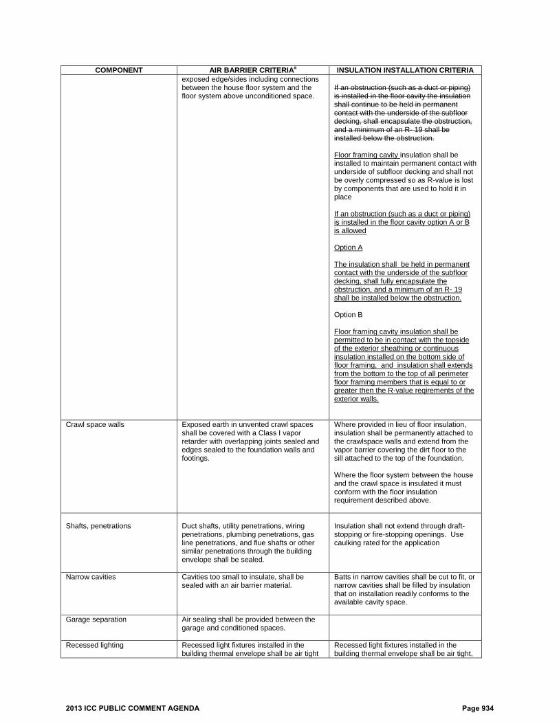
COMPONENT AIR BARRIER CRITERIAa INSULATION INSTALLATION CRITERIA exposed edge/sides including connections between the house floor system and the floor system above unconditioned space.
If an obstruction (such as a duct or piping) is installed in the floor cavity the insulation shall continue to be held in permanent contact with the underside of the subfloor decking, shall encapsulate the obstruction, and a minimum of an R- 19 shall be installed below the obstruction. Floor framing cavity insulation shall be installed to maintain permanent contact with underside of subfloor decking and shall not be overly compressed so as R-value is lost by components that are used to hold it in place If an obstruction (such as a duct or piping) is installed in the floor cavity option A or B is allowed Option A The insulation shall be held in permanent contact with the underside of the subfloor decking, shall fully encapsulate the obstruction, and a minimum of an R- 19 shall be installed below the obstruction. Option B Floor framing cavity insulation shall be permitted to be in contact with the topside of the exterior sheathing or continuous insulation installed on the bottom side of floor framing, and insulation shall extends from the bottom to the top of all perimeter floor framing members that is equal to or greater then the R-value reqirements of the exterior walls.
Crawl space walls Exposed earth in unvented crawl spaces shall be covered with a Class I vapor retarder with overlapping joints sealed and edges sealed to the foundation walls and footings.
Where provided in lieu of floor insulation, insulation shall be permanently attached to the crawlspace walls and extend from the vapor barrier covering the dirt floor to the sill attached to the top of the foundation. Where the floor system between the house and the crawl space is insulated it must conform with the floor insulation requirement described above.
Shafts, penetrations
Duct shafts, utility penetrations, wiring penetrations, plumbing penetrations, gas line penetrations, and flue shafts or other similar penetrations through the building envelope shall be sealed.
Insulation shall not extend through draft- stopping or fire-stopping openings. Use caulking rated for the application
Narrow cavities Cavities too small to insulate, shall be sealed with an air barrier material.
Batts in narrow cavities shall be cut to fit, or narrow cavities shall be filled by insulation that on installation readily conforms to the available cavity space.
Garage separation Air sealing shall be provided between the garage and conditioned spaces.
Recessed lighting Recessed light fixtures installed in the building thermal envelope shall be air tight
Recessed light fixtures installed in the building thermal envelope shall be air tight,
2013 ICC PUBLIC COMMENT AGENDA Page 934

COMPONENT AIR BARRIER CRITERIAa INSULATION INSTALLATION CRITERIA and sealed to the drywall. IC rated.
Plumbing and wiring All plumbing, ductwork, and wiring air
barrier penetrations shall be sealed. All penetration through the air barrier caused by running plumbing, ductwork, or wiring shall be sealed
Batt insulation shall be cut neatly to fit around obstructions (such as blocking or bridging), and split, installed, and/or fitted tightly around wiring, plumbing, ducting, and other services in the cavity, or insulation that on installation readily conforms to available space shall encapsulate any obstruction in the cavity.
Shower / tub on exterior wall Exterior walls adjacent to shower stalls, shower pans, and tubs shall have an air barrier installed separating conditioned space and the exterior wall insulation. Tub and shower drain trap penetrations through the subfloor shall be sealed with an air barrier material.
Exterior walls adjacent to showers and tubs shall be insulated.
Electrical / fan / phone box on exterior walls/ceilings
Electrical, communication, or other boxes located in exterior walls, ceilings, or floors shall be air tight boxes or shall be made to be air tight using air barrier material's Bath fan housing adjacent to and or installed in unconditioned spaces shall be sealed to the drywall and made air tight.
Insulation completely fills voids between the box and exterior sheathing
HVAC register boots HVAC supply or return registers/boots that penetrate the buildings thermal envelope shall be sealed to the subfloor or drywall.
Fireplace Exterior walls adjacent to fireplace enclosures shall have an air barrier installed encapsulating and separating interior conditioned space and exterior wall insulation. Fireplaces shall have tight fitting doors
Exterior walls adjacent to fireplaces shall be insulated.
a. In addition, inspection of log walls shall be in accordance with the provisions of ICC-400. Commenter’s Reason: Manufacturer instructions, best building practices, DOE's Building America program, Building Energy Code Programs, and other building educators all propose installing products and materials with best building practices and according to manufacturer instructions. However few go further than the code book to learn what best practices and manufactured instructions are. The intent of this new language is to clearly define air barrier and insulation requirements and installation practices that will lead to houses that can easily meet the air leakage standards of the energy code and ensure the performance of the stalled insulation materials.
The 2012 IECC also requires that insulation be installed correctly in order to comply with the air barrier requirements of the IECC. While it is important to install insulation correctly, this type of provision should not be linked to air sealing the house. This proposal provides two distinct sections to the table focused on either air sealing or insulation installation. It also provides a reference in the prescriptive requirements for insulation installation to the table.
Field experience shows that some trades continue to seal holes in the buildings enclosure with air permeable insulation, which is not best building practice does not meet manufacturers’ intents for the use of their products.
When the 2009 IECC was released many code officials were introduced to the importance of air barriers and are still struggling to understand where and how an air barrier is integral to the building enclosure. This new language will better prepare trades, builders, and code officials with how and where air barriers should be installed. The quality of the installation and enforcement should increase due to greater clarity and specificity.
The air barrier and insulation table included in the 2009 and 2012 IECC do not require a minimum level of insulation for corners and headers. The new requirement specifies a minimum insulation value and also includes interior wall intersections that also reduce the possibility for full wall insulation in these areas of the building.
Field practice has found kneewalls that are not enclosed on the exterior (attic) vertical plane exhibit more air infiltration and provide the opportunity for insulation to fall away from kneewalls over time reducing the efficiency of the overall building.
2013 ICC PUBLIC COMMENT AGENDA Page 935

Other field practices observed by raters include excessive compression of tabbed insulation batts when stapling the tabs to the side of the stud. This reduces insulation values and does not comply with manufacturer instructions. By adding this language to the table, insulation trades and others who install insulation will have a simplified description for installing batts and inset stapling.
This Public Comment corrects some of the concerns expressed by opponents of the proposal. RE76-13 Final Action: AS AM AMPC D
2013 ICC PUBLIC COMMENT AGENDA Page 936

RE79-13 Table R402.4.1.1 (IRC Table N1102.4.1.1)
Proposed Change as Submitted Proponent: Brian Dean ([email protected]), Energy Efficient Codes Coalition; Garrett Stone, Brickfield Burchette Ritts & Stone, PC; Jeff Harris, Alliance to Save Energy; Harry Misuriello, American Council for an Energy-Efficient Economy; and Bill Prindle, Energy Efficient Codes Coalition Revise as follows:
TABLE R402.4.1.1 (N1102.4.1.1) AIR BARRIER AND INSULATION INSTALLATION INSPECTION
(Portions of Table not shown remain unchanged) h. First value is cavity insulation, second is continuous insulation or insulated siding, so “13+5” means R-13 cavity insulation plus
R-5 continuous insulation or insulated siding. If structural sheathing covers 40 percent or less of the exterior, continuous insulation R-value shall be permitted to be reduced by no more than R-3 in the locations where structural sheathing is used – to maintain a consistent total sheathing thickness.
Reason: The purpose of this code change is to clarify and enhance compliance with and enforcement of the codes by organizing air barrier and insulation installation requirements into two separate checklists in the table. The proposal also updates and improves the language in the table to add clarity and to ensure that crucial elements of the thermal envelope are effectively sealed, installed and verified.
The proper installation of insulation and reasonable control of air leakage are both critical to achieving energy savings in homes. Although every building or dwelling unit is currently required to be tested for air leakage, a better-organized and more specific enumeration of key insulation and sealing requirements will lead to tighter, better-insulated, more energy efficient homes. The two columns are largely based on current insulation installation requirements and air barrier criteria in the 2012 IECC. We expect that as technology advances, and as building and inspection practices improve, this list will be updated. The reorganization of the requirements as presented above will facilitate that regular improvement in future code editions. Cost Impact: The code change proposal will not increase the cost of construction.
R402.4.1.1T #2-EC-DEAN-HARRIS-MISURIELLO-PRINDLE-STONE
Committee Action Hearing Results
Committee Action: Disapproved Committee Reason: Proponent recommended disapproval given action on RE63-13. Assembly Action: None
Individual Consideration Agenda
This item is on the agenda for individual consideration because a public comment was submitted. Public Comment: Brian Dean, ICF International, representing the Energy Efficient Codes Coalition; Jeff Harris, Alliance to Save Energy; Harry Misuriello, American Council for an Energy-Efficient Economy (ACEEE); Bill Prindle, representing the Energy Efficient Codes Coalition; Garrett Stone, Brickfield, Burchette, Ritts & Stone, PC; Donald J. Vigneau, Northeast Energy Efficiency Partnerships Inc., request Approval as Submitted. Commenter’s Reason: We recommend approval of RE79 as submitted for the reasons stated in our original reason statement. While RE63 moves the language addressed by RE79 from a footnote to code text and we have submitted a public comment for
2013 ICC PUBLIC COMMENT AGENDA Page 937

approval as modified on that proposal, if RE63 is not approved as modified, we will be requesting that this code change be adopted to remove the exception. RE79-13 Final Action: AS AM AMPC D
2013 ICC PUBLIC COMMENT AGENDA Page 938

RE80-13 Table R402.4.1.1 (IRC Table N1102.4.1.1)
Proposed Change as Submitted Proponent: Michael Schmeida, Divisional Manager-Sustainability and Government/Regulatory Affairs representing Tremco Commercial Sealants and Waterproofing, Beachwood, Ohio ([email protected]) Revise as follows:
TABLE R402.4.1.1 (N1102.4.1.1) AIR BARRIER AND INSULATION INSTALLATION
Component Criteria Garage separation
Air sealing and thermal separation shall be provided between the garage and conditioned space for all joints, service penetrations, and fenestrations.
(Portions of Table not shown remain unchanged.) Reason: 1. Sealing helps mitigate air movement into or out of the conditioned space, thereby reducing energy needs in mitigating
uncontrolled air movement. 2. Requiring insulation insures continuity in the thermal envelope and eliminates conductive transfer of energy through un-
insulated spaces. Cost Impact: The impact would be $500 depending on geography for a 2000/sqft home, but the ROI would be 3-5 years depending on region, design, etc.
R402.4.1.1T #2-EC-SCHMEIDA
Committee Action Hearing Results Committee Action: Disapproved Committee Reason: Rather than clarifying, the propose language provides unnecessary language to a provision that is presently understood. Assembly Action: None
Individual Consideration Agenda
This item is on the agenda for individual consideration because a public comment was submitted. Public Comment: Michael Schmeida, Divisional Manager-Sustainability and Government/Regulatory Affairs representing Tremco Commercial Sealants and Waterproofing, Beachwood, Ohio requests Approval as Modified by this Public Comment. Replace the proposal as follows:
TABLE R402.4.1.1 (N1102.4.1.1) AIR BARRIER AND INSULATION INSTALLATION
COMPONENT CRITERIA Garage separation
Air sealing shall be provided between the garage and conditioned spaces.
Batt insulation cut neatly to fit around, or insulation that on installation readily conforms to available space, shall be installed around any shaft or penetration through the thermal envelope.
2013 ICC PUBLIC COMMENT AGENDA Page 939
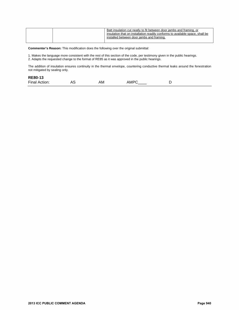
Batt insulation cut neatly to fit between door jambs and framing, or insulation that on installation readily conforms to available space, shall be installed between door jambs and framing.
Commenter’s Reason: This modification does the following over the original submittal: 1. Makes the language more consistent with the rest of this section of the code, per testimony given in the public hearings. 2. Adapts the requested change to the format of RE85 as it was approved in the public hearings. The addition of insulation ensures continuity in the thermal envelope, countering conductive thermal leaks around the fenestration not mitigated by sealing only. RE80-13 Final Action: AS AM AMPC D
2013 ICC PUBLIC COMMENT AGENDA Page 940

RE81-13 Table R402.4.1.1 (IRC N1102.4.1.1)
Proposed Change as Submitted Proponent: Michael Schmeida, Divisional Manager-Sustainability and Government/Regulatory Affairs representing Tremco Commercial Sealants and Waterproofing, Beachwood, Ohio ([email protected]) Revise as follows:
TABLE R402.4.1.1 (N1102.4.1.1) AIR BARRIER AND INSULATION INSTALLTION
COMPONENT CRITERIAa
Air barrier and thermal barrier
A continuous air barrier shall be installed in the building envelope. Exterior thermal envelope contains a continuous air barrier. Breaks or joints in the air barrier shall be sealed. Air-permeable insulation shall not be used as a sealing material.
Ceiling/attic
The air barrier in any dropped ceiling/soffit shall be aligned with the insulation and any gaps in the air barrier sealed. Access openings, drop down stair or knee wall doors to unconditioned attic spaces shall be sealed.
Walls
Corners and headers shall be insulated and the junction of the foundation and sill plate shall be sealed. The junction of the top plate and top of exterior walls shall be sealed. Exterior thermal envelope insulation for framed walls shall be installed in substantial contact and continuous alignment with the air barrier. Knee walls shall be sealed.
Windows, skylights and doors The space between window/door jambs and framing and skylights and framing shall be sealed on both the interior and exterior with a middle insulating layer filling the gap between the fenestration and framing/opening.
Rim joists Rim joists shall be insulated and include the air barrier.
Floors (including above-garage and cantilevered floors)
Insulation shall be installed to maintain permanent contact with underside of subfloor decking. The air barrier shall be installed at any exposed edge of insulation.
Crawl space walls
Where provided in lieu of floor insulation, insulation shall be permanently attached to the crawlspace walls. Exposed earth in unvented crawl spaces shall be covered with a Class I vapor retarder with overlapping joints taped.
Shafts, penetrations Duct shafts, utility penetrations, and flue shafts opening to exterior or unconditioned space shall be sealed.
Narrow cavities Batts in narrow cavities shall be cut to fit, or narrow cavities shall be filled by insulation that on installation readily conforms to the available cavity space.
Garage separation Air sealing shall be provided between the garage and conditioned spaces.
Recessed lighting Recessed light fixtures installed in the building thermal envelope shall be air tight, IC rated, and sealed to the drywall.
Plumbing and wiring Batt insulation shall be cut neatly to fit around wiring and plumbing in exterior walls, or insulation that on installation readily conforms to available space shall extend behind piping and wiring.
2013 ICC PUBLIC COMMENT AGENDA Page 941

Shower/tub on exterior wall Exterior walls adjacent to showers and tubs shall be insulated and the air barrier installed separating them from the showers and tubs.
Electrical/phone box on exterior walls The air barrier shall be installed behind electrical or communication boxes or air sealed boxes shall be installed.
HVAC register boots HVAC register boots that penetrate building thermal envelope shall be sealed to the subfloor or drywall.
Fireplace An air barrier shall be installed on fireplace walls. Fireplaces shall have gasketed doors.
a. In addition, inspection of log walls shall be in accordance with the provisions of ICC-400. Reason: 1. Installing a seal on both the interior and exterior side helps mitigate infiltration as well as exfiltration of air into or out of the wall
assembly, thereby reducing energy needs in mitigating uncontrolled air movement. 2. Requiring insulation insures continuity in the thermal envelope and eliminates conductive transfer of energy through un-
insulated spaces. Cost Impact: The cost would be negligible. R402.4.1.1T #3-EC-SCHMEIDA
Committee Action Hearing Results Committee Action: Disapproved Committee Reason: The provision as written provides for a scenario where the sealing method as configured could cause moisture problems. Assembly Action: None
Individual Consideration Agenda
This item is on the agenda for individual consideration because a public comment was submitted. Public Comment: Michael Schmeida, Divisional Manager-Sustainability and Government/Regulatory Affairs representing Tremco Commercial Sealants and Waterproofing, Beachwood, Ohio requests Approval as Modified by this Public Comment. Replace the proposal as follows:
TABLE R402.4.1.1 (N1102.4.1.1) AIR BARRIER AND INSULATION INSTALLTION
COMPONENT CRITERIAa
Windows, Skylights and Doors The space between window/door jambs and framing and skylights and framing
shall be sealed.
Batt insulation cut neatly to fit between window/door jambs and framing and skylights and framing, or insulation that on installation readily conforms to available space, shall be installed between window/door jambs and framing and skylights and framing.
a. In addition, inspection of log walls shall be in accordance with the provisions of ICC-400. (Portions of Table not shown remain unchanged) Commenter’s Reason: This modification does the following over the original submittal: 1. Makes the language more consistent with the rest of this section of the code, per testimony given in the public hearings. 2. Adapts the requested change to the format of RE85 as it was approved in the public hearings. The addition of insulation ensures continuity in the thermal envelope, countering conductive thermal leaks around the fenestration not mitigated by sealing only.
2013 ICC PUBLIC COMMENT AGENDA Page 942

RE81-13 Final Action: AS AM AMPC D
2013 ICC PUBLIC COMMENT AGENDA Page 943

RE82-13 Table R402.4.1.1 (IRC Table N1102.4.1.1)
Proposed Change as Submitted Proponent: Michael Schmeida, Divisional Manager-Sustainability and Government/Regulatory Affairs representing Tremco Commercial Sealants and Waterproofing, Beachwood, Ohio ([email protected]) Revise as follows:
Table R402.4.1.1 (N1102.4.1.1) AIR BARRIER AND INSULATION INSTALLATION
COMPONENT CRITERIA Shafts, penetrations
Duct shafts, utility penetrations and flue shafts opening to exterior or unconditioned space shall be sealed on both conditioned and unconditioned side of the opening with an insulating layer between the seals.
(Portions of Table not shown remain unchanged.) Reason: 1. Installing a seal on both the interior and exterior side helps mitigate infiltration as well as exfiltration of air into or out of the wall
assembly, thereby reducing energy needs in mitigating uncontrolled air movement. 2. Requiring insulation insures continuity in the thermal envelope and eliminates conductive transfer of energy through un-
insulated spaces. Cost Impact: The cost would be negligible.
R402.4.1.1T #4-EC-SCHMEIDA
Committee Action Hearing Results Committee Action: Disapproved Committee Reason: Consistent with committee’s disapproval of RE81-13. The proponent requested disapproval. Assembly Action: None
Individual Consideration Agenda
This item is on the agenda for individual consideration because a public comment was submitted. Public Comment: Michael Schmeida, Divisional Manager-Sustainability and Government/Regulatory Affairs representing Tremco Commercial Sealants and Waterproofing, Beachwood, Ohio requests Approval as Modified by this Public Comment. Replace the proposal as follows:
COMPONENT AIR BARRIER CRITERIA INSULATION INSTALLATION CRITERIA
Shafts, Penetrations Duct shafts, utility penetrations, and flue shafts opening to exterior or unconditioned space shall be sealed.
Batt insulation cut neatly to fit around, or insulation that on installation readily conforms to available space, shall be installed around any shaft or penetration through the thermal envelope.
2013 ICC PUBLIC COMMENT AGENDA Page 944

Commenter’s Reason: This modification does the following over the original submittal: 1. Makes the language more consistent with the rest of this section of the code, per testimony given in the public hearings. 2. Adapts the requested change to the format of RE85 as it was approved in the public hearings. The addition of insulation ensures continuity in the thermal envelope, countering conductive thermal leaks around the fenestration not mitigated by sealing only. RE82-13 Final Action: AS AM AMPC D
2013 ICC PUBLIC COMMENT AGENDA Page 945

RE83-13 Table R402.4.1.1 (IRC Table N1102.4.1.1)
Proposed Change as Submitted Proponent: Ellen Eggerton, representing Virginia Building and Code Officials Association Revise as follows:
TABLE R402.4.1.1 (N1102.4.1.1) AIR BARRIER AND INSULATION INSTALLATION
COMPONENT CRITERIAa
Walls
Cavities within corners and headers shall be insulated by completely filling the cavity with a material having a thermal resistance of R3 per inch minimum. and The junction of the foundation and sill plate shall be sealed. The junction of the top plate and top of exterior walls shall be sealed. Exterior thermal envelope insulation for framed walls shall be installed in substantial contact and continuous alignment with the air barrier. Knee walls shall be sealed.
(Portions of Table not shown remain unchanged) Reason: The current text says, “Corners and headers shall be insulated …” All headers and corners under all circumstances? Insulated to what level? This provision is a carryover of the 2009 IECC requirement. Varying answers to these questions have already lead to varying interpretations of the code requirements, uneven enforcement, and confusion in the regulated community. This proposal intends to allay some of that confusion by specifying that headers and corners must be insulated when there is an available cavity (e.g., a two-ply 2x header in a 2x4 wall leaves no cavity to fill) and by providing a practical definition of what insulated means in this context. Typical insulating materials like fiberglass and rigid foam can easily achieve R3 per inch. Cost Impact: There will be a cost impact from this proposal to the extent that this requirement was not previously enforced due to ambiguity in the requirement. Regardless, the quantities of insulation being installed are small, but there may be many of these areas to insulate, depending on the size, design, and layout of the proposed residential building.
R402.4.1.1T-EC-EGGERTON
Committee Action Hearing Results Committee Action: Approved as Modified Modify the proposal as follows: First sentence in “Criteria” column: Cavities within corners and headers of frame walls shall be insulated by completely filling the cavity with a material having a thermal resistance of R3 per inch minimum. Committee Reason: This a practical approach for an air barrier in corners and headers of frame walls. The modification is made to qualify where sealing is needed. Assembly Action: None
Individual Consideration Agenda
This item is on the agenda for individual consideration because a public comment was submitted.
2013 ICC PUBLIC COMMENT AGENDA Page 946

Public Comment: Don Surrena, CBO, representing the National Association of Home Builders, requests Approval as Modified by this Public Comment. Further modify the proposal as follows:
TABLE R402.4.1.1 (N1102.4.1.1) AIR BARRIER AND INSULATION INSTALLATION
COMPONENT CRITERIAa
Walls
Cavities within corners and headers shall be insulated by completely filling the cavity with a material having a thermal resistance of R3 per inch minimum. The junction of the foundation and sill plate shall be sealed. The junction of the top plate and top of exterior walls shall be sealed. Exterior thermal envelope insulation for framed walls shall be installed in substantial contact and continuous alignment with the air barrier. Knee walls shall be sealed.
(Portions of Table not shown remain unchanged) Commenter’s Reason: While filling the cavity with insulation can provide an energy benefit; once a specific R-value per inch is required, there is a responsibility by the builder and inspector to verify this value. Who is to say that the installed density of a loose fill or partial batt insulation meets the requirement? Nearly all insulating materials will typically meet this requirement but this may add to the confusion rather than solve any problem. The current language may create a situation where the builder uses “extra” wood as a nailer for siding or drywall (wood R-value approximately 1.25 per inch) and the interpretation is that it does not meet the requirements. Changing the language to simply “filling the cavity” meets the intent without burdening the code official to verify the R-value requirement and potentially argue over necessary framing members within the wall. RE83-13 Final Action: AS AM AMPC D
2013 ICC PUBLIC COMMENT AGENDA Page 947

RE88-13 R402.4.1.2 (IRC N1102.4.1.2), R402.4.1.2.1 (NEW) (IRC N1102.4.1.2.1 (NEW))
Proposed Change as Submitted
Proponent: Michael D. Fischer, Kellen Company, representing the Center for the Polyurethanes Industry ([email protected]) Revise as follows: R402.4.1.2 (N1102.4.1.2) Testing. The building or dwelling unit shall be tested by an approved agency and verified as having an air leakage rate of not exceeding 5 4 air changes per hour in Climate Zones 1 and 2, and 3 air changes per hour in Climate Zones 3 through 8. Testing shall be conducted with a blower door at a pressure of 0.2 inches w.g. (50 Pascals). Where required by the code official, testing shall be conducted by an approved third party. A written report of the results of the test shall be signed by the testing agency party conducting the test and provided to the code official. Testing shall be performed at any time after creation and sealing of all penetrations of the building thermal envelope. 402.4.1.2.1 (N1102.4.1.2.1) The air leakage rate in Climate Zones 3 through 8 shall be permitted to be no greater than 4 air changes per hour where all heating and conditioning ducts, air handlers, and filter boxes are located within the building thermal envelope. Reason: Building envelope tightness is a proven energy efficiency measure. With recent improvements in construction techniques and quality control, builders have demonstrated their ability to comply with air barrier requirements in the code as well as above-code programs. At the same time, the location of air handling ducts within the building thermal envelope has also become a more common and desirable construction technique- especially with new provisions for unvented attics in the IRC. This proposal offers a compromise that establishes a slight improvement in air barrier performance in the southern climate zones, as well as a trade-up in Climate Zones 3-8 that encourages the use of unvented attics. Cost Impact: This proposal may result in an increased initial construction cost in some climate zones depending upon the method of construction, but is likely to provide a short break-even point on energy consumption and utility costs.
R402.4.1.2-EC-FISCHER
Committee Action Hearing Results Committee Action: Disapproved
Committee Reason: This is would be a weakening of the code stringency. In addition, 3rd party testing is not necessary. Assembly Action: None
Individual Consideration Agenda
This item is on the agenda for individual consideration because a public comment was submitted. Public Comment: Michael Fischer, Kellen Company, representing the Center for the Polyurethanes Industry, requests Approval as Modified by this Public Comment. Modify the proposal as follows: R402.4.1.2 Testing. The building or dwelling unit shall be tested by an approved agency and verified as having an air leakage rate of not exceeding 5 4 air changes per hour in Climate Zones 1 and 2, and 3 air changes per hour in Climate Zones 3 through 8. Testing shall be conducted with a blower door at a pressure of 0.2 inches w.g. (50 Pascals). A written report of the results of the test
2013 ICC PUBLIC COMMENT AGENDA Page 948

shall be signed by the testing agency and provided to the code official. Testing shall be performed at any time after creation and sealing of all penetrations of the building thermal envelope. 402.4.1.2.1 The air leakage rate in Climate Zones 3 through 8 shall be permitted to be no greater than 4 air changes per hour where all heating and conditioning ducts, air handlers, and filter boxes are located within the building thermal envelope. Commenter’s Reason: This proposal originally contained two separate concepts: a requirement that blower door testing be performed by approved testing agencies and an ACH trade-off for buildings where the air movement system components are located within the thermal envelope. During the debate, there was a lack of consensus on the value of the trade-off. We are bringing this public comment forward without the trade-off, but preserving the concept that blower door testing be completed by an approved testing agency. The current code language establishes the use of an approved agency as an exception rather than the rule. Since producers of other components of the building thermal envelope are required to use third party entities to demonstrate compliance with test requirements, and the same requirement for testing by an approved agency should apply for testing of the building air barrier. The control of air leakage is the last line of defense against the transmission of heat through the building envelope; it is critical that the same consideration for insulation and fenestration be applied to the air barrier testing. RE88-13 Final Action: AS AM AMPC D
2013 ICC PUBLIC COMMENT AGENDA Page 949

RE90-13 R402.4.1.2 (IRC N1102.4.1.2), Table R405.5.2(1) (IRC Table N1105.5.2(1))
Proposed Change as Submitted Proponent: Don Surrena, CBO, representing National Association of Home Builders (NAHB) ([email protected]) Revise as follows: R402.4.1.2 (N1102.4.1.2) Testing. The building or dwelling unit shall be tested and verified as having an air leakage rate of not exceeding 5 air changes per hour in Climate Zones 1 and 2, and 3 4 air changes per hour in Climate Zones 3 through 8. Testing shall be conducted with a blower door at a pressure of 0.2 inches w.g. (50 Pascals). Where required by the code official, testing shall be conducted by an approved third party. A written report of the results of the test shall be signed by the party conducting the test and provided to the code official. Testing shall be performed at any time after creation of all penetrations of the building thermal envelope.
Table R405.5.2(1) (N1105.5.2(1) SPECIFICATIONS FOR THE STANDARD REFERENCE AND PROPOSED DESIGNS
BUILDING COMPONENT
STANDARD REFERENCE DESIGN PROPOSED DESIGN
Air exchange rate
Air leakage rate of 5 air changes per hour in Climate Zones 1 and 2, and 34 air changes per hour in Climate Zones 3 through 8 at a pressure of 0.2 inches w.g (50 Pa). The mechanical ventilation rate shall be in addition to the air leakage rate and the same as in the proposed design, but no greater than 0.01 × CFA + 7.5 × (Nbr + 1) where: CFA = conditioned floor area Nbr = number of bedrooms Energy recovery shall not be assumed for mechanical ventilation.
For residences that are not tested, the same air leakage rate as the standard reference design. For tested residences, the measured air exchange ratec. The mechanical ventilation rated shall be in addition to the air leakage rate and shall be as proposed.
(Portions of table not shown remain unchanged) Reason: Building tightness is an important part of an energy efficient and comfortable house; however, 3 air changes per hour at 50 Pascals is an extremely low target tightness especially for smaller homes. The ASHRAE Handbook of Fundamentals shows that less than 10% of new homes achieve 3 ACH or less. Four ACH is still an aggressive tightness level which will provide a tight, comfortable, energy efficient home for the consumer. Cost Impact: The code change proposal will not increase the cost of construction.
R402.4.1.2-EC-SURRENA
Committee Action Hearing Results Committee Action: Disapproved Committee Reason: This is a decrease in stringency relative to the 2012 IECC. Assembly Action: None
Individual Consideration Agenda
2013 ICC PUBLIC COMMENT AGENDA Page 950

This item is on the agenda for individual consideration because a public comment was submitted. Public Comment: Tim Ryan, representing the International Association of Building Officials requests As Modified by this Public Comment.
Table R405.5.2(1) (N1105.5.2(1) SPECIFICATIONS FOR THE STANDARD REFERENCE AND PROPOSED DESIGNS
BUILDING COMPONENT STANDARD REFERENCE DESIGN PROPOSED DESIGN
Air exchange rate
Air leakage rate of 5 air changes per hour in Climate Zones 1 and 2, and 4 air changes per hour in Climate Zones 3 through 8 at a pressure of 0.2 inches w.g (50 Pa). The mechanical ventilation rate shall be in addition to the air leakage rate and the same as in the proposed design, but no greater than 0.01 × CFA + 7.5 × (Nbr + 1) where: CFA = conditioned floor area Nbr = number of bedrooms Energy recovery shall not be assumed for mechanical ventilation.
For residences that are not tested, the same air leakage rate as the standard reference design. For tested residences, the measured air exchange ratec. The mechanical ventilation rated shall be in addition to the air leakage rate and shall be as proposed.
(Portions of table not shown remain unchanged) Commenter’s Reason: Building tightness is an important part of an energy efficient and comfortable house; however, 3 air changes per hour at 50 Pascals is an extremely low target tightness especially for smaller homes. Three air changes per hour not only is unusually tight, it also has the potential of causing indoor air quality problems if the ventilation systems are not installed or do not work properly. Five air changes per house is a reasonable air tightness rate that resembles a challenging but fair “minimum code” requirement. This requirement has been changed to 5 ACH in nearly every jurisdiction that has adopted the 2012 IECC including: Illinois, Utah, local jurisdictions in Kansas, Missouri. In addition states that are in the adoption process of the 2012 IECC are all considering increasing the air tightness up to 5 ACH50. RE90-13 Final Action: AS AM AMPC D
2013 ICC PUBLIC COMMENT AGENDA Page 951

RE93-13 R402.4.1.3 (NEW) (IRC N1102.4.1.3 (NEW))
Proposed Change as Submitted Proponent: Robby Schwarz, representing EnergyLogic, Inc. ([email protected]) Add new text as follows: R402.4.1.3 (N1102.4.1.3) Connection to Garage. The building or dwelling unit shall be tested and verified as being separate from an attached garage. While the blower door is being utilized to test the building or dwelling unit’s leakage rate, the connection between the dwelling unit and the garage shall also be tested. The pressure in the garage with reference to dwelling unit shall not be less than 45 Pascals relative to the dwelling unit when the dwelling unit pressure is at 50 Pascals relative to the outside. Reason: Separation between the house(dwelling unit) and garage is specifically called out on the air barrier and insulation table R402.4.1.1 yet it is unclear what is meant by this and why it is called out separately from the rest of the thermal envelops sealing that separates conditioned space from unconditioned space. The rational is an extension of efficiency into safety to ensure that pollutants and contaminants form the garage will not enter the home. A visual or written reference to this makes no sense when a test is available to ensure that separation has occurred. Testing is the only way to ensure safety and in extension greater efficiency. Cost Impact: The code change proposal will not increase the cost of construction.
R402.4.1.3 (NEW)-EC-SCHWARZ
Committee Action Hearing Results Committee Action: Disapproved Committee Reason: This proposal was not supported by technical justification related to the energy efficiency impact. In addition, no cost justification was provided. Assembly Action: None
Individual Consideration Agenda
This item is on the agenda for individual consideration because a public comment was submitted. Public Comment: Robby Schwarz, EnergyLogic, Inc., requests Approval as Modified by this Public Comment. Modify the proposal as follows: R402.4.1.3 (N1102.4.1.3) Connection to Garage. The building or dwelling unit shall be tested and verified as being separate from an attached garage. While the blower door is being utilized to test the building or dwelling unit’s leakage rate, the connection between the dwelling unit and the garage shall also be tested. The pressure in the garage with reference to dwelling unit shall not be less than 45 Pascals relative to the dwelling unit when the dwelling unit pressure is at 50 Pascals relative to the outside. The connection between the dwelling unit and the garage shall not be more than 10% of the total measured CFM@50 leakage of the dwelling unit. Commenter’s Reason: The link between efficiency and house tightness has been proven. The separation between the house (dwelling unit) and the garage is specifically called out in the air barrier and insulation table R402.4.1.1 largely due to the complexity of the framing and the difficulty and importance of sealing off the garage from the house. The code language, however, is unclear. Why is garage separation specifically called out separately from the rest of the thermal envelope and air barrier sealing that separates conditioned space from unconditioned space? In this location I believe the connection between life safety and energy efficiency is the reason to ensure that pollutants and contaminants from the garage will not enter the home and why specific consideration is given to separating the garage in the code. The problem is that a visual inspection cannot ensure separation and
2013 ICC PUBLIC COMMENT AGENDA Page 952

therefore cannot ensure efficiency or safety of the occupants. Testing is the only way to ensure safety and in extension greater efficiency. RE93-13 Final Action: AS AM AMPC D
2013 ICC PUBLIC COMMENT AGENDA Page 953

RE94-13 R402.4.3 (IRC N1102.4.3)
Proposed Change as Submitted Proponent: Jeff Inks, representing the Window & Door Manufacturers Association. Revise as follows: R402.4.3 (N1102.4.3) Fenestration air leakage. Windows, skylights and sliding glass doors shall have an air infiltration rate of no more than 0.3 cfm per square foot (1.5 L/s/m2), and swinging doors no more than 0.5 cfm per square foot (2.6 L/s/m2), when tested according to NFRC 400 or AAMA/ WDMA/CSA 101/I.S.2/A440 by an accredited, independent laboratory and listed and labeled by the manufacturer.
Exception: Site-built windows, skylights and doors.
Reason: This proposal is primarily a clean-up. The exception for site-built fenestration was removed from the commercial requirements during the last code development cycle as there is no justification for allowing it. These assemblies are required to meet the air leakage provisions of C402.4.3 for IECC commercial construction. Likewise, site-built windows, skylights and doors, if used in IECC residential construction, should meet the requirements of Section R402.4.3 without exception. Cost Impact: The code change proposal will not increase the cost of construction.
R402.4.3-EC-INKS
Committee Action Hearing Results Committee Action: Disapproved Committee Reason: The proposal was made with no cost justification. In addition this would remove flexibility for the builder from the code. Assembly Action: None
Individual Consideration Agenda
This item is on the agenda for individual consideration because public comments were submitted. Public Comment 1: Jeff Inks, Window & Door Manufacturers Association requests Approval as Submitted. Commenter’s Reason: As was pointed out in the proposal, the exception for site-built fenestration was removed from the commercial requirements during the last code development cycle as there is no justification for allowing it.
By definition (see below) site-built fenestration is still comprised of factory fabricated components. These assemblies are different from “field fabricated” (also see below) which are not comprised of factory fabricated components. Because “site-built” components are factory fabricated for a specific use/assembly, specimen units can be assembled and tested by the manufacturer which is why these assemblies are required to meet the air leakage provisions of C402.4.3 for IECC commercial construction. Likewise, site-built windows, skylights and doors, if used in IECC residential construction, should meet the requirements of Section R402.4.3 without exception.
Removing this exception also does not remove any flexibility with respect to using these products. It simply requires for them to also meet the air leakage requirements which for the reasons stated above is reasonable.
Concerns regarding limits on flexibility can be addressed by making the exception applicable to field fabricated products. “FENESTRATION PRODUCT, SITE-BUILT. A fenestration designed to be made up of field-glazed or field-assembled units using specific factory cut or otherwise factory formed framing and glazing units. Examples of site-built fenestration include storefront systems, curtain walls, and atrium roof systems. “ “FENESTRATION PRODUCT, FIELD-FABRICATED. A fenestration product whose frame is made at the construction site of standard dimensional lumber or other materials that were not previously cut, or otherwise formed with the specific intention of being used to fabricate a fenestration product or exterior door. Field fabricated does not include site-built fenestration. “
2013 ICC PUBLIC COMMENT AGENDA Page 954

Public Comment 2: Jeff Inks, Window & Door Manufacturers Association requests Approval as Modified by this Public Comment. Modify the proposal as follows: R402.4.3 Fenestration air leakage. Windows, skylights and sliding glass doors shall have an air infiltration rate of no more than 0.3 cfm per square foot (1.5 L/s/m2), and swinging doors no more than 0.5 cfm per square foot (2.6 L/s/m2), when tested according to NFRC 400 or AAMA/ WDMA/CSA 101/I.S.2/A440 by an accredited, independent laboratory and listed and labeled by the manufacturer.
Exception: Field-fabricated windows, skylights and doors.
IECC SECTION R202 (IRC N1101.9)
GENERAL DEFINITIONS FENESTRATION PRODUCT, FIELD-FABRICATED. A fenestration product whose frame is made at the construction site of standard dimensional lumber or other materials that were not previously cut, or otherwise formed with the specific intention of being used to fabricate a fenestration product or exterior door. Field fabricated does not include site-built fenestration. Commenter’s Reason: This public comment addresses the committee’s concern that deleting the air leakage exception for “site-built” fenestration would remove flexibility for the builder. This modification simply replaces “Site-built” with “Field-fabricated” and adds the “Field-fabricated” definition already established in the commercial provisions of the IECC.
For the reasons stated below, we do not believe an exception for “site-built” products as defined by the IECC is warranted. Approval of this proposal as modified by this public comments actually adds an exception that technically does not exist currently so it should improve the flexibility rather than restrict it.
Regarding removal of the exception for “site-built”, as was pointed out in the original proposal, the exception for site-built fenestration was removed from the commercial requirements during the last code development cycle as there is no justification for allowing it.
By definition (see below) site-built fenestration is still comprised of factory fabricated components. These assemblies are different from “field fabricated” ( as defined by the IECC and proposed for inclusion in the residential provisions) which are not comprised of factory fabricated components. Because “site-built” components are factory fabricated for a specific use/assembly, specimen units can be assembled and tested by the manufacturer which is why these assemblies are required to meet the air leakage provisions of C402.4.3 for IECC commercial construction. Likewise, site-built windows, skylights and doors, if used in IECC residential construction, should meet the requirements of Section R402.4.3 without exception.
Removing this exception also does not remove any flexibility with respect to using these products. It simply requires for them to also meet the air leakage requirements which for the reasons stated above is reasonable.
Concerns regarding limits on flexibility can be addressed by making the exception applicable to field fabricated products. “FENESTRATION PRODUCT, SITE-BUILT. A fenestration designed to be made up of field-glazed or field-assembled units using specific factory cut or otherwise factory formed framing and glazing units. Examples of site-built fenestration include storefront systems, curtain walls, and atrium roof systems. “ “FENESTRATION PRODUCT, FIELD-FABRICATED. A fenestration product whose frame is made at the construction site of standard dimensional lumber or other materials that were not previously cut, or otherwise formed with the specific intention of being used to fabricate a fenestration product or exterior door. Field fabricated does not include site-built fenestration. “ RE94-13 Final Action: AS AM AMPC D
2013 ICC PUBLIC COMMENT AGENDA Page 955

RE95-13 R402.5 (IRC N1102.5)
Proposed Change as Submitted Proponent: Craig Conner, Building Quality, representing self ([email protected]); Dr. Thomas D. Culp, Birch Point Consulting LLC, representing the Glazing Industry Code Committee ([email protected]) Delete without substitution: R402.5 (N1102.5) Maximum fenestration U -factor and SHGC (Mandatory). The area-weighted average maximum fenestration U-factor permitted using tradeoffs from Section R402.1.4 or R405 shall be 0.48 in Climate Zones 4 and 5 and 0.40 in Climate Zones 6 through 8 for vertical fenestration, and 0.75 in Climate Zones 4 through 8 for skylights. The area-weighted average maximum fenestration SHGC permitted using tradeoffs from Section R405 in Climate Zones 1 through 3 shall be 0.50. Reason: CONNER: The limits on U-factor and SHGC trade offs reduce flexibility without any compensating energy savings. A decrease in the energy efficiency of the windows through the performance calculation would have to be made up elsewhere leaving the resulting energy efficiency, so the energy result is neutral.
Given the stringency of the newer codes, this section mostly adds a bit of confusion to the code. The statement of a limit on trade offs is sometimes confused with the actual requirement itself (in Table R402.1). There is no need to bulk up the code with even small statements that seldom have any impact. CULP: By definition, trade-offs are energy neutral, so these mandatory “hard limits” save no energy, but set artificial constraints that limit design flexibility and innovation. Practically speaking, the vast majority of “normal” windows already meet these criteria, so this section has little real impact, and only serves to (a) add confusion between these numbers and the real requirements in Table R402.1.1, and (b) cause compliance problems for unique or special applications.
For example, glass block used in a bathroom remodel: … it has no label, so use the default U-factor and SHGC … but the default values do not meet Table R402.1.1, so use a trade-off … but the default values do not meet the hard limits in this section R402.5, so use area-weighted averaging … but there is nothing else in the remodel to area-weight average.
So it becomes effectively illegal, even if there are other trade-offs that make the overall remodel even more energy efficient, and
the only recourse is to seek a special allowance through the alternative methods provision. This is just one example. What about special products used in tornado storm shelters that won’t meet the U-factor hard limit?
What about vacuum glazing that meets the U-factor and greatly exceeds the required energy efficiency, but not the SHGC hard limit? Do we want to discourage vacuum glazing?
Granted, these are not common situations, but what have we accomplished by creating artificial barriers and extra headaches for code officials and builders? This section should be removed. Cost Impact: The code change proposal will not increase the cost of construction. R402.5-EC-CONNER-CULP
Committee Action Hearing Results Committee Action: Disapproved Committee Reason: Maximums U-Factors and SHGC are needed to avoid issues with peak demand and moisture. This is an important “backstop” to assure minimum levels of envelope integrity. These minimums are used widely, and have been for several years. Assembly Action: None
Individual Consideration Agenda
This item is on the agenda for individual consideration because public comments were submitted.
2013 ICC PUBLIC COMMENT AGENDA Page 956

Public Comment 1: Dr. Thomas D. Culp, Birch Point Consulting LLC, representing Glazing Industry Code Committee requests Approval as Submitted. Commenter’s Reason: We ask that you overturn the recommendation from the committee for disapproval, which was a split decision, and approve RE95 as-submitted. Much of the discussion at the code hearings has been about how to provide flexibility while upholding energy performance. Section R402.5 is completely counter to that goal and should be removed, as specified in this proposal. Even if you prove equivalent or better energy performance in the performance path, Section R402.5 adds an artificial barrier to the use of certain products and designs. For the vast majority of “normal” windows this section is not a problem, so this section is not actually doing anything significant, yet it causes compliance problems for unique or special applications. Examples of how Section R402.5 creates compliance problems are given in the original reason statement. Some additional examples include commercial-type entrance doors in the lobby of an apartment building, or fire-rated curtain wall type entrance and stairways in a dormitory. These special applications will typically not meet the basic prescriptive criteria, and even if adjustments are made to the building design to show equivalent or better overall energy efficiency in the performance path, section R402.5 will still prevent them from being installed. The only recourse is to seek use of the alternative means and methods provision, which just creates more work for the code official and delay for the builder. This section causes problems, does not save any energy, and should be removed. We ask that you vote “NO” on the initial motion for disapproval, and then to vote “YES” on a motion to approve RE95 as-submitted. Public Comment 2: Vickie Lovell, Intercode, Inc., representing International Window Film Association requests Approval as Submitted. Commenter’s Reason: Limits on fenestration U-factor and SHGC trade-offs do not promote flexibility and place needless and unfair restrictions on how code compliance can be achieved. It is an impediment to design innovation and opportunities for cutting edge technologies on building components, which is the opposite of promoting whole building energy performance. More importantly, it causes confusion to designers, code officials and all other users of the code by overcomplicating it. It creates a subset of prescriptive requirements in the performance path which is inappropriate and is not consistent with the intent of the performance objectives of this section of the code. RE95-13 Final Action: AS AM AMPC D
2013 ICC PUBLIC COMMENT AGENDA Page 957

RE96-13 R402.5 (IRC N1102.5)
Proposed Change as Submitted Proponent: Brian Dean, Energy Efficient Codes Coalition; Garrett Stone, Brickfield Burchette Ritts & Stone, PC; Jeff Harris, Alliance to Save Energy; Harry Misuriello, American Council for an Energy-Efficient Economy; and Bill Prindle, Energy Efficient Codes Coalition Revise as follows: R402.5 (N1102.5) Maximum fenestration U-factor and SHGC (Mandatory). The area-weighted average maximum fenestration U-factor permitted for vertical fenestration products when complying with this code using trade offs from under Section R402.1.4 or Section R405 shall not exceed the U-factor specified in Table R402.1.1 by more than 25% be 0.48 in Climate Zones 4 and 5 and 0.40 in Climate Zones 6 through 8 for vertical fenestration, and 0.75 in Climate Zones 4 through 8 for skylights. The area-weighted average U-factor for skylights when complying with this code under Section R402.1.4 or Section R405 shall not exceed the U-factor specified in Table R402.1.1 by more than 25%. The area-weighted average maximum fenestration SHGC permitted for all fenestration products when complying with this code under using trade-offs from Section R405 shall not exceed the SHGC specified in Table R402.1.1 by more than 50%in Climate Zones 1 through 3 shall be 0.50. Reason: The purpose of this code change is to modify the requirements and clarify the language related to the maximum U-factor and SHGC for fenestration when using trade-offs for code compliance. This revision improves the energy efficiency and usability of the energy code by ensuring that as prescriptive fenestration efficiency requirements change, the mandatory fenestration maximums (for trade-offs) will automatically adjust as well, specifically by setting the maximum weighted average U-factor at 25% above the prescriptive value and the SHGC at 50% above the prescriptive value. In addition, the revision improves and clarifies the language in the section.
For nearly a decade, the current version of the fenestration U-factor and SHGC maximums in Section R402.5 have provided an effective and critical backstop for fenestration efficiency trade-offs under the Total UA compliance path and the Simulated Performance Alternative. This section ensures that fenestration, which is a crucial element in the thermal envelope, particularly from the standpoint of comfort, as well as condensation, energy efficiency and HVAC sizing, will not be overly weakened by trade-offs.
Unfortunately, as prescriptive fenestration U-factors and SHGC requirements have improved substantially over the last few code change cycles, the fenestration maximums have remained unchanged. For example:
• In the 2006 IECC, the prescriptive SHGC requirement in climate zone 3 was 0.40 and the SHGC maximum in trade-offs was 0.50 (25% higher than the prescriptive value).
• In the 2009 IECC, the prescriptive SHGC requirement was improved to 0.30, but the SHGC maximum remained at 0.50 (67% higher).
• In the 2012 IECC, the prescriptive SHGC requirement was further improved to 0.25, but the SHGC maximum remained at 0.50 (100% higher).
The proposal sets the maximum area-weighted average U-factor 25% higher and the SHGC 50% higher than the prescriptive value, giving a reasonable (but not unlimited) amount of flexibility to the design professional. We chose 25% for U-factor and 50% for SHGC based on judgment after reviewing the resulting values, in recognition that prescriptive U-factors tend to be greater than prescriptive SHGC values, justifying a smaller percentage, and reflecting the need for more flexibility for SHGC due to passive solar concerns. The following table shows the effect of this new proposal on the maximum values for vertical windows: Climate Zone Prescriptive U-
factor Maximum U-
factor Current Maximum U-
factor Proposed
Prescriptive SHGC
Maximum SHGC
Current
Maximum SHGC
Proposed 1 NR NR NR 0.25 0.50 0.38 2 0.40 NR 0.50 0.25 0.50 0.38 3 0.35 NR 0.44 0.25 0.50 0.38 4 0.35 0.48 0.44 0.40 NR 0.60 5 0.32 0.48 0.40 NR NR NR
6 - 8 0.32 0.40 0.40 NR NR NR
The proposal also applies a uniform backstop percentage over all climate zones, improving efficiency and simplifying compliance and enforcement in states that stretch across multiple climate zones. The new maximums also allow considerable flexibility for innovative designs such as passive solar, because individual or multiple windows may have significantly higher SHGC
2013 ICC PUBLIC COMMENT AGENDA Page 958

or U-factor values, as long as they achieve an area-weighted average value that is within a reasonable range of the prescriptive values.
Because the Total UA and Simulated Performance Alternative compliance options are typically software-based, the change to a percentage-based maximum should require no additional effort on the part of the builder or design professional. Over the long run, this proposal will simplify the code, improve energy efficiency, and add consistency because the maximum will automatically track any change to the fenestration U-factor or SHGC requirements.
The fenestration trade-off limits currently found in the residential chapter of the IECC are simple, mandatory measures that ensure all new buildings contain high-quality, cost-effective windows that save energy, provide reasonable comfort, resist condensation in colder climates and block unwanted solar gain in warmer climates. Without the protection of this backstop, fenestration values could be traded away to levels unacceptable in modern building practice. Given the improvements to window efficiency brought about by the 2012 IECC and our nation’s high priority for energy efficiency, this proposal is a common-sense improvement to an effective code requirement.
• Simple compliance. The residential fenestration maximums are effective and easy to understand. These requirements have been successfully applied for the last several years. All states that have already adopted the 2006, 2009, and 2012 IECC have adopted these maximums to residential construction. They are also already seamlessly built into compliance software such as the Department of Energy’s REScheck.
• Flexible standard. The area-weighted average approach embodied in the fenestration maximums allows considerable flexibility for the use of decorative glass, glass block, and other fenestration products, while maintaining a baseline performance for the building’s overall glazing. In short, not all products are required to individually meet the maximum values; only the area-weighted average of all products in the building are required to meet the maximum values specified in this code provision.
• Quality windows, energy savings and peak demand savings nationwide. The fenestration maximums encourage the use of cost-effective energy-efficient windows nationwide. Because good windows reduce energy consumption both during peak cooling times in the summer months and during peak heating hours in the winter months, such windows help to reduce the strain on the electric grid and natural gas pipeline system and delay the need to build expensive peaking facilities. By reducing the trade-off of efficient windows for other measures, the maximums better capture the benefits of blocking solar gain and providing reasonable insulating value such as peak reduction, reduced cooling system sizes and year-round comfort. Consumers also enjoy the reduced costs that come with economies of scale and market transformation.
• More comfortable buildings and less energy use. Incremental changes in window efficiency can have a huge impact on occupant comfort because even the most efficient windows are, at best, still only the equivalent of about an R-3 wall in the winter. Moreover, unlike the opaque wall, even the best fenestration allows substantial summer solar heat gain into the conditioned space. Hot spots created by high solar gain in the summer and/or cold or drafty glass in the winter months can force an occupant to adjust the thermostat to compensate. A good window will provide reasonable insulating value, keeping occupants more comfortable during the coldest months. Similarly, windows with low SHGC will protect against hot spots and occupant discomfort, and will make it less likely that occupants will need to adjust the thermostat and use more energy.
For a more detailed discussion of the benefits of good fenestration, see the section on the benefits of efficient windows on the
website of the Efficient Windows Collaborative (a Collaborative of the Alliance to Save Energy, the University of Minnesota, Center for Sustainable Building Research and Lawrence Berkeley National Laboratory, with support from the U.S. Department of Energy) -- http://www.efficientwindows.org/benefits.cfm.
The fenestration maximums have served an important role in ensuring residential energy efficiency for many years. We recommend that the proposed improvements to the fenestration maximums be adopted. Cost Impact: The code change proposal will not increase the cost of construction.
R402.5-EC-DEAN-HARRIS-MISURIELLO-PRINDLE-STONE
Committee Action Hearing Results Committee Action: Disapproved Committee Reason: The proponent did not demonstrate the technical merits of this proposal in a justifiable manner. Assembly Action: None
Individual Consideration Agenda
This item is on the agenda for individual consideration because public comments were submitted. Public Comment 1:
2013 ICC PUBLIC COMMENT AGENDA Page 959

Jeff Inks, Window & Door Manufacturers Association requests Approval as Submitted. Commenter’s Reason: The variance between the prescriptive fenestration requirements and the trade-off cap limits need to remain consistent from edition to edition of the IECC in order to ensure the code is not inadvertently weakened as the proponents have pointed out.
Establishing the caps as a percentage of the respective prescriptive requirements is a much more sensible approach for ensuring the variance remains consistent than prescribing specific values because it alleviates the need for additional revisions to the cap values when prescriptive requirements are amended.
We also believe the technical merits of this approach are clear and have been clearly demonstrated by the proponent and in addition, that the basis for the proposed variance of 25% for U-factor and 50% for SHGC is sound. Public Comment 2: Brian Dean, ICF International, representing the Energy Efficient Codes Coalition; Jeff Harris, Alliance to Save Energy; Harry Misuriello, American Council for an Energy-Efficient Economy (ACEEE); Bill Prindle, representing the Energy Efficient Codes Coalition; Garrett Stone, Brickfield, Burchette, Ritts & Stone, PC; Donald J. Vigneau, Northeast Energy Efficiency Partnerships Inc., request Approval as Modified by this Public Comment. Modify the proposal as follows: R402.5 (N1102.5) Maximum fenestration U-factor and SHGC (Mandatory). The area-weighted average U-factor for vertical fenestration products when complying with this code under Section R402.1.4 or Section R405 shall not exceed 0.40 in climate zones 4 through 8 the U-factor specified in Table R402.1.1 by more than 25%. The area-weighted average U-factor for skylights when complying with this code under Section R402.1.4 or Section R405 shall not exceed 0.65 in climate zones 4 through 8 the U-factor specified in Table R402.1.1 by more than 25%. The area-weighted average SHGC for all fenestration products when complying with this code under Section R405 shall not exceed 0.40 in climate zones 1 through 3 the SHGC specified in Table R402.1.1 by more than 50%. Commenter’s Reason: We recommend approval of RE96 as modified by this public comment. RE96 as modified will bring about a reasonable update to the fenestration maximums that have been in the IECC for many years. The importance of the current fenestration maximums was recognized by the committee in recommending disapproval of RE95. The committee found: “Maximums U-Factors and SHGC are needed to avoid issues with peak demand and moisture. This is an important “backstop” to assure minimum levels of envelope integrity. These minimums are used widely, and have been for several years.” The reason statement for the original RE96 also explains the benefits of the current requirements and the need to update in more detail.
Although we continue to believe that RE96 as submitted would provide long-term benefits by allowing the caps to automatically update whenever fenestration requirements are altered in the IECC, some concern was raised at the committee hearings about the use of a percentage instead of a fixed value. In order to provide additional clarity, we have modified the proposal to establish specific values for specific climate zones, and we have limited the reach of the proposal to only those climate zones covered by the fenestration maximums in the 2012 IECC. The U-factors selected as maximums reflect the prescriptive U-factors already established in milder climate zones (see Table R402.1.1). If a 0.40 U-factor is appropriate and cost effective for warm climate zone 2 in the current IECC, it is reasonable to set 0.40 as a trade-off limit or maximum in the much colder climates of zones 4 – 8. Similarly, if 0.40 SHGC is reasonable in the mixed climate zone 4, it is reasonable to set 0.40 SHGC as a maximum in the cooling-dominated climate zones 1 – 3. It should also be noted that these values are also reasonably consistent with those that would be produced by RE96, as submitted.
Regardless of whether ICC membership favors the original or the modified proposal, we believe that an update to the fenestration maximums is overdue. If the permanent fix provided by the original RE96 is not adopted, we recommend the modifications in this public comment to provide a one-time update to the fenestration maximums. Public Comment 3: R. Christopher Mathis, MC2 Mathis Consulting Company, requests Approval as Modified by this Public Comment. Modify the proposal as follows: R402.5 (N1102.5) Maximum fenestration U-factor and SHGC (Mandatory). The area-weighted average maximum fenestration building component U-factor and SHGC permitted using tradeoffs from Section R402.1.4 or Section R405 shall not exceed the values in Table R402.5.1. be 0.48 in Climate Zones 4 and 5 and 0.40 in Climate Zones 6 through 8 for vertical fenestration, and 0.75 in Climate Zones 4 through 8 for skylights. The area-weighted average maximum fenestration SHGC permitted using tradeoffs from Section R405 in Climate Zones 1 through 3 shall be 0.50.
2013 ICC PUBLIC COMMENT AGENDA Page 960

Item
DOE Core Data
Book1
NAHB
Report2
NIBS
Report3
ASHRAE Handbook HVAC
Applications4 Envelope (Years) (Years) (Years) (Years)
Insulation 100 100 100 ‐ Windows 40 30 50 ‐
HVAC Furnace, Forced Air 14 17.5 18 18 Unit Heaters, Gas or Electric 15 17.5 13 13 Heat Pump 12 16 15 15 Air Conditioner ‐ 12.5 ‐ ‐ Central Air 11 15 15 15 Window Unit 9 10 10 10 Water Heater, Electric 13 11 14 ‐ Water Heater, Gas 11 10 12 ‐
TABLE 402.5.1 Maximum Building Component U-factors and Maximum Fenestration SHGC
When Complying Under Sections R402.1.4 or R405
Commenter’s Reason: Building officials need some assurance that the trades allowed in 402.1.4 and 405 do not result in deficient building envelopes. This modification addresses this need by inserting a simple table defining the allowed limits on envelope trades. This table provides a “backstop” of protection, building upon the protective structure that already exists in R402.5. The proposal also protects against intentional or accidental “gaming” that can occur when seeking compliance via the UA tradeoff or performance path modeling approaches (Sections R402.1.4 and R405, respectively). This proposal provides a simple table of prescriptive envelope performance requirements in a code‐familiar structure. It defines maximum allowed limits on envelope components when compliance is sought under R402.1.4 or R405. The maximum component values in the table are based on: 1. A 15% increase in U‐factor (reductions in envelope efficiency) versus the 2012 IECC , and 2. A 25% increase in SHGC versus the 2012 IECC (as proposed in RE96).
Why is it important to insert these trading limitations? The code focus is “effective use of energy… over the useful life of the building” (2012 IECC. Sections C101.3 and R101.3.) However, nowhere in this code is this critical code objective – “over the useful life of the building” – addressed.
RE96 (AMPC)-MATHIS Envelope decisions often remain with the building for the life of the building. Numerous studies have investigated the “useful life” of various residential building materials, components and systems. Data from four such studies has been summarized below for building components relevant to Section 402.5.
1 U.S. Department of Energy. 2011 Buildings Energy Data Book. D&R International, Ltd. March 2012.
2 National Association of Home Builders. Study of Life Expectancy of Home Components. February 2007 3 U.S. Department of Housing and Urban Development. Residential Rehabilitation Inspection Guide. By the
National Institute of Building Sciences. February 2000. 4 “ASHRAE Handbook Heating, Ventilating, and Air‐Conditioning Applications”, ASHRAE Inc., 2011.
Climate Zone
Fenestration
U-Factor
Fenestration
SHGC
Skylight U-Factor
Ceiling
U-Factor
Frame Wall
U-Factor
Mass Wall U-Factor
Floor
U-Factor
Basement Wall
U-Factor
Crawlspace Wall
U-Factor 1 0.58 0.31 0.86 0.040 0.094 0.227 0.074 0.414 0.549
2 0.46 0.31 0.75 0.035 0.094 0.190 0.074 0.414 0.549
3 0.40 0.31 0.63 0.035 0.066 0.113 0.054 0.105 0.156
4 except Marine 0.40 0.50 0.63 0.030 0.066 0.113 0.054 0.068 0.075
5 and Marine 4 0.37 ‐ 0.63 0.030 0.066 0.094 0.038 0.058 0.063
6 0.37 ‐ 0.63 0.030 0.055 0.069 0.038 0.058 0.063
7 and 8 0.37 ‐ 0.63 0.030 0.055 0.066 0.032 0.058 0.063
2013 ICC PUBLIC COMMENT AGENDA Page 961

As one can easily see, different building elements have dramatically different life expectancies, especially when considering the 100+ year life expectancy of the home.
Long‐lasting building envelope decisions (insulation, windows, air sealing, etc.) define most of the heating and cooling loads of the building. Shorter‐lived HVAC systems must then be sized and selected to meet those loads. Even shorter‐lived hot water and lighting systems figure into the computer models and should also be weighed against the more durable envelope provisions.
For these reasons it is appropriate to have code requirements that ensure some basic levels of envelope component efficiency when using the tradeoff approaches in R402.1.4 and R405.
Currently, Section R402.5 is the only section providing protection against unreasonable UA or performance modeling trades. This proposal SIMPLIFIES that protection for the whole building envelope, not just the windows. Without such protection the code will continue to treat every building decision as though they have EQUAL life expectancies.
This table provides code officials a simple means to check the values proposed for code compliance under R402.1.4 and R405. These protections in the code are becoming ever more important as computer modeling and rating programs become more the norm for energy code compliance. IF these types of “trades” are to be allowed, they must be informed by our understanding of building product and component life expectancy, and have reasonable limits applied as appropriate. This proposal provides much‐needed protection against dumb mathematical trades that MAY work in computer programs, but result in risks to the most basic goal of this code – “effective use of energy… for the useful life of the building”.
RE96-13 Final Action: AS AM AMPC D
2013 ICC PUBLIC COMMENT AGENDA Page 962

RE99-13 R403.1 (IRC N1103.1), R403.1.1 (IRC N1103.1.1), R403.1.2 (IRC N1103.1.2), R403.2.1 (IRC N1103.2.1), R403.2.2 (N1103.2.2), R403.2.3 (IRC N1103.2.3), R403.2.4 (NEW) (IRC N1103.2.4 (NEW)), R403.2.2.1 (IRC N1103.2.2.1), R403.2.6 (NEW), (IRC N1103.2.6 (NEW), Table R405.2(1) (IRC Table N1105.2(1))
Proposed Change as Submitted Proponent: Brian Dean, Energy Efficient Codes Coalition; Garrett Stone, Brickfield Burchette Ritts & Stone, PC; Jeff Harris, Alliance to Save Energy; Harry Misuriello, American Council for an Energy-Efficient Economy; and Bill Prindle, Energy Efficient Codes Coalition. Revise as follows: R403.1 (N1103.1) Controls (Mandatory). At least one thermostat shall be provided for each separate heating and cooling system. Heating and cooling system controls shall comply with Sections R403.1.1 through R403.1.3.
R403.1.1 (N1103.1.1) Thermostat (Mandatory). Not less than one thermostat shall be provided for each separate heating and cooling system. R403.1.1 (N1103.1.1) R403.1.2 (N1103.1.2) Programmable thermostat (Mandatory). Where the primary heating system is a forced-air furnace, at least one thermostat per dwelling unit shall be capable of controlling the heating and cooling system on a daily schedule to maintain different temperature set points at different times of the day. This thermostat shall include the capability to set back or temporarily operate the system to maintain zone temperatures down to 55ºF (13ºC) or up to 85ºF (29ºC). The thermostat shall initially be programmed with a heating temperature set point not higher than 70ºF (21ºC) and a cooling temperature set point not lower than 78ºF (26ºC). R403.1.2 (N1103.1.2) R403.1.3 (N1103.1.3) Heat pump supplementary heat (Mandatory). Heat pumps having supplementary electric-resistance heat shall have controls that, except during defrost, prevent supplemental heat operation when the heat pump compressor can meet the heating load.
R403.2 (N1103.2) Ducts. Ducts and air handlers shall be sealed, tested for leakage and insulated in accordance with Sections R403.2.1 through R403.2.36.
R403.2.1 (N1103.2.1) Insulation (Prescriptive). Supply ducts in attics shall be insulated to a minimum of R-8. All other ducts shall be insulated to a minimum of R-6.
Exception: Ducts or portions thereof located completely inside the building thermal envelope.
R403.2.1 (N1103.2.1) Building cavities (Mandatory). Building framing cavities shall not be used as ducts or plenums. R403.2.2 (N1103.2.2) Sealing (Mandatory). Ducts, air handlers, and filter boxes shall be sealed. Joints and seams shall comply with either the International Mechanical Code or International Residential Code, as applicable.
Exceptions:
1. Air-impermeable spray foam products shall be permitted to be applied without additional joint seals.
2013 ICC PUBLIC COMMENT AGENDA Page 963

2. Where a duct connection is made that is partially inaccessible, three screws or rivets shall be equally spaced on the exposed portion of the joint so as to prevent a hinge effect. 3. Continuously welded and locking-type longitudinal joints and seams in ducts operating at static pressures less than 2 inches of water column (500 Pa) pressure classification shall not require additional closure systems.
Duct tightness shall be verified by either of the following: 1. Postconstruction test: Total leakage shall be less than or equal to 4 cfm (113.3 L/min) per 100
square feet (9.29 m2) of conditioned floor area when tested at a pressure differential of 0.1 inches w.g. (25 Pa) across the entire system, including the manufacturer’s air handler enclosure. All register boots shall be taped or otherwise sealed during the test.
2. Rough-in test: Total leakage shall be less than or equal to 4 cfm (113.3 L/min) per 100 square feet (9.29 m2) of conditioned floor area when tested at a pressure differential of 0.1 inches w.g. (25 Pa) across the system, including the manufacturer’s air handler enclosure. All registers shall be taped or otherwise sealed during the test. If the air handler is not installed at the time of the test, total leakage shall be less than or equal to 3 cfm (85 L/min) per 100 square feet (9.29 m2) of conditioned floor area. Exception: The total leakage test is not required for ducts and air handlers located entirely within the building thermal envelope.
R403.2.3 (N1103.2.3)Building cavities (Mandatory). Building framing cavities shall not be used as ducts or plenums. R403.2.3 (N1103.2.3) Duct testing (Mandatory). The ductwork in a building or dwelling unit shall be tested for air leakage. Testing shall be conducted at the rough-in stages or post-construction. Testing for duct leakage shall be at a pressure differential of 0.1 inches w.g. (25 Pa) across the entire system, including the manufacturer’s air handler enclosure. All register boots shall be taped or otherwise sealed during the test. Testing shall be conducted by an approved third party. A written report of the results of the test shall be signed by the party conducting the test and shall be provided to the code official.
Exception: Ductwork air leakage testing shall not be required where all ducts and air handlers are located entirely within the building thermal envelope.
R403.2.4 (N1103.2.4) Duct leakage (Prescriptive). The total leakage of ducts, where measured in testing accordance with Section R403.2.3, shall meet one of the following requirements:
1. Rough-in test: Total leakage shall be less than or equal to 4 cfm (113.3 L/min) per 100 square feet (9.29 m2) of conditioned floor area where the air handler is installed at the time of the test. Where the air handler is not installed at the time of the test, the total leakage shall be less than or equal to 3 cfm (85 L/min) per 100 square feet (9.29 m2) of conditioned floor area.
2. Postconstruction test: Total leakage shall be less than or equal to 4 cfm (113.3 L/min) per 100 square feet (9.29 m2) of conditioned floor area. Exception:
R403.2.2.1 (N1103.2.2.1) R403.2.5 (N1103.2.5) Sealed Air handler leakage (Mandatory). Air handlers shall have a manufacturer’s designation for an air leakage of not more than 2 percent of the design air flow rate when tested in accordance with ASHRAE 193.
R403.2.6 (N1103.2.6) Insulation (Prescriptive). Supply ducts in attics shall be insulated to a R-value of not less than R-8. All other ducts shall be insulated to a R-value of not less than R-6.
2013 ICC PUBLIC COMMENT AGENDA Page 964

Exception: Ducts or portions of ducts located completely inside the building thermal envelope shall not be required to be insulated.
TABLE R405.2(1) (N1105.2(1)) SPECIFICATIONS FOR THE STANDARD REFERENCE AND PROPOSED DESIGNS
BUILDING COMPONENT STANDARD REFERENCE DESIGN PROPOSED DESIGN
Thermal distribution systems For ducted thermal distribution
systems, the duct leakage rate shall be in accordance with Section R403.2.4 and the duct insulation shall be in accordance with Section R403.2.6. For nonducted thermal distribution systems, a distribution system efficiency, DSE, of 0.88 shall be applied to both the heating and cooling system.
Thermal distribution system efficiency shall be as tested or as specified in Table R405.5.2(2) if not tested. Duct insulation shall be as proposed.
(Portions of Table not shown remain unchanged) Reason: The purpose of this code change is to make a number of improvements to the provisions of the code related to HVAC system controls and ducts. However, it should be noted that this proposal does not change or tighten required values for tested duct leakage, which were initially set in the 2009 IECC and tightened in the 2012 IECC. The proposed improvements include:
• Reorganize section R403.1 to clearly specify requirements for controls (no change proposed in substantive requirements for this section).
• Reorganize section R403.2 regarding duct sealing, testing and leakage requirements, including the following substantive changes:
o Clarify that for required testing, such testing must be conducted by a code official-approved third party; and o Convert the duct leakage rate from a mandatory to prescriptive requirement (allowing duct leakage to be traded
off under the performance path). Note that testing is still mandatory. • Revise Table R405.5.2(1) to establish a baseline in the Standard Reference Home for duct leakage/distribution system
efficiency. The baseline was incorrectly deleted in 2012.
This proposal maintains the efficiency provided by the improved duct leakage rate set in the 2012 IECC, and it improves the transparency and objectivity by requiring that testing be administered by a third party. This proposal also creates a practical solution for situations in which a completed duct system fails the leakage test, by allowing the duct performance shortfall to be offset by other improvements under section R405. This is an important consideration where the on-site testing requirement is already set at a tight level. As a result, this proposal adds flexibility for the builder and increased compliance at no additional energy cost. This proposal also reorganizes the subsections related to systems and ducts to add more clarity and simplicity to the code. Cost Impact: The code change proposal will increase the cost of construction.
R403.1-EC-DEAN-HARRIS-MISURIELLO-PRINDLE-STONE.DOC
2013 ICC PUBLIC COMMENT AGENDA Page 965

Committee Action Hearing Results
Committee Action: Disapproved Committee Reason: The proposal would require a third party testing agency which is overly restrictive for many communities. Assembly Action: None
Individual Consideration Agenda
This item is on the agenda for individual consideration because a public comment was submitted. Public Comment: Brian Dean, ICF International, representing the Energy Efficient Codes Coalition; Jeff Harris, Alliance to Save Energy; Harry Misuriello, American Council for an Energy-Efficient Economy (ACEEE); Bill Prindle, representing the Energy Efficient Codes Coalition; Garrett Stone, Brickfield, Burchette, Ritts & Stone, PC; Donald J. Vigneau, Northeast Energy Efficiency Partnerships Inc., request Approval as Modified by this Public Comment. Modify the proposal as follows: R403.2.3 (N1103.2.3) Duct testing (Mandatory). The ductwork in a building or dwelling unit shall be tested for air leakage. The maximum total air leakage rate for ducts in any building or dwelling unit under any compliance path shall not exceed 8 cfm (226.5 L/min) per 100 square feet (9.29 m2) of conditioned floor area. Testing shall be conducted at the rough-in stages or post-construction. Testing for duct leakage shall be at a pressure differential of 0.1 inches w.g. (25 Pa) across the entire system, including the manufacturer’s air handler enclosure. All register boots shall be taped or otherwise sealed during the test. Where required by the code official, Ttesting shall be conducted by an approved third party. A written report of the results of the test shall be signed by the party conducting the test and shall be provided to the code official.
Exception: Ductwork air leakage testing shall not be required where all ducts and air handlers are located entirely within the building thermal envelope.
R403.2.4 (N1103.2.4) Duct leakage (Prescriptive). The total leakage of ducts, where measured in testing accordance with Section R403.2.3, shall meet one of the following requirements:
1. Rough-in test: Total leakage shall be less than or equal to 4 cfm (113.3 L/min) per 100 square feet (9.29 m2) of conditioned floor area where the air handler is installed at the time of the test. Where the air handler is not installed at the time of the test, the total leakage shall be less than or equal to 3 cfm (85 L/min) per 100 square feet (9.29 m2) of conditioned floor area.
2. Postconstruction test: Total leakage shall be less than or equal to 4 cfm (113.3 L/min) per 100 square feet (9.29 m2) of conditioned floor area.
Exception:
R403.2.5 (N1103.2.5) Air handler leakage (Mandatory). Air handlers shall have a manufacturer’s designation for an air leakage of not more than 2 percent of the design air flow rate when tested in accordance with ASHRAE 193. (Portions of proposal not shown remain unchanged) Commenter’s Reason: We recommend approval of RE99 as modified by this public comment. The reason statement for the original RE99 explains the purpose of the original proposed revisions. The proposed modifications in this public comment are intended to address two important issues: (1) the new language will permit the code official to determine whether independent testing is necessary and require it if deemed appropriate (this language is exactly the same as the language that currently applies to air leakage testing in section R402.4.1.2); and (2) the new language will set a mandatory maximum duct leakage of 8 cfm (226.5 L/min) per 100 square feet (9.29 m2) of conditioned floor area (the level required by the 2009 IECC in section 403.2.2). The value in allowing the code official to require independent duct testing is self-evident and the same as the value in requiring independent home air leakage testing as the code already does. As for the mandatory maximum, the current IECC sets the mandatory and prescriptive test requirements for duct leakage at the same leakage level – in most cases 4 cfm (226.5 L/min) per 100 square feet (9.29 m2) of conditioned floor area. Because this value may be difficult to achieve in some cases, we do not object to permitting duct leakage to be traded off, to some degree, in the performance path for other reasonable energy efficiency improvements. However, there should be at least some limits on such trade-offs, particularly given other proposed changes to the
2013 ICC PUBLIC COMMENT AGENDA Page 966

performance path. As a result, we propose a mandatory maximum air leakage of 8 cfm be established – this will still leave reasonable room for more flexibility while ensuring some minimum level of performance. RE99 -13 Final Action: AS AM AMPC D
2013 ICC PUBLIC COMMENT AGENDA Page 967

RE106-13 R403.1.2 (IRC N1103.1.2)
Proposed Change as Submitted Proponent: Eric Makela / Britt/Makela Group, Inc., representing Northwest Energy Codes Group ([email protected]) Revise as follows: R403.1.2 (N1103.1.2) Heat pump supplementary heat (Mandatory). Heat pumps having supplementary electric-resistance heat shall have controls that, except during defrost, prevent supplemental heat operation when the heat pump compressor can meet the heating load. Unitary air cooled heat pumps shall include controls that minimize supplemental heat usage during start-up, set-up and defrost conditions. The controls shall anticipate need for heat and use compression heating as the first stage of heat. The controls shall indicate when supplemental heating is being used through visual means such as a light emitting diode indicator. Heat pumps equipped with supplementary heaters shall be installed with controls that prevent supplemental heater operation at outdoor temperatures greater than 40°F (4.4 °C). The auxiliary heat lock out control shall be set at 35°F (1.7°C)or less at final inspection. Reason: The current language in the 2012 IECC requiring heat pump thermostats that is fairly general. The language requires a thermostat for heat pumps and includes language that outlines the general intent of the control but does not provide the level of detail needed to enforce the provision. The proposed language provides guidance on what to inspect for to determine of the supplemental heat is on. The proposed language also provides a temperature setpoint for when the supplemental heat is allowed to come on to satisfy the load (40oF). The existing language states that the control must prevent supplemental heat operation when the heat pump can meet the heating load but without a specific temperature threshold the provision is unenforceable. The proposed language is from the Washington State Residential Energy Code and has been field tested. Cost Impact: The code change proposal will not increase the cost of construction.
R403.1.2-EC-MAKELA.DOC
Committee Action Hearing Results Committee Action: Disapproved Committee Reason: This complicates the code needlessly. The existing language is straightforward and understandable. Assembly Action: None
Individual Consideration Agenda
This item is on the agenda for individual consideration because a public comment was submitted. Public Comment: Eric Makela, Britt/Makela Group, representing Northwest Energy Codes Group, requests Approval as Submitted. Commenter’s Reason: The current language in the 2012 IECC requiring heat pump thermostats that is fairly general. The language requires a thermostat for heat pumps and includes language that outlines the general intent of the control but does not provide the level of detail needed to enforce the provision. The proposed language provides guidance on what to inspect for to determine if the supplemental heat is on. The proposed language also provides a temperature setpoint for when the supplemental heat is allowed to come on to satisfy the load (≤ 40
oF). The existing language states that the control must prevent supplemental heat
operation when the heat pump can meet the heating load but without a specific temperature threshold the provision is unenforceable. The proposed language is from the Washington State Residential Energy Code and has been field tested. Information on auxiliary heat lock out controls can be found at http://www.energy.wsu.edu/documents/AHT_Electric%20Heat%20Lock%20Out%20on%20Heat%20Pumps%20%282%29.pdf
2013 ICC PUBLIC COMMENT AGENDA Page 968

RE106 -13 Final Action: AS AM AMPC D
2013 ICC PUBLIC COMMENT AGENDA Page 969

RE107-13 R403.2.1 (IRC N1103.2.1)
Proposed Change as Submitted Proponent: Shaunna Mozingo, City of Cherry Hills Village, representing Colorado Chapter of ICC, Inc. [email protected] Revise as follows: R403.2.1 (N1103.2.1) Insulation (Prescriptive).Supply and return ducts in attics shall be insulated to a minimum of R-8. All other ducts Supply and return ducts in other portions of the building shall be insulated to a minimum of R-6.
Exception: Ducts or portions thereof located completely inside the building thermal envelope.
Reason: The requirement as written is commonly misinterpreted to say that all supply ducts in attics are insulated to R-8 and all other ducts in attics, including bathroom exhausts, returns, etc are insulated to R-6 when in fact, the intent was that the supply ducts in attics get R-8 and the supplies in other unconditioned spaces in the building, such as garages, ventilated crawl spaces, etc, get R-6. Also, the ducts should not be limited to supplies but should include return ducts as well. This intent is called out much more clearly in the commercial section of the code. Cost Impact: The code change proposal will not increase the cost of construction.
R403.2.1-EC-MOZINGO.DOC
Committee Action Hearing Results Committee Action: Approved as Modified Modify the proposal as follows: R403.2.1 (N1103.2.1) Insulation (Prescriptive).Supply and return ducts in attics shall be insulated to a minimum of R-8 where 3 inch diameter and greater and R-6 where less than 3 inch diameter. All other ducts supply and return ducts in other portions of the building shall be insulated to a minimum of R-6 where 3 inch diameter and greater and R-4.2 where less than 3 inch diameter. Committee Reason: This proposed change reflects the original intent of the code that “all other ducts” was meant to mean supply and return ducts, not bathroom exhausts, etc. The modification is to reflect the fact that energy losses in smaller ducts are less. Assembly Action: As Submitted
Individual Consideration Agenda
This code change proposal is on the agenda for individual consideration because the proposal received a successful assembly action of Approved as Submitted.
2013 ICC PUBLIC COMMENT AGENDA Page 970

RE116-13 R403.2.2 (IRC N1103.2.2), Table R405.5.2(1) (IRC Table N1105.5.2(1))
Proposed Change as Submitted Proponent: Don Surrena, CBO, National Association of Home Builders (NAHB) ([email protected]) Revise as follows: R403.2.2 (N1103.2.2) Sealing (Mandatory). Ducts, air handlers, and filter boxes shall be sealed. Joints and seams shall comply with either the International Mechanical Code or International Residential Code, as applicable.
Exceptions:
1. Air-impermeable spray foam products shall be permitted to be applied without additional joint seals.
2. Where a duct connection is made that is partially inaccessible, three screws or rivets shall be equally spaced on the exposed portion of the joint so as to prevent a hinge effect.
3. Continuously welded and locking-type longitudinal joints and seams in ducts operating at static pressures less than 2 inches of water column (500 Pa) pressure classification shall not require additional closure systems.
Duct tightness shall be verified by either of the following:
1. Postconstruction test: Total Leakage to the outside of a conditioned space or total leakage shall be less than or equal to 4 cfm (113.3 L/min) per 100 square feet (9.29 m2) of conditioned floor area when tested at a pressure differential of 0.1 inches w.g. (25 Pa) across the entire system, including the manufacturer’s air handler enclosure. All registers boots shall be taped or otherwise sealed during the test.
2. Rough-in test: Total leakage shall be less than or equal to 4 cfm (113.3 L/min) per 100 square feet (9.29 m2) of conditioned floor area when tested at a pressure differential of 0.1 inches w.g. (25 Pa) across the system, including the manufacturer’s air handler enclosure. All registers shall be taped or otherwise sealed during the test. If the air handler is not installed at the time of the test, total leakage shall be less than or equal to 3 cfm (85 L/min) per 100 square feet (9.29 m2) of conditioned floor area.
Exception: The total leakage test is not required for ducts and air handlers located entirely within the building thermal envelope.
2013 ICC PUBLIC COMMENT AGENDA Page 971

TABLE R405.5.2(1) (N1105.5.2(1)) SPECIFICATIONS FOR THE STANDARD REFERENCE AND PROPOSED DESIGNS
BUILDING COMPONENT STANDARD REFERENCE DESIGN PROPOSED DESIGN
Thermal distribution systems
Untested distribution systems: DSE = 0.88 Tested Ducts: Leakage rate to outside conditioned space as specified Section R403.2.2(1) Tested duct Location: Unconditioned attic Tested duct Insulation: in accordance with Section R403.2.1
Thermal distribution system efficiency shall be as tested or as specified in Table R405.5.2(2) if not tested. Duct insulation shall be as proposed. Untested distribution systems: DSE from Table R405.5.2(2) Tested Ducts: Tested Leakage rate to outside conditioned space Duct Location: As proposed Duct Insulation: As proposed
Reason: Currently there is no guidance in Table R405.5.2(1) on how to model ducts for the Standard Reference Design when performing a simulated energy performance calculation. Consequently, systems which perform better than the code minimum are not recognized in the performance analysis. Proposed changes provide clarity as to what distribution system efficiency should be applied to the Standard Reference Design and how the ducts should be modeled in the performance path.
The default distribution system efficiency (DSE) is set to 0.88 for untested systems in the standard reference design, which is the established default for ducts located in conditioned space. If ductless or hydronic systems are used, a recognized benefit will result in the performance model.
When a duct system is tested, the standard reference tightness is defined in section R403.2.2(1) (4cfm/100ft2 of CFA). Buildings with ducts tighter than the 4cfm/100ft2 will get credit for performing better than the minimum requirement. In addition, the manufacturers of the modeling software will have clear definition how to model the Standard Reference Designincluding duct placement and insulation level.
Changes in section R403.2.2 make it clear that postconstruction duct testing can be tested to either outside conditioned space or total duct leakage, as determined by the contractor. Cost Impact: The code change proposal will not increase the cost of construction. R403.2.2 #2-EC-SURRENA.DOC
Committee Action Hearing Results Committee Action: Approved as Submitted Committee Reason: This proposal is compatible with previous action on code change proposal no. RE112-13. This proposal also installs the information in Table 405.5.2(1) for tested ducts to relate to the change made in RE109-13. Assembly Action: None
Individual Consideration Agenda
This item is on the agenda for individual consideration because a public comment was submitted. Public Comment: Brian Dean, ICF International, representing the Energy Efficient Codes Coalition; Jeff Harris, Alliance to Save Energy; Harry Misuriello, American Council for an Energy-Efficient Economy
2013 ICC PUBLIC COMMENT AGENDA Page 972
(ACEEE); Bill Prindle, representing the Energy Efficient Codes Coalition; Garrett Stone, Brickfield, Burchette, Ritts & Stone, PC; Donald J. Vigneau, Northeast Energy Efficiency Partnerships Inc., request Disapproval Commenter’s Reason: We recommend disapproval of RE116. RE116 should be disapproved because it weakens the current energy efficiency requirements of the IECC related to duct leakage. The IECC currently requires duct tightness to be verified either at rough-in or at post-construction, and in both cases, the test standard is the total leakage of the system. RE116 modifies the test to “leakage to the outside of a conditioned space,” but at the same leakage level. This option will result in more total duct leakage than currently permitted, unless the ducts do not leak at all into the occupied conditioned space (a highly unlikely situation unless the ducts are not in conditioned space at all).
Duct systems should be designed (and tested) to verify that conditioned air actually reaches the intended spaces. Tighter duct systems (with low total leakage) will deliver conditioned air where it is supposed to go with minimal leakage to any unintended spaces – conditioned or not conditioned. A test that considers only “leakage to the outside of a conditioned space” could actually be a very inefficient system and result in far more energy usage to condition the space. For example, if an air handler is located inside conditioned space, and the first duct leading from the air handler leaks 20% of the conditioned air into the furnace room, the system may pass the “leakage to outdoors” test, but would certainly fail the “total leakage” test. Moreover, the conditioned air would not get to the intended space, resulting in far more heating and cooling energy being used to achieve the desired temperature and comfort.
RE116 creates an approach that would, in many cases, lead to significant energy losses as compared with the current IECC, and it should be disapproved. RE116 -13 Final Action: AS AM AMPC D
2013 ICC PUBLIC COMMENT AGENDA Page 973

RE119-13 R403.2.3 (IRC N1103.2.3)
Proposed Change as Submitted
Proponent: Dan Buuck, National Association of Home Builders (NAHB) ([email protected]) Revise as follows: R403.2.3 (N1103.2.3) Building cavities (Mandatory). Building framing cavities shall not be used as ducts or plenums. Reason: Right now we have a conflict between this section and the IMC and IRC, both of which allow plenums in stud cavities and joist spaces. There is also an apparent conflict within the IECC: It currently allows stud cavity and joist space plenums in residential occupancies more than three stories in height along with all other commercial buildings.
The general prohibition of plenums has also lost its effectiveness in regards to energy savings. When it was approved for the IECC, using stud spaces in exterior walls as plenums was still allowed. That it is now prohibited (see IRC M1601.1.1), so heat loss is not an issue. During the Group A hearings a proposal to prohibit plenums in the IMC was not successful. The PMG CAC considered this conflict and decided not to support a proposal that would remove language in the IRC that provides guidance on the safe construction of plenums. This would have put the IRC in conflict with the IMC. States are also removing plenums from this section of the IECC as they adopt the 2012 version. Cost Impact: The code change proposal will not increase the cost of construction. R402.2.3-BUUCK.DOC
Committee Action Hearing Results Committee Action: Disapproved Committee Reason: The proponent recommended disapproval of this code change proposal. Assembly Action: None
Individual Consideration Agenda
This item is on the agenda for individual consideration because a public comment was submitted. Public Comment: Dan Buuck, National Association of Home Builders, requests Approval as Modified by this Public Comment. Modify the proposal as follows: R403.2.3 (N1103.2.3) Building cavities (Mandatory). Building framing cavities shall not be used as ducts or as a plenum for supply air. Studwall cavities in the outside walls of building envelope assemblies shall not be utilized as air plenums. Commenter’s Reason: This public comment reinstates the long-standing practice of using stud and joist spaces as return air plenums. Additional language limiting their location and use was taken from Section M1601 Duct Construction.
Right now we have a conflict between this section and the IMC and IRC mechanical section, both of which allow plenums in stud cavities and joist spaces. There is also an apparent conflict within the IECC: Building cavity plenums are prohibited in one- and two-family homes, but are allowed in multi-family residential occupancies along with all other commercial buildings.
It is important to note that there is no requirement for return ducts/plenums. Returns simply provide an easier path for the air to get back to the air handler, thereby saving energy. So it is only logical to provide an economical solution for a non-required item. This change also allows the use of “jump ducts” which often use building cavities (and are actually plenums). Without this change jump ducts are technically not allowed.
2013 ICC PUBLIC COMMENT AGENDA Page 974

The general prohibition of plenums in the energy section has also lost its effectiveness in regards to energy savings. When it was originally adopted in the IECC, using stud spaces in exterior walls as plenums was still allowed in the mechanical section. That it is now prohibited (see IRC M1601.1.1), so heat loss is not an issue. The last sentence of the modification is taken directly from that section.
During the Group A hearings a proposal to prohibit plenums in the IMC was not successful. The PMG CAC considered this conflict and decided not to support a proposal that would remove language in the IRC that provides guidance on the safe construction of plenums. This would have put the IRC in conflict with the IMC. States are also removing plenums from this section of the IECC as they adopt the 2012 version. RE119 -13 Final Action: AS AM AMPC D
2013 ICC PUBLIC COMMENT AGENDA Page 975

RE120-13 R403.2.3 (IRC N1103.2.3)
Proposed Change as Submitted Proponent: Brenda A. Thompson, Clark County Building Department, Las Vegas NV, representing the ICC Sustainability, Energy & High Performance Code Action Committee (SEHPCAC) Revise as follows: R403.2.3 (N1103.2.3) Building cavities (Mandatory). Building framing cavities in the building thermal envelope shall not be used as ducts or plenums. Reason: This proposal is submitted by the ICC Sustainability Energy and High Performance Code Action Committee (SEHPCAC). The SEHPCAC was established by the ICC Board of Directors to pursue opportunities to improve and enhance assigned International Codes or portion thereof. This includes both the technical aspects of the codes as well as the code content in terms of scope and application of referenced standards. Since its inception in July, 2011, the SEHPCAC has held 3 open meetings and over 30 workgroup calls which included members of the SEHPCAC as well as any interested party to discuss and debate proposed changes and public comments. Related documentation and reports are posted on the SEHPCAC website at: http://www.iccsafe.org/cs/SEHPCAC/Pages/default.aspx.
This proposal revises Section R403.2.3 to align with the requirements of Section M1601.1.1 of the IRC and Section 602.3 of the IMC, which prohibit building framing cavities in exterior walls to be used as ducts or plenums, but allow framing cavities in interior walls to be used as ducts or plenums. As currently configured these code sections conflict with one another and make enforcement confusing and difficult.
The current language in Section R403.2.2 of the IECC does not allow building cavities in interior walls or floors to be used as ducts. While this section would not prevent such interior walls or floors to be used as ducts or plenums, Section 602.3 of the IMC and Section M1601.1.1 prohibit their use as supply ducts. Therefore, these interior wall and floor building cavities would ultimately be permitted to be used only as return ducts.
Note that the IECC defines building thermal envelope as “The basement walls, exterior walls, floor, roof and any other building element that enclose conditioned space or provides a boundary between conditioned space and exempt or unconditioned space.”
Also note that, while the building thermal envelope is an energy issue, ducts are a mechanical issue and are governed primarily by the IMC and the mechanical chapters of the IRC. Cost Impact: The code change proposal will decrease the cost of construction. R403.2.3-EC-THOMPSON-SEHPCAC.DOC
Committee Action Hearing Results Committee Action: Disapproved Committee Reason: There is no way to effectively test building cavities. Returns are especially problematic. A full return without leakage is necessary to protect the integrity of the combustion air zone. Assembly Action: None
Individual Consideration Agenda
This item is on the agenda for individual consideration because a public comment was submitted. Public Comment: Brenda Thompson, CBCO, Manager Building Inspections, Clark County Development Services, ICC Sustainability, Energy and High Performance Code Action Committee (SEHPCAC) Chair requests Approval as Modified by this Public Comment. Modify the proposal as follows: R403.2.3 (N1103.2.3) Building cavities (Mandatory). Building framing cavities in which are part of the assemblies establishing the building thermal envelope shall not be used as ducts or plenums.
2013 ICC PUBLIC COMMENT AGENDA Page 976

Commenter’s Reason: The Residential IECC Code Development committee disapproved this proposal and other similar proposals on the grounds that it is difficult to test such cavities when used as ducts and plenums. The proposal is modified to clarify that those cavities that are part of the assemblies that comprise the building thermal envelope would still be prohibited to be ducts and plenums, but those inside of the envelope – interior walls and interior floor/ceilings could be used. Those assemblies are not subject to the testing – the testing is for the thermal envelope. This public comment is submitted by the ICC Sustainability Energy and High Performance Code Action Committee (SEHPCAC). The SEHPCAC was established by the ICC Board of Directors to pursue opportunities to improve and enhance assigned International Codes or portion thereof. This includes both the technical aspects of the codes as well as the code content in terms of scope and application of referenced standards. Since its inception in July, 2011, the SEHPCAC has held numerous open meetings and workgroup calls which included members of the SEHPCAC, as well as interested parties, to discuss and debate proposed changes and public comments. RE120 -13 Final Action: AS AM AMPC D
2013 ICC PUBLIC COMMENT AGENDA Page 977

RE122-13 R403.4 (IRC N1103.4), R403.4.3 (NEW) (IRC N1103.4.3 (NEW)), Table R403.4.3 (NEW) (IRC Table N1103.4.3 (NEW))
Proposed Change as Submitted Proponent: Edward R. Osann, Natural Resources Defense Council, on behalf of self. ([email protected]) Revise as follows: R403.4 (N1103.4) Service hot water systems. Energy conservation measures for service hot water systems shall be in accordance with Sections R403.4.1, and R403.4.2 and R403.4.3. R403.4.3 (N1103.4.3) Hot water pipe volume (Mandatory). In a service hot water distribution system, the volume in the piping between the end of a hot water fixture supply and the piping connection to a hot water source shall not exceed 0.5 gallon (1.9 liters). The hot water source shall be a recirculating system pipe, a heat-traced pipe or a water heater. The volume in the piping shall be calculated using the values in Table R403.4.3.
TABLE R403.4.3 (N1103.4.3) INTERNAL VOLUME OF VARIOUS WATER DISTRIBUTION PIPING
LIQUID OUNCES OF WATER PER FOOT LENGTH OF HOT WATER TUBING Nominal
Size (Inches)
Copper Type M
Copper Type L
Copper Type K
CPVC CTS SDR
11
CPVC SCH 40
PEX-AL-PEX ASTM F 1281
PE-AL-PE
PEX CTS SDR 9
⅜ 1.06 0.97 0.84 N/A 1.17 0.63 0.63 0.64 ½ 1.69 1.55 1.45 1.25 1.89 1.31 1.31 1.18 ⅝ 2.49 2.31 2.22 N/A N/A 2.12 2.12 1.72 ¾ 3.43 3.22 2.90 2.67 3.38 3.39 3.39 2.35 1 5.81 5.49 5.17 4.43 5.53 5.56 5.56 3.91
1¼ 8.70 8.36 8.09 6.61 9.66 8.49 8.49 5.81 1½ 12.18 11.83 11.45 9.22 13.20 13.88 13.88 8.09 2 21.08 20.58 20.04 15.79 21.88 21.48 21.48 13.86
For SI: 1 inch = 25.4 mm, 1 liquid ounce = 0.0296 liters, 1.0 ounce = 0.00781 gallons, 0.5 gallon (1.9 liters) = 64.0 liquid ounces Reason: Cold or tepid water in the initial draw from a hot water outlet is often unusable for its intended purpose, and is frequently purged, resulting in a waste of water, energy, and time for building occupants. Pipe insulation significantly reduces heat loss and helps to ensure that hot water gets to the shower sooner. However, a complementary strategy is to reduce the volume of water contained in the hot water distribution system in the first place.
This proposal, which is comparable to the criteria adopted by the US EPA WaterSense for New Homes specification in 2009, establishes a maximum volume of 0.5 gallons for water in a hot water supply line, based on internal volumes specific to the piping material. By allowing the volume limitation to be computed from runs from recirculation loops, this provision allows designers additional flexibility while effectively limiting the amount of water to be purged to ½ gallon per draw.
The proposal designates this provision as mandatory. The reason for this is that while the 2012 IECC performance approach allows credit for improving the efficiency of the hot water heat source, no credit is available for features of the hot water distribution system that might actually reduce the amount of hot water used, such as a limitation on hot water supply pipe volume Thus, even though this design criterion will save significant amounts of energy over the life of the building, its energy savings cannot be “scored” or accumulated within the performance framework of the code. If designated “prescriptive”, it is likely to be ignored by builders using the performance path since it cannot contribute to compliance under the IECC performance approach. Thus, “mandatory” is the better approach at this time. If and when Section R405 is modified to ensure that the performance path will account for the energy attributes of the hot water distribution system, consideration can be given to removing the mandatory designation from this proposed section. Cost Impact: This code change proposal is a design requirement that will not increase the cost of construction.
R403.4.2-EC-OSANN.DOC
2013 ICC PUBLIC COMMENT AGENDA Page 978

Committee Action Hearing Results Committee Action: Disapproved Committee Reason: This proposal would require that plumbing plans (water distribution system plumbing) be submitted for every project. Isn’t there a simpler way? This would be too difficult for an inspector to check. This could also have the unintended consequence of making designers install additional water heaters. Assembly Action: None
Individual Consideration Agenda
This item is on the agenda for individual consideration because a public comment was submitted. Public Comment: Edward R. Osann, Natural Resources Defense Council, representing self; Harry Misuriello, American Council for an Energy-Efficient Economy; Brian Dean, representing the Energy Efficient Codes Coalition; Jeff Harris, Alliance to Save Energy; Bill Prindle, representing the Energy Efficient Codes Coalition; Garrett Stone, Brickfield, Burchette, Ritts & Stone, PC; Donald J. Vigneau, Northeast Energy Efficiency Partnerships Inc. request Approval as Modified by this Public Comment Modify the proposal as follows: R403.4 (N1103.4) Service hot water systems. Energy conservation measures for service hot water systems shall be in accordance with Sections R403.4.1, R403.4.2 and R403.4.3. R403.4.3 (N1103.4.3) Hot water pipe volume (Mandatory). In a service hot water distribution system, the volume in the piping between the end of a hot water fixture supply and the piping connection to a hot water source shall not exceed 0.5 gallon (1.9 liters). The volume of water in a service hot water system between the termination of a supply pipe to individual fixtures indicated in Section R403.4.3.1 and the nearest source of hot water shall not exceed 128 ounces (3.8 liters). The hot water source shall be a recirculating system pipe, a heat-traced pipe or a water heater. The volume shall be the sum of the internal volumes of pipe, fittings, valves, meters and manifolds located between the heat source and the fixture supply pipe termination. The volume in the piping shall be calculated using the values in Table R403.4.3. Calculation of the internal volume of plumbing appurtenances and piping materials or dimensions not included in Table R403.4.3 shall be documented and approved. R403.4.3.1 (IRC N1103.4.3.1) Scope. The volume limitation in Section P2904.1 shall apply to hot water supplied to all of the following fixtures: 1. lavatories 2. kitchen sinks 3. showers 4. tub-showers
TABLE R403.4.3 (N1103.4.3) INTERNAL VOLUME OF VARIOUS WATER DISTRIBUTION PIPING
LIQUID OUNCES OF WATER PER FOOT LENGTH OF HOT WATER TUBING
Nominal Size
(Inches)
Copper Type M
Copper Type L
Copper Type K
CPVC CTS SDR
11
CPVC SCH 40
CPVC SCH 80
PEX-AL-PEX Composite
ASTM F 1281
PE-AL-PE
PE-RT SDR 9
PEX CTS
SDR 9 ⅜ 1.06 0.97 0.84 N/A 1.17 N/A 0.63 0.63 0.64 0.64 ½ 1.69 1.55 1.45 1.25 1.89 1.46 1.31 1.31 1.18 1.18 ⅝ 2.49 2.31 2.22 N/A N/A 2.12 2.12 1.72 ¾ 3.43 3.22 2.90 2.67 3.38 2.74 3.39 3.39 2.35 2.35 1 5.81 5.49 5.17 4.43 5.53 4.57 5.56 5.56 3.91 3.91
1¼ 8.70 8.36 8.09 6.61 9.66 8.24 8.49 8.49 5.81 5.81 1½ 12.18 11.83 11.45 9.22 13.20 11.38 13.88 13.88 8.09 8.09 2 21.08 20.58 20.04 15.79 21.88 19.11 21.48 21.48 13.86 13.86
For SI: 1 inch = 25.4 mm, 1 liquid ounce = 0.0296 liters, 1.0 ounce = 0.00781 gallons,
2013 ICC PUBLIC COMMENT AGENDA Page 979
0.5 1 gallon (1.9 3.8 liters) = 64.0 128 liquid ounces Commenter’s Reason: In response to the committee’s concern that a simpler approach be found, the modification in this public comment simplifies and clarifies the original proposal in the following ways:
• Limits the applicability of the proposal to hot water piping serving three types of fixtures:
Showers and tub-shower combinations. Kitchen sinks. Lavatories.
• Increases the maximum volume permitted within a hot water supply pipe to any individual fixture to 1 gallon (128 ounces), up from ½ gallon in the original proposal.
• Conforms the table of internal volumes for various types and diameters of piping material to the values in Table E202.1 of the International Plumbing Code as approved for 2015.
• Clarifies that the permissible volume of water is to be calculated from the “nearest” source of hot water to an “individual” fixture.
• Adds a sentence to clarify the inclusion of the internal volume of valves, manifolds, and similar devices that may be located on hot water piping between the nearest heat source and the termination of the supply pipe at a fixture.
• Adds a sentence to allow calculation of the internal volume of plumbing appurtenances such as manifolds and pipe materials or dimensions that are not included in the table, with documentation satisfactory to the code official.
The initial purging of cooled-down hot water that is insufficiently hot for its intended purpose results in a waste of water, energy, and time for building occupants. Pipe insulation significantly reduces heat loss and helps to ensure that hot water gets to the user sooner. However, a complementary strategy is to reduce the volume of water contained in hot water piping in the first place.
A 2009 paper authored by Robert Hendron of the National Renewable Energy Laboratory and othersa quantified the waste of hot water in initial draws waiting for water to reach 105ºF. Modeling the plumbing typical of a 3-bedroom, 2-bath, single-story home with a hot water distribution simulation tool found that an estimated 12 % of all hot water used on an annual basis is wasted. When viewed by fixture, the results are even more instructive:
Showers – over 10 % wastage. Kitchen sinks – 18 % wastage. Lavatories – over 30 % wastage.
Purging at these fixtures is responsible for 95 % of the estimated total of nearly 3,000 gallons of hot water wastage annually. Of course, many new homes are built with more hot water outlets than this model’s base case, and hot water distribution systems that are far less efficient. Nevertheless, this revision to RE122 will direct the attention of designers, installers, and code officials to the piping of fixtures that are responsible for most hot water waste.
The table in the proposal is simply a computational aid, to provide a handy, standardized reference for determining the volume of water per linear foot of pipe. The internal diameters of various types of piping material are different enough that including specific values for each type of pipe material is useful, helping designers find the desired combination of pipe length and permissible volume. Modifications to the table in this comment are simply to conform the Table to the values and materials already accepted for Table E202.1 in the IPC. Code officials we consulted viewed the table as helpful for inspection purposes as well.
The committee’s final stated reason for disapproval, that this proposal could [emphasis added] make designers install multiple water heaters, is speculation. The proposal sets a maximum volume of water in hot water supply piping between a heat source and a shower, lavatory, or kitchen sink. This limit can be achieved with attention to water heater placement and piping layout at the design stage, and need not require multiple water heaters. The downsizing of pipe diameters and the substitution of piping materials with smaller internal diameters are additional strategies available to designers and installers. Reducing pipe length, reducing pipe diameter, and substituting composite piping material with smaller internal diameter each have the effect of reducing installation costs. And the designation of a recirculation system pipe as a heat source for purposes of calculating permissible hot water volume offers additional design flexibility for homes employing a recirculation system, an option often preferable to an additional water heater in a large home and likely to become more energy-efficient with the approval of RE125 as recommended by the committee. a.Hendron, Robert, el al. “Potential for Energy Savings through Residential Hot Water Distribution System Improvements”, Proceedings of the 3rd International Conference on Energy Sustainability, San Francisco, CA, July 2009. RE122-13 Final Action: AS AM AMPC D
2013 ICC PUBLIC COMMENT AGENDA Page 980

RE123-13 R202 (IRC N1101.9), R403.4 (IRC N1103.4), R403.4.1 (NEW) (IRC N1103.4.1 (NEW)), Chapter 5
Proposed Change as Submitted Proponent: Meg Waltner, Natural Resources Defense Council ([email protected]) Revise as follows: R403.4 (N1103.4) Service hot water systems. Energy conservation measures for service hot water systems shall be in accordance with Sections R403.4.1 and R403.4.2, R403.4.2 and R403.4.3. R403.4.1 (N1103.4.1) Water heating equipment (Prescriptive). This section shall apply only to buildings in climate zones 1 through 5. Service water heating equipment shall be of one or more of the types in the following list. Where replacement of existing service water heating equipment is required and the replacement equipment is of the same type as the existing, the replacement shall be have an efficiency that is the same or better than the existing equipment. Where existing equipment is replaced with another type of service water heating equipment, the equipment shall be of one or more of the types in the following list.
1. a desuperheater water heater listed and labeled to AHRI 470 2. a heat pump water heater a heat pump water heater with an energy factor, EF, of 2.0 or greater 3. a solar water heating system having a solar system heating fraction of 0.50 or greater 4. an instantaneous water heater 5. a fuel-gas fired storage water heater with energy factor, EF, of 0.67 or greater
Add new definition as follows:
IECC SECTION R202 (IRC N1101.9) GENERAL DEFINITIONS
DESUPERHEATER WATER HEATER. A factory-made assembly of elements by which the flows of refrigerant vapor and water are maintained in a heat transfer relationship so that the refrigerant vapor is desuperheated and the water is heated. Add new standard to Chapter 5 as follows: AHRI 470-06 Performance Rating of Desuperheater/Water Heaters Reason: As shown in the attached analysis prepared by the Department of Energy, there are cost effective ways to achieve significant energy savings in service water heating systems in climate zones 1-5 compared to standard-efficiency storage electric and fuel-fired heaters. The proposed change offers multiple options for compliance with the new requirement. Cost-effective measures should be included in the IECC as a measure of sound energy policy and to protect consumers from unnecessarily high future energy costs. Water Heaters Description Residential envelopes have been getting tighter and better over the last few years. As a result, domestic water heating energy is emerging as a significant end-use from the efficiency stand-point. There are multiple ways of improving the efficiency of generating hot water in homes. DOE analyzed some of the more common methods – for homes with gas water heaters, water heaters with Energy factor (EF) greater than the federal minimum baseline and tankless water heaters are analyzed; for homes with electric water heaters, heat-pump water heaters are analyzed. Desuperheaters are analyzed for all cases.
2013 ICC PUBLIC COMMENT AGENDA Page 981

The Life Cycle cost analysis uses the DOE Cost Effectiveness Methodology1 for assessing cost effectiveness. This analysis has been carried out for the single family prototype, for 15 locations, one foundation type and one heating system except the heat pump water heater analysis which is carried out for homes with electric resistance and heat pump space heating. Table 1 indicates the location cost indices provided by Faithful and Gould (2011)1 used to reflect local construction costs. Recent residential fuel prices specific to each location summarized in Table 2 are used for energy cost calculations. These have been obtained from the DOE Energy Information Administration.2,3
Table 1: Cost multipliers by State
Location State Climate Zone
Moisture Regime
multiplier
Miami FL 1 moist 0.884
Phoenix AZ 2 dry 0.928
Houston TX 2 moist 0.837
El Paso TX 3 dry 0.837
San Francisco CA 3 marine 1.142
Memphis TN 3 moist 0.863
Albuquerque NM 4 dry 0.903
Salem OR 4 marine 1.038
Baltimore MD 4 moist 0.956
Boise ID 5 dry 0.918
Chicago IL 5 moist 1.069
Helena MT 6 dry 0.936
Burlington VT 6 moist 0.933
Duluth MN 7 moist 1.06
Fairbanks AK 8 moist 1.336 High efficiency gas storage water heaters This concept looks at the energy savings potential of high efficiency storage water heater. The residential prototype is presently equipped with a 40 gallon hot water heater. Federal minimum efficiency requirements were revised in 2010 and compliance with the required standards for water heaters is required from April 2015. The new rule requires 40 gallon gas storage water heaters to have an EF of 0.6152. An EF of 0.67 is analyzed in this concept. Table 2: Fuel Costs by State
Location State Climate Zone
Moisture Regime
Electricity-winter
($/kWh)
Electricity-summer ($/kWh)
Gas ($/thm)
Oil ($/MBtu)
Miami FL 1 moist 0.117 0.117 1.532 23.7
Phoenix AZ 2 dry 0.099 0.117 1.306 23.7
Houston TX 2 moist 0.11 0.12 0.814 23.7
El Paso TX 3 dry 0.11 0.12 0.814 23.7
San Francisco CA 3 marine 0.149 0.156 0.943 23.7
Memphis TN 3 moist 0.095 0.095 0.862 23.7
Albuquerque NM 4 dry 0.099 0.116 0.791 23.7
Salem OR 4 marine 0.091 0.092 1.174 23.7
Baltimore MD 4 moist 0.134 0.151 1.039 23.7
1Faithful + Gould. 2011. Residential Energy Efficiency Measures – Locations Factors. Portland, Oregon. http://bc3.pnnl.gov/wiki/index.php/Downloads 2 http://www1.eere.energy.gov/buildings/appliance_standards/residential/pdfs/htgp_finalrule_fedreg.pdf
2013 ICC PUBLIC COMMENT AGENDA Page 982

Boise ID 5 dry 0.078 0.084 0.869 23.7
Chicago IL 5 moist 0.108 0.122 0.717 23.7
Helena MT 6 dry 0.091 0.096 0.795 23.7
Burlington VT 6 moist 0.158 0.155 1.433 23.13
Duluth MN 7 moist 0.103 0.108 0.833 23.7
Fairbanks AK 8 moist 0.166 0.171 0.839 23.7
Energy Cost Savings Figure 1 below shows energy cost savings for each climate zone.
Cost Effectiveness The cost for high efficiency water heaters were derived from the Technical Support document and Life Cycle Cost (LCC) spreadsheets for the Appliance Standards rule-making for water heaters34. These costs are blended for retrofits and new construction. To generate costs specific to new construction alone, the Crystal Ball (CB) analysis was re-run with the fractions set to 100% new construction and 0% retrofits.
The total installed cost for a 40 gallon gas storage water heater with EF 0.62 works out to $1609 while the total installed cost for a 40 gallon gas storage water heater with EF 0.67 works out to $1468. This unexpected drop in costs is due to lower venting costs associated with the high efficiency water heater. The baseline requires natural draft venting which has higher costs than the plastic power venting apparatus required by the high efficiency water heater.
It can be concluded that using a higher efficiency water heater not only saves energy during its life, but also costs less to install. This measure is thus, cost-effective.
Figure 1: Energy Cost Savings for Gas Storage Water Heaters with EF 0.67 over the 2012 IECC code
3 http://www1.eere.energy.gov/buildings/appliance_standards/residential/heating_products_fr_tsd.html 4 http://www1.eere.energy.gov/buildings/appliance_standards/residential/heating_products_fr_spreadsheets.html
2013 ICC PUBLIC COMMENT AGENDA Page 983

Tankless Water Heaters The most common type of water heaters in residences are storage type. Stand-by losses are associated with storage tank water heaters because hot water draws are inconsistent in homes. This concept looks at tankless type of water heaters, which eliminate the stand-by losses almost entirely. Tankless water heaters have a small storage tank, usually 1 gallon, which has a small associated stand-by loss. Tankless water heaters with an Energy Factor (EF) of 0.82, which is the minimum EF for EnergyStar tankless water heaters5, are analyzed in this concept.
There is some evidence that instantaneous water heaters don’t perform at their rated efficiency when subjected to realistic hot water draw profiles, i.e., shorter draws that occur frequently during a typical day in residences. To account for this reduction in performance, the assumed EF of instantaneous water heaters is reduced to 92% of its value6.
Energy Cost Savings Figure 2 below shows energy cost savings for each climate zone.
Figure 2: Energy Cost Savings for Tankless Water Heaters over the 2012 IECC code
Cost Effectiveness The costs for gas fired instantaneous water heaters are derived from the Technical Support document and Life Cycle Cost (LCC) spreadsheets for the Appliance Standards rule-making for water heaters. These costs are blended for retrofits and new construction. To generate costs specific to new construction alone, the Crystal Ball (CB) analysis was re-run with the fractions set to 100% new construction and 0% retrofits.
The total installed cost for a 40 gallon gas storage water heater with EF 0.62 works out to $1609 while the total installed cost for a gas fired instantaneous water heater with EF 0.82 works out to $2376. Figure 3 below shows the Life Cycle Cost for this measure across all climate zones. Tankless water heaters turn out to be cost effective in the warmer climate zones but not so much as we move to the colder climate zones.
5 EnergyStar website http://www.energystar.gov/index.cfm?c=water_heat.pr_crit_water_heaters 6 RESNET reduction factor for the EF of instantaneous water heaters
2013 ICC PUBLIC COMMENT AGENDA Page 984

Figure 3: Life Cycle Cost for Tankless water heaters over the 2012 IECC. Negative values indicate savings.
Heat-Pump Water Heaters Heat-Pump water heaters (HPWH) combine the elements of a heat-pump and a water heater. HPWHs extract heat from the surrounding space and use it to heat water. As a result, they provide the dual benefit of cooling a space while providing the required hot water. DOE considered a HPWH with EF 2.0 for this concept.
The HPWH is assumed to be located inside the conditioned living space. Water heaters are usually placed in unconditioned garages or in closets inside a conditioned space. In order to perform effectively, HPWHs require sufficient surrounding space for heat exchange which may not always be available within a conditioned space. Due to the nature of HPWHs, they perform much better within conditioned spaces in cooling dominated climates. HPWHs are simulated in all climate zones in this analysis.
Energy Cost Savings Figure 4 below shows energy cost savings for each climate zone.
2013 ICC PUBLIC COMMENT AGENDA Page 985

Figure 4: Energy Cost Savings for Heat-Pump Water Heaters over the 2012 IECC code (electric only)
Cost Effectiveness The cost for high efficiency water heaters were derived from the Technical Support document and Life Cycle Cost (LCC) spreadsheets for the Appliance Standards rule-making for water heaters. These costs are blended for retrofits and new construction. To generate costs specific to new construction alone, the Crystal Ball (CB) analysis was re-run with the fractions set to 100% new construction and 0% retrofits.
According to this data, the installed cost of 40 gallon Electric Storage Water Heaters with EF 0.95 is $688 and that of an EF 2.35 Heat Pump Water Heater is $1697. State cost multipliers from table 2 are used to generate incremental costs by state. Figure 5 below shows the Life Cycle Cost Savings from this measure. According to our analysis, Heat-Pump water heaters in place of electric storage water heaters are cost effective in all zones.
2013 ICC PUBLIC COMMENT AGENDA Page 986

Figure 5: Life Cycle Cost for the concept over the 2012 IECC. Negative values indicate savings.
Desuperheaters During summer operation, the heat removed from the refrigerant would normally be rejected to the atmosphere. Using this heat in the hot water system, therefore, results in significant energy savings because hot water heating is performed at a reduced energy input (greatly reduced in some cases). Heat supplied to the water during winter operation (in the heating season) is not "free" as in the cooling mode, because that heat would normally be used to satisfy space heating demands. However, energy savings are possible because the water heating takes place at an advantageous coefficient of performance (COP).
Energy Cost Savings Figure 6 below shows energy cost savings for each climate zone. Desuperheaters are most effective for cooling dominated climate zones as it operates only when the air conditioner is running. Hence the expected the energy savings are much higher for CZ 1-3, with decreasing savings for the colder climate zones.
2013 ICC PUBLIC COMMENT AGENDA Page 987

Figure 6: Energy Cost Savings over the 2012 IECC code for Desuperheaters
Cost Effectiveness Data available online documents the cost of equipment at $500 with installation costs ranging from $500-$1000.7 8 An incremental cost of $1250 has been assumed for both equipment and installation.
Figure 7: Life Cycle Costs over the 2012 IECC code for Desuperheaters
7 http://bc3.pnnl.gov/wiki/index.php/Desuperheaters_(0004) 8 NW Council Cots on Desuperheaters. August 2008, Regional Technical Forum.
2013 ICC PUBLIC COMMENT AGENDA Page 988

Cost Impact: The code change proposal will increase the cost of construction. Analysis: A review of the standards proposed for inclusion in the code, AHRI 470 with regard to the ICC criteria for referenced standards (Section 3.6 of CP#28) will be posted on the ICC website on or before April 1 2013.
Committee Action Hearing Results Committee Action: Disapproved Committee Reason: This code change would inappropriately limit products that can be used for service water heating. This would stifle innovation. Assembly Action: None
Individual Consideration Agenda
This item is on the agenda for individual consideration because a public comment was submitted. Public Comment: Meg Waltner, Natural Resources Defense Council (NRDC) representing the Natural Resources Defense Council (NRDC) ([email protected]) requests Approval as Modified by this Public Comment. Further modify the proposal as follows: R403.4.1 (N1103.4.1) Water heating equipment (Prescriptive). This section shall apply only to buildings in climate zones 1 through 5. Service water heating equipment shall be of one or more of the types in the following list. The entire hot water demand for a building shall be provided by one or more National Appliance Energy Conservation Act-compliant water heaters assisted by a desuperheater water heater listed and labeled to AHRI 470 or assisted by a solar water heating system having a solar system heating fraction of not less than 0.50 or greater. Where replacement of any equipment portion of an existing service water heating equipment system is required replaced and the replacement equipment is of the same type as the existing utilizes the same fuel type as the replaced equipment, the replacement equipment shall be have an efficiency that is the same or better greater than the existing equipment replaced. Where any equipment portion of an existing equipment is replaced with another type of service water heating system is replaced with the equipment utilizing a different fuel type, the end result shall be that the entire hot water demand for the building shall be of one or more of the types in the following list provided by one or more National Appliance Energy Conservation Act-compliant water heaters assisted by a desuperheater water heater listed and labeled to AHRI 470 or assisted by a solar water heating system having a solar system heating fraction of not less than 0.50 or greater. A hot water storage tank shall be provided for solar water heating systems except where the solar water heating system can utilize the storage tank of another type of water heater in the service water heating system.
Exception: The requirement for National Appliance Energy Conservation Act-compliant water heaters assisted by a desuperheater water heater or assisted by a solar water heating system to shall not apply where the entire hot water demand for a building is provided by one or more of the following: 1. a desuperheater water heater listed and labeled to AHRI 470 2. 1. a heat pump water heater a heat pump water heater with an energy factor, EF, of 2.0 or greater 3. 2. a solar water heating system having a solar system heating fraction of 0.50 1.0 or greater 4. 3. an instantaneous water heater 5. 4. a fuel-gas fired storage water heater with energy factor, EF, of 0.67 or greater
Commenter’s Reason: This modification revises the proposal to clearly state that the primary requirement is for the installation of any NAECA compliant water heater in combination with one of two measures that will enhance energy savings: a desuperheater water heater or a solar hot water heater. This will allow for and encourage innovation both by allowing for the installation of any water heater type and by encouraging the development and use of two technologies in combination with a water heater that
2013 ICC PUBLIC COMMENT AGENDA Page 989

increase energy savings. It also provides for exceptions to this primary option if other, higher efficiency, water heating options are installed. As it is difficult to read through strike-out and underlined text, the resultant code text will be as follows:
R403.4.1 (N1103.4.1) Water heating equipment (Prescriptive). This section shall apply only to buildings in climate zones 1 through 5. The entire hot water demand for a building shall be provided by one or more National Appliance Energy Conservation Act-compliant water heaters assisted by a desuperheater water heater listed and labeled to AHRI 470 or assisted by a solar water heating system having a solar system heating fraction of not less than 0.50. Where any equipment portion of an existing service water heating system is replaced and the replacement equipment utilizes the same fuel type as the existing equipment, the replacement equipment shall have an efficiency that is the same or greater than the equipment replaced. Where any equipment portion of an existing service water heating system is replaced with equipment utilizing a different fuel type, the end result shall be that the entire hot water demand for the building shall be provided by one or more National Appliance Energy Conservation Act-compliant water heaters assisted by a desuperheater water heater listed and labeled to AHRI 470 or assisted by a solar water heating system having a solar system heating fraction of not less than 0.50. A hot water storage tank shall be provided for solar water heating systems except where the solar water heating system can utilize the storage tank of another type of water heater in the service water heating system. Exception: National Appliance Energy Conservation Act-compliant water heaters shall not be required to be assisted by a desuperheater water heater or assisted by a solar water heating system where the entire hot water demand for a building is provided by one or more of the following: 1. a heat pump water heater with an energy factor, EF, of 2.0 or greater 2. a solar water heating system having a solar system heating fraction of 1.0 3. an instantaneous water heater 4. a fuel-gas fired storage water heater with energy factor, EF, of 0.67 or greater
RE123-13 Final Action: AS AM AMPC D
2013 ICC PUBLIC COMMENT AGENDA Page 990

RE125-13, Part II R403.4.1 (IRC N1103.4.1), R403.4.1.1 (NEW) (IRC N1103.4.1.1 (NEW)), R403.4.1.2 (NEW) (IRC N1103.4.1.2 (NEW)), Chapter 5, IPC [E] 607.2.1, [E] 607.2.1.1 (NEW), [E] 607.2.1.1.1 (NEW), [E] 607.2.1.1.2 (NEW), IPC Chapter 14, IRC P2905 (NEW), IRC P2905.1 (NEW) NOTE: PART I DID NOT RECEIVE A PUBLIC COMMENT AND IS ON THE CONSENT AGENDA, PART II IS REPRODUCED FOR INFORMATION PURPOSES FOLLOWING ALL OF PART III.
Proposed Change as Submitted
Proponent: Gary Klein, Affiliated International Management, LLC Gary Klein ([email protected]) THIS IS A 3 PART CODE CHANGE. PARTS I AND II WILL BE HEARD BY THE IECC RESIDENTIAL ENERGY CONSERVATION CODE DEVELOPMENT COMMITTEE AS 2 SEPARATE CODE CHANGES. PART III WILL BE HEARD BY THE IRC-PM COMMITTEE. SEE THE TENTATIVE HEARING ORDERS FOR THESE COMMITTEES. PART II-IPC Revise as follows:
[E] 607.2.1 Hot Heated water circulation and temperature maintenance systems controls. For other than Group R2, R3 and R4 occupancies that are 3 stories or less in height above grade plane, automatic circulating hot water system pumps or heat trace shall be arranged to be conveniently turned off, automatically or manually, when the hot water system is not in operation. Heated water circulation and temperature maintenance systems for Group R2, R3 and R4 occupancies that are 3 stories or less in height above grade plane shall be in accordance with Section 607.2.1.1. [E] 607.2.1.1 Group R2, R3 and R4 occupancies 3 stories or less. This section shall apply to Group R2, R3 and R4 occupancies that are 3 stories or less in height above grade plane. Heated water circulation systems shall be in accordance with Section 607.2.1.1.1. Heat trace temperature maintenance systems shall be in accordance with Section 607.2.1.1.2. Access to automatic controls, temperature sensors and pumps shall be provided. Ready access to manual controls shall be provided. [E] 607.2.1.1.1 Circulation systems. Heated water circulation systems shall be provided with a circulation pump. The system return pipe shall be a dedicated return pipe or a cold water supply pipe. Gravity and thermo-syphon circulation systems shall be prohibited. Circulation system pump controls shall be demand activated. The controls shall start the pump upon sensing the presence of a user of a fixture or appliance, receiving a signal from the action of an action of a user of a fixture or appliance or sensing the flow of heated water to a fixture or appliance. The controls shall limit the water temperature increase in the return water piping to not more than 10ºF (5.6 ºC) greater than the initial temperature of the water in the return piping and shall limit the return water temperature to 102ºF (38.9ºC). [E] 607.2.1.1.2 Heat trace systems. Electric heat trace systems shall comply with IEEE 515.1. Controls for such systems shall be able to automatically adjust the energy input to the heat tracing to maintain the desired water temperature in the piping in accordance with the times when heated water is used in the occupancy. Add standards to Chapter 14 as follows: The Institute of Electrical and Electronic Engineers, Inc. 3 Park Avenue
2013 ICC PUBLIC COMMENT AGENDA Page 991

New York, NY 1016-5997 IEEE 515.1-2012 IEEE Standard for the Testing, Design, Installation, and Maintenance of
Electrical Resistance Trace Heating for Commercial Applications Reason: There are 2 primary reasons for this proposed change. 1) Correlate the language in the IECC, the IRC and the IPC; 2) Clarify the requirements for heated water circulation systems and for heat trace systems, if they are installed. The proposed changes do not require the use of circulation or heat trace.
The current code language is not the same in the IECC and the IPC. It should be. It should also be the same in the IRC since the heated water systems do not know what occupancy they are in. The current language allows for continuously operating circulation pumps, which creates inefficiency in the hot water distribution system. It also does not address the use of heat trace in both codes and there is currently no requirement that the heat trace be suitable for the application. The consequence is that water heating energy consumption is increased.
Figure 1 shows that demand activated circulation is significantly more energy efficient than any other type of heated water circulation system. The annual energy needed to keep the loop hot with water heated electrically or with natural gas are shown separately from the energy needed for the pump. The majority of the energy is lost in keeping the water in the loop at the desired temperature (all of it if there is a gravity loop). A small loop, 100 feet including the supply and the return was analyzed. The savings ranges from 87.5 percent when compared to a recirculation system that runs only 2-hours per day to 99 percent when compared to a recirculation system that runs only 24-hours per day. The operating costs and savings remain proportional as the length of the circulation loop and the flow rate of the pump increase. Figure 1 Annual Energy Requirements for Demand Activated Circulation and Standard Recirculation
Standard Recirculation Demand Activated
Circulation Daily Hours of Operation
24 12 8 6 4 2 0.25
Loop Heat Losses
Natural Gas (therms) 292 146 97 73 49 24 3
Electric (kWh) 6,388 3,194 2,129 1,597 1,065 532 67 Pump Energy (kWh) 438 219 146 110 73 37 8
Figure 2 shows the differences in run-time at the water heater (or boiler) between a continuously pumped recirculation loop and
one that has a demand activated pump control. Blank space (white) means the water heater was off. Red means some percent of run-time between zero and continuous. Pink means the water heater or boiler was running continuously. The test results come from studies done by Southern California Gas Company on a sample of more than 300 multi-family buildings with central water heaters and recirculation systems. Most systems tested were built before insulation was required on hot water recirculation loops. Savings ranged from 10-30 percent of the water heating energy use and 84 percent of the pump electricity use. The costs for installing the retrofit were paid back in just about one year. In new construction, the marginal costs would be recovered in just a few months
Figure 2 Run-time of Water Heater with Two Different Pump Controls
2013 ICC PUBLIC COMMENT AGENDA Page 992

Why is demand-activated circulation such an efficient strategy? The 2012 IECC, IPC and IRC require that the hot water piping in automatic temperature maintenance systems in new buildings be insulated with pipe insulation. This means the water in the circulation loop will stay hot for a very long time – up to 45 minutes for ¾ inch nominal pipe up to 2 hours for 2-inch nominal pipe – even if the circulating pump is shut off. If this is the case, why run the pump when the water is still hot? Why run the pump when no one is in the building or when no one is demanding hot water? The only time it makes sense to run the pump is shortly before hot water is needed: hence the requirement that the pump be controlled on-demand.
The requirements for heat trace are partly to ensure that the systems can be operated in the most energy efficient manner consistent with providing heated water to the occupancy. The reference standards are included to ensure that installed systems are safe for the intended application. The energy consequences of using heat trace are very reasonable. Figure 3 presents the energy requirements for a heat trace system with the same hot water supply piping as the circulation systems shown in Figure 1. The energy requirements of keeping the trunk line hot – the same as keeping the supply portion of the loop hot in a circulating system – are 701 kWh per year, assuming 12 hours at high temp (115F) and 12 hours at economy temp (105F). This is equivalent to operating the loop about 3 hours per day, but with hot water available 24/7 in the supply trunk! This is a significant savings when water heating is done electrically or with a similarly expensive fuel. If the branches are also traced, we can deliver heated water even more quickly to the fixtures using only 1,682 kWh per year, which is the same energy as running the loop a little more than 6 hours a day. Figure 3. Annual Energy Needed for Electric Heat Trace Systems
Heat Trace
(kWh per year)
Trunk Br T-Br Supply Heat Losses
High Temp 394 552 946
Economy Temp 307 429 736 Total Electricity 701 981 1,682
Cost impact: The proposal does not require either circulation or heat trace; however if either is selected, it clarifies the requirements for installation. Most recirculation systems today are installed with some form of control, usually a timer, a bandwidth thermostat (aquastat) or both. Some come with more sophisticated controls, such as programmable or are connected to an energy management system. In some cases, switching from these control strategies to demand activated controls will cost less. In other cases, the demand-activated controls will cost more. Analysis: A review of the standards proposed for inclusion in the code, UL 515 and CSA 22.2 No 130-03 with regard to the ICC criteria for referenced standards (Section 3.6 of CP#28) will be posted on the ICC website on or before April 1, 2013.
Committee Action Hearing Results
PART II – IPC Committee Action: Approved as Modified
2013 ICC PUBLIC COMMENT AGENDA Page 993

Modify the proposal as follows: [E] 607.2.1.1.1 Circulation systems. Heated water circulation systems shall be provided with a circulation pump. The system return pipe shall be a dedicated return pipe or a cold water supply pipe. Gravity and thermo-syphon circulation systems shall be prohibited. Circulation system pump controls shall be demand activated. The controls shall start the pump upon sensing the presence of a user of a fixture or appliance, receiving a signal from the action of an action of a user of a fixture or appliance or sensing the flow of heated water to a fixture or appliance. The controls shall limit the water temperature increase in the return water piping to not more than 10ºF (5.6 ºC) greater than the initial temperature of the water in the return piping and shall limit the return water temperature to 102ºF (38.9ºC). Controls for circulating hot water system pumps shall start the pump based on the identification of a demand for hot water within the occupancy. The controls shall automatically turn off the pump when the water in the circulation loop is at the desired temperature and when there is no demand for hot water. [E] 607.2.1.1.2 Heat trace systems. Electric heat trace systems shall comply with IEEE 515.1 or UL 515. Controls for such systems shall be able to automatically adjust the energy input to the heat tracing to maintain the desired water temperature in the piping in accordance with the times when heated water is used in the occupancy. Add standard to Chapter 14 as follows: UL 515-2011 Electrical Resistance Heat Tracing for Commercial and Industrial Applications including revisions through November
30, 2011 Committee Reason: The originally proposed control technology was too specific. The modified wording allows for different types of control technology. The UL 515 standard was added because most manufacturers are certifying heat trace products to the UL standard. The overall proposal was approved because the committee generally agreed that it costs too much to operate a circulation system all the time. Assembly Action: None
Individual Consideration Agenda
This item is on the agenda for individual consideration because a public comment was submitted. Public Comment: Gary Klein, Affiliated International Management, LLC, representing self, requests Approval as Modified by this Public Comment. Further modify the proposal as follows: [E] 607.2.1 Heated water circulation and heat trace temperature maintenance systems. For other than Group R2, R3 and R4 occupancies that are 3 stories or less in height above grade plane, automatic circulating hot water system pumps or heat trace shall be arranged to be conveniently turned off, automatically or manually, when the hot water system is not in operation. heated water circulation and heat trace systems shall be installed in accordance with Section R403.4.1 of the International Energy Conservation Code. For other than Group R2, R3 and R4 occupancies that are 3 stories or less in height above grade plane, heated water circulation and heat trace temperature maintenance systems for Group R2, R3 and R4 occupancies that are 3 stories or less in height above grade plane shall be installed in accordance with Section 607.2.1.1. Section C404.5 of the International Energy Conservation Code. circulating hot water systems shall be arranged to be provided with a manual switch having ready access, or an automatic switch, that can turn off the hot water circulating pump when the system is not in use. Heated water circulation and temperature maintenance systems for other than Group R2, R3 and R4 occupancies that are 3 stories or less in height above grade plane shall be in accordance with Section 607.2.1.1. [E] 607.2.1.1 For other than Group R2, R3 and R4 occupancies 3 stories or less. This section shall apply to other than Group R2, R3 and R4 occupancies that are 3 stories or less in height above grade plane. Heated water circulation systems shall be in accordance with Section 607.2.1.1.1. Heat trace temperature maintenance systems shall be in accordance with Section 607.2.1.1.2. Access to automatic controls, temperature sensors and pumps shall be provided. Ready access to manual controls shall be provided. [E] 607.2.1.1.1 Circulation systems. Heated water circulation systems shall be provided with a circulation pump. The system return pipe shall be a dedicated return pipe or a cold water supply pipe. Gravity and thermo-syphon circulation systems shall be prohibited. Controls for circulating hot water system pumps shall start the pump based on the identification of a demand for hot water within the occupancy. The controls shall automatically turn off the pump when the water in the circulation loop is at the desired temperature and when there is no demand for hot water.
2013 ICC PUBLIC COMMENT AGENDA Page 994

[E] 607.2.1.1.2 Heat trace systems. Electric heat trace systems shall comply with IEEE 515.1 or UL 515. Controls for such systems shall be able to automatically adjust the energy input to the heat tracing to maintain the desired water temperature in the piping in accordance with the times when heated water is used in the occupancy. Add standard to Chapter 14 as follows: IEEE 515.1 2012 IEEE Standard for the Testing, Design, Installation, and Maintenance of Electrical Resistance Trace Heating for Commercial Applications UL 515-2011 Electrical Resistance Heat Tracing for Commercial and Industrial Applications including revisions through November
30, 2011 Commenter’s Reason: The purpose of this proposal is to clarify the requirements for heated water circulation systems and for heat trace systems, if they are installed. The proposed changes do not require the use of circulation or heat trace.
The reason for this code change is to correlate the language in the IECC with that in the IPC. The floor modifications heard by the Committee were correct as far they went. However, on further review, parts of the original proposal that were not modified are complicated and undermine the intent of the modifications that were approved.
The requirements for efficient heated water circulation and electrical heat trace systems belong in the IECC. However, it is important for those implementing the IPC to know what is required of them when installing these systems. These systems affect the design and layout of the overall domestic piping supply, and need to carry a reference to avoid lapses in coordination with other requirements of the system controls.
In order to decrease the possibility of conflicting language appearing in the two documents, it makes sense to have the provisions in the IECC and the pointer in the IPC. This greatly simplifies the code language.
Supporting this modification will correlate the language in the IPC with that in the IECC. I urge your support. RE125-13, Part II Final Action: AS AM AMPC D
2013 ICC PUBLIC COMMENT AGENDA Page 995

RE125-13, Part III R403.4.1 (IRC N1103.4.1), R403.4.1.1 (NEW) (IRC N1103.4.1.1 (NEW)), R403.4.1.2 (NEW) (IRC N1103.4.1.2 (NEW)), Chapter 5, IPC [E] 607.2.1, [E] 607.2.1.1 (NEW), [E] 607.2.1.1.1 (NEW), [E] 607.2.1.1.2 (NEW), IPC Chapter 14, IRC P2905 (NEW), IRC P2905.1 (NEW) NOTE: PART I DID NOT RECEIVE A PUBLIC COMMENT AND IS ON THE CONSENT AGENDA, PART II IS REPRODUCED FOR INFORMATION PURPOSES FOLLOWING ALL OF PART III.
Proposed Change as Submitted
Proponent: Gary Klein, Affiliated International Management, LLC Gary Klein ([email protected]) THIS IS A 3 PART CODE CHANGE. PARTS I AND II WILL BE HEARD BY THE IECC RESIDENTIAL ENERGY CONSERVATION CODE DEVELOPMENT COMMITTEE AS 2 SEPARATE CODE CHANGES. PART III WILL BE HEARD BY THE IRC-PM COMMITTEE. SEE THE TENTATIVE HEARING ORDERS FOR THESE COMMITTEES. PART III-IRC Add new text as follows:
SECTION P2905 HEATED WATER DISTRIBUTION SYSTEMS
P2905.1 Heated water systems. Heated water circulation and temperature maintenance systems shall be in accordance with Section N1103.4.1. Reason: There are 2 primary reasons for this proposed change. 1) Correlate the language in the IECC, the IRC and the IPC; 2) Clarify the requirements for heated water circulation systems and for heat trace systems, if they are installed. The proposed changes do not require the use of circulation or heat trace.
The current code language is not the same in the IECC and the IPC. It should be. It should also be the same in the IRC since the heated water systems do not know what occupancy they are in. The current language allows for continuously operating circulation pumps, which creates inefficiency in the hot water distribution system. It also does not address the use of heat trace in both codes and there is currently no requirement that the heat trace be suitable for the application. The consequence is that water heating energy consumption is increased.
Figure 1 shows that demand activated circulation is significantly more energy efficient than any other type of heated water circulation system. The annual energy needed to keep the loop hot with water heated electrically or with natural gas are shown separately from the energy needed for the pump. The majority of the energy is lost in keeping the water in the loop at the desired temperature (all of it if there is a gravity loop). A small loop, 100 feet including the supply and the return was analyzed. The savings ranges from 87.5 percent when compared to a recirculation system that runs only 2-hours per day to 99 percent when compared to a recirculation system that runs only 24-hours per day. The operating costs and savings remain proportional as the length of the circulation loop and the flow rate of the pump increase. Figure 1 Annual Energy Requirements for Demand Activated Circulation and Standard Recirculation
Standard Recirculation Demand Activated
Circulation Daily Hours of Operation
24 12 8 6 4 2 0.25 Loop Heat Losses
Natural Gas (therms) 292 146 97 73 49 24 3
Electric (kWh) 6,388 3,194 2,129 1,597 1,065 532 67
Pump Energy (kWh) 438 219 146 110 73 37 8
2013 ICC PUBLIC COMMENT AGENDA Page 996

Figure 2 shows the differences in run-time at the water heater (or boiler) between a continuously pumped recirculation loop and
one that has a demand activated pump control. Blank space (white) means the water heater was off. Red means some percent of run-time between zero and continuous. Pink means the water heater or boiler was running continuously. The test results come from studies done by Southern California Gas Company on a sample of more than 300 multi-family buildings with central water heaters and recirculation systems. Most systems tested were built before insulation was required on hot water recirculation loops. Savings ranged from 10-30 percent of the water heating energy use and 84 percent of the pump electricity use. The costs for installing the retrofit were paid back in just about one year. In new construction, the marginal costs would be recovered in just a few months
Figure 2 Run-time of Water Heater with Two Different Pump Controls
Why is demand-activated circulation such an efficient strategy? The 2012 IECC, IPC and IRC require that the hot water piping in automatic temperature maintenance systems in new buildings be insulated with pipe insulation. This means the water in the circulation loop will stay hot for a very long time – up to 45 minutes for ¾ inch nominal pipe up to 2 hours for 2-inch nominal pipe – even if the circulating pump is shut off. If this is the case, why run the pump when the water is still hot? Why run the pump when no one is in the building or when no one is demanding hot water? The only time it makes sense to run the pump is shortly before hot water is needed: hence the requirement that the pump be controlled on-demand.
The requirements for heat trace are partly to ensure that the systems can be operated in the most energy efficient manner consistent with providing heated water to the occupancy. The reference standards are included to ensure that installed systems are safe for the intended application. The energy consequences of using heat trace are very reasonable. Figure 3 presents the energy requirements for a heat trace system with the same hot water supply piping as the circulation systems shown in Figure 1. The energy requirements of keeping the trunk line hot – the same as keeping the supply portion of the loop hot in a circulating system – are 701 kWh per year, assuming 12 hours at high temp (115F) and 12 hours at economy temp (105F). This is equivalent to operating the loop about 3 hours per day, but with hot water available 24/7 in the supply trunk! This is a significant savings when water heating is done electrically or with a similarly expensive fuel. If the branches are also traced, we can deliver heated water even more quickly to the fixtures using only 1,682 kWh per year, which is the same energy as running the loop a little more than 6 hours a day. Figure 3. Annual Energy Needed for Electric Heat Trace Systems
Heat Trace
(kWh per year)
Trunk Br T-Br Supply Heat Losses
High Temp 394 552 946
Economy Temp 307 429 736
Total Electricity 701 981 1,682 Cost impact: The proposal does not require either circulation or heat trace; however if either is selected, it clarifies the requirements for installation. Most recirculation systems today are installed with some form of control, usually a timer, a bandwidth thermostat (aquastat) or both. Some come with more sophisticated controls, such as programmable or are connected to an energy management system. In some cases, switching from these control strategies to demand activated controls will cost less. In other cases, the demand-activated controls will cost more. Analysis: A review of the standards proposed for inclusion in the code, UL 515 and CSA 22.2 No 130-03 with regard to the ICC
2013 ICC PUBLIC COMMENT AGENDA Page 997

criteria for referenced standards (Section 3.6 of CP#28) will be posted on the ICC website on or before April 1, 2013. R403.4.1 #2-EC-KLEIN
Committee Action Hearing Results For staff analysis of the content of IEEE 515.1-2012 relative to CP#28, Section 3.6, please visit: http://www.iccsafe.org:8888/cs/codes/Documents/2012-13cycle/Proposed-A/00a_updates.pdf PART III – IRC-Plumbing Committee Action: Disapproved Committee Reason: There is no need to have a pointer in the plumbing chapters to direct the reader to another chapter of the IRC. There could be no end to the amount of pointers we could put into the IRC. Assembly Action: None
Individual Consideration Agenda
This item is on the agenda for individual consideration because a public comment was submitted. Public Comment: Gary Klein, Affiliated International Management, LLC, representing self requests Approval as Modified by this Public Comment. Modify the proposal as follows: P2905.1 Heated water circulation systems and heat trace systems. Heated water circulation and temperature maintenance systems shall be in accordance with Section N1103.4.1. Circulation systems and heat trace systems, that are installed to bring heated water in close proximity to one or more fixtures, shall meet the requirements of Section N1103.4.1.
Commenter’s Reason: The Committee disapproved the code change because they felt there was no need for a pointer to another section in the IRC.
These systems affect the design and layout of the overall water distribution in a building. Designers and installers need to realize that temperature maintenance systems have requirements that are buried in the energy code chapters of the IRC. Plumbing-oriented users of the IRC have, in the past, simply focused on the plumbing chapters for their work. They rely on many pointers in the plumbing chapters to help remind them pick up plumbing-related items outside those chapters. For example, Sections P2602.2, P2603.2, P2801.3, P2801.7, P2903.8, P3001.2, and P3101.5. Let’s help these readers understand how to design and install water temperature maintenance systems correctly the first time instead of embarrassing them at final inspection. This is just a simple pointer, not a code requirement.
The language of this “pointer section” is being reworded because during testimony at the hearing, I heard that some people thought this proposal required circulation systems and heat trace systems. No, that was not the intent and is not the intent of this reworded section. All this section is saying is where such systems are installed, do it in accordance with that section in the energy code chapter. The 2012 IRC does not require these systems. Perhaps another proposal in this cycle will be approved to require some limit as to how far away a fixture can be from the hot water source, I don’t know at this point.
I urge your support of this comment. RE125-13, Part III Final Action: AS AM AMPC D
NOTE: PART II REPRODUCED FOR INFORMATION PURPOSES ONLY – SEE ABOVE
RE125-13 R403.4.1 (IRC N1103.4.1), R403.4.1.1 (NEW) (IRC N1103.4.1.1 (NEW)), R403.4.1.2 (NEW) (IRC N1103.4.1.2 (NEW)), Chapter 5, IPC [E] 607.2.1, [E] 607.2.1.1 (NEW), [E] 607.2.1.1.1 (NEW), [E] 607.2.1.1.2 (NEW), IPC Chapter 14, IRC P2905 (NEW), IRC P2905.1 (NEW) Proponent: Gary Klein, Affiliated International Management, LLC Gary Klein ([email protected])
2013 ICC PUBLIC COMMENT AGENDA Page 998

THIS IS A 3 PART CODE CHANGE. PARTS I AND II WILL BE HEARD BY THE IECC RESIDENTIAL ENERGY CONSERVATION CODE DEVELOPMENT COMMITTEE AS 2 SEPARATE CODE CHANGES. PART III WILL BE HEARD BY THE IRC-PM COMMITTEE. SEE THE TENTATIVE HEARING ORDERS FOR THESE COMMITTEES. PART I IECC-RESIDENTIAL PROVISIONS
Revise as follows:
R403.4.1 (IRC N1103.4.1) Circulating hot Heated water circulation and temperature maintenance systems (Mandatory). Circulating hot water systems shall be provided with an automatic or readily accessible manual switch that can turn off the hot-water circulating pump when the system is not in use. Heated water circulation systems shall be in accordance with Section R403.4.1.1. Heat trace temperature maintenance systems shall be in accordance with Section R403.4.1.2. Automatic controls, temperature sensors and pumps shall be accessible. Manual controls shall be readily accessible.
R403.4.1.1 (IRC N1103.4.1.1) Circulation systems. Heated water circulation systems shall be provided with a circulation pump. The system return pipe shall be a dedicated return pipe or a cold water supply pipe. Gravity and thermo-syphon circulation systems shall be prohibited. Circulation system pump controls shall be demand activated. The controls shall start the pump upon sensing the presence of a user of a fixture or appliance, receiving a signal from the action of an action of a user of a fixture or appliance or sensing the flow of heated water to a fixture or appliance. The controls shall limit the water temperature increase in the return water piping to not more than 10ºF (5.6 ºC) greater than the initial temperature of the water in the return piping and shall limit the return water temperature to 102ºF (38.9ºC).
R403.4.1.2 (IRC N1103.4.1.2) Heat trace systems. Electric heat trace systems shall comply with IEEE 515.1. Controls for such systems shall be able to automatically adjust the energy input to the heat tracing to maintain the desired water temperature in the piping in accordance with the times when heated water is used in the occupancy.
Add new standards to Chapter 5 (IRC Chapter 44) as follows: The Institute of Electrical and Electronic Engineers, Inc. 3 Park Avenue New York, NY 1016-5997 IEEE 515.1-2012 IEEE Standard for the Testing, Design, Installation, and Maintenance of
Electrical Resistance Trace Heating for Commercial Applications
Reason: There are 2 primary reasons for this proposed change. 1) Correlate the language in the IECC, the IRC and the IPC; 2) Clarify the requirements for heated water circulation systems and for heat trace systems, if they are installed. The proposed changes do not require the use of circulation or heat trace.
The current code language is not the same in the IECC and the IPC. It should be. It should also be the same in the IRC since the heated water systems do not know what occupancy they are in. The current language allows for continuously operating circulation pumps, which creates inefficiency in the hot water distribution system. It also does not address the use of heat trace in both codes and there is currently no requirement that the heat trace be suitable for the application. The consequence is that water heating energy consumption is increased.
Figure 1 shows that demand activated circulation is significantly more energy efficient than any other type of heated water circulation system. The annual energy needed to keep the loop hot with water heated electrically or with natural gas are shown separately from the energy needed for the pump. The majority of the energy is lost in keeping the water in the loop at the desired temperature (all of it if there is a gravity loop). A small loop, 100 feet including the supply and the return was analyzed. The savings ranges from 87.5 percent when compared to a recirculation system that runs only 2-hours per day to 99 percent when compared to a recirculation system that runs only 24-hours per day. The operating costs and savings remain proportional as the length of the circulation loop and the flow rate of the pump increase. Figure 1 Annual Energy Requirements for Demand Activated Circulation and Standard Recirculation
Standard Recirculation Demand Activated
Circulation Daily Hours of Operation
24 12 8 6 4 2 0.25
Loop Heat Losses
Natural Gas (therms) 292 146 97 73 49 24 3
Electric (kWh) 6,388 3,194 2,129 1,597 1,065 532 67 Pump Energy (kWh) 438 219 146 110 73 37 8
2013 ICC PUBLIC COMMENT AGENDA Page 999

Figure 2 shows the differences in run-time at the water heater (or boiler) between a continuously pumped recirculation loop and one that has a demand activated pump control. Blank space (white) means the water heater was off. Red means some percent of run-time between zero and continuous. Pink means the water heater or boiler was running continuously. The test results come from studies done by Southern California Gas Company on a sample of more than 300 multi-family buildings with central water heaters and recirculation systems. Most systems tested were built before insulation was required on hot water recirculation loops. Savings ranged from 10-30 percent of the water heating energy use and 84 percent of the pump electricity use. The costs for installing the retrofit were paid back in just about one year. In new construction, the marginal costs would be recovered in just a few months
Figure 2 Run-time of Water Heater with Two Different Pump Controls
Why is demand-activated circulation such an efficient strategy? The 2012 IECC, IPC and IRC require that the hot water piping in automatic temperature maintenance systems in new buildings be insulated with pipe insulation. This means the water in the circulation loop will stay hot for a very long time – up to 45 minutes for ¾ inch nominal pipe up to 2 hours for 2-inch nominal pipe – even if the circulating pump is shut off. If this is the case, why run the pump when the water is still hot? Why run the pump when no one is in the building or when no one is demanding hot water? The only time it makes sense to run the pump is shortly before hot water is needed: hence the requirement that the pump be controlled on-demand.
The requirements for heat trace are partly to ensure that the systems can be operated in the most energy efficient manner consistent with providing heated water to the occupancy. The reference standards are included to ensure that installed systems are safe for the intended application. The energy consequences of using heat trace are very reasonable. Figure 3 presents the energy requirements for a heat trace system with the same hot water supply piping as the circulation systems shown in Figure 1. The energy requirements of keeping the trunk line hot – the same as keeping the supply portion of the loop hot in a circulating system – are 701 kWh per year, assuming 12 hours at high temp (115F) and 12 hours at economy temp (105F). This is equivalent to operating the loop about 3 hours per day, but with hot water available 24/7 in the supply trunk! This is a significant savings when water heating is done electrically or with a similarly expensive fuel. If the branches are also traced, we can deliver heated water even more quickly to the fixtures using only 1,682 kWh per year, which is the same energy as running the loop a little more than 6 hours a day. Figure 3. Annual Energy Needed for Electric Heat Trace Systems
Heat Trace
(kWh per year)
Trunk Br T-Br Supply Heat Losses
High Temp 394 552 946
Economy Temp 307 429 736
Total Electricity 701 981 1,682 Cost impact: The proposal does not require either circulation or heat trace; however if either is selected, it clarifies the requirements for installation. Most recirculation systems today are installed with some form of control, usually a timer, a bandwidth thermostat (aquastat) or both. Some come with more sophisticated controls, such as programmable or are connected to an energy management system. In some cases, switching from these control strategies to demand activated controls will cost less. In other cases, the demand-activated controls will cost more. Analysis: A review of the standards proposed for inclusion in the code, UL 515 and CSA 22.2 No 130-03 with regard to the
2013 ICC PUBLIC COMMENT AGENDA Page 1000

ICC criteria for referenced standards (Section 3.6 of CP#28) will be posted on the ICC website on or before April 1, 2013. RE125-13 For staff analysis of the content of IEEE 515.1-2012 relative to CP#28, Section 3.6, please visit: http://www.iccsafe.org:8888/cs/codes/Documents/2012-13cycle/Proposed-A/00a_updates.pdf PART I – IECC – Residential Committee Action: Approved as Modified Modify the proposal as follows: R403.4.1.1 (IRC N1103.4.1.1) Circulation systems. Heated water circulation systems shall be provided with a circulation pump. The system return pipe shall be a dedicated return pipe or a cold water supply pipe. Gravity and thermo-syphon circulation systems shall be prohibited. Circulation system pump controls shall be demand activated. The controls shall start the pump upon sensing the presence of a user of a fixture or appliance, receiving a signal from the action of an action of a user of a fixture or appliance or sensing the flow of heated water to a fixture or appliance. The controls shall limit the water temperature increase in the return water piping to not more than 10ºF (5.6 ºC) greater than the initial temperature of the water in the return piping and shall limit the return water temperature to 102ºF (38.9ºC). Controls for circulating hot water system pumps shall start the pump based on the identification of a demand for hot water within the occupancy. The controls shall automatically turn off the pump when the water in the circulation loop is at the desired temperature and when there is no demand for hot water. R403.4.1.2 (IRC N1103.4.1.2) Heat trace systems. Electric heat trace systems shall comply with IEEE 515.1 or UL 515. Controls for such systems shall be able to automatically adjust the energy input to the heat tracing to maintain the desired water temperature in the piping in accordance with the times when heated water is used in the occupancy. Add standard to Chapter 14 as follows: UL 515-2011 Electrical Resistance Heat Tracing for Commercial and Industrial Applications including revisions through
November 30, 2011 Committee Reason: The originally proposed control technology was too specific. The modified wording allows for different types of control technology. The UL 515 standard was added because most manufacturers are certifying heat trace products to the UL standard. The overall proposal was approved because the committee generally agreed that it costs too much to operate a circulation system all the time. Assembly Action: None
2013 ICC PUBLIC COMMENT AGENDA Page 1001
RE126-13 R403.4.1 (IRC N1103.4.1)
Proposed Change as Submitted Proponent: Eric Makela / Britt/Makela Group, Inc. representing Northwest Energy Codes Group ([email protected]) Revise as follows: R403.4.1 (N1103.4.1) Circulating hot water systems (Mandatory). Circulating hot water systems shall be provided with an automatic or readily accessible manual switch that can turn off the hot-water circulating pump when the system is not in use equipped with a control system that controls the recirculation pump operation based on measurement of hot water demand and hot water return temperature. Reason: The IECC has allowed the use of either manual or automatic controls for turning circulating pumps on and off for hot water recirculating systems. If manual controls are installed, the homeowner is responsible for turning the system on and off when needed. If not turned off, the pump will continue to circulate 120o to 140 oF water through piping leading to pipe heat loss and also requiring the water heater to run longer to continue to bring the water up to temperature. Installing a time clock on the circulation pump is more dependable if set properly, but still can lead to losses in the piping and additional run time for the water heater with no benefit to the home owner if set to run when the occupants are not in the house. In addition to piping and water heating energy use, electricity to run the pump can also cost a few hundred dollars per year. Constant recirculation of hot water can also degrade piping. A study conducted by the California Energy Commission’s Public Interest Energy Research demonstrated that hot water distribution systems lose significant amounts of energy. This is significant considering that water heating uses 31% of energy in a typical house.
Demand control is the best automatic control option and superior to both manual off and time clock controls. The design features will prevent the pump motor burning out due to an air pocket, which is a common failure. The demand controlled recirculation system matches the user’s demand to the delivery of hot water. The user gets the hot water quickly when they want it. On demand pumps for water heating systems can potentially save $2 billion dollars a year in existing single family homes and $100 million in new construction. There is more potential for multi-family buildings. On demand systems prevent energy waste and mean less maintenance and repair costs over a standard recirculation system because the pump is only on when the occupant requires hot water.
This proposal will increase energy and water savings over a water heater circulation system with manual or automatic controls. Cost Impact: The code change proposal will increase the cost of construction.
R403.4.1-EC-MAKLEA.DOC
Committee Action Hearing Results Committee Action: Disapproved Committee Reason: Disapproval requested by the proponent. Assembly Action: None
Individual Consideration Agenda
This item is on the agenda for individual consideration because a public comment was submitted. Public Comment: Eric Makela, Britt/Makela Group representing the Northwest Energy Codes Group requests Approval as Submitted. Commenter’s Reason: The IECC has allowed the use of either manual or automatic controls for turning circulating pumps on and off for hot water recirculating systems. If manual controls are installed, the homeowner is responsible for turning the system on an off when needed. If not turned off, the pump will continue to circulate 120
o to 140
oF water through piping leading to pipe heat loss
2013 ICC PUBLIC COMMENT AGENDA Page 1002

and also requiring the water heater to run longer to continue to bring the water up to temperature. Installing a time clock on the circulation pump is more dependable if set properly, but still can lead to losses in the piping and additional run time for the water heater with no benefit to the home owner if set to run when the occupants are not in the house. In addition to piping and water heating energy use, electricity to run the pump can also cost a few hundred dollars per year. Constant recirculation of hot water can also degrade piping. A study conducted by the California Energy Commission’s Public Interest Energy Research demonstrated that hot water distribution systems lose significant amounts of energy. This is significant considering that water heating uses 31% of energy in a typical house.
Demand control is the best automatic control option and superior to both manual off and time clock controls. The design features will prevent the pump motor burning out due to an air pocket, which is a common failure. The demand controlled recirculation system matches the user’s demand to the delivery of hot water. The user gets the hot water quickly when they want it. On demand pumps for water heating systems can potentially save $2 billion dollars a year in existing single family homes and $100 million in new construction. There is more potential for multi-family buildings. On demand systems prevent energy waste and mean less maintenance and repair costs over a standard recirculation system because the pump is only on when the occupant requires hot water. Approval of this proposal will increase energy and water savings as compared to a hot water circulation system with manual or automatic controls. RE126-13 Final Action: AS AM AMPC D
2013 ICC PUBLIC COMMENT AGENDA Page 1003

RE129-13, Part I R403.4.2 (IRC N1103.4.2), Table R403.4.2 (IRC Table N1103.4.2), IPC [E]607.5, IRC P2905 (NEW) NOTE: PART II DID NOT RECEIVE A PUBLIC COMMENT AND IS ON THE CONSENT AGENDA, PART II IS REPRODUCED FOR INFORMATION PURPOSES FOLLOWING ALL OF PART III
Proposed Change as Submitted THIS IS A 3 PART CODE CHANGE PROPOSAL. PARTS I AND II WILL BE HEARD BY THE IECC-RESIDENTIAL ENERGY CONSERVATION CODE DEVELOPMENT COMMITTEE AS TWO SEPARATE PROPOSALS. PART III WILL BE HEARD BY THE IRC-MP COMMITTEE. SEE THE TENTATIVE HEARING ORDERS FOR THESE COMMITTEES. Proponent: Gary Klein, Affiliated International Management, LLC, representing self, ([email protected]) PART I – IECC-RESIDENTIAL PROVISIONS Revise as follows: R403.4.2 (IRC N1103.4.2) Hot Heated water pipe insulation (Prescriptive). Piping conveying water heated by a water heater shall be insulated. The insulation shall have a thermal resistance (R-value) of not less than R-3 or where tubular pipe insulation is used for insulating piping, the thermal conductivity, k, of such insulation shall be not greater than 0.28 Btu per inch/h●ft2 ● F [0.40 W/(m●K)] for water temperatures less than or equal to 140◦F (60◦C) and not greater than 0.29 Btu per inch/h●ft2 ● F [0.42 W/(m●K)] for water temperatures greater than 140◦F (60◦C) and less than or equal to 200◦F (93.3◦C). Tubular pipe insulation shall be installed in accordance with the insulation manufacturer’s instructions. Pipe insulation shall be continuous except where the piping passes through a framing member. The minimum insulation thickness requirements of this section shall not supersede any greater insulation thickness requirements necessary for the protection of piping from freezing temperatures or the protection of personnel against external surface temperatures on the insulation. Insulation for hot water pipe with a minimum thermal resistance (R-value) of R-3 shall be applied to the following:
1. Piping larger than 3/4 inch (19 mm) nominal diameter. 2. Piping serving more than one dwelling unit. 3. Piping from the water heater to for kitchen outlets. 4. Piping located outside the conditioned space. 5. Piping from the water heater to a distribution manifold. 6. Piping located under a floor slab. 7. Buried in piping. 8. Supply and return piping in recirculation systems other than demand recirculation systems. 9. Piping with run lengths greater than the maximum run lengths for the nominal pipe diameter
given in Table 403.4.2.
All remaining piping shall be insulated to at least R-3 or meet the run length requirements of Table 403.4.2.
TABLE R403.4.2 (N1103.4.2)
MAXIMUM RUN LENGTH (feet)a
Nominal Pipe Diameter of Largest Diameter Pipe in the
Run (inch) 3/8 1/2 3/4 >3/4
Maximum Run Length 30 20 10 5
2013 ICC PUBLIC COMMENT AGENDA Page 1004

For SI: 1 inch=25.4 mm, 1 foot = 304.8 mm a. Total length of all piping from the distribution manifold or the recirculation loop to a point of use.
Exceptions: Insulation shall not be required to be installed on the following:
1. Flexible connectors or reduced sized fixture supply tubing from the connection at the end of the fixture supply piping to a fixture fitting.
2. Valves, pumps and threaded unions in heated water piping. 3. Piping from shower and bath mixing valves to the water outlets. 4. Cold water piping that receives heated water as part of a water recirculation system that
does not have a dedicated return pipe to the water heater. 5. Tubing from hot drinking-water heating units to the water outlet. 6. Piping at locations where a vertical support of the piping is installed. 7. Piping or tubing from a tankless water heater serving only one fixture.
TABLE R403.4.2 (N1103.4.2)
TUBULAR INSULATION WALL THICKNESS
For SI: 1 inch = 25.4 mm; oC = [(oF – 32)]/1.8 Reason: PART I-IECC The current requirements as to where pipe insulation must be installed and the run length allowance where insulation doesn’t have to be installed, are much too complex for most installers to comprehend. Think of trying to explain the current run length allowance to the typical person that ends up performing this type of work. It also requires too much thinking on the part the inspector when the inspector is facing a plumbing system that has some hot water piping insulated and some not. The insulation requirement needs to be simple – just insulate all of the hot water piping. The minor amount of savings by not insulating some lengths of hot water piping is overshadowed by confusion/time wasted in the field and the significant potential of not getting it correct (and failing an inspection).
The phrase “water heated by a water heater” was used instead of “hot water” because the IECC does not have a definition for hot water. Code users could refer to the definition found in the IRC and the IPC for hot water which says water of a temperature 110F or greater. However, an installer could try to justify not installing insulation on any piping with the claim that they intended to set the water heater temperature at 108F. This is not the intent of the existing language and by using the phrase “water heated by a water heater”, this loophole will be closed.
The description of the required insulation is expanded. Where tubular pipe insulation is used, that material does not have an R value rating. The equivalent R value must be calculated. And while some submittal specification sheets show the equivalent R-value for each wall thickness, some do not. And how often does a submittal sheet show up on a jobsite? Tubular pipe insulation is specified in wall thickness and k value. The k value in this code section covers the most commonly used insulation materials for this application. To keep it simple – Table R403.4.2 is provided to show the required wall thicknesses that closely approximates a R value of R-3 for the two most common types of pipe insulation materials. This takes the calculations out of the picture to make it simple for installers and inspectors.
The option for insulating piping with materials that are R-value rated was left in this section because it is sometimes possible to “encapsulate” piping within wall or ceiling insulation without the need for installing tubular pipe insulation. Where piping is properly “nested” into fiberglass batts in walls or is covered with spray-in foam systems, the installation of tubular pipe insulation is a waste of time and money. This option needs to remain to allow these alternate cost savings methods to be used.
The last sentence “Pipe insulation shall be continuous along all piping.” is intended to prohibit a common practice of just insulating piping up to where the piping enters and exits a structural member. For example, a pipe that runs vertically through the bottom plate of a wall or through a joist needs to be insulated continuously through those members in order for the insulated piping system to be effective in reducing energy loss.
The exceptions are added to this section to clarify where “piping insulation” is not required. Most items are common sense. Valves and pumps are difficult to insulate and the benefit of such effort is minimal. Let’s keep is simple and easy.
PART II– IPC The text that is struck out in IPC 607.5 is replaced with text that points the appropriate sections on the IECC that cover insulation.
NOMINAL PIPE OR TUBE DIAMETER
(inches)
MINIMUM INSULATION WALL THICKNESS (inches)
≤140 ◦F WATER TEMPERATURE
>140 ◦F to 200◦F WATER TEMPERATURE
≤3/8 3/8 3/8 > 3/8 to <3/4 1/2 1/2 > 3/4 to <1 3/4 1 ≥1 to <1 1/2 1 1 1/2 ≥1 ½ to <4 1 1/2 2 ≥4 to <8 1 1/2 2
≥8 1 1/2 2
2013 ICC PUBLIC COMMENT AGENDA Page 1005

Normally, the IPC only covers plumbing in commercial buildings. However, because the residential chapters in the IECC covers R2, R3 and R4 occupancy buildings that are 3 stories or less above grade plane in height and these occupancies are not covered by the plumbing chapter in the IRC, there needs to be a ‘pointer section’ in the IPC to alert the plumbing installer that there are piping insulation requirements in the residential provisions of the IECC that apply. Of primary concern are for allowing sufficient space around the piping (such as in wall cavities) and properly sizing holes through structural members to accommodate the insulation.
PART III – IRC A new section is added in Chapter 29 of the IRC to alert the plumbing installer that the heated water piping installation must allow for insulating of the piping system. Of primary concern are for allowing sufficient space around the piping (such as in wall cavities) and properly sizing holes through structural members to accommodate the insulation. Cost Impact: None. R403.4.2-EC-KLEIN
Committee Action Hearing Results PART I – IECC – Residential Committee Action: Approved as Modified Modify the proposal as follows: R403.4.2 (IRC N1103.4.2) Heated water pipe insulation (Prescriptive). Piping conveying water heated by a water heater shall be insulated. The insulation shall have a thermal resistance (R-value) of not less than R-3 or where tubular pipe insulation is used for insulating piping, the thermal conductivity, k, of such insulation shall be not greater than 0.28 Btu per inch/h●ft2 ● F [0.40 W/(m●K)] for water temperatures less than or equal to 140◦F (60◦C) and not greater than 0.29 0.31 Btu per inch/h●ft2 ● F [0.42 W/(m●K)] at for water temperatures greater than 140◦F (60◦C) and less than or equal to 200◦F (93.3◦C) and the minimum wall thickness shall be ½ inch (12.7 mm). Piping that is heat traced shall be insulated in accordance with the heat trace manufacturer’s instructions. Tubular Pipe insulation shall be installed in accordance with the insulation manufacturer’s instructions. Pipe insulation shall be continuous except where the piping passes through a framing member. The minimum insulation thickness requirements of this section shall not supersede any greater insulation thickness requirements necessary for the protection of piping from freezing temperatures or the protection of personnel against external surface temperatures on the insulation.
Exceptions: Insulation shall not be required to be installed on the following:
1. Flexible connectors or reduced sized fixture supply tubing from the connection at the end of the fixture supply piping
to a fixture fitting. 2. Valves, pumps and threaded unions in heated water piping. 3. Piping from shower and bath mixing valves to the water outlets. 4. Cold water piping that receives heated water as part of a water recirculation system that does not have a dedicated
return pipe to the water heater. 5. Tubing from hot drinking-water heating units to the water outlet. 6. Piping at locations where a vertical support of the piping is installed. 7. Piping or tubing from a tankless water heater serving only one fixture.
TABLE R403.4.2 (N1103.4.2)
TUBULAR INSULATION WALL THICKNESS For SI: 1 inch = 25.4 mm; oC = [(oF – 32)]/1.8 Committee Reason: The modifications were made to 1) simplify the requirements for insulating piping and 2) allow for the use of mineral fiber type insulation. The overall proposal was approved because the existing language was not clear as to what piping needed insulated. Assembly Action: None
Individual Consideration Agenda
NOMINAL PIPE OR TUBE DIAMETER
(inches)
MINIMUM INSULATION WALL THICKNESS (inches)
≤140 ◦F WATER TEMPERATURE >140 ◦F to 200◦F WATER TEMPERATURE
≤3/8 3/8 3/8 > 3/8 to <3/4 1/2 1/2 > 3/4 to <1 3/4 1 ≥1 to <1 1/2 1 1 1/2 ≥1 ½ to <4 1 1/2 2 ≥4 to <8 1 1/2 2
≥8 1 1/2 2
2013 ICC PUBLIC COMMENT AGENDA Page 1006

This item is on the agenda for individual consideration because public comments were submitted. Public Comment 1: Gary Klein, Affiliated International Management, LLC, representing self, requests Approval as Modified by the Code Committee as Published in the ROH. Commenter’s Reason: The Committee approved the modifications because they 1) simplified the requirements for insulating piping and 2) allowed for the use of mineral fiber type insulation. The overall proposal was approved because the existing language was not clear as to what piping needed insulated.
This section on insulating hot water piping is now much simpler to understand, implement and enforce: all hot water piping is to be insulated, with a few exceptions. I urge your support of this code change. For those who want a more detailed analysis, please continue reading: Benefits of Pipe Insulation In 2012, researchers at Lawrence Berkeley National Laboratory were able to analyze the hot water use data from 12 independent studies representing 159 single family households in climate zones covering much of the United States and some parts of Canada (see Figure 1). There were more than 22,900 days of data and 1,679,668 hot water draws, an average of more than 73 draws per day. Figure 1. Location of Monitored Homes
Source: Jim Lutz and Moya Melody, Typical Hot Water Draw Patterns Based On Field Data, Lawrence Berkeley National Laboratory, November 2012. Figure 2 shows this as the cumulative distribution of time from the previous draw. The green line is the mean of the data. The study found that almost 95 percent of all hot water events occurred within 60 minutes of each other. Hot water events are highly clustered as evidenced by 50% of all events occurring less than 3 minutes apart. This clustered hot water draw pattern matches what water utilities tell us about water use patterns which are dominated by morning peaks of 1-2 hours duration and evening secondary peaks of 3-5 hours duration during the work and school week and more spread-out use on the weekends, including lunch time and washing machine uses.
The clustering of hot water events is important relative to pipe insulation because the water in uninsulated ½ inch nominal pipe surrounded by room temperature air cools down from 120F to 105F in about 10 minutes; in ¾ inch nominal pipe it cools down in about 15 minutes. R-3 pipe insulation roughly doubles the cool down time to 20 minutes for ½ inch piping and roughly triples it to 45 minutes for ¾ inch piping. When the time between hot water events exceeds one hour, the water in the insulated pipes is likely to cool down back to ambient, minimizing the benefit of pipe insulation for spread out draws. Figure 2. Time Since Previous Hot Water Event
2013 ICC PUBLIC COMMENT AGENDA Page 1007

Source: Jim Lutz and Moya Melody, Typical Hot Water Draw Patterns Based On Field Data, Lawrence Berkeley National Laboratory, November 2012.
By delaying the cool-down time, insulation increases the number of “hot starts”-draws where the water in the pipe is hot enough for the next use-which reduces the amount of water that runs down the drain before hot water arrives at the fixtures. This reduces the time-to-tap for hot water to arrive, water waste and operating costs.
Another benefit of pipe insulation is that it reduces the temperature drop over a given distance of pipe to roughly half of what it would be at a given flow rate in uninsulated pipe. This can be seen in Figure 3. As an example, assuming a flow rate of 1 gpm in 100 feet of ¾ inch piping the temperature drop in uninsulated pipe would be about 5.5 F. Pipe insulation reduces this to about 2.75 F. This is important because reducing the temperature drop over the length of piping in the building means that would be possible to reduce the temperature at the water heater. Reducing the set-point temperature of a storage water heater by 1F will reduce the stand-by heat losses by at least 1 percent.
Both benefits are greater when the piping runs through harsher environments such as vented crawl spaces or attics in winter, unconditioned basements in cold climates and under slab foundations.
Floor plans and piping configurations that reduce the number of feet of piping also reduce the temperature drop, while at the same time reducing installation costs for both piping and pipe insulation.
Figure 3. Reduced Temperature Drop Due to Pipe Insulation
2013 ICC PUBLIC COMMENT AGENDA Page 1008

Estimated Insulation Costs Pacific Northwest Laboratory provided an analysis that was used to support the DOE proposal on pipe insulation (Gary Klein, Affiliated International Management, LLC, Cost Estimation for Materials and Installation of Hot Water Piping Insulation, PNNL, June 2012). Excerpts from that analysis are used here.
The piping configuration used in the analysis was selected so that there is one trunk line for all hot water outlets; each outlet has its own relatively short branch from this trunk. To be conservative, the analysis assumed a relatively stretched out piping configuration for the 1-story 2400 ft2 house; more feet, more cost. The 2-story 2400 ft2 house has roughly half as many feet of pipe as the 1-story house; the piping configuration is much more compact. The 1-story 1200 ft2 apartment piping configuration has the same “compactness” as the 2-story 2400 ft2 house; the smaller number of feet are due to fewer fixture fittings. A 2-story 1200 ft2 apartment could have an even more compact configuration and fewer feet of piping and associated insulation.
Figure 4 shows the estimated feet of pipe and for each configuration and the costs associated with each of three pricing assumptions. The cost estimates assume the use of R-3 (roughly ½ inch wall thickness, the same as the requirements in this code section) pipe insulation on all hot water piping. It would be possible to reduce costs by surrounding the piping in the attic with blown-in attic insulation.
The costs per foot for the low cost column were obtained by asking one of Northern California’s largest residential new construction plumbing installers for price estimates. The costs per foot for the high cost column were obtained from three plumbers that work in the Orlando, Florida residential new construction market. Both of these costs are significantly lower than costs obtained from RS Means (more than $7 per foot) and are judged to be much more realistic of actual pipe installation costs in residential new construction. All of the costs assume the use of foam, not rubber or fiberglass pipe insulation. Foam is the least expensive and the one most commonly used when plumbers bid on installing pipe insulation.
Figure 4. Estimates of Feet of Pipe Insulation and Costs for Selected Floor Plans
One important conclusion from this analysis is that it is possible to have a compact piping configuration in any size dwelling. The closer the hot water locations are to each other and to the water heater(s)that serve them, and the more directly the hot water piping is run from the water heater(s) to the fixture fittings, the fewer feet of pipe and therefore pipe insulation. The fewer feet, the less it costs to install.
Conversely, it is possible to install more feet of pipe and therefore pipe insulation than was assumed in this analysis. A more pipe-intensive hot water distribution method, such as a home-run manifold system could be chosen, or unnecessarily long trunks and branches could be installed in the system that was analyzed. More pipe means more pipe insulation. The more feet, the more it costs to install. It is unclear why this is beneficial to either the plumber or the builder, but unfortunately excessively long hot water distribution systems are often found in new construction. Estimated Energy Savings To estimate the energy savings it is reasonable to assume that the average length to the fixtures in the house is half the trunk length plus the length of the branch to the fixtures. The 1-story house has an average length of 67 feet; the 2-story house and the apartment have an average length of 31 feet. For simplicity we will use a range of 30-60 feet. The average volume in the 1-story house is about 1.5 gallons; the average volume in the 2-story house and the apartment is about 0.6 gallons.
The temperature drop without insulation over this distance ranges from 1.5-3.0 F. Insulation will reduce this to 0.75-1.5F. This analysis will assume insulation reduces the temperature drop by 1F.
Reducing the temperature drop by 1F reduces the stand-by heat losses by at least 1 percent. A typical gas storage water heater uses about 4,000,000 Btu per year for stand-by losses; an electric water heater uses about 1,000,000 Btu per year. This means the savings will be 40,000 Btu per year for natural gas and 10,000 Btu per year for electricity.
Based on the LBNL research findings, the typical house has about 73 hot water events each day. About 30 percent, or 21 of the draws are within 10 and 60 minutes apart (see Figure 2). Pipe insulation will eliminate most of the water and energy wasted while waiting for all of these hot water draws. When water is run down the drain waiting for hot water to arrive, new water enters the water heater to be heated. This means that it is necessary to account for the energy attached to this water by using the temperature difference between incoming cold-water temperatures and the water heater set point temperature. To be conservative, this analysis will assume that this temperature difference is only 50F, which is reflective of a warm climate.
Research sponsored by the California Energy Commission (reported by Hiller in ASHRAE) has shown that more water than is in the pipes comes out of the pipes before hot water arrives at the fixture fitting; for flow rates between 1 and 2 gpm, the additional waste ranges from 1.5 – 1.25 times the volume, respectively. Yes, the waste increases as the flow rate goes down. To be conservative, this analysis does not include this additional volume in the calculations.
Figure 5 converts volumetric waste into energy wasted. To find the range of potential savings we need to find the average volume that might be wasted per event (ranging from 0.6-1.5 gallons per event); follow that down until it intersects with the number of such events (21) and go over to the left to determine the number of Btus. Based on the assumptions in this analysis, the energy lost due to wasting water while waiting for the hot water to arrive ranges from 1,500,000 to 4,500,000 Btu per year.
2013 ICC PUBLIC COMMENT AGENDA Page 1009

The reduction in volumetric losses dominates the savings due to pipe insulation, so we will use those values to estimate the savings potential.
Assuming the typical household uses 60 gallons per day of hot water and the temperature is raised from 50 to 130F (a greater temperature rise than was assumed for the cool-down losses) it takes 14.6 million Btu a year to heat the water, not including the inefficiencies of the water heater. If the savings due to pipe insulation ranges from 1.5 to 4.5 million Btu per year, the percent savings ranges from 10.2 to 30.8 percent.
Figure 5 Converting Volume That Cools Down into Annual Energy
This estimate is conservative for at least two reasons. First, the typical home has more stretched out piping than was assumed in the 2-story house and the 1-story apartment, so the volume of wasted water will be larger than estimated for the lower end of the range of volumetric losses. Second, the actual temperature difference between incoming cold water and the hot water set point is often less than 80F, so the energy needed to heat the water that has been wasted is likely to be smaller than estimated. Both of these factors will result in larger percentage savings.
In addition to the energy savings at the house, reducing water use saves energy by not having to treat and deliver cold water to the home and by not having to remove, treat and discharge the waste water. This energy savings generally does not occur at the home, unless one has a well. This is on the order of 5 kWh/1000 gallons for urban water and waste water systems combined; these energy savings were not included in this analysis. Public Comment 2: W. Ronald Burton of PTW Advisors, LLC representing Leading Builders of America requests Disapproval. Commenter’s Reason: The recommendation by the Residential IECC Code Development Committee for As Modified on code change proposal RE129-13 Part I should be overturned and the proposal disapproved. The proposal would require insulation on all hot water piping not currently required to be insulated regardless of its location in the structure. The proponent cites as a reason for making this change that the current requirements “are much too complex for most installers to comprehend” and further states that “it takes too much thinking on the part of the inspector…”. We submit that the IECC already requires most hot water piping to be insulated including all piping to kitchen outlets and any distribution manifolds. Exceptions include specific piping from a distribution manifold to individual fixtures, but even that piping and any other piping runs must be no longer than the very limited lengths allowed in Table R403.4.2. We further submit that both plumbing contractors and plumbing inspectors are perfectly capable of dealing with complex plumbing systems – in fact they do it on a daily basis - and it is insulting to contend that the very clear requirements for insulating hot water piping in the residential section of the IECC are “too complex” and require “too much thinking”. Finally, we submit that the cost of additional HW piping insulation required by this proposal is not justified by the minor savings in energy usage and this alone is ample reason for disapproval of this proposal. RE129-13, Part I Final Action: AS AM AMPC D
2013 ICC PUBLIC COMMENT AGENDA Page 1010
RE129-13, Part III R403.4.2 (IRC N1103.4.2), Table R403.4.2 (IRC Table N1103.4.2), IPC [E]607.5, IRC P2905 (NEW) NOTE: PART II DID NOT RECEIVE A PUBLIC COMMENT AND IS ON THE CONSENT AGENDA, PART II IS REPRODUCED FOR INFORMATION PURPOSES FOLLOWING ALL OF PART III
Proposed Change as Submitted THIS IS A 3 PART CODE CHANGE PROPOSAL. PARTS I AND II WILL BE HEARD BY THE IECC-RESIDENTIAL ENERGY CONSERVATION CODE DEVELOPMENT COMMITTEE AS TWO SEPARATE PROPOSALS. PART III WILL BE HEARD BY THE IRC-MP COMMITTEE. SEE THE TENTATIVE HEARING ORDERS FOR THESE COMMITTEES. Proponent: Gary Klein, Affiliated International Management, LLC, representing self, ([email protected]) PART III – IRC-P Add new text as follows:
SECTION P2905 HEATED WATER DISTRIBUTION SYSTEMS
P2905.1 Insulation of piping required. Piping conveying water heated by a water heater shall be insulated in accordance with Section N1103.4.2. Reason: PART I-IECC The current requirements as to where pipe insulation must be installed and the run length allowance where insulation doesn’t have to be installed, are much too complex for most installers to comprehend. Think of trying to explain the current run length allowance to the typical person that ends up performing this type of work. It also requires too much thinking on the part the inspector when the inspector is facing a plumbing system that has some hot water piping insulated and some not. The insulation requirement needs to be simple – just insulate all of the hot water piping. The minor amount of savings by not insulating some lengths of hot water piping is overshadowed by confusion/time wasted in the field and the significant potential of not getting it correct (and failing an inspection).
The phrase “water heated by a water heater” was used instead of “hot water” because the IECC does not have a definition for hot water. Code users could refer to the definition found in the IRC and the IPC for hot water which says water of a temperature 110F or greater. However, an installer could try to justify not installing insulation on any piping with the claim that they intended to set the water heater temperature at 108F. This is not the intent of the existing language and by using the phrase “water heated by a water heater”, this loophole will be closed.
The description of the required insulation is expanded. Where tubular pipe insulation is used, that material does not have an R value rating. The equivalent R value must be calculated. And while some submittal specification sheets show the equivalent R-value for each wall thickness, some do not. And how often does a submittal sheet show up on a jobsite? Tubular pipe insulation is specified in wall thickness and k value. The k value in this code section covers the most commonly used insulation materials for this application. To keep it simple – Table R403.4.2 is provided to show the required wall thicknesses that closely approximates a R value of R-3 for the two most common types of pipe insulation materials. This takes the calculations out of the picture to make it simple for installers and inspectors.
The option for insulating piping with materials that are R-value rated was left in this section because it is sometimes possible to “encapsulate” piping within wall or ceiling insulation without the need for installing tubular pipe insulation. Where piping is properly “nested” into fiberglass batts in walls or is covered with spray-in foam systems, the installation of tubular pipe insulation is a waste of time and money. This option needs to remain to allow these alternate cost savings methods to be used.
The last sentence “Pipe insulation shall be continuous along all piping.” is intended to prohibit a common practice of just insulating piping up to where the piping enters and exits a structural member. For example, a pipe that runs vertically through the bottom plate of a wall or through a joist needs to be insulated continuously through those members in order for the insulated piping system to be effective in reducing energy loss.
The exceptions are added to this section to clarify where “piping insulation” is not required. Most items are common sense. Valves and pumps are difficult to insulate and the benefit of such effort is minimal. Let’s keep is simple and easy.
PART II– IPC The text that is struck out in IPC 607.5 is replaced with text that points the appropriate sections on the IECC that cover insulation.
Normally, the IPC only covers plumbing in commercial buildings. However, because the residential chapters in the IECC covers R2, R3 and R4 occupancy buildings that are 3 stories or less above grade plane in height and these occupancies are not covered by the plumbing chapter in the IRC, there needs to be a ‘pointer section’ in the IPC to alert the plumbing installer that there
2013 ICC PUBLIC COMMENT AGENDA Page 1011

are piping insulation requirements in the residential provisions of the IECC that apply. Of primary concern are for allowing sufficient space around the piping (such as in wall cavities) and properly sizing holes through structural members to accommodate the insulation.
PART III – IRC A new section is added in Chapter 29 of the IRC to alert the plumbing installer that the heated water piping installation must allow for insulating of the piping system. Of primary concern are for allowing sufficient space around the piping (such as in wall cavities) and properly sizing holes through structural members to accommodate the insulation. Cost Impact: None.
R403.4.2-EC-KLEIN
Committee Action Hearing Results PART III – IRC – Plumbing Committee Action: Disapproved Committee Reason: There is no need to have a pointer in the plumbing chapters to direct the reader to another chapter of the IRC. There could be no end to the amount of pointers we could put into the IRC. Assembly Action: None
Individual Consideration Agenda
This item is on the agenda for individual consideration because a public comment was submitted. Public Comment: Gary Klein, Affiliated International Management, LLC, representing self, requests Approval as Modified by this Public Comment Modify the proposal as follows: P2905.1 Clearance required for piping insulation of piping required. The installation of piping conveying water heated by a water heater shall allow access for the installation of, and the clearances for, be insulated in accordance with piping insulation that is required by Section N1103.4.2. Commenter’s Reason: The Committee disapproved the code change because they felt there was no need of a pointer to another section in the IRC.
Heated water piping systems that are required to be insulated affects how the heated water piping system is designed and installed. Designers and installers need to realize the impact of installing heated water piping in certain locations because the proposed methods of insulating those systems might not allow adequate clearances or access. Plumbing-oriented users of the IRC have, in the past, simply focused on the plumbing chapters for their work. They rely on many pointers in the plumbing chapters to help remind them pick up plumbing-related items outside those chapters. For example, Sections P2602.2, P2603.2, P2801.3, P2801.7, P2903.8, P3001.2, and P3101.5. Let’s help these readers understand that insulation might be required for some heated water pipes. If the piping installer is the installer of the insulation, then they will be informed as to where the insulation requirements are located in the IRC. If the piping installer is not that same as the insulation installer, it is imperative that the piping installer fully understand what pipes need insulated, what clearances are necessary to allow for the insulation to be installed, and what access to allow to that piping so the insulation installer can get in the location to perform the insulating work. This section will promote coordination between trades so the work is performed correctly the first time instead of embarrassing the trades people and the builder at final inspection.
This section does not require piping to be insulated. That is covered in the energy chapters. This section merely alerts the piping installer to allow room for the piping to be insulated, where insulation is necessary.
I urge your support of this comment.
RE129-13, Part III Final Action: AS AM AMPC D
2013 ICC PUBLIC COMMENT AGENDA Page 1012

NOTE: PART II REPRODUCED FOR INFORMATION PURPOSES ONLY – SEE ABOVE
RE129-13, PART Il-IPC
Revise as follows: [E] 607.5 Pipe Insulation of piping. Hot water piping in automatic temperature maintenance systems shall be insulated with not less than 1 inch (25 mm) of insulation having a conductivity not exceeding 0.27 Btu per inch/h ● ft2 ● °F (1.53 W per 25 mm/m2 ● K). The first 8 feet (2438 mm) of hot water piping from a hot water-source that does not have heat traps shall be insulated with 0.5 inch (12.7 mm) of material having a conductivity not exceeding 0.27 Btu per inch/h ● ft2 ● °F (1.53 W per 25 mm/m2 ● K). For other than Group R2, R3 and R4 occupancies that are 3 stories or less in height above grade plane, piping to the inlet of a water heater and piping conveying water heated by a water heater shall be insulated in accordance with Sections C404.5 of the International Energy Conservation Code. For Group R2, R3 and R4 occupancies that are 3 stories or less in height above grade plane, piping to the inlet of a water heater and piping conveying water heated by a water heater shall be insulated in accordance with Section R403.4.2 of the International Energy Conservation Code.
Reason: PART I-IECC The current requirements as to where pipe insulation must be installed and the run length allowance where insulation doesn’t have to be installed, are much too complex for most installers to comprehend. Think of trying to explain the current run length allowance to the typical person that ends up performing this type of work. It also requires too much thinking on the part the inspector when the inspector is facing a plumbing system that has some hot water piping insulated and some not. The insulation requirement needs to be simple – just insulate all of the hot water piping. The minor amount of savings by not insulating some lengths of hot water piping is overshadowed by confusion/time wasted in the field and the significant potential of not getting it correct (and failing an inspection).
The phrase “water heated by a water heater” was used instead of “hot water” because the IECC does not have a definition for hot water. Code users could refer to the definition found in the IRC and the IPC for hot water which says water of a temperature 110F or greater. However, an installer could try to justify not installing insulation on any piping with the claim that they intended to set the water heater temperature at 108F. This is not the intent of the existing language and by using the phrase “water heated by a water heater”, this loophole will be closed.
The description of the required insulation is expanded. Where tubular pipe insulation is used, that material does not have an R value rating. The equivalent R value must be calculated. And while some submittal specification sheets show the equivalent R-value for each wall thickness, some do not. And how often does a submittal sheet show up on a jobsite? Tubular pipe insulation is specified in wall thickness and k value. The k value in this code section covers the most commonly used insulation materials for this application. To keep it simple – Table R403.4.2 is provided to show the required wall thicknesses that closely approximates a R value of R-3 for the two most common types of pipe insulation materials. This takes the calculations out of the picture to make it simple for installers and inspectors.
The option for insulating piping with materials that are R-value rated was left in this section because it is sometimes possible to “encapsulate” piping within wall or ceiling insulation without the need for installing tubular pipe insulation. Where piping is properly “nested” into fiberglass batts in walls or is covered with spray-in foam systems, the installation of tubular pipe insulation is a waste of time and money. This option needs to remain to allow these alternate cost savings methods to be used.
The last sentence “Pipe insulation shall be continuous along all piping.” is intended to prohibit a common practice of just insulating piping up to where the piping enters and exits a structural member. For example, a pipe that runs vertically through the bottom plate of a wall or through a joist needs to be insulated continuously through those members in order for the insulated piping system to be effective in reducing energy loss.
The exceptions are added to this section to clarify where “piping insulation” is not required. Most items are common sense. Valves and pumps are difficult to insulate and the benefit of such effort is minimal. Let’s keep is simple and easy.
PART II– IPC The text that is struck out in IPC 607.5 is replaced with text that points the appropriate sections on the IECC that cover insulation.
Normally, the IPC only covers plumbing in commercial buildings. However, because the residential chapters in the IECC covers R2, R3 and R4 occupancy buildings that are 3 stories or less above grade plane in height and these occupancies are not covered by the plumbing chapter in the IRC, there needs to be a ‘pointer section’ in the IPC to alert the plumbing installer that there are piping insulation requirements in the residential provisions of the IECC that apply. Of primary concern are for allowing sufficient space around the piping (such as in wall cavities) and properly sizing holes through structural members to accommodate the insulation.
PART III – IRC A new section is added in Chapter 29 of the IRC to alert the plumbing installer that the heated water piping installation must allow for insulating of the piping system. Of primary concern are for allowing sufficient space around the piping (such as in wall cavities) and properly sizing holes through structural members to accommodate the insulation. Cost Impact: None. PART II – IPC Committee Action: Approved as Submitted Committee Reason: The plumbing code needs updated to provide an appropriate pointer to the energy code requirements. Assembly Action: None
2013 ICC PUBLIC COMMENT AGENDA Page 1013

RE130-13 R403.4.2 (IRC N1103.4.2)
Proposed Change as Submitted
Proponent: Edward R. Osann, Natural Resources Defense Council, on behalf of self ([email protected]) Revise as follows: R403.4.2 (N1103.4.2) Hot water pipe insulation (Prescriptive). Insulation for hot water pipe with a minimum thermal resistance (R-value) of R-3 shall be applied to the following:
1. Piping larger than 3/4 inch nominal diameter. 2. Piping serving more than one dwelling unit. 3. Piping from the water heater to kitchen outlets. 4. In occupancies with three or more bedrooms, piping from the water heater or recirculation system
piping to the outlet for any shower or tub/shower combination. 45. Piping located outside the conditioned space. 56. Piping from the water heater to a distribution manifold. 67. Piping located under a floor slab. 78. Buried piping. 89. Supply and return piping in recirculation systems other than demand recirculation systems. 910. Piping with run lengths greater than the maximum run lengths for the nominal pipe diameter given
in Table R403.4.2.
All remaining piping shall be insulated to at least R-3 or meet the run length requirements of Table R403.4.2. Reason: Every adult in the United States has experienced the waiting time for water that is hot enough to step into the shower. Most do so on a regular basis, and often for a minute or more. While cold or tepid water in the initial draw from a hot water outlet serving a clothes washer, dishwasher, or lavatory sink may be usable for its intended purpose, cold or tepid water for showering is routinely purged, a waste of water, energy, and time. Pipe insulation significantly reduces heat loss and helps to ensure that hot water gets to the shower sooner. During showering, pipe insulation keeps the water hotter by reducing the temperature drop from the source of hot water to the shower outlet. This saves significant energy by making it possible to reduce the set point for the storage temperature at the hot water heater. Every 1°F reduction in hot water storage temperature reduces standby heat losses by almost 2%. During the cool-down phase, pipe insulation increases the time it takes for the temperature of the water to cool down, roughly doubling the cool-down time for ½ inch nominal pipe and tripling it for ¾ inch nominal pipe. This saves energy, water, and time for all those hot water events, including showers, that are clustered between 10 and 45 minutes apart, as when occupants are getting ready for work and school in the AM. Cost Impact: This code change proposal will increase the cost of construction only to the extent that all or a portion of the pipe run to a shower would not already require insulation under the existing requirements of Section R403.4.2. For example, under the current language of this section, hot water pipe running in an unconditioned crawl space or attic is required to be insulated. Pipe running from a water heater to a distribution manifold is also required to be insulated, while up to 20 feet of ½ inch supply piping from a manifold to an end use such as a shower may be uninsulated. At an estimated cost of materials, labor, and profit of $1.10 to $1.50 per linear foot for installing foam insulation1, the cost of insulating 20 feet of ½ inch supply piping would be $22 to $30. Klein, Gary, “Cost Estimation for Materials and Installation of Hot Water Piping Insulation,” prepared for Pacific Northwest National Laboratory, June 2012, accessible at <http://bc3.pnnl.gov/wiki/index.php/Downloads>.
R403.4.2-EC-OSANN.DOC
Committee Action Hearing Results Committee Action: Disapproved Committee Reason: Proponent requested disapproval based upon action on RE129-13. Assembly Action: None
2013 ICC PUBLIC COMMENT AGENDA Page 1014

Individual Consideration Agenda This item is on the agenda for individual consideration because a public comment was submitted. Public Comment: Edward R. Osann, Natural Resources Defense Council on behalf of self, requests Approval as Submitted. Commenter’s Reason: Every adult in the United States has experienced the waiting time for water that is hot enough to step into the shower. Most do so on a regular basis, and often for a minute or more. While cold or tepid water in the initial draw from a hot water outlet serving a clothes washer, dishwasher, or lavatory sink may be usable for its intended purpose, cold or tepid water for showering is routinely purged, a waste of water, energy, and time. Pipe insulation significantly reduces heat loss and helps to ensure that hot water gets to the shower sooner. During showering, pipe insulation keeps the water hotter by reducing the temperature drop from the source of hot water to the shower outlet. This saves significant energy by making it possible to reduce the set point for the storage temperature at the hot water heater. Every 1°F reduction in hot water storage temperature reduces standby heat losses by almost 2%. During the cool-down phase, pipe insulation increases the time it takes for the temperature of the water to cool down, roughly doubling the cool-down time for ½ inch nominal pipe and tripling it for ¾ inch nominal pipe. This saves energy, water, and time for all those hot water events, including showers that are clustered between 10 and 45 minutes apart, as when occupants are getting ready for work and school in the morning. RE130-13 Final Action: AS AM AMPC D
2013 ICC PUBLIC COMMENT AGENDA Page 1015

RE131-13 R403.4.2 (IRC N1103.4.2)
Proposed Change as Submitted Proponent: Edward R. Osann, on behalf of Natural Resources Defense Council; Ryan Meres, on behalf of Institute for Market Transformation.([email protected]) Revise as follows:
R403.4.2 (N1103.4.2) Hot water pipe insulation (Prescriptive Mandatory). Insulation for hot water pipe with a minimum thermal resistance (R-value) of R-3 shall be applied to the following:
1. Piping larger than 3/4 inch nominal diameter. 2. Piping serving more than one dwelling unit. 3. Piping from the water heater to kitchen outlets. 4. Piping located outside the conditioned space. 5. Piping from the water heater to a distribution manifold. 6. Piping located under a floor slab. 7. Buried piping. 8. Supply and return piping in recirculation systems other than demand recirculation systems. 9. Piping with run lengths greater than the maximum run lengths for the nominal pipe diameter given in Table
R403.4.2. All remaining piping shall be insulated to at least R-3 or meet the run length requirements of Table R403.4.2.
Reason: The 2012 edition of the IECC added this prescriptive section on hot water pipe insulation, containing a list of 9 factors or locations that require pipe to be insulated to R-3. However, because it is prescriptive and not mandatory, it is not required in any project that opts for the performance approach. Unfortunately, while the 2012 IECC performance approach allows credit for improving the efficiency of the hot water heat source, no credit is available for features of the hot water distribution system that might actually reduce the amount of hot water used, such as those listed in R403.4.2. (The HERS rating system is similarly drawn, offering no credit for hot water pipe insulation.) Thus, although hot water pipe insulation is known to save significant amounts of energy over the life of the building, the energy savings cannot be “scored” or accumulated within the performance framework of the code. Section R403.4.2 cannot contribute to compliance under the IECC performance approach, and is thus likely to be ignored. For these energy savings to be realized in all new residential buildings covered by the IECC, R403.4.2 should be mandatory instead of prescriptive. If and when Section R405 is modified to ensure that the performance path will account for the energy attributes of the hot water distribution system, consideration can be given to removing the mandatory designation from some or all portions of R403.4.2.
As was noted by the original proponents of Section R403.4.2, insulation of hot water piping reduces the waste of energy, water, and time during the delivery, use, and cool-down phases of a hot water event. During the delivery phase, when the piping runs in unconditioned spaces, in a slab, when it is buried or when the flow rate is very low (less than 1 gpm), pipe insulation significantly reduces the heat loss and helps to ensure that hot enough water gets to the outlets. During the cool-down phase, pipe insulation increases the time it takes for the temperature of the water to cool down, roughly doubling the cool-down time for ½ inch nominal pipe and tripling it for ¾ inch nominal pipe. This saves energy, water and time for all those hot water events that are clustered between 10 and 45 minutes apart, as when occupants are getting ready for work and school in the morning and during evening activities such as preparing and cleaning up from supper and getting ready for bed, as well as lunchtime when people are home during the day.
As hot water is being used, pipe insulation keeps the water hotter by reducing the temperature drop from the source of hot water to the outlet. This saves additional energy by making it possible to reduce the set point for storage temperature at the hot water heater. Every 1°F reduction in hot water storage temperature reduces standby heat losses by almost 2%. Cost Impact: This code change proposal will not increase the cost of construction for builders following the prescriptive approach, i.e., the majority of all builders. For those following the performance path, pipe insulation will be an added cost. A recent estimate1 of the cost of insulating hot water piping with R-3 foam insulation is $1.10 to $1.50 per linear foot, including labor, materials, and profit for the plumbing subcontractor. The cost of insulating all hot water piping in a 2400 ft2 home was estimated by the same study to be $135 to $325, depending on building configuration. It should be noted that these estimates are based on insulation of all hot water piping in the home, which is more than is required by Section R403.4.2. Thus the actual impact on the cost of construction should be somewhat less than this range in most cases. 1Klein, Gary, “Cost Estimation for Materials and Installation of Hot Water Piping Insulation,” prepared for Pacific Northwest National Laboratory, June 2012, accessible at <http://bc3.pnnl.gov/wiki/index.php/Downloads>.
R403.4.2-EC-OSANN.DOC
2013 ICC PUBLIC COMMENT AGENDA Page 1016

Committee Action Hearing Results Committee Action: Disapproved Committee Reason: Proponent requested disapproval based upon action on RE129-13. Assembly Action: None
Individual Consideration Agenda
This item is on the agenda for individual consideration because a public comment was submitted. Public Comment: Brian Dean, ICF International, representing Energy Efficient Codes Coalition; Jeff Harris, Alliance to Save Energy; Harry Misuriello, American Council for an Energy-Efficient Economy (ACEEE); Bill Prindle, representing the Energy Efficient Codes Coalition; Garrett Stone, Brickfield, Burchette, Ritts & Stone, PC; Donald J. Vigneau, Northeast Energy Efficiency Partnerships Inc., request Approval as Submitted. Commenter’s Reason: We recommend approval of RE131 as submitted. Hot water pipe insulation requirements should be shown as “mandatory” since there is no mechanism to allow trade-offs under the performance path in Section R405. This approach will reduce confusion for buildings complying under the performance path as to what the insulation requirements are and will ensure that the energy saved from reasonable pipe insulation will be enjoyed by all residential buildings. If a reasonable method to include these requirements in the performance path for trade-offs is developed in the future, at that point the “mandatory” designation can be reconsidered. RE131-13 Final Action: AS AM AMPC D
2013 ICC PUBLIC COMMENT AGENDA Page 1017

RE132-13 R403.4.2 (IRC N1103.4.2), Table R403.4.2 (IRC Table N1103.4.2)
Proposed Change as Submitted Proponent: Don Surrena, CBO, National Association of Home Builders (NAHB) ([email protected]) Revise as follows: R403.4.2 (N1103.4.2) Hot water pipe insulation (Prescriptive). Insulation for hot water pipe with a minimum thermal resistance (R-value) of R-3 shall be applied to the following:
1. Piping larger than 3/4 inch nominal diameter. 2. Piping serving more than one dwelling unit. 3. Piping from the water heater to kitchen outlets. 43. Piping located outside the conditioned space. 54. Piping from the water heater to a distribution manifold. 65. Piping located under a floor slab. 76. Buried piping. 87. Supply and return piping in recirculation systems other than demand recirculation systems. 9. Piping with run lengths greater than the maximum run lengths for the nominal pipe diameter given in Table R403.4.2.
All remaining piping shall be insulated to at least R-3 or meet the run length requirements of Table R403.4.2.
TABLE R403.4.2 (N1103.4.2) MAXIMUM RUN LENGTH (feet)a
Nominal Pipe Diameter of Largest Diameter Pipe in the
Run (inch)
3/8 1/2 3/4 > 3/4
Maximum Run Length 30 20 10 5 Reason: Research has been performed by a two different sources that indicate insulating hot water piping in a residential home is not cost effective. The NAHB Research Center performed a study in 2010 that concluded, based on a low cost estimate that the simple payback for insulating hot water piping was in the 60 to 100 year range based on the piping material. Additionally, a 2009 study presented by the National Renewable Energy Lab at the ASME 3rd International Conference of Energy Sustainability estimated paybacks between 72 and 183 years for various insulation configurations.
First cost, as determined in the NAHB Research Center report varied between $500 and $1,200. The NREL report had a slightly smaller house with an estimated installation cost of $366.
The simulations demonstrate that the benefit of insulation is greatest when all of the hot water uses are spaced apart from 10 to 30 minutes; however, this is not typically how hot water is consumed in a home. The benefit of insulation is diminished with shorter and longer time between uses.
It was shown in the study that pipes located in colder locations such as an unconditioned crawl space, benefit more from pipe insulation than pipes located in more conditioned spaces. This is why the insulation requirement was not changed for hot water pipes outside conditioned space. Plastic pipe was shown to have less loss than copper pipe and commensurately insulation is more beneficial on metal pipe than on plastic pipe. However, copper pipe is losing market share and currently is only being installed in 14% of new homes. Sources: NAHB Research Center (2010), Domestic Hot Water System Piping Insulation: Analysis of Benefits and Cost Hendron, R. Burch, J. Hoeschele, M. Rainer, L. (2009), Potential for Energy Savings Through Residential Hot Water Distribution System Improvements, Proceedings of the 3rd International Conference on Energy Sustainability Cost Impact: The code change proposal will not increase the cost of construction.
R403.4.2-EC-SURRENA.DOC
2013 ICC PUBLIC COMMENT AGENDA Page 1018

Committee Action Hearing Results Committee Action: Disapproved Committee Reason: Proponent requested disapproval based upon action on RE129-13. Assembly Action: None
Individual Consideration Agenda
This item is on the agenda for individual consideration because a public comment was submitted. Public Comment: Craig Conner, Building Quality representing himself requests Approval as Modified by this Public Comment. Modify the proposal as follows: R403.4.2 (N1103.4.2) Hot water pipe insulation (Prescriptive). Insulation for hot water pipe with a minimum thermal resistance (R-value) of R-3 shall be applied to the following:
1. Piping larger than 3/4 inch and larger in nominal diameter. 2. Piping serving more than one dwelling unit. 3. Piping located outside the conditioned space. 4. Piping from the water heater to a distribution manifold. 5. Piping located under a floor slab. 6. Buried piping. 7. Supply and return piping in recirculation systems other than demand recirculation systems.
Commenter’s Reason: This would not require pipe insulation on most pipes where the use of hot water is only occasional, but would retain the pipe insulation on the main lines (3/4 inch and larger) where the insulation is of more value because the flow of hot water is much more frequent. At least some portion of the pipe run to kitchens and bathrooms is likely to be 3/4 and larger and this is the piping that is most likely to have the highest number of uses because it is being shared by more plumbing fixtures. Specifying a requirement based on pipe size, rather than where the pipe leads to, is clearer and easier to inspect. This comment retains RE132’s simplicity by eliminating the table based on pipe length. RE132-13 Final Action: AS AM AMPC D
2013 ICC PUBLIC COMMENT AGENDA Page 1019

RE133-13 R403.4.2 (IRC N1103.4.2)
Proposed Change as Submitted Proponent: Jeremiah Williams, U.S. Department of Energy ([email protected]) Revise as follows: R403.4.2 (N1103.4.2) Hot water pipe insulation (Prescriptive). Insulation for hot water pipe with a minimum thermal resistance (R-value) of R-3 shall be applied to the following:
1. Piping larger than 3/4 inch nominal diameter. 2. 1. Piping serving more than one dwelling unit. 3. 2. Piping from the water heater to kitchen outlets. 4. 3. Piping located outside the conditioned space. 5. 4. Piping from the water heater to a distribution manifold. 6. 5. Piping located under a floor slab. 7. 6. Buried piping. 8. 7. Supply and return piping in recirculation systems other than demand recirculation systems. 9. 8. Piping with run lengths greater than the maximum run lengths for the nominal pipe diameter given
in Table R403.4.2. All remaining piping shall be insulated to at least R-3 or meet the run length requirements of Table R403.4.2. Reason: Insulation requirements for ¾-in piping are currently inconsistent between the list in Section R403.4.2 and Table R403.4.2. Eliminating the list item eliminates the ambiguity. Cost Impact: The code change proposal will not increase the cost of construction.
R403.4.2-EC-WILLIAMS.DOC
Committee Action Hearing Results Committee Action: Disapproved Committee Reason: Proponent requested disapproval based upon action on RE129-13. Assembly Action: None
Individual Consideration Agenda
This item is on the agenda for individual consideration because a public comment was submitted. Public Comment: Jeremiah Williams, U.S. Department of Energy requests Approval as Modified by this Public Comment Modify the proposal as follows: R403.4.2 Hot water pipe insulation (Prescriptive). Insulation for hot water pipe with a minimum thermal resistance (R-value) of R-3 shall be applied to the following:
1. Piping larger than 3/4 inch nominal diameter. 1 2. Piping serving more than one dwelling unit. 2 3. Piping from the water heater to kitchen outlets.
2013 ICC PUBLIC COMMENT AGENDA Page 1020

3 4. Piping located outside the conditioned space. 4 5. Piping from the water heater to a distribution manifold. 5 6. Piping located under a floor slab. 6 7. Buried piping. 7 8. Supply and return piping in recirculation systems other than demand recirculation systems. 8 9. Piping with run lengths greater than the maximum run lengths for the nominal pipe diameter given
in Table R403.4.2. All remaining piping shall be insulated to at least R-3 or meet the run length requirements of Table R403.4.2.
TABLE R403.4.2 Maximum Run Length (feet)1
Nominal Pipe Diameter of Largest Diameter Pipe in the Run
(in.)
3/8 1/2 3/4 > 3/4
Maximum Run Length 30 20 10 5 Commenter’s Reason: Insulation requirements for ¾-inch piping are currently inconsistent between the list in Section R403.4.2 and Table R403.4.2. This public comment eliminates the column in the table for pipe diameters of greater than ¾-inch, and therefore removes the ambiguity. This proposal was disapproved at the code action hearings only because DOE asked the committee for disapproval, since another proposal correcting the inconsistency was approved. DOE will withdraw this proposal if other proposals that fix this inconsistency are approved at the final action hearings.
DOE posted its draft proposals and public comments for the IECC on its Building Energy Codes website prior to submitting to the ICC. Interested parties were provided a 30 day public review in June 2013, for which notice was published in the Federal Register (Docket No. EERE-2012-BT-BC-0030) and announced via the DOE Building Energy Codes news email list. In response to stakeholder input, DOE revised its proposals and public comments, as appropriate, and submitted to the ICC.
For more information on DOE proposals and public comments, including how DOE participates in the ICC code development process, please visit: http://www.energycodes.gov/development. RE133-13 Final Action: AS AM AMPC D
2013 ICC PUBLIC COMMENT AGENDA Page 1021

RE136-13, Part I R403.4.2 (NEW) (IRC N1103.4.2 (NEW)), IPC 202, IPC [E]607.2.1.1 (NEW), IRC P2905 (NEW), IRC P2905.1 (NEW)
Proposed Change as Submitted THIS IS A 3 PART CODE CHANGE PROPOSAL. PARTS I AND II WILL BE HEARD BY THE IECC-RESIDENTIAL ENERGY CONSERVATION CODE DEVELOPMENT COMMITTEE AS 2 SEPARATE CODE CHANGES. PART III WILL BE HEARD BY THE IRC-PM COMMITTEE. SEE THE TENTATIVE HEARING ORDERS FOR THESE COMMITTEES. Proponent: Gary Klein, Affiliated International Management, LLC, representing self, [email protected] PART I – IECC-RESIDENTIAL PROVISIONS Add new text as follows: R403.4.2 (IRC N1101.4.2) Demand recirculation systems. A water distribution system having one or more recirculation pumps that pump water from a heated water supply pipe back to the heated water source through a cold water supply pipe shall be a demand recirculation water system. Pumps shall have controls that comply with both of the following:
1. The control shall start the pump upon receiving a signal from the action of a user of a fixture or
appliance, sensing the presence of a user of a fixture or sensing the flow of hot or tempered water to a fixture fitting or appliance.
2. The control shall limit the water temperature increase in the cold water piping to not more than 10ºF (5.6 ºC) greater than the initial temperature of the water in the piping and limits the temperature entering the cold water piping to 102ºF (38.9 ºC).
Reason: The purpose of this code change proposal is to clarify the requirements for installing circulation pumps in applications that use a cold water supply pipe to circulate the water back to the water heater. Demand recirculation water systems are significantly more energy efficient than other recirculation systems and are inherently safer when the cold water supply is used as the return.
Figure 1 shows that demand activated circulation is significantly more energy efficient than any other type of heated water circulation system. The annual energy needed to keep the loop hot with water heated electrically or with natural gas are shown separately from the energy needed for the pump. The majority of the energy is lost in keeping the water in the loop at the desired temperature (all of it if there is a gravity loop). A small loop, 100 feet including the supply and the return was analyzed. The savings ranges from 87.5 percent when compared to a recirculation system that runs only 2-hours per day to 99 percent when compared to a recirculation system that runs only 24-hours per day. The operating costs and savings remain proportional as the length of the circulation loop and the flow rate of the pump increase. Figure 1 Annual Energy Requirements for Demand Activated Circulation and Standard Recirculation
Standard Recirculation Demand Activated
Circulation Daily Hours of Operation
24 12 8 6 4 2 0.25 Loop Heat Losses
Natural Gas (therms) 292 146 97 73 49 24 3
Electric (kWh) 6,388 3,194 2,129 1,597 1,065 532 67
Pump Energy (kWh) 438 219 146 110 73 37 8 The inherently better safety comes from the fact that the controls specified for demand recirculation water systems limit the flow of water from the hot water supply into the cold water supply to only minutes a day and because they limit the temperature of the water that is allowed to go into the cold water supply. There are five other control strategies for heated water recirculation systems (thermosyphon (gravity), continuous pumping, timer controlled, bandwidth temperature sensor (aquastat) controlled and a
2013 ICC PUBLIC COMMENT AGENDA Page 1022

combination of timer and bandwidth temperature sensor (aquastat) controlled and none of them has the ability to meet these stringent requirements.
The requirements of this section should be identical in both the IECC and the IPC, since the language for the controls does not depend on occupancy
For more information and background on issues related to hot water distribution and for a more detailed analysis in support of this proposal please go to http://www.aim4sustainability.com Follow the link on the home page to Codes.
Cost impact: This proposal will not increase the cost of construction, as it does not require the use of demand recirculation water systems. In addition, the ability to use cold-water supply piping as a return pipe may reduce the cost of installing a circulation loop.
R403.4.2 (NEW) #1-EC-KLEIN
Committee Action Hearing Results PART I – IECC – Residential Committee Action: Approved as Submitted Committee Reason: The proposal provides clarity on how demand recirculation systems that return water though a cold water pipe back to the source should operate. Assembly Action: None
Individual Consideration Agenda
This item is on the agenda for individual consideration because a public comment was submitted. Public Comment 1: Gary Klein, Affiliated International Management, LLC, representing self, requests Approval as Submitted. Commenter’s Reason: The proposal provides clarity on how demand recirculation systems that return water though a cold water pipe back to the source should operate. I agree with the Committee’s reason and urge your support of this proposal. Public Comment 2: Greg Towsley, Grundfos representing self, requests As Modified by this Public Comment. Modify the proposal as follows: R403.4.2 (IRC N1101.4.2) Demand recirculation systems. A water distribution system having one or more recirculation pumps that pump water from a heated water supply pipe back to the heated water source through a cold water supply pipe shall be a demand recirculation water system. Pumps shall have controls that comply with both of the following: 1. The control shall start the pump upon receiving a signal from the action of a user of a fixture or appliance, sensing the presence of a user of a fixture, or sensing the flow of hot or tempered water to a fixture fitting or appliance. 2. The control shall limit the water temperature increase in the cold water piping to not more than 10ºF (5.6 ºC) greater than the initial temperature of the water in the piping and limits the temperature of the water entering the cold water piping 102ºF (38.9 ºC) 104°F (40°C). Commenter’s Reason: The addition of the comma after fixture clarifies that there are three (3) options on how the pump will start. Eliminating the requirement of a temperature rise allows for innovation and reduces restriction of technology from only one design. Most thermostats available in the market are designed for 104°F, not 102°F. RE136-13, Part 1 Final Action: AS AM AMPC D
2013 ICC PUBLIC COMMENT AGENDA Page 1023

RE136-13, Part II
Proposed Change as Submitted THIS IS A 3 PART CODE CHANGE PROPOSAL. PARTS I AND II WILL BE HEARD BY THE IECC-RESIDENTIAL ENERGY CONSERVATION CODE DEVELOPMENT COMMITTEE AS 2 SEPARATE CODE CHANGES. PART III WILL BE HEARD BY THE IRC-PM COMMITTEE. SEE THE TENTATIVE HEARING ORDERS FOR THESE COMMITTEES. Proponent: Gary Klein, Affiliated International Management, LLC, representing self, [email protected]
PART II – IPC Add new definition as follows: DEMAND RECIRCULATION WATER SYSTEM. A water distribution system where one more pumps prime the service hot water piping with heated water upon demand for hot water.
Add new text as follows: [E] 607.2.1.1 Demand recirculation controls. This section shall apply only to Group R2, R3 and R4 occupancies that are 3 stories or less in height above grade plane. A water distribution system having one or more recirculation pumps that pump water from a heated water supply pipe back to the heated water source through a cold water supply pipe shall be a demand recirculation water system. Pumps shall have controls that comply with both of the following:
1. The control shall start the pump upon receiving a signal from the action of a user of a fixture or appliance, sensing the presence of a user of a fixture or sensing the flow of hot or tempered water to a fixture fitting or appliance.
2. The control shall limit the water temperature increase in the cold water piping to not more than 10ºF (5.6 ºC) greater than the initial temperature of the water in the piping and limits the temperature entering the cold water piping to 102ºF (38.9 ºC).
Reason: The purpose of this code change proposal is to clarify the requirements for installing circulation pumps in applications that use a cold water supply pipe to circulate the water back to the water heater. Demand recirculation water systems are significantly more energy efficient than other recirculation systems and are inherently safer when the cold water supply is used as the return.
Figure 1 shows that demand activated circulation is significantly more energy efficient than any other type of heated water circulation system. The annual energy needed to keep the loop hot with water heated electrically or with natural gas are shown separately from the energy needed for the pump. The majority of the energy is lost in keeping the water in the loop at the desired temperature (all of it if there is a gravity loop). A small loop, 100 feet including the supply and the return was analyzed. The savings ranges from 87.5 percent when compared to a recirculation system that runs only 2-hours per day to 99 percent when compared to a recirculation system that runs only 24-hours per day. The operating costs and savings remain proportional as the length of the circulation loop and the flow rate of the pump increase. Figure 1 Annual Energy Requirements for Demand Activated Circulation and Standard Recirculation
Standard Recirculation Demand Activated
Circulation Daily Hours of Operation
24 12 8 6 4 2 0.25
Loop Heat Losses
Natural Gas (therms) 292 146 97 73 49 24 3
Electric (kWh) 6,388 3,194 2,129 1,597 1,065 532 67
2013 ICC PUBLIC COMMENT AGENDA Page 1024

Pump Energy (kWh) 438 219 146 110 73 37 8 The inherently better safety comes from the fact that the controls specified for demand recirculation water systems limit the flow of water from the hot water supply into the cold water supply to only minutes a day and because they limit the temperature of the water that is allowed to go into the cold water supply. There are five other control strategies for heated water recirculation systems (thermosyphon (gravity), continuous pumping, timer controlled, bandwidth temperature sensor (aquastat) controlled and a combination of timer and bandwidth temperature sensor (aquastat) controlled and none of them has the ability to meet these stringent requirements.
The requirements of this section should be identical in both the IECC and the IPC, since the language for the controls does not depend on occupancy
For more information and background on issues related to hot water distribution and for a more detailed analysis in support of this proposal please go to http://www.aim4sustainability.com Follow the link on the home page to Codes.
Cost impact: This proposal will not increase the cost of construction, as it does not require the use of demand recirculation water systems. In addition, the ability to use cold-water supply piping as a return pipe may reduce the cost of installing a circulation loop.
R403.4.2 (NEW) #1-EC-KLEIN
Committee Action Hearing Results PART II – IPC Committee Action: Approved as Submitted Committee Reason: The proposal provides clarity on how demand recirculation systems that return water though a cold water pipe back to the source should operate. Assembly Action: None
Individual Consideration Agenda
This item is on the agenda for individual consideration because public comments were submitted. Public Comment 1: Gary Klein, Affiliated International Management, LLC, representing self, requests Approval as Submitted. Commenter’s Reason: I agree with the Committee’s reason and urge your support of this proposal. Public Comment 2: Greg Towsley, Grundfos representing self, requests Approval as Modified by this Public Comment. Modify the proposal as follows: [E] 607.2.1.1 Demand recirculation controls. This section shall apply only to Group R2, R3 and R4 occupancies that are 3 stories or less in height above grade plane. A water distribution system having one or more recirculation pumps that pump water from a heated water supply pipe back to the heated water source through a cold water supply pipe shall be a demand recirculation water system. Pumps shall have controls that comply with both of the following:
1. The control shall start the pump upon receiving a signal from the action of a user of a fixture or appliance, sensing the presence of a user of a fixture, or sensing the flow of hot or tempered water to a fixture fitting or appliance.
2. The control shall limit the water temperature increase in the cold water piping to not more than 10ºF (5.6 ºC) greater than the initial temperature of the water in the piping and limits the temperature of the water entering the cold water piping to 102ºF (38.9 ºC) 104°F (40°C).
2013 ICC PUBLIC COMMENT AGENDA Page 1025

Commenter’s Reason: The addition of the comma after fixture clarifies that there are three (3) options on how the pump will start. Eliminating the requirement of a temperature rise allows for innovation and reduces restriction of technology from only one design. Most thermostats available in the market are designed for 104°F, not 102°F. RE136-13, Part II Final Action: AS AM AMPC D
2013 ICC PUBLIC COMMENT AGENDA Page 1026

RE136-13, Part III
Proposed Change as Submitted
THIS IS A 3 PART CODE CHANGE PROPOSAL. PARTS I AND II WILL BE HEARD BY THE IECC-RESIDENTIAL ENERGY CONSERVATION CODE DEVELOPMENT COMMITTEE AS 2 SEPARATE CODE CHANGES. PART III WILL BE HEARD BY THE IRC-PM COMMITTEE. SEE THE TENTATIVE HEARING ORDERS FOR THESE COMMITTEES. Proponent: Gary Klein, Affiliated International Management, LLC, representing self, [email protected] PART III – IRC-P Add new text as follows:
SECTION P2905 HEATED WATER DISTRIBUTION SYSTEMS
P2905.1 Demand recirculation systems. Demand recirculation water systems shall be in accordance with Section N1103.4.2.
Reason: The purpose of this code change proposal is to clarify the requirements for installing circulation pumps in applications that use a cold water supply pipe to circulate the water back to the water heater. Demand recirculation water systems are significantly more energy efficient than other recirculation systems and are inherently safer when the cold water supply is used as the return.
Figure 1 shows that demand activated circulation is significantly more energy efficient than any other type of heated water circulation system. The annual energy needed to keep the loop hot with water heated electrically or with natural gas are shown separately from the energy needed for the pump. The majority of the energy is lost in keeping the water in the loop at the desired temperature (all of it if there is a gravity loop). A small loop, 100 feet including the supply and the return was analyzed. The savings ranges from 87.5 percent when compared to a recirculation system that runs only 2-hours per day to 99 percent when compared to a recirculation system that runs only 24-hours per day. The operating costs and savings remain proportional as the length of the circulation loop and the flow rate of the pump increase. Figure 1 Annual Energy Requirements for Demand Activated Circulation and Standard Recirculation
Standard Recirculation Demand Activated
Circulation Daily Hours of Operation
24 12 8 6 4 2 0.25 Loop Heat Losses
Natural Gas (therms) 292 146 97 73 49 24 3
Electric (kWh) 6,388 3,194 2,129 1,597 1,065 532 67
Pump Energy (kWh) 438 219 146 110 73 37 8 The inherently better safety comes from the fact that the controls specified for demand recirculation water systems limit the flow of water from the hot water supply into the cold water supply to only minutes a day and because they limit the temperature of the water that is allowed to go into the cold water supply. There are five other control strategies for heated water recirculation systems (thermosyphon (gravity), continuous pumping, timer controlled, bandwidth temperature sensor (aquastat) controlled and a combination of timer and bandwidth temperature sensor (aquastat) controlled and none of them has the ability to meet these stringent requirements.
The requirements of this section should be identical in both the IECC and the IPC, since the language for the controls does not depend on occupancy
For more information and background on issues related to hot water distribution and for a more detailed analysis in support of this proposal please go to http://www.aim4sustainability.com Follow the link on the home page to Codes.
Cost impact: This proposal will not increase the cost of construction, as it does not require the use of demand recirculation water systems. In addition, the ability to use cold-water supply piping as a return pipe may reduce the cost of installing a circulation loop.
R403.4.2 (NEW) #1-EC-KLEIN
2013 ICC PUBLIC COMMENT AGENDA Page 1027

Committee Action Hearing Results PART III – IRC – Plumbing Committee Action: Disapproved Committee Reason: There is no need to have a pointer in the plumbing chapters to direct the reader to another chapter of the IRC. There could be no end to the amount of pointers we could put into the IRC. Assembly Action: None
Individual Consideration Agenda
This item is on the agenda for individual consideration because a public comment was submitted. Public Comment: Gary Klein, Affiliated International Management, LLC, representing self, requests Approval as Submitted. Commenter’s Reason: The Committee disapproved the code change because they felt there was no need of a pointer to another section in the IRC. This pointer section is only SUGGESTING A SIMPLIFICATION- Current design solutions customarily recirculate the hot water loop return directly back to the water heater with a dedicated return line. Allowing the cold water supply to be temporarily used as the return line reduces the costs of installing recirculation systems. This strategy was recognized by the Residential and Commercial Energy Committees, but only happens if the plumbing system design/installation is coordinated to achieve this result. There is therefore, a need for a pointer to the requirement. I urge your support of this comment. RE136-13, Part III Final Action: AS AM AMPC D
2013 ICC PUBLIC COMMENT AGENDA Page 1028

RE137-13, Part 1 R202 (IRC N1101.9), R403.4.2 (NEW) (IRC N1103.4.2 (NEW)), R403.4.2.1 (NEW) (IRC N1103.4.2.1 (NEW)), Table R403.4.2.1 (NEW) (IRC Table N1103.4.2.1 (NEW)), R403.4.2.2 (NEW) (IRC N1103.4.2.2 (NEW)), R403.4.2.2.1 (NEW) (IRC N1103.4.2.2.1 (NEW)), IRC P2905 (NEW), IRC P2905.1 (NEW)
Proposed Change as Submitted
THIS IS A 2 PART CODE CHANGE PROPOSAL. PART I WILL BE HEARD BY THE IECC-RESIDENTIAL ENERGY CONSERVATION CODE DEVELOPMENT COMMITTEE. PART II WILL BE HEARD BY THE IRC-PM COMMITTEE. SEE THE TENTATIVE HEARING ORDERS FOR THESE COMMITTEES. Proponent: Gary Klein, Affiliated International Management, LLC, representing self, ([email protected]) PART I-IECC RESIDENTIAL PROVISIONS Add new text as follows: R403.4.2 (IRC N1103.4.2) Efficient heated water supply piping. Heated water supply piping shall be in accordance with Section R403.4.2.1 or Section R403.4.2.2. The flow rate through ¼ inch piping shall not exceed 0.5 gpm (1.9 Lpm). The flow rate through 5/16 inch piping shall not exceed 1 gpm (3.8 Lpm). The flow rate through 3/8 inch piping shall not exceed 1.5 gpm (5.7 Lpm). R403.4.2.1 (IRC N1103.4.2.1) Maximum allowable pipe length method. The maximum allowable piping length from the nearest source of heated water to the termination of the fixture supply pipe for plumbing fixtures and plumbing appliances shall be in accordance with the maximum piping length columns in Table R403.4.2.1. Where the piping contains more than one size of pipe, the largest size of pipe within the piping shall be used for determining the maximum allowable length of the piping in Table R403.4.2.1.
TABLE R403.4.2.1 (IRC TABLE N1103.4.2.1) PIPING VOLUME AND MAXIMUM PIPING LENGTHS
NOMINAL PIPE SIZE
(inch)
VOLUME (liquid ounces
per foot length)
MAXIMUM PIPING LENGTH (feet)
WATER FROM A WATER HEATER
WATER FROM A RECIRCULATION LOOP OR HEAT TRACED PIPE
1/4 0.33 50 50 5/16 0.5 50 48 3/8 0.75 50 32 1/2 1.5 43 16 5/8 2 32 12 3/4 3 21 8 7/8 4 16 6 1 5 13 5
1 ¼ 8 8 3 1 ½ 11 6 2
2 or larger 18 4 1 1 Gallon = 128 ounces. For SI: 1 inch=25.4 mm, 1 foot = 304.8 mm, 1 liquid ounce = 0.030 L R403.4.2.2 (IRC N1103.4.2.2) Maximum allowable pipe volume method. The water volume in the piping shall be calculated in accordance with Section R404.4.2.2.1. The maximum volume from the nearest source of heated water to the termination of the fixture supply pipe for a plumbing fixture or
2013 ICC PUBLIC COMMENT AGENDA Page 1029

plumbing appliance shall be 0.5 gallon (1.89 L) where the source of heated water is a water heater; and 0.19 gallon (0.7 L) where the source of heated water is a recirculating system or heat-traced piping. R403.4.2.2.1 (IRC N1103.4.2.2.1) Water volume determination. The volume shall be the sum of the internal volumes of pipe, fittings, valves, meters and manifolds between the nearest source of heated water and the termination of the fixture supply pipe. The volume in the piping shall be determined from the volume column in Table R403.4.2.1. The volume contained within fixture shut off valves, within flexible water supply connectors to a fixture fitting and within a fixture fitting shall not be included in the water volume determination. Where heated water is supplied by a recirculating system or heat-traced piping, the volume shall include the portion of the fitting on the branch pipe that supplies water to the fixture. Reason: This change speeds hot water to the user, saves energy and water, and potentially lowers construction costs. All these are accomplished by limiting the volume of water in the pipes.
We have all have turned on the hot water and waited for it to get hot. While we wait water runs down the drain, wasting clean water. While we wait, our time is wasted. When we are done there is still hot water in the pipes, water which cools thereby wasting as much energy as it took to heat the water in the pipes. Pipes with larger volumes take longer to fill, waste more and are potentially more expensive to build.
This proposal remedies the problems above by reducing the water volume between the source of heated water and the use. The first method (Section R403.4.2.1) requires no calculation; it limits the water volume in the pipes by limiting the pipe length. The second option (Section R403.4.2.1) requires a calculation of volume in the pipes, but provides a table that translates the pipe length into a volume (columns 1 and 2); and provides quick options for different pipe assumptions in columns 3 and 4.
In simple form, cutting the volume in half: cuts the wait time in half, cuts the clean water wasted down the drain in half, cuts the energy loss while water goes through the pipes in half, and cuts the loss of energy from hot water left in the pipes after use in half.
A 2010 study done by the National Association of Home Builders Research Center shows the big impact of reducing hot water pipe volume. Figure 1, from that study, is below. The left half is for pipe 60 feet long. The right half is for pipe 30 feet long. Pick any case on the left and compare it to the same case on the right. Note there is always about a 50% reduction in piping energy lost in the 30-foot case. An example from the figure below, the energy loss of an uninsulated metal pipe 60 feet long drops from just over 10,000 kBtu to just over 5,000 kBtu for a pipe 30 feet long. Similarly uninsulated plastic pipe drops from about 7,300 kBtu to about 3,700 kBtu. The same pattern of reduction occurs when the piping is insulated.
Figure 1 Pipe Loss Comparison Using Parametric Analysis
Source: Domestic Hot Water System Piping Insulation: Analysis of Benefits and Costs, Figure 4, page 10 of 24, NAHB Research Center, December 2010. Why is the maximum volume 0.5 gallon when the source of heated water is a water heater? So that following standard practice for plumbing engineers and meeting the minimum requirements in the energy code will be aligned. At present, they are not, with the result that hot water delivery times are greater than 30 seconds after the tap is opened; unacceptable performance according to the American Society of Plumbing Engineers.
Why is the maximum volume 0.19 gallon when the source of heated water is a circulation loop or heat-traced pipe? In exchange for the flexibility in the location of the water heater relative to the plumbing fixtures and plumbing appliances, the allowable
2013 ICC PUBLIC COMMENT AGENDA Page 1030

volume that will be wasted has been reduced and the time-to-tap improved so that it will almost always fall into ASPE’s range for Acceptable Performance.
The definition proposed is used in both the IRC and the IPC. For more information and background on issues related to hot water distribution and for a more detailed analysis in support of this proposal please go to http://www.aim4sustainability.com Follow the link on the home page to Codes. Cost impact: There are several ways to meet the requirements of this proposal, many of which cost less than current piping practices. I would recommend that builders and developers select one of the less expensive methods.
R403.4.2 #2 (NEW)-EC-KLEIN
Committee Action Hearing Results PART I – IECC – Residential Committee Action: Disapproved Committee Reason: The proponents and opponents of RE122 are going to work together to bring that proposal, revised, forward in the public comment period. This proposal is disapproved in favor of the RE-122 being reworked and brought back at final action. Assembly Action: None
Individual Consideration Agenda This item is on the agenda for individual consideration because public comments were submitted. Public Comment 1: Gary Klein, Affiliated International Management, LLC, representing self, requests Approval as Modified by this Public Comment. Modify the Proposal as follows: R403.4.2.2 (IRC N1103.4.2.2) Maximum allowable pipe volume method. The water volume in the piping shall be calculated in accordance with Section R404.4.2.2.1. The maximum volume to the plumbing fixtures and plumbing appliances shall be 64 ounces (1.89 L) where from the source of heated water. Water heaters, circulating water systems and heat trace temperature maintenance systems shall be considered sources of heated water. is a water heater; and 24 ounces (0.7 L) where the source of heated water is a recirculating system or heat-traced piping.
TABLE R403.4.2 (IRC TABLE N1103.4.2) PIPING VOLUME AND MAXIMUM PIPING LENGTHS
NOMINAL PIPE SIZE (inch)
VOLUME (liquid ounces per
foot length)
MAXIMUM PIPING LENGTH (feet)
WATER FROM A WATER HEATER
WATER FROM A RECIRCULATION LOOP OR HEAT TRACED PIPE
1/4 0.33 50 50 5/16 0.5 50 48 3/8 0.75 50 32 1/2 1.5 43 16 5/8 2 32 12 3/4 3 21 8 7/8 4 16 6 1 5 13 5
1 ¼ 8 8 3 1 ½ 11 6 2
2 or larger 18 4 1 1 Gallon = 128 ounces. For SI: 1 inch=25.4 mm, 1 foot = 304.8 mm, 1 liquid ounce = 0.030 L
Commenter’s Reason: As agreed at the hearing, I have been working with the proponents of RE122 to revise that proposal for consideration at the FAH.
2013 ICC PUBLIC COMMENT AGENDA Page 1031
However, this proposal as originally submitted provides, what I believe is, a simpler, more inclusive method of achieving a similar result to what RE122 does. It is simpler because it provides one volume amount for all plumbing materials with the same nominal pipe diameter. This also makes it more inclusive when new piping materials are added to the code. It is also simpler because a maximum length for each nominal diameter has been provided for use by contractors and code officials; it will not always be necessary to calculate the volume. It will only be necessary to verify the nominal diameter and the length.
The purpose of the original proposal is to provide better hot water service to the occupants of our buildings. We have all experienced the problem of waiting for hot water to arrive at plumbing fixtures. Installing the hot water piping so that the delivery system is more efficient will stay with the building for 50-100 years. Similarly, the pain of an inefficient system will last just as long.
I have further simplified the original proposal based on feedback given by the IECC-CE Committee. There is now only one maximum length column. Now, the length (and the volume) from all sources of heated water to any plumbing fixture or appliance is the same.
I urge your support of either this public comment or support of RE122. Public Comment 2: Ryan Meres, Institute for Market Transformation, representing self, requests Approval as Modified by this Public Comment. Modify the proposal as follows: R403.4.2 (IRC N1103.4.2) Efficient heated water supply piping. From the nearest source of heated water to a plumbing fixture or plumbing appliance, the developed length of the piping shall not exceed 50 feet (15240 mm); or the piping length shall limit the time for heated water to arrive at its destination to not more than 30 seconds when the fixture or appliance is turned on to full hot, whichever is less. Water heaters, circulating water systems and heat trace temperature maintenance systems shall be considered sources of heated water. Heated water supply piping shall be in accordance with Section R403.4.2.1 or Section R403.4.2.2. The flow rate through ¼ inch piping shall not exceed 0.5 gpm (1.9 Lpm). The flow rate through 5/16 inch piping shall not exceed 1 gpm (3.8 Lpm). The flow rate through 3/8 inch piping shall not exceed 1.5 gpm (5.7 Lpm). R403.4.2.1 (IRC N1103.4.2.1) Maximum allowable pipe length method. The maximum allowable piping length from the source of heated water to the termination of the fixture supply pipe shall be in accordance with the maximum piping length columns in Table R403.4.2. Where the piping contains more than one size of pipe, the largest size of pipe within the piping shall be used for determining the maximum allowable length of the piping in Table R403.4.2. R403.4.2.2 (IRC N1103.4.2.2) Maximum allowable pipe volume method. The water volume in the piping shall be calculated in accordance with Section R404.4.2.2.1. The maximum volume to the plumbing fixtures and plumbing appliances shall be 64 ounces (1.89 L) where from the source of heated water.is a water heater; and 24 ounces (0.7 L) where the source of heated water is a recirculating system or heat-traced piping. R403.4.2.2.1 (IRC N1103.4.2.2.1) Water volume determination. The volume shall be the sum of the internal volumes of pipe, fittings, valves, meters and manifolds between the source of heated water and the termination of the fixture supply pipe. The volume in the piping shall be determined from the volume column in Table R403.4.2. The volume contained within fixture shut off valves, within flexible water supply connectors to a fixture fitting and within a fixture fitting shall not be included in the water volume determination. Where heated water is supplied by a recirculating system or heat-traced piping, the volume shall include the portion of the fitting on the branch pipe that supplies water to the fixture.
TABLE R403.4.2 ((IRC TABLE N1103.4.2) PIPING VOLUME AND MAXIMUM PIPING LENGTHS
Add new definition: WATER HEATER. Any heating appliance or equipment that heats potable water and supplies such water to the potable hot water distribution system. Commenter’s Reason: As agreed at the hearing, we have been working with the proponents of RE122 to revise that proposal for consideration at the FAH.
At this time, hot water distribution systems in residential buildings are not required to limit the length between the source of hot water and the plumbing fixtures and plumbing appliances. In contrast, commercial buildings are required to limit the length to 50 feet of developed length in accordance with provisions in the IPC.
However, meeting the maximum length provision does not ensure that hot water will arrive at fixtures in a timely manner. It also wastes energy. It also means that plumbing engineers cannot meet their standards of practice.
The purpose of this proposal is to provide better, more energy efficient, hot water service to the occupants of our buildings. We have all experienced the problem of waiting for hot water to arrive at plumbing fixtures. Installing the hot water piping so that the delivery system is more efficient will stay with the building for 50-100 years. Similarly, the pain of an inefficient system will last just as long.
This proposal brings the length limitation from the IPC into the IECC. Since most of the buildings in the occupancies governed by IECC-RE generally have a smaller footprint that those that use IECC-CE, it should be easier for them to bring the uses within 50 feet of the sources of hot water. The proposal adds the provision that the hot water supply shall deliver hot water within 30 seconds
2013 ICC PUBLIC COMMENT AGENDA Page 1032
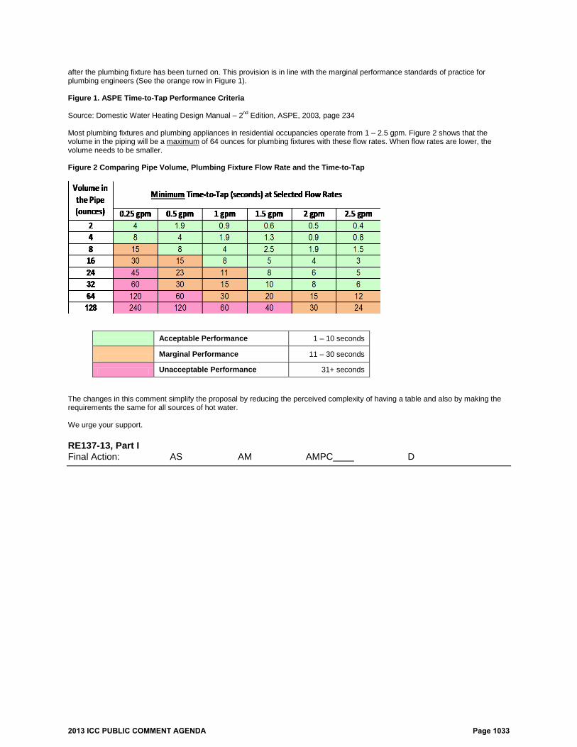
after the plumbing fixture has been turned on. This provision is in line with the marginal performance standards of practice for plumbing engineers (See the orange row in Figure 1). Figure 1. ASPE Time-to-Tap Performance Criteria Source: Domestic Water Heating Design Manual – 2nd Edition, ASPE, 2003, page 234 Most plumbing fixtures and plumbing appliances in residential occupancies operate from 1 – 2.5 gpm. Figure 2 shows that the volume in the piping will be a maximum of 64 ounces for plumbing fixtures with these flow rates. When flow rates are lower, the volume needs to be smaller. Figure 2 Comparing Pipe Volume, Plumbing Fixture Flow Rate and the Time-to-Tap
Acceptable Performance 1 – 10 seconds
Marginal Performance 11 – 30 seconds
Unacceptable Performance 31+ seconds The changes in this comment simplify the proposal by reducing the perceived complexity of having a table and also by making the requirements the same for all sources of hot water. We urge your support. RE137-13, Part I Final Action: AS AM AMPC D
2013 ICC PUBLIC COMMENT AGENDA Page 1033

RE137-13, Part II R202 (IRC N1101.9), R403.4.2 (NEW) (IRC N1103.4.2 (NEW)), R403.4.2.1 (NEW) (IRC N1103.4.2.1 (NEW)), Table R403.4.2.1 (NEW) (IRC Table N1103.4.2.1 (NEW)), R403.4.2.2 (NEW) (IRC N1103.4.2.2 (NEW)), R403.4.2.2.1 (NEW) (IRC N1103.4.2.2.1 (NEW)), IRC P2905 (NEW), IRC P2905.1 (NEW)
Proposed Change as Submitted THIS IS A 2 PART CODE CHANGE PROPOSAL. PART I WILL BE HEARD BY THE IECC-RESIDENTIAL ENERGY CONSERVATION CODE DEVELOPMENT COMMITTEE. PART II WILL BE HEARD BY THE IRC-PM COMMITTEE. SEE THE TENTATIVE HEARING ORDERS FOR THESE COMMITTEES. Proponent: Gary Klein, Affiliated International Management, LLC, representing self, ([email protected]) PART II IRC-P Add new text as follows:
SECTION P2905 HEATED WATER DISTRIBUTION SYSTEMS
P2905.1 Heated water supply piping. Heated water supply piping shall be in accordance with Section N1103.4.2. Reason: This change speeds hot water to the user, saves energy and water, and potentially lowers construction costs. All these are accomplished by limiting the volume of water in the pipes.
We have all have turned on the hot water and waited for it to get hot. While we wait water runs down the drain, wasting clean water. While we wait, our time is wasted. When we are done there is still hot water in the pipes, water which cools thereby wasting as much energy as it took to heat the water in the pipes. Pipes with larger volumes take longer to fill, waste more and are potentially more expensive to build.
This proposal remedies the problems above by reducing the water volume between the source of heated water and the use. The first method (Section R403.4.2.1) requires no calculation; it limits the water volume in the pipes by limiting the pipe length. The second option (Section R403.4.2.1) requires a calculation of volume in the pipes, but provides a table that translates the pipe length into a volume (columns 1 and 2); and provides quick options for different pipe assumptions in columns 3 and 4.
In simple form, cutting the volume in half: cuts the wait time in half, cuts the clean water wasted down the drain in half, cuts the energy loss while water goes through the pipes in half, and cuts the loss of energy from hot water left in the pipes after use in half.
A 2010 study done by the National Association of Home Builders Research Center shows the big impact of reducing hot water pipe volume. Figure 1, from that study, is below. The left half is for pipe 60 feet long. The right half is for pipe 30 feet long. Pick any case on the left and compare it to the same case on the right. Note there is always about a 50% reduction in piping energy lost in the 30-foot case. An example from the figure below, the energy loss of an uninsulated metal pipe 60 feet long drops from just over 10,000 kBtu to just over 5,000 kBtu for a pipe 30 feet long. Similarly uninsulated plastic pipe drops from about 7,300 kBtu to about 3,700 kBtu. The same pattern of reduction occurs when the piping is insulated.
Figure 1 Pipe Loss Comparison Using Parametric Analysis
2013 ICC PUBLIC COMMENT AGENDA Page 1034

Source: Domestic Hot Water System Piping Insulation: Analysis of Benefits and Costs, Figure 4, page 10 of 24, NAHB Research Center, December 2010. Why is the maximum volume 0.5 gallon when the source of heated water is a water heater? So that following standard practice for plumbing engineers and meeting the minimum requirements in the energy code will be aligned. At present, they are not, with the result that hot water delivery times are greater than 30 seconds after the tap is opened; unacceptable performance according to the American Society of Plumbing Engineers.
Why is the maximum volume 0.19 gallon when the source of heated water is a circulation loop or heat-traced pipe? In exchange for the flexibility in the location of the water heater relative to the plumbing fixtures and plumbing appliances, the allowable volume that will be wasted has been reduced and the time-to-tap improved so that it will almost always fall into ASPE’s range for Acceptable Performance.
The definition proposed is used in both the IRC and the IPC. For more information and background on issues related to hot water distribution and for a more detailed analysis in support of this proposal please go to http://www.aim4sustainability.com Follow the link on the home page to Codes. Cost impact: There are several ways to meet the requirements of this proposal, many of which cost less than current piping practices. I would recommend that builders and developers select one of the less expensive methods.
R403.4.2 #2 (NEW)-EC-KLEIN
Committee Action Hearing Results PART II – IRC – Plumbing Committee Action: Disapproved Committee Reason: There is no need to have a pointer in the plumbing chapters to direct the reader to another chapter of the IRC. There could be no end to the amount of pointers we could put into the IRC. Assembly Action: None
Individual Consideration Agenda
This item is on the agenda for individual consideration because a public comment was submitted. Public Comment: Gary Klein, Affiliated International Management, LLC, representing self, requests Approval as Submitted.
2013 ICC PUBLIC COMMENT AGENDA Page 1035

Commenter’s Reason: The Committee disapproved the code change because they felt there was no need of a pointer to another section in the IRC.
I am asking you to approve the proposal as originally submitted because I am concerned that if this doesn’t pass, are the plumbers, builders and code officials in your jurisdiction going to realize that something in the energy code section of the IRC is going to affect their work? I urge your support of this comment. RE137-13, Part II Final Action: AS AM AMPC D
2013 ICC PUBLIC COMMENT AGENDA Page 1036

RE138-13, Part I R202 (IRC N1101.9), R403.4.2 (New) (IRC N1103.4.2 (New)), R403.4.2.1 (New) (IRC N1103.4.2.1 (New)), Table R403.4.2.1 (New) (IRC N1103.4.2.1 (New)), R403.4.2.2 (New) (IRC N1103.4.2.2 (New)), R403.4.2.2.1 (New) (IRC N1103.4.2.2.1 (New)), IRC P2905 (New), IRC P2905.1 (New)
Proposed Change as Submitted THIS IS A 2 PART CODE CHANGE. PART I WILL BE HEARD BY THE IECC RESIDENTIAL ENERGY CONSERVATION CODE DEVELOPMENT COMMITTEE. PART II WILL BE HEARD BY THE IRC-PM COMMITTEE. SEE THE TENTATIVE HEARING ORDERS FOR THESE COMMITTEES. Proponent: Gary Klein, Affiliated International Management, LLC, representing self, ([email protected]) PART I – IECC RESIDENTIAL PROVISIONS Add new text as follows:
R403.4.2 (N1103.4.2) Efficient heated water supply piping. Heated water supply piping shall be in accordance with Section R403.4.2.1 or Section R403.4.2.2. The flow rate through ¼ inch piping shall not exceed 0.5 gpm (1.9 Lpm). The flow rate through 5/16 inch piping shall not exceed 1 gpm (3.8 Lpm). The flow rate through 3/8 inch piping shall not exceed 1.5 gpm (5.7 Lpm). R403.4.2.1 (N1103.4.2.1) Maximum allowable pipe length method. The maximum piping length from the nearest source of heated water to the termination of the fixture supply pipe for a public lavatory faucet shall be in accordance with the maximum piping length columns in Table R403.4.2. Where the piping contains more than one size of pipe, the largest size of pipe within the piping shall be used for determining the maximum allowable length of the piping in Table R403.4.2.1.
TABLE R403.4.2.1 (N1103.4.2.1)
PIPING VOLUME AND MAXIMUM PIPING LENGTHS
For SI: 1 inch=25.4 mm, 1 foot = 304.8 mm, 1 liquid ounce = 0.030 L
NOMINAL PIPE SIZE (inch)
VOLUME (liquid ounces
per foot length)
MAXIMUM PIPING LENGTH
(feet) LAVATORY FAUCETS—
PUBLIC 1/4 0.33 6 5/16 0.5 4 3/8 0.75 3 1/2 1.5 2 5/8 2 1 3/4 3 0.5 7/8 4 0.5 1 5 0.5
1 ¼ 8 0.5 1 ½ 11 0.5
2 or larger 18 0.5
2013 ICC PUBLIC COMMENT AGENDA Page 1037

R403.4.2.2 (N1103.4.2.2) Maximum allowable pipe volume method. The maximum piping volume from the nearest source of heated water to the termination of the fixture supply pipe for a public lavatory faucet shall be 2 ounces (0.06 L). The water volume in the piping shall be calculated in accordance with Section R404.4.2.2.1. R403.4.2.2.1 (N1103.4.2.2.1) Water volume determination. The volume shall be the sum of the internal volumes of pipe, fittings, valves, meters and manifolds between the nearest source of heated water and the termination of the fixture supply pipe. The volume in the piping shall be determined from the volume column in Table R403.4.2.1. The volume contained within fixture shut off valves, within flexible water supply connectors to a fixture fitting and within a fixture fitting shall not be included in the water volume determination. Where heated water is supplied by a recirculating system or heat-traced piping, the volume shall include the portion of the fitting on the branch pipe that supplies water to the fixture. Reason: The problem of heated water taking an excessively long time to arrive at lavatory faucets in public restrooms is well known. The length of time the faucets are used during each hand washing event is very short, often around 5 seconds. Federal law requires low flow rate or small, metered volumes for the faucets in these applications. Health codes expect heated water for washing hands in these applications. The dilemma is that the volume of not-hot water in the piping from the source of hot water to the faucets is much too large for the heated water to arrive in a timely fashion; even at the 50-foot limit currently required in the 2012 IPC. Supporting this proposal will correlate the IECC with Federal law and local health codes by providing heated water for hand washing in a timely matter.
The delivery of hot water to public lavatory faucets needs to be considered separately because of potential health issues. The events are short and the flow rates are low. Table 1 shows the time-to-tap performance based on the requirements in the proposal. The 0.25 and 0.5 gpm columns are typical of the flow rates for public lavatory faucets. The volume in the pipe was chosen so that heated water would arrive in the first part of the hot water event so that every person who uses the public lavatory will have the benefits of hot water.
Table 1 Time-to-Tap Performance when the Volume in the Piping from the Source to the Use is 2 ounces
Volume in the Pipe (ounces)
Minimum Time-to-Tap (seconds) at Selected Flow Rates
0.25 gpm 0.5 gpm 1 gpm 1.5 gpm 2 gpm 2.5 gpm
2 3.8 1.9 0.9 0.6 0.5 0.4
The energy savings comes from not losing the heat from the water as it tries to arrive at the faucets. For more information and background on issues related to hot water distribution please read the 4-part series at: http://www.allianceforwaterefficiency.org/Residential_Hot_Water_Distribution_System_Introduction.aspx Cost impact: There are several ways to meet the requirements of this proposal, some of which cost less than current heated water system practices. I would recommend that builders and developers select one of the less expensive methods.
R403.4.2 #3 (New)-EC-KLEIN
Committee Action Hearing Results PART I – IECC – Residential Committee Action: Disapproved Committee Reason: This is a similar proposal to RE137. Point of use water heaters could be used to solve the problem that this proposal is trying to solve. Assembly Action: Approved as Submitted
2013 ICC PUBLIC COMMENT AGENDA Page 1038
Individual Consideration Agenda This code change proposal is on the agenda for individual consideration because the proposal received a successful assembly action of Approved as Submitted and public comments were received. Public Comment 1: Gary Klein, Affiliated International Management, LLC, representing self,requests Approval as Submitted. Commenter’s Reason: The Committee disapproved this proposal saying that point of use water heaters could be used to solve the problem that this proposal is trying to solve.
The committee was correct. Point-of-use water heaters are one of the possible solutions to the problem we have all encountered: not getting hot or tempered water to wash our hands in public restrooms. This proposal requires that, regardless of the method used to heat the water – including point-of-use water heaters – the volume between the source of hot water and the public lavatory faucets must be small. This is to ensure that heated water is actually delivered to the faucets for every user.
We urge your support of the Assembly Action and approve this code change. Public Comment 2: Ryan Meres, Institute for Market Transformation, representing self, requests Approval as Modified by this Public Comment. Modify the proposal as follows: R403.4.2 (IRC N1103.4.2) Efficient heated water supply piping. From the nearest source of heated water to a public lavatory faucet, the time for heated water to arrive at its destination shall not exceed 5 seconds when the faucet is turned on to full hot or for hands-free faucets, with the mixing valve set to the specified outlet temperature. Water heaters, circulating water systems and heat trace temperature maintenance systems shall be considered sources of heated water. Heated water supply piping shall be in accordance with Section R403.4.2.1 or Section R403.4.2.2. The flow rate through ¼ inch piping shall not exceed 0.5 gpm (1.9 Lpm). The flow rate through 5/16 inch piping shall not exceed 1 gpm (3.8 Lpm). The flow rate through 3/8 inch piping shall not exceed 1.5 gpm (5.7 Lpm). R403.4.2.1 (IRC N1103.4.2.1) Maximum allowable pipe length method. The maximum allowable piping length from the source of hot or tempered water to the termination of the fixture supply pipe shall be in accordance with the maximum piping length columns in Table R403.4.2. Where the piping contains more than one size of pipe, the largest size of pipe within the piping shall be used for determining the maximum allowable length of the piping in Table R403.4.2. R403.4.2.2 (IRC N1103.4.2.2) Maximum allowable pipe volume method. The water volume in the piping shall be calculated in accordance with Section R404.4.2.2.1. The maximum volume of water in the piping from the source of heated water to public lavatory faucets, metering or non-metering, shall be 2 ounces (0.06 L). R403.4.2.2.1 (IRC N1103.4.2.2.1) Water volume determination. The volume shall be the sum of the internal volumes of pipe, fittings, valves, meters and manifolds between the source of heated water and the termination of the fixture supply pipe. The volume in the piping shall be determined from the volume column in Table R403.4.2. The volume contained within fixture shut off valves, within flexible water supply connectors to a fixture fitting and within a fixture fitting shall not be included in the water volume determination. Where heated water is supplied by a recirculating system or heat-traced piping, the volume shall include the portion of the fitting on the branch pipe that supplies water to the fixture.
TABLE R403.4.2 ((IRC TABLE N1103.4.2) PIPING VOLUME AND MAXIMUM PIPING LENGTHS
Add new definition: WATER HEATER. Any heating appliance or equipment that heats potable water and supplies such water to the potable hot water distribution system. Commenter’s Reason: The Committee disapproved this proposal saying that point of use water heaters could be used to solve the problem that this proposal is trying to solve.
This proposal focuses on the delivery of heated water to public lavatory faucets a problem all of us are familiar with. The committee was correct. Point-of-use water heaters are one of the possible solutions to the problem we have all encountered: not getting hot or tempered water to wash our hands in public restrooms.
2013 ICC PUBLIC COMMENT AGENDA Page 1039

Current plumbing practice results in a significant waste of energy, without actually providing the intended or code required (health) service. The energy waste occurs when the water in the branches and fixture supplies cools down between the intermittent uses that occur in public bathrooms. The solution is to limit the volume between the source of heated water and the faucets or the time-to-tap for hot water to arrive after the faucet is turned on.
The purpose of this proposal is to provide better, more energy efficient, hot water service to the occupants of our buildings. Installing the hot water piping so that the delivery is more efficient will stay with the building for 50-100 years. Similarly the pain of an inefficient system will last just as long.
This comment simplifies the original proposal by saying that the hot water supply piping shall deliver hot water within 5 seconds after the public lavatory faucet has been turned on. This time limit is important because the actual amount of time a public lavatory faucet is used is generally less than 10 seconds. It only makes sense to have a code that delivers hot water in the first portion of the short event. This revised code section is now in line with the acceptable performance standards of practice for plumbing engineers (See the green row in Figure 1). Figure 1. ASPE Time-to-Tap Performance Criteria Source: Domestic Water Heating Design Manual – 2nd Edition, ASPE, 2003, page 234 Public lavatory faucets are a special case in the code as their flow rate is generally 0.5 gpm or less. However, since most public lavatory faucets are hands-free, the hot water portion of the mix is closer to 0.25 gpm. Figure 2 shows that the volume in the piping needs to be small for the heated water to arrive quickly at the faucets. Figure 2 Comparing Pipe Volume, Plumbing Fixture Flow Rate and the Time-to-Tap
The changes in this comment simplify the proposal by reducing the complexity of having a table. We urge your support. RE138-13, Part I Final Action: AS AM AMPC D
Acceptable Performance 1 – 10 seconds
Marginal Performance 11 – 30 seconds
Unacceptable Performance 31+ seconds
2013 ICC PUBLIC COMMENT AGENDA Page 1040

RE138-13, Part II R202 (IRC N1101.9), R403.4.2 (NEW) (IRC N1103.4.2 (NEW)), R403.4.2.1 (NEW) (IRC N1103.4.2.1 (NEW)), Table R403.4.2.1 (NEW) (IRC N1103.4.2.1 (NEW)), R403.4.2.2 (NEW) (IRC N1103.4.2.2 (NEW)), R403.4.2.2.1 (NEW) (IRC N1103.4.2.2.1 (NEW)), IRC P2905 (NEW), IRC P2905.1 (NEW)
Proposed Change as Submitted THIS IS A 2 PART CODE CHANGE. PART I WILL BE HEARD BY THE IECC RESIDENTIAL ENERGY CONSERVATION CODE DEVELOPMENT COMMITTEE. PART II WILL BE HEARD BY THE IRC-PM COMMITTEE. SEE THE TENTATIVE HEARING ORDERS FOR THESE COMMITTEES. Proponent: Gary Klein, Affiliated International Management, LLC, representing self, ([email protected]) PART II-IRC-P Add new text as follows:
SECTION P2905 HEATED WATER DISTRIBUTION SYSTEMS
P2905.1 Heated water supply piping. Heated water supply piping shall be in accordance with Section N1103.4.2. Reason: The problem of heated water taking an excessively long time to arrive at lavatory faucets in public restrooms is well known. The length of time the faucets are used during each hand washing event is very short, often around 5 seconds. Federal law requires low flow rate or small, metered volumes for the faucets in these applications. Health codes expect heated water for washing hands in these applications. The dilemma is that the volume of not-hot water in the piping from the source of hot water to the faucets is much too large for the heated water to arrive in a timely fashion; even at the 50-foot limit currently required in the 2012 IPC. Supporting this proposal will correlate the IECC with Federal law and local health codes by providing heated water for hand washing in a timely matter.
The delivery of hot water to public lavatory faucets needs to be considered separately because of potential health issues. The events are short and the flow rates are low. Table 1 shows the time-to-tap performance based on the requirements in the proposal. The 0.25 and 0.5 gpm columns are typical of the flow rates for public lavatory faucets. The volume in the pipe was chosen so that heated water would arrive in the first part of the hot water event so that every person who uses the public lavatory will have the benefits of hot water.
Table 1 Time-to-Tap Performance when the Volume in the Piping from the Source to the Use is 2 ounces
Volume in the Pipe (ounces)
Minimum Time-to-Tap (seconds) at Selected Flow Rates
0.25 gpm 0.5 gpm 1 gpm 1.5 gpm 2
gpm 2.5 gpm
2 3.8 1.9 0.9 0.6 0.5 0.4 The energy savings comes from not losing the heat from the water as it tries to arrive at the faucets. For more information and background on issues related to hot water distribution please read the 4-part series at: http://www.allianceforwaterefficiency.org/Residential_Hot_Water_Distribution_System_Introduction.aspx Cost impact: There are several ways to meet the requirements of this proposal, some of which cost less than current heated water system practices. I would recommend that builders and developers select one of the less expensive methods. R403.4.2 #3 (NEW)-EC-KLEIN
Committee Action Hearing Results PART II – IRC – Plumbing
2013 ICC PUBLIC COMMENT AGENDA Page 1041

Committee Action: Disapproved Committee Reason: There is no need to have a pointer in the plumbing chapters to direct the reader to another chapter of the IRC. There could be no end to the amount of pointers we could put into the IRC. Assembly Action: None
Individual Consideration Agenda
This item is on the agenda for individual consideration because a public comment was submitted. Public Comment: Gary Klein, Affiliated International Management, LLC, representing self, requests Approval as Submitted. Commenter’s Reason: The Committee disapproved the code change because they felt there was no need of a pointer to another section in the IRC.
I am asking you to approve the proposal as originally submitted because I am concerned that if this doesn’t pass, are the plumbers, builders and code officials in your jurisdiction going to realize that something in the energy code section of the IRC is going to affect their work?
I urge your support of this comment. RE138-13, Part II Final Action: AS AM AMPC D
2013 ICC PUBLIC COMMENT AGENDA Page 1042

RE143-13 R403.6 (IRC N1103.6)
Proposed Change as Submitted Proponent: Philip Debes, Dan Deen, Steve Frazer, Lloyd Larkin, Allan Tyson, Jim Walker, all of P and N Distribution, Inc. representing themselves. Clifton Payne of DNV KEMA (Det Norske Veritas and Keuring Elektrotechnische Materialen Arnhem) Energy and Sustainability, representing Energy Design Systems, Philip Jeffers, Energy Design Systems, Inc, representing self, Scott Miller, Knauf Insulation representing self Revise as follows: R403.6 (N1103.6) Equipment Sizing (Mandatory). Heating and cooling equipment shall be sized in accordance with ACCA Manual S based on building loads calculated in accordance with ACCA Manual J or other approved heating and cooling calculation methodologies. standard engineering heat loss and heat gain formulas coupled with appropriate weather data, home construction materials and other considerations normally used in the HVAC industry. Reasons: [DEBES, DEEN, FRAZER, LARKIN, TYSON, WALKER] ACCA Manual J and ACCA Manual S are trademarks. Code officials mistakenly believe ACCA is the certifying agent for IECC code compliance. ACCA charges royalties for ACCA approved software and resells software directly to contractors. ACCA is an HVAC software competitor, not a certifying authority. [PAYNE] ACCA Manual J and ACCA Manual S are trademarks. ACCA is not the certifying agent for IECC code compliance, as ACCA Code officials appear to mistakenly believe. ACCA charges royalties for ACCA approved software and resells software directly to contractors. ACCA is an HVAC software competitor, not a certifying authority. By referencing ACCA in R403.6, the IECC would be selecting and endorsing one product from the marketplace over overs, not simply providing a standard that should be used to size HVAC equipment. This would create an unlevel playing field by providing ACCA with a competitive advantage. [JEFFERS] 1. ACCA Manual J and ACCA Manual S are trademarks. ACCA and ACCA’s software partners are using the IECC code to intimidate contractors. See attachment 1: ACCA “Contractors Beware”, See attachment 2: Bob Volin, ACCA Code Committee Member, Photo Shopping his Letterhead onto the Code’s Section R403.6 and convincing contractors into buying “ACCA Approved Software” and trying to force software developers into royalty payments totaling millions of dollars. ACCA is restraining trade, eliminating competition, and inhibiting development of more accurate software and procedures. Building Inspectors mistakenly interpret “in accordance with” to mean “approved by”. ACCA uses this fact to create a de-facto IECC software certification process, making millions in fees, royalties, and reselling the software ACCA “approves”. ACCA is a software competitor and Section R403.6 creates unfair competition. 2. For existing houses ACCA’s Manual J procedure has no relationship to any sound engineering practice. None of the inputs such as a home’s leakage rate, duct loss/gain, or any other value are known, and these inputs can have wide tolerances. Contractors use inputs that give them the answers they want. This is called confirmation Bias. An ACCA load calculation on an existing house is no different from guessing the size. The fact that contractors work ACCA’s procedure backwards is widely known in the HVAC industry. ACCA load calculations average 140% of operating loads and can contribute to comfort, health, safety issues, and dramatically overstate energy usage.
“they simply change some of the inputs to make the procedure spit out answer they're comfortable with and no one questions their answers." - Hank Rutkowski P.E. Author ACCA Manual J.
3. There is no evidence what so ever that “proper sizing” saves energy. ATTACHMENT #1 From: Melissa Broadus, ACCA [mailto:[email protected]] Sent: Tuesday, September 06, 2011 2:40 PM
To: [email protected] Subject: ACCA NEWS: Contractors: Beware of Inappropriate Load Calculation Software
For Immediate Release
2013 ICC PUBLIC COMMENT AGENDA Page 1043

September 6, 2011 Media Contact: Melissa Broadus, [email protected]
Contractors: Beware of Inappropriate Load Calculation Software
Manual J ® is the ANSI-approved national standard for determining residential load calculations for HVACR systems, and is required by many building codes and regulations. It is produced by the Air Conditioning Contractors of America (ACCA), the nation's largest association of indoor environmental systems professionals.
Given the complexities of modern construction, contractors and design professionals are encouraged to use software for accurate system design. However, not all load calculation software is created equal.
ACCA is reminding contractors that only those software programs that have been approved and licensed by ACCA as “Powered by Manual J ®” can be considered in compliance with codes and regulations requiring the use of Manual J ®.
As of today, the only software programs that meet the requirements for Manual J ® load calculations are:
• RHVAC Residential Load Calculation from Elite Software
• Right – J from Wrightsoft
• AccuLoads from ADTEK Software Company
• Florida Solar Energy Center‘s EnergyGauge
Any other software program, online service or mobile application cannot be considered to be compliant with the Manual J ® standard and should not be used where Manual J ® is required. Use of non-authorized software may pose a liability for the contractor that installs the system.
For more information on Manual J ®, the ACCA system design process, and load calculation software, visit https://www.acca.org/industry/system-design.
Software providers interested in applying for validation and licensing of their product should contact Glenn Hourahan at [email protected].
Manual J ® is a registered federal trademark of the Air Conditioning Contractors of America.
The Air Conditioning Contractors of America (ACCA) is a non-profit association serving more than 60,000 professionals and 4,000 businesses in the HVACR community, who work together to promote professional contracting, energy efficiency, and healthy, comfortable indoor environments for all Americans. For more information, visit www.acca.org.
You are receiving this email because you are a member of ACCA and asked to receive communications by email, or you subscribed through our website. To manage your email preferences or to unsubscribe, go to options.To change your email address,
please reply to this email with your new address in the body.
Air Conditioning Contractors of America 2800 Shirlington Road, Suite 300 | Arlington, VA 22206 | 703-575-4477 | www.acca.org
2013 ICC PUBLIC COMMENT AGENDA Page 1044

ATTACHMENT #2
[MILLER] ACCA Manual J and ACCA Manual S are trademarks. Code officials mistakenly believe ACCA is the certifying agent for IECC code compliance. ACCA charges royalties for ACCA approved software and resells software directly to contractors. ACCA is an HVAC software competitor, not a certifying authority.
ACCA Manual S and Manual J are trademarks of ACCA. According to ACCA, all software must be approved by ACCA or it does not comply with the intent of the IECC R-code and there are significant fees associated with the ACCA approval process. From the following link demonstrates that ACCA believes it has authority to appraise and charge a fee to other software developers for all software used in the IECC 2012 load calculation process:
2013 ICC PUBLIC COMMENT AGENDA Page 1045

https://www.acca.org/archives/news-and-media/news-room/press-releases/5524 The contents of the above link are as follows and the highlighted portion should be considered problematic from a trade restriction standpoint. It can be proven that this position has cost manufacturers significant sales because the manufacturer’s software (while correct) has not been approved by and fees paid to ACCA.
Contractors: Beware of Inappropriate Load Calculation Software
For Immediate Release: September 6, 2011 Contact: [email protected] 703-824-8842 Manual J ® is the ANSI-approved national standard for determining residential load calculations for HVACR systems, and is required by many building codes and regulations. It is produced by the Air Conditioning Contractors of America (ACCA), the nation’s largest association of indoor environmental systems professionals. Given the complexities of modern construction, contractors and design professionals are encouraged to use software for accurate system design. However, not all load calculation software is created equal. ACCA is reminding contractors that only those software programs that have been approved and licensed by ACCA as “Powered by Manual J ®” can be considered in compliance with codes and regulations requiring the use of Manual J ®. As of today, the only software programs that meet the requirements for Manual J ® load calculations are:
• RHVAC Residential Load Calculation from Elite Software • Right – J from Wrightsoft • AccuLoads from ADTEK Software Company • Florida Solar Energy Center‘s EnergyGauge
Any other software program, online service or mobile application cannot be considered to be compliant with the Manual J ® standard and should not be used where Manual J ® is required. Use of non-authorized software may pose a liability for the contractor that installs the system. For more information on Manual J ®, the ACCA system design process, and load calculation software, visit https://www.acca.org/industry/system-design.
Cost Impact: The code change proposal will not increase the cost of construction.
R403.6-EC-DEBES.DOC
Committee Action Hearing Results Committee Action: Disapproved Committee Reason: The committee believes that the ACCA Standards continue to be accepted and useful references for equipment sizing. The references do not preclude the code user from using other software. Assembly Action: None
Individual Consideration Agenda
This item is on the agenda for individual consideration because a public comment was submitted. Public Comment: Richard Grace, Fairfax County, representing Virginia Plumbing and Mechanical Inspectors Association and Virginia Building and Code Officials Association requests Approval as Modified by this Public Comment. Modify the proposal as follows:
2013 ICC PUBLIC COMMENT AGENDA Page 1046

R403.6 (N1103.6) Equipment Sizing (Mandatory). Heating and cooling equipment shall be sized in accordance with ACCA Manual S or other approved sizing methodologies based on building loads calculated in accordance with ACCA Manual J or other approved heating and cooling calculation methodologies. standard engineering heat loss and heat gain formulas coupled with appropriate weather data, home construction materials and other considerations normally used in the HVAC industry. Commenter’s Reason: The current language permits ONLY the use of ACCA Manual S to size residential heating and cooling equipment. There are other sizing methodologies, such as ASHRAE’s Handbook series, that are quite acceptable and approvable for use in sizing residential HVAC equipment. RE143-13 Final Action: AS AM AMPC D
2013 ICC PUBLIC COMMENT AGENDA Page 1047

RE144-13 R403.6 (IRC N1103.6)
Proposed Change as Submitted
Proponent: Richard Grace, Virginia Plumbing and Mechanical Inspectors Association and Virginia Building and Code Officials Association ([email protected]) Revise as follows: R403.6 (N1103.6) Equipment and appliance Sizing (Mandatory). Heating and cooling equipment and appliances shall be sized in accordance with ACCA Manual S based on building loads calculated in accordance with ACCA Manual J or other approved heating and cooling calculation methodologies.
Exception: Heating and cooling equipment and appliances shall not be limited to the capacities determined in accordance with Manual S where any of the following conditions apply:
1. The specified equipment or appliance utilizes multi-stage technology or variable refrigerant flow technology and the loads calculated in accordance with Manual J fall within the range of the manufacturer’s published capacities for that equipment or appliance.
2. The specified equipment or appliance manufacturer’s published capacities cannot satisfy both the total and sensible heat gains calculated in accordance with Manual J and the manufacturer’s next larger standard size unit is specified.
3. The specified equipment or appliance is the smallest capacity unit available from the specified manufacturer.
Reason: Item 1 - Current technology is widely available that incorporates multi-stage or VRF systems for increased efficiency. Some of these appliances have such a wide span of functionality that they extend beyond the allowable requirements outlined in Manual S. However, this technology allows the appliance to operate between minimum and maximum capacities, based on loads imposed, thus eliminating the problems associated with single-stage, oversized appliances. Additionally, the appliance will operate efficiently during times where outdoor air temperatures exceed those used to calculate the loads in Manual J.
Item 2 - Often times, the appliance manufacturer’s published total and sensible capacities are at odds with the requirements of Manual S. There are many cases where the total capacity of the appliance will fall within the parameters of Manual S in relation to the calculated total gain, however the sensible capacity of the appliance may fall short of the calculated sensible gain, thus unable to provide efficient sensible cooling for the space. When the manufacturer’s next standard size larger is chosen to meet the sensible gain, the total capacity of the appliance may then exceed the requirements of Manual S. Choosing the larger appliance will enable a more efficient and effective system.
Item 3 - The current code language does not have provisions for sizing appliances for minimal dwelling unit or dwelling addition loads, other than forcing owners and contractors to change appliances to less desirable systems. For example; a 2 story townhouse, in climate zone 4, with 600 square feet per floor wants to utilize a two-zone system, or a separate heat pump system for each floor. A 1.5 ton unit per floor would exceed the requirements of Manual S, however a 1.5 ton unit could be the smallest available appliance made by the desired manufacturer. Current language would require a complete design change, such as utilizing a single appliance to serve the entire dwelling rather than the more desirable two-zone system, or requiring a system that utilizes electric baseboard heating and window-mounted air conditioning units. This is absurd, and an unfair to an owner that desires to reduce energy costs. Cost Impact: None
R403.6-EC-GRACE.DOC
Committee Action Hearing Results Committee Action: Disapproved Committee Reason: The proponent requested disapproval. The proponent intends to submit public comments to ACCA Manual S, rather than pursue code change in the IECC. The request for disapproval would allow the proponent to pursue this later in the public comment phase if need be. Assembly Action: None
2013 ICC PUBLIC COMMENT AGENDA Page 1048

Individual Consideration Agenda This item is on the agenda for individual consideration because public comments were submitted. Public Comment 1: Richard Grace, Fairfax County, representing Virginia Plumbing and Mechanical Inspectors Association and Virginia Building and Code Officials Association requests Approval as Modified by this Public Comment. Modify the proposal as follows: R403.6 (N1103.6) Equipment and appliance Sizing (Mandatory). Heating and cooling equipment and appliances shall be sized in accordance with ACCA Manual S or other approved sizing methodologies based on building loads calculated in accordance with ACCA Manual J or other approved heating and cooling calculation methodologies.
Exception: Heating and cooling equipment and appliances sizing shall not be limited to the capacities determined in accordance with Manual S or other approved sizing methodologies where any of the following conditions apply:
1. The specified equipment or appliance utilizes multi-stage technology or variable refrigerant flow technology and the loads calculated in accordance with Manual J the approved heating and cooling methodology fall within the range of the manufacturer’s published capacities for that equipment or appliance.
2. The specified equipment or appliance manufacturer’s published capacities cannot satisfy both the total and sensible heat gains calculated in accordance with Manual J the approved heating and cooling methodology and the manufacturer’s next larger standard size unit is specified.
3. The specified equipment or appliance is the lowest capacity unit available from the specified manufacturer. Commenter’s Reason: After listening to the discussions presented during the Committee Action Hearings, we have incorporated those concerns within this modification. The first being the addition of “other approved sizing methodologies”. ACCA’s Manual S is not the only approved, appropriate sizing methodology available to size residential HVAC equipment. The current language would not permit other sizing methodologies such as ASHRAE’s Handbook series. The second modification was to reword the language to provide clarity to the text. The third modification was to remove the third exception based on concerns voiced during testimony about the broad aspects that such an exception would permit. The following is from the original reason statement: Item 1 - Current technology is widely available that incorporates multi-stage or VRF systems for increased efficiency. Some of these appliances have such a wide span of functionality that they extend beyond the allowable requirements outlined in Manual S. However, this technology allows the appliance to operate between minimum and maximum capacities, based on loads imposed, thus eliminating the problems associated with single-stage, oversized appliances. Additionally, the appliance will operate efficiently during times where outdoor air temperatures exceed those used to calculate the loads in Manual J. Item 2 - Often times, the appliance manufacturer’s published total and sensible capacities are at odds with the requirements of Manual S. There are many cases where the total capacity of the appliance will fall within the parameters of Manual S in relation to the calculated total gain, however the sensible capacity of the appliance may fall short of the calculated sensible gain, thus unable to provide efficient sensible cooling for the space. When the manufacturer’s next standard size larger is chosen to meet the sensible gain, the total capacity of the appliance may then exceed the requirements of Manual S. Choosing the larger appliance will enable a more efficient and effective system. Public Comment 2: Luis Romeo Escobar, Air Conditioning Contractors of America requests Disapproval. Commenter’s Reason: The proposed exceptions to ACCA Manual S should be disapproved for the following reasons:
1. Variable refrigerant flow (VRF) technology is addressed in the revised Manual S. The committee that led the revision effort included representatives of VRF manufacturers. The new Manual S over size limits have been vetted by these committee members and is based on the available OEM expanded performance data. ACCA is following ICC procedures to ensure that the updated Manual S is the one referenced in the 2015 IRC and IECC.
2. Exceptions #2 and #3 are not based on sound technical grounds, but instead are contrived to benefit sales of a particular product class. This is specifically against the entire intent of Manual S and exactly what the industry needs to get away from.
3. The cost impact of this proposed change is not “none” as indicated by the proponents. Larger-than-necessary equipment will generally have higher initial costs (longer pay-back), higher energy costs due to constant cycling on-and-off of the equipment, shortened equipment lifespan (again, due to the wear-and-tear of constant cycling), and will have higher
2013 ICC PUBLIC COMMENT AGENDA Page 1049

maintenance costs if the proponents’ example of two oversized units for one house is the case (homeowners are generally charged based on the number of units being serviced).
4. In the reasoning for item 3 the proponents state that a homeowner will see reduced energy costs by installing two oversized units as opposed to one properly sized unit – this patently absurd and unsubstantiated. The proponents, unfortunately not unlike many design practitioners, seem to think that installing two units is the only way to properly zone a home, which is not the case.
5. The main reason why the industry has a standard to avoid oversizing is in order to ensure that there is proper humidity control in the home. Severely oversized equipment does not stay on long enough for the coil to reach a low enough temperature for adequate moisture removal. This can result in the presence of mold and mildew, not to mention lead to an uncomfortable interior ambience (the dry-bulb temperature will be low, but the humidity high so it will feel clammy to the occupant). Clearly, this proposal would in no way makes a home safer, but instead puts the occupants in greater risk of developing serious health issues from the presence of moisture.
6. Manual S is not a suggestion, as the proponents erroneously purport. It is an industry developed, ANSI recognized standard that sets clear oversize limits that must be adhered to. While the old Manual S did have permissive language that may not have been adequately addressed by the directions on the inside cover, great care has been taken to ensure that the normative sections of the new Manual S are written in mandatory, enforceable language that is acceptable for the i-codes. It will undergo a second ANSI public review, during which anyone (proponents included) may submit a comment to correct any deficiencies.
7. Any exceptions to Manual S should be based on industry research, and not on personal anecdote. To date, no credible research has been produced that supports the claim that hugely oversized HVAC equipment is desirable or leads to a safer, more sustainable, more affordable, or more resilient home.
8. For situations in which the OEM expanded performance data is not available, the new Manual S provides a path for compliance in which the manufacturer certifies that the equipment meets the home’s physical requirements.
9. Manual S already has procedures that allow for regional differences (the comparison of heating degree days to cooling degree days for qualification of different heat pump sizing limits).
10. One common problem that is used as justification for gross oversizing is that the specified OEM doesn’t offer equipment with small enough capacity for the load requirements. Unfortunately, this will continue to be that case as long as the Manual S requirements are not enforced. This proposal is effectively asks code officials to compensate for a lack of OEM product offerings, which is not the purpose of the building codes (in fact, it will serve as a catch 22 that will prolong the same problem).
RE144-13 Final Action: AS AM AMPC D
2013 ICC PUBLIC COMMENT AGENDA Page 1050

RE145-13 R403.9.3 (NEW) (IRC N1103.9.3.1 (NEW))
Proposed Change as Submitted Proponent: Edward R. Osann, Natural Resources Defense Council, on behalf of self ([email protected]) Add new text as follows: R403.9.3.1 (N1103.9.3.1) Mechanical retraction mechanism. Vapor retardant pool covers having a dry weight of 40 lbs (18.1 kg) or more for heated pools associated with one- or two-family homes shall be provided with a mechanical retraction mechanism. The mechanism shall be designed for the cover material, the cover weight and the dimensions of the cover. Reason: Pool covers serve to retain heat in heated pool systems and reduce water loss due to evaporation – but only when used. Swimming pools at single-family residences are frequently not professionally managed or maintained, and such pools are most likely to go for several consecutive days without use. These characteristics support the use and value of a pool cover. However, the frequent deployment and retraction of a large pool cover by an individual swimmer in a single-family setting is problematic, contributing to widespread disuse of this valuable energy- and water-saving feature.
This proposal would require a pool cover to come with a means for mechanical retraction if it weighs 40 pounds or more. While the most common type of floating cover material is relatively light (0.1 lb per ft2), the weight of a cover for a moderately sized back yard pool (18’ X 36’) can surpass 60 lbs. and be unwieldy for an individual to handle. The proposal is not specific as to the means or design of the device for mechanical retraction, and does not require a permanently affixed automatic retraction system. A hand operated device of suitable size would meet the requirements of this proposal. Cost Impact: Hand operated mechanical equipment for the retraction of pool covers are marketed at around $200, and are available from several manufacturers. At least 5 manufacturers provide automatic pool cover equipment. R403.9.3.1 (NEW)-EC-OSANN.DOC
Committee Action Hearing Results Committee Action: Disapproved Committee Reason: This proposed requirement is not an energy code issue. Assembly Action: None
Individual Consideration Agenda
This item is on the agenda for individual consideration because a public comment was submitted. Public Comment: Edward R. Osann, Natural Resources Defense Council representing self, requests Approval as Modified by this Public Comment. Modify the proposal as follows: R403.9.3.1 Mechanical retraction mechanism required. Vapor retardant pool covers having a dry weight of 40 lbs (18.1 kg) or more for heated in-ground pools associated with one- or two-family homes shall be provided with a mechanical retraction mechanism. The mechanism shall be designed for the cover material, the cover weight and the dimensions of the cover. Reason: The committee raised concern over the suitability and availability of retraction equipment for above-ground pools. In response, the modification in this comment would limit the requirement to covers provided for in-ground pools. RE145-13 Final Action: AS AM AMPC D
2013 ICC PUBLIC COMMENT AGENDA Page 1051

RE146-13 R403.10 (New) (IRC N1103.10 (New))
Proposed Change as Submitted Proponent: Steve Rosenstock, Edison Electric Institute, representing Edison Electric Institute ([email protected]( Add new text as follows: R403.10 (N1103.10) Fireplace systems (Mandatory). Fuel gas fired fireplace systems shall not have continuously burning pilot lights. Reason: This language is consistent with the language on continuously burning pilot lights for pool heaters and gas lighting systems in the IECC. As of April 2012, under a 2009 US Department of Energy rulemaking, residential gas cooking equipment is not allowed to have continuously burning pilot lights.
According to the Hearth, Patio, and Barbecue Association, between 573,000 and 1,017,000 gas fireplace / hearth systems were shipped to North America every year between 2008 and 2011 (about 67 to 70% of total hearth shipments. See http://www.hpba.org/index.php?id=238 for more details). Many of these units are shipped to new homes with continuously burning pilot lights, ranging from 800 to 1,200 Btu’s per hour. For a fireplace that has a pilot light using 1,000 Btu/hr, and is in “standby” mode for about 8000 hours per year (assuming that the fireplace is used 5 hours per day for 150 days of the year), the pilot light uses 8 million Btu’s, or 80 therms. At a national average cost of $1.06 per therm, the cost to a typical consumer is nearly $85 per year.
With propane systems, 8 million Btu’s is equivalent to 87.59 gallons. At a national average cost of $2.56 per gallon (Federal Register page 24940 April 26, 2012, Representative Average Unit Costs of Energy), the cost to a propane consumer is slightly more than $224 per year.
As a reference point, according to the 2010 AGA Gas Facts 2008, a typical gas range uses about 52 therms (5.1 Mcf) per year, and a typical clothes dryer uses about 50 therms (49 Mcf) per year (Table 10-1, page 78). In fact, according to the AGA publication, in the Pacific region of the US, residential natural gas fireplaces use more energy (28.3 Mcf) than a typical residential natural gas water heater (22.1 Mcf) and gas range (5.1 Mcf) combined.
Significant energy savings are available with current technology. With advanced controls (electronic spark ignition, for example), the standby energy losses are eliminated, and the average US consumer saves nearly $85 to $224 per year, based on the examples shown. Cost Impact: The code change proposal will not increase the cost of construction. Electronic ignitions are widely available.
R403.10-EC-ROSENSTOCK.DOC
Committee Action Hearing Results Committee Action: Approved as Submitted Committee Reason: Continuously burning pilot lights use a significant amount of energy. Disallowing them will represent energy savings. This action is consistent with previous year’s actions on gas pilot lights for pool heaters and gas lighting systems. Assembly Action: Disapproved
Individual Consideration Agenda
This code change proposal is on the agenda for individual consideration because the proposal received a successful assembly action of Disapproved and because public comments were submitted. Public Comment 1: Don Denton, representing Don Denton, Consulting Engineer requests Disapproval. Commenter’s Reason: Proposed code change RE146-13 should be disapproved, because unvented gas heating products would be eliminated by its adoption. It is improper for three key reasons:
2013 ICC PUBLIC COMMENT AGENDA Page 1052

First, a code change should not eliminate a safety requirement of an ANSI national product standard and the United States Consumer Product Safety Commission (CPSC). The ANSI national product standard requires unvented gas heating products to have a precisely made standing pilot as a safety device to shut-off the unit in case of oxygen reduction in the room air. It has been mandated by the CPSC for the past 34 years.
Second, no code change related to energy conservation should eliminate the most energy efficient gas appliance that exists. Besides, the standing pilot’s energy isn’t wasted, as it adds needed heat to the room.
Third, consumers should not be denied the choice to buy unvented gas heating products. The proponent’s claim that the code change would not increase the cost of construction is wrong. Unvented gas heating products provide not only energy savings, but acquisition and installation savings as well. Public Comment 2: Mark Krebs, Laclede Gas Co., representing self requests Disapproval. Commenter’s Reason: Fuel gas-fired fireplaces are short-term use decorative hearth products that serve a unique, value-added function for the users. Unlike pool heaters, fireplaces are not unattended, automatically controlled appliances. Unlike continuously operating gas lights, fireplaces do not operate throughout the year, nor do they operate unattended overnight. One of the unique, value-added functions of a fuel gas fired fireplace systems is the pilot light ignition function. It is a reliable approach that can be used without electricity service. Consumers making the choice of purchasing a fireplace with pilot light ignition understand the value added and limited operating cost impact of this unique feature. Since the pilot light can be manually shut off and re-opened repeatedly by the user, it is a uniquely useful function that can be included with the product at minimum annual energy cost. Such useful and unique features should not be prohibited in a minimum energy code. Public Comment 3: Patrick A. McLaughlin, McLaughlin & Associates, representing The Air-Conditioning, Heating and Refrigeration Institute, requests Disapproval. Commenter’s Reason: The Air-Conditioning, Heating and Refrigeration Institute request disapproval of RE146. Requiring that fireplace systems not have a continuously burning pilot light will violate NAECA for some appliances and the pilot light is a component of the oxygen depletion safety system in others. These safety and preemption issues override the minor energy efficiency gains. Public Comment 4: James Ranfone, American Gas Association, representing self, requests Disapproval. Commenter’s Reason: This comment is in support of the floor action taken during the hearings to disapprove the proposal. The proposal proponent provided misleading information to justify a ban of widely available consumer product. The proponent stated that “according to the Hearth, Patio, and Barbecue Association that between 573,000 and 1,017,000 gas fireplace / hearth systems were shipped to North America every year between 2008 and 2011 (about 67 to 70% of total hearth shipments. See http://www.hpba.org/index.php?id=238 for more details).” They failed to note that a significant portion of those shipments are classified as heaters (both vented and unvented) and therefore subject to federal efficiency regulations. The ban would violate federal preemption of these products. It would also ban unvented fireplace heaters that have a standing pilot to operate the oxygen depletion system (ODS).
Based on misleading shipments they calculated a significant energy/cost savings to the consumer. They failed to note that many homeowners extinguish the pilot lights on decorative appliances for a significant portion of the year. At a minimum the proponent should have reduced their stated savings to account for a certain percentage of such homeowners. Therefore, the proponent overstated potential energy and cost savings to the consumer. In addition, the proponent falsely claimed the code change would not increase the cost of construction. A non-pilot light appliance would most likely be a more expensive appliance and some would require adding electrical service to the gas-fired fireplace, both of which would result in an increase in construction costs.
The intent of EEI’s initiative to seek a code ban based on energy savings is questionable, since the likely appliance substitute would be electric decorative fireplaces and electric resistance- type room heater. Such electric appliances would potentially use more energy and be more costly for the consumer to operate. In section R405.3 of the IRC, the performance-based compliance path has a 3.16 energy source multiplier factor for electric and a 1.1 factor for natural gas. The U.S. DOE 2013 representative unit residential cost figures are $35.46 per million Btu for electricity and $10.87 per million Btu for natural gas, substantiating the 3.16 multiplier.
For all these reasons AGA supports disapproval of this proposal. Public Comment 5:
2013 ICC PUBLIC COMMENT AGENDA Page 1053

Thomas Stroud, Hearth, Patio and Barbecue Association, representing self, requests Disapproval. Commenter’s Reason:
1. Energy savings claims are not supportable. Energy savings claims presented are not supportable. We can walk you through the calculations, but even using a “worst case” evaluation, energy loss is less than the equivalent of a 100W light bulb per unit, and in a “most likely” set of parameters, the energy loss is less than the equivalent of a 50W light bulb. Weighing all factors and risks, it is clear that the potential savings, if there are indeed any, is not justified or even prudent.
a. Vent free products - all of the pilot heat goes to the conditioned space and therefore, effectively contributes to heating the conditioned space thus, reducing the amount of primary heat required, so there is NO net loss of energy.
b. Direct vent products - fireplace efficiencies are approximately 65%, so conservatively, 60% of the pilot heat goes to the conditioned space in those applications, leaving 40% as a “loss.”
c. B-vent products - some of the heat would go to the conditioned space, but for this discussion, we’ll consider it all lost.
d. ALL products pilot heat cannot be considered “lost” while the main burner is on, so we can deduct run time from the equation, as well as time when the pilot is turned off.
e. Even if vent free is only 10% of the installed population of concern, another 15% is B-vent and the remaining 75% is direct vent, a direct calculation using 1,000Btu/h as a normalized typical pilot rate tells us the energy “loss” is:
i. 100% of 15% B-vents, or 0.15*1000=150Btu/h ii. 0% of 10% vent-free units, or 0*1000=0Btu/h iii. 40% of 75% direct vent units, or 0.3*1000=300Btu/h iv. Which totals a loss usage of 150+0+300Btu/h = 450Btu/h for every unit that has a continuous pilot on
a normalized “typical” basis. f. Additionally:
a. We can safely assume the units will be operated a total of 10 “burn days” per year as an average, so
10/365=0.027, or 2.7%. b. Subtracting 2.7% from 450Btu/h leaves us with 0.973*450Btu/h=438Btu/h, which applies to EVERY
normalized “typical” unit with a continuous pilot. c. If we assume conservatively, that 50% of people turn their pilots off during the “off-season”, and we agree
the “off-season” is 50% of the year, then we can say that 0.5*0.5=25% of the year, a normalized “typical” pilot is turned off.
d. 25% of 450Btu/h for the normalized “typical” unit is 0.25*450Btu/h=113Btu/h. g. So the final loss usage for the normalized “typical” continuous pilot is 438Btu/h-113Btu/h=325Btu/h. At
3.412Btu/Wh, this translates to a continuous burning 325/3.412=95W light bulb. h. And this does not even consider the energy “loss” from whatever other ignition means will be used in place of
the continuous pilot! 2. Recognition of Products
a. It is essential that if the ban on continuously burning pilot lights goes forward, there must be a definition of “continuously burning pilot”. The importance of this is so that it is clear what types of pilots are allowed. The definition in ANSI Z21.20 is;
i. Continuous. An ignition source which, once placed in operation, is intended to remain ignited or energized continuously until manually interrupted.
b. It is likewise essential that there is a clear understanding among the code inspection community of what is and is not allowed. As you know, there are flame-type pilots that are not “continuous”, which would be acceptable.
c. Proven pilot systems are the primary type among hearth products, vs. the systems that directly sense main flame employed in the other products we’ve heard about (pool heaters and gas lights).
3. Elimination of products built to ANSI safety standards a. The ban on continuously burning pilot lights will eliminate products from the marketplace that have no loss at all
from their continuously burning pilot. As noted above, since the unvented gas products do not vent to the exterior, all heat derived from the pilot stays within the dwelling.
4. Safety a. Many manufacturers stand behind their claims that, particularly in cold climates, their products will function
better with a standing pilot. As well as the fact that any loss of energy from the pilot might likewise be a loss when cold air enters a non-piloted system and the resulting cold glass surface of the glass fireplace front requires additional heat from the dwelling. There has been no research to prove or disprove this claim.
2013 ICC PUBLIC COMMENT AGENDA Page 1054

Nonetheless they stand behind many years of functioning well with a continuously burning pilot and stand behind their claims that their users largely follow their use instructions to turn the pilots off in the summer months.
b. Finally, as you are aware, there have been safety concerns raised related to different types of ignition systems. Regardless of your position related to what those are, I think you’d agree that these types of products must be as safe as we can make them; that your consideration must be at the system level, and must include consideration of application and environments where differences in parameters and combinations of conditions can bring about different responses in these products. So, if you consider that certain types of systems occur more frequently in certain climates and locations, and if you realize it’s that way because decision makers with optimum safety being in their best interest drove them to it, then eliminating one of their options drives them to something else; some OTHER system than what they know to be successful and safe. Would such a change cause problems that can be directly assigned to having eliminated an option that has performed so flawlessly for so long?
5. Finally, the statement that there would be no increase in construction cost is incorrect. Most products operating on standing pilots currently will need to go through a Research & Development stage to switch piloting systems, as well as the fact that many of the non-standing pilot units will now have to have power run to them, adding to the cost.
Public Comment 6: Bruce Swiecicki, National Propane Gas Association, representing self, requests Disapproval. Commenter’s Reason: The banishment of standing pilot lights in fuel gas fireplace systems would have a negative effect on the safety of the general public for the following reasons:
1. The oxygen depletion system (ODS) is a safety device that is used to monitor the oxygen level in a room or space where an unvented fireplace system is installed. The ODS has an exemplary safety record of being used in 22 million units over the past 32 years. The ODS shuts the appliance off automatically if the oxygen level in the room drops to a level of 18%, which correlates with the amount of carbon monoxide in the space. The ODS requires a standing pilot light to function and therefore the acceptance of RE146-13 would prohibit the use of this important safety device.
2. Invariably, winter in the United States brings with it power outages and significant hardships, due to ice and snow damaging power lines. Often times people are left with no alternatives to heat their families and their homes and they turn to burning fuels indoors in appliances that are not listed or safe to use inside of buildings. It is very important that appliances that have been tested and listed for use indoors and that can function safely during power outages continue to be permitted by the code. Many of these appliances, including the fireplaces that RE146-13 is addressing, are ignited by standing pilot lights.
3. We request the ICC membership to disapprove RE146-13.
2013 ICC PUBLIC COMMENT AGENDA Page 1055

RE150-13 R202 (NEW) (IRC N1101.9 (NEW)), R404.1 (IRC N1104.1)
Proposed Change as Submitted
Proponent: Don Surrena, CBO, National Association of Home Builders (NAHB) ([email protected]) Revise as follows: R404.1 (N1104.1) Lighting equipment (Mandatory). A minimum of seventy-five percent of the Lamps in permanently installed lighting fixtures shall be high efficacy lamps or a minimum of seventy-five percent of the permanently installed lighting fixtures shall contain only high efficacy lamps.
Exceptions:
1. Lamps in low-voltage lighting. 2. Lamps controlled by a dimmer or an automatic control device. 3. Lamps of 10 watts or less. 4. Lamps contained in appliances
Add new definition as follows: AUTOMATIC CONTROL DEVICE. A device or system capable of automatically turning lighting loads off without manual intervention. Automatic control devices often include a feature for turning lights on manually. Reason: Builder installed lighting represents roughly 7% of residential electricity use. This proposal has the potential to reduce household energy use by over 1%. By requiring lamps (rather than fixtures) to be high efficacy, leaves open the ability for innovative new lighting technologies which can be used in a standard lighting base. Durability of fixture ballasts is also a concern. Ballast repairs are not generally done by a consumer and will typically require an electrician replace the fixture at a significant cost increase to the consumer.
The new language is simpler, more enforceable and more stringent. It makes the code require 100% high efficacy lighting with an allowance for standard efficacy when special lighting controls are used.
Exceptions still maintain the stringency, but provide reasonable allowances for small lighting loads. Cost Impact: The code change proposal will not increase the cost of construction.
R404.1-EC-SURRENA.DOC
Committee Action Hearing Results Committee Action: Approved as Modified Modify the proposal as follows: AUTOMATIC CONTROL DEVICE. A device or system capable of automatically turning lighting loads off without manual intervention. The device or system may include a manual feature but is not required. Automatic control devices often include a feature for turning lights on manually. Committee Reason: The proposal provides needed flexibility in the code for meeting energy efficiency goals. The modification is made to recognize that an automatic control device could apply to equipment other than lighting. Assembly Action: None
Individual Consideration Agenda
This item is on the agenda for individual consideration because public comments were submitted.
2013 ICC PUBLIC COMMENT AGENDA Page 1056

Public Comment 1: Deborah Frankhouser, Four Point Lighting Design, representing International Association of Lighting Designers, requests Approval as Modified by this Public Comment. Further modify the proposal as follows: R404.1 (N1104.1) Lighting equipment (Mandatory). Lamps in permanently installed lighting fixtures shall be high efficacy lamps.
Exceptions: 1. Lamps in low-voltage lighting. 2. Lamps Not more than 50% of lamps in permanently installed fixtures shall be allowed to be non-high efficacy where such fixtures are controlled by a dimmer switch or automatic control device. 3. Lamps of 10 watts or less.
4. Lamps contained in appliances. (Portions of proposal not shown remain unchanged.) Commenter’s Reason: The proposal as approved by the committee, would allow 100% of lighting to be low efficacy if it was on a dimmer of automatic control device; from an energy efficiency standpoint, this is a step backwards. The modification above strikes a good balance between those who want the flexibility of using some preferred low efficacy sources (using dimming or automatic shutoff to increase energy efficiency), while maintaining current industry energy efficiency expectations. This modification also maintains the simplicity of the proposal. Exception 2 is optional- for those who do not want to count lamps, they can meet the high efficacy requirement without doing any percentage calculation; only those who want to use exception number 2 would be required to demonstrate that the low efficacy lamps did not exceed 50% of the total lamps. Public Comment 2: Hope Medina, City of Cherry Hills Village, CO, representing self, requests Approval as Modified by this Public Comment. Further modify the proposal as follows: R404.1 (N1104.1) Lighting equipment (Mandatory). A minimum of seventy-five percent of the Lamps in permanently installed lighting fixtures shall be high efficacy lamps or a minimum of seventy-five percent of the permanently installed lighting fixtures shall contain only high efficacy lamps.
Exceptions:
1. Lamps in low-voltage lighting. 2. Lamps controlled by a dimmer or aAn automatic control device. 3.2 Lamps of 10 watts or less. 4.3 Lamps contained in appliances
(Portions of proposal not shown remain unchanged.) Commenter’s Reason: I am in favor of what the proponent is attempting to do with the code change, but I feel that dimmer switches will be used as a loophole to the code requirement. Using a dimmer switch as an exception to the requirement may increase the use of incandescent bulbs. I have reviewed plans and inspected homes where an excessive amount of permanent fixtures are wired to a dimmer switch in every room. This change would have increased energy usage in these homes that are from both track builders and custom home builders. Public Comment 3: Donald Vigneau, AIA, representing Northeast Energy Efficiency Partnerships Inc., requests Disapproval. Commenter’s Reason: The proposed definition for automatic control device is flawed; would apply to loads other than electrical lighting; and would allow systems with no manual switch control to turn lighting on or off without any means for intervention. This was not corrected by the modification language approved. The added Exception would allow for any and all non-efficient bulbs using these automatic controls without limitation and eliminate any claimed savings in increasing the percentage of high-efficiency lamps.
2013 ICC PUBLIC COMMENT AGENDA Page 1057

The change would not decrease the work level of code officials in determining compliance, as every switching arrangement would have to be inspected to determine if it met these provisions and could not be overridden or defeated. There is no difficulty (as suggested in the original reason statement) of obtaining high-efficiency lamps that are able to utilize standard Edison bases, whether CFL or LED. The ability to circumvent the 75 percent high-efficiency lamp/fixture standard with the use of dimmers, many of which that would actually increase the connected load, reduces the lighting efficiency below what is currently required in the existing code. The proposal is flawed and should be disapproved. RE150-13 Final Action: AS AM AMPC D
2013 ICC PUBLIC COMMENT AGENDA Page 1058

RE153-13 R405.2 (IRC N1105.2)
Proposed Change as Submitted
Proponent: Craig Conner, Building Quality, representing self ([email protected]) Revise as follows: R405.2 (N1105.2) Mandatory requirements. Compliance with this section requires that the mandatory provisions identified in Section 401.2 be met. All supply and return ducts not completely inside the building thermal envelope shall be insulated to a minimum of R-6. Reason: Duct insulation is labeled both “prescriptive” in Section R403.2.1 and “mandatory” in R405.2. It can’t be both. Cost Impact: The code change proposal will not increase the cost of construction.
R405.2-EC-CONNER.DOC
Committee Action Hearing Results Committee Action: Disapproved Committee Reason: The proponent did not supply any technical justification for this lessening of requirements. Assembly Action: None
Individual Consideration Agenda
This item is on the agenda for individual consideration because public comments were submitted. Public Comment 1: Craig Conner, Building Quality, representing self, requests Approval as Submitted. Commenter’s Reason: The committee thought this was a reduction in requirements; however the struck sentence has lower requirements than the retained sentence. The confusion is clear, but the proposed resolution does not seem to be a reduction in requirements. The retained section is: “R403.2.1 Insulation (Prescriptive). Supply ducts in attics shall be insulated to a minimum of R-8. All other ducts shall be insulated to a minimum of R-6.” The struck sentence is: “All supply and return ducts not completely inside the building thermal envelope shall be insulated to a minimum of R-6.” Public Comment 2: Jay Crandell, P.E., representing the Foam Sheathing Committee of the American Chemistry Council requests Approval as Modified by this Public Comment. Modify the proposal as follows: R405.2 (N1105.2) Mandatory requirements and other limitations. Compliance with this section requires that the mandatory provisions identified in Section 401.2 be met. All supply and return ducts not completely inside the building thermal envelope shall be insulated to a minimum of R-6. U-factors for opaque building thermal envelop components included in Table R402.1.3 shall not be increased by more than 15 percent in the proposed design on an area-weighted average basis for each component.
2013 ICC PUBLIC COMMENT AGENDA Page 1059

Commenter’s Reason: While the committee noted that there was no technical justification given for deleting a technical requirement, the proposal makes an important point: The duct insulation requirement is not a mandatory requirement in the context of Chapter 4. But, in the context of Section R405.2, it is a limitation on the performance path. Basically, the code is saying that one cannot simply have an entirely “energy neutral” approach to the performance path because this can have negative impacts on the performance of certain systems and potential unintended consequences. Therefore, this public comment recognizes that Section R405.2 is actually addressing both mandatory requirements and other limitations that apply to the performance path. The title of the section is changed accordingly to clarify its purpose and the limit regarding ductwork is maintained as in the existing code (first underlined sentence). In addition, this proposal in effect is dealing with the appropriateness of having limitations on the performance path that are not otherwise captured in mandatory statements. It is also clear from the committee’s reason for disapproval that such limitations (or the absence thereof) should have a technical rationale. Thus, it is appropriate to consider limitations as this is the fundamental subject of the proposal. Ductwork is actually part of the building envelop per se when in unconditioned spaces. Conditioned air from the interior of the building is subject to heat loss when being transported through ducts just as heat loss occurs through ceilings, walls, and other building envelope assemblies or components. When using the performance path on a purely “energy neutral” basis without limitation or discretion, unintended consequences can occur that are not adequately prevented by a purely “energy neutral” approach to performance (without technically sound limitations). Technically sound limitations bring to bear performance considerations that go beyond a view of just keeping the energy balance in an overall sense, but potentially harming performance in the details. For the same reason it is important to limit the performance approach with respect to ducts in unconditioned space, it is also important to limit the performance approach in regard to its potential to degrade the performance of the building thermal envelope. Over-reaching reductions in building envelope thermal efficiency, like ductwork, can have unintended consequences. Some of these consequences that justify reasonable limitations on the performance path include:
1. An imbalance or over-reliance on one means of conserving energy which has a shorter service life, can result in a much less robust means of achieving energy efficiency. Therefore service life should be taken into consideration when establishing appropriate limitations on tradeoffs.
2. The potential for unlimited reductions in thermal envelope efficiency can result in poorer performance in ways that are not accounted for in the performance path. For example, when significantly reducing the building envelope insulation, interior surfaces are subject to larger temperature gradients dramatically affecting occupant comfort. This often results in changing of the set-point temperature further degrading the energy performance of the building. Also, in the case of power outages or equipment failure, it is more difficult to maintain tolerable living conditions.
Finally, it is important to recognize that other sections of the code also impose reasonable limitations on the performance path. For example, Section R402.5 imposes a limitation on the amount of increase in the overall U-factor for fenestration. Without such limits on the performance path, unintended consequences will occur that have other than “energy neutral” performance implications (e.g., excessive condensation on windows in colder climates and occupant discomfort leading to corrective actions such as increasing energy consumption by altering the set-point temperature). Such precedents for limitations on performance or simulation methods go beyond the energy code. For example, a 15% limit on reduction of wind loads is imposed on wind tunnel simulations unless worst-case scenarios are considered that demonstrate the reductions are “safe”. Therefore, a similar approach is taken in this public comment to ensure a robust and balanced use of the performance path while avoiding the potential for “weak links” in the overall building system. RE153-13 Final Action: AS AM AMPC D
2013 ICC PUBLIC COMMENT AGENDA Page 1060

RE154-13 R405.2 (IRC N1105.2), R405.2.1 (NEW) (IRC N1105.2.1 (NEW))
Proposed Change as Submitted Proponent: Robby Schwarz, EnergyLogic Inc., representing EnergyLogic, Inc. ([email protected]) Revise as follows: R405.2 (N1105.2) Mandatory requirements. Compliance with this section requires that the mandatory provisions identified in Section R401.2 be met. All supply and return ducts not completely inside the building thermal envelope shall be insulated to a minimum of R-6 R-8. Ductwork, that is either partially or completely within the thermal layer of the wall system of the building thermal envelope, shall have insulation of a R-value of not less than R-10 on the side of the duct that is away from the conditioned space. Where the duct is in a wall cavity and the R-10 insulation does not completely fill the cavity, the remaining cavity space shall be filled with insulation to the extent that the requirement for insulating the exterior wall of the building is met or the cavity space is completely filled, whichever is less. Ductwork, that is either partially or completely within the thermal layer of a floor system of the building thermal envelope, shall have insulation of a R-value of not less than R-19 on the side of the duct that is away from the conditioned space. Floor cavity insulation shall be installed in accordance with Section R402.2.7. Where the duct is in a floor cavity and the R-19 insulation does not completely fill the cavity, the remaining cavity space shall be filled with insulation to the extent that the requirement for insulating the floor system of the building is met or the cavity space is completely filled, whichever is less. R405.2.1 (N1105.2.1) In process inspection requirement. Inspections of the code-required energy specifications documented in the simulated performance code-compliance reports shall be verified to demonstrate that the as-built conditions meet or exceed the specified parameters used for the code-compliance reports. The entity or persons who performed the analysis shall perform the inspections or where approved, other approved entities or persons shall perform the inspection. Reason: Field inspection, in order to create an accurate computer generated energy analysis, should be required for following reasons:
1. For production building, a plan is often mastered and that one plan may be built over 100 times. To ensure that each house meets the performance analysis, each home must be inspected.
2. Computer generated energy analyses utilize worst case configuration of the proposed design and requires evaluations and inputs that must be confirmed in the specific home that is built to ultimately determine if the actually built home meets the intent of the energy code. Examples of this are worst case air leakage and duct leakage numbers but also orientation, window square footage, number of bedrooms and foundation type.
3. The reality is that houses built from a set of plans change. The actual built home may generally reflect the homes plans but window square footage, orientation, and even insulation and mechanical equipment are often different from what was proposed. The inspection process ensures that the energy analysis is addressed and site specific which ultimately ensures that the home that received its permit from the proposed design’s energy analysis has carried out what they have proposed, which is to meet the intent of the code, even if each component of the home is not exactly the same as what was on the set of plans.
Cost Impact: On a national basis there could be a cost impact as most jurisdiction’s would allow third party inspections and not do the energy analysis themselves. However, this is one of many code compliance pathways the builder may choose and it is important that the builder realize that when this option is chosen that they in essence are locking themselves into a code compliance path that requires energy analysis and inspection. In Colorado, many builders utilize this path and are seeing value due to increased quality assurance, consistency across jurisdictional boundaries in a home rule state, and measured quantification of compliance.
R405.2-EC-SCHWARZ.DOC
Committee Action Hearing Results Committee Action: Disapproved
2013 ICC PUBLIC COMMENT AGENDA Page 1061

Committee Reason: Items of this detail do not belong in the performance side of the code. This seems to be a shotgun approach to dealing with insulation ductwork on the performance side. Assembly Action: None
Individual Consideration Agenda
This item is on the agenda for individual consideration because a public comment was submitted. Public Comment: Robby Schwarz, EnergyLogic Inc., representing EnergyLogic, Inc., requests Approval as Modified by this Public Comment. Modify the proposal as follows: R405.2 (N1105.2) Mandatory requirements. Compliance with this section requires that the mandatory provisions identified in Section R401.2 be met. All supply and return ducts not completely inside the building thermal envelope shall be insulated to a minimum of R-6 R-8. Ductwork, that is either partially or completely within the thermal layer of the wall system of the building thermal envelope, shall have insulation of a R-value of not less than R-10 on the side of the duct that is away from the conditioned space. Where the duct is in a wall cavity and the R-10 insulation does not completely fill the cavity, the remaining cavity space shall be filled with insulation to the extent that the requirement for insulating the exterior wall of the building is met or the cavity space is completely filled, whichever is less. Ductwork, that is either partially or completely within the thermal layer of a floor system of the building thermal envelope, shall have insulation of a R-value of not less than R-19 on the side of the duct that is away from the conditioned space. Floor cavity insulation shall be installed in accordance with Section R402.2.7. Where the duct is in a floor cavity and the R-19 insulation does not completely fill the cavity, the remaining cavity space shall be filled with insulation to the extent that the requirement for insulating the floor system of the building is met or the cavity space is completely filled, whichever is less. R405.2.1 (N1105.2.1) In process inspection requirement. Inspections of the code-required energy specifications documented in the simulated performance code-compliance reports shall be field verified and documented. to demonstrate that the as-built conditions meet or exceed the specified parameters used for the code-compliance reports. The entity or persons who performed the analysis shall be permitted to perform the inspections or where approved, other approved entities or persons shall perform the inspection. Inspections shall be performed by the code official or approved third party. Commenter’s Reason: I agree with the committee that I was trying to do too much with this code change. I therefore pared down the proposal to its most important aspect mandatory inspection. Field inspection, in order to create an accurate computer generated energy analysis, should be required for following reasons:
1. For production building, a plan is often mastered and that one plan may be built repeatedly from the master. To ensure that each house meets the performance analysis, each home must be inspected.
2. Computer generated energy analyses utilize worst case configuration of the proposed design and requires evaluations and inputs that must be confirmed in the specific home that is built to ultimately determine if the actual built home meets the intent of the energy code. Examples of this are worst case air leakage and duct leakage numbers but also orientation, window square footage, number of bedrooms and foundation type.
3. The reality is that houses built from a set of plans change. The actual built home may generally reflect the home’s plans but window square footage, orientation, and even insulation and mechanical equipment are often different from what was proposed. The inspection process ensures that the energy analysis is accurate and site specific. Ultimately a home that received its permit from a proposed design’s energy analysis must be inspected to meet the intent of the code, as component’s of the home may not be exactly the same as what was on the set of plans.
RE154-13 Final Action: AS AM AMPC D
2013 ICC PUBLIC COMMENT AGENDA Page 1062

RE157-13 R405.2 (IRC N1105.2), R405.2.1 (NEW) (IRC N1105.2.1 (NEW))
Proposed Change as Submitted
Proponent: Robby Schwarz, EnergyLogic Inc., representing EnergyLogic, Inc. ([email protected]) Revise as follows: R405.2 (N1105.2) Mandatory requirements. Compliance with this section requires that the mandatory provisions identified in Section R401.2 be met. All supply and return ducts not completely inside the building thermal envelope shall be insulated to a minimum of R-6 R-8. Ductwork, that is either partially or completely within the thermal layer of the wall system of the building thermal envelope, shall have insulation of a R-value of not less than R-10 on the side of the duct that is away from the conditioned space. Where the duct is in a wall cavity and the R-10 insulation does not completely fill the cavity, the remaining cavity space shall be filled with insulation to the extent that the requirement for insulating the exterior wall of the building is met or the cavity space is completely filled, whichever is less. Ductwork, that is either partially or completely within the thermal layer of a floor system of the building thermal envelope, shall have insulation of a R-value of not less than R-19 on the side of the duct that is away from the conditioned space. Floor cavity insulation shall be installed in accordance with Section R402.2.7. Where the duct is in a floor cavity and the R-19 insulation does not completely fill the cavity, the remaining cavity space shall be filled with insulation to the extent that the requirement for insulating the floor system of the building is met or the cavity space is completely filled, whichever is less. R405.2.1 (N1105.2.1) In process inspection requirement. Inspections of the code-required energy specifications documented in the simulated performance code-compliance reports shall be verified to demonstrate that the as-built conditions meet or exceed the specified parameters used for the code-compliance reports. The entity or persons who performed the analysis shall perform the inspections or where approved, other approved entities or persons shall perform the inspection. Reason: Field inspection, in order to create an accurate computer generated energy analysis, should be required for following reasons:
1. For production building, a plan is often mastered and that one plan may be built over 100 times. To ensure that each house meets the performance analysis, each home must be inspected.
2. Computer generated energy analyses utilize worst case configuration of the proposed design and requires evaluations and inputs that must be confirmed in the specific home that is built to ultimately determine if the actually built home meets the intent of the energy code. Examples of this are worst case air leakage and duct leakage numbers but also orientation, window square footage, number of bedrooms and foundation type.
3. The reality is that houses built from a set of plans change. The actual built home may generally reflect the homes plans but window square footage, orientation, and even insulation and mechanical equipment are often different from what was proposed. The inspection process ensures that the energy analysis is addressed and site specific which ultimately ensures that the home that received its permit from the proposed design’s energy analysis has carried out what they have proposed, which is to meet the intent of the code, even if each component of the home is not exactly the same as what was on the set of plans.
Cost Impact: On a national basis there could be a cost impact as most jurisdiction’s would allow third party inspections and not do the energy analysis themselves. However, this is one of many code compliance pathways the builder may choose and it is important that the builder realize that when this option is chosen that they in essence are locking themselves into a code compliance path that requires energy analysis and inspection. In Colorado, many builders utilize this path and are seeing value due to increased quality assurance, consistency across jurisdictional boundaries in a home rule state, and measured quantification of compliance. R405.2-EC-SCHWARZ.DOC
Committee Action Hearing Results Committee Action: Disapproved
2013 ICC PUBLIC COMMENT AGENDA Page 1063

Committee Reason: This approach is an attempt to install a level of complexity to the code that does not represent any real advantage. Rules are needed for the calculations, such as rules for dealing with components with an energy life less than 30 years. Assembly Action: None
Individual Consideration Agenda
This item is on the agenda for individual consideration because a public comment was submitted. Public Comment: Brian Dean, ICF International, representing the Energy Efficient Codes Coalition; Jeff Harris, Alliance to Save Energy; Harry Misuriello, American Council for an Energy-Efficient Economy (ACEEE); Bill Prindle, representing the Energy Efficient Codes Coalition; Garrett Stone, Brickfield, Burchette, Ritts & Stone, PC; Donald J. Vigneau, Northeast Energy Efficiency Partnerships Inc., request Approval as Modified by this Public Comment. Modify the proposal as follows: R405.3 (N1105.3) Performance-based compliance. Compliance based on simulated energy performance requires that a proposed residence (proposed design) be shown to have an energy cost over a 30 year useful the life of the building, on a present value basis, that is less than or equal to the energy cost over a 30 year useful the life of the building, on a present value basis, of the standard reference design. Improvements in energy efficiency in the proposed design over the standard reference design shall be assumed to revert to the standard reference design at the end of the useful life of the improvement. Energy prices, energy price escalation rates, discount rates, the useful life of the building and specific building features and components including installed energy efficiency measures in the building and all other necessary assumptions for the analysis shall be taken from approved sources. Code officials shall be permitted to require time-of-use pricing in energy cost calculations. Exception: The energy use based on source energy expressed in Btu or Btu per square foot of conditioned floor area shall be permitted to be substituted for the energy cost. The source energy multiplier for electricity shall be 3.16. The source energy multiplier for fuels other than electricity shall be 1.1. (Portions of proposal not shown remain unchanged.) Commenter’s Reason: We recommend approval of RE157 as modified by this public comment. RE157 corrects one of the major weaknesses in the current simulated performance alternative: it alters the compliance calculation to be based on the life of the building and reflecting the life of installed measures, rather than just the first year of the building’s operation. This means that measures which may only last a few years are not automatically equated in the performance path with those that last several decades (up to the full lifetime of the building). The current performance calculation is not an accurate assessment of the energy performance of the building beyond year one, and since residential buildings are expected to last 70 or 100 years (or longer), the performance calculation should reflect the energy use over that lifetime.
The reason statement for the original RE157 covers the many reasons why this change makes sense, so there is no need to repeat those statements here. The modifications above provide additional flexibility to the code official to determine the expected life of the building.
At the Code Action Hearing, some concern was raised about the sources from which the information on energy prices, escalation rates, component lifetimes, and other assumptions could be taken. Again, we have not listed specific standards to allow the authority having jurisdiction to determine and approve the most appropriate set of assumptions. From our experience, the necessary data are available publicly from sources like ASHRAE, US DOE and its national labs. Moreover, if this proposal is approved, we would expect DOE to create a REScheck version and documentation to reflect this new approach.
The simulated performance alternative should take into account the performance of the building over its life. This will add more clarity and accuracy to the calculation, and will provide more long-term energy savings for the eventual owners of the home. RE157-13 Final Action: AS AM AMPC D
2013 ICC PUBLIC COMMENT AGENDA Page 1064

RE158-13 R405.3 (IRC N1105.3)
Proposed Change as Submitted
Proponent: Keith Dennis, P.E., National Rural Electric Cooperative Association (NRECA) representing NRECA. ([email protected]) Revise as follows: R405.3 (N1105.3) Performance-based compliance. Compliance based on simulated energy performance requires that a proposed residence (proposed design) be shown to have an annual energy cost that is less than or equal to the annual energy cost of the standard reference design. Energy prices shall be taken from a source approved by the code official, such as the Department of Energy, Energy Information Administration’s State Energy Price and Expenditure Report. Code officials shall be permitted to require time-of-use-pricing in energy cost calculations.
Exception: The energy use based on site or source energy expressed in Btu or Btu per square foot of conditioned floor area shall be permitted to be substituted for the energy cost. The source energy multiplier for electricity shall be 1.89 3.16. The source energy multiplier for fuels other than electricity shall be 1.1.
Reason: This revision provides more flexibility for code officials, and updates the energy source multiplier for electricity to a more current number developed by DOE for appliance energy efficiency standards for 2015 in recent rulemakings (for dishwashers and furnace fans) in Technical Support Documents. The current code includes an outdated factor and does not allow the ability to use site energy, which is the metric that can best be directly affected during construction. The inclusion of site energy would not be setting any precedents. Site energy was originally allowed in this exception and used by code officials. Unfortunately, it was removed in 2009. (See the following sources): Furnace Fan Technical Support Document, June 2012: http://www1.eere.energy.gov/buildings/appliance_standards/rulemaking.aspx/ruleid/41
2013 ICC PUBLIC COMMENT AGENDA Page 1065

Dishwasher Technical Support Document, May 2012 http://www1.eere.energy.gov/buildings/appliance_standards/product.aspx/productid/67
Using the 2015 value, 6,448 Btu / 3,413 Btu/kWh = 1.889246997 = 1.89 Cost Impact: The code change proposal will not increase the cost of construction. There is no cost impact to updating the source energy multiplier for electricity and increasing flexibility.
R405.3-EC-DENNIS.DOC
Committee Action Hearing Results Committee Action: Disapproved Committee Reason: There is a wide amount of data which can be consulted in determining information about source energy multipliers. The industry must agree upon a source for the determination of source multipliers. Meantime, the number that is presently in the code has some basis for justification. Assembly Action: None
Individual Consideration Agenda
This item is on the agenda for individual consideration because a public comment was submitted. Public Comment: Keith Dennis, National Rural Electric Cooperative Association (NRECA), requests Approval as Submitted.
2013 ICC PUBLIC COMMENT AGENDA Page 1066

Commenter’s Reason: Site energy was part of the exception for many years until it was recently removed. There are many reasons to allow site energy to be used instead of energy costs:
1) Site energy is an actual metric that can be measured and verified by code officials, while source energy is an estimate. 2) Site energy information is credible, as it is shown on customers’ energy bills on a monthly basis and used in other
consensus-based code documents, such as ASHRAE 90.1, ASHRAE 90.2, and ICC-700 use site energy metrics for efficiency requirements.
3) DOE uses site energy information in many of its energy efficiency and energy consumption publications, such as the Residential Energy Consumption Survey. DOE uses site energy for its appliance energy efficiency standards program and the FTC uses site energy on the yellow EnergyGuide labels found on consumer appliances. EPA uses site energy to determine if an appliance or home qualifies for the Energy Star program.
4) Site energy is reliable, since it can be measured by utilities, consumers, and independent 3rd parties. In terms of energy efficiency upgrades, consumers rely on site energy information (amount used by older appliance or equipment compared to new appliance or equipment) to help them make energy efficiency decisions.
5) Site energy is replicable, as the units of measurement (kWh, therms, gallons, Btu’s) can be used throughout the United States and are familiar to consumers on their monthly energy bills. Source energy is not replicable, as different estimates must be used for different energy sources, and different entities can make different assumptions about upstream production and delivery of different energy sources.
6) Site energy is transparent and easy to understand. It can be based on meter readings or DOE test procedures or FTC EnergyGuide labels or Energy Star labels. It is the metric that allows people to easily compare energy efficiency options in the marketplace. It is the metric that allows people to make good economic choices when faced with competitive alternatives.
This revision provides more flexibility for code officials, and updates the energy source multiplier for electricity to a more current number developed by DOE for appliance energy efficiency standards for 2015 in recent rulemakings (for dishwashers and furnace fans) in Technical Support Documents. The current code includes an outdated factor and does not allow the ability to use site energy, which is the metric that can best be directly affected during construction. The inclusion of site energy would not be setting any precedents. Site energy was originally allowed in this exception and used by code officials. Unfortunately, it was removed in 2009. (See the following sources): Furnace Fan Technical Support Document, June 2012: http://www1.eere.energy.gov/buildings/appliance_standards/rulemaking.aspx/ruleid/41
Dishwasher Technical Support Document, May 2012 http://www1.eere.energy.gov/buildings/appliance_standards/product.aspx/productid/67
2013 ICC PUBLIC COMMENT AGENDA Page 1067

Using the 2015 value, 6,448 Btu / 3,413 Btu/kWh = 1.889246997 = 1.89 RE158-13 Final Action: AS AM AMPC D
2013 ICC PUBLIC COMMENT AGENDA Page 1068

RE160-13 R405.3 (IRC N1105.3)
Proposed Change as Submitted Proponent: Steve Rosenstock, Edison Electric Institute, representing Edison Electric Institute ([email protected]) Revise as follows: R405.3 (N1105.3) Performance-based compliance. Compliance based on simulated energy performance requires that a proposed residence (proposed design) be shown to have an annual energy cost that is less than or equal to the annual energy cost of the standard reference design. Energy prices shall be taken from a source approved by the code official, such as the Department of Energy, Energy Information Administration’s State Energy Price and Expenditure Report. Code officials shall be permitted to require time-of-use-pricing in energy cost calculations.
Exception: The energy use based on site or source energy expressed in Btu or Btu per square foot of conditioned floor area shall be permitted to be substituted for the energy cost. The source energy multipliers shall be determined by the code official. for electricity shall be 3.16. The source energy multiplier for fuels other than electricity shall be 1.1.
Reason: This proposal will make the provision more flexible for building designers, building owners, and code officials. Part I: Site Energy Site energy was part of the exception for many years until it was recently removed. There are many reasons to allow site energy to be used instead of energy costs:
1) Site energy is an actual metric that can be measured and verified by code officials, while source energy is an estimate. 2) Site energy information is credible, as it is shown on customers’ energy bills on a monthly basis and used in other
consensus-based code documents, such as ASHRAE 90.1, ASHRAE 90.2, and ICC-700 use site energy metrics for efficiency requirements.
3) DOE uses site energy information in many of its energy efficiency and energy consumption publications, such as the Residential Energy Consumption Survey. DOE uses site energy for its appliance energy efficiency standards program and the FTC uses site energy on the yellow EnergyGuide labels found on consumer appliances. EPA uses site energy to determine if an appliance or home qualifies for the Energy Star program.
4) Site energy is reliable, since it can be measured by utilities, consumers, and independent 3rd parties. In terms of energy efficiency upgrades, consumers rely on site energy information (amount used by older appliance or equipment compared to new appliance or equipment) to help them make energy efficiency decisions.
5) Site energy is replicable, as the units of measurement (kWh, therms, gallons, Btu’s) can be used throughout the United States and are familiar to consumers on their monthly energy bills. Source energy is not replicable, as different estimates must be used for different energy sources, and different entities can make different assumptions about upstream production and delivery of different energy sources.
6) Site energy is transparent and easy to understand. It can be based on meter readings or DOE test procedures or FTC EnergyGuide labels or Energy Star labels. It is the metric that allows people to easily compare energy efficiency options in the marketplace. It is the metric that allows people to make good economic choices when faced with competitive alternatives.
Part II – Revision of Source Energy Estimates There are many ways to estimate upstream energy losses. The energy production industry is very dynamic and subject to significant changes. In the United States in 2012 and 2013, there was and will be record amounts of natural gas produced from hydraulic fracturing production techniques. In 2012 and 2013, there will be record amounts of oil produced and imported from oil sands production. In 2012, there was a record amount of electricity produced from renewable forms of energy and a record amount of electricity produced by combined-cycle natural gas turbines. The values that are currently shown should be deleted and not used for the following reasons:
1) The values shown are not consistent with values shown in other published documents.
2013 ICC PUBLIC COMMENT AGENDA Page 1069

Many documents and articles have been published over the past several years with source energy estimates. Among them are: National Renewable Energy Laboratory NREL/TP-550-38617 “Source Energy and Emission Factors for Energy Use in Buildings” (June 2007) American Gas Association EA 2009-3 “A Comparison of Energy Use, Operating Costs, and Carbon Dioxide Emissions of Home Appliances” (October 2009) Environmental Protection Agency “Energy Star Performance Ratings Methodology for Incorporating Source Energy Use” (August 2009) National Renewable Energy Laboratory NREL/TP-550-47246 “Building America Research Benchmark Definition” (January 2010)
International Code Council “International Green Construction Code” (March 2012) U.S. Department of Energy Residential Dishwasher Energy Efficiency Technical Support Document, May 2012: http://www1.eere.energy.gov/buildings/appliance_standards/product.aspx/productid/67 U.S. Department of Energy Residential Furnace Fan Technical Support Document, June 2012: http://www1.eere.energy.gov/buildings/appliance_standards/rulemaking.aspx/ruleid/41 The values in the IECC do not match and cannot be substantiated with any of these published documents.
2) Different fossil fuels have different upstream source estimates. In the IECC, all fossil fuels are assumed to have the same multiplier. In other documents, there is a large variation in the upstream estimates that will have a significant impact on energy performance results. As one example, for fuel oil and propane, EPA Portfolio Manager uses a factor of 1.01 for both, while NREL used estimated values of 1.158 and 1.151.
3) The use of 3.16 for electricity is overstated for many parts of the United States and does not account for significant regional differences or the increase in the use of renewable power generation and combined cycle gas turbines.
In other publications and web sites, the estimates for electricity are shown on a national basis, a regional basis, or a state by state basis. This is due to the variety of electric generation techniques which have upstream energy losses that can vary by orders of magnitude based on local conditions, regional conditions, physical location, season, month, week, or day, as well as hourly fluctuations in the amount of sunlight or wind speed.
In the IGCC Table 602.1.2.1, there are 26 values shown for electricity, based on the power pool sub-region in which a building is located. The values in the IGCC table (which are based on outdated 2005 electric generation data) range from 1.76 to 3.82. Using the value of 3.16 will overstate the source estimate for electricity in 18 (or 69.2%) of the 26 power pool sub-regions shown in the table (that uses 2005 data). Using 2011 or 2012 data would show that the current values is more overstated for the 18 regions and likely to be overstated for other regions as well.
In summary, this code change will allow the code official to use the most recent data for current or projected source energy estimates, rather than use static and outdated values that do not correspond to the rapidly changing nature of energy production in the United States, and worldwide. Cost Impact: This proposed code change proposal will not increase the cost of construction. There is no cost impact to increasing flexibility in the performance path.
R405.3-EC-ROSENSTOCK.DOC
Committee Action Hearing Results
Committee Action: Disapproved Committee Reason: The code official is not qualified to make the determination of source energy multipliers. There is still a great disparity in understanding what is a level playing field for determination of energy use using site energy. Source energy has been fairly constant from year to year, the other metric is not. Assembly Action: None
Individual Consideration Agenda
This item is on the agenda for individual consideration because a public comment was submitted.
2013 ICC PUBLIC COMMENT AGENDA Page 1070

Public Comment: Steve Rosenstock, Edison Electric Institute, requests Approval as Modified by this Public Comment. Modify the proposal as follows: R405.3 (N1105.3) Performance-based compliance. Compliance based on simulated energy performance requires that a proposed residence (proposed design) be shown to have an annual energy cost that is less than or equal to the annual energy cost of the standard reference design. Energy prices shall be taken from a source approved by the code official, such as the Department of Energy, Energy Information Administration’s State Energy Price and Expenditure Report. Code officials shall be permitted to require time-of-use-pricing in energy cost calculations.
Exception: The energy use based on site or source energy expressed in Btu or Btu per square foot of conditioned floor area shall be permitted to be substituted for the energy cost. The source energy multipliers shall be determined by the code official.
Commenter’s Reason: This modification will improve and streamline the code for the following reasons:
1) It will remove any questions about where the currently incorrect and inaccurate “source” estimates were derived from. In another action, the code development committee stated the following: “There is a wide amount of data which can be consulted in determining information about source energy multipliers. The industry must agree upon a source for the determination of source multipliers.” Unfortunately, there is no agreement about which value to use for source energy multipliers. Estimates will vary by city, county, state, and region. This modification will remove all such uncertainties.
2) It will focus the compliance on the metric that is of most importance to homeowners – energy costs. Energy cost data and utility rate schedules are readily available at the local and state level.
3) It will prevent the “gaming” that occurs with source energy estimates that can lead to increased energy usage by homes. In other documents, there is a large variation in the upstream estimates that will have a significant impact on energy performance results. As one example, for fuel oil and propane, EPA Portfolio Manager uses a factor of 1.01 for both, while NREL used estimated values of 1.158 and 1.151. Other sources show higher values. Using a different value will create results that vary by at least 15-20%.
For electricity, the differences are even more dramatic. In the IGCC Table 602.1.2.1, there are 26 values shown for electricity, based on the power pool sub-region in which a building is located. The values in the IGCC table (which are based on outdated 2005 electric generation data) range from 1.76 to 3.82. Using the value of 3.16 will overstate the source estimate for electricity in 18 (or 69.2%) of the 26 power pool sub-regions shown in the table (that uses 2005 data). Using 2011 or 2012 data would show that the current values are more overstated for the 18 regions and likely to be overstated for other regions as well.
4) It will create a level playing field for all types of energy and equipment that can be used in a home. Using energy costs as the metric will ensure that designers and builders have the maximum incentive to install high efficiency equipment and take other actions to reduce energy costs for the homeowner, regardless of the type of energy that they are using in the home.
5) This is consistent with the approach that ASHRAE has taken. ASHRAE decided, on a consensus basis, to use energy costs in its performance path for its Standard 90.1. In addition, energy costs are used in Standard 189.1, the ASHRAE Green Building Standard, which was also created through a consensus process. RE160-13 Final Action: AS AM AMPC D
2013 ICC PUBLIC COMMENT AGENDA Page 1071

RE161-13 R405.3 (IRC N1105.3), Chapter 5
Proposed Change as Submitted Proponent: Robby Schwarz EnergyLogic Inc. representing EnergyLogic, Inc. ([email protected]) Revise as follows: R405.3 (N1105.3) Performance-based compliance. Compliance based on simulated energy performance requires that a proposed residence proposed design be shown to have an annual energy cost that is less than or equal to the annual energy cost of the standard reference design. Energy prices shall be taken from a source approved by the code official, such as the Department of Energy, Energy Information Administration’s State Energy Price and Expenditure Report. Code officials shall be permitted to require time-of-use pricing in energy cost calculations.
Exceptions:
1. The energy use based on source energy expressed in Btu or Btu per square foot of conditioned floor area shall be permitted to be substituted for the energy cost. The source energy multiplier for electricity shall be 3.16. The source energy multiplier for fuels other than electricity shall be 1.1.
2. Compliance shall be based on comparative analyses between the proposed design and the standard reference design using scoring generated by RESNET Mortgage Industry National Home Energy Rating Standards. The proposed design shall comply with the code where the score of the proposed design is less than or equal to the score of the standard reference design provided that the analyses use identical geometry and the energy efficiency features for the standard reference design in Table R405.5.2(1) are used for the standard reference design analysis.
Add new standard to Chapter 5 as follows: RESNET Residential Energy Services Network, Inc.
P.O. Box 4561 Oceanside, CA 92052-4561
RESNET Standards-2013 RESNET Mortgage Industry National Home Energy Rating Standards. Reason: The current annual energy cost matrix for demonstrating code compliance is flawed and may demonstrate that a house that should pass the energy code, based on actual geometry and energy specifications, may not only because the energy costs in a region have changed. More and more jurisdiction and builders across the country are turning to performance scores to represent the efficiency of a home and to demonstrate code compliance. Performance scores in and of themselves do not necessarily demonstrate code compliance. However, if the score is imposed on the existing structure of the code as Exception #2 does, the score can reflect code compliance simply as a means of demonstrating passing and failing.
The current structure of the simulated performance path requires that the mandatory sections of the IECC be complied with, thus ensuring that house performance is maintained and that the score is only a measure to demonstrate compliance. In addition, exception #2 utilizes the code reference home as described in table 405.5.2(1) and therefore energy code compliance utilizing this pathway will have a score that is variable for each qualified home. This is accomplished through the 2015 IECC Reference Design outlined in table 405.5.2(1). When the builders proposed designed home is configured with the IECC reference design features and modeled using approved software, the resulting score becomes the basis for the performance score target for that home. The EPA Energy Star program and the DOE Challenge Home program utilize this same matrix for demonstrating qualification for their programs and have demonstrated that the compliance path described in exception #2 will set the score target for the performance path equal to the performance that would be achieved if the prescriptive path was followed for each individual home. In this way jurisdictions can avoid developing a fixed value, or performance score, which really has no bearing on compliance and instead set the score threshold required for energy code compliance at the same value that the same house would earn if configured to the IECC prescriptive path, as outlined in table 405.5.2(1) Reference Design. ** Footnote to Energy Star and DOE Challenge Home program documents
2013 ICC PUBLIC COMMENT AGENDA Page 1072

Cost Impact: The code change proposal will not increase the cost of construction. Analysis: A review of the standards proposed for inclusion in the code, RESNET Standards, with regard to the ICC criteria for referenced standards (Section 3.6 of CP#28) will be posted on the ICC website on or before April 1, 2013.
R405.3-EC-SCHWARZ.DOC
Committee Action Hearing Results Committee Action: Disapproved Committee Reason: The proposal was disapproved based upon confusion over what the RESNET standard actually proposed was, and what the title was. In addition, the draft standard is not in compliance with CP#28. Assembly Action: None
Individual Consideration Agenda
This item is on the agenda for individual consideration because a public comment was submitted. Public Comment: Robby Schwarz, representing EnergyLogic, Inc. requests Approval as Modified by this Public Comment. Modify the proposal as follows: R405.3 (N1105.3) Performance-based compliance. Compliance based on simulated energy performance requires that a proposed residence proposed design be shown to have an annual energy cost that is less than or equal to the annual energy cost of the standard reference design. Energy prices shall be taken from a source approved by the code official, such as the Department of Energy, Energy Information Administration’s State Energy Price and Expenditure Report. Code officials shall be permitted to require time-of-use pricing in energy cost calculations.
Exceptions: 1. The energy use based on source energy expressed in Btu or Btu per square foot of conditioned floor area shall be
permitted to be substituted for the energy cost. The source energy multiplier for electricity shall be 3.16. The source energy multiplier for fuels other than electricity shall be 1.1.
2. This exception establishes criteria for using a simulated energy performance analysis resulting in an energy index score used to determine compliance with this code. This method shall include a whole house energy analysis resulting in comparative index scores unique to the reference home and proposed design. The proposed residences proposed design shall be shown to have an energy index score that is less than or equal to the index score of the standard reference design. The standard reference design shall be constructed utilizing the energy efficiency features in Table R405.5.2(1). The proposed design shall be constructed utilizing the desired energy features of the design professional. The comparison of the proposed design’s energy features with the reference home shall only analyze the building components described in Table R405.5.2(1) that are common to both homes. Compliance shall be based on comparative analyses between the proposed design and the standard reference design using scoring generated by RESNET Mortgage Industry National Home Energy Rating Standards. The proposed design shall comply with the code where the score of the proposed design is less than or equal to the score of the standard reference design provided that the analyses use identical geometry and the energy efficiency features for the standard reference design in Table R405.5.2(1) are used for the standard reference design analysis.
2013 ICC PUBLIC COMMENT AGENDA Page 1073

Commenter’s Reason: The EPA Energy Star program and the DOE Challenge Home program utilize this same matrix for demonstrating qualification for their programs and have demonstrated that the compliance path described in exception #2 will set the target score for the performance path equal to or better than the performance that would be achieved if the prescriptive path for code was followed for each individual home. In this way jurisdictions can avoid developing a fixed value, or performance score, which really has no bearing on compliance and instead set the score threshold required for energy code compliance at the same value that the same house would earn if configured to the IECC prescriptive path, as outlined in table 405.5.2(1) Reference Design.
The EPA and DOE happen to utilize the HERS index score but it should be noted that there are a variety of index scoring systems being utilized across the country. Software approval and calculation would still have to be demonstrated per section R405.4 through R405.6.3. Software programs like REM Rate have built in the capability of comparing the proposed design to any reference home that is imaginable and developing an energy index score benchmark. They already have the code reference home built. Below is the process that Energy Star uses and attached are supplemental documentation. Below is an excerpt from the Energy Star program documentation that further demonstrates how this process works to demonstrate compliance.
ENERGY STAR Performance Path The Performance Path provides flexibility to select a custom combination of measures for each home that is equivalent in performance to the minimum requirements of the ENERGY STAR Reference Design Home, Exhibit 1.10 Equivalent performance is assessed through energy modeling. Follow the steps below to use the Performance Path:
• This is exactly what the Simulated Performance path is currently doing. However The current annual energy cost matrix for demonstrating code compliance is flawed and may demonstrate that a house that should pass the energy code, based on actual geometry and energy specifications, may not only because the energy costs in a region has changed.
1. Determine the ENERGY STAR HERS Index Target, which is the highest numerical HERS Index value that each rated
home may achieve to earn the ENERGY STAR. This target shall be specifically determined for each rated home by following the steps outlined in the ENERGY STAR HERS Index Target Procedure, Version 3 (Rev. 06), available on EPA’s Website. This procedure defines how to configure the ENERGY STAR Reference Design Home and calculate……
2. …. configure the preferred set of energy measures for the rated home and verify that the resulting HERS Index meets or exceeds the ENERGY STAR HERS Index Target, as determined in Step 1. Note that, regardless of the measures selected, Mandatory Requirements for All Qualified Homes in Exhibit 2 are also required. ……
More and more jurisdictions and builders across the country are turning to performance scores to represent the efficiency of a home and to demonstrate code compliance. Performance scores in and of themselves do not necessarily demonstrate code compliance. However, if the score is imposed on the existing structure of the code as Exception #2 does, the score can reflect code compliance simply as a means of demonstrating passing and failing.
The current structure of the simulated performance path requires that the mandatory sections of the IECC be complied with, thus ensuring that house performance is maintained and that the score is only a measure to demonstrate compliance. In addition, exception #2 utilizes the code reference home as described in table 405.5.2(1) and therefore energy code compliance utilizing this pathway will have a score that is variable for each qualified home. This is accomplished through the 2015 IECC Reference Design outlined in table 405.5.2(1). When the builders proposed design home is configured with the IECC reference design features and modeled using approved software, the resulting score becomes the basis for the performance score target for that home. RE161-13 Final Action: AS AM AMPC D
2013 ICC PUBLIC COMMENT AGENDA Page 1074

RE162-13 R405.4 (NEW) (IRC N1105.4 (NEW))
Proposed Change as Submitted Proponent: Craig Conner, Building Quality, representing self ([email protected]) Add new text as follows: R405.4 (N1105.4) Renewable energy. On-site energy production from renewables and waste shall be treated as a reduction in energy use. This includes, but is not limited to, photovoltaic and solar hot water systems that are standalone or integrated into the building, as well as renewable energy located on or adjacent to the building site. Both energy generated for use on the building site and energy sent back to the energy supply system shall be considered reductions in energy use. Reason: This provides a mechanism for treating renewable energy generated at residences as an energy savings for that residence. Cost Impact: The code change proposal will not increase the cost of construction.
R405.4-EC-CONNER.DOC
Committee Action Hearing Results Committee Action: Disapproved Committee Reason: There is substantial variability in defining what qualified renewable energy is; therefore, the code should remain the same until this can be worked out. Assembly Action: None
Individual Consideration Agenda
This item is on the agenda for individual consideration because public comments were submitted. Public Comment 1: W. Ronald Burton, PTW Advisors, LLC, representing Leading Builders of America requests Approval as Submitted. Commenter’s Reason: The recommendation by the Residential IECC Code Development Committee on a vote of 6-5 for disapproval of code change proposal RE162-13 should be overturned and the proposal approved as submitted. This proposal would simply allow on-site production of renewable energy to be treated as a reduction in building energy use, and result in a significant incentive to install these systems and reduce the amount of energy required from the power grid. It is incomprehensible that opponents of this proposal do not want to incentivize the installation of renewable energy systems on homes, but that is in fact what will result from the disapproval of this proposal. Opponents of RE162-13 testified during the Code Development Hearings in Dallas that treating on-site renewable energy as a reduction in energy use for the purpose of IECC compliance would result in a “roll back” of energy efficiency measures currently required in the IECC. Of course, nothing could be further from the truth. Section R405 of the residential section of the IECC spells out compliance requirements in the performance method based on annual energy cost – that is, the proposed design can result in no more annual energy cost than a design built to the mandatory plus prescriptive requirements of the code. Energy COST is the operable metric in the performance compliance path. If a design results in no more energy cost, whether because of added insulation, more efficient windows, better HVAC equipment or the use of a photovoltaic system to reduce some of the energy demand from the power grid, the intent of the code has been met. Certainly, some would prefer more insulation be used or more expensive windows be installed, but the fact is that a solar energy system should be an equally valid choice in the energy design decisions. We submit that it is incumbent on the opponents of RE162-13 to show ICC voting members how on earth an incentive to install a renewable energy system on a home built in compliance with Section R405 “rolls back” or in any way reduces the energy efficiency of the home to something less than a home without an installed renewable energy system.
2013 ICC PUBLIC COMMENT AGENDA Page 1075

Public Comment 2: Don Surrena, CBO, National Association of Home Builders requests Approval as Submitted. Commenter’s Reason: This proposal provides builders another “tool” to achieve the energy efficiency levels required by this code. This is an energy neutral proposal that gives designers, builders and consumers freedom to optimize the construction of energy efficient buildings. With the increase in stringency of the code, there is a higher likelihood of on-site renewable energy being more cost-effective than some of the prescriptive requirements. This proposal will potentially allow builders to lower the cost of new construction without using more energy.
RE158-13 Final Action: AS AM AMPC D
2013 ICC PUBLIC COMMENT AGENDA Page 1076

RE163-13 R405.4.2 (IRC N1105.4.2), R405.4.2.1 (NEW) (IRC N1105.4.2.1 (NEW)), R405.2.2 (NEW) (IRC N1105.4.2.2 (NEW))
Proposed Change as Submitted Proponent: Robby Schwarz EnergyLogic Inc., representing EnergyLogic, Inc. ([email protected]) Revise as follows: R405.4.2 (N1105.4.2) Compliance report. Compliance software tools shall generate a report that documents that the proposed design complies with Section R405.3. A compliance report on the proposed design shall be submitted with the application for the building permit. Upon completion of the building, a compliance report based upon the as-built condition of the building, shall be submitted to the code official before a certificate of occupancy is issued by the code official. Batch sampling of buildings to determine energy code compliance for all buildings in the batch shall be prohibited. Compliance reports shall include information in accordance with Sections R405.4.2.1 and R405.4.2.2. The compliance documentation shall include the following information: Where the proposed design of a building could be built on different sites where the cardinal orientation of the building on each site is different, compliance of the proposed design for the purposes of the application for the building permit, shall be based upon the worst case orientation, worst case configuration, worst case building air leakage and worse case duct leakage. Such worse case parameters shall be used as inputs to the compliance software for energy analysis.
1. Address or other identification of the residence; 2. An inspection checklist documenting the building component characteristics of the proposed design as listed in Table R405.5.2(1). The inspection checklist shall show results for both the standard reference design and the proposed design, and shall document all inputs entered by the user necessary to reproduce the results; 3. Name of individual completing the compliance report; and 4. Name and version of the compliance software tool.
R405.4.2.1 (N1105.4.2.1) Compliance report for permit application. A compliance report submitted with the application for building permit shall include all of the following:
1. Building street address, or other building site identification. 2. A statement indicating that the proposed design complies with Section R405.3. 3. An inspection checklist documenting the building component characteristics of the proposed
design as indicated in Table R405.5.2(1). The inspection checklist shall show results for both the standard reference design and the proposed design with all user inputs to the compliance software to generate the results.
4. A site-specific energy analysis report that is in compliance with Section R405.3 5. Name of the individual performing the analysis and generating the report. 6. Name and version of the compliance software tool.
R405.4.2.2 (N1105.4.2.2) Compliance report for certificate of occupancy. A compliance report submitted for obtaining the certificate of occupancy shall include all of the following:
1. Building street address, or other building site identification 2. A statement indicating that the as-built building complies with Section R405.3. 3. A certificate indicating that the building passes the performance matrix for code compliance and
the energy saving features of the buildings.
2013 ICC PUBLIC COMMENT AGENDA Page 1077

4. A site-specific energy analysis report that is in compliance with Section R405.3. 5. Name of the individual performing the analysis and generating the report. 6. Name and version of the compliance software tool.
Exception: Multiple orientations. When an otherwise identical building model is offered in multiple orientations, compliance for any orientation shall be permitted by documenting that the building meets the performance requirements
Reason: Jurisdictions, Builders, third party inspection companies and others are not clear of the process for completing and utilizing the simulated performance path. With all pathways through the energy code one must in essence declare how they will meet the intent of the code. For the prescriptive path they simply say they are going prescriptive, for the UA trade off path they submit a document such as a RESCheck report, and for the simulated performance path they must currently submit a document demonstrating that the annual energy cost of the proposed design are less than or equal to the same home if it were built with the reference design specification. It becomes unclear how one demonstrates that they have carried out their proposed design. The revisions proposed for this section clearly outlines a process by which the proposed design is submitted, inspections take place, and additional analysis is preformed to ensure that the proposed design was achieved or bettered for the purposes of compliance. Cost Impact: The code change proposal will not increase the cost of construction.
R405.4.2-EC-SCHWARZ.DOC
Committee Action Hearing Results Committee Action: Approved as Submitted Committee Reason: This proposal provides clarity for interested parties to understand what the process is for utilizing the performance path. Assembly Action: None
Individual Consideration Agenda
This item is on the agenda for individual consideration because public comments were submitted. Public Comment 1: Brian Dean, ICF International, representing the Energy Efficient Codes Coalition; Jeff Harris, Alliance to Save Energy; Harry Misuriello, American Council for an Energy-Efficient Economy (ACEEE); Bill Prindle, representing the Energy Efficient Codes Coalition; Garrett Stone, Brickfield, Burchette, Ritts & Stone, PC; Donald J. Vigneau, Northeast Energy Efficiency Partnerships Inc., request Approval as Modified by this Public Comment. Modify the proposal as follows: R405.4.2 (N1105.4.2) Compliance report. Compliance software tools shall generate a report that documents that the proposed design complies with Section R405.3. A compliance report on the proposed design shall be submitted with the application for the building permit. Upon completion of the building, a compliance report based upon demonstrating that the as-built condition of the building complies with Section R405, shall be submitted to the code official before a certificate of occupancy is issued by the code official. Batch sampling of buildings to determine energy code compliance for all buildings in the batch shall be prohibited. Compliance reports shall include information in accordance with Sections R405.4.2.1 and R405.4.2.2. For buildings Wwhere the proposed design of a building could be built on different building sites where the cardinal orientation of the building on each site is different, compliance of the proposed design for the purposes of the application for the building permit, shall be demonstrated based upon the worst case orientation, worst case configuration, worst case building air leakage and worse case duct leakage. Such worse case parameters shall be used as inputs to the compliance software for energy analysis for each building using a single proposed design for multiple building sites. R405.4.2.1 (N1105.4.2.1) Compliance report for permit application. A compliance report submitted with the application for building permit shall include all of the following:
1. Building street address, or other unique building site identification. 2. A statement indicating that the proposed design complies with Section R405.3.
2013 ICC PUBLIC COMMENT AGENDA Page 1078

3. An inspection checklist documenting the building component characteristics of the proposed design as indicated in Table R405.5.2(1) and all mandatory code requirements that must be met. The inspection checklist shall show results for both the standard reference design and the proposed design with all user inputs to the compliance software to generate the results.
4. A site-specific energy analysis report that is in compliance with Section R405.3 5. Name of the individual performing the analysis and generating the report. 6. Name and version of the compliance software tool.
R405.4.2.2 (N1105.4.2.2) Compliance report for certificate of occupancy. A compliance report submitted for obtaining the certificate of occupancy shall include all of the following:
1. Building street address, or other unique building site identification 2. A statement indicating that the as-built building complies with Section R405.3. 3. A certificate indicating that the building satisfies the requirements of Section 405, including all of the mandatory and
passes the performance requirements matrix for code compliance, and listing the energy saving features of the buildings that affect energy efficiency.
4. A site-specific energy analysis report that is in compliance with Section R405.3. 5. Name of the individual performing the analysis and generating the report. 6. Name and version of the compliance software tool.
Commenter’s Reason: We recommend approval of RE163 as modified by this public comment. While we support RE163 as drafted as providing additional detail on how to determine and enforce compliance under the performance path, we think it can be further improved with the additional clarifying language in this public comment. For example, it is important that performance path compliance certification includes all of the requirements of section 405, including the mandatory requirements of the code (see section 405.2). Public Comment 2: W. Ronald Burton, PTW Advisors, LLC representing Leading Builders of America requests Disapproval. Commenter’s Reason: The recommendation by the Residential IECC Code Development Committee on a vote of 6-4-1 for approval as submitted of code change proposal RE163-13 should be overturned and the proposal disapproved. This proposal would require a host of new compliance documents for projects wishing to use the simulated performance compliance path outlined by Section R405. These added compliance report materials would be required by the designer, builder and/or homeowner both for building permit application and before issuance of the certificate of occupancy, and are unnecessary to show compliance with Section R405. These added requirements serve only to create hurdles for the users without any demonstrated benefits. The proponent states in the reason statement that “Jurisdictions, builders, third-party inspection companies and others are not clear of the process for completing and utilizing the simulated performance path.” We submit that it is hard to imagine how all these folks are unsure how compliance is demonstrated in Section R405 when compliance is defined in one easy-to-understand sentence within Section R405.3. It says: “Compliance based on simulated energy performance requires that a proposed residence (proposed design) be shown to have an annual energy cost that is less than or equal to the annual energy cost of the standard reference design.” Section 405 also spells out how software used to demonstrate compliance is to be verified, what should be provided to the code official in the compliance report, and the calculation procedures that must be used. Code officials are also authorized in this Section to approve performance analysis tools based on meeting specific thresholds that may be required by the AHJ. How much easier do we want compliance to be? The proponent’s answer is to require lots of new reports, disallow any batch sampling if that is deemed appropriate by the code official, and require users to base calculations on “worst case” assumptions for “designs that “could be built on different sites…” even though submittal of a model design for construction on some future site would only be allowed if specifically approved by the code official. This is an overly complicated and unnecessary code change and we urge disapproval by the ICC voting members. RE163-13 Final Action: AS AM AMPC D
2013 ICC PUBLIC COMMENT AGENDA Page 1079

RE164-13 Table R405.5.2(1) (IRC Table N1105.5.2(1))
Proposed Change as Submitted Proponent: Craig Conner, Building Quality, representing self ([email protected]) Revise as follows:
TABLE R405.5.2(1) (N1105.5.2(1)) SPECIFICATIONS FOR THE STANDARD REFERENCE AND PROPOSED DESIGNS BUILDING
COMPONENT STANDARD REFERENCE DESIGN PROPOSED DESIGN
Glazinga
Total areab = (a) The proposed glazing area; where proposed glazing
area is less than 15% of the conditioned floor area. (b) 15% of the conditioned floor area; where the
proposed glazing area is 15% or more of the conditioned floor area.
As proposed
As proposed
Orientation: equally distributed to four cardinal compass orientations (N, E, S & W). As proposed
U-factor: from Table R402.1.3 As proposed
SHGC: From Table R402.1.1 except that for climates with no requirement (NR) SHGC = 0.40 shall be used. Interior shade fraction: 0.92-(0.21 × SHGC for the standard reference design) External shading: none
As proposed 0.92-(0.21 × SHGC as proposed) As proposed
For SI: 1 square foot = 0.93 m2, 1 British thermal unit = 1055 J, 1 pound per square foot = 4.88 kg/m2, 1 gallon (U.S.) = 3.785 L, °C = (°F-3)/1.8, 1 degree = 0.79 rad.
(Portions of Table not shown remain unchanged)
a. Glazing shall be defined as sunlight-transmitting fenestration, including the area of sash, curbing or other framing elements, that enclose conditioned space. Glazing includes the area of sunlight-transmitting fenestration assemblies in walls bounding conditioned basements. For doors where the sunlight-transmitting opening is less than 50 percent of the door area, the glazing area is the sunlight transmitting opening area. For all other doors, the glazing area is the rough frame opening area for the door including the door and the frame.
b. For residences with conditioned basements, R-2 and R-4 residences and townhouses, the following formula shall be used to determine glazing area:
AF = As × FA × F where: AF = Total glazing area. As = Standard reference design total glazing area. FA = (Above-grade thermal boundary gross wall area)/(above-grade boundary wall area + 0.5 × below-grade boundary wall area). F = (Above-grade thermal boundary wall area)/(above-grade thermal boundary wall area + common wall area) or 0.56, whichever
is greater. and where: Thermal boundary wall is any wall that separates conditioned space from unconditioned space or ambient conditions. Above-grade thermal boundary wall is any thermal boundary wall component not in contact with soil. Below-grade boundary wall is any thermal boundary wall in soil contact. Common wall area is the area of walls shared with an adjoining dwelling unit. L and CFA are in the same units.
2013 ICC PUBLIC COMMENT AGENDA Page 1080

Reason: The principals should be: Keep it simple. Keep it energy efficient. Simple is setting a specific window requirement and having it apply to the whole performance approach, as is done in the prescriptive approach. Simple is presuming that the glass area for the performance calculation is the same as the glass area in the proposed new home. Simple is removing unneeded calculations. This change also has the effect of allowing changes from plans to the home as constructed without recalculation.
As windows get more efficient, the window area matters less. In some situations more glass better. In northern climates windows at the edge of what is now in the market may be as good as a “normal” wall. Therefore the impact of window area is decreased and not worth the calculation.
Removal of the window area calculation was the major simplification in the 2003 IECC simplification needed to get to the 2006 IECC. The 2006 IECC simply says use as much window as you want, just make it energy efficient windows. Requiring a specific window for each climate zone created huge markets for those specific levels of efficiency. Window makers respond by making a energy efficient windows a commodity, with a significant fall in the cost for energy efficient windows. The effect has been so strong that the building code has repeatedly pushed Energy Star to move to new levels. Cost Impact: The code change proposal will not increase the cost of construction.
R405.5.2(1)T #1-EC-CONNER.DOC
Committee Action Hearing Results Committee Action: Approved as Submitted Committee Reason: This changes the performance logic to a simple presumption that the glass area is the same in the standard referenced design as in the proposed design, and allows the design to go forward without the conflicting penalty if you do (go over 15%) and no reward if you don’t (go over 15%.) Assembly Action: None
Individual Consideration Agenda
This item is on the agenda for individual consideration because public comments were submitted. Public Comment 1: Brian Dean, ICF International, representing the Energy Efficient Codes Coalition; Jeff Harris, Alliance to Save Energy; Harry Misuriello, American Council for an Energy-Efficient Economy (ACEEE); Bill Prindle, representing the Energy Efficient Codes Coalition; Garrett Stone, Brickfield, Burchette, Ritts & Stone, PC; Donald J. Vigneau, Northeast Energy Efficiency Partnerships Inc., request Disapproval. Commenter’s Reason: We recommend disapproval of RE164. RE164 should be disapproved because it permits a reduction in overall energy efficiency in those homes with above-average (>15%) glazing area that use the performance path for compliance (under the prescriptive path, there is no limit or adjustment based on glazing percentage). We believe that where builders or design professionals use the performance path to verify compliance, there must be reasonable backstops to control the overall efficiency of the building. The glazing area assumption has been incrementally improved in previous code change cycles, but the effect since 2006 has required homes with high glazing area percentages to make up for the energy losses elsewhere in the building.
The IECC performance path actually contains two limitations on the glazing area assumption – one for homes with below-average glazing area and one for above-average glazing area – to help ensure the use of efficient windows in all buildings. This is not a “conflicting penalty” as described by the residential committee reason statement, but a backstop that recognizes that because performance path incentives are different for homes with high versus low glazing areas, the backstops must be different as well.
Low glazing area (15% of conditioned floor area and below). In the current code, where the proposed home design has lower than average glazing area, the proposed home is compared against a standard reference design home with the same glazing area percentage. In other words, a proposed home with 12% glazing area must achieve the same energy efficiency as a standard reference home with 12% glazing area. This approach ensures that there is no unwarranted trade-off loophole created by those homes that typically have lower-than-average glazing area that would allow trading away other efficiencies of the thermal envelope, such as wall insulation. Common examples of homes with low glazing area include townhouses, condos, multifamily buildings, or low-income housing. Other proposals simply to eliminate the protection offered by this provision were recommended for disapproval by the IECC committee.
High glazing area (over 15% of conditioned floor area). For homes with above-average glazing area, the proposed home is compared against a standard reference design with 15% glazing – essentially requiring that homes with lots of windows must achieve the same overall efficiency as a standard reference home with 15% glazing (or switch to the prescriptive path). The net effect of these two assumptions is that all homes, whether they have high or low glazing area percentages, will have reasonably efficient windows and insulation. Although RE164 would not impact the low glazing area backstop, it would completely remove the backstop for high glazing area, essentially allowing designers to take advantage of both the extreme flexibility of the performance path and an unlimited amount of glazing area. While we believe that the low-glazing-area protection is
2013 ICC PUBLIC COMMENT AGENDA Page 1081

the most important, we would like to retain the high-glazing area protection too. For those who want to build homes with higher glazing areas, the prescriptive path allows for any amount of windows when using the prescriptive window requirements. Public Comment 2: Neil Leslie, Gas Technology Institute, representing self, requests Disapproval. Commenter’s Reason: The intent of the IECC is clearly defined.
“Intent. This code shall regulate the design and construction of buildings for the effective use and conservation of energy over the useful life of each building. This code is intended to provide flexibility to permit the use of innovative approaches and techniques to achieve this objective. This code is not intended to abridge safety, health or environmental requirements contained in other applicable codes or ordinances.”
Source: 2012 IECC. Sections C101.3 and R101.3. The code focus is “energy use… over the useful life of the building”. Buildings will perform to the requirements of this code for a long time. So the intent of the code focuses on “energy use” over the life of the building. Under the performance path, the IECC compares the energy use of a baseline building to the energy use of a proposed building. The baseline building characteristics need to be carefully designed and sufficiently stringent to balance the energy performance objectives and the flexibility of a performance approach to designs. By shifting from a single baseline level of wall performance to a floating level of performance for the reference building, the proposal undermines a critical aspect of the code related to tradeoffs and minimum stringency levels. The assertion that today’s best windows are essentially equivalent to fully insulated walls is not technically valid. By allowing higher levels of glazing to be considered equivalent to higher levels of insulated walls without penalty, RE164-13 is inconsistent with the stated intent of the IECC above and the stated goal of to providing “model code regulations that will result in the optimal utilization of fossil fuel and nondepletable resources in all communities, large and small.” In this case, simple introduces bias, increased energy use, and misleading signals to consumers. Keeping the code simple by ignoring window area is not consistent with the objectives of the IECC. RE164-13 violates the principle that things should be as simple as possible but no simpler, and is inconsistent with the equitable single baseline system performance calculation methodology that is necessary to establish efficient energy performance compliance requirements while being agnostic about technology approaches. Public Comment 3: Jeff Sonne, Florida Energy Center requests Disapproval. Commenter’s Reason: RE164-13 is inconsistent with the direction taken by all other programs having reference homes. DOE’s Builder’s Challenge program and EPA’s EnergyStar program take exception with IECC and limit the percent glass of the reference home so that homes that use more energy due to large window areas have to make it up. It is difficult to consider the IECC as a serious energy code with unlimited glass areas receiving no penalty. In our experience it is large homes that tend to have 25% to 40% glass-to-floor area, requiring substantially more heating and air conditioning. Windows are better than they used to be, but they are a weak component in the building envelope. The agreement made in 2003 was erroneous. The prescriptive method should also have a window area limitation forcing the UA or performance method. Please don’t make the code worse, reject RE164-13. We still stand behind RE181-13 as an appropriate solution. RE164-13 Final Action: AS AM AMPC D
2013 ICC PUBLIC COMMENT AGENDA Page 1082

RE165-13 202 (NEW) (IRC N1101.9 (NEW)), Table R405.5.2(1) (IRC Table N1105.5.2(1))
Proposed Change as Submitted
Proponent: Gary MacFadden, National Electrical Manufacturers Association (NEMA) ([email protected]) Revise as follows:
TABLE R405.5.2(1) (N1105.5.2(1)) SPECIFICATIONS FOR THE STANDARD REFERENCE AND PROPOSED DESIGNS BUILDING
COMPONENT STANDARD REFERENCE DESIGN PROPOSED DESIGN
Heating systemsf, g
As proposed for other than electric heating without a heat pump. Where a proposed design utilizes grid-interactive electric thermal storage, the standard reference design shall be as proposed. Where the proposed design utilizes electric heating without a heat pump electric heating design does not utilize a heat pump or grid-interactive electric thermal storage, the standard reference design shall be an air source heat pump in accordance with Section C403 of the International Energy Conservation Code. Capacity: sized in accordance with Section R403.6
As proposed
(Portions of Table not shown remain unchanged) Add new definition as follows: GRID-INTERACTIVE ELECTRIC THERMAL STORAGE (ETS). A device designed for the storage of electrical energy that has been converted into heat, and that has the ability to turn on or off in response to the needs of the utility or the electric grid. Reason: As it is written, Table R405.5.2(1) requires a modeler to assume a heat pump system whenever a designer proposes to use “… other than electric heating without a heat pump,” i.e., electric resistance or electric radiant heating in a new residence. While perhaps serving a valuable function in some fashion in the past (elimination of gaming where a modeler assumes an electric furnace for the reference house and then proposes a heat pump allowing a less stringent envelope), the limitation on use of ERH in the modeling is overly restrictive, particularly as it relates to Grid-interactive electric thermal storage (“ETS”). The definition is being added because the IECC does not currently have a definition for grid-interactive electric thermal storage.
Substantiation: ETS systems have significantly different operational and energy consumption characteristics versus other types of heating systems. These differences are at the core of the rationale behind this code change proposal. In particular, ETS systems have the ability to respond to the needs of the utility and electric grid by storing energy during preferential times of the day or night and turn on or off as needed. This is very beneficial in improving efficiency of power generation, transmission and distribution, for integration of renewable energy and for providing grid power balancing services. Unfortunately, ETS systems are generally lumped together with traditional heating systems (as they are in the existing code language).
Language like that found currently in Table R405.5.2(1) that requires a modeler to assume a heat pump in the reference house, even if the designer intends to use electric resistance heating, including an ETS in the proposed house, has been in the IECC for many years. The justification cited historically for that modeling limitation is:
2013 ICC PUBLIC COMMENT AGENDA Page 1083

• That modelers will game the system by assuming ERH in the reference house but a heat pump in the proposed house, thereby allowing a less stringent envelope, and/or
• That a heat pump will consume on the order of half the energy of an electric furnace installed in the same house so the code should discourage designers from specifying ERH and instead should specify a heat pump.
With respect to the former of these justifications, the current language requiring the same equipment to be modeled in both the reference and the proposed designs denies any opportunity to game the system as described above. That leaves the latter as the potential justification for the restriction against modeling the use of electric resistance heating in the reference house. To some extent, this seems appropriate. If, for instance, in some heating dominated climates, a designer is proposing to install a ducted electric furnace with central air-conditioning, then incenting that designer to use a heat pump instead of an electric furnace might be expected to save some amount of energy at a relatively modest cost. But there are significant operational and energy consumption characteristics that distinguish ETS from traditional heating systems (whether fueled by electricity, gas, oil or other fuel) as described in more detail below. Grid-interactive electric thermal systems (“ETS”). ETS have significantly different operational and energy consumption characteristics from traditional electric and fossil heating systems.
Thermal battery. Electric utilities dispatch their generators in the order from the most cost efficient (base load generation) to the least cost efficient (peaking load generation). ETS complements the efficient dispatch of generation by utilities by allowing the storage of energy that is produced more efficiently for use later, and by avoiding the requirement to operate less efficient generators at peak load conditions. ETS accomplishes this feat by charging (heating bricks, water, or other storage media) at times when utilities have excess capacity. Often this is at night but it can vary between utilities. Because the system is grid-interactive, an ETS can charge at times that are optimum for the utility, allowing utilities to efficiently manage their peak demands and their customer costs. Heat that is stored for later use effectively makes ETS a thermal battery. Renewable energy. ETS is a unique complement to the generation of electricity from renewable energy like wind and solar. Many times peak power production from renewable energy sources does not coincide with a utility’s demand for electricity. As an example, wind generation usually peaks at night when demand for energy is not usually the greatest. For that reason, Bonneville Power last year was forced to curtail the generation from wind generators at certain times because it didn’t need all the electricity the wind generators were producing! ETS is a good fit for storing excess renewable energy and has been successfully deployed in Bonneville’s service territory as well as the service territory of other electric utilities. Reduces winter peak. When electrical demands on a utility’s system grow, it is forced to dispatch less efficient generators to meet that demand, so to the extent demand is reduced the utility avoids costs (that would ultimately be passed on to customers) and saves energy. ETS allows the storage of energy produced by more efficient generators. Replaces fossil fuel in utility grid control. When electrical demand on a utility’s grid changes (up or down), the most immediate system response is for the grid’s frequency to drift away from ideal (60 cycles per second). To control these frequency excursions, utilities have traditionally operated fossil fuels generators to add voltage to the grid to raise the frequency as it falls away from 60 cycles. Grid-interactive ETS can be dispatched in lieu of fossil fuel generators to remedy frequency excursions, thereby saving energy and costs. According to a Kema report, usage of a non-carbon emitting resource such as ETS for providing regulation services can reduce carbon emissions for regulation by nearly 65%.
ETS offer significant benefits to customers, including the ability to store renewable energy, the ability to reduce utility costs, and the ability to reduce the consumption of fossil fuel by utilities in the regulation of system frequency. Bibliography See article at http://www.pjm.com/about-pjm/exploring-tomorrows-grid/electricity-storage.aspx?p=1 for information on the value of ETS in the PJM Interconnection service territory. See article at http://www.sustainablebusinessoregon.com/articles/2012/04/bonneville-power-calls-for-first-wind.html?page=all for information on Bonneville Power curtailment of wind generation amounting to almost 100,000 MWH’s in 2011. See Kema Consulting report (Commissioned by the U.S. Department of Energy under the supervision of Sandia National Laboratory) noting significant reduction in carbon emissions at http://prod.sandia.gov/techlib/access-control.cgi/2008/088229.pdf. See http://www.steffes.com/off-peak-heating/ets.html for more information on utility benefits of WTS, including energy savings associated with thermal storage and frequency regulation. See Sandia National Laboratory website at http://www.sandia.gov/ess/ for information on the contributions of energy storage to electric grid stability. For a detailed description of frequency regulation in North America see Department of Energy / National Energy Technology Laboratory Report Frequency Instability Problems in North American Interconnections, DOE/NETL-2011/1473, Final Report dated May 1, 2011 found at http://www.netl.doe.gov/energy-analyses/pubs/TransmissionFreqProb.pdf Cost Impact: The code change proposal will not increase the cost of construction.
R405.5.2(1)T #1-EC-MCFADDEN.DOC
Committee Action Hearing Results Committee Action: Disapproved Committee Reason: In order for Grid Interactive Electric Thermal Storage to be utilized in this code for the performance path, there needs to be more details and rules, including technical standards and specifications for this system. Assembly Action: None
2013 ICC PUBLIC COMMENT AGENDA Page 1084

Individual Consideration Agenda
This item is on the agenda for individual consideration because a public comment was submitted. Public Comment: Jim Deichert, Steffes Corporation, representing self, requests Approval as Submitted. Commenter’s Reason: Grid-interactive Electric Thermal Storage (GETS) systems, while a form of Electric Resistance Heating, are more so viewed as “Distributive Thermal Energy Batteries” that bring very significant benefits to Power Companies, Consumers and the Environment. GETS is an exciting and evolving technology whose benefits are not yet fully appreciated in the energy efficiency community. This proposal asks for the addition of a definition for Grid-interactive Electric Thermal Storage as well as modifications to table R405.5.2(1) which would allow GETS technologies, where proposed, to be used as the standard reference. In the original RE165 proposal, significant information was provided regarding the benefits of GETS technologies. GETS systems have substantially different operational and energy consumption characteristics versus other types of heating systems. These differences are at the core of the rationale behind this code change proposal. In particular, ETS systems have the ability to respond to the needs of the utility and electric grid by storing energy during preferential times of the day or night and turn on or off as needed. This is very beneficial in improving efficiency of power generation, transmission and distribution, for integration of renewable energy and for providing grid power balancing services. Unfortunately, ETS systems are generally lumped together with traditional heating systems (as they are in the existing code language).
Power Regulation and Ancillary Services. GETS systems are very low-cost, fast acting energy storage systems which utilities can use to balance supply and demand while also providing frequency regulation and other ancillary services. The alternative is for utilities to use inefficient and slow responding fossil fuel generators to accomplish the same. Studies have shown that fast acting storage resources, like GETS, can reduce carbon emissions associated with frequency control by up to 65%. Renewable energy integration. GETS is a unique complement to the generation of electricity from renewable energy like wind and solar. There is a rapidly growing amount of renewable power being added to the electric grid, so much that in some areas there is excess power that needs to be curtailed, especially during night time hours. GETS systems can store this green energy and productively use it rather than having it curtailed or “spilt”. Peak Power and Demand Reduction. GETS systems help better utilize existing electric generation, transmission and distribution infrastructure, thereby improving efficiency and reducing the need for additional generation resources. Consumer Benefit. GETS offer significant benefits to consumers, including the ability to store renewable energy, the ability to reduce utility costs, and the ability to reduce the consumption of fossil fuel by utilities in the regulation of system frequency. Generally consumers save 50% or more through savings passed to them in their electric rate by utilizing GETS systems in their home or business.
While this proposal was narrowly disapproved by the Code Committee, it was suggested by a committee member we bring this proposal back during the public comment period. The benefits of GETS are very significant for Consumers, Utilities and the Environment. It is important that the IECC includes language which not only welcomes, but encourages the use of this technology. RE165-13 Final Action: AS AM AMPC D
2013 ICC PUBLIC COMMENT AGENDA Page 1085

RE166-13 Table R405.5.2(1) (IRC Table N1105.5.2(1))
Proposed Change as Submitted Proponent: Don Surrena, CBO, National Association of Home Builders (NAHB) ([email protected]) Revise as follows:
TABLE R405.5.2(1) (N1105.5.2(1)) SPECIFICATIONS FOR THE STANDARD REFERENCE AND PROPOSED DESIGNS
BUILDING COMPONENT STANDARD REFERENCE DESIGN PROPOSED DESIGN
Heating systems f, g
As proposed for other than electric heating without a heat pump, Where the proposed design utilizes electric heating without a heat pump the standard reference design shall be an air source heat pump meeting the requirements of Section R403 of the IECC-Commercial Provisions. Fuel type: same as proposed design Efficiencies: Electric: air-source heat pump with prevailing federal minimum standards Non-electric furnaces: natural gas furnace with prevailing federal minimum standards Non-electric boilers: natural gas boiler with prevailing federal minimum standards Capacity: sized in accordance with Section R403.6
As proposed As proposed As proposed As proposed As proposed
Cooling systems f,h
As proposed Fuel type: Electric Efficiency: in accordance with prevailing federal minimum standards Capacity: sized in accordance with Section R403.6
As proposed As proposed
2013 ICC PUBLIC COMMENT AGENDA Page 1086

Service water heating f,g,h,i
As proposed Fuel type: same as proposed design Efficiency: in accordance with prevailing federal minimum standards Use: gal/day = 30 + (10 × Nbr) Nbr = Number of bedrooms Tank temperature: 120°F Use: same as proposed design
As proposed As proposed Same as standard reference Same as standard reference gal/day = 30 + (10 × Nbr)
(Portions of table not shown remain unchanged) Reason: This amendment serves to retain energy neutral equipment trade-off provisions from the 2006 International Energy Conservation Code (IECC) for the heating systems, cooling systems, and service water heating. By retaining these, builders have an opportunity to optimize a code-compliant house design by using energy efficient equipment. Quite often, the use of this high efficiency equipment provides a more cost effective solution to achieve code compliance. Eliminating this ability discourages the concept of the “house as a system” approach which is a cornerstone of building science.
Rejecting this amendment will create a negative impact on the installation of state-of- the-art, energy efficient equipment. It will increase the cost of construction by driving builders to often use less efficient equipment while increasing the cost of construction.
Significant improvements in the efficiency of HVAC and water heating equipment have been made in the last 20 years. With the increased emphasis on new and improved technologies, this trend is expected to continue and will result in even higher energy savings in future years. If builders are forced to comply with the energy code by installing requirements which are not cost-effective, there will be a resistance to install higher efficiency equipment. This could end up hurting energy efficiency in the long term, consumers which have non-condensing furnaces will be less likely to install a higher efficiency condensing replacement furnace because of the additional cost to run an exhaust vent.
Industries such as log home manufacturers may no longer be able to construct to projected higher envelope requirements. The combination of increases in envelope thermal requirements, building tightness and duct tightness combined with the elimination of energy neutral trade-offs pose a serious threat to the viability of the log home industry. There are practical limitations to the thickness of log home walls, increases in the log diameter has a exponential increase in the cost of the logs making log walls with a U-factor of 0.082 or lower prohibitively expensive. Cost Impact: The code change proposal will not increase the cost of construction.
R405.5.2(1)T #1-EC-SURRENA.DOC
Committee Action Hearing Results Committee Action: Approved as Submitted Committee Reason: The homebuillders need flexiibility in meeting energy conservation requirements of this code. Equipment trade-offs provide this additional flexibility. The committee was also persuaded by the arguments concerning adoptability of the code. It is known that these trade-offs are being written in to local amendments. In a growing green industry, equipment trade-offs could inspire more innovation. Assembly Action: None
Individual Consideration Agenda
This item is on the agenda for individual consideration because public comments were submitted. Public Comment 1: Don Surrena, representing National Association of Home Builders, and Tim Ryan, representing the International Association of Building Officials, request Approval as Submitted. Commenter’s Reason: This amendment serves to retain energy neutral equipment trade-off provisions from the 2006 International Energy Conservation Code (IECC) for the heating systems, cooling systems, and service water heating. By retaining these, builders have an opportunity to optimize a code-compliant house design by using energy efficient equipment. Quite often, the use of this
2013 ICC PUBLIC COMMENT AGENDA Page 1087

high efficiency equipment provides a more cost effective solution to achieve code compliance. Eliminating this ability discourages the concept of the “house as a system” approach which is a cornerstone of building science. The residential portion of the IECC is the only code that exists which does not allow energy neutral equipment trade-offs. The commercial section of the IECC, ASHRAE 90.1, ASHRAE 90.2 and all above code programs such as Energy Star, the ICC 700 also provide full credit for inclusion of mechanical equipment with higher efficiencies than the Federal minimum. Industries such as log home manufacturers may no longer be able to construct to projected higher envelope requirements. The combination of increased envelope thermal requirements, building tightness and duct tightness combined with the elimination of energy neutral trade-offs pose a serious threat to the viability of the log home industry. There are practical limitations to the thickness of log home walls. Increases in the log diameter has a exponential increase in the cost of the logs making log walls with a U-factor of 0.082 or lower prohibitively expensive. Energy consumption at the utility meters is what matters; RE166 will not change the efficiency of the code. This proposal is now more important than ever; with sizable increase in stringency in the two most recent editions of the IECC, equipment tradeoffs will allow builders to make better decisions as to the best way to achieve the code level of efficiency. Many of the new requirements are not cost effective and create a negative impact on the consumer. Having this trade-off available can correct for problems that have been included in the latest version of the code without sacrificing energy efficiency. The reason statement from the Committee Action Hearings sums it up well: “The homebuilders need flexibility in meeting energy conservation requirements of this code. Equipment trade-offs provide this additional flexibility. The committee was also persuaded by the arguments concerning adoptability of the code. It is known that these trade-offs are being written in to local amendments. In a growing green industry, equipment trade-offs could inspire more innovation.” This proposal is critical to increase the adoptability, usability and enforceability of the IECC. Public Comment 2: Craig Conner, Building Quality, representing self, requests Approval as Submitted. Commenter’s Reason: In addition to restoring needed flexibility, RE166 corrects a contradiction of Federal law in the IECC. Federal law requires that energy code performance calculations use federally mandated minimum efficiencies for equipment as the baseline for calculating the energy use of the minimum code compliant home. The IECC’s Standard Reference Design, which is the IECC’s baseline for performance calculations, therefore is required to use the Federal minimum equipment efficiency. Specifically, the Standard Reference Design requirement for “heating systems”, “cooling systems” and “service water heating” in the IECC’s Table R405.5.2(1) to be “as proposed” violates Federal law. RE166 changes the Standard Reference Design equipment efficiency from “as proposed” to “federal minimum standards” and thereby makes the IECC consistent with Federal law and therefore more adoptable by states local jurisdictions.
The specific Federal law is Section 6297(f)(3)(D) of the Energy Policy & Conservation Act (EPCA) as amended by the National Appliance Energy Conservation Act (NAECA). This requires Federal minimum efficiency standards be used in energy code performance calculations for “covered products”. Residential furnaces, air conditioners, heat pumps and water heaters are “covered products”. Section 6297(f)(3)(D) allows “baseline building designs”, such as the IECC’s “Standard Reference Design”, for performance calculations only if the baseline is the Federal minimum equipment efficiency standards. NAECA expressly preempts state and/or local building codes for new construction from using the 2012 IECC’s “as proposed” in baseline energy-code performance calculations. This provision requires that a code with an energy performance calculation for a residential furnace, air conditioner, heat pump, or water heater use the Federal minimum equipment efficiency standard as its baseline. Specifically the Federal law states that for building designs that contain a “covered product” that “the baseline building designs are based on the efficiency level for such covered product which meets but does not exceed .. ” the Federal energy conservation standard. In plain language “meets but does not exceed” is the same as saying “equals”. When adopted by a jurisdiction the IECC’s Table R405.5.2(1) would seem to violate Federal law by having a baseline equipment efficiency that is “as proposed”.
RE166 will resolve the conflict with Federal law by setting the Standard Reference Design equipment efficiency to be the “federal minimum standards” as it was in the 2006 IECC. NAECA is codified into the U.S. Code in title 42, chapter 77, subchapter III. The Federal law can be viewed on the web at: http://www.gpo.gov/fdsys/pkg/USCODE-2011-title42/pdf/USCODE-2011-title42-chap77-subchapIII.pdf The relevant section is on page 5849, left column, in section “(D)”. Fair warming- It is in legal language. Public Comment 3: Vickie Lovell, Intercode, Inc., representing self, requests Approval as Submitted. Commenter’s Reason: Restoring the equipment trade-off from the 2006 IRC promotes flexibility and undoes a needless restriction on how code compliance can be achieved. Without this provision, the code is an impediment to design innovation, and a disincentive for opportunities of cutting-edge equipment technologies and related mechanical components. That is the opposite of promoting whole house energy performance. Public Comment 4 Jay Crandell, P.E., ARES Consulting, representing the Foam Sheathing Committee of the American Chemistry Council, requests Approval as Modified by this Public Comment
2013 ICC PUBLIC COMMENT AGENDA Page 1088
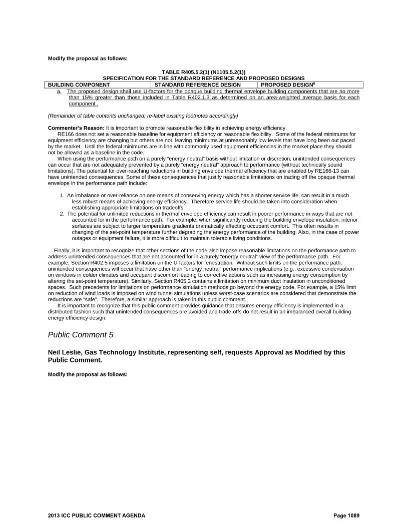
Modify the proposal as follows:
TABLE R405.5.2(1) (N1105.5.2(1)) SPECIFICATION FOR THE STANDARD REFERENCE AND PROPOSED DESIGNS
BUILDING COMPONENT STANDARD REFERENCE DESIGN PROPOSED DESIGNa a. The proposed design shall use U-factors for the opaque building thermal envelope building components that are no more
than 15% greater than those included in Table R402.1.3 as determined on an area-weighted average basis for each component .
(Remainder of table contents unchanged; re-label existing footnotes accordingly) Commenter’s Reason: It is important to promote reasonable flexibility in achieving energy efficiency. RE166 does not set a reasonable baseline for equipment efficiency or reasonable flexibility. Some of the federal minimums for equipment efficiency are changing but others are not, leaving minimums at unreasonably low levels that have long been out paced by the market. Until the federal minimums are in line with commonly used equipment efficiencies in the market place they should not be allowed as a baseline in the code. When using the performance path on a purely “energy neutral” basis without limitation or discretion, unintended consequences can occur that are not adequately prevented by a purely “energy neutral” approach to performance (without technically sound limitations). The potential for over-reaching reductions in building envelope thermal efficiency that are enabled by RE166-13 can have unintended consequences. Some of these consequences that justify reasonable limitations on trading off the opaque thermal envelope in the performance path include:
1. An imbalance or over-reliance on one means of conserving energy which has a shorter service life, can result in a much less robust means of achieving energy efficiency. Therefore service life should be taken into consideration when establishing appropriate limitations on tradeoffs.
2. The potential for unlimited reductions in thermal envelope efficiency can result in poorer performance in ways that are not accounted for in the performance path. For example, when significantly reducing the building envelope insulation, interior surfaces are subject to larger temperature gradients dramatically affecting occupant comfort. This often results in changing of the set-point temperature further degrading the energy performance of the building. Also, in the case of power outages or equipment failure, it is more difficult to maintain tolerable living conditions.
Finally, it is important to recognize that other sections of the code also impose reasonable limitations on the performance path to address unintended consequences that are not accounted for in a purely “energy neutral” view of the performance path. For example, Section R402.5 imposes a limitation on the U-factors for fenestration. Without such limits on the performance path, unintended consequences will occur that have other than “energy neutral” performance implications (e.g., excessive condensation on windows in colder climates and occupant discomfort leading to corrective actions such as increasing energy consumption by altering the set-point temperature). Similarly, Section R405.2 contains a limitation on minimum duct insulation in unconditioned spaces. Such precedents for limitations on performance simulation methods go beyond the energy code. For example, a 15% limit on reduction of wind loads is imposed on wind tunnel simulations unless worst-case scenarios are considered that demonstrate the reductions are “safe”. Therefore, a similar approach is taken in this public comment. It is important to recognize that this public comment provides guidance that ensures energy efficiency is implemented in a distributed fashion such that unintended consequences are avoided and trade-offs do not result in an imbalanced overall building energy efficiency design. Public Comment 5 Neil Leslie, Gas Technology Institute, representing self, requests Approval as Modified by this Public Comment. Modify the proposal as follows:
2013 ICC PUBLIC COMMENT AGENDA Page 1089

Table R405.5.2(1) SPECIFICATION FOR THE STANDARD REFERENCE AND PROPOSED DESIGNS
BUILDING COMPONENT STANDARD REFERENCE DESIGN PROPOSED DESIGN
Heating systemsf, g Fuel type: same as proposed design Electric Efficienciesy: Electric: air-source heat pump with prevailing federal minimum standards Non-electric furnaces: natural gas furnace with prevailing federal minimum standards Non-electric boilers: natural gas boiler with prevailing federal minimum standards
Cooling systemsf, hg
Service water heatingf, g,h,i Fuel type: same as proposed design Electric
f. For a proposed design with multiple heating, cooling or water heating systems using different fuel types, the applicable standard reference design system capacities and fuel types shall be weighted in accordance with their respective loads as calculated by accepted engineering practice for each equipment and fuel type present. fg. For a proposed design without a proposed heating system, a heating system with the prevailing federal minimum efficiency shall be assumed for both the standard reference design and proposed design. gh. For a proposed design home without a proposed cooling system, an electric air conditioner with the prevailing federal minimum efficiency shall be assumed for both the standard reference design and the proposed design. i. For a proposed design with a nonstorage-type water heater, a 40-gallon storage-type water heater with the prevailing federal minimum energy factor for the same fuel as the predominant heating fuel type shall be assumed. For the case of a proposed design without a proposed water heater, a 40-gallon storage-type water heater with the prevailing federal minimum efficiency for the same fuel as the predominant heating fuel type shall be assumed for both the proposed design and standard reference design. Commenter’s Reason: The IECC has already chosen the right metrics for energy performance in Section R405.3:
1. Energy cost budget (for adopting authorities mainly concerned about the homeowner’s economic objectives), or 2. Source energy budget (for adopting authorities mainly concerned about the homeowner’s energy consumption impacts on
primary energy consumption). However, for these to be implemented in a fair and equitable manner, one critical additional step is needed: A single baseline building energy budget. This amendment provides the critical single baseline budget methodology to implement this code correctly and equitably. It is only by implementing the correct metrics correctly - i.e. through the single baseline methodology – that the IECC can avoid adverse effects and unintended consequences on users of the code. This amendment corrects the flawed multiple baseline systems tradeoff methodology in RE166-13. It establishes an all electric building as the starting point for all energy use comparisons under R405.3. Without these changes, it is not possible for the multiple baseline systems methodology in RE166-13 to be “energy neutral”. Any multiple baseline systems methodology is inherently biased against fuel choices. You must have a single baseline. Multiple baseline systems are also biased against any technology options that might have lower energy cost and higher source energy efficiency. This is especially true for water heating but also applies to space heating in northern climates. As currently written, RE166-13 establishes the reference design building energy cost budget or source energy budget AFTER fuel choices are made. Therefore it is energy biased because it treats different energy forms as if they are equal when they are not, thereby always favoring one fuel choice over another inappropriately. The multiple baseline system methodology in RE166-13 is inconsistent with the stated intent of the IECC to provide “model code regulations that will result in the optimal utilization of fossil fuel and nondepletable resources in all communities, large and small.” The current provisions treat various technology options as equivalent to each other even though there are demonstrable and meaningful differences in energy cost and source energy use among the fuel choice and technology options, especially for electric resistance and natural gas options. This results in suboptimal utilization of fossil fuels because significantly more coal and natural gas are burned in power plants to provide electricity for inefficient qualifying electric technologies than would be consumed by burning natural gas directly in the home using the more source energy efficient and lower energy cost gas technology. As currently written, RE166-13 inserts a dangerous “fuel bias” in the code that this amendment fully corrects by changing to fuel blind, single baseline compliance provisions. The revised tables and text completely decouple the proposed building design choices from the standard reference design building’s energy cost or source energy performance requirement. The reference energy and technology choices in the revised section were selected to provide a practical and effective requirement to meet the intent of the standard while still offering appropriate incentives for the best available technologies based on their energy cost or source energy benefits. By shifting to electric technologies for all baseline systems, this amendment allows determination of an equitable energy cost or source energy budget at a reasonable level of performance using compliant electric technology options.
2013 ICC PUBLIC COMMENT AGENDA Page 1090

The most useful comparison illustrating the inherent flaw in the RE166-13 methodology is a minimally compliant electric storage water heater compared to a minimally compliant gas storage water heater. Homes using NAECA minimum efficiency electric resistance storage water heating qualify equally as a NAECA minimum gas storage water heater, even though both the annual energy costs and primary energy consumption are much higher for the resistance water heater than for the gas water heater (typically twice as high). Based on a typical home in the midwest, annual energy use for an NAECA minimum electric resistance water heater is 3,920 kWH, while a NAECA minimum gas water heater uses 205 therms. Using average Missouri energy rates available from EIA of $0.098 per kWh and $1.05 per therm, the electric water heater annual cost of operation is $384, while the natural gas water heater costs only $215 per year, a 79% increase in the energy cost budget for the electric water heater. Using the respective source energy conversion factors of 3.16 and 1.1 in the IECC, the source energy consumption of the electric water heater is 42.3 MBtu while the source energy consumption for the gas water heater is only 22.6 MBtu, an 87% increase in the source energy budget for the electric water heater. RE166-13 considers them equal for compliance purposes because it uses a separate, biased reference home for determining compliance for electric water heating systems. The lower energy cost and source energy represent benefits to consumers and society, yet they are not rewarded in the RE166-13 methodology. It is this “best efforts” harmful bias that the proposed shift to a single baseline system methodology fully corrects.
There is another development in 2013 that corroborates this amendment and a shift to an equitable single baseline methodology for consistency. ASHRAE Standard 90.1-2013 (a deemed-to-comply option in IECC-2014) will include for the first time a new single baseline system methodology in the performance path for all new commercial buildings. This methodology is identical to the single baseline mechanical system methodology proposed in RE179. The 90.1 single baseline tables are more sophisticated than those in RE179 to accommodate the wide variety of building types and regional building practices in the commercial sector. By including the proposed methodology in the residential provisions of the 2014 IECC, the residential and commercial provisions will be internally consistent. Public Comment 6: Brian Dean, ICF International, representing the Energy Efficient Codes Coalition; Jeff Harris, Alliance to Save Energy; Harry Misuriello, American Council for an Energy-Efficient Economy (ACEEE); Bill Prindle, representing the Energy Efficient Codes Coalition; Garrett Stone, Brickfield, Burchette, Ritts & Stone, PC; Donald J. Vigneau, Northeast Energy Efficiency Partnerships Inc., request Disapproval Commenter’s Reason: We recommend disapproval of RE166. In RE166, NAHB proposes to reintroduce an enormous loophole into the IECC residential energy provisions by re-creating the opportunity to trade-off the efficiency of other elements of the building for heating, cooling, and water heating equipment that is better than the least efficient equipment permitted to be sold under federal law. The net result would be that the same, fairly efficient equipment now typically installed in new homes due to technology advances, market conditions, and consumer preferences would result in zero energy savings – because the energy savings from efficient equipment would disappear through the a leakier thermal envelope and other efficiency downgrades allowed by the proposed trade-offs. Reinstating the equipment trade-off loophole would be the single biggest step backward in energy efficiency proposed by any proponent in this cycle and should be rejected. Here is a summary of some of the many major problems with this NAHB proposal:
• The proposed trade-off would allow a massive reduction in the more permanent features of the building that affect energy efficiency (such as insulation, windows, building tightness and duct tightness) if reasonably efficient heating, cooling and hot water equipment is installed. Exchanging a weaker permanent envelope for much shorter-life equipment, which is likely to be installed anyway, is not reasonable. For example, a water heater with less than a 10 year life should not be used to reduce the amount of insulation or to trade-off for a leaky building – creating problems that will last for the life of the home. • Depending on the efficiency of the equipment installed and the climate zone, allowing equipment trade-offs could amount to up to 20% (or more) potential reduction from the requirements of the current code nationwide in any home where the equipment is above the federal minimum standard. Such a trade-off could be used to wipe out most of the specific efficiency improvements included in the 2009 and 2012 IECC. • The proponent does not offer good reasons for the IECC to reverse course and retreat on the issue of equipment trade-offs. Equipment trade-offs were removed from the IECC two code cycles ago; no trade-offs are permitted by the 2009 or 2012 IECC. Nothing significant has changed to justify going backward. In both of the previous code cycles, a majority of the IECC development committee and an overwhelming majority of the ICC’s governmental members voted to remove these trade-offs and then later, to keep them out of the IECC. Earlier this year, on a close 6 to 5 vote, the IECC residential energy committee, with 4 NAHB representatives out of 11 voters, recommended this NAHB proposal for approval. • The federal government has reviewed and approved for state and local adoption both the 2009 IECC and 2012 IECC, finding that the removal of the trade-offs improved the energy efficiency of the code. Since these equipment trade-offs are not allowed by the 2009 IECC, state or local adoption of the 2015 IECC with this added provision would appear to violate commitments made by the states, as a condition of receiving federal funding, to adopt the 2009 IECC and achieve 90% compliance. • Reinstating the trade-off will not help encourage code adoption, as some claim. Equipment trade-off provisions have been removed from the current code adopted in 2/3 of the states and numerous localities. As a result, numerous homes have been built nationwide without any discernible problems from elimination of the trade-off. Reinstating this trade-off would only serve to move all of these codes sharply backward. While the committee’s reason suggests that trade-offs are being
2013 ICC PUBLIC COMMENT AGENDA Page 1091

adopted locally on a widespread basis, no one has offered any evidence to substantiate that claim; the fact that 2/3 of states have adopted the 2009 or 2012 IECC without such trade-offs show that this claim has no basis in reality. In fact, we expect that reinstating the trade-offs would have the opposite effect -- many of the energy code supporters who currently support energy code updates would likely become strong opponents of adoption of a weakened 2015 IECC with such a trade-off. • On a technical basis, equipment trade-offs are fundamentally a problem because, unlike other features (such as the building envelope), state and local codes are prohibited by federal law from setting a reasonable performance baseline for such equipment. Because the federal government has sole authority to set standards for such mechanical equipment, it is appropriate that the IECC leave this issue to the federal government. Reintroducing trade-offs would move the IECC back into this area of primary federal jurisdiction: o For the code to establish a standard or baseline for federally-regulated equipment, it can only use federal minimum standards. o Federal minimum standards for each type of equipment have been set at different times, under different circumstances, and under a different process than model or state codes, and subject to various regulatory, legal and political constraints – including long lead times to introduce a new level and a requirement that the same level of efficiency apply to equipment in new construction and to replacement equipment for existing homes, where it is often more difficult and costly to accommodate the latest technology. o These federal minimum standards do not represent reasonable code baselines for efficient equipment comparable to baselines set in the code for other parts of the building. o Federal minimum standards establish the minimum level at which equipment can be purchased for any purpose nationwide and are far too inefficient as compared with current building practice, creating a major compliance loophole that allows builders to reduce efficiency in other parts of the building. o We are aware of no other baseline building feature in the energy code that can be traded-off that is set at the minimum level allowed to be sold under federal law. o Allowing equipment trade-offs based on federal minimums introduces a significant fuel bias, currently in favor of natural gas, because the gap between the federal minimum standard and the typical efficiency level determined by the market is currently much wider for gas equipment than electric equipment. This is well illustrated by the fact that in 2015 gas furnaces will have an artificially low 80 AFUE standard nationwide as compared to the more rigorous 8.2 HSPF standard for electric heat pumps. As a result, homebuilders with an equipment trade-off can find far more trade-off potential by choosing gas equipment. Even the federal government has recognized that 80 AFUE for gas furnaces is far too low and has unsuccessfully attempted to increase it.
• While supporters of this proposal attempt to justify it in the name of “flexibility,” this is just a euphemism for “loophole.” It is a loophole because the typical equipment being sold and installed is already far more efficient than the minimum standard. For example, if RE166 were approved, a builder could capitalize on the 90+ AFUE furnace they are likely already installing, and increase heating energy consumption by 10% to 15% (and energy costs paid by the homebuyer) by applying trade-offs to reduce thermal efficiency of the envelope. We estimate the total impact on code-covered energy uses from a trade-off for a 90+ AFUE furnace to range from 6% to 9% lost energy cost savings nationwide, depending on the choice between 90 AFUE and 96 AFUE, and up to 14% lost savings in the coldest climate zones. • As discussed in more detail below, a majority of gas furnaces sold in the US are 90+ AFUE. In states with colder climates, where the trade-off created by the efficient furnace is much greater, the number is far higher. On top of the furnace trade-off, the builder can also install a better hot water heater (with a relatively short operating life) for another, possibly even larger trade-off that further weakens the building envelope. • The proponent also argues that trade-offs are necessary to avoid discouraging efficient equipment. Yet there is no evidence that builders need the trade-off to encourage better equipment. High-efficiency equipment continues to improve and penetrate the market even though trade-offs are currently not allowed in most states. Moreover, in many jurisdictions, the builder or homebuyer qualifies for utility incentives for such equipment. Utility incentives for equipment in new homes are likely to go away if trade-offs are reinstituted, since utilities typically are not permitted by their regulators to subsidize free ridership. Elimination of utility incentives will undercut, instead of support, the installation of efficient equipment. • Similarly, the argument that equipment trade-offs are “energy neutral” touts a false equivalence by focusing on energy use on Day One and ignoring the use of energy over time. Replacing more permanent features with less permanent features is not energy neutral over time. Moreover, such an argument ignores the fact already noted above that the code is required to use minimum federal standards and cannot set reasonable levels of efficiency. • Use of more efficient equipment in lieu of other energy efficiency measures also creates numerous other problems. For example, trading off envelope features for equipment also results in:
o Less comfortable homes due to weaker building envelopes and the likelihood to use more energy by adjusting the thermostat to compensate; o Homes that are less resilient in the face of emergencies like hurricanes and snowstorms, where power or gas supply is no longer available and the homeowner is reliant on the building thermal envelope, not the equipment, to provide a habitable environment (the weaker the envelope, the greater the risk to the health and safety of the occupant); and o Higher equipment loads and peak demands, with added first-cost for more heating or cooling capacity and negative impacts on utility generation, transmission and distribution systems.
• Reinstituting equipment trade-offs will create a bias for the performance path and lead to a migration away from compliance through the simple prescriptive path; greater utilization of the much more complex performance path will substantially complicate code compliance and enforcement.
2013 ICC PUBLIC COMMENT AGENDA Page 1092

Many of these issues are discussed in more detail below. We call on the Governmental Members to vote to retain a reasonable energy code by rejecting NAHB’s efforts to take the code back to 2006.
1. Equipment trade-offs will create a huge energy efficiency loss for the nation and are not “energy neutral.”
Although states can set performance baseline requirements for efficiency for most building components, certain types of mechanical equipment, including heating, cooling, and water heating equipment, are subject to a rigid set of requirements under Federal law. If any state incorporates equipment into a performance equation, it is mandated under federal law to base any trade-off on federal minimum efficiencies, which are well below the typical efficiency of equipment installed in many cases. (This law was designed to preclude states from indirectly requiring the use of more efficient equipment than the federal minimum standard requires.) Using gas furnaces as an example, even if builders routinely install condensing natural gas furnaces with 90+% efficiency, the state is prohibited under federal law from requiring 90+% efficient furnaces or anything more efficient than the federal minimum – generally an 80% efficient gas furnace. This creates an enormous (greater than 10%) loophole between the baseline amount of heating energy used and the actual amount used by the equipment, allowing a substantial degrading of the efficiency of other measures when using the performance path.
When the IECC permitted an equipment trade-off in the past (pre-2009 IECC), this federal preemption of state equipment requirements created a trade-off gap that was routinely exploited to reduce the efficiency of other elements of the building. According to an analysis produced by ICF International modeling the effects of this proposal, the impact on building energy efficiency if this trade-off were permitted again would be substantial. In the following table, 5 different trade-off packages illustrate the magnitude of the resulting trade-off loophole that will reduce the long-term energy efficiency of the building.
2015 Federal Minimum Equipment Efficiency
Readily Available Equipment Efficiency
National Average Increase in
Energy Use
Example 1 - Natural Gas (90 AFUE Only)
Natural Gas Furnace 80 AFUE 90 AFUE 6%
Air Conditioner 13 SEER/14 SEER 13 SEER/14 SEER 0%
Water Heater 0.59 Gas DHW 0.59 Gas DHW 0%
National Average 6% Climate Zone Averages 0-9%
2015 Federal Minimum Equipment Efficiency
Readily Available Equipment Efficiency
National Average Increase in
Energy Use
Example 2 - Natural Gas (Moderate Efficiency Equipment)
Natural Gas Furnace 80 AFUE 92 AFUE 7%
Air Conditioner 13 SEER/14 SEER 16 SEER 2%
Water Heater 0.59 Gas DHW 0.67 Gas DHW 3%
National Average 12% Climate Zone Averages 9-13%
2015 Federal Minimum Equipment Efficiency
Readily Available Equipment Efficiency
National Average Increase in
Energy Use
Example 3 - Natural Gas (High Efficiency Equipment)
Natural Gas Furnace 80 AFUE 96 AFUE 9%
Air Conditioner 13 SEER/14 SEER 19 SEER 4%
Water Heater 0.59 Gas DHW 0.80 Gas DHW 9%
National Average 22% Climate Zone Averages 18-30%
2015 Federal Minimum Equipment Efficiency
Readily Available Equipment Efficiency
National Average Increase in
Energy Use
2013 ICC PUBLIC COMMENT AGENDA Page 1093

Example 4 - Electric (Moderate Efficiency Equipment)
Heat Pump 8.2 HSPF 8.5 HSPF 1%
Air Conditioner 14 SEER 16 SEER 2%
Water Heater 0.92 Elec DHW 0.95 Elec DHW 2%
National Average 5% Climate Zone Averages 3-10%
2015 Federal Minimum Equipment Efficiency
Readily Available Equipment Efficiency
National Average Increase in
Energy Use Example 5 - Electric (High Efficiency Equipment)
Heat Pump 8.2 HSPF 9.2 HSPF 3%
Air Conditioner 14 SEER 19 SEER 4%
Water Heater 0.92 Elec DHW 1.15 Elec DHW 13%
National Average 21% Climate Zone Averages 13-29%
The national average percentage numbers in the tables indicate the amount of energy savings at risk if a builder uses readily available mechanical equipment as a means of “trading off” elements of the thermal building envelope such as insulation or windows. Thus, if RE166 is successful, and equipment trade-offs are included in the IECC for heating, cooling, and water heating equipment available to be installed in homes in 2015, new homes would be built to a substantially less efficient standard.
As an example, in Climate Zone 3, further analysis conducted by ICF International shows that homes that use high efficiency heating, cooling and water heating equipment can trade-off ALL of the following measures: wall insulation from R-20 to R-11, infiltration from 3 ACH50 to 7 ACH50, window U-factor from 0.35 to 0.75, window SHGC from 0.25 to 0.50, and duct leakage from 4 CFM/100 SF to 10 CFM/100 SF. Even if the high-efficiency equipment were not being installed in any case, the proposed trade-off, claimed to be energy cost neutral in the first year, would result in larger equipment sizes (63% larger furnace and 80% larger air conditioner), higher peak demand (22% increase) and significant comfort reduction due to having a leakier home, with leakier ducts and more extreme temperature at the exterior surfaces of the home. The larger equipment sizes will increase the cost of future equipment purchases, the higher peak demand will continue to stress the electric grid and the comfort reduction will cause higher energy bills, occupant turnover and lower property values.
To restore the equipment trade-offs in the IECC amounts to an unnecessary and costly giveaway and a massive backslide in energy efficiency.
2. Energy efficient equipment will be installed even without a trade-off, so this provision represents an enormous loophole for builders and results in increased energy use, less comfort, and higher operating costs for all subsequent owners of the home. As can be seen in the chart below from the Consortium for Energy Efficiency (CEE) with data from AHRI, there has been
a steady growth in the number of 90%+ AFUE furnaces across the entire US. In addition to this long term trend, recent data from US EPA show that in 2011, 55% of the furnaces shipped in the US were 90%+ AFUE ENERGY STAR furnaces. At the local level, in more northern heating climates where the 90+ furnace will create the greatest trade-off opportunity, the number is obviously much higher. For example, the Energy Center of Wisconsin shows that 90% of all furnaces in Wisconsin are 90%+ AFUE as of the 4th quarter of 2011. The potential for abuse of the furnace trade-off alone is staggering.
2013 ICC PUBLIC COMMENT AGENDA Page 1094

3. Short-term “flexibility” should not come at the expense of permanent energy efficiency.
Despite the widespread adoption of the IECC with no equipment trade-offs for the last four years and the major problems with such trade-offs, some still argue that an equipment trade-off adds necessary “flexibility,” and that without these trade-offs, codes will not be adopted and buildings will not be constructed with efficient equipment. This argument ignores three important realities: (1) efficient buildings should have both an efficient thermal envelope AND efficient equipment; (2) efficient equipment, because of consumer demand, utility incentives, and market maturity, is already widely used even without code trade-offs; and (3) about two-thirds of the states have already adopted the IECC without any such trade-offs.
Allowing direct trade-offs for building mechanical equipment, typically with much shorter life spans than the structure itself, ignores the long-term value of the permanent thermal envelope. Well-insulated homes provide a cost savings stream for homeowners for a much longer period than HVAC equipment, which will have to be replaced several times over the lifetime of the home. While the IECC performance path analysis and other similar measures calculate the energy use or energy cost over a one year period, this is only a limited snapshot of the home’s lifetime. A true analysis of the impact on the eventual homeowner must consider the impact of various measures over the life of the home.
A good illustration of the long-term energy impact of equipment trade-offs is to assume two homes: the first built to the 2012 IECC with minimum federal equipment, and the second built using equipment trade-offs to reduce the thermal envelope of the IECC. It should be noted that this illustration only addresses the long-term impact and not the free-rider issue -- that many homes will have upgraded equipment already. In the first year, the two homes may use the same amount of energy (assuming the equipment performs per spec). However, as heating, cooling, and/or water heating equipment is replaced every 5 to 20 years, it is reasonable to expect that improved efficiencies will result in the equipment in both homes becoming the same over time – through a combination of updated federal standards and ongoing technology improvements and market forces – or at least that the less efficient equipment in the first home will improve more rapidly than the more efficient equipment in the second home (it is also possible that the home with the more efficient equipment will replace that equipment with less efficient units). As this transition happens, the 2012 IECC house will always outperform the trade-off house, because it will benefit both from the stronger thermal envelope and more efficient equipment once replacement occurs. In addition, the home relying upon more efficient equipment will also need to size the equipment larger, will generate higher peak loads and the homeowner will have a home that will not respond as well during emergencies where electricity or gas is unavailable.
4. The ICC should continue to stand behind its decisions over the past two code cycles to eliminate and keep equipment trade-offs out of the residential energy code. To restore equipment trade-offs in the 2015 IECC would not only be a significant setback in energy efficiency for states
adopting that code, but such a reversal of position would also undercut the credibility of the IECC. Despite efforts of some stakeholders at the state level, the vast majority of states do not currently allow trade-offs of equipment efficiency for thermal envelope efficiency. The states have followed the lead set by both the 2009 and 2012 versions of the IECC – that such trade-offs are unnecessary and no longer appropriate. Currently, at least 33 states have adopted either the 2009 or 2012 IECC without any equipment trade-offs (in other states, where the code is adopted by local government, in many cases the new codes have also been adopted without trade-offs).
Congress also endorsed the 2009 IECC by reference in federal law -- the 2009 American Recovery and Reinvestment Act (ARRA) – setting the 2009 IECC as the starting point for state code adoption and implementation. All fifty states committed to adopt a residential code that meets or exceeds the 2009 IECC (which does not contain an equipment trade-off) under ARRA, and received
2013 ICC PUBLIC COMMENT AGENDA Page 1095

over $5 billion in DOE State Energy Program grants in return. Adoption of equipment trade-offs would be inconsistent with this law and these commitments.
The U.S. Department of Energy explained some of the benefits of eliminating the equipment trade-off in its analysis of the 2009 IECC, when it found that the 2009 IECC version was an improvement over the 2006 version and found that the elimination of the trade-offs would likely result in energy savings in the home:
Because building envelopes have substantially longer lives than HVAC and/or water heating equipment, energy savings from envelope improvements may persist for many more years than comparable equipment improvements. Also, because high-efficiency equipment is already the predominant choice in many markets, disallowing envelope/equipment tradeoffs is likely to result in improved overall efficiency in many situations.
See 75 Fed. Reg. 54131, 54138 (Sept 3, 2010). A well-insulated thermal building envelope will yield substantial cost-savings benefits to a homeowner for the lifetime of
the home, and the IECC should not trade away these long-term benefits for short-term savings associated with HVAC trade-offs. Such an amendment could roll back the energy code requirements currently enforced in most states, and could negatively impact the nation’s energy conservation efforts for generations to come. We urge disapproval of RE166 and all other similar equipment trade-off proposals. RE166-13 Final Action: AS AM AMPC D
2013 ICC PUBLIC COMMENT AGENDA Page 1096

RE169-13 Table R405.5.2(1) (IRC Table N1105.5.2(1))
Proposed Change as Submitted Proponent: Gary MacFadden, National Electrical Manufacturers Association (NEMA) ([email protected]) Revise as follows:
TABLE R405.5.2(1) (N1105.5.2(1)) SPECIFICATIONS FOR THE STANDARD REFERENCE AND PROPOSED DESIGNS
BUILDING COMPONENT STANDARD REFERENCE DESIGN PROPOSED DESIGN
Heating systemsf, g
As proposed for other than electric heating without a heat pump. Where the proposed design utilizes ducted electric heating without a heat pump, the standard reference design shall be an air source heat pump meeting the requirements of Section R403 of the IECC—Commercial Provisions. Where the proposed design is for an electric heating system that does not use a duct system, the standard reference design shall be as proposed. Capacity: sized in accordance with Section R403.6
As proposed
(Portions of table not shown remain unchanged) Reason: As it is written, Table R405.5.2(1) requires a modeler to assume a heat pump system whenever a designer proposes to use “… other than electric heating without a heat pump,” i.e., electric resistance or electric radiant heating (collectively “ERH”) in a new residence. While perhaps serving a valuable function in some fashion (elimination of gaming where a modeler assumes an electric furnace for the reference house and then proposes a heat pump allowing a less stringent envelope), the limitation on use of ERH in the modeling is overly restrictive. ERH is available in many different applications and the performance characteristics of non-ducted ERH are very different from the performance characteristics of ducted heating systems, whether fueled by electricity, gas, or any other fuel. In addition to no duct energy losses, non-ducted ERH also enjoys significant energy savings from zoning. This proposal attempts to preserve the benefit of eliminating gaming while still recognizing the energy savings potential of non-ducted ERH. Substantiation: ERH is available in a number of different configurations, including electric furnace, baseboard, radiant and PTAC. For purposes of this proposal, however, only non-ducted ERH is being considered. The operational and energy consumption characteristics of ducted vs. non-ducted ERH are significant and are at the core of the rationale behind this code change proposal. Unfortunately, ducted and non-ducted ERH systems are often grouped together (as they are in the existing code language). Language like that found currently in Table R405.5.2(1) that requires a modeler to assume a heat pump in the reference house, even if the designer intends to use electric baseboard heating in the proposed house, has been in the IECC for many years. The justification cited historically for that modeling limitation is:
• That modelers will game the system by assuming ERH in the reference house but a heat pump in the proposed house, thereby allowing a less stringent envelope, and/or
• That a heat pump will consume on the order of half the energy of an electric furnace installed in the same house so the code should discourage designers from specifying ERH and instead should specify a heat pump.
With respect to the former of these justifications, the current language requiring the same equipment to be modeled in both the reference and the proposed designs denies any opportunity to game the system as described above.
2013 ICC PUBLIC COMMENT AGENDA Page 1097

That leaves the latter as the sole justification for the modeling restriction against using electric resistance heating as the equipment assumption in the reference house. To some extent, this seems appropriate. If, for instance, in a heating dominated climate, a designer is proposing to install a ducted electric furnace with central air-conditioning, then incenting that designer to use a heat pump instead would probably be expected to save significant amounts of energy at a relatively modest cost. But there are significant operational and energy consumption characteristics that distinguish ducted from non-ducted ERH as described in more detail below.
Ducted vs. non-ducted heating systems. Non-ducted ERH has significantly different operational and energy consumption characteristics from ducted heating systems.
Fan Power. Numerous studies over the last decade have identified furnace fan energy usage as more significant than before believed. As a result, the U.S. Department of Energy has initiated a rulemaking to establish a test procedure for determining furnace fan energy. Likewise, the Environmental Protection Agency now has an Energy Star rating for efficient furnace fans. Of course, non-ducted ERH like baseboard or radiant doesn’t use a fan. On this basis, a reasonable person could conclude that, all other things being held constant, a non-ducted ERH system (without a fan) would consume less energy than a ducted electric furnace with a fan.
Duct loss and fan induced infiltration. Energy losses through ductwork are recognized as significant and come from two distinct sources; air lost through ductwork to the outside and induced infiltration/exfiltration caused by duct pressurization. Air lost to the outside is self-explanatory and is, in fact, already recognized by the 2012 IECC (and earlier versions) in Table R405.5.2(2) where distribution system efficiency is discounted under certain common conditions. In addition, there is growing recognition that ductwork design can have a significant impact on infiltration/exfiltration. On this basis, a reasonable person could conclude that, all other things being held constant, a non-ducted ERH system would consume less energy than a ducted electric furnace.
Zoning. Ducted, central heating, whether it be a ducted heat pump, electric furnace, gas furnace or other, is designed to serve large areas, most often an entire house. Non-ducted ERH, on the other hand, generally divides a house up into numerous independently controlled zones. The energy efficiency benefits of zoning are well documented as it allows users to heat only those areas that are occupied resulting in significant savings. On this basis, a reasonable person could conclude that, all other things being held constant, a zoned, non-ducted ERH system would consume less energy than a ducted electric furnace.
Additional considerations. Few people would argue that, at the margin, a zoned, non-ducted ERH would be expected to consume fewer btu’s over the course of a winter than a ducted electric furnace. In addition to these operational differences, however, (no fan energy, no duct losses, benefits of zoning), there are other reasons why ERH should be treated differently from ducted heating systems as noted below.
Cooling. There are still a non-trivial amount of new homes built in the United States every year without central cooling. According to the EIA, over 800,000 new homes were built between 2000 and 2009 without air-conditioning. A recent study in the Pacific Northwest revealed a relationship between increased use of cooling energy in homes that use heat pumps vis-à-vis electric furnaces. While there are a number of potential explanations, at least one explanation is that people using ERH consciously decline to install air conditioning. Thus, incenting the use of heat pumps over ERH may have the unintended result of increasing summer cooling energy.
Cooling dominated climate. In cooling dominated climates, with relatively few heating degree days (DOE Climate Zones 1 & 2), driving a builder to use a heat pump which would save relatively little – if any – heating energy due to the warm climate would result in fewer dollars for that builder to spend on other things like more attic insulation or higher SEER air-conditioning – something that would actually result in energy savings.
Non-ducted ERH has significantly different operating characteristics than ducted heating systems. With respect to the assumption that a heat pump system will consume less than half the btus’s of an electric resistance heating system because the heat pump has a COP of 2 or better, this assumption may be valid for a comparison between a ducted heat pump and a ducted electric resistance furnace, but it not accurate for non-ducted, zoned ERH (See Note 1 below)
In a study conducted by the National Association of Home Builders Research Center for the U.S. Department of Energy, an occupied house in the Washington, D.C. area was monitored for performance over a winter. The house contained three distinct heating systems; central electric heat pump, electric radiant heat, and electric baseboard heat. After the data was weather normalized, it revealed that, under actual homeowner controlled conditions, the electric radiant system used 33% percent less energy than the heat pump system and 52% less than the electric baseboard system. Thus, the heat pump only saved about 36% the energy consumed by the electric baseboard system.
Heat pumps are a great option when a person wants a central, ducted hearing and cooling system but they having different operating characteristics from a non-ducted ERH system. Note 1. Recent field data from a large survey of homes suggests that the actual (vs. theoretical) relationship may not be as well understood as previously believed. See study at http://www.nwcouncil.org/energy/rtf/meetings/2009/04/Draft%202008%20NEEM%20Study_040608.pdf (p. 21) where observed heat pump energy savings were far short of expectations and the report said
“For the heat pump cases, however, the apparent similarity between electric resistance and heat pump systems suggest minimal savings for the more efficient heat pump option. Some form of behavioral ―takeback‖, poor heat pump installations or increased summer cooling load for heat pumps vis-à-vis resistance houses seem the likeliest explanations. Given that a number of the zone 1 sites (e.g.: Medford, Oregon; Yakima, Washington; and The Dalles, Oregon), have cooling climates, the latter seems plausible. A possible alternate contributing explanation is that these heat pump units do not in fact achieve an average COP of as much as 2 under actual operating conditions. Field notes from heat pump cases in the Oregon sample (a high percentage of heat pumps) mentioned occupants who complained about a lack of comfort to their heating contractor and were told by their heating contractors to switch the heat pumps to run in electric resistance heating mode.”
Bibliography Study of manufactured housing in the Pacific Northwest, http://www.nwcouncil.org/energy/rtf/meetings/2009/04/Draft%202008%20NEEM%20Study_040608.pdf
2013 ICC PUBLIC COMMENT AGENDA Page 1098

NAHB Radiant Heat Study, http://www.toolbase.org/PDF/CaseStudies/enerjoy_case_study.pdf For an Alliance to Save Energy video on the benefits of zoning see http://www.energynow.com/video/2011/11/16/home-efficiency-tips-heating-and-cooling-zones where the moderator quotes the Department of Energy as saying that zoning can save up to 30% on home heating and cooling bills. For information on duct leakage see http://www.greenbuildingadvisor.com/blogs/dept/musings/duct-leakage-testing. Also see EPA Energy Star guidance at http://www.energystar.gov/index.cfm?c=home_improvement.hm_improvement_ducts. For information on fan induced infiltration into buildings see http://www.buildingscience.com/documents/digests/bsd-014-air-flow-control-in-buildings/files/bsd-014_air-flow-control_ed.pdf. For an article on the significance of furnace fan energy see http://aceee.org/proceedings-paper/ss08/panel02/paper09. Also see U.S. Department of Energy Appliance Efficiency furnace fan docket at http://www1.eere.energy.gov/buildings/appliance_standards/residential/furnace_fans.html. Cost Impact: The code change proposal will not increase the cost of construction.
R405.5.2(1)T #2-EC-MCFADDEN.DOC
Committee Action Hearing Results
Committee Action: Disapproved Committee Reason: This proposal would have the effect of possibly doubling the heating use of the house by allowing the energy budget to be higher. Assembly Action: None
Individual Consideration Agenda
This item is on the agenda for individual consideration because a public comment was submitted. Public Comment: Gary MacFadden, The National Electrical Manufacturers Association, representing NEMA, requests Approval as Submitted. Commenter’s Reason: Table 405.5.2(1) establishes criteria for calculating energy budgets for persons that would like to use the IECC’s performance path to demonstrate code compliance. As part of that process the Table sets out minimum requirements for the modeling of equipment. For all equipment except electric resistance heating, the space heating equipment that is modeled in the reference house must be identical to equipment modeled in the proposed house.
With electric resistance heating, however, the Table requires the modeling of a heat pump for all homes using electricity to heat – even if the owner plans to use zoned electric resistance heat for space heating. In our original support of RE169 we provided voluminous documentation of the many differences between non-ducted electric resistance heating (like zoned baseboard and radiant panels) and the operation of a heat pump.
Without repeating those citations, we would like to summarize as follows:
1. Electric baseboard has no duct losses, 2. Electric baseboard consumes no fan energy, 3. Electric baseboard causes no fan induced home infiltration or exfiltration, 4. Electric baseboard complements the growing production of electricity from renewable sources like wind and solar, 5. Unlike central heating systems, electric baseboard enjoys room-by-room zoning allowing efficient operation.
Electric baseboard heating is not the best choice in all applications --- but it is the right choice in many instances. For example, over 1,000,000 homes have been built over the last 10 years that do not use air conditioning!! Incenting people that don’t want air conditioning to use a heat pump is not a good policy given growing concerns over summer peak power demands. In another example, the Founder of the Passive House Institute chose to heat her new house with electric baseboard.
This proposal would simply match modeling of electric baseboard heating to those circumstances where a person elects not to use ducted central heating and they don’t want air conditioning.
RE169-13 Final Action: AS AM AMPC D
2013 ICC PUBLIC COMMENT AGENDA Page 1099

RE170-13 Table R405.5.2(1) (IRC Table N1103.5.2(1))
Proposed Change as Submitted Proponent: Don Surrena, CBO, National Association of Home Builders (NAHB) ([email protected]), and Mark Halverson, APA-The Engineered Wood Association & Loren Ross, The American Wood Council. ([email protected]). Note: RE177 was listed in the code change monograph separately with Mark Halverson as the proponent. Since RE177 was a duplicate of RE170, RE177 was withdrawn, and Mark Halverson is listed as a co-proponent on this code change proposal. Revise as follows:
TABLE R405.5.2(1) (N1103.5.2(1)) SPECIFICATIONS FOR THE STANDARD REFERENCE AND PROPOSED DESIGNS
BUILDING COMPONENT STANDARD REFERENCE DESIGN PROPOSED DESIGN
Glazinga
Total areab =
(a) The proposed glazing area; where proposed glazing area is less than 15% of the conditioned floor area.
(b) 15% of the conditioned floor area; where the proposed glazing area is 15% or more of the conditioned floor area.
Orientation: equally distributed to four cardinal compass orientations (N, E, S, & W)
U-factor: from Table R402.1.3
SHGC: From Table R402.1.1 except that for climates with no requirement (NR) SHGC = 0.40 shall be used.
Interior shade fraction: 0.92-(0.21 × SHGC for the standard reference design)
External shading: none
As proposed
As proposed
As proposed
As proposed
0.92-(0.21 × SHGC as proposed)
As proposed
(Portions of table not shown remain unchanged) Reason: (Surrena) Walls generally perform better thermally than windows. Currently in the code there is no incentive in the performance path for the building designer to optimize the window area in order to save energy and provide daylighting, egress and views that makes for a safe and comfortable house. These modifications will provide the building designer the ability to reduce window area and get credit for the energy saved. As this section is currently written, the house is penalized for having more than 15% window area yet receives no credit toward code compliance when the window area is reduced below 15%. This change rectifies this disparity and makes the performance path a more representative of actual energy use. (Halversen) The greatest thermal break in our wall systems is glazing. While glazing areas greater than 15% of the floor area are penalized for reduced energy efficiency, glazing areas less than 15% are not recognized for increasing energy efficiency. Homes with a lower percentage of windows and doors generally perform better than the code minimum (15%); therefore, these homes should get credit for the additional energy efficiency. This will enhance the readability of the code while making it easier to understand, more equitable, and provide flexibility to builders and architects.
Every avenue must be explored when elevating energy code efficiency to the next level, and this offers an efficiency increase that has not yet been recognized in the code.
We ask the support of the committee for this proposal.
2013 ICC PUBLIC COMMENT AGENDA Page 1100

Cost Impact: The code change proposal will not increase the cost of construction.
R405.5.2(1)T #2-EC-SURRENA.DOC
Committee Action Hearing Results Committee Action: Disapproved Committee Reason: This proposal would penalize small dwellings where the percentage of openings must necessarily be larger than 15%, and they cannot take advantage of the tradeoff. This also has the effect of increasing the energy budget by lowering the amount of loss in the standard referenced design. RE164-13 is the better approach for this issue. Assembly Action: None
Individual Consideration Agenda
This item is on the agenda for individual consideration because public comments were submitted. Public Comment 1: Don Surrena, National Association of Home Builders, and Tim Ryan, representing the International Association of Building Officials, request Approval as Submitted. Commenter’s Reason: Building walls generally perform much better thermally than windows. This code change proposal will provide the building designer the option to reduce window area and get the appropriate energy credits for the amount of energy saved. As this section is currently written, the home designer is penalized for having more than 15% window area, but receives no energy credits toward code compliance when the window area is reduced below 15%. This code change proposal fixes this disparity and makes the performance path a more representative of actual energy use. Public Comment 2: Paul Coats and Mark Halverson, representing APA-The Engineered Wood Association/American Wood Council request Approval as Submitted. Commenter’s Reason: Assuming that the energy code is being developed to save energy, it seems obvious that decreasing the area of windows (which are typically only an R3 or less) in a wall system and increasing the opaque wall areas (R13, R20 and R20+5) should be recognized as an energy-saving measure in the code. Regardless of the climate zone, window and door areas do not have the thermal resistance of opaque walls. It is even difficult to advocate the advantages of passive heat gains during the colder weather months given the fact that SHGC values have no minimum limitations in any of the climate zones. The International Energy Conservation Code must recognize that buildings with fewer windows save energy and incentivize the use of fewer windows. The committee commented during the hearings that they feared that the builders would somehow “game the system” by using the energy credit for less windows to off-set energy efficiency in other areas of the structure. However, the trading-off of the energy efficiencies of the building components and systems is the basis of performance paths. To hinder the builders’ and designers’ abilities to meet energy efficiency in any way that they choose creates inequities in the code that lead to preferential treatment of some products and systems and limitations to market access for other products and systems. The committee’s reason statement endorsed the approach of RE 164-13 which removes all area restrictions for windows and doors in the performance path. This position, along with denying energy savings from reduced window area, indicates that the committee thinks that the area of windows is not related to energy savings. Apparently, the committee accepted the proponent’s reason statement in RE 164-13 to “keep it simple and keep it energy efficient.” Simplicity is good, but the impact on energy efficiency is not acceptable. The proponent of RE164-13 claimed that “as windows get more efficient, the window area matters less” and that windows in the market in colder climates “may be as good as a ‘normal’ wall”. In reality, the thermal performance of code-conforming windows is not comparable to opaque walls. In the 2006 IECC windows ranged in U-factors from U-1.2 to U-0.35 and in the 2012 code windows ranged from U-NR to U-0.32. In contrast, U-factors for walls range from 0.082 to 0.048. In the 2012 IECC, walls are typically 6 times more energy efficient than windows. The least insulated walls (Climate Zone 1) are 4 times more efficient than the windows required in the coldest climate zone (Climate Zone 8). There is no indication that window U-factors will approach the U-factors of opaque walls in the near term. It is absurd to remove the weakest link in heat resistance from consideration in the performance path.
2013 ICC PUBLIC COMMENT AGENDA Page 1101

While continuous insulation advocates continue to be concerned about the “thermal break” of wood wall framing materials, the even greater thermal break of windows and doors will now be unrestricted in area. The thermal resistances through the wood framing path in an opaque wall are calculated as R6.8 for 2x4 walls and R9.3 for 2x6 walls, while window values hover around an R3 level or less. It would appear that the code is moving in a direction that is neither product neutral nor encouraging energy efficiency. We urge the body’s support of this code change proposal that is product neutral and saves energy. RE170-13 Final Action: AS AM AMPC D
2013 ICC PUBLIC COMMENT AGENDA Page 1102

RE171-13 Table R405.5.2(1) (IRC Table N1105.5.2(1))
Proposed Change as Submitted Proponent: Jeremiah Williams / U.S. Department of Energy ([email protected]) Revise as follows:
TABLE R405.5.2(1) (N1105.5.2(1)) SPECIFICATIONS FOR THE STANDARD REFERENCE AND PROPOSED DESIGNS
BUILDING COMPONENT STANDARD REFERENCE DESIGN PROPOSED DESIGN
Glazinga
Total area (exclusive of glazing of thermally isolated sunrooms)b =
(a) The proposed glazing area; where proposed glazing area is less than 15% of the conditioned floor area.
(b) 15% of the conditioned floor area; where the proposed glazing area is 15% or more of the conditioned floor area.
Orientation: equally distributed to four cardinal compass orientations (N, E, S & W). U-factor: from Table R402.1.3 SHGC: From Table R402.1.1 except that for climates with no requirement (NR) SHGC = 0.40 shall be used. Interior shade fraction: 0.92-(0.21 × SHGC for the standard reference design) External shading: none
As proposed As proposed As proposed As proposed 0.92-(0.21 × SHGC as proposed) As proposed
Thermally isolated sunrooms
None Geometry and orientation: same as proposed Opaque ceiling and wall insulation: in accordance with Section R402.2.12 Opaque wall solar absorptance = 0.75 Opaque wall emittance = 0.90 Fenestration U-factor: in accordance with Section R402.3.5
As proposed As proposed As proposed As proposed As proposed
2013 ICC PUBLIC COMMENT AGENDA Page 1103

(Portions of table not shown remain unchanged) Reason: In the current code, there is no connection between the performance path and the prescriptive requirements for thermally isolated sunrooms. Including thermally isolated sunrooms in the standard reference design, if present in the proposed design, ensures a proper comparison against the code’s associated prescriptive requirements and minimizes confusion about the applicability of the sunroom specifications for homes complying via the performance path. Cost Impact: The code change proposal will not increase the cost of construction.
R405.5.2(1) #3-EC-WILLIAMS.DOC
Committee Action Hearing Results Committee Action: Disapproved Committee Reason: This proposed change would represent a significant increase in the energy budget for the standard referenced design. Assembly Action: None
Individual Consideration Agenda
This item is on the agenda for individual consideration because a public comment was submitted. Public Comment: Jeremiah Williams, U.S. Department of Energy requests Approval as Modified by this Public Comment. Modify the proposal as follows:
TABLE R405.5.2(1) (N1105.5.2(1)) SPECIFICATIONS FOR THE STANDARD REFERENCE AND PROPOSED DESIGNS
Glazinga Total area (exclusive of glazing of thermally isolated sunrooms)b =
…
As proposed …
Thermally isolated sunrooms Geometry, area, and orientation of fenestration, opaque
wall, opaque ceiling/roof, and floor/foundation area: same as proposed Opaque ceiling and wall insulation: in accordance with Section R402.2.12 Opaque wall solar absorptance = 0.75 Opaque wall emittance = 0.90 Fenestration U-factor: in accordance with Section R402.3.5 Fenestration SHGC:in accordance with Table R402.1.1
As proposed
(Portions of code change proposal not shown remain unchanged) Commenter’s Reason: In the current code, there is no connection between the performance path and the prescriptive requirements for thermally isolated sunrooms. Including thermally isolated sunrooms in the standard reference design, if present in the proposed design, ensures a proper comparison against the code’s associated prescriptive requirements and minimizes confusion about the applicability of the sunroom specifications for homes complying via the performance path. This Public Comment addresses deficiencies raised at the Committee Action Hearing. SHGC was added to the modeling requirements. This proposal, as modified by this Public Comment, does not alter the stringency of the code, because the standard
2013 ICC PUBLIC COMMENT AGENDA Page 1104

reference design is set to have the prescriptive requirements in section R402 of the code. This is consistent with the fundamental approach used to establish compliance via the performance path. DOE posted its draft proposals and public comments for the IECC on its Building Energy Codes website prior to submitting to the ICC. Interested parties were provided a 30 day public review in June 2013, for which notice was published in the Federal Register (Docket No. EERE-2012-BT-BC-0030) and announced via the DOE Building Energy Codes news email list. In response to stakeholder input, DOE revised its proposals and public comments, as appropriate, and submitted to the ICC.
For more information on DOE proposals and public comments, including how DOE participates in the ICC code development process, please visit: http://www.energycodes.gov/development. RE171-13 Final Action: AS AM AMPC D
2013 ICC PUBLIC COMMENT AGENDA Page 1105

RE172-13 R405.1 (IRC N1105.1), Table R405.5.2(1) (IRC Table N1105.5.2(1)), R405.7 (NEW) (N1103.7 (NEW)), R405.8 (NEW) (N1103.8 (NEW)), R405.9 (NEW) (N1103.9 (NEW)), R405.10 (NEW) (N1103.10 (NEW))
Proposed Change as Submitted Proponents: Craig Conner, Building Quality, representing self ([email protected]), Gary Klein, Affiliated International Management, LLC, representing self ([email protected]), Gerald Van Decker, RenewABILITY, representing self ([email protected]), Philip Fairey, Deputy Director, Florida Solar Energy Center ([email protected]) Revise as follows: R405.1 Scope. This section establishes criteria for compliance using simulated energy performance analysis. Such analysis shall include heating, cooling, and service water heating energy only.
TABLE R405.5.2(1) (N1105.5.2(1)) SPECIFICATIONS FOR THE STANDARD REFERENCE AND PROPOSED DESIGNS
BUILDING COMPONENT
STANDARD REFERENCE DESIGN
PROPOSED DESIGNm
Internal gains
IGain = 17,900 + 23.8 x CFA + 4104 x Nbr 16,600 + 12 x CFA + 8080 x Nbr (Btu/day per dwelling unit) Nbr=Number of bedrooms
Same as standard reference design.
Service Water Heating f,g,h,j ,l, m
As proposed Fuel type: same as proposed design Efficiency: in accordance with prevailing federal minimum standards Use: gal/day = 20 + (10 × Nbr) Tank temperature: 120°F Use: same as proposed design Nbr=Number of bedrooms
As proposed As proposed Use: Standard reference x SWHF gal/day = 30 + (10 × Nbr) Same as standard reference Design
2013 ICC PUBLIC COMMENT AGENDA Page 1106

BUILDING COMPONENT
STANDARD REFERENCE DESIGN
PROPOSED DESIGNm
Clothes washer k, n
550 kWh/yr
Either of the following: Same as standard reference design or (300 × IMEF), kWh
Lighting
300 + (0.43 x CFA), kWh/yr CFA = Conditioned floor area (ft2)
Either of the following: Same as standard reference design and lighting is in compliance with Section R404.1 or 1 kWh/yr per watt of installed lighting
Refrigeratorn
500 kWh / year
Either of the following: Same as standard reference design or As proposed
(Portions of table not shown remain unchanged) j. SWHF = Service water heating factor. SWHF is the product of multiplying the hot water distribution efficiency factor and the drain water heat recovery factor.
Hot water distribution efficiency factor:
= 0.80 where a demand recirculation water system is installed for the hot water distribution system and the volume in the piping from the circulating hot water piping to the termination of the fixture supply for every fixture is less than or equal to 0.19 gallons (0.71 liters).
= 0.9
where the water volume in the piping from the water heater to the termination of the fixture supply for every fixture is less than or equal to 0.5 gallons (1.89 liters).
= 1.0
where the other conditions are not met. Drain water heat recovery factor:
= (1 – (Drain water heat recovery unit efficiency x 0.36)) where one or more DWHR units receive the drain water from all showers in the building and the DHWR units are in accordance with Section R405.10.
= (1 – (Drain water heat recovery unit efficiency x 0.18))
where a DWHR unit receives the drain water from the primary shower but not all showers in the building and the DHWR unit is in accordance with Section R405.10.
2013 ICC PUBLIC COMMENT AGENDA Page 1107

= 1.0
where the other conditions are not met. k. IMEF = integrated modified energy factor for the proposed clothes washer l. Where more than one drain water heat recovery unit is used, the average efficiency of all drain water heater recovery units shall
be used in the performance calculation. m. Proposed design equipment and device efficiencies shall be in accordance with Section R405.7. n. Where the proposed design includes more than one refrigerator or clothes washer, the energy use shall be summed. Add new text as follows: R405.7 (N1103.7) Equipment and device verification. The efficiency of the equipment and devices used for the proposed design shall be specified in the construction documents. The installed equipment and devices shall not be less than the efficiency specified in the construction documents. The efficiency of equipment and devices shall be indicated by the manufacturer on a label or on a specification sheet attached to the equipment or device. The equipment or device efficiency shall be readily observable for inspection after the equipment or device is installed. This section shall apply only to equipment and devices where the proposed design is different than the standard reference design for that equipment or device. R405.8 (N1103.8) Hot water distribution verification. The construction documents for the building shall show plumbing diagrams that indicate water heaters, plumbing fixtures, plumbing appliances, pipe sizes and layouts for hot water supply and hot water circulating system piping. The layouts shall indicate the volume of water in the branches of the piping from the nearest source of hot water piping to the termination of the fixture supply pipe. This section shall apply only where the proposed design for the hot water distribution system is different than the standard reference design for the hot water distribution system. R405.9 (N1103.9) Lighting verification. A schedule, by room, of lighting fixtures and lamps indicating the wattage of each fixture shall be provided for interior lighting and garage lighting. The sum of wattages on the schedule shall be used for the proposed design. This section shall apply only where the proposed design for lighting is different than the standard reference design for lighting. R405.10 (N1103.10) Drain water heat recovery units. Drain water heat recovery units shall be tested by the manufacturer for efficiency and pressure loss at a flow rate of 2.5 gpm (9.5 L/m) through each water side flow path. The water side pressure loss shall not exceed 3 psi (20.7 kPa) for each flow path. The manufacturer shall indicate the efficiency and pressure loss of the unit on a label or specification sheet attached to the unit. This section shall apply only where the efficiency of drain water heat recovery is used in the performance calculation. Reason: This code change proposal -- expands the performance calculation to include options for energy savings from water heating, lighting, refrigerators and clothes washers. -- updates water use, lighting and internal gains equations in the performance calculation table to reflect current equipment, and -- specifies efficiency measures in a way that makes them enforceable.
The options in this proposal were picked because they have significant impact, can be specified in simple terms, and can be specified based on existing tests or standards. The performance section user can choose to use or not use any of these options. Options not used become neutral in the performance calculation, because the standard reference design and the proposed design become the same.
This proposed change includes four options for saving the energy used for service water heating: -- efficient water heater, -- efficient water heating distribution, also know as efficient hot water pipe layout, -- recovery of heat from drain water, and -- efficient clothes washer The first hot water energy saving option is a water heater that exceeds the minimum Federal efficiency standard for water heaters. The efficient water heater is computed as it was in the 2006 IECC. Water heaters exceeding minimum Federal efficiency are widely available.
2013 ICC PUBLIC COMMENT AGENDA Page 1108

The second source of hot water savings is limiting the waste in delivering hot water to the point of water use. This does not limit hot water use, rather it limits hot water waste. Hot water must first flow through the pipes from the water heater to the point of use. Unless hot is water already in the pipes, the cool water in the pipes must be emptied and replaced by hot water, which wastes water. After use the hot water left in the pipes cools down, unless there is another use within about an hour. The cool down is wasted heat. Thus hot water distribution routinely wastes both energy and water. Piping layouts with less water volume between the water heater and water use inherently waste less heat and less water. The two “distribution efficiency factors” and their savings for limiting wasted hot water are adapted for the IECC from the ANSI consensus standard ICC 700-2012 (National Green Building Standard). The factors, 0.90 and 0.80, represent a 10% and 20% savings respectively. As an additional benefit, limiting hot water waste means better performance, because the hot-water-user’s wait for the “cold water to get hot” is the time it takes to replace cool water in the pipes with hot water and smaller water volumes are replaced more quickly. The third source of hot water energy savings is heat recovery from drain water. Drain water heat recovery (DWHR) works particularly well where heated water flows down the drain at the same time as water flows in that needs to be heated; this “coincident flow” occurs in homes with showering and lavatory use. Performance of a DWHR unit is characterized by both efficiency and pressure loss. It is important to ensure that DWHR devices do not have high pressure loss in order to minimize the impact on water pressure in the home. Given the available DWHR efficiencies, savings are typically 10% to 35% of the energy used for heating water. To put the “0.36” in the equation in perspective, the “coincident flow” in a residence is typically 50%-70% of the hot water use, so 0.36 (36%) times the device’s efficiency is similar to saying the unit works well on showers and lavatories, and may also recover a portion of the rest of the hot water use in the home. The 0.36 also covers natural drain water heat loss and assumes the “worst-case” plumbing scenario for DWHR devices. This calculation of savings is conservative. Over 25,000 drain water heat recovery units have been installed in homes in Canada and the United States.
The fourth source of water heating savings is clothes washers. Clothes washer efficiency is rated by the Federally required IMEF rating.1 The minimum Federal requirement at the time of the 2015 IECC will be an IMEF of 1.84.2 IMEF is energy use divided by washer volume. The Federal standard presumes 295 loads per year. So the base case, the standard reference design, for a typical 3.5 cubic foot washer is 1.84 x 3.5 x 295 = 550 kWh/yr (rounded). One of the biggest savings in new clothes washers comes from the reduced water in washed clothes, which saves energy in clothes drying. The effect of reduced clothes dryer energy is included in the Federally required IMEF rating.
The hot water use equation in the IECC is updated to reflect lower water use rates. The IECC water use equation has not been updated since the 1995 Model Energy Code, making the equation over 20 years old by the time of the 2015 IECC. Water use per residence has been falling for a long time.3 Various sources estimate the decline in water use at 0.5 to 3% per year. The reduction in water use is expected to continue.4 The primary factors that contribute to the reduction in hot water use since the 1995 IECC are more efficient washing machines and dishwashers, and water-use efficient faucets and showers, all a result of the National Appliance Energy Conservation Act that took effect in the mid 1990s.
This proposal adds lighting as an optional part of the performance calculation. Lighting requires a “base case” in the standard reference design and a calculation based on the proposed design. The standard reference design lighting energy use is based on the RESNET equation6 for interior lighting energy use in homes, including garages. The standard reference equation is adjusted6 for the higher percentage of efficient lighting (high efficacy lighting) required by the IECC.
The proposed lighting energy use is calculated as hours of use times watts. An average use of 1000 hours per year (2.75 hours per day) is within the reported range for actual light use5 and is presumed. The proposed lighting annual energy use is simply 1 kWh per watt of installed lighting.
To “opt out” of the lighting calculation, the code user meets the Section R404.1 lighting requirements, then the performance calculation presumes the standard reference design and the proposed design are the same for lighting.
This proposal adds a refrigerator option as part of the performance calculation. It requires a “base case” in the standard reference design and a proposed refrigerator. The refrigerator base case is fixed at 600 kWh/yr. For comparison, a 3 bedroom house in the RESNET procedures would have a base case energy use of 691 kWh/yr. Federal minimum refrigerator efficiency standards will increase in 2014 8,9. Refrigerators are reduced about 25% in 2014 by the upcoming Federal standard, so 600 kHz/yr is reasonable as a “base case”.
The internal gains equation is updated by this change. Internal gains are heat from various sources besides the heating system, including heat produced as a byproduct of lighting and refrigeration. The IECC internal gains equation has not been updated since the 2003 IECC, so it will be more than 10 years old in the 2015 IECC. Big reductions have come from more efficient lighting, as required by Section R404.1. Refrigerators have also reduced their energy use greatly in the last ten years, with a further reduction coming in 2014. The new internal gains equation is revised based on the lighting and refrigeration specifications in this proposed change.10
One big issue with having options for more efficient equipment and devices is inspection and verification. The efficiency used must be easy to verify. A new section, Section R405.7, requires that the efficiency used in the proposed design be specified on construction documents. Any equipment or device that meets or exceeds the efficiency marked on construction documents will be acceptable. Code enforcement staff does not have the time to look up equipment or device model numbers to find an efficiency rating in a data base or book; therefore, the new Section R405.7 requires that the installed efficiency be “readily observable”, which is very similar to “readily accessible”. “Readily observable” is the term used in Section R303.1.2 and C303.1.2 for the insulation R-value.
The performance calculation user may choose to calculate lighting energy use based on the installed watts of lighting. Lighting wattage will need to be verifiable, as lighting savings are based on the watts of installed lighting. Code officials are unlikely to have the time to count watts in a house. Where the proposed lighting energy use is calculated, this change requires a schedule of lighting fixture/lamp watts divided by rooms, which gives enough detail to spot check a house. If the proponents of this proposal were verifying lighting, they would pick a room and spot check it.
The performance calculation user may choose to use a more efficient hot water distribution system based on limiting the hot water volume in pipes. Hot water piping volume will need to be verified. Code officials are unlikely to have the time to check all the pipe volume calculations in a house. This change requires plumbing layouts with pipe sizes on the construction documents. For each branch the fixture with the largest hot water supply volume and that fixture’s volume is identified on the plans. This level of
2013 ICC PUBLIC COMMENT AGENDA Page 1109

detail will enable spot checking of a plumbing branch. If the proponents of this proposal were verifying efficient plumbing layout, they would pick one of the plumbing branches and check it.
The measures of efficiency in this change are based on existing tests and standards. The water heater efficiency is measured by the EF (energy factor), which is a rating required by Federal law. The clothes washer efficiency is measured by the IMEF (integrated modified energy factor), which is a rating required by Federal law. The refrigerator efficiency is measured by annual energy use (kWh), which is a Federal rating required to be on the Energy Guide label (yellow labels). The hot water distribution efficiency (efficient piping) is adapted from ICC 700-2012.
Overall, this proposed change allows residences to achieve the energy efficiency in the IECC in a variety of ways. It comes with the philosophy of keeping the energy efficiency goal high, but allowing that goal to be reached in many ways. This change provides options that are practical in the context of the code. References: 1. IMEF (integrated modified energy factor) is MEF plus standby electricity use and will be the required Federal rating in 2015. The “IMEF” will be used for both the Federal requirements and Energy Star. 2. Upcoming Federal requirement is described at: https://www.federalregister.gov/articles/2012/05/31/2012-12320/energy-conservation-program-energy-conservation-standards-for-residential-clothes-washers#h-9 3. “North America Residential Water Usage Trends Since 1992”. Paul Coomes, Tom Rockaway, Josh Rivard, and Barry Kornstein, Civil and Environmental Engineering, University of Louisville, Louisville, Kentucky. 2009. 4. “Declining Residential Water Use”. Maureen Duffy. American Water. http://www.ela-iet.com/EMD/declining_residential_water_usage_final.pdf 5. Updated Miscellaneous Electricity Loads and Appliance Energy Usage Profiles for Use in Home Energy Ratings, the Building America Benchmark Procedures and Related Calculations. Danny Parker and Philip Fairey, Florida Solar Energy Center. Robert Hendron, National Renewable Energy Laboratory. FSEC-CR-1837-10 Revised June 10, 2011. Page 39. 6. The RESNET equation (kWh/yr = 445 + 0.8 x CFA) 5 presumes 10% of the lighting is fluorescent, while the IECC specifies 75% is high efficacy lighting. The most common light size is a 60 watt inconstant with an efficacy of about 13.3 lumens per watt (800/60). This can be replaced by a 14 watt compact fluorescent delivering the same level of light (lumens). The IECC requires lights of this size have an efficacy of 40 lumens per watt. Therefore high efficacy lamps use 13.3/40, or about 1/3 the power for the same lumen output. Overall, the RESNET equation is reduced by about 46% to account for the more efficient lighting. A short discussion of lumens per watt for incandescent and compact fluorescent lights is at: http://www.energystar.gov/index.cfm?c=cfls.pr_cfls_lumens 7. This will favor, but not require, refrigerators without though the door ice, with freezer on the top rather than side-to-side, and smaller refrigerators. Many 18 ft3 models easily exceed this. A variety of large (25 ft3 or more) models also qualify; examples of large refrigerators that easily exceed this are at: http://www.toptenusa.org/Top-Ten-Refrigerators/Top-Ten-XL-Refrigerators 8. An announcement and overview of the new refrigerator standard is at: http://energy.gov/articles/department-energy-joins-manufacturers-environmentalists-announce-new-efficiency-standards 9. The requirements for different types of refrigerators are at: http://www1.eere.energy.gov/buildings/appliance_standards/product.aspx/productid/43 10. Personal communication, Philip Fairey, Deputy Director, Florida Solar Energy Center. Cost Impact: This code change proposal is expected to decrease the cost of construction by allowing the most cost-effective technologies and practices to be used in new homes.
R405.5.2(1)T-EC-CONNER-KLEIN-VANDECKER.DOC
Committee Action Hearing Results Committee Action: Disapproved Committee Reason: This proposal inappropriately allows a trade-off for envelope integrity with a piece of removable equipment. In addition, it raises the energy budget of the baseline standard reference design. Further, it does not stipulate “when the appliance is included….” This proposal provides not metrics relating the changes made to internal gains. Assembly Action: None
Individual Consideration Agenda
This item is on the agenda for individual consideration because public comments were submitted. Public Comment 1: Craig Conner, Building Quality, representing self, requests Approval as Modified by this Public Comment. Replace the proposal as follows: R405.7 (N1103.7) Equipment and device verification. The efficiency of the equipment and devices used for the proposed design shall be specified in the construction documents. The efficiency of the installed equipment and devices shall not be less than the
2013 ICC PUBLIC COMMENT AGENDA Page 1110

efficiency specified in the construction documents. The efficiency of equipment and devices shall be indicated by the manufacturer on a label or on a specification sheet attached to the equipment or device. The equipment or device efficiency shall be readily observable for inspection after the equipment or device is installed. This section shall apply only to equipment and devices where the efficiency of the proposed design is different than the efficiency of the standard reference design for that equipment or device. Commenter’s Reason: Efficient equipment and devices presumed in the performance calculation need to be verified. This new section requires clear statements in construction documents about the efficiency that is presumed in the performance calculation. The new section makes it easy to inspect for the presence of that efficiency without having to go to any source outside the residence. The term “readily observable” is already in the IECC in Section R303.1.2 on insulation inspection and would require the efficiency to be easily observable for inspection. This section would only apply to equipment and devices for which the performance calculation takes credit. Public Comment 2: Gary Klein, Affiliated International Management, LLC, representing self and Gerald Van Decker, RenewABILITY Energy Inc, representing self, request Approval as Modified by this Public Comment.
Modify the proposal as follows:
R405.1 Scope. This section establishes criteria for compliance using simulated energy performance analysis.
TABLE R405.5.2(1) (N1105.5.2(1))
SPECIFICATIONS FOR THE STANDARD REFERENCE AND PROPOSED DESIGNS
BUILDING COMPONENT
STANDARD REFERENCE DESIGN
PROPOSED DESIGNm
Internal gains
IGain = 16,600 + 12 x CFA + 8080 x Nbr (Btu/day per dwelling unit) Nbr=Number of bedrooms
Same as standard reference design.
Service Water Heating f, g,
h, j, l
Fuel type: same as proposed design Efficiency: in accordance with prevailing federal minimum standards Use: gal/day = 20 + (10 × Nbr) Tank temperature: 120°F Nbr=Number of bedrooms
As proposed As proposed Use: Standard reference x SWHF Same as standard reference Design
Clothes washer k, n
550 kWh/yr
Either of the following: Same as standard reference design or (300 × IMEF), kWh
2013 ICC PUBLIC COMMENT AGENDA Page 1111
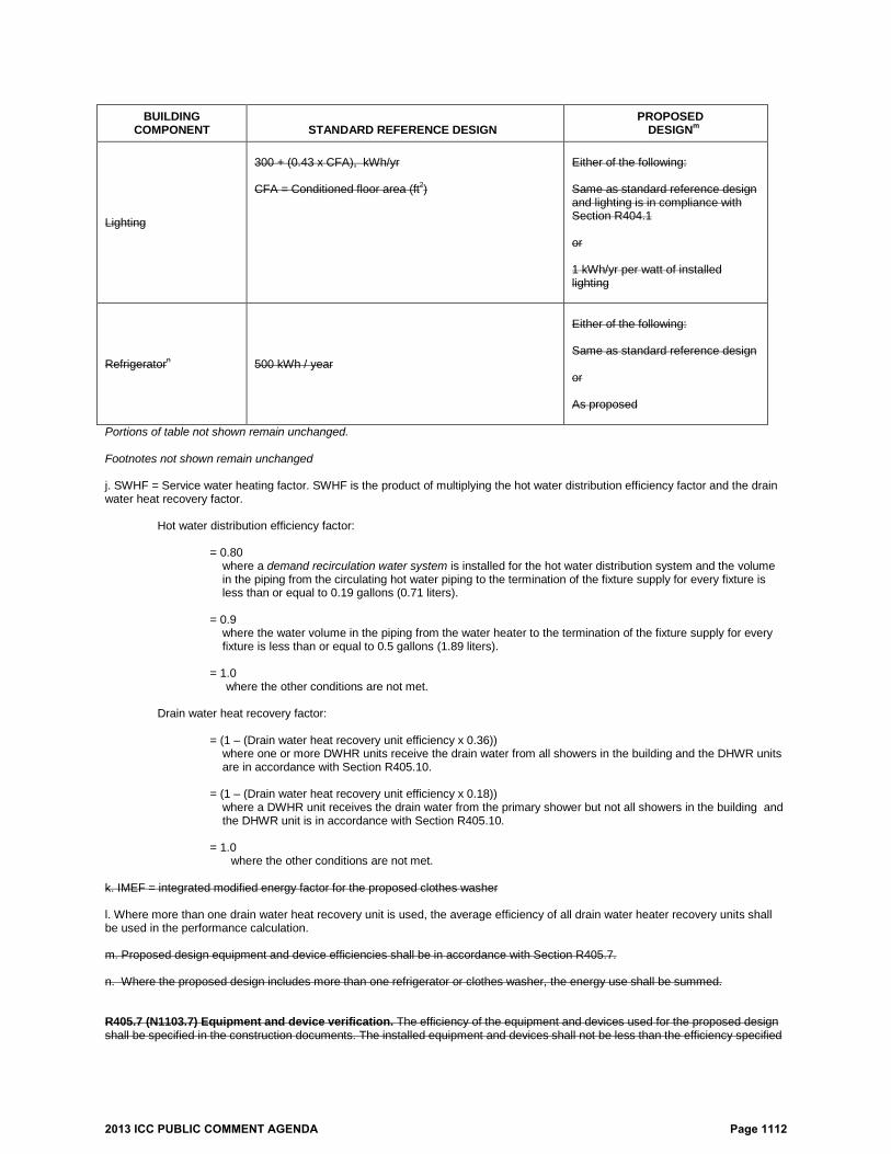
BUILDING COMPONENT
STANDARD REFERENCE DESIGN
PROPOSED DESIGNm
Lighting
300 + (0.43 x CFA), kWh/yr CFA = Conditioned floor area (ft2)
Either of the following: Same as standard reference design and lighting is in compliance with Section R404.1 or 1 kWh/yr per watt of installed lighting
Refrigeratorn
500 kWh / year
Either of the following: Same as standard reference design or As proposed
Portions of table not shown remain unchanged. Footnotes not shown remain unchanged j. SWHF = Service water heating factor. SWHF is the product of multiplying the hot water distribution efficiency factor and the drain water heat recovery factor.
Hot water distribution efficiency factor:
= 0.80 where a demand recirculation water system is installed for the hot water distribution system and the volume in the piping from the circulating hot water piping to the termination of the fixture supply for every fixture is less than or equal to 0.19 gallons (0.71 liters).
= 0.9
where the water volume in the piping from the water heater to the termination of the fixture supply for every fixture is less than or equal to 0.5 gallons (1.89 liters).
= 1.0
where the other conditions are not met. Drain water heat recovery factor:
= (1 – (Drain water heat recovery unit efficiency x 0.36)) where one or more DWHR units receive the drain water from all showers in the building and the DHWR units are in accordance with Section R405.10.
= (1 – (Drain water heat recovery unit efficiency x 0.18))
where a DWHR unit receives the drain water from the primary shower but not all showers in the building and the DHWR unit is in accordance with Section R405.10.
= 1.0
where the other conditions are not met. k. IMEF = integrated modified energy factor for the proposed clothes washer l. Where more than one drain water heat recovery unit is used, the average efficiency of all drain water heater recovery units shall be used in the performance calculation. m. Proposed design equipment and device efficiencies shall be in accordance with Section R405.7. n. Where the proposed design includes more than one refrigerator or clothes washer, the energy use shall be summed. R405.7 (N1103.7) Equipment and device verification. The efficiency of the equipment and devices used for the proposed design shall be specified in the construction documents. The installed equipment and devices shall not be less than the efficiency specified
2013 ICC PUBLIC COMMENT AGENDA Page 1112

in the construction documents. The efficiency of equipment and devices shall be indicated by the manufacturer on a label or on a specification sheet attached to the equipment or device. The equipment or device efficiency shall be readily observable for inspection after the equipment or device is installed. This section shall apply only to equipment and devices where the proposed design is different than the standard reference design for that equipment or device. R405.8 (N1103.8) Hot water distribution verification. The construction documents for the building shall show plumbing diagrams that indicate water heaters, plumbing fixtures, plumbing appliances, pipe sizes and layouts for hot water supply and hot water circulating system piping. The layouts shall indicate the volume of water in the branches of the piping from the nearest source of hot water piping to the termination of the fixture supply pipe. This section shall apply only where the proposed design for the hot water distribution system is different than the standard reference design for the hot water distribution system. R405.9 (N1103.9) Lighting verification. A schedule, by room, of lighting fixtures and lamps indicating the wattage of each fixture shall be provided for interior lighting and garage lighting. The sum of wattages on the schedule shall be used for the proposed design. This section shall apply only where the proposed design for lighting is different than the standard reference design for lighting. R405.10 (N1103.10) Drain water heat recovery units. Drain water heat recovery units shall be tested by the manufacturer for efficiency and pressure loss at a flow rate of 2.5 gpm (9.5 L/m) through each water side flow path. The water side pressure loss shall not exceed 3 psi (20.7 kPa) for each flow path. The manufacturer shall indicate the efficiency and pressure loss of the unit on a label or specification sheet attached to the unit. This section shall apply only where the efficiency of drain water heat recovery is used in the performance calculation. Commenters’ Reason: The Committee’s reasons were for the entire proposal. This comment addresses their concerns by limiting the changes to Service Water Heating. Water heating is one of the largest energy uses in new homes. The purpose of this comment is to enable builders who use the performance method to trade off the water heater equipment efficiency, hot water distribution system efficiency and the use of drain water heat recovery systems with other energy elements. Each of these measures are optional and non-mandatory.
The Committee approved a trade-off for water heater equipment efficiency in RE166. It is also included here to harmonize these credit(s). The two additional measures: “hot water distribution efficiency” and “drain water heat recovery” are both long long-lasting infrastructural components in homes, that are relatively simple to include during construction but often difficult to retrofit later.
Hot water distribution system efficiency is important because it limits the waste in delivering hot water to the point of water use. This does not limit hot water use, rather it limits hot water waste. Hot water must first flow through the pipes from the water heater to the point of use. Unless hot is water already in the pipes, the cooler water in the pipes must be emptied and replaced by hot water, which wastes water. After use the hot water left in the pipes cools down, unless there is another use within about an hour. The cool down is wasted heat. Thus hot water distribution routinely wastes both energy and water. Piping layouts with less water volume between the water heater and water use inherently waste less heat and less water. The two “distribution efficiency factors” and their savings for limiting wasted hot water are adapted for the IECC from the ANSI consensus standard ICC 700-2012 (National Green Building Standard). The factors, 0.90 and 0.80, represent a 10% and 20% savings respectively. As an additional benefit, limiting hot water waste means better performance, because the hot-water-user’s wait for the “cold water to get hot” is the time it takes to replace cool water in the pipes with hot water and smaller water volumes are replaced more quickly.
Drain water heat recovery (DWHR) works particularly well where heated water flows down the drain at the same time as water flows in that needs to be heated; this “coincident flow” occurs in homes with showering and lavatory use. Performance of a DWHR unit is characterized by both efficiency and pressure loss. Given the available DWHR efficiencies, savings are typically 10% to 35% of the energy used for heating water. To put the “0.36” in the equation in perspective, the “coincident flow” in a residence is typically 50%-70% of the hot water use, so 0.36 (36%) times the device’s efficiency is similar to saying the unit works well on showers and lavatories, and may also recover a portion of the rest of the hot water use in the home. The 0.36 also covers natural drain water heat loss and assumes the “worst-case” plumbing scenario for DWHR devices. This calculation of savings is conservative. Over 25,000 drain water heat recovery units have been installed in homes in Canada and the United States.
It is important to ensure that DWHR devices do not have high pressure loss in order to minimize the impact on water pressure in the home. Although Section 405.10 has been taken out of this proposal, the safe installation of DWHR is still covered. The Committee approved CE273 Part III, which provides reference standards that cover DWHR technology safety and performance. Public Comment 3: Edward R. Osann, Natural Resources Defense Council, representing self, requests Disapproval. Commenter’s Reason: While the concept of this proposal has merit, the "hot water distribution efficiency factor" used to score the performance of hot water distribution systems is essentially arbitrary. More objective measures of the energy impacts of various hot water distribution configurations are needed to avoid over- or under-crediting such measures relative to better documented energy-saving measures. RE172-13 Final Action: AS AM AMPC D
2013 ICC PUBLIC COMMENT AGENDA Page 1113

RE179-13 Table R405.5.2(1) (IRC Table N1105.5.2(1)), Table R405.5.2(3) (NEW) (IRC Table N1105.5.2(3) (NEW)), Chapter 5
Proposed Change as Submitted
Proponent: Neil Leslie, Gas Technology Institute representing self ([email protected]) Revise as follows:
Table R405.5.2(1) (N1105.5.2(1)) SPECIFICATION FOR THE STANDARD REFERENCE AND PROPOSED DESIGNS
BUILDING COMPONENT STANDARD REFERENCE DESIGN PROPOSED DESIGN
Heating systemsf , g
As proposed for other than electric heating without a heat pump. Where the proposed design utilizes electric heating without a heat pump the standard reference design shall be an air source heat pump meeting the requirements of Section R403 of the IECC—Commercial Provisions. Equipment type: in accordance with Table R405.5.2(3) Efficiency: in accordance wtih Table C403.2.3 (4) Capacity: sized in accordance with Section R403.6
As proposed
As proposed
Cooling systemsf, h ,g
As proposed Equipment type: in accordance Table R405.5.2(3) Efficiency: in accordance with Table C403.2.3(1) Capacity: sized in accordance with Section R403.6.
As proposed
As proposed
Service water heatingf,g,h,i
As proposed Use: same as proposed Equipment type: in accordance with Table R405.5.2(3) Efficiency: in accordance with Table C404.2 Capacity: same as proposed
As proposed
As proposed
gal/day=30 + (10 × Nbr)
Nbr = Number of bedrooms
(Portions of table not shown remain unchanged)
2013 ICC PUBLIC COMMENT AGENDA Page 1114

f. For a proposed design with multiple heating, cooling or water heating systems using different fuel types, the applicable standard reference design system capacities and fuel types shall be weighted in accordance with their respective loads as calculated by accepted engineering practice for each equipment and fuel type present. f g. For a proposed design without a proposed heating system, a heating system with the prevailing federal minimum efficiency shall be assumed for both the standard reference design and proposed design. g h. For a proposed design home without a proposed cooling system, an electric air conditioner with the prevailing federal minimum efficiency shall be assumed for both the standard reference design and the proposed design. i. For a proposed design with a nonstorage-type water heater, a 40-gallon storage-type water heater with the prevailing federal minimum energy factor for the same fuel as the predominant heating fuel type shall be assumed. For the case of a proposed design without a proposed water heater, a 40-gallon storage-type water heater with the prevailing federal minimum efficiency for the same fuel as the predominant heating fuel type shall be assumed for both the proposed design and standard reference design.
TABLE R405.5.2(3) (N1105.5.2(3)) EQUIPMENT MAP
SYSTEM EQUIPMENT TYPE
Heatinga Warm air furnaces, natural gas fired
Coolinga Air conditioners, air cooled
Service Water Heatinga Storage water heaters, natural gas a. Systems meeting current National Appliance Energy Conservation Act minimum efficiency requirements.
Add new standard to Chapter 5 as follows: DOE U.S Department of Energy c/o Superintendent of Documents U.S. Government Printing Office Washington, D.C 20402-9325 NAECA 87-(88) National Appliance Energy Conservation Act 1987 [Public Law 100-12 (with Amendments of 1988-P.L. 100-357)] Reason: The intent of the IECC is clearly defined.
“Intent. This code shall regulate the design and construction of buildings for the effective use and conservation of energy over the useful life of each building. This code is intended to provide flexibility to permit the use of innovative approaches and techniques to achieve this objective. This code is not intended to abridge safety, health or environmental requirements contained in other applicable codes or ordinances.”
Source: 2012 IECC. Sections C101.3 and R101.3. The code focus is “energy use… over the useful life of the building”. Buildings will perform to the requirements of this code for a long time. So the intent of the code focuses on “energy use” over the life of the building. Under the performance path, the IECC compares the energy use of a baseline building to the energy use of a proposed building.
This proposal addresses a lingering weakness in the code for those seeking to use innovative energy efficient systems. Simulations provide the means and methods to more fully understand, quantify and model actual energy use, whatever its form. This revision specifies a single standard reference design for heating, cooling, and service water heating systems, using technologies with low energy costs and high source energy efficiency as the baseline in each building component category. The revised text and tables:
• Establish a single baseline building performance requirement o for all service hot water (SHW) and HVAC systems o independent of making the system choice for the proposed building o at a realistic and achievable level using code-compliant technologies.
• Addresses the inconsistent mix of multiple prescriptive baseline building technology performance requirements in the current standard.
• Provides equitable and consistent treatment of all SHW and HVAC system options, including conventional, renewable energy, hybrid technology, and waste heat recovery options.
• Is indifferent to the SHW and HVAC system choice in the proposed building, comparing all SHW and HVAC system options against a single energy efficient baseline building energy cost or source energy performance requirement.
• Aligns the SHW and HVAC system performance requirement methodology with the envelope single baseline performance requirement methodology.
2013 ICC PUBLIC COMMENT AGENDA Page 1115
• Achieves the goal of reducing the site energy cost, consumption of primary energy resources, and global greenhouse gas emissions related to the operation of the building in a cost-effective and equitable manner.
A single technology-blind baseline performance requirement is the most technically defensible methodology for performance path calculations, and it is critical for equitable implementation of the IECC Performance Alternative requirements Section R405. Shifting to a single baseline design provides an equitable credit to all technologies that have lower annual energy costs or source energy consumption compared to the single baseline level irrespective of energy form or technology design.
The current code structure does not facilitate equitable comparison of mechanical systems based energy cost or source energy consumption.
IECC Section R405 currently uses multiple baseline mechanical system performance requirements. The mechanical systems are compared using multiple baselines by separating both categories of equipment and fuel types used within each equipment category. For example, the current code has 14 different baseline configurations across the five SHW system categories that may be relevant to the residential sector, none of which results in the same annual energy cost or source energy budget for performance path calculations. This mix of equivalencies is a counter-productive and inconsistent approach that can be mitigated by shifting to a single baseline building design for all proposed building design alternatives. The existing Section R405 also may be subject to various interpretations on the appropriate baseline design building for advanced multi-fuel appliance options, waste heat recovery options, or emerging technologies that reduce energy costs or source energy consumption significantly compared to options that currently qualify.
The baseline mechanical systems in the revised Table R405 use a single efficient baseline design for all proposed building configurations. The revised Table R405.5.2(1) and additional Table R405.5.2(3) apply a single baseline energy cost requirement consistently to any proposed mechanical system. The baseline does not prohibit any technology options. It correctly allows all options, including higher operating cost options, but considers their strong energy cost or source energy consumption disadvantages compared to the single baseline performance requirement. A designer who chooses a higher energy cost or source energy consumption option for the proposed building would only need to reduce the overall building energy cost or source energy consumption to the baseline level, and could do so through any combination of improved energy performance options, including HVAC, SHW, and envelope improvements.
The existing HVAC and SHW provisions are also inconsistent with standard reference baseline design criteria for envelope building components. Those building element provisions do not prescribe specific technology categories or subcategories, but are true performance based requirements (e.g., envelope requirements in overall U value) that give the designer maximum flexibility BEFORE making technology choices in the design. The designer is free to choose the most cost-effective envelope technology (fiberglass, polyurethane foam) to meet the single energy target for the building without arbitrary technology class prescriptive requirements for fiberglass or foam insulation. Unfortunately, the existing provisions of HVAC and SHW tables impose technology category and subcategory prescriptive requirements when using the performance path instead of true performance-based requirements. The impact is to establish the reference design building AFTER prescriptive technology category and energy design choices are made. This is an inequitable application of prescriptive requirements in the performance path. This constraint eliminates the credit for creative design choices that would significantly reduce energy cost, primary energy use, and greenhouse gas emissions.
The revised tables and text completely decouple the proposed building design choices from the standard reference design building’s energy cost or source energy performance requirement. The reference energy and technology choices in the revised section were selected to provide a practical and effective requirement to meet the intent of the standard while still offering appropriate incentives for the best available technologies based on their energy cost benefits. Encouraging rather than discouraging this design flexibility aligns closely with the IECC stated goal of reducing energy costs by 30 percent compared to the 2012 version. Cost Impact: The code change proposal will not increase the cost of construction.
R405.5.2(1)T-EC-LESLIE.DOC
Committee Action Hearing Results Committee Action: Disapproved Committee Reason: This proposal could have the possible effect of preemption of Federal Standards. Assembly Action: None
Individual Consideration Agenda
This item is on the agenda for individual consideration because public comments were submitted. Public Comment 1: Mark Krebs, Laclede Gas Company, representing self, requests Approval as Submitted. Commenter’s Reason: The committee’s decision to disapprove this critical proposal is not based on facts and is inconsistent with the stated intent of the IECC to provide “model code regulations that will result in the optimal utilization of fossil fuel and
2013 ICC PUBLIC COMMENT AGENDA Page 1116

nondepletable resources in all communities, large and small.” The current provisions treat various technology options as equivalent to each other even though there are demonstrable and meaningful differences in energy cost and source energy use among the fuel choice and technology options, especially for electric resistance and natural gas options. This results in suboptimal utilization of fossil fuels because significantly more coal and natural gas are burned in power plants to provide electricity for inefficient qualifying electric technologies than would be consumed by burning natural gas directly in the home using the more source energy efficient and lower energy cost gas technology. The current provisions result in meaningful fuel bias that the proposal fully corrects by changing to fuel blind, single baseline compliance provisions. The hearing committee erred in two significant ways in their stated rationale at the hearing and as reported in the summary of the hearing. The first error relates to the confusion about “lack of natural gas” in many areas of the country, and the resulting error by the committee rejecting the proposal as untenable for this reason. Natural gas availability is not the issue. Energy cost budget or source energy budget calculation is the correct issue for judging this proposal. Those metrics do not require natural gas availability in the proposed building for determining the compliance requirement. The necessary simulation for determination of the energy cost or source energy budget for the proposed home only requires that suitable natural gas cost or source energy information be available for use in the simulation. Natural gas cost information is already available and required by the IECC for other calculations in locations that have natural gas service availability. For locations that do not have natural gas service, a choice of local, state, provincial, or regional gas prices can easily be incorporated into the tool for determining the residential building’s energy cost budget. It is even easier to implement when using the source energy path because the IECC already includes the necessary conversion factors for all locations and situations. The proposal is simple to implement and easily applied to all residential buildings. The second error made by the committee is stated in the written summary as the only rationale for rejection: “This proposal could have the possible effect of preemption of Federal Standards.” That rationale is completely false. There is no prohibition against any appliance as a result of this proposal, thus there is no possible federal preemption effect. This proposal allows determination of an efficient, equitable energy cost budget (or source energy budget) at a level of performance using low energy cost and source energy efficient options to determine the baseline performance level. The proposal is fuel and technology agnostic, and is completely consistent with Federal Standard preemption provisions. If the disapproval relied on the stated rationale, the disapproval is dismissive and non-responsive to the proposal’s significant consumer and societal benefits. The most useful comparison illustrating the inherent flaw in the IECC methodology is a minimally compliant electric storage water heater compared to a minimally compliant gas storage water heater. Homes using NAECA minimum efficiency electric resistance storage water heating qualify equally as a NAECA minimum gas storage water heater, even though both the annual energy costs and primary energy consumption are much higher for the resistance water heater than for the gas water heater (typically twice as high). Based on a typical home in Laclede’s service territory, annual energy use for an NAECA minimum electric resistance water heater is 3,920 kWH, while a NAECA minimum gas water heater uses 205 therms. Using average Missouri energy rates available from EIA of $0.098 per kWh and $1.05 per therm, the electric water heater annual cost of operation is $384, while the natural gas water heater costs only $215 per year, a 79% increase in the energy cost budget for the electric water heater. Using the respective source energy conversion factors of 3.16 and 1.1 in the IECC, the source energy consumption of the electric water heater is 42.3 MBtu while the source energy consumption for the gas water heater is only 22.6 MBtu, an 87% increase in the source energy budget for the electric water heater. IECC considers them equal for compliance purposes because it uses a separate, biased reference home for determining compliance for electric water heating systems. The higher energy cost and source energy represent harmful costs to the consumers and society. It is this “best efforts” harmful bias that the proposed shift to a single baseline system methodology fully corrects. ASHRAE Standard 90.1-2013 will include a new single baseline system methodology in the performance path for all new commercial buildings. This methodology is identical to the single baseline mechanical system methodology proposed in RE179. The 90.1 single baseline tables are more sophisticated than those in RE179 to accommodate the wide variety of building types and regional building practices in the commercial sector. By including the proposed methodology in the residential provisions of the 2014 IECC, the residential and commercial provisions will be internally consistent. Public Comment 2: Neil Leslie, Gas Technology Institute representing self, requests Approval as Modified by this Public Comment. Modify the proposal as follows:
Table R405.5.2(1) SPECIFICATION FOR THE STANDARD REFERENCE AND PROPOSED DESIGNS
BUILDING COMPONENT STANDARD REFERENCE DESIGN PROPOSED DESIGN
Heating systemsf Efficiency: from Table C403.2.3(4) C403.2.3 (2)
Cooling systemsg Efficiency: from Table C403.2.3(1) C403.2.3(2)
Table R405.5.2(3) EQUIPMENT MAP
SYSTEMa EQUIPMENT TYPE
2013 ICC PUBLIC COMMENT AGENDA Page 1117

Heatinga Warm air furnaces, natural gas fired Air cooled (heating mode)
Coolinga Air conditioners, air cooled (cooling mode)
Service Water Heatinga Storage wWater heaters, natural gas electric, Resistance Subcategory
Commenter’s Reason: The amendment to the single baseline system proposal in RE179-13 is intended to address the specific concerns expressed at the hearing and in the rationale for disapproval. By shifting to electric technologies for all baseline systems, there is no longer an issue (real or perceived) with fuel choice availability. Electric technologies are considered always available as long as electricity is provided to the home, either through the grid or through on site power generation. The amendment also provides another way to allay fears about Federal Standard preemption. There is no prohibition against any appliance as a result of either the original proposal or this amendment, thus there is no possible federal preemption effect. However, this amendment allows determination of an equitable energy cost budget (or source energy budget) at a level of performance using compliant electric technology options with relatively more permissive energy cost and source energy budgets to determine the baseline performance level. The proposal and this amendment both are fuel and technology agnostic, and both are completely consistent with Federal Standard preemption provisions. The key difference between the original proposal and this amendment is the choice between rewarding better performance or penalizing worse performance. The original proposal rewards exceptional performance while penalizing poorer performance relative to the more stringent energy cost and source energy budgets when using the natural gas baseline systems. In this amendment, appliance options such as natural gas heating and water heating systems that improve the energy performance of the home (i.e., lower energy cost or source energy consumption), are rewarded compared to the fully compliant baseline electric heat pump and resistance water heating systems. Tradeoffs based on the energy cost or source energy budget add flexibility to the design options and are more lenient than the original proposal. At the same time, options that are currently compliant under the separate, biased baseline budget methodology are not penalized because they are the baseline systems in this amendment. With either the original proposal or this amendment, the IECC has already chosen the right metrics for energy performance, with the choice of energy cost budget (for adopting authorities mainly concerned about the homeowner’s economic objectives), or source energy budget (for adopting authorities mainly concerned about the homeowner’s energy consumption impacts on primary energy consumption). The proposal provides the critical single baseline budget methodology to implement these metrics correctly. It is only by implementing the correct metrics correctly through the single baseline methodology that the IECC can avoid adverse effects and unintended consequences on users of the standard. There is another development in 2013 that corroborates the proposal and a shift to an equitable single baseline methodology for consistency. ASHRAE Standard 90.1-2013 (a deemed to comply option in IECC-2014) will include for the first time a new single baseline system methodology in the performance path for all new commercial buildings. This methodology is identical to the single baseline mechanical system methodology proposed in RE179. The 90.1 single baseline tables are more sophisticated than those in RE179 to accommodate the wide variety of building types and regional building practices in the commercial sector. By including the proposed methodology in the residential provisions of the 2014 IECC, the residential and commercial provisions will be internally consistent. RE179-13 Final Action: AS AM AMPC D
2013 ICC PUBLIC COMMENT AGENDA Page 1118

RE181-13 Table R405.5.2(1) (IRC N1105.5.2(1))
Proposed Change as Submitted Proponent: Jeff Sonne, Florida Solar Energy Center representing the Florida Solar Energy Center ([email protected]) Revise as follows:
TABLE R405.5.2(1) (N1105.5.2(1)) SPECIFICATIONS FOR THE STANDARD REFERENCE AND PROPOSED DESIGNS
BUILDING COMPONENT STANDARD REFERENCE DESIGN PROPOSED
DESIGN
Glazinga
Total areab = (a) The proposed glazing area; where proposed glazing area is less than 15% of the conditioned floor area. (b) 15% of the conditioned floor area; where the proposed glazing area is 15% or more of the conditioned floor area.
As proposed
Orientation: equally distributed to four cardinal compass orientations (N, E, S & W).
As proposed
U-factor: from Table R402.1.3 As proposed SHGC: From Table R402.1.1 except that for climates with no requirement (NR) SHGC = 0.40 shall be used. Interior shade fraction: 0.92-(0.21 × SHGC for the standard reference design)
Summer: 0.70 Winter: 0.85
External shading: none
As proposed 0.92-(0.21 × SHGC as proposed) Same as Standard Reference Design Same as Standard Reference Design
As proposed
(Portions of Table not shown remain unchanged) Reason: Glazing Area Glazed areas are the least efficient and most costly components of homes. Even the best windows and glass doors admit much more solar heat gain than walls, roofs and floors. And even the best windows and doors have thermal conductances that are far inferior to walls, roofs and floors.
Table 1 below presents the 2012 IECC requirements for envelope components in IECC climate zone 2. While there are no IECC requirements for the SHGC of opaque envelope components like walls, ceilings and floors, an equivalent SHGC can be calculated using the component U-Factor, a reasonable sol-air temperature, a reasonable interior temperature (75 oF) and a reasonable incident solar radiation, as follows:
SHGCequiv = U-Factor*(Tsol-air - Tint) / (SolarIncident) For Table 1, the assumed sol-air temperatures were 140 oF for walls and 160 oF for roofs (ceilings) and the assumed incident solar radiation was 250 Btu/h for walls and 300 Btu/h for roofs (ceilings). Floors receive no solar radiation and thus do not experience heat gains due to
2013 ICC PUBLIC COMMENT AGENDA Page 1119

direct solar radiation as do fenestration, walls and roofs (ceilings).
Table 1. Envelope Component Efficacies Envelope Component
IECC* U-Factor
U-Factor Ratio
IECC* SHGC
SHGC Ratio
Fenestration 0.400 1.00 0.250 1.00 Frame walls 0.082 4.88 0.021** 11.73 Mass walls 0.165 2.42 0.043** 5.83 Ceilings 0.030 13.33 0.009** 29.41 Floors 0.064 6.25 0.000** ∞ * IECC U-Factor and SHGC values for Climate Zone 2 ** Computed estimate
The U-Factor and SHGC ratios in Table 1 compare the heat retardation efficacy of each of the other envelope components to the heat retardation efficacy of fenestrations. These ratios show that the opaque envelope components are 2.42 to 13.33 times as efficacious in retarding heat flow by conductance as fenestrations and 5.83 to 29.41 times as efficacious in retarding solar heat gains as fenestrations.
Per unit area, fenestrations are also the most expensive envelope components in new homes. Estimates from the 2011 R.S. Means Residential Cost Data show typical code compliant concrete block wall construction prices to be about $15/ft2 while typical code compliant window prices are somewhat more than double this amount, at about $32/ft2.
The data show that fenestrations are relatively costly home amenities, which are not particularly energy efficient compared with other envelope components. The principle function of fenestration is to visually bring the outdoors into the comfort conditioned interior living space. Thus, cost is the principle determinant of fenestration area as a percentage of conditioned floor area, with larger fenestration percentages much more likely in high-end, expensive homes than in low-end, smaller homes.
Reductions in glazing area improve the energy performance of homes. If homes are evaluated on an energy performance basis then, all other things being equal, the home with the smaller window area will have less energy consumption. That being the case, a simulated performance alternative should recognize this smaller energy consumption rather than adjust the Standard Reference Design glazing area such that this smaller energy use is effectively disallowed as an energy performance characteristic of the home.
Most homes that choose smaller fenestration area are small, low-cost homes. Thus, the choice to incorporate less fenestration area is an economic decision – made to reduce the cost of the home. The fact that these homes are smaller than the typical new home also significantly reduces the energy use of the home compared to the more typical larger new home. As a result, this “sliding” glazing area in the 2012 IECC Standard Reference Design actually requires the smaller, low-cost home with less window area to meet a higher energy performance standard than the larger more energy intensive typical home. This constitutes a strong affirmation of the old saw that “no good deed shall go unpunished.” For reasons of cost effectiveness and the equitable treatment of smaller, low-cost homes, the Code should set a single standard for glazing area in the Standard Reference Design and not allow it to “float down” with the window area of the Proposed Design. Interior Shading Coefficient The 2012 IECC modifies the interior shading coefficient of fenestrations as a function of the SHGC of the fenestration. It does this in both the Standard Reference Design and the Proposed Design. The equation for the 2012 IECC interior shading coefficient is as follows:
Interior Shade = 0.92 * (0.21*SHGC) Compared with the 2009 IECC interior shading coefficients, which were not dependent on the SHGC of the fenestration but were based on the likely behavior of the home occupants, this equation effectively penalizes high performance windows in climates like Florida where lower SHGCs are desirable. The equation shows that the better the SHGC (lower is better in Florida), the lower the interior shading coefficient. Thus, a window with a SHGC of 0.5 would have an interior shading coefficient of 0.82 while a window with a SHGC of 0.2 would have an interior shading coefficient of 0.88. This results in the poorer performing window getting more energy performance credit from interior shading than the better performing window.
Table 2 examines how the change from the 2009 IECC interior shading coefficients to the 2012 IECC interior shading coefficients impact projected performance. A 2-story, 2400 ft2, slab-on-grade frame wall IECC 2012 Standard Reference Design home is used for both sets of simulations. The only change is the manner in which interior shading is treated. The values in the table are the annual kWh for heating and cooling in the cities specified.
Table 2. H&C Interior Shading Example Condition Miami Orlando Tally
IECC 2009 4981 3507 3426 IECC 2012 5237 3685 3579 kWh change 256 178 153 % change 5.1% 5.1% 4.5%
Table 2 shows that these high performance (SHGC-0.25) windows show 4.5% - 5.1% greater energy use for the IECC 2012 interior shading coefficient specification than for the 2009 IECC interior shading coefficient specification. This means that these high-performance windows will achieve less energy performance credit using the 2012 IECC specification that they do using the 2009 IECC specification. Surely this was not the intent of the 2012 change to the IECC interior shading coefficient.
2013 ICC PUBLIC COMMENT AGENDA Page 1120

In addition to the performance differences shown in Table 2, the 2012 IECC interior shading coefficients also do not reflect the likely behavior of the occupants. Occupants are more likely to use shades and blinds principally for privacy reasons but are also likely to use somewhat more shades and blinds during the air conditioning season to keep the sun out of the living space and use somewhat less shades and blinds during the heating season to let the sun into the living space. This occupant behavior is reflected in the 2009 IECC interior shading coefficient specification but abandoned for unknown reasons in the 2012 IECC interior shading coefficient specification.
Based on this analysis, the proponent recommends that the IECC set a single, non-floating window area to conditioned floor area ratio of 15% for the Standard Reference Design and that the IECC 2009 specification for interior shading coefficient be maintained for both the Standard Reference Design and the Proposed Design. Cost Impact: The code change proposal will not increase the cost of construction.
R405.5.2(1)T-EC-SONNE.DOC
Committee Action Hearing Results Committee Action: Disapproved Committee Reason: Consistent with action taken on RE181-13. Assembly Action: None
Individual Consideration Agenda
This item is on the agenda for individual consideration because a public comment was submitted. Public Comment: Jeff Sonne representing Florida Solar Energy Center, requests Approval as Submitted. Commenter’s Reason: Proposal RE164-13 was approved as submitted. We have submitted a separate comment recommending that RE164-13 be disapproved, and repeat the comment here in support of alternative proposal RE181-13. RE164-13 is inconsistent with the direction taken by all other programs having reference homes. DOE’s Builder’s Challenge program and EPA’s EnergyStar program take exception with IECC and limit the percent glass of the reference home so that homes that use more energy due to large window areas have to make it up. It is difficult to consider the IECC as a serious energy code with unlimited glass areas receiving no penalty. In our experience it is large homes that tend to have 25% to 40% glass-to-floor area, requiring substantially more heating and air conditioning. Windows are better than they used to be, but they are a weak component in the building envelope. The agreement made in 2003 was erroneous. The prescriptive method should also have a window area limitation forcing the UA or performance method. Please don’t make the code worse, reject RE164-13. We still stand behind RE181-13 as an appropriate solution. RE181-13 Final Action: AS AM AMPC D
2013 ICC PUBLIC COMMENT AGENDA Page 1121

RE186-13 R202 (IRC N1101.9), R401.2 (IRC N1101.15), R406 (NEW) (IRC N1106 (NEW))
Proposed Change as Submitted Proponent: William Fay, Energy Efficient Codes Coalition; Brian Dean, Energy Efficient Codes Coalition; Garrett Stone, Brickfield Burchette Ritts & Stone, PC; Jeff Harris, Alliance to Save Energy; Harry Misuriello, American Council for an Energy-Efficient Economy; and Bill Prindle, Energy Efficient Codes Coalition Revise follows:
SECTION R401 (N1101) GENERAL
R401.2 (IRC N1101.15)Compliance. Projects shall comply with Sections identified as "mandatory" and with either sections identified as "prescriptive" or the simulated performance alternative approach in Section R405. In addition, all projects shall comply with Section R406.
SECTION R406 (N1106) ADDITIONAL ENERGY EFFICIENCY (MANDATORY)
R406.1 (N1106.1)Scope. This section establishes additional mandatory requirements applicable to all compliance approaches to achieve additional energy efficiency.
R406.2 (N1106.2)Points-based compliance. One or more energy efficiency measure(s) shall be installed in accordance with Section R406.3 that cumulatively equal or exceed 5 (five) Flex Points for the appropriate Climate Zone. Projects complying under the simulated performance alternative outlined in Section R405 shall demonstrate compliance with Section R405 without including in the proposed design any features that will be utilized to comply with Section R406.
Exceptions: The requirements of this section shall not apply to:
1. Projects complying under the performance approach outlined in Section R405, where the proposed design under section R405.3 is shown to have an annual energy cost that is less than or equal to 95% of the annual energy cost of the standard reference design.
2. Projects with an on-site or building integrated renewable energy system installed that provides not less than 0.50 watts per square foot (5.4 W/m2) of conditioned floor area.
3. Additions with a conditioned floor area equal to or less than 1,000 square feet. 4. Alterations, renovations and repairs to an existing building.
R406.3 (N1106.3) Flex Points for additional energy efficiency. Measures shall be selected from the applicable Flex Points Table based on the applicable federal minimum equipment efficiency established by federal rule for that state that applies to the specified heating and cooling equipment on the date that a permit is issued. Each measure chosen shall receive credit for the Flex Points as indicated in the applicable Table for the specific Climate Zone. Interpolation of points between measures shall not be permitted.
R406.3.1 (N1106.3.1) Use of Flex Points Table R406.3.1. In states where the applicable federal minimum efficiencies are less than or equal to 80 AFUE for non-weatherized gas residential furnaces, equal to 7.7 HSPF for split system heat pumps, and equal to 13 SEER for split system air conditioners, Table R406.3.1 shall be used.
TABLE R406.3.1 (N1106.3.1)
FLEX POINTS FOR ADDITIONAL ENERGY EFFICIENCY Measure Measure Description Flex Point Value
2013 ICC PUBLIC COMMENT AGENDA Page 1122

Number CZ 1
CZ 2
CZ 3
CZ 4
CZ 4C
a
CZ 5
CZ 6
CZ 7
CZ 8
1a ≥ 2.5% reduction in total UA b 2 2 2 2 2 2 3 4 4 1b ≥ 5% reduction in total UA b 3 3 3 3 3 4 5 5 5 1c ≥ 7.5% reduction in total UA b 5 5 5 5 5 6 7 8 8 1d ≥ 10% reduction in total UA b 6 7 7 7 8 8 9 10 10
2a ≥ 10% reduction in glazed fenestration area-weighted average SHGC 2 1 - - - - - - -
2b ≥ 20% reduction in glazed fenestration area-weighted average SHGC 4 1 - - - - - - -
3a ≤ 4 ACH50 air leakage rate with ERV or HRV installed c 1 2 - - - - - - -
3b ≤ 3 ACH50 air leakage rate with ERV or HRV installed c 2 4 5 6 7 7 7 8 8
3c ≤ 2 ACH50 air leakage rate with ERV or HRV installed c 2 5 7 9 9 9 10 11 11
4a
≤ 2 CFM of total duct leakage per 100 square feet of conditioned floor area when tested in accordance with Section R403.2.2
1 1 1 1 - 1 1 1 1
4b 100% of duct thermal distribution system located in passively conditioned space and/or actively conditioned space
1 1 1 1 1 1 2 2 2
4c 100% of duct thermal distribution system located in actively conditioned space d
8 8 9 11 8 12 15 17 17
4d
100% of ductless thermal distribution system located in passively conditioned space and/or actively conditioned space d
8 8 9 11 8 12 15 17 17
4e 100% of hydronic thermal distribution system located in actively conditioned space d
8 8 9 11 8 12 15 17 17
5a ≥ 15 SEER and ≥ 12.5 EER cooling system efficiency e 4 3 1 1 - - - - -
5b ≥ 16 SEER and ≥ 13 EER cooling system efficiency e 7 5 2 1 - - - - -
5c ≥ 18 SEER and ≥ 14 EER cooling system efficiency e 11 8 3 2 - 1 - - -
5d ≥ 16 EER cooling system efficiency e 11 8 3 2 - 1 - - - 5e ≥ 18 EER cooling system efficiency e 15 11 4 3 - 1 - - - 5f ≥ 20 EER cooling system efficiency e 17 13 5 3 - 1 1 - - 6a ≥ 90 AFUE heating system efficiency f - 1 4 6 6 7 7 8 9 6b ≥ 92 AFUE heating system efficiency f - 2 5 7 7 8 9 10 11 6c ≥ 95 AFUE heating system efficiency f - 2 6 8 9 10 11 12 13 6d ≥ 96 AFUE heating system efficiency f - 2 6 9 10 10 11 12 14 6e ≥ 98 AFUE heating system efficiency f - 3 7 10 11 12 13 14 15 7a ≥ 8.8 HSPF heating system efficiency f - - 1 1 2 2 2 2 1 7b ≥ 9.5 HSPF heating system efficiency f - 1 2 3 3 4 4 4 3 7c ≥ 10.5 HSPF heating system efficiency f - 1 3 6 6 7 6 5 5
2013 ICC PUBLIC COMMENT AGENDA Page 1123

7d ≥ 3 COP heating system efficiency f - 1 3 5 5 6 5 5 4 7e ≥ 3.5 COP heating system efficiency f - 2 5 8 8 9 9 9 7 7f ≥ 4 COP heating system efficiency f - 3 6 10 10 12 11 10 8
8a ≥ 0.7 EF for fossil fuel service water heating system - - - - - - - - -
8b ≥ 0.8 EF for fossil fuel service water heating system 4 3 3 2 2 2 1 1 1
8c ≥ 0.95 EF for electric service water heating system - - - - - - - - -
8d ≥ 1.15 EF for electric service water heating system 7 7 7 4 5 3 3 2 1
8e ≥ 0.4 Solar Fraction for service water heating system 6 7 9 7 9 6 5 4 3
a. Climate Zone 4C is Climate Zone Marine 4. b. The Total UA shall be calculated in accordance with Section R402.1.4 Total UA alternative. c. Minimum Heat Recovery Ventilator (HRV) and Energy Recovery Ventilator (ERV) requirements, measured at the lowest tested net supply airflow, shall be ≥ 75% Sensible Recovery Efficiency (SRE), ≤ 1.1 W/CFM Fan Energy and shall not use recirculation as a defrost strategy. In addition, the Energy Recovery Ventilator (ERV) shall be ≥ 50% Latent Recovery/Moisture Transfer (LRMT). d. To achieve 100% of the thermal distribution located in the actively conditioned space, no ducts or pipes used for the heating and cooling systems shall be located within walls or ceilings where losses are not directly regained into the conditioned space. e. For multiple cooling systems, all systems shall meet or exceed the minimum efficiency requirements in Table R406.3.1 and shall be sized to serve 100% of the cooling design load. As an alternative, each system installed shall receive credit for the percentage of the Flex Points for the measure equal to the percentage of the cooling design load served by the system. f. For multiple heating systems, all systems shall meet or exceed the minimum efficiency requirements in Table R406.3.1 and shall be sized to serve 100% of the heating design load. As an alternative, each system installed shall receive credit for the percentage of the Flex Points for the measure equal to the percentage of the heating design load served by the system.
R406.3.2 (N1106.3.2) Use of Flex Points Table R406.3.2.. In states where the applicable federal minimum efficiencies are less than or equal to 80 AFUE for non-weatherized gas residential furnaces, equal to 8.2 HSPF for split system heat pumps, and less than or equal to 14 SEER for split system air conditioners, Table R406.3.2 shall be used.
TABLE R406.3.2 (N1106.3.2)
FLEX POINTS FOR ADDITIONAL ENERGY EFFICIENCY
Measure Number Measure Description
Flex Point Value
CZ 1
CZ 2
CZ 3
CZ 4
CZ 4C
a
CZ 5
CZ 6
CZ 7
CZ 8
1a ≥ 2.5% reduction in total UA b 1 1 2 2 2 2 3 4 4 1b ≥ 5% reduction in total UA b 3 3 3 3 3 4 5 5 5 1c ≥ 7.5% reduction in total UA b 5 5 5 5 5 6 7 8 8 1d ≥ 10% reduction in total UA b 6 7 7 7 8 8 9 10 10
2a ≥ 10% reduction in glazed fenestration area-weighted average SHGC 2 1 - - - - - - -
2b ≥ 20% reduction in glazed fenestration area-weighted average SHGC 4 1 - - - - - - -
3a ≤ 4 ACH50 air leakage rate with ERV or HRV installed c 1 2 - - - - - - -
3b ≤ 3 ACH50 air leakage rate with ERV or HRV installed c 2 4 5 7 7 7 7 8 8
3c ≤ 2 ACH50 air leakage rate with ERV or HRV installed c 2 5 7 9 9 9 10 11 11
2013 ICC PUBLIC COMMENT AGENDA Page 1124

4a
≤ 2 CFM of total duct leakage per 100 square feet of conditioned floor area when tested in accordance with Section R403.2.2
1 1 1 1 - 1 1 1 1
4b 100% of duct thermal distribution system located in passively conditioned space and/or actively conditioned space
1 1 1 1 1 1 2 2 2
4c 100% of duct thermal distribution system located in actively conditioned space d 8 8 9 11 8 12 15 17 17
4d 100% of ductless thermal distribution system located in passively conditioned space and/or actively conditioned space d
8 8 9 11 8 12 15 17 17
4e 100% of hydronic thermal distribution system located in actively conditioned space d
8 8 9 11 8 12 15 17 17
5a ≥ 15 SEER and ≥ 12.5 EER cooling system efficiency e 2 2 1 - - - - - -
5b ≥ 16 SEER and ≥ 13 EER cooling system efficiency e 5 4 1 1 - - - - -
5c ≥ 18 SEER and ≥ 14 EER cooling system efficiency e 9 7 3 2 - - - - -
5d ≥ 16 EER cooling system efficiency e 10 7 3 2 - - - - - 5e ≥ 18 EER cooling system efficiency e 13 10 4 2 - 1 - - - 5f ≥ 20 EER cooling system efficiency e 16 12 5 3 - 1 - - - 6a ≥ 90 AFUE heating system efficiency f - 2 4 6 6 7 8 8 9 6b ≥ 92 AFUE heating system efficiency f - 2 5 7 7 8 9 10 11 6c ≥ 95 AFUE heating system efficiency f - 2 6 8 9 10 11 12 13 6d ≥ 96 AFUE heating system efficiency f - 2 6 9 10 10 11 12 14 6e ≥ 98 AFUE heating system efficiency f - 3 7 10 11 12 13 14 15 7a ≥ 8.8 HSPF heating system efficiency f - - - - - - - - - 7b ≥ 9.5 HSPF heating system efficiency f - - 1 2 2 2 2 2 1 7c ≥ 10.5 HSPF heating system efficiency f - 1 2 4 4 5 4 3 3 7d ≥ 3 COP heating system efficiency f - 1 2 3 3 4 3 3 2 7e ≥ 3.5 COP heating system efficiency f - 2 4 6 6 8 7 6 5 7f ≥ 4 COP heating system efficiency f - 2 5 8 9 10 10 9 7
8a ≥ 0.7 EF for fossil fuel service water heating system 2 2 - - - - - - -
8b ≥ 0.8 EF for fossil fuel service water heating system 7 5 4 3 2 2 2 1 1
8c ≥ 0.95 EF for electric service water heating system - - - - - - - - -
8d ≥ 1.15 EF for electric service water heating system 7 7 7 4 5 3 3 2 2
8e ≥ 0.4 Solar Fraction for service water heating system 8 9 9 7 9 6 5 4 3
a. Climate Zone 4C is Climate Zone Marine 4. b. The Total UA shall be calculated in accordance with Section R402.1.4 Total UA alternative. c. Minimum Heat Recovery Ventilator (HRV) and Energy Recovery Ventilator (ERV) requirements, measured at the lowest tested net supply airflow, shall be ≥ 75% Sensible Recovery Efficiency (SRE), ≤ 1.1 W/CFM Fan Energy and shall not use recirculation as a defrost strategy. In addition, the Energy Recovery Ventilator (ERV) shall be ≥ 50% Latent Recovery/Moisture Transfer (LRMT).
2013 ICC PUBLIC COMMENT AGENDA Page 1125

d. To achieve 100% of the thermal distribution located in the actively conditioned space, no ducts or pipes used for the heating and cooling systems shall be located within walls or ceilings where losses are not directly regained into the conditioned space. e. For multiple cooling systems, all systems shall meet or exceed the minimum efficiency requirements in Table R406.3.2 and shall be sized to serve 100% of the cooling design load. As an alternative, each system installed shall receive credit for the percentage of the Flex Points for the measure equal to the percentage of the cooling design load served by the system. f. For multiple heating systems, all systems shall meet or exceed the minimum efficiency requirements in Table R406.3.2 and shall be sized to serve 100% of the heating design load. As an alternative, each system installed shall receive credit for the percentage of the Flex Points for the measure equal to the percentage of the heating design load served by the system.
R406.3.3 (N1106.3.3) Use of Flex Points Table R406.3.3. In states where the applicable federal minimum efficiencies are equal to 90 AFUE for non-weatherized gas residential furnaces, equal to 8.2 HSPF for split system heat pumps, and less than or equal to 14 SEER for split system air conditioners, Table R406.3.3 shall be used.
TABLE R406.3.3 (N1106.3.3)
FLEX POINTS FOR ADDITIONAL ENERGY EFFICIENCY
Measure Number Measure Description
Flex Point Value
CZ 1
CZ 2
CZ 3
CZ 4
CZ 4C
a
CZ 5
CZ 6
CZ 7
CZ 8
1a ≥ 2.5% reduction in total UA b 1 1 2 2 2 2 3 4 4 1b ≥ 5% reduction in total UA b 3 3 3 3 3 4 4 5 5 1c ≥ 7.5% reduction in total UA b 4 5 5 5 5 6 7 8 8 1d ≥ 10% reduction in total UA b 6 7 7 7 7 8 9 10 10
2a ≥ 10% reduction in glazed fenestration area-weighted average SHGC 2 1 - - - - - - -
2b ≥ 20% reduction in glazed fenestration area-weighted average SHGC 4 2 - - - - - - -
3a ≤ 4 ACH50 air leakage rate with ERV or HRV installed c 1 2 - - - - - - -
3b ≤ 3 ACH50 air leakage rate with ERV or HRV installed c 2 4 5 6 7 7 7 8 8
3c ≤ 2 ACH50 air leakage rate with ERV or HRV installed c 2 5 7 9 9 9 10 11 11
4a ≤ 2 CFM of total duct leakage per 100 square feet of conditioned floor area when tested in accordance with Section R403.2.2
1 1 1 1 - 1 1 1 1
4b 100% of duct thermal distribution system located in passively conditioned space and/or actively conditioned space
1 1 1 1 1 1 2 2 2
4c 100% of duct thermal distribution system located in actively conditioned space d 8 8 9 10 8 12 15 17 17
4d 100% of ductless thermal distribution system located in passively conditioned space and/or actively conditioned space d
8 8 9 10 8 12 15 17 17
4e 100% of hydronic thermal distribution system located in actively conditioned space d
8 8 9 10 8 12 15 17 17
5a ≥ 15 SEER and ≥ 12.5 EER cooling system efficiency e 2 2 1 - - - - - -
5b ≥ 16 SEER and ≥ 13 EER cooling system efficiency e 5 4 1 1 - - - - -
5c ≥ 18 SEER and ≥ 14 EER cooling system 9 7 3 2 - - - - -
2013 ICC PUBLIC COMMENT AGENDA Page 1126

efficiency e
5d ≥ 16 EER cooling system efficiency e 10 7 3 2 - - - - - 5e ≥ 18 EER cooling system efficiency e 13 10 4 2 - 1 - - - 5f ≥ 20 EER cooling system efficiency e 16 12 5 3 - 1 - - - 6a ≥ 90 AFUE heating system efficiency f - - - - - - - - - 6b ≥ 92 AFUE heating system efficiency f - - - 1 1 1 1 1 1 6c ≥ 95 AFUE heating system efficiency f - - 2 2 3 3 3 4 4 6d ≥ 96 AFUE heating system efficiency f - 1 2 3 3 4 4 4 5 6e ≥ 98 AFUE heating system efficiency f - 1 3 4 4 5 5 6 6 7a ≥ 8.8 HSPF heating system efficiency f - - - - - - - - - 7b ≥ 9.5 HSPF heating system efficiency f - - 1 2 2 2 2 2 1 7c ≥ 10.5 HSPF heating system efficiency f - 1 2 4 4 5 4 3 3 7d ≥ 3 COP heating system efficiency f - 1 2 3 3 4 3 3 2 7e ≥ 3.5 COP heating system efficiency f - 2 4 6 6 8 7 6 5 7f ≥ 4 COP heating system efficiency f - 2 5 8 9 10 10 9 7
8a ≥ 0.7 EF for fossil fuel service water heating system 2 2 1 - - - - - -
8b ≥ 0.8 EF for fossil fuel service water heating system 7 5 4 3 2 2 2 1 1
8c ≥ 0.95 EF for electric service water heating system - - - - - - - - -
8d ≥ 1.15 EF for electric service water heating system 7 7 7 4 5 3 3 2 1
8e ≥ 0.4 Solar Fraction for service water heating system 8 9 9 7 9 6 5 4 3
a. Climate Zone 4C is Climate Zone Marine 4. b. The Total UA shall be calculated in accordance with Section R402.1.4 Total UA alternative. c. Minimum Heat Recovery Ventilator (HRV) and Energy Recovery Ventilator (ERV) requirements, measured at the lowest tested net supply airflow, shall be ≥ 75% Sensible Recovery Efficiency (SRE), ≤ 1.1 W/CFM Fan Energy and shall not use recirculation as a defrost strategy. In addition, the Energy Recovery Ventilator (ERV) shall be ≥ 50% Latent Recovery/Moisture Transfer (LRMT). d. To achieve 100% of the thermal distribution located in the actively conditioned space, no ducts or pipes used for the heating and cooling systems shall be located within walls or ceilings where losses are not directly regained into the conditioned space. e. For multiple cooling systems, all systems shall meet or exceed the minimum efficiency requirements in Table R406.3.3 and shall be sized to serve 100% of the cooling design load. As an alternative, each system installed shall receive credit for the percentage of the Flex Points for the measure equal to the percentage of the cooling design load served by the system. f. For multiple heating systems, all systems shall meet or exceed the minimum efficiency requirements in Table R406.3.3 and shall be sized to serve 100% of the heating design load. As an alternative, each system installed shall receive credit for the percentage of the Flex Points for the measure equal to the percentage of the heating design load served by the system.
Revise as follows:
SECTION R202 (IRC N1101.9) GENERAL DEFINITIONS
CONDITIONED SPACE. An area or room within a building that is either actively conditioned space or passively conditioned space being heated or cooled, containing uninsulated ducts, or with a fixed opening directly into an adjacent conditioned space. ACTIVELY CONDITIONED SPACE. An area within a building thermal envelope that is directly heated or cooled, including any habitable room.
2013 ICC PUBLIC COMMENT AGENDA Page 1127
PASSIVELY CONDITIONED SPACE. An area within a building thermal envelope that is not directly heated or cooled, including wall cavities, floor cavities, ceiling cavities, storage rooms, closets, non-habitable attic, non-habitable basement, crawlspace, spaces or cavities that contain uninsulated ducts or thermal distribution systems or have an opening directly into an adjacent conditioned space. Reason: The purpose of this code change is to establish a new mandatory section to achieve additional energy efficiency. This proposal will allow builders the flexibility to choose from a menu of options to achieve 5% or more in energy savings beyond compliance with the current prescriptive or performance paths in the 2012 IECC. The new mandatory set of points-based options are predicated on the notion that because the current residential I-Codes require a solid foundation of “whole house” efficiency features, builders should have flexibility to determine the improvements that add onto that foundation. In addition to bringing about a reasonable, but modest, improvement in energy efficiency in the 2015 IECC, the proposal will also lay the groundwork for emerging technologies and future improvements to the code. Similar options-based approaches are currently found in both the commercial provisions of the 2012 IECC (section C406) and in residential codes adopted in a number of states. As discussed below, this proposal improves the IECC in at least five important ways:
The proposal improves the overall energy efficiency of the IECC and IRC by about five percent, reducing the home’s energy consumption and homeowner operating costs.
From a national energy policy standpoint, the need to improve the efficiency of America’s buildings has not changed. Because buildings continue to consume over 50% of the natural gas and over 70% of the electricity consumed in America, the nation’s building codes should incorporate reasonable measures to reduce energy use and peak demand wherever feasible. The residential requirements of the 2012 IECC represent significant improvements over previous editions of the code, and we believe that an additional 5% improvement in efficiency in the 2015 IECC is not only feasible, but is crucial to sound national energy policy and our nation’s energy future. Each new building and substantial addition should bring the country one step closer to our national goal of energy independence. In addition, energy efficient construction generates significant operating savings that quickly recoup the incremental cost of these improvements to new homebuyers. For example, when the US Department of Energy compared homes built to the 2012 IECC with homes built to the 2006 IECC, average homeowner life-cycle (30-year) cost savings ranged from $4,763 in Climate Zone 2 (the lowest savings in all climate zones) to $33,105 in Climate Zone 8 (the highest savings). And, even after accounting for the incremental up-front costs of mortgage fees and down payment, a homeowner’s cumulative cash flow became positive within a year or two in all eight climate zones.
The proposal creates a highly flexible method to achieve additional energy savings that would be difficult to require in the current IECC and IRC structure.
Although there are many possible improvements beyond the 2012 IECC, some of these improvements would be impractical or difficult to include as prescriptive requirements at this time. For example, some emerging technologies may save energy, but because of limited availability, high cost, or federal laws, it may not be reasonable – or even legal – to require these technologies in every building. The IECC does not currently have an organized method for recognizing specific prescriptive options beyond the baseline requirements. This proposal creates an approach and format that recognizes the energy savings potential of a range of systems and building features that otherwise would not be feasible to include in the baseline requirements at this time. For example, the proposal includes high-efficiency heating, cooling, and water heating options that could not be required outright because of federal preemption issues. The proposal also includes envelope-only measures that reward builders for going well beyond the current code requirements. The result is a reasonably flexible system of options that builders can choose from that goes beyond the 2012 IECC and IRC, provides incentives for good building practice and technologies, and gives jurisdictions an easily-adaptable, and easy to administer method to set ever-improving efficiency requirements.
The proposal lays the groundwork for future improvement in the code by establishing a structure for both prescriptive- and performance-based compliance options.
In order to maximize flexibility and prepare for future improvements to the code, this proposal establishes multiple methods of compliance for new buildings and additions of more than 1,000 square feet (smaller additions, alterations, renovations and repairs are currently proposed to be exempt to keep the proposal simpler).
• For code users who prefer a straightforward points-based approach to code compliance, Section R406 outlines a number of options for each climate zone that can be combined for a total of at least 5 points. Each point represents roughly a one percent decrease in the present value of energy costs over the life of the building (so 5 points equal roughly a 5% improvement in efficiency over the 2012 IECC).
• For code users who wish to use the simulated performance alternative in Section R405, the proposal also allows compliance where the proposed design demonstrates an energy cost less than or equal to 95% of the standard reference design. The proposal also allows compliance with the points system so long as the user does not “double count” in its performance analysis any improvements used in points compliance.
• Section R406 also creates a new option to demonstrate compliance through installation of renewable energy systems.
2013 ICC PUBLIC COMMENT AGENDA Page 1128

These compliance options can be easily updated in the future. For example, as additional technologies and building practices are improved in the future, these technologies can be added to the table, along with a corresponding point value, without a total rewrite of the code. Points have been calculated based on the present value of energy cost savings over the current code (with recognition of relevant federal equipment standards), after reflecting the estimated useful life of each measure and an assumed 30-year life of the building for purposes of the analysis (consistent with a 30-year mortgage). This approach factors in the durability and useful life of each additional option chosen, recognizing that it is not the energy cost savings in the first year that is critical, but the cost savings over the life of the home that is most important. Although no building energy simulation on this scale will be perfect, the analysis behind the Flex Points tables is among the most sophisticated and detailed of its type. The analysis used the Department of Energy building analysis and present value calculation methodology, which will allow for easy updates to the table in the future. The analysis includes 105 TMY3 weather locations and 12 building types to account for varying stories, foundations and fuel types for each of the baseline and upgrade measures.
The proposal creates incentives for code users to consider installing high-efficiency heating, cooling, and water heating systems, as well as other alternatives, without degrading the thermal building envelope or violating federal law.
Code-writing organizations have long wrestled with the dilemma of how to incorporate high-efficiency heating, cooling, and water heating requirements into the code without violating federal law and without sacrificing improvements to the thermal envelope in return. In past code cycles, EECC was instrumental in removing the equipment trade-offs from the code to resolve the issues these trade-offs and the federal laws created. We remain strongly committed to that approach today. However, this proposal takes the next step by leaving the 2012 IECC baseline requirements intact, while offering code users the choice of equipment upgrades among several other potential improvements beyond the baseline requirements. The proposal includes three Flex Points tables that correspond with current requirements and expected changes to HVAC equipment efficiency in the coming years. Although we hope to see improvements in federal efficiency standards for heating and cooling equipment take effect in the near future, it is not yet clear when (or in some cases if) new requirements that have been developed by U.S. DOE will actually become effective. It would not be appropriate to award “credit” for a measure already required by federal law. And U.S. DOE is working to replace national standards with regional-based standards that will vary from one region to the next. The proposal addresses these complications in a relatively simple way. The point values in each table under Section R406 have been set according to the energy savings that would result based on a specific equipment efficiency baseline in all climate zones. The first table, Table R406(a), establishes a baseline set of the heating and cooling equipment efficiencies reflective of current efficiencies. When federal minimum efficiencies are increased for specific heating and/or cooling equipment, as is reflected under the latest federal rule, states will apply the appropriate table. The choice of tables will allow states to apply the appropriate Flex Points without recalculating the savings for each individual measure.
The proposal allows jurisdictions to “try out” a wide variety of efficiency measures that would be difficult to require as prescriptive requirements.
Innovative building practices or emerging technologies can benefit from being listed in state and local building codes. However, states may have difficulty prescriptively requiring new technologies or building practices for all homes that are not yet widely available. For example, ground-source heat pumps can offer significant energy savings, but because of geological features or regulatory issues, they may not be appropriate in all circumstances. The proposal above provides an incentive to consider installing a ground source heat pump as one of several compliance options under Section R406, but also offers many other comparable options or combinations of such options to achieve the same level of savings. By incorporating several of these practices and technologies among the multiple options of Section R406, the proposal above essentially gives these emerging technologies and practices a foothold, and allows consumers and the market to determine the most feasible options for any given project. As emerging technologies become more mainstream, Section R406 may also be a good source for additional improvements to the prescriptive baseline in future code editions. Cost Impact: The code change proposal will increase the cost of construction.
R401.2-EC-DEAN-HARRIS-MISURELLO-PRINDLE-STONEFNF-bd2(2).DOC
Committee Action Hearing Results Committee Action: Disapproved Committee Reason: The point system in ICC700 is simple, and workable, but there is no justification that the stringency of this code is achieved. ICC 700 can be used as an above code program now, with appropriate analysis. Assembly Action: None
Individual Consideration Agenda
This item is on the agenda for individual consideration because a public comment was submitted.
2013 ICC PUBLIC COMMENT AGENDA Page 1129

Public Comment: Brian Dean, ICF International, representing the Energy Efficient Codes Coalition; Jeff Harris, Alliance to Save Energy; Harry Misuriello, American Council for an Energy-Efficient Economy (ACEEE); Bill Prindle, representing the Energy Efficient Codes Coalition; Garrett Stone, Brickfield, Burchette, Ritts & Stone, PC; Donald J. Vigneau, Northeast Energy Efficiency Partnerships Inc., request Approval as Modified by this Public Comment. Modify the proposal as follows:
SECTION R401 (N1101) GENERAL
R401.2 (IRC N1101.15) Compliance. Projects shall comply with Sections identified as "mandatory" and with either sections identified as "prescriptive" or the simulated performance alternative in Section R405. In addition, all projects shall comply with Section R406. SECTION R406 (N1106) ADDITIONAL ENERGY EFFICIENCY (MANDATORY) R406.1 (N1106.1) Scope. This section establishes additional mandatory requirements applicable to all compliance approaches to achieve additional energy efficiency. R406.2 (N1106.2) Points-based compliance. One or more energy efficiency measures shall be installed in accordance with Section R406.3 that cumulatively equal or exceed 5 Flex Points for the appropriate Climate Zone. Projects complying under the simulated performance alternative outlined in Section R405 shall demonstrate compliance with Section R405 without including in the proposed design any features that will be utilized to comply with Section R406.
Exceptions: The requirements of this section shall not apply to: 1. Projects complying under the performance approach outlined in Section R405, where the proposed design under
Section R405.3 is shown to have an annual energy cost that is less than or equal to 95 percent of the annual energy cost of the standard reference design.
2. Projects with an on-site or building integrated renewable energy system installed that provides not less than 0.50 watts per square foot (5.4 W/m2) of conditioned floor area.
3. Additions with a conditioned floor area equal to or less than 1,000 square feet. 4. Alterations, renovations and repairs to an existing building.
R406.3 (N1106.3) Flex Points for additional energy efficiency. Measures shall be selected from the applicable Flex Points Table R406.3.1based on the applicable federal minimum equipment efficiency established by federal rule for that state that applies to the specified heating and cooling equipment on the date that a permit is issued. Each measure chosen shall receive credit for the Flex Points as indicated in the applicable Table for the specific Climate Zone. Interpolation of points between measures shall not be permitted. R406.3.1 (N1106.3.1) Use of Flex Points Table R406.3.1. In states where the applicable federal minimum efficiencies are less than or equal to 80 AFUE for non-weatherized gas residential furnaces, equal to 7.7 HSPF for split system heat pumps, and equal to 13 SEER for split system air conditioners, Table R406.3.1 shall be used.
TABLE R406.3.1 (N1106.3.1) FLEX POINTS FOR ADDITIONAL ENERGY EFFICIENCY
Measure Number Measure Description
Flex Point Value CZ 1
CZ 2
CZ 3
CZ 4
CZ 4C a
CZ 5
CZ 6
CZ 7
CZ 8
1a ≥ 2.5% reduction in total UA b 2 2 2 2 2 2 3 4 4
1b ≥ 5% reduction in total UA b 3 3 3 3 3 4 5 5 5
1c ≥ 7.5% reduction in total UA b 5 5 5 5 5 6 7 8 8
1d ≥ 10% reduction in total UA b 6 7 7 7 8 8 9 10 10
2a ≥ 10% reduction in glazed fenestration area-weighted average SHGC 2 1 - - - - - - -
2b ≥ 20% reduction in glazed fenestration area-weighted average SHGC 4 1 - - - - - - -
3a ≤ 4 ACH50 air leakage rate with ERV or HRV installed
c 1 2 - - - - - - -
2013 ICC PUBLIC COMMENT AGENDA Page 1130

3b ≤ 3 ACH50 air leakage rate with ERV or HRV installed
c 2 4 5 6 7 7 7 8 8
3c ≤ 2 ACH50 air leakage rate with ERV or HRV installed c 2 5 7 9 9 9 10 11 11
4a ≤ 2 CFM of total duct leakage per 100 square feet of conditioned floor area when tested in accordance with Section R403.2.2
1 1 1 1 - 1 1 1 1
4b 100% of duct thermal distribution system located in passively conditioned space and/or actively conditioned space
1 1 1 1 1 1 2 2 2
4c 100% of duct thermal distribution system located in actively conditioned space d 8 8 9 11 8 12 15 17 17
4d 100% of ductless thermal distribution system located in passively conditioned space and/or actively conditioned space d
8 8 9 11 8 12 15 17 17
4e 100% of hydronic thermal distribution system located in actively conditioned space d 8 8 9 11 8 12 15 17 17
5a ≥ 15 SEER and ≥ 12.5 EER cooling system efficiency e 4 3 1 1 - - - - -
5b ≥ 16 SEER and ≥ 13 EER cooling system efficiency e 7 5 2 1 - - - - -
5c ≥ 18 SEER and ≥ 14 EER cooling system efficiency e 11 8 3 2 - 1 - - -
5d ≥ 16 EER cooling system efficiency e 11 8 3 2 - 1 - - -
5e ≥ 18 EER cooling system efficiency e 15 11 4 3 - 1 - - -
5f ≥ 20 EER cooling system efficiency e 17 13 5 3 - 1 1 - -
6a ≥ 90 AFUE heating system efficiency f - 1 4 6 6 7 7 8 9
6b ≥ 92 AFUE heating system efficiency f - 2 5 7 7 8 9 10 11
6c ≥ 95 AFUE heating system efficiency f - 2 6 8 9 10 11 12 13
6d ≥ 96 AFUE heating system efficiency f - 2 6 9 10 10 11 12 14
6e ≥ 98 AFUE heating system efficiency f - 3 7 10 11 12 13 14 15
7a ≥ 8.8 HSPF heating system efficiency f - - 1 1 2 2 2 2 1
7b ≥ 9.5 HSPF heating system efficiency f - 1 2 3 3 4 4 4 3
7c ≥ 10.5 HSPF heating system efficiency f - 1 3 6 6 7 6 5 5
7d ≥ 3 COP heating system efficiency f - 1 3 5 5 6 5 5 4
7e ≥ 3.5 COP heating system efficiency f - 2 5 8 8 9 9 9 7
7f ≥ 4 COP heating system efficiency f - 3 6 10 10 12 11 10 8
8a ≥ 0.7 EF for fossil fuel service water heating system - - - - - - - - -
8b ≥ 0.8 EF for fossil fuel service water heating system 4 3 3 2 2 2 1 1 1
8c ≥ 0.95 EF for electric service water heating system - - - - - - - - -
8d ≥ 1.15 EF for electric service water heating system 7 7 7 4 5 3 3 2 1
8e ≥ 0.4 Solar Fraction for service water heating system 6 7 9 7 9 6 5 4 3 a. Climate Zone 4C is Climate Zone Marine 4. b. The Total UA shall be calculated in accordance with Section R402.1.4 Total UA alternative. c. Minimum Heat Recovery Ventilator (HRV) and Energy Recovery Ventilator (ERV) requirements, measured at the lowest tested net supply airflow, shall be ≥ 75% Sensible Recovery Efficiency (SRE), ≤ 1.1 W/CFM Fan Energy and shall not use recirculation as a defrost strategy. In addition, the Energy Recovery Ventilator (ERV) shall be ≥ 50% Latent Recovery/Moisture Transfer (LRMT). d. To achieve 100% of the thermal distribution located in the actively conditioned space, no ducts or pipes used for the heating and cooling systems shall be located within walls or ceilings where losses are not directly regained into the conditioned space. e. For multiple cooling systems, all systems shall meet or exceed the minimum efficiency requirements in Table R406.3.1 and shall be sized to serve 100% of the cooling design load. As an alternative, each system installed shall receive credit for the percentage of the Flex Points for the measure equal to the percentage of the cooling design load served by the system. f. For multiple heating systems, all systems shall meet or exceed the minimum efficiency requirements in Table R406.3.1 and shall be sized to serve 100% of the heating design load. As an alternative, each system installed shall receive credit for the percentage of the Flex Points for the measure equal to the percentage of the heating design load served by the system.
2013 ICC PUBLIC COMMENT AGENDA Page 1131

R406.3.2 (N1106.3.2) Use of Flex Points Table R406.3.2.. In states where the applicable federal minimum efficiencies are less than or equal to 80 AFUE for non-weatherized gas residential furnaces, equal to 8.2 HSPF for split system heat pumps, and less than or equal to 14 SEER for split system air conditioners, Table R406.3.2 shall be used.
TABLE R406.3.2 (N1106.3.2) R406.3.1 (N1106.3.1)
FLEX POINTS FOR ADDITIONAL ENERGY EFFICIENCY
Measure Number Measure Description
Flex Point Value CZ 1
CZ 2
CZ 3
CZ 4
CZ 4C a
CZ 5
CZ 6
CZ 7
CZ 8
1a ≥ 2.5% reduction in total UA b 1 1 2 2 2 2 3 4 4
1b ≥ 5% reduction in total UA b 3 3 3 3 3 4 5 5 5
1c ≥ 7.5% reduction in total UA b 5 5 5 5 5 6 7 8 8
1d ≥ 10% reduction in total UA b 6 7 7 7 8 8 9 10 10
2a ≥ 10% reduction in glazed fenestration area-weighted average SHGC 2 1 - - - - - - -
2b ≥ 20% reduction in glazed fenestration area-weighted average SHGC 4 1 - - - - - - -
3a ≤ 4 ACH50 air leakage rate with ERV or HRV installed
c 1 2 - - - - - - -
3b ≤ 3 ACH50 air leakage rate with ERV or HRV installed
c 2 4 5 7 7 7 7 8 8
3c ≤ 2 ACH50 air leakage rate with ERV or HRV installed c 2 5 7 9 9 9 10 11 11
4a ≤ 2 CFM of total duct leakage per 100 square feet of conditioned floor area when tested in accordance with Section R403.2.2
1 1 1 1 - 1 1 1 1
4b 100% of duct thermal distribution system located in passively conditioned space and/or actively conditioned space
1 1 1 1 1 1 2 2 2
4c 100% of duct thermal distribution system located in actively conditioned space d 8 8 9 11 8 12 15 17 17
4d 100% of ductless thermal distribution system located in building thermal envelope passively conditioned space and/or actively conditioned space d
8 8 9 11 8 12 15 17 17
4e 100% of hydronic thermal distribution system located in building thermal envelope actively conditioned space d
8 8 9 11 8 12 15 17 17
5a ≥ 15 SEER and ≥ 12.5 EER cooling system efficiency e 2 2 1 - - - - - -
5b ≥ 16 SEER and ≥ 13 EER cooling system efficiency e 5 4 1 1 - - - - -
5c ≥ 18 SEER and ≥ 14 EER cooling system efficiency e 9 7 3 2 - - - - -
5d ≥ 16 EER cooling system efficiency e 10 7 3 2 - - - - -
5e ≥ 18 EER cooling system efficiency e 13 10 4 2 - 1 - - -
5f ≥ 20 EER cooling system efficiency e 16 12 5 3 - 1 - - -
6a ≥ 90 AFUE heating system efficiency f - 2 4 6 6 7 8 8 9
6b ≥ 92 AFUE heating system efficiency f - 2 5 7 7 8 9 10 11
6c ≥ 95 AFUE heating system efficiency f - 2 6 8 9 10 11 12 13
6d ≥ 96 AFUE heating system efficiency f - 2 6 9 10 10 11 12 14
6e ≥ 98 AFUE heating system efficiency f - 3 7 10 11 12 13 14 15
7a ≥ 8.8 HSPF heating system efficiency f - - - - - - - - -
7b ≥ 9.5 HSPF heating system efficiency f - - 1 2 2 2 2 2 1
7c ≥ 10.5 HSPF heating system efficiency f - 1 2 4 4 5 4 3 3
7d ≥ 3 COP heating system efficiency f - 1 2 3 3 4 3 3 2
7e ≥ 3.5 COP heating system efficiency f - 2 4 6 6 8 7 6 5
2013 ICC PUBLIC COMMENT AGENDA Page 1132

7f ≥ 4 COP heating system efficiency f - 2 5 8 9 10 10 9 7
8a ≥ 0.7 EF for fossil fuel service water heating system 2 2 - - - - - - -
8b ≥ 0.8 EF for fossil fuel service water heating system 7 5 4 3 2 2 2 1 1
8c ≥ 0.95 EF for electric service water heating system - - - - - - - - -
8d ≥ 1.15 EF for electric service water heating system 7 7 7 4 5 3 3 2 2
8e ≥ 0.4 Solar Fraction for service water heating system 8 9 9 7 9 6 5 4 3 a. Climate Zone 4C is Climate Zone Marine 4. b. The Total UA shall be calculated in accordance with Section R402.1.4 Total UA alternative. c. Minimum Heat Recovery Ventilator (HRV) and Energy Recovery Ventilator (ERV) requirements, measured at the lowest tested net supply airflow, shall be greater than or equal to 75 percent Sensible Recovery Efficiency (SRE), less than or equal to 1.1 W/CFM Fan Energy and shall not use recirculation as a defrost strategy. In addition, the Energy Recovery Ventilator (ERV) shall be greater than or equal to 50 percent Latent Recovery/Moisture Transfer (LRMT). d. To achieve 100% of the thermal distribution located in the actively conditioned space, no ducts or pipes used for the heating and cooling systems shall be located within walls or ceilings where losses are not directly regained into the conditioned space. e. For multiple cooling systems, all systems shall meet or exceed the minimum efficiency requirements in Table R406.3.2 R406.3.1 and shall be sized to serve 100 percent of the cooling design load. As an alternative, each system installed shall receive credit for the percentage of the Flex Points for the measure equal to the percentage of the cooling design load served by the system. f. For multiple heating systems, all systems shall meet or exceed the minimum efficiency requirements in Table R406.3.2 R406.3.1 and shall be sized to serve 100 percent of the heating design load. As an alternative, each system installed shall receive credit for the percentage of the Flex Points for the measure equal to the percentage of the heating design load served by the system.
R406.3.3 (N1106.3.3) Use of Flex Points Table R406.3.3. In states where the applicable federal minimum efficiencies are equal to 90 AFUE for non-weatherized gas residential furnaces, equal to 8.2 HSPF for split system heat pumps, and less than or equal to 14 SEER for split system air conditioners, Table R406.3.3 shall be used.
TABLE R406.3.3 (N1106.3.3)
FLEX POINTS FOR ADDITIONAL ENERGY EFFICIENCY
Measure Number Measure Description
Flex Point Value CZ 1
CZ 2
CZ 3
CZ 4
CZ 4C a
CZ 5
CZ 6
CZ 7
CZ 8
1a ≥ 2.5% reduction in total UA b 1 1 2 2 2 2 3 4 4
1b ≥ 5% reduction in total UA b 3 3 3 3 3 4 4 5 5
1c ≥ 7.5% reduction in total UA b 4 5 5 5 5 6 7 8 8
1d ≥ 10% reduction in total UA b 6 7 7 7 7 8 9 10 10
2a ≥ 10% reduction in glazed fenestration area-weighted average SHGC 2 1 - - - - - - -
2b ≥ 20% reduction in glazed fenestration area-weighted average SHGC 4 2 - - - - - - -
3a ≤ 4 ACH50 air leakage rate with ERV or HRV installed
c 1 2 - - - - - - -
3b ≤ 3 ACH50 air leakage rate with ERV or HRV installed
c 2 4 5 6 7 7 7 8 8
3c ≤ 2 ACH50 air leakage rate with ERV or HRV installed c 2 5 7 9 9 9 10 11 11
4a ≤ 2 CFM of total duct leakage per 100 square feet of conditioned floor area when tested in accordance with Section R403.2.2
1 1 1 1 - 1 1 1 1
4b 100% of duct thermal distribution system located in passively conditioned space and/or actively conditioned space
1 1 1 1 1 1 2 2 2
4c 100% of duct thermal distribution system located in actively conditioned space d 8 8 9 10 8 12 15 17 17
4d 100% of ductless thermal distribution system located in passively conditioned space and/or actively conditioned space d
8 8 9 10 8 12 15 17 17
4e 100% of hydronic thermal distribution system located in actively conditioned space d 8 8 9 10 8 12 15 17 17
2013 ICC PUBLIC COMMENT AGENDA Page 1133

5a ≥ 15 SEER and ≥ 12.5 EER cooling system efficiency e 2 2 1 - - - - - -
5b ≥ 16 SEER and ≥ 13 EER cooling system efficiency e 5 4 1 1 - - - - -
5c ≥ 18 SEER and ≥ 14 EER cooling system efficiency e 9 7 3 2 - - - - -
5d ≥ 16 EER cooling system efficiency e 10 7 3 2 - - - - -
5e ≥ 18 EER cooling system efficiency e 13 10 4 2 - 1 - - -
5f ≥ 20 EER cooling system efficiency e 16 12 5 3 - 1 - - -
6a ≥ 90 AFUE heating system efficiency f - - - - - - - - -
6b ≥ 92 AFUE heating system efficiency f - - - 1 1 1 1 1 1
6c ≥ 95 AFUE heating system efficiency f - - 2 2 3 3 3 4 4
6d ≥ 96 AFUE heating system efficiency f - 1 2 3 3 4 4 4 5
6e ≥ 98 AFUE heating system efficiency f - 1 3 4 4 5 5 6 6
7a ≥ 8.8 HSPF heating system efficiency f - - - - - - - - -
7b ≥ 9.5 HSPF heating system efficiency f - - 1 2 2 2 2 2 1
7c ≥ 10.5 HSPF heating system efficiency f - 1 2 4 4 5 4 3 3
7d ≥ 3 COP heating system efficiency f - 1 2 3 3 4 3 3 2
7e ≥ 3.5 COP heating system efficiency f - 2 4 6 6 8 7 6 5
7f ≥ 4 COP heating system efficiency f - 2 5 8 9 10 10 9 7
8a ≥ 0.7 EF for fossil fuel service water heating system 2 2 1 - - - - - -
8b ≥ 0.8 EF for fossil fuel service water heating system 7 5 4 3 2 2 2 1 1
8c ≥ 0.95 EF for electric service water heating system - - - - - - - - -
8d ≥ 1.15 EF for electric service water heating system 7 7 7 4 5 3 3 2 1
8e ≥ 0.4 Solar Fraction for service water heating system 8 9 9 7 9 6 5 4 3 a. Climate Zone 4C is Climate Zone Marine 4. b. The Total UA shall be calculated in accordance with Section R402.1.4 Total UA alternative. c. Minimum Heat Recovery Ventilator (HRV) and Energy Recovery Ventilator (ERV) requirements, measured at the lowest tested net supply airflow, shall be ≥ 75% Sensible Recovery Efficiency (SRE), ≤ 1.1 W/CFM Fan Energy and shall not use recirculation as a defrost strategy. In addition, the Energy Recovery Ventilator (ERV) shall be ≥ 50% Latent Recovery/Moisture Transfer (LRMT). d. To achieve 100% of the thermal distribution located in the actively conditioned space, no ducts or pipes used for the heating and cooling systems shall be located within walls or ceilings where losses are not directly regained into the conditioned space. e. For multiple cooling systems, all systems shall meet or exceed the minimum efficiency requirements in Table R406.3.3 and shall be sized to serve 100% of the cooling design load. As an alternative, each system installed shall receive credit for the percentage of the Flex Points for the measure equal to the percentage of the cooling design load served by the system. f. For multiple heating systems, all systems shall meet or exceed the minimum efficiency requirements in Table R406.3.3 and shall be sized to serve 100% of the heating design load. As an alternative, each system installed shall receive credit for the percentage of the Flex Points for the measure equal to the percentage of the heating design load served by the system.
SECTION R202 (IRC N1101.9) GENERAL DEFINITIONS
CONDITIONED SPACE. An area within a building that is either actively conditioned space or passively conditioned space. ACTIVELY CONDITIONED SPACE. An area within a building thermal envelope that is directly heated or cooled, including any habitable room. PASSIVELY CONDITIONED SPACE. An area within a building thermal envelope that is not directly heated or cooled, including wall cavities, floor cavities, ceiling cavities, storage rooms, closets, non-habitable attic, non-habitable basement, crawlspace, spaces or cavities that contain uninsulated ducts or thermal distribution systems or have an opening directly into an adjacent conditioned space. Commenter’s Reason: We recommend approval of RE186 as modified by this public comment. The original reason statement for RE186 offers a comprehensive set of reasons why a points-based set of options provides maximum flexibility, while also improving the efficiency of the IECC by about 5%. As a result, we need not reiterate the reasons in this public comment.
2013 ICC PUBLIC COMMENT AGENDA Page 1134
However, based on the residential energy committee’s reason statement, as well as misinformation raised in testimony by various stakeholders, we submit the following clarifications and further explanation:
• The residential energy committee’s reason for recommending disapproval appears to reflect a mistaken understanding of this proposal. The EECC is not proposing to adopt ICC-700 or anything like it. In fact, we opposed incorporation of ICC-700 into the IECC in another code proposal (CE34).
• The “Flex Points” proposal is not an “above-code” program. Rather it is an additional efficiency requirement with the choice among a number of compliance options. The IECC commercial provisions already have a similar approach (see section C406).
• RE186 improves the 2012 IECC by 5% in two ways: o Homes can be built to the performance path and show an annual energy usage of no more than 95% of the
standard reference design. o Homes can be built to the prescriptive or Total UA paths and show that they have installed sufficient additional
energy efficiency measures to equal at least 5 Flex Points from the table column appropriate to the jurisdiction. • For many builders, there will be no cost increase whatsoever, since many of the Flex Points options are commonly
installed -- such as improved HVAC equipment or ducts located indoors – and can satisfy all 5 flex points (or more). • The flex points measures in most cases are not appropriate to require in the base code, either because of federal
preemption issues or a lack of market penetration for new efficient products. • As indicated in our original reason statement, the analysis is based on the Department of Energy Methodology for
Evaluated Cost-Effectiveness of Residential Energy Code Changes and the present value calculation methodology, which will allow for easy updates to the table in the future. The analysis first uses a present value analysis over a 30-year useful life of the building to determine the present value of energy cost savings for each measure – specifically, the analysis calculates the energy savings on a present value basis for the estimated life of each measure up to 30 years. Then the estimate of energy savings is converted into points for each measure. Each point is equal to the present value of 1% energy savings over 20 years; by using a 20 year benchmark, the points allow more flexibility among measures and provide some greater recognition to those measures with longer useful lives. While some measures have a longer life than 30 years, using a 30-year useful life ensures that savings are capped at a commonly used 30-year metric for homes, such as a typical 30 year mortgage, which is conservatively low for measures that last for the entire lifetime of the home.
In this public comment, we propose limited modifications to the original proposal to further simplify it. Most importantly we have deleted two of the tables as no longer necessary and modified the companion language accordingly. These changes will make application of the table simpler. The original three tables with options were necessary due to uncertainty regarding federal minimum equipment efficiencies when the proposal was in the process of preparation. At this point, minimum equipment requirements in 2015 are clear, requiring only one table that will apply nationwide. No other proposal before the Governmental Members will produce an additional 5% savings from all residential buildings subject to the code, with the level of flexibility allowed by RE186. We urge approval of RE186 as modified. RE186-13 Final Action: AS AM AMPC D
2013 ICC PUBLIC COMMENT AGENDA Page 1135

RE188-13 R202 (NEW) (IRC N1101.9 (NEW)), R401.2 (IRC N1101.15), R406 (NEW) (IRC N1106 NEW)
Proposed Change as Submitted Proponent: Eric Makela, Britt Makela Group, Inc., David Goldstein, National Resource Defense Council ([email protected]) Revise as follows: R401.2 (N1101.15) Compliance. Projects shall comply with Sections identified as “mandatory” and with either sections identified as “prescriptive”, or the performance approach in Section R405. or an Energy Rating Index (ERI) approach in Section R406.
SECTION R406 (N1106) ENERGY RATING INDEX COMPLIANCE ALTERNATIVE
R406.1 (N1106.1) Scope. This section establishes criteria for compliance using an Energy Rating Index analysis. R406.2 (N1106.2) Mandatory requirements. Compliance with this section requires that the mandatory provisions identified in Section R401.2 and R403.4.2 be met. The building thermal envelope shall be greater than or equal to levels of efficiency and Solar Heat Gain Coefficient in Table 402.1.1 or 402.1.3 of the 2009 International Energy Conservation Code.
Exception: Supply and return ducts not completely inside the building thermal envelope shall be insulated to a minimum of R-6.
R406.3 (N1106.3) Energy rating index. The energy rating index (ERI) shall be a numerical integer value that is based on a linear scale constructed such that the ERI reference design has an Index value of 100 and a residential building that uses no net purchased energy has an Index value of 0. Each integer value on the scale shall represent a one percent (1%) change in the total energy use of the rated design relative to the total energy use of the ERI reference design. The ERI shall consider all energy used in the residential building. R406.3.1 (N1106.3.1) ERI reference design. The ERI reference design shall be configured such that is it meets the minimum requirements of the 2006 International Energy Conservation Code prescriptive requirements The proposed residential building shall be shown to have an annual total normalized Modified Loads that are less than or equal to the annual total Loads of the ERI reference design. R406.4 (N1106.4) ERI based compliance. Compliance based on an ERI analysis requires that the rated design be shown to have an ERI less than or equal to the appropriate value listed in Table R406.3, when compared to the ERI reference design.
2013 ICC PUBLIC COMMENT AGENDA Page 1136
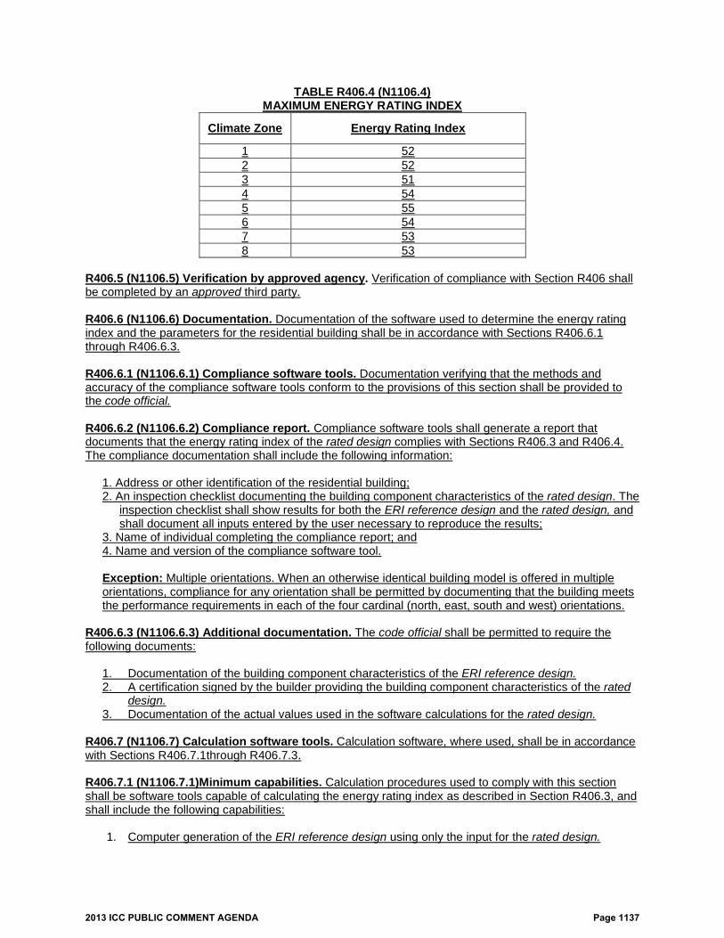
TABLE R406.4 (N1106.4) MAXIMUM ENERGY RATING INDEX
Climate Zone Energy Rating Index
1 52 2 52 3 51 4 54 5 55 6 54 7 53 8 53
R406.5 (N1106.5) Verification by approved agency. Verification of compliance with Section R406 shall be completed by an approved third party. R406.6 (N1106.6) Documentation. Documentation of the software used to determine the energy rating index and the parameters for the residential building shall be in accordance with Sections R406.6.1 through R406.6.3. R406.6.1 (N1106.6.1) Compliance software tools. Documentation verifying that the methods and accuracy of the compliance software tools conform to the provisions of this section shall be provided to the code official. R406.6.2 (N1106.6.2) Compliance report. Compliance software tools shall generate a report that documents that the energy rating index of the rated design complies with Sections R406.3 and R406.4. The compliance documentation shall include the following information:
1. Address or other identification of the residential building; 2. An inspection checklist documenting the building component characteristics of the rated design. The
inspection checklist shall show results for both the ERI reference design and the rated design, and shall document all inputs entered by the user necessary to reproduce the results;
3. Name of individual completing the compliance report; and 4. Name and version of the compliance software tool.
Exception: Multiple orientations. When an otherwise identical building model is offered in multiple orientations, compliance for any orientation shall be permitted by documenting that the building meets the performance requirements in each of the four cardinal (north, east, south and west) orientations.
R406.6.3 (N1106.6.3) Additional documentation. The code official shall be permitted to require the following documents:
1. Documentation of the building component characteristics of the ERI reference design. 2. A certification signed by the builder providing the building component characteristics of the rated
design. 3. Documentation of the actual values used in the software calculations for the rated design.
R406.7 (N1106.7) Calculation software tools. Calculation software, where used, shall be in accordance with Sections R406.7.1through R406.7.3. R406.7.1 (N1106.7.1)Minimum capabilities. Calculation procedures used to comply with this section shall be software tools capable of calculating the energy rating index as described in Section R406.3, and shall include the following capabilities:
1. Computer generation of the ERI reference design using only the input for the rated design.
2013 ICC PUBLIC COMMENT AGENDA Page 1137

The calculation procedure shall not allow the user to directly modify the building component characteristics of the ERI reference design.
2. Calculation of whole-building, as a single zone, sizing for the heating and cooling equipment in the
ERI reference design residence in accordance with Section R403.6. 3. Calculations that account for the effects of indoor and outdoor temperatures and part-load ratios on
the performance of heating, ventilating and air-conditioning equipment based on climate and equipment sizing.
4. Printed code official inspection checklist listing each of the rated design component characteristics determined by the analysis to provide compliance, along with their respective performance ratings.
R406.7.2 (N1106.7.2) Specific approval. Performance analysis tools meeting the applicable sections of Section R406 shall be approved. Tools are permitted to be approved based on meeting a specified threshold for a jurisdiction. The code official shall approve tools for a specified application or limited scope. R406.7.3 (N1106.7.3) Input values. When calculations require input values not specified by Sections R402, R403, R404 and R405, those input values shall be taken from an approved source. Add new definitions as follows: RATED DESIGN. A description of the proposed building used to determine the energy rating index. ERI REFERENCE DESIGN. A version of the rated design that meets the minimum requirements of the 2006 International Energy Conservation Code. Reason: The residential provisions of the IECC allows for varying methods for demonstrating compliance with the code. This includes both a prescriptive and simulated performance option in addition to allowing efficiency programs that are designed to go above the minimum code levels as “deemed to comply” programs. These above code programs must be approved by the code official to be used in the jurisdiction. Alternative programs that depend on an Energy Rating Index (ERI) have been approved as an alternative code or above code program in at least 6 states and in over 130 jurisdictions. These types of programs typically take the form of a Home Energy Rating System (HERS) program. Under the current code there is no guidance on setting Energy Rating Index scores, which will lead to inconsistent application of these types of programs based on climate zones.
The goal of this proposal is to introduce an Energy Rating Index with established rating numbers into the code that will allow alternative programs to be designed to meet these criteria. The proposal provides guidelines for the development of the index, documentation provided to ensure compliance and a requirement that an approved 3rd party verify that the building complies with the applicable Energy Rating Index. The reference house is based on a home built to the 2006 IECC which is consistent with ERI based programs.
The 2009 IECC residential envelope requirements have been set as the least efficient level of efficiency for potential trade-offs to ensure that minimum levels of efficiency that have proven to be cost effective are installed in all buildings and that some flexibility is allowed in the approach to alternative designs. This proposal also requires complying with the applicable mandatory requirements to be consistent with the Above Code section in the IECC. And because energy losses in the domestic hot water distribution system fall outside the scope of the energy rating index as it can be calculated with 2013 methodology, current code provisions relating to hot water pipe insulation are mandatory as well. We anticipate that these requirements can be folded into the energy rating index for the 2018 IECC and thus removed from the mandatory sections then.
This proposal is intended to produce substantial additional energy savings compared to the current or proposed levels of prescriptive requirements in the 2015 IECC while allowing considerably greater flexibility to builders using a method with which a large segment of the market is already familiar. This flexibility is likely to result in lower construction costs for any given level of energy efficiency. Builders who do not make use of this proposed method are still able to comply with the Code can still use any of the existing compliance pathways. Cost Impact: The code change proposal will not increase the cost of construction.
R401.2-EC-GOLDSTEIN-MAKELA.DOC
Committee Action Hearing Results Committee Action: Approved as Submitted
2013 ICC PUBLIC COMMENT AGENDA Page 1138

Committee Reason: This proposal, while providing 20% more stringency, provides a system that has considerably more flexibilitty for achieving energy efficiency. Rating systems are becoming a more common approach, with straightforward options that are being more widely used in the construction marketplace. Assembly Action: None
Individual Consideration Agenda
This item is on the agenda for individual consideration because public comments were submitted. Public Comment 1: Brian Dean, ICF International, representing the Energy Efficient Codes Coalition; Jeff Harris, Alliance to Save Energy; Harry Misuriello, American Council for an Energy-Efficient Economy (ACEEE); Bill Prindle, representing the Energy Efficient Codes Coalition; Garrett Stone, Brickfield, Burchette, Ritts & Stone, PC; Donald J. Vigneau, Northeast Energy Efficiency Partnerships Inc., request Approval as Modified by this Public Comment. Modify the proposal as follows:
R406.2 (N1106.2) Mandatory requirements. Compliance with this section also requires that sections identified as the “mandatory” in this chapter be met and that provisions identified in Section R401.2 and R403.4.2 be met. The the building thermal envelope shall be greater than or equal to levels of efficiency meet the prescriptive requirements of Section R402.1 of this code. and Solar Heat Gain Coefficient in Table 402.1.1 or 402.1.3 of the 2009 International Energy Conservation Code.
(Portions of proposal not shown remain unchanged) Commenter’s Reason: We recommend that RE188 be modified in accordance with this public comment. This public comment does not address the specifics of the proposed new home energy rating compliance approach, but instead focuses on creating reasonable assurance that homes using the new method will install a reasonable thermal envelope. Although we recognize the efforts of the proponents to attempt to establish effective limitations on the ability to trade away the efficiency of the permanent thermal envelope for shorter-lived equipment and appliances under a home energy rating approach, we are concerned that the original proposal still has the potential to give away too much long-term energy efficiency. The permanent prescriptive thermal envelope of the 2012 IECC is considerably more robust than the 2009 IECC. Although the proposed home energy rating method includes thermal envelope components in its calculation, several other components are also part of the equation that are not currently allowed under the IECC. Using the proposed home energy rating method, builders may take credits for equipment, appliances, lighting and a different performance baseline, potentially leading to homes built with less-efficient thermal envelopes and more efficient short-lived products. As a result, we believe that there needs to be a better backstop in this proposal to avoid undoing the progress made in improving the permanent thermal envelope in the 2012 IECC.
The modification proposed above attempts to strike a balance between efficiency and flexibility. The modification updates the reference to minimum thermal performance (prescriptive R-values, U-factors and SHGCs) to the current IECC requirements (section R402.1) instead of the 2009 IECC, but the modification allows all prescriptive options for demonstrating compliance with the thermal envelope prescriptive requirements (including Total UA). This will allow builders the most flexibility in demonstrating that the thermal envelope meets or exceeds the 2012 IECC, while avoiding an unnecessary weakening of the thermal envelope requirements of the current code through equipment, appliance and other trade-offs. Public Comment 2: Eric Makela, Britt/Makela Group, representing self, Ron Burton, representing Leading Builders of America, David Goldstein, representing National Resource Defense Council, and Meg Waltner, representing National Resource Defense Council, request Approval as Modified by this Public Comment. Modify the proposal as follows: R406.4 ERI based compliance. Compliance based on an ERI analysis requires that the rated design be shown to have an ERI less than or equal to the appropriate value listed in Table R406.3, when compared to the ERI reference design.
2013 ICC PUBLIC COMMENT AGENDA Page 1139

Table R406.4 Maximum Energy Rating Index
Climate Zone
Energy Rating Index
1 52 59 2 52 59 3 51 59 4 54 63 5 55 63 6 54 62 7 53 60 8 53 60
(Portions of proposal not shown remain unchanged) Public Comment 3: Ryan Meres, Institute for Market Transformation, representing self, requests Approval as Modified by this Public Comment. Modify the proposal as follows: ERI REFERENCE DESIGN. A version of the rated design that meets the minimum requirements of Tables 404.5.2(1) and 404.5.2(2) of the 2006 International Energy Conservation Code.
SECTION R406 ENERGY RATING INDEX COMPLIANCE ALTERNATIVE
R406.1 Scope. This section establishes criteria for compliance using an Energy Rating Index analysis. R406.2 Mandatory requirements. Compliance with this section requires that the mandatory provisions identified in Section R401.2 and the provisions identified in Section R403.4.2 be met. The building thermal envelope shall be greater than or equal to levels of efficiency and Solar Heat Gain Coefficient in Table 402.1.1 or 402.1.3 of the 2009 International Energy Conservation Code. Solar Heat Gain Coefficient shall be no greater than the levels in Table 402.1.1 of the 2009 International Energy Conservation Code. Exceptions:
1. All supply and return ducts not completely inside the building thermal envelope shall be insulated to a minimum of R-6.
R406.3 Energy Rating Index. The ERI shall be a numerical integer value that is based on a linear scale constructed such that the ERI reference design has an Index value of 100 and a home that uses no net purchased energy has an Index value of 0. Each integer value on the scale shall represent a one percent (1%) change in the total energy use of the rated design relative to the total energy use of the ERI reference design. The ERI shall consider all energy used in the dwelling unit. The ERI shall consider all energy loads used in the dwelling unit as regulated by the provisions of this code including lighting and plug loads installed at the time of final inspection. R406.3.1 ERI Reference Design. The ERI reference design shall be configured such that is it meets the minimum requirements of the 2006 International Energy Conservation Code prescriptive requirements The proposed residence shall be shown to have an annual total normalized Modified Loads that are less than or equal to the annual total Loads of the ERI reference design. R406.4 ERI based compliance. Compliance based on an ERI analysis requires that the rated design be shown to have an ERI less than or equal to the appropriate value listed in Table R406.3, when compared to the ERI reference design.
Table R406.4 Maximum Energy Rating Index
Climate Zone
Energy Rating Index
1 52 2 52 3 51 4 54 5 55 6 54 7 53 8 53
2013 ICC PUBLIC COMMENT AGENDA Page 1140

R406.4 Verification by approved agency. Verification of compliance with Section R406 shall be completed by an approved third party. R406.4.1 Equipment and device verification. The efficiency of the equipment and devices used for the proposed design shall be specified in the construction documents. The equipment or device efficiency shall be readily observable for inspection after the equipment or device is installed. R406.5 Documentation. Documentation of the software used to determine the energy rating index and the parameters for the building shall be in accordance with Sections R406.5.1through R406.5.3. R406.5.1 Compliance software tools. Documentation verifying that the methods and accuracy of the compliance software tools conform to the provisions of this section shall be provided to the code official. R406.5.2 Compliance report. Compliance software tools shall generate a report that documents that the energy rating index of the rated design complies with Sections R406.3 and R406.4. The compliance documentation shall include the following information:
1. Address or other identification of the residence; 2. An inspection checklist documenting the building component characteristics of the rated design. The inspection checklist shall
show results for both the ERI reference design and the rated design, and shall document all inputs entered by the user necessary to reproduce the results;
3. Name of individual completing the compliance report; and 4. Name and version of the compliance software tool.
Exception: Multiple orientations. When an otherwise identical building model is offered in multiple orientations, compliance for any orientation shall be permitted by documenting that the building meets the performance requirements in each of the four cardinal (north, east, south and west) orientations.
R406.5.3 Additional documentation. The code official shall be permitted to require the following documents:
1. Documentation of the building component characteristics of the ERI reference design. 2. A certification signed by the builder providing the building component characteristics of the rated design. 3. Documentation of the actual values used in the software calculations for the rated design.
R406.6 Calculation software tools. Calculation software, where used, shall be in accordance with Sections R406.6.1through R406.6.3. R406.6.1 Minimum capabilities. Calculation procedures used to comply with this section shall be software tools capable of calculating the energy rating index as described in Section R406.3, and shall include the following capabilities:
1. Computer generation of the ERI reference design using only the input for the rated design. The calculation procedure shall not allow the user to directly modify the building component characteristics of the ERI reference design.
2. Calculation of whole-building (as a single zone) sizing for the heating and cooling equipment in the ERI reference design
residence in accordance with Section R403.6. 3. Calculations that account for the effects of indoor and outdoor temperatures and part-load ratios on the performance of
heating, ventilating and air-conditioning equipment based on climate and equipment sizing. 4. Printed code official inspection checklist listing each of the rated design component characteristics determined by the analysis
to provide compliance, along with their respective performance ratings. 5. Calculations that account for the differences in the heating, cooling and hot water equipment efficiencies of the reference
design and the proposed design, and normalize for the differences in fuel types.
R406.6.2 Specific approval. Performance analysis tools meeting the applicable sections of Section R406 shall be approved. Tools are permitted to be approved based on meeting a specified threshold for a jurisdiction. The authority having jurisdiction shall approve tools for a specified application or limited scope. R406.6.3 Input values. When calculations require input values not specified by Sections R402, R403, R404 and R405, those input values shall be taken from an approved source. (Portions of proposed change not shown remain unchanged.) Commenter’s Reason: This Public Comment addresses some of the issues that were raised at the IECC Code Development Hearings and also input from key stakeholders. The public comment clarifies the language. It specifically accounts for all energy using features in the building as long as the feature is present and installed at the time of final inspection. Alternative programs that depend on an Energy Rating Index (ERI) have been approved as an alternative code or above code program in at least 6 states and in over 130 jurisdictions. These types of programs typically take the form of a Home Energy Rating
2013 ICC PUBLIC COMMENT AGENDA Page 1141

System (HERS) program. Under the current code there is no guidance on setting Energy Rating Index scores, which will lead to inconsistent application of these types of programs based on climate zones.
The goal of this proposal is to introduce an Energy Rating Index with established rating numbers into the code that will allow alternative programs to be designed to meet these criteria. The proposal provides guidelines for the development of the index, documentation provided to ensure compliance and a requirement that an approved 3rd party verify that the building complies with the applicable Energy Rating Index. The reference house is based on a home built to the 2006 IECC which is consistent with ERI based programs.
The 2009 IECC residential envelope requirements have been set as the least efficient level of efficiency for potential trade-offs to ensure that minimum levels of efficiency that have proven to be cost effective are installed in all buildings and that some flexibility is allowed in the approach to alternative designs. This proposal also requires complying with the applicable mandatory requirements to be consistent with the Above Code section in the IECC. And because energy losses in the domestic hot water distribution system fall outside the scope of the energy rating index as it can be calculated with 2013 methodology, current code provisions relating to hot water pipe insulation are mandatory as well.
This proposal is intended to produce substantial additional energy savings compared to the current or proposed levels of prescriptive requirements in the 2015 IECC while allowing considerably greater flexibility to builders using a method with which a large segment of the market is already familiar. This flexibility is likely to result in lower construction costs for any given level of energy efficiency. Builders who do not make use of this proposed method are still able to comply with the Code can still use any of the existing compliance pathways.
The IECC Code Development committee had this to say about RE-188: “This proposal, while providing 20% more stringency, provides a system that has considerably more flexibility for achieving energy efficiency. Rating systems are becoming a more common approach, with straightforward options that are being more widely used in the construction marketplace.” Public Comment 4: Craig Conner, Building Quality, representing self, requests Disapproval. Commenter’s reason: (Conner): The reason statement makes it clear that the proponents are trying to promote alternative programs for code compliance, a worthy goal. I think we are all strongly in favor of enabling alternative programs / above-code programs to be used for code compliance. However, this proposal is vague, inconsistent, and too close to proprietary. Moreover, it has restrictions that are not justified, nor has the selection of the specific “energy reference index” values been justified.
This proposal attempts to regulate or at least include ““all energy used in the residential building” (new R406.3). How does one regulate appliances that may not even be present at the time of inspection? What would be the minimum energy efficiency for the nonexistent appliances? How does one regulate what is just plugged into the wall?
There is no analysis supporting the specific numbers in the new table titled “Maximum Energy Rating Index”. Those values are the core of this proposal and the values appear to be arbitrary.
A specific HERS score is not an accurate predictor of code compliance. EPA and DOE reached a similar conclusion for the Energy Star and Builder's Challenge programs. Neither uses a specific HERS score for a climate zone. EPA said "Given a constant set of energy efficiency features, these design features can alter the HERS index up to several points for individual factors and greater than 15 points by combining several factors into configurations often encountered in the real world."1 A summary of this EPA analysis is available.2 The Energy Star response was to require that a HERS score be recomputed for every building, and not to allow the same score for specific climate zones.3 Likewise DOE requires a HERS score to be recomputed to each residence and does not allow a single HERS score for a whole climate zone.4
The stated goal of this proposal is flexibility; however in some ways this code change proposes the opposite of flexibly. This proposal places restrictions on insulation levels and glazing based on not allowing tradeoffs below the levels in the 2009 IECC (new R406.2). In some cases the 2009 and 2012 have the same requirement, so that tradeoff is not allowed at all. Nowhere are those specific restrictions justified through data or analysis. Comparing the 2012 and 2009 IECC shows tradeoffs that would not be allowed. In Zone 1 insulation is not tradable, as the 2009 and 2012 are the same. Floor insulation could only be traded in zone 5. Basement wall insulation is tradable only in Zone 5? Why? What makes insulation tradeoffs for basements and floors very bad? The 2009 IECC itself would allow those same tradeoffs, made up somewhere else, based on UA calculations or its own performance path.
The Energy Rating Index is not defined in a usable or easily understood manner. Unreasonable restrictions are included. For example, why require (not allow, but require) a 100 to 0 decreasing scale? Why would other scales not be allowed if they demonstrated compliance? Examples of other scales: --DOE has a Home Energy Score that goes from 1 to 10, with10 the best.5 --ICC’s “National Green Building Standard” (ICC 700-2012) has points. Higher is better. 120 energy points is very good and not easy to get. 10 points would be a terrible home. --The Energy Performance Score goes from 0 to at least 200.6 In the sentence “The ERI shall consider all energy used in the residential building.” What does “consider” mean? “Consider” is not a good word for the I-codes.
It is odd to reference the 2006 IECC (new R406.3.1) and the 2009 IECC (new R406.2) in the 2015 IECC. If there are limitations on the 2018 IECC based on values from previous versions of the IECC, those limitations should be included in the 2015 code so that it becomes a standalone code.
The term “normalized Modified Loads” is not defined or explained (new R06.3.1). There are no calculations specified. It is not a term in common use. IECC Section R201.4 says “terms not defined … shall have ordinarily accepted meanings such as the context implies.” In an energy context “normalized” most commonly refers to heating and cooling energy that is normalized for weather variation. The proposal also used the word “Modified”. How and why are the loads modified? This change covers “all
2013 ICC PUBLIC COMMENT AGENDA Page 1142

energy used in the residential building”. How are “normalized” and “modified” applied to the lighting, or appliances not specifically named in the IECC (dishwasher, refrigerator, etc.). And how is what are usually called “plug loads” to be “normalized” or “modified”?
In using the term “normalized Modified Loads” the proponents appear to be attempting to reference something used by RESNET in its home energy ratings. If this is correct, they have named a different form of the adjustment or at least incorrectly named it. Do they mean the “normalized Modified End Use Loads”?7 No other alternative program or above code program I can find uses this “normalized Modified Loads” or “normalized Modified End Use Loads”.
As worded, this change is proprietary. Requiring a 0 to 100 decreasing metric and a “normalized Modified Load” (assuming the name was corrected) results in only one group’s product meeting this criteria. That group is RESNET. We should avoid even the appearance of proprietary systems in the I-Codes. . There are many other programs, both local and national, and the code should not promote just one of them, picked arbitrarily by the proponents.
If somehow referencing HERS in the code is the goal, or one of the goals, the proponents should at least wait until RESNET completes its ANSI consensus review process. RESNET does not yet have any ANSI approved documents that could be referenced. Or the proponents could work through some part of the Chapter 1 alternative programs (“above code programs”) process. References: 1. Overview of Evolving ENERGY STAR Qualified Homes Program & Methodology for Estimating Savings. See page 4, key feature #4. http://www.energystar.gov/ia/partners/bldrs_lenders_raters/downloads/2011_Technical_Background.pdf 2. EPA Response to RESNET’s Comments on the Proposed ENERGY STAR 2011 Qualified New Homes Guidelines https://www.energystar.gov/ia/partners/bldrs_lenders_raters/downloads/EPA_Response_to_RESNET.pdf 3. ENERGY STAR Qualified Homes, Version 3 (Rev. 03) HERS Index Target Procedure For National Program Requirements http://www.energystar.gov/ia/partners/bldrs_lenders_raters/downloads/V3HERS_IndexTargetProcedure.pdf 4. DOE Challenge Home HERS Index Target Procedure for National Home Requirements, April 1, 2012 http://www2.eere.energy.gov/buildings/residential/pdfs/challenge_home_hers_target_4-12.pdf 5. Home Energy Score http://www1.eere.energy.gov/buildings/residential/hes_index.html 6. Energy Performance Score http://energytrust.org/residential/new-home-solutions/eps.aspx 7. RESNET Mortgage Industry National HERS Standards. See page 3-3, equation 1. http://www.resnet.us/standards/RESNET_Mortgage_Industry_National_HERS_Standards.pdf Public Comment 5: Neil Leslie, Gas Technology Institute, representing self, requests Disapproval. Commenter’s reason: RE188-13 is incomplete and unenforceable because it does not provide citable standards necessary for proper implementation and enforcement. Specifically, RE188-13 requires that “The proposed residential building shall be shown to have an annual total normalized Modified Loads that are less than or equal to the annual total Loads of the ERI reference design.” Yet there is no guidance on how to determine the normalized modified loads. For this reason alone, RE188-13 should be disapproved. Despite the lack of guidance on normalized modified load calculations in RE188-13, it is nearly certain that the proposal intends to use the RESNET normalized modified end use loads (nMEUL) methodology fully detailed in BSR/RESNET 301-2013 “Standard for the Calculation and Labeling of the Energy Performance of Low-Rise Residential Buildings using the HERS Index.” Assuming this is the basis of the compliance requirement, RE188-13 must be disapproved due the technical flaws and biases embodied in the RESNET nMEUL methodology. Unfortunately for the code official, the technical flaws and biases embodied in RE188 are hidden from view. The flaws are in the “black box” that code officials are being asked to accept as an alternative compliance mechanism to the energy code requirements. For brevity, this reason statement will focus on ONE technical flaw (and subsequent biases) that should more than justify disapproval of RE188-13 by building officials.
First, the nMEUL methodology utilizes separate, inequitable reference home configurations and requirements for all-electric homes compared to homes that also use fossil fuels. This hurts homebuyers, home builders, and many others in that it ignores fuel-specific efficiency benefits by having different base cases depending on what fuel is used for heating, air conditioning and hot water. This means a different set of rules depending on fuel source. This is technically wrong and sends grossly inaccurate signals to the marketplace on ratings and fuel choices. It also puts the code official in the very awkward position of hoping that some rating number actually meets the requirements and intent of the code.
The rating methodology also contains biased normalized gas efficiency improvement potentials relative to the “baseline” electricity efficiency improvement potential for heating and water heating (but not cooling) appliances. A good example of this key technical deficiency in the nMEUL rating method is its treatment of the reference electric heating and water heating technologies as equivalent to natural gas technologies from a home energy performance rating perspective, even though their primary energy efficiencies (as well as consumer cost and associated greenhouse gas emissions) are significantly different. The authors of the nMEUL methodology acknowledge this inequitable treatment and attempt to address it for higher efficiency options based on available market “potential” for efficiency improvement. As a result, the nMEUL method gives excess credit to higher efficiency natural gas heating and water heating options (but not gas cooling) relative to the gas reference design. A simple example will show these points. Homes using NAECA minimum efficiency electric resistance storage water heating receive an identical HERS score as a NAECA minimum gas storage water heater, even though both the annual energy costs and primary energy consumption are much higher for the resistance water heater than for the gas water heater (typically twice as high). This “separate but equivalent” bias was never fixed in the nMEUL methodology as it was rolled out in the RESNET programs. The
2013 ICC PUBLIC COMMENT AGENDA Page 1143

other bias negatively and disproportionately affects fossil fuel appliances at conventional efficiency levels, but the normalizing biases favor ultra-high efficiency gas technologies (such as gas heat pumps) at the expense of equivalent electric technologies.
So this isn’t about gas versus electricity. It is about a single reference building where all constructions and fuels can be equally and equitably compared. It is about technical flaws in the “black box”. It is about putting code officials at risk, along with builders and buyers, who want assurance of energy code compliance on a level playing field. RE188 fails these most basic code equity requirements. Disapprove RE188. Public Comment 6: Steve Rosenstock, representing Edison Electric Institute, requests Disapproval. Commenter’s reason: This proposal should be disapproved for the following reasons: -It is a “backdoor” attempt to allow the use of HERS as a compliance path. In other actions, the code development committee specifically voted against the use of HERS as a compliance path. Disapproval would be consistent with the other committee actions. -There is no information about the costs or energy savings to obtain an “ERI” of 51-55, depending on the climate zone. -Under this alternative, a building that uses “no net purchased energy has an index of 0”. As a result, a building could use 5 or 10 or 20 times the amount of energy of another building (that is much more energy efficient) as long as it has enough on-site renewable energy to “net out” the energy purchased from the grid. This type of credit for on-site renewable energy will not lead to more energy efficient homes, especially if the prices of renewable energy systems keep dropping at a dramatic pace. Energy production is not the same as energy efficiency, and building codes should not mix them together. RE188-13 Final Action: AS AM AMPC D
2013 ICC PUBLIC COMMENT AGENDA Page 1144

RE190-13 R406 (New) (IRC N1106 (New))
Proposed Change as Submitted Proponent: Robby Schwarz, EnergyLogic Inc., Representing EnergyLogic, Inc. ([email protected]) Add new text as follows:
SECTION R406 (N1106) SIMULATED PERFORMANCE BY
INDEX SCORE METHOD (PERFORMANCE)
R406.1 (N1106.1) Scope. The simulated performance index score method in Section R406 shall be used for determining that a building complies with this code. Such methods shall include a whole house energy analysis resulting in comparative index scores. R406.2 (N1106.2) Mandatory requirements. Use of the simulated performance index score alternative method for compliance to this code shall require all of the following:
1. Design and construction of the building in compliance with sections in this code that are indicated as mandatory.
2. Inspections, required for the generation of an index score, are performed including, but not limited to, inspection, by the entity or person performing the energy analysis, of insulation systems and air barriers prior to concealment.
3. Supply and return ducts not completely inside the building thermal envelope are insulated with not less than an R-value of R-8.
4. Ductwork, that is either partially or completely within the thermal layer of the wall system of the building thermal envelope, shall have insulation of a R-value of not less than R-10 on the side of the duct that is away from the conditioned space. Where the duct is in a wall cavity and the R-10 insulation does not completely fill the cavity, the remaining cavity space shall be filled with insulation to the extent that the requirement for insulating the exterior wall of the building is met or the cavity space is completely filled, whichever is less. Ductwork, that is either partially or completely within the thermal layer of a floor system of the building thermal envelope, shall have insulation of a R-value of not less than R-19 on the side of the duct that is away from the conditioned space. Floor cavity insulation shall be installed in accordance with Section R402.2.7. Where the duct is in a floor cavity and the R-19 insulation does not completely fill the cavity, the remaining cavity space shall be filled with insulation to the extent that the requirement for insulating the floor system of the building is met or the cavity space is completely filled, which ever is less.
R406.3 (N1106.3) Performance-based compliance. The proposed building (proposed design) shall be complaint witht his code where the index score generated by the energy analysis is less than or equal to the index score of the standard reference design. The standard reference design index score shall be determined by analyzing a building of identical geometry to the proposed building that has the features indicated in the standard reference design column of Table R405.5.2(1). The index score of the proposed design shall be calculated in accordance with RESNET Standards.
R406.3.1 (N1106.3.1) Compliance software tools. Software tools used to determine code compliance by the simulated performance index score method shall be accredited by the Residential Energy Services Network organization. Documentation showing the software accreditation shall be provided to the code official.
2013 ICC PUBLIC COMMENT AGENDA Page 1145

R406.4 (N1106.4) Compliance report and other documentation. Compliance reports and other documentation shall be provided in accordance with Sections R406.4.1 through R406.4.3. A compliance report on the proposed design shall be submitted with the application for the building permit. Upon completion of the building, a compliance report based upon the as-built condition of the building, shall be submitted to the code official before a certificate of occupancy is issued by the code official. Batch sampling of buildings to determine energy code compliance for all buildings in the batch shall be prohibited. Compliance reports shall include information in accordance with Sections R405.4.2.1 and R405.4.2.2. Where the proposed design of a building could be built on different sites where the cardinal direction orientation of the building on each site is different, compliance of the proposed design for the purposes of the application for the building permit, shall be based upon the worst case orientation worst case configuration, worst case building air leakage and worse case duct leakage. Such worse case parameters shall be used as inputs to the compliance software for energy analysis. R406.4.1 (N1106.4.1) Compliance report for permit application. A compliance report submitted with the application for building permit shall include all of the following:
1. Building street address, or other building site identification. 2. A statement indicating that the proposed design complies with Section R405.3. 3. An inspection checklist documenting the building component characteristics of the proposed
design as indicated in Table R405.5.2(1). The inspection checklist shall show results for both the standard reference design and the proposed design with all user inputs to the compliance software to generate the results.
4. A site-specific energy analysis report that is in compliance with Section R405.3 5. Name of the individual performing the analysis and generating the report. 6. Name and version of the compliance software tool.
R406.4.2 (N1106.4.2) Compliance report for certificate of occupancy. A compliance report submitted for obtaining the certificate of occupancy shall include all of the following:
1. Building street address, or other building site identification 2. A statement indicating that the as-built building complies with Section R405.3. 3. A certificate indicating that the building meets the requirements of the home energy rating
system, HERS, index matrix of the RESNET Standards for code compliance and the energy saving features of the buildings.
4. A site-specific energy analysis report that is in compliance with Section R405.3. 5. Name of the individual performing the analysis and generating the report. 6. Name and version of the compliance software tool.
R406.4.3 (N1106.4.3) Additional documentation. Upon request by the code official, the following documentation shall be provided along with compliance reports to the code official:
1. Documentation of the building component characteristics of the standard reference design. 2. A certification statement, signed by the builder, that lists the proposed design building component characteristics indicated in Table R405.5.2(1).
R406.5 (N1106.5) Calculation procedure. Calculations of the energy performance of a building design shall be in accordance with Sections R406.5.1 and R406.5.2.
R406.5.1 (N1106.5.1) Identical methods. The standard reference design and proposed design shall be configured and analyzed using identical methods and techniques to generate a separate index score for each configuration of the buildingThe methods and techniques shall be in accordance with the home energy efficiency rating system, HERS, guidelines in the RESNET Standards.
2013 ICC PUBLIC COMMENT AGENDA Page 1146

R406.5.2 (N1106.5.2) Building design specifications. The standard reference design and proposed design shall be configured and analyzed as indicated in Table R405.5.2(1). R406.6 (N1106.6) Calculation software tools. Calculation software shall be in accordance with Sections R406.6.1 through R406.6.3. R406.6.1 (N1106.6.1) Minimum capabilities. Software tools shall be capable of calculating the index score of all building elements that differ between the standard reference design and the proposed design. The software shall have the following capabilities:
1. Computer generation of a report for the standard reference design using only the input for the proposed design. The calculation software shall prohibit the user from directly modifying the building component characteristics of the standard reference design. 2. Calculation of whole-building sizing , as a single zone, for the heating and cooling equipment in the standard reference design building in accordance with Section R403.6. 3. Calculations that account for the effects of indoor and outdoor temperatures and part-load ratios on the performance of heating, ventilating and air-conditioning equipment based on climate and equipment sizing. 4. Printing an inspection checklist for the code official that lists the characteristic of each of the proposed design components indicated in Table R405.5.2(1) that was used to determine compliance. The component characteristics shall include the performamce rating for the component such as, but not limited to, R-value, U-factor, SHGC, heating seasonal performance factor-HSPF, annual fuel utilization efficiency-AFUE, seasonal energy efficiency ratio-SEER and energy factor-EF.
R406.6.2 (N1106.6.2) Specific approval. Energy performance analysis tools that do not have accreditation by the Residential Energy Services Network organization shall comply with all other requirements of Section 406 and such tools shall only be used where the tool is approved. R406.6.3 (N1106.6.3) Input values. Where calculations or software programs require input values that are not specified in Sections R402, R403, R404, R405 and R406, the input values used shall be only from approved sources. Add new standard to Chapter 5 as follows: Residential Energy Services Network, Inc. P.O. Box 4561 Oceanside, CA 92052-4561 RESNET RESNET Standards-2013 RESNET Mortgage Industry National Home Energy Rating Standards. Reason: The current annual energy cost matrix for demonstrating code compliance is flawed and may demonstrate that a house that should pass the energy code, based on actual geometry and energy specifications, may not only because the energy costs in a region have changed. More and more jurisdiction and builders across the country are turning to performance index scores to represent the efficiency of a home and to demonstrate code compliance. Performance scores in and of themselves do not necessarily demonstrate code compliance. However, if the score is imposed on the existing structure of the code as this new alternative compliance path section 406 does, the score can reflect code compliance simply as a means of demonstrating passing and failing.
The current structure of the simulated performance path requires that the mandatory sections of the IECC be complied with, thus ensuring that house performance is maintained and that the score is only a measure to demonstrate compliance. In addition, this new section 406 utilizes the code reference home as described in table 405.5.2(1) and therefore energy code compliance utilizing this pathway will have a score that is variable for each qualified home. This is accomplished through the 2015 IECC Reference Design outlined in table 405.5.2(1). When the builder’s proposed designed home is configured with the IECC reference design features and modeled using approved software, the resulting score becomes the basis for the performance score target for that home.
2013 ICC PUBLIC COMMENT AGENDA Page 1147

The EPA Energy Star program and the DOE Challenge Home program utilize this same matrix for demonstrating qualification for their programs and have demonstrated that the compliance path described in this new section 406 will set the score target for the performance path equal to the performance that would be achieved if the prescriptive path was followed for each individual home. In this way jurisdictions can avoid developing a fixed value, or performance index score, which really has no bearing on compliance and instead set the index score threshold required for energy code compliance at the same value that the same house would earn if configured to the IECC prescriptive path, as outlined in table 405.5.2(1) Reference Design. ** Footnote to Energy Star and DOE Challenge Home program documents Jurisdiction, Builders, third party inspection companies and others are not clear of the process for completing and utilizing the simulated performance path. With all pathways through the energy code one must in essence declare how they will meet the intent of the code. For the prescriptive path they simply say they are going prescriptive, for the UA trade off path they submit a document such as a RESCheck report, and for the simulated performance path they must currently submit a document demonstrating that the annual energy cost of the proposed design are less than or equal to the same home if it were built with the reference design specification. It becomes unclear how one demonstrates that they have carried out their proposed design. The revisions proposed for this section clearly outlines a process by which the proposed design is submitted, inspections take place, and additional analysis is preformed to ensure that the proposed design was achieved or bettered for the purposes of compliance. Field inspection, in order to create an accurate computer generated energy analysis, should be required for following reasons:
1. For production building a plan is often mastered and that one plan may be built over 100 times. To ensure that each house meets the performance analysis each home must be inspected.
2. Computer generated energy analysis’ utilizes worst case configuration of the proposed design and requires evaluations and inputs that must be confirmed in the specific home that is built to ultimately determine if the actually built home meets the intent of the energy code. Examples of this are worst case air leakage and duct leakage numbers but also orientation, window square footage, number of bedrooms, and foundation type.
3. The reality is that houses built from a set of plans change. The actual built home may generally reflect the homes plans but window square footage, orientation, and even insulation and mechanical equipment are often different from what was proposed. The inspection process ensures that the energy analysis is address and site specific which ultimately ensures that the home that received its permit from the proposed design’s energy analysis has carried out what they have proposed, which is to meet the intent of the code, even if each component of the home is not exactly the same as what was on the set of plans.
Cost Impact: The code change proposal will not increase the cost of construction more than is already done by the current section R405 simulated performance path. Analysis: A review of the standards proposed for inclusion in the code, RESNET Standards, with regard to the ICC criteria for referenced standards (Section 3.6 of CP#28) will be posted on the ICC website on or before April 1, 2013. R406T (NEW)-EC-SCHARZ.DOC
Committee Action Hearing Results Committee Action: Disapproved Committee Reason: The standard proposed for inclusion in the code does not comply with CP#28, Section 3.6. Assembly Action: None
Individual Consideration Agenda
This item is on the agenda for individual consideration because a public comment was submitted. Public Comment: Robby Schwarz, EnergyLogic, Inc., requests Approval as Modified by this Public Comment. Modify the proposal as follows:
SECTION R406 (N1106)
SIMULATED PERFORMANCE BY INDEX SCORE METHOD ALTERNATIVE
(PERFORMANCE)
2013 ICC PUBLIC COMMENT AGENDA Page 1148

R406.1 (N1106.1) Scope. The simulated performance index score method in Section R406 shall be used for This section establishes criteria using simulated energy performance analysis resulting in an Index score used to determining that a building complies determine compliance with this code. Such This methods method shall include a whole house energy analysis resulting in comparative index scores unique to the reference home and proposed design. R406.2 (N1106.2) Mandatory requirements. Use of the simulated performance index score alternative method for compliance to this code shall require all of the following:
1. Design and construction of the building in compliance with sections in this code that are indicated as mandatory. 2. Inspections, required for the generation of an index score, are performed including, but not limited to, inspection, by the
entity or person performing the energy analysis, of insulation systems and air barriers prior to concealment. 3. Supply and return ducts not completely inside the building thermal envelope are insulated with not less than an R-value
of R-8. 4. Ductwork, that is either partially or completely within the thermal layer of the wall system of the building thermal envelope,
shall have insulation of a R-value of not less than R-10 on the side of the duct that is away from the conditioned space. Where the duct is in a wall cavity and the R-10 insulation does not completely fill the cavity, the remaining cavity space shall be filled with insulation to the extent that the requirement for insulating the exterior wall of the building is met or the cavity space is completely filled, whichever is less. Ductwork, that is either partially or completely within the thermal layer of a floor system of the building thermal envelope, shall have insulation of a R-value of not less than R-19 on the side of the duct that is away from the conditioned space. Floor cavity insulation shall be installed in accordance with Section R402.2.7. Where the duct is in a floor cavity and the R-19 insulation does not completely fill the cavity, the remaining cavity space shall be filled with insulation to the extent that the requirement for insulating the floor system of the building is met or the cavity space is completely filled, whichever is less.
R406.3 (N1106.3) Performance-based compliance. The proposed building (proposed design) shall be complaint compliant with this code where when the index score generated by the energy analysis is less than or equal to the index score of the standard reference design. The standard reference design index score shall be determined by analyzing a building of identical geometry to the proposed building that has the features indicated in the standard reference design column of Table R405.5.2(1). The index score of the proposed design shall be calculated in accordance with RESNET standards Chapter #3 “ National Energy Rating Technical Standard” and shall only analyze the building components described in Table R405.5.2(1) that are common to both homes. R406.3.1 (N1106.3.1) Compliance software tools. Software tools used to determine code compliance by the simulated performance index score method shall be accredited by the Residential Energy Services Network organization or its equivalent. Documentation showing the software accreditation shall be provided to the code official. R406.4 (N1106.4) Compliance report and other documentation. Compliance reports and other documentation shall be provided in accordance with Sections R406.4.1 through R406.4.3. A compliance report on the proposed design shall be submitted with the application for the building permit. Upon completion of the building, a compliance report based upon the as-built condition of the building, shall be submitted to the code official before a certificate of occupancy is issued by the code official. Compliance reports shall include information in accordance with Sections R405.4.2.1 and R405.4.2.2. Where the proposed design of a building could be built on different sites where the cardinal direction orientation of the building on each site is different, compliance of the proposed design for the purposes of the application for the building permit, shall be based upon the worst case orientation worst case configuration, worst case building air leakage and worse case duct leakage. Such worse case parameters shall be used as inputs to the compliance software for energy analysis. R406.4.1 (N1106.4.1) Compliance report for permit application. A compliance report submitted with the application for building permit shall include all of the following:
1. Building street address, or other building site identification. 2. A statement indicating that the proposed design complies with Section R405.3. 3. An inspection checklist documenting the building component characteristics of the proposed design as indicated in Table
R405.5.2(1). The inspection checklist shall show results for both the standard reference design and the proposed design with all user inputs to the compliance software to generate the results.
4. A site-specific energy analysis report that is in compliance with Section R405.3 5. Name of the individual performing the analysis and generating the report. 6. Name and version of the compliance software tool.
R406.4.2 (N1106.4.2) Compliance report for certificate of occupancy. A compliance report submitted for obtaining the certificate of occupancy shall include all of the following: Batch sampling of buildings to determine energy code compliance for all buildings in the batch shall be prohibited.
1. Building street address, or other building site identification 2. A statement indicating that the as-built building complies with Section R405.3. 3. A certificate indicating that the building meets the requirements of the home energy rating system, HERS, index score
matrix of the RESNET Standards for code compliance and the energy saving features of the buildings. 4. A site-specific energy analysis report that is in compliance with Section R405.3. 5. Name of the individual performing the analysis and generating the report. 6. Name and version of the compliance software tool.
2013 ICC PUBLIC COMMENT AGENDA Page 1149

R406.4.3 (N1106.4.3) Additional documentation. Upon request by the code official, the following documentation shall be provided along with compliance reports to the code official:
1. Documentation of the building component characteristics of the standard reference design. 2. A certification statement, signed by the builder, that lists the proposed design building component characteristics indicated in Table R405.5.2(1).
R406.5 (N1106.5) Calculation procedure. Calculations of the energy performance of a building design shall be in accordance with Sections R406.5.1 and R406.5.2. R406.5.1 (N1106.5.1) Identical methods. The standard reference design and proposed design shall be configured and analyzed using identical methods and techniques to generate a separate index score for each configuration of the building. The methods and techniques shall be in accordance with the home energy efficiency rating system, HERS, guidelines in the RESNET Standards Chapter #3 “ National Energy Rating Technical Standard”. R406.5.2 (N1106.5.2) Building design specifications. The standard reference design and proposed design shall be configured and analyzed as indicated in Table R405.5.2(1). R406.6 (N1106.6) Calculation software tools. Calculation software shall be in accordance with Sections R406.6.1 through R406.6.3. R406.6.1 (N1106.6.1) Minimum capabilities. Software tools shall be capable of calculating the index score of all building elements that differ between the standard reference design and the proposed design. The software shall have the following capabilities:
1. Computer generation of a report for the standard reference design using only the input for the proposed design. The calculation software shall prohibit the user from directly modifying the building component characteristics of the standard reference design. 2. Calculation of whole-building sizing , as a single zone, for the heating and cooling equipment in the standard reference design building in accordance with Section R403.6. 3. Calculations that account for the effects of indoor and outdoor temperatures and part-load ratios on the performance of heating, ventilating and air-conditioning equipment based on climate and equipment sizing. 4. Printing an inspection checklist for the code official that lists the characteristic of each of the proposed design components indicated in Table R405.5.2(1) that was used to determine compliance. The component characteristics shall include the performance rating for the component such as, but not limited to; R-value, U-factor, SHGC, heating seasonal performance factor-HSPF, annual fuel utilization efficiency-AFUE, seasonal energy efficiency ratio-SEER and energy factor-EF.
R406.6.2 (N1106.6.2) Specific approval. Energy performance analysis tools that do not have accreditation by the Residential Energy Services Network organization shall comply with all other requirements of Section 406 and such tools shall only be used where the tool is approved by the code official. R406.6.3 (N1106.6.3) Input values. Where calculations or software programs require input values that are not specified in Sections R402, R403, R404, R405 and R406, the input values used shall be only from approved sources. Commenter’s Reason: The committee stated that the original proposal did not comply with CP#28 section 3.6. I believe that CP#28 Code Development Section 3.6 is being followed here with regards to RESNET Standard Chapter #3 “ National Energy Rating Technical Standard” and software accreditation. Specifically section 3.6.3.1 outlines the ability to include reference to a proposed new standard.
• “The standard shall be completed and readily available prior to Final Action Consideration based on the cycle of code development which includes the proposed code change proposal.
• In order for a new standard to be considered for reference by the Code, such standard shall be submitted in at least a consensus draft form in accordance with Section 3.4.
• If a new standard is not submitted in at least draft form, the code change shall be considered incomplete and shall not be processed.
• Updating of standards without corresponding code text changes shall be accomplished administratively in accordance with Section 4.5.
In addition CP#28 states that the standard shall be developed and maintained through a consensus process such as ASTM or ANSI and does not state that is has to be ASTM or ANSI. RESNET has repetealy assured me that Chapter 3 will achieve ANSI approval before the final action hearing in October. However, even if the standard does not it was created utilizing a consensus process as outlined in CP#28.
The current annual energy cost matrix for demonstrating code compliance is flawed and may demonstrate that a house that should pass the energy code, based on actual geometry and energy specifications, may not only because the energy costs in a region have changed. More and more jurisdiction and builders across the country are turning to performance index scores to represent the efficiency of a home and to demonstrate code compliance. Performance scores in and of themselves do not necessarily demonstrate code compliance. However, if the score is imposed on the existing structure of the code as this new alternative compliance path section 406 does, the score can reflect code compliance simply as a means of demonstrating passing and failing.
2013 ICC PUBLIC COMMENT AGENDA Page 1150

The current structure of the simulated performance path requires that the mandatory sections of the IECC be complied with, thus ensuring that house performance is maintained and that the score is only a measure to demonstrate compliance. In addition, this new section 406 utilizes the code reference home as described in table 405.5.2(1) and therefore energy code compliance utilizing this pathway will have a score that is variable for each qualified home. This is accomplished through the 2015 IECC Reference Design outlined in table 405.5.2(1). When the builder’s proposed designed home is configured with the IECC reference design features and modeled using approved software, the resulting score becomes the basis for the performance score target for that home.
The EPA Energy Star program and the DOE Challenge Home program utilize this same matrix for demonstrating qualification for their programs and have demonstrated that the compliance path described in this new section 406 will set the score target for the performance path equal to the performance that would be achieved if the prescriptive path was followed for each individual home. In this way jurisdictions can avoid developing a fixed value, or performance index score, which really has no bearing on compliance and instead set the index score threshold required for energy code compliance at the same value that the same house would earn if configured to the IECC prescriptive path, as outlined in table 405.5.2(1) Reference Design. ** Footnote to Energy Star and DOE Challenge Home program documents Jurisdictions, Builders, third party inspection companies do not have a consistent process for completing and utilizing the simulated performance path. With all pathways through the energy code one must in essence declare how they will meet the intent of the code. For the prescriptive path they simply say they are going prescriptive, for the UA trade off path they submit a document such as a RESCheck report, and for the simulated performance path they must currently submit a document demonstrating that the annual energy cost of the proposed design are less than or equal to the same home if it were built with the reference design specification. It becomes unclear how one demonstrates that they have carried out their proposed design. The revisions proposed for this section clearly outlines a process by which the proposed design is submitted, inspections take place, and additional analysis is preformed to ensure that the proposed design was achieved or bettered for the purposes of compliance. Field inspection, in order to create an accurate computer generated energy analysis, should be required for following reasons:
1. For production building a plan is often mastered and that one plan may be built repeatedly over time. To ensure that each house meets the performance analysis each home must be inspected.
2. Computer generated energy analysis’ utilizes worst case configuration of the proposed design and requires evaluations and inputs that must be confirmed in the specific home that is built to ultimately determine if the actually built home meets the intent of the energy code. Examples of this are worst case air leakage and duct leakage numbers but also orientation, window square footage, number of bedrooms, and foundation type.
3. The reality is that houses built from a set of plans change. The actual built home may generally reflect the homes plans but window square footage, orientation, and even insulation and mechanical equipment are often different from what was proposed. The inspection process ensures that the energy analysis is accurate and site specific. Ultimately a home that received its permit from a proposed design’s energy analysis must be inspected to meet the intent of the code, as component’s of the home may not be exactly the same as what was on the set of plans.
CP#28 Code Development Section 3.6 is being followed here with regards to RESNET Standard Chapter #3 “ National Energy Rating Technical Standard” and software accreditation. Specifically section 3.6.3.1 outlines the ability to include reference to a proposed new standard.
• “The standard shall be completed and readily available prior to Final Action Consideration based on the cycle of code development which includes the proposed code change proposal.
• In order for a new standard to be considered for reference by the Code, such standard shall be submitted in at least a consensus draft form in accordance with Section 3.4.
• If a new standard is not submitted in at least draft form, the code change shall be considered incomplete and shall not be processed.
• Updating of standards without corresponding code text changes shall be accomplished administratively in accordance with Section 4.5.
In addition CP#28 states that the standard shall be developed and maintained through a consensus process such as ASTM or ANSI and does not state that is has to be ASTM or ANSI. RE190-13 Final Action: AS AM AMPC D
2013 ICC PUBLIC COMMENT AGENDA Page 1151

RE191-13 R402.1.2, R402.1.4 (IRC N1102.1.2, N1102.1.4)
Proposed Change as Submitted Proponent: Darren Meyers, P.E., International Energy Conservation Consultants, LLC, consultant to Illinois Energy Office – Department of Commerce & Economic Opportunity ([email protected]) Revise as follows: R402.1.2 (N1102.1.2) Sum of the R-values computation of insulation only. Only the insulation material used in layers, such as framing cavity insulation and continuous insulating sheathing, shall be summed to compute the component R-value. The manufacturer’s settled R-value shall be used for blown or loose-fill insulation. Computed R-values shall not include an R-value for other building materials or air films or the thermal bridging effects of framing materials. Fenestration U-factors and SHGC requirements shall comply with Table R402.1.1. R402.1.3 (N1102.1.3)U-factor alternative. An assembly with a U-factor equal to or less than that specified in Table R402.1.3 shall be permitted as an alternative to the R-value in Table R402.1.1. R402.1.4 (N1102.1.4)Total UA alternative. If the total building thermal envelope UA (sum of U-factor times assembly area) is less than or equal to the total UA resulting from using the U-factors in Table R402.1.3 (multiplied by the same assembly area as in the proposed building), the building shall be considered in compliance with Table R402.1.1. The UA calculation shall be done using a method consistent with the ASHRAE Handbook of Fundamentals with R-values and U-factors consistent with ASHRAE 90.1 Normative Appendix ‘A’, and shall include the thermal bridging effects of framing materials in accordance with ASHRAE 90.1, Normative Appendix ‘A’. The U-factor and SHGC requirements shall be met in addition to UA compliance. Reason: The additions further clarify the intentions of the framers of the 2004 IECC Supplement Edition that Section R402.1.2 expressly prohibits the use of computed R-values of materials “other than insulation as tested” in accordance with the U.S. Federal Trade Commission R-value Rule (CFR Title 16, Part 460) [R303.1.4], or framing correction factors rooted in accepted engineering practice and the use of approved consensus standards. This specifically precludes Authorities Having Jurisdiction from employing Section R102 “Alternate Materials and Methods” to permit a solicitor to gain advantage outside the public forum and debate of the ICC Code Development Process for the International Codes (CP-28), or through an ICC-ES-facilitated, environmental criteria, to condone the use of R-values for other building materials or air films or the thermal bridging effects of framing materials under IECC Section R402.1.2.
Reference to the ASHRAE 90.1 Standard establishes neutral measurements of the efficiency of thermal envelope components, either “as tested” in accordance with the U.S. Federal Trade Commission R-value Rule (CFR Title 16, Part 460) [R303.1.4], including ASHRAE’s research into established framing correction factors based on in-situ studies and accepted engineering practice.
In February 2012, at the conclusion of Illinois’ required 9-month review process of the 2012 IECC, the Illinois Energy Code Advisory Council (ECAC) performed an analysis of four (4) alternative proposals submitted the Coalition for Fair Energy Codes (CFEC). American Plywood Association (APA) Trustees representing structural panel producing members of the APA, and including participation by the American Wood Council (AWC) formed the coalition in January 2011 to address the perceived notion that the 2012 IECC has the potential to reduce annual demand for OSB and plywood wall sheathing by approximately 20 percent, or close to 1 billion sq. ft. in a normal housing demand year.
The premise of these proposals was to seek alternative criteria for various wall configurations on the basis of equivalence with the prescriptive residential building thermal envelope R-value requirements of Table 402.1.1 using R-value computations and framing correction factors unrecognized by Section 402.1.1.
It was the conclusion of IECC LLC that CFEC methodologies made use of assumptions predisposed to product-bias or preferential treatment of particular materials, or assemblies of materials, and were not, in the end, neutral measurements of the efficiency of thermal envelope components, either “as tested” in accordance with the U.S. Federal Trade Commission R-value Rule (CFR Title 16, Part 460) [R303.1.4], or based on accepted engineering practice and the use of approved consensus standards.
It was also the conclusion of Illinois ECAC that the CFEC approach sought to re-argue a few of the unsuccessful public comments in opposition to code change proposals (EC13-09/10 and EC47-09/10) debated in public forum at the ICC Code Development Process for the International Codes.
On May 31, 2012, the ICC-Evaluation Service (ICC-ES) issued a peculiar and lesser publicized 30-day request for comment on a proposal for a new environmental criteria under the alternative criteria process entitled: Environmental Criteria for Determination
2013 ICC PUBLIC COMMENT AGENDA Page 1152

of Opaque Framed Wall Assemblies Deemed as Equivalent to the Prescriptive Building Thermal Envelope Tables of the International Energy Conservation Code® (Subject EC115-0612-R1).
At hearings of the ICC-ES Environmental Committee, held October 1, 2012 at the Hilton St. Louis Frontenac, the Environmental Committee approved Subject EC115-1012-R2 by a vote of 4 -2 with one vote In Abstentia, despite clear language in Section 402.1.2 to the contrary, and Interpretations from ICC-ES’s parent company, the International Code Council and its technical staff as follows:
2009 IECC, Section 402.1.2 - R-value Com
2009 IECC, Section 402.1.2 - R-value Com
2009 IECC, Sections 402.1.3-402.1.4 - U-f
It was identified later that the proposal was solicited by Weyerhaeuser Company, one of the world's largest forest products companies, and a contributing company to CFEC.
In summary, without this change, the proposed Subject EC115, having been solicited by a proponent with bias, has the potential to create unnecessary loopholes and weaknesses in the International Energy Conservation Code (potentially dating to its former editions, circa IECC 2004). Furthermore, the proposed Subject EC115-0612-R1 could distance the IECC and Illinois (as with other states and U.S. territories adopting the 2009 or 2012 IECC Editions) from our Governors’ assurances to the U.S. Department of Energy under Section 410 of the American Recovery and Reinvestment Act of 2009 (H.R. 1) (ARRA) as a condition of receiving funding for State Energy Programs (SEP). Cost Impact: The code change proposal will not increase the cost of construction.
R402.1.2-EC-MEYERS
Committee Action Hearing Results Committee Action: Disapproved Committee Reason: The values in ASHRAE 90.1 are written for commercial buildings. There are some inconsistencies in ASHRAE 90.1 related to residential construction. Assembly Action: None
Individual Consideration Agenda
This item is on the agenda for individual consideration because a public comment was submitted. Public Comment: Darren Meyers, P.E., International Energy Conservation Consultants, LLC, representing Illinois Energy Office – Department of Commerce & Economic Opportunity, requests Approval as Modified by this Public Comment. Modify the proposal as follows: R402.1.2 Sum of the R-values of insulation only. Only the insulation material used in layers, such as framing cavity insulation and continuous insulating sheathing, shall be summed to compute the component R-value. The manufacturer’s settled R-value shall be used for blown or loose-fill insulation. Computed R-values shall not include an R-value for other building materials or air films or the thermal bridging effects of framing materials. Fenestration and skylight U-factors and glazed fenestration SHGC requirements shall comply with Table R402.1.1. R402.1.3 U-factor alternative. An assembly with a U-factor equal to or less than that specified in Table R402.1.3 shall be permitted as an alternative to the R-value in Table R402.1.1. R402.1.4 Total UA alternative. If the total building thermal envelope UA (sum of U-factor times assembly area) is less than or equal to the total UA resulting from using the U-factors in Table R402.1.3 (multiplied by the same assembly area as in the proposed building), the building shall be considered in compliance with Table R402.1.1. The UA calculation shall be done using a method consistent with the ASHRAE Handbook of Fundamentals with R-values and U-factors consistent with ASHRAE 90.1 Normative Appendix ‘A’, and shall include the thermal bridging effects of framing materials in accordance with ASHRAE 90.1, Normative Appendix ‘A’. The U-factor and glazed fenestration SHGC requirements of Table R402.1.1 shall be met in addition to UA compliance.
2013 ICC PUBLIC COMMENT AGENDA Page 1153

Commenter’s Reason: At the Dallas Public Hearings, the “ONLY” reason the IECC-R Committee recommended RE191-13 for “Disapproval” was that the Committee believed, “the values in ASHRAE 90.1 [to be] written for commercial buildings [only], and … [there was concern that] there were some inconsistencies in ASHRAE 90.1 related to residential construction.” The material properties, methods of construction, and correction factors set forth in ASHRAE 90.1 are founded on accepted engineering practice and the universally-accepted physical and thermal properties of construction materials in the known physical world. NOTE: ASHRAE, founded in 1894, is a preeminent building technology society with more than 54,000 members worldwide. The Society and its members focus on building systems, energy efficiency, indoor air quality, refrigeration and sustainability within the industry. Simply put, and solely with regard to the physical and thermal properties of construction materials, ASHRAE does not declare that heat transfers differently through a wall constructed of the “SAME” materials simply because the <<INSERT MATERIAL HERE>> (wood, steel, concrete, plastic, glazed fenestration, clay- or concrete-masonry) is installed in a one-story, single-family home (RESIDENTIAL), or a one-story, professional office building (COMMERCIAL), all else being equal. Therefore, our proposal clarifies: 1) That reference to the ASHRAE Handbook of Fundamentals and ASHRAE Standard 90.1, an ICC-approved consensus
document, establish neutral measurements of the efficiency of thermal envelope components, either “as tested” in accordance with the U.S. Federal Trade Commission R-value Rule (CFR Title 16, Part 460) [R303.1.4], or founded upon ASHRAE’s own research, standards writing, publishing and investigations into accepted engineering practices;
2) That Section R402.1.2 (R-value Method) expressly prohibits the use of computed R-values of materials “other than insulation” in accordance with the U.S. Federal Trade Commission R-value Rule (CFR Title 16, Part 460) [R303.1.4], to manipulate IECC-endorsed R-value and U-factor compliance methods;
3) That Section R401.2 (R-value Method) expressly prohibits the use of framing correction factors and air films to manipulate IECC-endorsed R-value and U-factor compliance methods;
4) That Sections R402.1.3 and 402.1.4 (U-factor and UA Methods, respectively) expressly prohibit the use of any material property including, but not limited to, framing correction factors, air films, R-Values and U-factors “other than those found in the ASHRAE Handbook of Fundamentals and the pre-calculated R-values and U-factors of ASHRAE 90.1 Normative Appendix ‘A’ to manipulate IECC-endorsed R-value and U-factor compliance methods; and that the SHGC requirements of glazed fenestration also be considered; and
5) That Section R102 “Alternate Materials and Methods,” ICC-ES-facilitated reports or environmental criteria shall not be used by homebuilders, design professionals, or Authorities Having Jurisdiction to manipulate IECC-endorsed R-value and U-factor compliance methods.
RE191-13 Final Action: AS AM AMPC D
2013 ICC PUBLIC COMMENT AGENDA Page 1154

RE192-13 R202, R403.5, R403.5.2 (New) through R403.5.7 (New) , Table R403.5.6(1) (New) (IRC Table N1103.5.6(1)(New), Table R403.5.6(2) (New)
Proposed Change as Submitted
Proponent: Darren Meyers, P.E., International Energy Conservation Consultants, LLC, consultant to Illinois Energy Office – Department of Commerce & Economic Opportunity ([email protected]) Revise as follows:
SECTION R202 GENERAL DEFINITIONS
LOCAL EXHAUST. An exhaust system that uses one or more fans to exhaust air from a specific room or rooms within a dwelling. WHOLE HOUSE MECHANICAL VENTILATION SYSTEM. An exhaust system, supply system, or combination thereof that is designed in accordance with Section R403.5 to mechanically exchange indoor air for outdoor air when operating continuously or through a programmed intermittent schedule to satisfy the whole house ventilation rate. Outdoor air intakes and exhausts shall have automatic or gravity dampers that close when the ventilation system is not operating. Revise as follows: R403.5 Mechanical ventilation (Mandatory). The building shall be provided with ventilation that meets the requirements of the International Residential Code this section or for Group R-2, R-3 and R-4 buildings, ventilation that meets the requirements of the International Mechanical Code, as applicable. Outdoor air intakes and exhausts shall have automatic or gravity dampers that close when the ventilation system is not operating. R403.5.1 Whole-house mechanical ventilation system fan efficacy. Mechanical ventilation system fans shall meet the efficacy requirements of Table R403.5.1. Exception: Where mechanical ventilation fans are integral to tested and listed HVAC equipment, they shall be powered by an electronically commutated motor. R403.5.2 Recirculation of air. Exhaust air from bathrooms and toilet rooms shall not be recirculated within a residence or to another dwelling unit and shall be exhausted directly to the outdoors. Exhaust air from bathrooms and toilet rooms shall not discharge into an attic, crawl space or other areas inside the building. R403.5.3 Whole-house mechanical ventilation system. Whole-house mechanical ventilation systems shall be designed in accordance with Sections R403.5.4 through R403.5.6. R403.5.4 System design. The whole-house ventilation system shall consist of one or more supply or exhaust fans, or a combination of such, and associated ducts and controls. Local exhaust or supply fans are permitted to serve as such a system. Outdoor air ducts connected to the return side of an air handler shall be considered to provide supply ventilation. R403.5.5 System controls. The whole-house mechanical ventilation system shall be provided with controls that enable manual override.
2013 ICC PUBLIC COMMENT AGENDA Page 1155
R403.5.6 Mechanical ventilation rate. The whole house mechanical ventilation system shall provide outdoor air at a continuous rate of not less than that determined in accordance with Table R403.5.6(1).
Exception: The whole-house mechanical ventilation system is permitted to operate intermittently where the system has controls that enable operation for not less than 25-percent of each 4-hour segment and the ventilation rate prescribed in Table R403.5.6(1) is multiplied by the factor determined in accordance with Table R403.5.6(2).
TABLE R403.5.6(1)
CONTINUOUS WHOLE-HOUSE MECHANICAL VENTILATION SYSTEM AIRFLOW RATE REQUIREMENTS
DWELLING
UNIT FLOOR AREA (square feet)
NUMBER OF BEDROOMS 0 – 1 2 – 3 4 – 5 6 – 7 > 7
Airflow in CFM
< 1,500 30 45 60 75 90 1,501 – 3,000 45 60 75 90 105 3,001 – 4,500 60 75 90 105 120 4,501 – 6,000 75 90 105 120 135 6,001 – 7,500 90 105 120 135 150
> 7,500 105 120 135 150 165 For SI: 1 square foot = 0.0929 m2, 1 cubic foot per minute = 0.0004719 m3/s.
[RMP] TABLE R403.5.6(2) (Table N1103.5.6(1))
INTERMITTENT WHOLE-HOUSE MECHANICAL VENTILATION RATE FACTORSa, b
RUN-TIME PERCENTAGE IN
EACH 4-HOUR SEGMENT
25% 33% 50% 66% 75% 100%
Factora 4 3 2 1.5 1.3 1.0 a. For ventilation system run time values between those given, the factors are permitted to be determined by interpolation. b. Extrapolation beyond the table is prohibited. R403.5.7 Local exhaust rates. Local exhaust systems shall be designed to have the capacity to exhaust the minimum air flow rate determined in accordance with Table R403.5.7.
TABLE R403.5.7 MINIMUM REQUIRED LOCAL EXHAUST RATES FOR
ONE- AND TWO-FAMILY DWELLINGS
AREA TO BE EXHAUSTED EXHAUST RATES Kitchens 100 cfm intermittent or 25 cfm continuous Bathrooms-Toilet Rooms Mechanical exhaust capacity of 50 cfm intermittent
or 20 cfm continuous For SI: 1 cubic foot per minute = 0.0004719 m3/s. Reason: As of January 1, 2013, the state of Illinois has made effective the 2012 Illinois Energy Conservation Code (2012 ICC IECC) through the Illinois Energy Efficient Building Act [20 ILCS 3125], similar to what the States of Maryland and Minnesota, and various jurisdictions in Arizona (Glendale, Peoria, Pima County), Colorado (Vail), Kansas (Overland Park), Missouri (Kansas City), New Hampshire (Durham) and Texas (El Paso) have done … [[Not an all-inclusive list.]]
For Illinois, The Act takes precedence over home-rule declarations in our state; even those of the City of Chicago. However, The Act does not usurp municipal or county authority to adopt a building code, more specifically the International Residential Code (IRC). As such, and over Illinois’ required 9-month review process of the 2012 IECC, the Illinois Energy Code Advisory Council (ECAC) concluded that a technical infeasibility would amount from adopting energy efficiency codes like the 2012 IECC which require whole-house mechanical ventilation, coupled with existing and/or delayed municipal ordinances tied to editions of the IRC
2013 ICC PUBLIC COMMENT AGENDA Page 1156

prior to 2012. The 2012 IRC is the only edition of the IRC which provides a whole-house mechanical ventilation solution for homes with air leakage rates less than 5 ACH50.
Accordingly for Illinois adoption of the 2012 IECC, and we suspect other states and municipalities considering 2015 IECC adoptions, the economy, coupled with an overall lack of political will and municipal indifference to the mandatory residential sprinkler requirements of the 2009 and 2012 editions of the IRC, a disconnect results for new homes subject to 2012 IECC for air tightness (5 ACH50 or less)—thus, whole-house mechanical ventilation—and antiquated IRC editions which have not kept pace with this approach and the resultant whole-house mechanical ventilation solution.
In summary, this change merely reproduces the appropriate technical provisions and appropriate code development committee maintenance duties to the 2015 IECC. Cost Impact: The code change proposal will not increase the cost of construction. Analysis. The provisions in this proposal are duplicated from Section M1507.3. The proponent chooses to propose this change only to the IECC-R, and not Chapter 11 of the IRC, to avoid possible divergence of matching provisions already present within the IRC – For example, Section M1507.3 of the IRC.
R403.5-EC-MEYERS
Committee Action Hearing Results Committee Action: Disapproved Committee Reason: This code change proposal is a mechanical issue that belongs in the IRC-Mechanical Part or the IMC, not in the energy code. If local jurisdictions are having difficulty with this, then the issue needs to be solved locally. Assembly Action: None
Individual Consideration Agenda
This item is on the agenda for individual consideration because public comments were submitted. Public Comment 1: Darren Meyers, P.E., International Energy Conservation Consultants, LLC, representing Illinois Energy Office – Department of Commerce & Economic Opportunity, requests Approval as Submitted. Commenter’s Reason: At the Dallas Public Hearings the “ONLY” reason the IECC-R Committee recommended RE192 for “Disapproval” was that the Committee believed the, “… proposal to be a mechanical issue that belongs in the IRC-Mechanical Part or the IMC, not in the energy code.” We are asking for “approval As Submitted,” to simply and solely reproduce the appropriate technical provisions and code development maintenance duties for residential mechanical ventilation within the body of the 2015 IECC because: 1) States, regions, counties and local municipalities adopt energy codes (like the IECC) independently of residential
construction codes (like the IRC). More often than not, the 2012 and 2015 Editions of the IRC, inclusive of the poison-pill that is “Mandatory Residential Sprinklers,” are not adopted or overlooked as a result.
2) The 2012 and 2015 Editions of the IRC are the only editions of the IRC to require whole-house mechanical ventilation when the air leakage rate of the home is ≤ 5 ACH50. The 2012 and 2015 Editions of the IECC are the only Editions of the IECC to require the air leakage rate of one- and two-family dwellings and townhouses to test-out at ≤ 5 ACH50.
3) IMPORTANT: Construction of a home to the 2006 or 2009 Editions of the IRC in a State or jurisdiction that adopts the 2012 IECC or 2015 IECC CC will not provide adequate ventilation for human health. This proposal addresses this circumstance.
NOTE, this isn’t the first time Mechanical or Plumbing provisions appear in the IECC: 4) Equipment load calculations to ACCA Manual J and selection and sizing to ACCA Manual S are mechanical issues, yet
provisions exist in the IECC (Section R403.6 Equipment Sizing), because the implications of improper load calculation and incorrect equipment selection on building performance is within the scope of the energy code;
5) Duct insulation, duct leakage performance testing, and sealing are mechanical issues, yet provisions exist in the IECC (Sections R403.2.1 Duct Insulation, R403.2.2 Duct Sealing, and R403.2.3 Building cavities), because the implications of duct construction, insulation, and sealing on building performance is within the scope of the energy code;
6) Equipment efficiency is a mechanical issue, yet provisions exist in the IECC (Section R405.3 Performance-based compliance), because the implications of inadequate equipment performance on building design is within the scope of the energy code;
2013 ICC PUBLIC COMMENT AGENDA Page 1157

7) Piping insulation is both a mechanical and plumbing issue, yet provisions exist in the IECC (Sections R403.3 Mechanical system piping insulation and R403.4.2 Hot water pipe insulation), because the implications of inadequate piping insulation on building performance is within the scope of the energy code;
We ask for your support of “approval As Submitted,” to simply and solely reproduce the appropriate technical provisions and code development maintenance duties for residential mechanical ventilation within the body of the 2015 IECC. Public Comment 2: Mike Moore, Newport Ventures, representing Broan-NuTone, requests Approval as Modified by this Public Comment. Replace the proposal as follows: R403.5 Mechanical ventilation (Mandatory). The building shall be provided with mechanical ventilation that meets the requirements of the International Residential Code or the International Mechanical Code, as applicable. Outdoor air intakes and exhausts shall have automatic or gravity dampers that close when the ventilation system is not operating. Commenter’s Reason: The original proposal sought to bring clarification to the mechanical ventilation requirements of the IRC and IMC that are referenced within this section. I would agree with the committee’s disapproval on the basis that the specific mechanical ventilation requirements belong in the IMC and Chapter 15 of the IRC. However, the clarification that does need to be made in this section is that the section with the heading of “Mechanical ventilation” really is referring to mechanical ventilation when it mentions “ventilation” within its subtext. As obvious as this sounds, this section is often misinterpreted because the word “mechanical” is not restated within the subtext. This change clears up this confusion RE192-13 Final Action: AS AM AMPC D
2013 ICC PUBLIC COMMENT AGENDA Page 1158

RE193 – 13 R202 (IRC N1101.9), 403.10 (New) (IRC N1103.10 (New))
Proposed Change as Submitted
Proponent: Darren Meyers, P.E., International Energy Conservation Consultants, LLC, consultant to Illinois Energy Office – Department of Commerce & Economic Opportunity ([email protected]) Revise as follows:
SECTION R202 (N1101.9) GENERAL DEFINITIONS
COMBUSTION APPLIANCE ZONE (CAZ). A contiguous air volume within a building that contains a containing a Category I or II atmospherically-vented appliance or a Category III or IV direct vent or integral vent appliance drawing combustion air from inside of the building or dwelling unit. The CAZ includes but is not limited to, a mechanical closet, mechanical room, or the main body of a house or dwelling unit. DRAFT. The pressure difference existing between the appliance or any component part and the atmosphere, that causes a continuous flow of air and products of combustion through the gas passages of the appliance to the atmosphere. Mechanical or induced draft. The pressure difference created by the action of a fan, blower or ejector that is located between the appliance and the chimney or vent termination. Natural draft. The pressure difference created by a vent or chimney because of its height, and the temperature difference between the flue gases and the atmosphere. SPILLAGE. Combustion gases emerging from an appliance or venting system into the combustion appliance zone during burner operation. Add new text as follows: R403.10 (N1103.10) Worst-case testing of atmospheric venting systems. Buildings or dwelling units containing a Category I or II atmospherically-vented appliance; or a Category III or IV direct vent or integral vent appliance drawing combustion air from inside of the building or dwelling unit, shall have the Combustion Appliance Zone (CAZ) tested for spillage, acceptable draft and carbon monoxide (CO) in accordance with this Section. Where required by the code official, testing shall be conducted by an approved third party. A written report of the results of the test shall be signed by the party conducting the test and provided to the code official. Testing shall be performed at any time after creation of all penetrations of the building thermal envelope and prior to final inspection.
Exception: Buildings or dwelling units containing only Category III or IV direct vent or integral vent appliances that do not draw combustion air from inside of the building or dwelling unit.
The enumerated test procedure below shall be followed during test
1. Set all combustion appliances to the pilot setting or turn off the service disconnects for all combustion appliances. Close all exterior doors and windows and the fireplace damper. With the building or dwelling unit in this configuration, measure and record the baseline ambient pressure inside the building or dwelling unit CAZ. Compare the baseline ambient pressure of the CAZ to that of the outside ambient pressure, and record the difference (Pa).
2. Establish worst case by turning on the clothes dryer and all exhaust fans. Close all interior doors that make the CAZ pressure more negative. Turn on the air handler, where present, and leave on if as a result, the pressure in the CAZ becomes more negative. Check interior door positions again, closing only the interior doors that make the CAZ pressure more negative. Measure net change in pressure from the CAZ to outdoor ambient pressure, correcting for the base ambient pressure inside the home. Record “worst case depressurization” pressure and compare to Table R403.10(1).
2013 ICC PUBLIC COMMENT AGENDA Page 1159

Where CAZ depressurization limits are exceeded under worst-case conditions according to Table R403.10(1), additional combustion air must be provided or other modifications to building air-leakage performance or exhaust appliances such that depressurization is brought within the limits prescribed in Table R403.10(1).
3. Measure worst case spillage, acceptable draft, and carbon monoxide (CO) by firing the fuel-fired
appliance with the smallest Btu capacity first. a. Test for spillage at the draft diverter with a mirror or smoke puffer. An appliance that continues to
spill flue gases for more than 60 seconds fails the spillage test. b. Test for CO measuring undiluted flue gases, in the throat or flue of the appliance using a digital
gauge in parts per million (ppm) at the 10 minute mark. Record CO ppm readings to be compared with Table R403.10(3) upon completion of Step 4. Where the spillage test fails under worst case, go to Step 4.
c. Where spillage ends within 60 seconds, test for acceptable draft in the connector no less than one foot, but no more than two feet downstream of the draft diverter. Record draft pressure and compare to Table R403.10(2).
d. Fire all other connected appliances simultaneously and test again at the draft diverter of each appliance for spillage, CO and acceptable draft using procedures 3a through 3c.
4. Measure spillage, acceptable draft, and carbon monoxide (CO) under natural conditions—without
clothes dryer and exhaust fans on—according to the procedure outlined in Step 3, measuring the net change in pressure from worst case condition in Step 3 to natural in the CAZ to confirm the worst case depressurization taken in Step 2. Repeat the process for each appliance, allowing each vent system to cool between tests.
5. Monitor indoor ambient CO in the breathing zone continuously during testing, and abort the test where indoor ambient CO exceeds 35 ppm by turning off the appliance, ventilating the space, and evacuating the building. The CO problem must be corrected prior to completing combustion safety diagnostics.
6. Make recommendations based on test results and the retrofit action prescribed in Table R40310.3).
TABLE R403.10(1) (N1103.10(1)) CAZ DEPRESSURIZATION LIMITS
VENTING CONDITION LIMIT (Pa)
Category I, atmospherically-vented water heater -2.0
Category I or II atmospherically-vented boiler or furnace common-vented with a Category I atmospherically-vented water heater
-3.0
Category I or II atmospherically-vented boiler or furnace, equipped with a flue damper, and common-vented with a Category I atmospherically-vented water heater
-5.0 Category I or II atmospherically-vented boiler or furnace alone
Category I or II atmospherically-vented, fan-assisted boiler or furnace common-vented with a Category I atmospherically-vented water heater
Decorative vented, gas appliance
Power vented or induced-draft boiler or furnace alone, or fan assisted water heater alone
-15.0
Category IV direct vented appliances and sealed combustion appliances -50.0 For SI: 6894.76 Pa = 1.0 psi.
TABLE R403.10(2) (N1103.10(2)) ACCEPTABLE DRAFT TEST CORRECTION
OUTSIDE TEMPERATURE (°F) MINIMUM DRAFT PRESSURE REQUIRED (Pa)
2013 ICC PUBLIC COMMENT AGENDA Page 1160

< 10 -2.5
10 – 90 (Outside Temperature ÷ 40) – 2.75
> 90 -0.5 For SI: 6894.76 Pa = 1.0 psi.
TABLE R403.10(3) (N1103.10(3)) ACCEPTABLE DRAFT TEST CORRECTION
CARBON DIOXIDE
LEVEL (ppm) AND OR
SPILLAGE AND ACCEPTABLE DRAFT
TEST RESULTS
RETROFIT ACTION
0 – 25 and Passes Proceed with work
25 < x ≤ 100 and Passes Recommend that CO problem be resolved
25 < x ≤ 100 and Fails in worst case only Recommend an appliance service call and repairs to resolve the problem
100 < x ≤ 400 or Fails under natural conditions Stop! Work shall not proceed until appliance is serviced and problem resolved
> 400 and Passes Stop! Work shall not proceed until appliance is serviced and problem resolved
> 400 and Fails under any condition Emergency! Shut off fuel to appliance and call for service immediately
Reason: Energy efficiency improvements often have a direct impact on the building pressure boundary affecting the safe operation of combustion equipment. Routinely sealing up buildings without looking at the combustion equipment risk sooner or later will result in harming someone with back-drafted flue gas conditions.
This proposal is intended to provide clear guidance to builders, code officials and home performance contractors for worst-case testing of atmospheric venting systems where air-sealing techniques and air-leakage performance testing requirements of the 2015 IECC are employed. Worst case testing is used by home performance contractors to identify problems that weaken draft and restrict combustion air. Worst case vent testing uses the home’s exhaust fans, air handling appliances and chimneys to create worst case depressurization in the combustion appliance zone (CAZ).
Language that is proposed for R403.10 is basically a distilled version of predominant combustion safety test procedures for atmospherically vented appliances found in readily available home performance programs across the country, such as EPA’s Healthy Indoor Environments Protocols, EPA’s Home Performance with Energy Star, DOE’s Workforce Guidelines for Home Energy Upgrades, HUD’s Community Development Block Grants and Weatherization Assistance Programs, BPI’s Technical Standards for the Building Analyst Professional, and RESNET’s Interim Guidelines for Combustion Appliance Testing and Writing Work Scopes. The proposed language is intended to take the combustion safety test procedures that are used most commonly by these home performance, weatherization, and beyond code programs, and reduce them to their simplest and most straightforward form for the purpose of combustion safety in IECC compliance and field assessment through the use of building diagnostic tools.
For Illinois, our required 9-month review process of the 2012 IECC resulted in the Illinois Energy Code Advisory Council (ECAC) concluding that reductions in building envelope air-leakage from 7 ACH50 (2009 IECC) to 5 ACH50 was a more conservative approach to take for the construction industry in our state than the more “aggressive” 7 ACH50 (2009 IECC) to 3 ACH50, as is the case with the 2012 IECC for Climate Zones 4 and 5.
While part of ECAC’s consideration was the decision to insert the 2012 IRC’s whole-house ventilation provisions based on ASHRAE 62.2 directly into the Illinois Energy Conservation Code, this proposal recognizes that under certain conditions, perhaps even those of forthcoming 2015 IECC, reduced natural air-leakage coupled with the installation of atmospheric combustion appliances will reduce air exchange to the outside with the potential to contribute to poor indoor air quality and possible health problems due to spillage, inadequate draft, or carbon monoxide concerns.
We suspect other states and municipalities considering 2015 IECC adoptions will seek similar building diagnostic-based solutions to combustion safety. Cost Impact: The code change proposal will increase the cost of construction. RE193-13 Public Hearing: Committee: AS AM D Assembly: ASF AMF DF
R403.10 (NEW)-EC-MEYERS
2013 ICC PUBLIC COMMENT AGENDA Page 1161

Committee Action Hearing Results Committee Action: Disapproved Committee Reason: Addressment of the issue of combustion air issues is a mechanical code issue, rather than an energy code issue. The IECC committee is not qualified to deal with this issue. Assembly Action: None
Individual Consideration Agenda
This item is on the agenda for individual consideration because public comments were submitted. Public Comment 1: Darren Meyers, P.E., International Energy Conservation Consultants, LLC, consultant to Illinois Energy Office – Department of Commerce & Economic Opportunity requests Approval as Modified by this Public Comment. Modify the proposal as follows: IECC-R: Renumber definitions and sections of proposed text as a new “informative” Appendix A. The text of the new
Appendix A would read as follows:
APPENDIX A RECOMMENDED PROCEDURE FOR WORST-CASE TESTING OF ATMOSPHERIC VENTING SYSTEMS UNDER R402.4 OR R405
CONDITIONS ≤ 5ACH50 (This appendix is informative and is not part of the code.)
SECTION A101 SCOPE
A101.1 General. This appendix is intended to provide guidelines for worst-case testing of atmospheric venting systems. Worst case testing is recommended to identify problems that weaken draft and restrict combustion air.
SECTION A202 GENERAL DEFINITIONS
COMBUSTION APPLIANCE ZONE (CAZ). A contiguous air volume within a building that contains a containing a Category I or II atmospherically-vented appliance or a Category III or IV direct vent or integral vent appliance drawing combustion air from inside of the building or dwelling unit. The CAZ includes but is not limited to, a mechanical closet, mechanical room, or the main body of a house or dwelling unit. DRAFT. The pressure difference existing between the appliance or any component part and the atmosphere, that causes a continuous flow of air and products of combustion through the gas passages of the appliance to the atmosphere. Mechanical or induced draft. The pressure difference created by the action of a fan, blower or ejector that is located between the appliance and the chimney or vent termination. Natural draft. The pressure difference created by a vent or chimney because of its height, and the temperature difference between the flue gases and the atmosphere. SPILLAGE. Combustion gases emerging from an appliance or venting system into the combustion appliance zone during burner operation. A301.1 R403.10 Worst-case testing of atmospheric venting systems. Buildings or dwelling units containing a Category I or II atmospherically-vented appliance; or a Category III or IV direct vent or integral vent appliance drawing combustion air from inside of the building or dwelling unit, shall have the Combustion Appliance Zone (CAZ) tested for spillage, acceptable draft and carbon monoxide (CO) in accordance with this Section. Where required by the code official, testing shall be conducted by an approved third party. A written report of the results of the test shall be signed by the party conducting the test and provided to the code official. Testing shall be performed at any time after creation of all penetrations of the building thermal envelope and prior to final inspection.
Exception: Buildings or dwelling units containing only Category III or IV direct vent or integral vent appliances that do not draw combustion air from inside of the building or dwelling unit.
The enumerated test procedure below shall be followed during test
1. Set all combustion appliances to the pilot setting or turn off the service disconnects for all combustion appliances. Close all exterior doors and windows and the fireplace damper. With the building or dwelling unit in this configuration, measure and record
2013 ICC PUBLIC COMMENT AGENDA Page 1162

the baseline ambient pressure inside the building or dwelling unit CAZ. Compare the baseline ambient pressure of the CAZ to that of the outside ambient pressure, and record the difference (Pa).
2. Establish worst case by turning on the clothes dryer and all exhaust fans. Close all interior doors that make the CAZ pressure more negative. Turn on the air handler, where present, and leave on if as a result, the pressure in the CAZ becomes more negative. Check interior door positions again, closing only the interior doors that make the CAZ pressure more negative. Measure net change in pressure from the CAZ to outdoor ambient pressure, correcting for the base ambient pressure inside the home. Record “worst case depressurization” pressure and compare to Table A301.1(1) R403.10(1).
Where CAZ depressurization limits are exceeded under worst-case conditions according to Table A301.1(1) R403.10(1), additional combustion air must be provided or other modifications to building air-leakage performance or exhaust appliances such that depressurization is brought within the limits prescribed in Table A301.1(1) R403.10(1).
3. Measure worst case spillage, acceptable draft, and carbon monoxide (CO) by firing the fuel-fired appliance with the smallest Btu
capacity first. a. Test for spillage at the draft diverter with a mirror or smoke puffer. An appliance that continues to spill flue gases for more
than 60 seconds fails the spillage test. b. Test for CO measuring undiluted flue gases, in the throat or flue of the appliance using a digital gauge in parts per million
(ppm) at the 10 minute mark. Record CO ppm readings to be compared with Table A301.1(3) R403.10(3) upon completion of Step 4. Where the spillage test fails under worst case, go to Step 4.
c. Where spillage ends within 60 seconds, test for acceptable draft in the connector no less than one foot, but no more than two feet downstream of the draft diverter. Record draft pressure and compare to Table A301.1(2) R403.10(2).
d. Fire all other connected appliances simultaneously and test again at the draft diverter of each appliance for spillage, CO and acceptable draft using procedures 3a through 3c.
4. Measure spillage, acceptable draft, and carbon monoxide (CO) under natural conditions—without clothes dryer and exhaust fans
on—according to the procedure outlined in Step 3, measuring the net change in pressure from worst case condition in Step 3 to natural in the CAZ to confirm the worst case depressurization taken in Step 2. Repeat the process for each appliance, allowing each vent system to cool between tests.
5. Monitor indoor ambient CO in the breathing zone continuously during testing, and abort the test where indoor ambient CO exceeds 35 ppm by turning off the appliance, ventilating the space, and evacuating the building. The CO problem must be corrected prior to completing combustion safety diagnostics.
6. Make recommendations based on test results and the retrofit action prescribed in Table A301.1(3) R403.10(3).
TABLE A301.1(1) R403.10(1) CAZ DEPRESSURIZATION LIMITS
VENTING CONDITION LIMIT (Pa)
Category I, atmospherically-vented water heater -2.0
Category I or II atmospherically-vented boiler or furnace common-vented with a Category I atmospherically-vented water heater
-3.0
Category I or II atmospherically-vented boiler or furnace, equipped with a flue damper, and common-vented with a Category I atmospherically-vented water heater
-5.0 Category I or II atmospherically-vented boiler or furnace alone
Category I or II atmospherically-vented, fan-assisted boiler or furnace common-vented with a Category I atmospherically-vented water heater
Decorative vented, gas appliance
Power vented or induced-draft boiler or furnace alone, or fan assisted water heater alone -15.0
Category IV direct vented appliances and sealed combustion appliances -50.0 For SI: 6894.76 Pa = 1.0 psi.
TABLE A301.1(2) R403.10(2) ACCEPTABLE DRAFT TEST CORRECTION
OUTSIDE TEMPERATURE (°F) MINIMUM DRAFT PRESSURE REQUIRED (Pa)
< 10 -2.5
10 – 90 (Outside Temperature ÷ 40) – 2.75
> 90 -0.5 For SI: 6894.76 Pa = 1.0 psi.
TABLE A301.1(3) R403.10(3) ACCEPTABLE DRAFT TEST CORRECTION
2013 ICC PUBLIC COMMENT AGENDA Page 1163

CARBON DIOXIDE LEVEL (ppm)
AND OR
SPILLAGE AND ACCEPTABLE DRAFT TEST RESULTS
RETROFIT ACTION
0 – 25 and Passes Proceed with work
25 < x ≤ 100 and Passes Recommend that CO problem be resolved
25 < x ≤ 100 and Fails in worst case only Recommend an appliance service call and repairs to resolve the problem
100 < x ≤ 400 or Fails under natural conditions Stop! Work shall not proceed until appliance is serviced and problem resolved
> 400 and Passes Stop! Work shall not proceed until appliance is serviced and problem resolved
> 400 and Fails under any condition Emergency! Shut off fuel to appliance and call for service immediately
Public Comment 2: Darren Meyers, P.E., International Energy Conservation Consultants, LLC, consultant to Illinois Energy Office – Department of Commerce & Economic Opportunity requests Approval as Modified by this Public Comment. Modify the proposal as follows: IRC: Renumber definitions and sections of proposed text as a new “informative” Appendix R. The text of the new Appendix
R would read as follows:
APPENDIX R RECOMMENDED PROCEDURE FOR WORST-CASE TESTING OF ATMOSPHERIC VENTING SYSTEMS UNDER N1102.4 OR N1105
CONDITIONS ≤ 5ACH50 (This appendix is informative and is not part of the code.)
SECTION AR101 SCOPE
AR101.1 General. This appendix is intended to provide guidelines for worst-case testing of atmospheric venting systems. Worst case testing is recommended to identify problems that weaken draft and restrict combustion air.
SECTION AR202 (N1101.9) GENERAL DEFINITIONS
COMBUSTION APPLIANCE ZONE (CAZ). A contiguous air volume within a building that contains a containing a Category I or II atmospherically-vented appliance or a Category III or IV direct vent or integral vent appliance drawing combustion air from inside of the building or dwelling unit. The CAZ includes but is not limited to, a mechanical closet, mechanical room, or the main body of a house or dwelling unit. DRAFT. The pressure difference existing between the appliance or any component part and the atmosphere, that causes a continuous flow of air and products of combustion through the gas passages of the appliance to the atmosphere. Mechanical or induced draft. The pressure difference created by the action of a fan, blower or ejector that is located between the appliance and the chimney or vent termination. Natural draft. The pressure difference created by a vent or chimney because of its height, and the temperature difference between the flue gases and the atmosphere. SPILLAGE. Combustion gases emerging from an appliance or venting system into the combustion appliance zone during burner operation. AR301.1 N1103.10 Worst-case testing of atmospheric venting systems. Buildings or dwelling units containing a Category I or II atmospherically-vented appliance; or a Category III or IV direct vent or integral vent appliance drawing combustion air from inside of the building or dwelling unit, shall have the Combustion Appliance Zone (CAZ) tested for spillage, acceptable draft and carbon monoxide (CO) in accordance with this Section. Where required by the code official, testing shall be conducted by an approved third party. A written report of the results of the test shall be signed by the party conducting the test and provided to the code official. Testing shall be performed at any time after creation of all penetrations of the building thermal envelope and prior to final inspection.
Exception: Buildings or dwelling units containing only Category III or IV direct vent or integral vent appliances that do not draw combustion air from inside of the building or dwelling unit.
The enumerated test procedure below shall be followed during test
2013 ICC PUBLIC COMMENT AGENDA Page 1164

1. Set all combustion appliances to the pilot setting or turn off the service disconnects for all combustion appliances. Close all exterior doors and windows and the fireplace damper. With the building or dwelling unit in this configuration, measure and record the baseline ambient pressure inside the building or dwelling unit CAZ. Compare the baseline ambient pressure of the CAZ to that of the outside ambient pressure, and record the difference (Pa).
2. Establish worst case by turning on the clothes dryer and all exhaust fans. Close all interior doors that make the CAZ pressure more negative. Turn on the air handler, where present, and leave on if as a result, the pressure in the CAZ becomes more negative. Check interior door positions again, closing only the interior doors that make the CAZ pressure more negative. Measure net change in pressure from the CAZ to outdoor ambient pressure, correcting for the base ambient pressure inside the home. Record “worst case depressurization” pressure and compare to Table AR301.1(1) N1103.10(1).
Where CAZ depressurization limits are exceeded under worst-case conditions according to Table AR301.1(1) N1103.10(1), additional combustion air must be provided or other modifications to building air-leakage performance or exhaust appliances such that depressurization is brought within the limits prescribed in AR301.1(1) R403.10(1).
3. Measure worst case spillage, acceptable draft, and carbon monoxide (CO) by firing the fuel-fired appliance with the smallest Btu
capacity first. a. Test for spillage at the draft diverter with a mirror or smoke puffer. An appliance that continues to spill flue gases for more
than 60 seconds fails the spillage test. b. Test for CO measuring undiluted flue gases, in the throat or flue of the appliance using a digital gauge in parts per million
(ppm) at the 10 minute mark. Record CO ppm readings to be compared with Table AR301.1(3) R403.10(3) upon completion of Step 4. Where the spillage test fails under worst case, go to Step 4.
c. Where spillage ends within 60 seconds, test for acceptable draft in the connector no less than one foot, but no more than two feet downstream of the draft diverter. Record draft pressure and compare to Table AR301.1(2) N1103.10(2).
d. Fire all other connected appliances simultaneously and test again at the draft diverter of each appliance for spillage, CO and acceptable draft using procedures 3a through 3c.
4. Measure spillage, acceptable draft, and carbon monoxide (CO) under natural conditions—without clothes dryer and exhaust fans
on—according to the procedure outlined in Step 3, measuring the net change in pressure from worst case condition in Step 3 to natural in the CAZ to confirm the worst case depressurization taken in Step 2. Repeat the process for each appliance, allowing each vent system to cool between tests.
5. Monitor indoor ambient CO in the breathing zone continuously during testing, and abort the test where indoor ambient CO exceeds 35 ppm by turning off the appliance, ventilating the space, and evacuating the building. The CO problem must be corrected prior to completing combustion safety diagnostics.
6. Make recommendations based on test results and the retrofit action prescribed in Table AR301.1(3) N1103.10(3).
TABLE AR301.1(1) N1103.10(1) CAZ DEPRESSURIZATION LIMITS
VENTING CONDITION LIMIT (Pa)
Category I, atmospherically-vented water heater -2.0
Category I or II atmospherically-vented boiler or furnace common-vented with a Category I atmospherically-vented water heater
-3.0
Category I or II atmospherically-vented boiler or furnace, equipped with a flue damper, and common-vented with a Category I atmospherically-vented water heater
-5.0 Category I or II atmospherically-vented boiler or furnace alone
Category I or II atmospherically-vented, fan-assisted boiler or furnace common-vented with a Category I atmospherically-vented water heater
Decorative vented, gas appliance
Power vented or induced-draft boiler or furnace alone, or fan assisted water heater alone -15.0
Category IV direct vented appliances and sealed combustion appliances -50.0 For SI: 6894.76 Pa = 1.0 psi.
TABLE AR301.1(2) N1103.10(2) ACCEPTABLE DRAFT TEST CORRECTION
OUTSIDE TEMPERATURE (°F) MINIMUM DRAFT PRESSURE REQUIRED (Pa)
< 10 -2.5
10 – 90 (Outside Temperature ÷ 40) – 2.75
> 90 -0.5 For SI: 6894.76 Pa = 1.0 psi.
2013 ICC PUBLIC COMMENT AGENDA Page 1165

TABLE AR301.1(3) N1103.10(3)
ACCEPTABLE DRAFT TEST CORRECTION
CARBON DIOXIDE LEVEL (ppm)
AND OR
SPILLAGE AND ACCEPTABLE DRAFT TEST RESULTS
RETROFIT ACTION
0 – 25 and Passes Proceed with work
25 < x ≤ 100 and Passes Recommend that CO problem be resolved
25 < x ≤ 100 and Fails in worst case only Recommend an appliance service call and repairs to resolve the problem
100 < x ≤ 400 or Fails under natural conditions Stop! Work shall not proceed until appliance is serviced and problem resolved
> 400 and Passes Stop! Work shall not proceed until appliance is serviced and problem resolved
> 400 and Fails under any condition Emergency! Shut off fuel to appliance and call for service immediately
Commenter’s Reason: At the Dallas Public Hearings, and shortly after the IECC-R Committee deemed themselves “unqualified” to deal with the topic, the reason they cited for recommending RE193-13 for “Disapproval” was that the Committee believed the “… proposal to be a mechanical issue belonging to the IRC-Mechanical Part or the IMC, not in the energy code.” Others, representing the fuel gas industry, deemed the issue a matter belonging to the IRC-Fuel Gas Part or even the IFGC;” despite key takeaways from AGA’s presentation to a Building America Expert Meeting on Combustion Safety identifying a “gap” in the IFGC (a.k.a., IFGS-ANSI Z223.1-NFPA 54), where combustion air guidelines were last revised circa 2001 to account for lower infiltration rates in newly constructed homes. The Expert Meeting took place in June 2012, with the report from the Gas Technology Institute’s (GTI’s) Partnership for Advanced Residential Retrofit (PARR), issued nine-months later in March 2013. Another key takeaway from the March 2013 PARR report reads, “It might be appropriate to revisit these assumptions as houses are built tighter (gap).” The PARR Report goes on to identify a key point in Section 2.5.2, “More than 5 Pa of depressurization reverses most [atmospheric] vent[ing] systems. That is equivalent to a dryer operating in a closed house tested at 450 CFM at 50 Pascal of depressurization. Water heaters spill more in warmer weather than colder weather because of the physics of buoyancy [convection] …,” and cites “[u]nbalanced central returns in the HVAC system [as] a significant cause of depressurization.” We request approval As Modified by this Public Comment (AMPC) in that: 1) Combustion safety testing is an important part of the test-in and test-out process in new IRC/IECC construction projects when
atmospherically vented appliances are used and houses are being tightened at or below 5ACH50 in accordance with the 2012/2015 IRC or the 2012/2015 IECC;
2) It is clear that the pace of air-sealing to nationally-adopted, consensus-developed energy codes has outpaced the capacity of consensus developed fuel gas standards in response;
3) This proposal provides clear guidance to builders, code officials and home-energy performance contractors for worst-case testing of atmospheric venting systems where air-sealing techniques and air-leakage performance testing requirements of the 2012 or 2015 IRC/IECC are employed.
4) This proposal avoids the “one-size-fits-all” solution of “enclosure” ($), or use of a separately-enclosed and insulated mechanical room surrounding the atmospherically vented appliances, with direct combustion air connections, and located either in a basement or adjacent to the home; and
5) It is not likely the Building America Program, an Expert Panel, or PARR will be ready to provide a nationally-harmonized methodology for combustion safety testing to 2012 or 2015 IRC/IECC envelopes (i.e., ≤ 5ACH50) before the beginning of the 2018 Group ‘A’ I-Code Hearings (Deadline–January, 2015), with the 2018 Editions of I-Codes published, May 2017;
If your State or jurisdiction has adopted, or is contemplating adoption of, a 2012 or 2015 Edition of the IRC/IECC, can you or the national building regulatory community afford to wait? Note also, that the original proposal has been revised from mandatory code language to an informative (non-mandatory) appendix. We request your support in approving of RE191-13 As Modified by this Public Comment (AMPC) RE193-13 Final Action: AS AM AMPC D
2013 ICC PUBLIC COMMENT AGENDA Page 1166

RE195-13 Table R402.1.2 (IRC N1102.1.2)
Proposed Change as Submitted
Proponent: Matt Dobson, Representing Vinyl Siding Institute Revise as follows: R402.1.2 (N1102.1.2) R-value computation. Insulation material used in layers, such as framing cavity insulation, insulating sheathing and insulated siding shall be summed to compute the component R-value. The manufacturer’s settled R-value shall be used for blown insulation. Computed R-values shall not include an R-value for other building materials or air films. For the purpose of complying with Table R402.1.1, the manufacturer’s labeled R-value shall be reduced by R-0.6 for insulated siding. Reason: This simple addition to the paragraph allows insulated siding to be used as part of the calculation. This is important, as prior to the advent of insulated siding, the prescriptive approach prohibits including the siding’s R-value. This change will help to create more innovative ways to meet the energy code requirements and improve energy efficiency.
Because the R-value for siding is already credited as part of the prescriptive compliance method used with Table R402.1.1, that amount, R-0.6, must be deducted from the manufacturer labeled R-value of the insulated siding. This would mean that if the insulated siding’s tested R-value (based on an ASTM C1363 test) were R-3.6, that only R-3.0 could be used to help comply through the prescriptive method of Table R402.1.1. Additionally, it should be understood that air films (both on the front and back of the insulated siding) are not taken into account during the R-value testing for insulated siding, so credits for those air films in the prescriptive section should remain in place.
For more information about insulated siding, go to www.insulatedsiding.info. Cost Impact: The code change proposal will not increase the cost of construction and could potentially reduce costs by offering an additional option for compliance with the prescriptive path.
R402.1.2-EC-DOBSON
Committee Action Hearing Results Committee Action: Approved as Modified Modify the proposal as follows: R402.1.2 (N1102.1.2) R-value computation. Insulation material used in layers, such as framing cavity insulation, insulating sheathing and insulated siding or continuous insulation shall be summed to compute the component R-value. The manufacturer’s settled R-value shall be used for blown insulation. Computed R-values shall not include an R-value for other building materials or air films. For the purpose of complying with Table R402.1.1, the manufacturer’s labeled R-value shall be reduced by R-0.6 for insulated siding. Where insulated siding is used for the purpose of complying with the continuous insulation requirements of Table R402.1.1, the manufacturer’s labeled R-Value for insulated siding shall be reduced by R-0.6. Committee Reason: Committee Reason: This proposal will add more information about a product that can be used to meet code envelope requirements. This gives builders more flexibility with more products that can be used to meet the code requirements. The modification is a rewrite to clarify proponent’s intent. Assembly Action: None
Individual Consideration Agenda
This item is on the agenda for individual consideration because a public comment was submitted. Public Comment: Craig Conner, Building Quality, requests Approval as Modified by this Public Comment. Further modify the proposal as follows:
2013 ICC PUBLIC COMMENT AGENDA Page 1167

R402.1.2 (N1102.1.2) R-value computation. Insulation material used in layers, such as framing cavity insulation, or continuous insulation shall be summed to compute the component R-value. The manufacturer’s settled R-value shall be used for blown insulation. Computed R-values shall not include an R-value for other building materials or air films. Where insulated siding is used for the purpose of complying with the continuous insulation requirements of Table R402.1.1, the manufacturer’s labeled insulation R-Value for insulated siding shall be reduced by R-0.6 used. Commenter’s Reason: For R-value the IECC requires an R-value that only includes the insulation. CE67 was modified to include a manufacturer’s insulation-only R-value label. Therefore the 0.6 reduction here would be a double reduction and is not needed.
IECC Section R402.1.2 “R-value computation” says “Insulation material used in layers, such as framing cavity insulation and insulating sheathing, shall be summed to compute the component Rvalue. The manufacturer’s settled R-value shall be used for blown insulation. Computed R -values shall not include an R-value for other building materials or air films RE195-13 Final Action: AS AM AMPC D
2013 ICC PUBLIC COMMENT AGENDA Page 1168