RE: Petition of Bloom Energy Corporation, as agent for … · 2016-10-27 · petition of bloom...
74
1299 Orleans Drive, Sunnyvale CA 94089 T 408 543 1500 F 408 543 1501 www.bloomenergy.com Attn: Robert Stein, Chairman Connecticut Siting Council 10 Franklin Square New Britain, CT 06051 RE: Petition of Bloom Energy Corporation, as agent for Frontier Communications Corporation, for a Declaratory Ruling for the Location and Construction of a 400kW Fuel Cell Customer Side Distributed Resource at 25 Butler Street, Meriden, CT 06450 Dear Chairman Stein: We are submitting an original and fifteen (15) copies of the above-captioned Petition, together with the filing fee of $625. In the Petition, Bloom Energy Corporation (“Bloom”), as agent for Frontier Communications Corporation (“Frontier”), request the Connecticut Siting Council approve the location and construction of a 400 kilowatt fuel cell and associated equipment (the “Facility”). The Facility will be located on the site of the Frontier building at 25 Butler Street, Meriden, CT (the “Site”). Electricity generated by the Facility will be consumed primarily at the Site, and any excess electricity will be exported to the electric grid. The Facility will be fueled by natural gas. Should you have any questions, concerns, or require additional information, please contact me at (860) 839-8373. Sincerely, Bloom Energy Justin Adams [email protected] (860) 839-8373
-
Upload
vuongkhanh -
Category
Documents
-
view
214 -
download
0
Transcript of RE: Petition of Bloom Energy Corporation, as agent for … · 2016-10-27 · petition of bloom...

1299 Orleans Drive, Sunnyvale CA 94089 T 408 543 1500 F 408 543 1501 www.bloomenergy.com
Attn: Robert Stein, Chairman Connecticut Siting Council 10 Franklin Square New Britain, CT 06051 RE: Petition of Bloom Energy Corporation, as agent for Frontier Communications
Corporation, for a Declaratory Ruling for the Location and Construction of a 400kW Fuel Cell Customer Side Distributed Resource at 25 Butler Street, Meriden, CT 06450
Dear Chairman Stein: We are submitting an original and fifteen (15) copies of the above-captioned Petition, together with the filing fee of $625. In the Petition, Bloom Energy Corporation (“Bloom”), as agent for Frontier Communications Corporation (“Frontier”), request the Connecticut Siting Council approve the location and construction of a 400 kilowatt fuel cell and associated equipment (the “Facility”). The Facility will be located on the site of the Frontier building at 25 Butler Street, Meriden, CT (the “Site”). Electricity generated by the Facility will be consumed primarily at the Site, and any excess electricity will be exported to the electric grid. The Facility will be fueled by natural gas. Should you have any questions, concerns, or require additional information, please contact me at (860) 839-8373. Sincerely, Bloom Energy Justin Adams [email protected] (860) 839-8373
1299 Orleans Drive, Sunnyvale CA 94089 T 408 543 1500 F 408 543 1501 www.bloomenergy.com
STATE OF CONNECTICUT
CONNECTICUT SITING COUNCIL
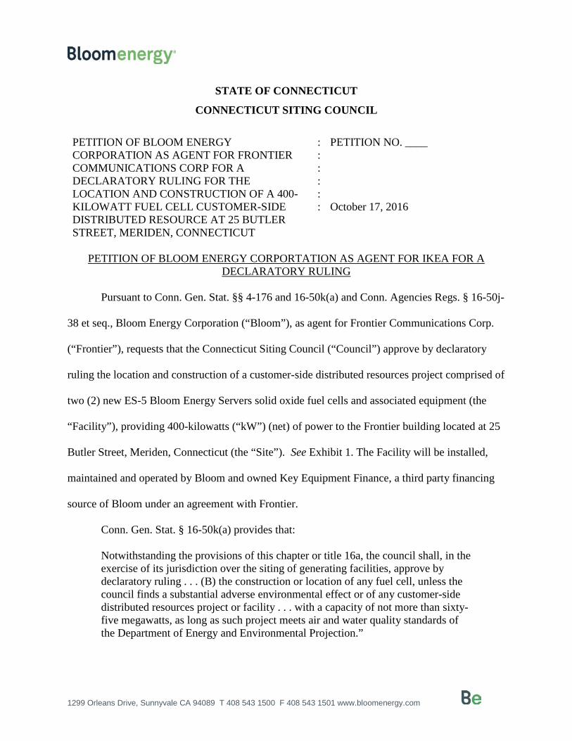
PETITION OF BLOOM ENERGY CORPORATION AS AGENT FOR FRONTIER COMMUNICATIONS CORP FOR A DECLARATORY RULING FOR THE LOCATION AND CONSTRUCTION OF A 400-KILOWATT FUEL CELL CUSTOMER-SIDE DISTRIBUTED RESOURCE AT 25 BUTLER STREET, MERIDEN, CONNECTICUT
: : : : : :
PETITION NO. ____ October 17, 2016
PETITION OF BLOOM ENERGY CORPORTATION AS AGENT FOR IKEA FOR A
DECLARATORY RULING
Pursuant to Conn. Gen. Stat. §§ 4-176 and 16-50k(a) and Conn. Agencies Regs. § 16-50j-
38 et seq., Bloom Energy Corporation (“Bloom”), as agent for Frontier Communications Corp.
(“Frontier”), requests that the Connecticut Siting Council (“Council”) approve by declaratory
ruling the location and construction of a customer-side distributed resources project comprised of
two (2) new ES-5 Bloom Energy Servers solid oxide fuel cells and associated equipment (the
“Facility”), providing 400-kilowatts (“kW”) (net) of power to the Frontier building located at 25
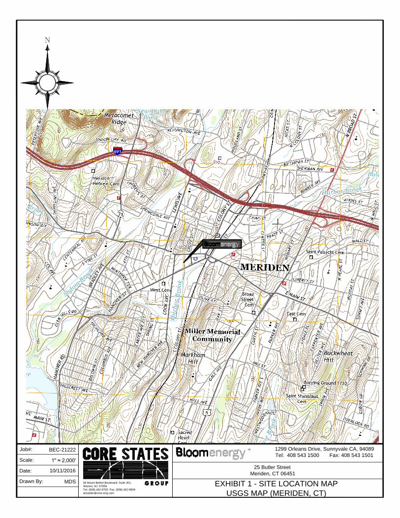
Butler Street, Meriden, Connecticut (the “Site”). See Exhibit 1. The Facility will be installed,
maintained and operated by Bloom and owned Key Equipment Finance, a third party financing
source of Bloom under an agreement with Frontier.
Conn. Gen. Stat. § 16-50k(a) provides that:
Notwithstanding the provisions of this chapter or title 16a, the council shall, in the exercise of its jurisdiction over the siting of generating facilities, approve by declaratory ruling . . . (B) the construction or location of any fuel cell, unless the council finds a substantial adverse environmental effect or of any customer-side distributed resources project or facility . . . with a capacity of not more than sixty-five megawatts, as long as such project meets air and water quality standards of the Department of Energy and Environmental Projection.”

1299 Orleans Drive, Sunnyvale CA 94089 T 408 543 1500 F 408 543 1501 www.bloomenergy.com
The proposed Facility will be a customer-side distributed resource facility under 65
megawatts (“MW”) that complies with the air and water quality standards of the Connecticut
Department of Energy and Environmental Protection (“DEEP”). Bloom submits that no
Certificate is required because the proposed modifications would not have a substantial adverse
environmental effect in the immediate vicinity of the Facility as well as in the State of
Connecticut.
I. COMMUNICATIONS
Correspondence and other communication regarding this petition should be directed to
the following parties:
Justin Adams Bloom Energy Corporation 1299 Orleans Drive Sunnyvale, CA 94089 Telephone: (860) 839-8373 Fax: (408) 543-1501 Email: [email protected]
Alicia Surowiec Bloom Energy Corporation 1299 Orleans Drive Sunnyvale, CA 94089 Telephone: (484) 888-3621 Fax: (408) 543-1501 Email: [email protected]
II. DISCUSSION
A. Project Description and Purpose
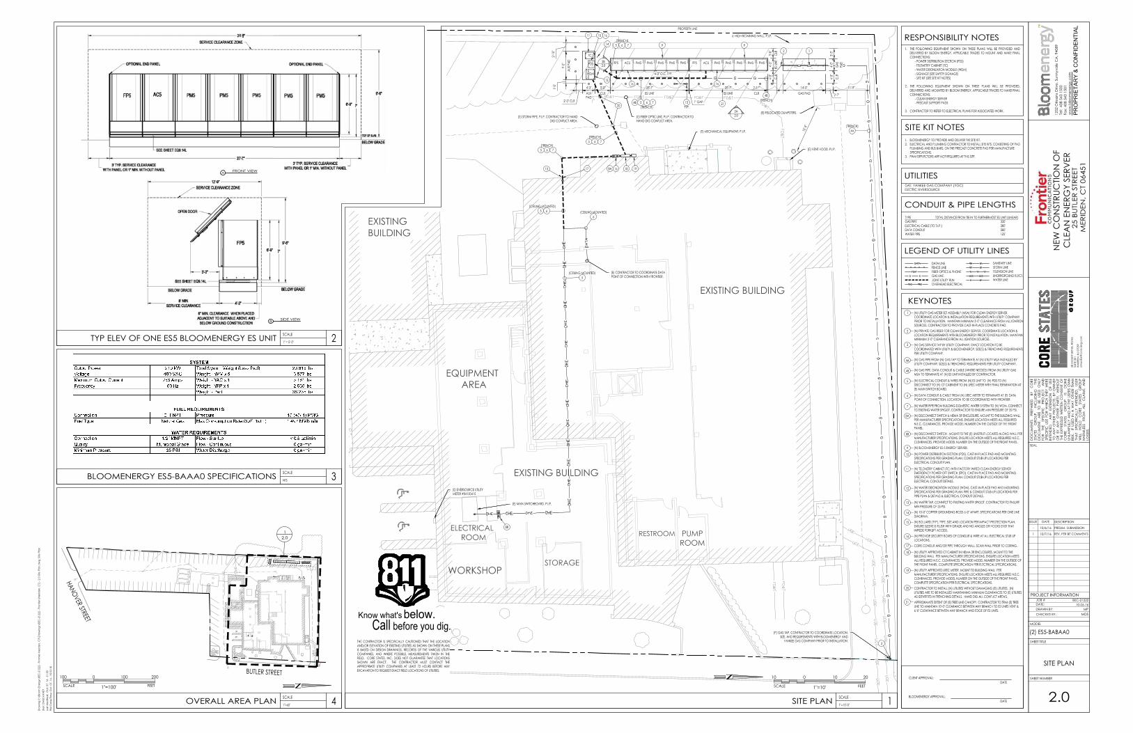
The Facility would be 400kW customer-side distributed resources consisting of two state-
of-the-art Bloom Energy Servers and associated equipment. The Facility will be interconnected
to the existing switchgear located inside the electrical room of the Frontier Communication Corp.
building (the “Building”). See Exhibit 2.
The Facility will be a “customer-side distributed resources” project because it will be “a
unit with a rating of not more than sixty-five megawatts [and is located] on the premises of an

1299 Orleans Drive, Sunnyvale CA 94089 T 408 543 1500 F 408 543 1501 www.bloomenergy.com
industrial end user within the transmission and distribution system including, but not limited to,
fuel cells . . . .” Conn. Gen. Stat. § 16-1(a)(40)(A). Further, in its Final Decision in Docket No.
12-02-09, dated September 12, 2012, the Connecticut Public Utilities Regulatory Authority
(“PURA”) determined that Bloom’s Energy Server qualifies as a Class I renewable energy
source fuel cell as defined in Conn. Gen. Stat. §16-1(a)(26)(A). See Exhibit 3.
The purpose of the proposed Facility is to replace the average baseload of the Building
with a Class I renewable energy source, achieve corporate sustainability goals, and improve
reliability of electrical systems and equipment. The meter interval data analysis conducted in
2016 (Exhibit 4) determined the average baseload for the Building to be 367kW, roughly
equivalent to the proposed 400kW Facility. Therefore, electricity generated by the Facility will
be consumed primarily at the Site, and any excess electricity will be exported to the grid.
B. The Facility
i. The Facility
The Facility will consist of two Bloom solid oxide fuel cell Energy Servers and
associated equipment. The dimensions of the Facility are approximately 70 feet long, 4 feet
wide and 7 feet high. The Energy Server module is enclosed, factory-assembled and tested prior
to installation on the Site. See Exhibit 5.
The Facility will be capable of producing 400 kW of continuous, reliable electric power.
The Facility will interconnect to the Site’s distribution system and operate in parallel with the
grid to provide the Site’s electrical requirements. Any electricity generated in excess of the Site’s
requirement will be exported to the grid under Eversource’s net metering tariff. This site will not
have an uninterruptible power module (“UPM”) and thus will not have any means to output
1299 Orleans Drive, Sunnyvale CA 94089 T 408 543 1500 F 408 543 1501 www.bloomenergy.com
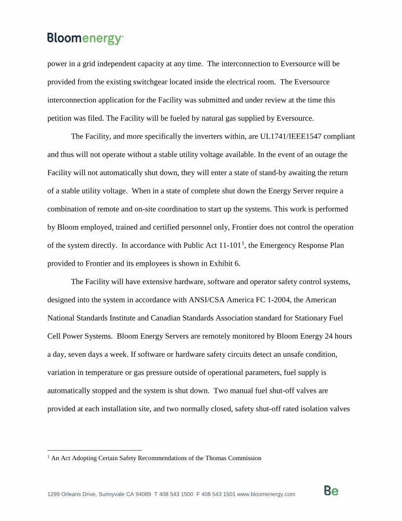
power in a grid independent capacity at any time. The interconnection to Eversource will be
provided from the existing switchgear located inside the electrical room. The Eversource
interconnection application for the Facility was submitted and under review at the time this
petition was filed. The Facility will be fueled by natural gas supplied by Eversource.
The Facility, and more specifically the inverters within, are UL1741/IEEE1547 compliant
and thus will not operate without a stable utility voltage available. In the event of an outage the
Facility will not automatically shut down, they will enter a state of stand-by awaiting the return
of a stable utility voltage. When in a state of complete shut down the Energy Server require a
combination of remote and on-site coordination to start up the systems. This work is performed
by Bloom employed, trained and certified personnel only, Frontier does not control the operation
of the system directly. In accordance with Public Act 11-1011, the Emergency Response Plan
provided to Frontier and its employees is shown in Exhibit 6.
The Facility will have extensive hardware, software and operator safety control systems,
designed into the system in accordance with ANSI/CSA America FC 1-2004, the American
National Standards Institute and Canadian Standards Association standard for Stationary Fuel
Cell Power Systems. Bloom Energy Servers are remotely monitored by Bloom Energy 24 hours
a day, seven days a week. If software or hardware safety circuits detect an unsafe condition,
variation in temperature or gas pressure outside of operational parameters, fuel supply is
automatically stopped and the system is shut down. Two manual fuel shut-off valves are
provided at each installation site, and two normally closed, safety shut-off rated isolation valves
1 An Act Adopting Certain Safety Recommendations of the Thomas Commission

1299 Orleans Drive, Sunnyvale CA 94089 T 408 543 1500 F 408 543 1501 www.bloomenergy.com
are installed within the system. In accordance with Public Act 11-1012, the fuel lines (pipe)
cleaning procedure are to purge for 60 seconds with 10 blasts of on off prior to connecting to the
Facility. The Facility will be installed in compliance with all applicable building, plumbing,
electrical, and fire codes.
Bloom Energy Servers are installed in accordance with NFPA 8533. This standard
provides fire prevention and fire protection requirements for safeguarding life and physical
property associated with buildings or facilities that employ stationary fuel cell systems of all
sizes. The risk of fire related to the operation of the Energy Server is therefore very low.
Furthermore, in the Energy Server, natural gas is not burned; it is used in a chemical reaction to
generate electricity. The natural gas is digested almost immediately upon entering the unit and is
no longer combustible. As stated above, any variation in heat outside of the operational
parameters will trigger an automatic shutdown of the energy server.
C. Existing Environment
i. The Site
The Facility would be installed within the Frontier property located at 25 Butler Street,
Meriden, Connecticut. Specifically, the Facility will be constructed on the 1.38-acre property
(“the Site”) that surrounds the Building. The Site is zoned as “Central Commercial” (“C-1”)
under the zoning regulations of the City of Meriden (the “City”).
2 Public Act 11-101, An Act Adopting Certain Safety Recommendations of the Thomas Commission, 3 Standard for the Installation of Stationary Fuel Cell Power Systems, 2015 Edition
1299 Orleans Drive, Sunnyvale CA 94089 T 408 543 1500 F 408 543 1501 www.bloomenergy.com
The majority of the surrounding areas are zoned under C-1, Central Commercial Design
District (“CCDD”) and Industrial (“M-3”). There are apartment complexes and a YMCA
abutting the Site to the west and north respectively.
The Facility would be located on a concrete pad within an existing paved driveway and
parking lot at the rear of the Building. The Building is over parked, which means there are more
parking spaces than required by the City of Meriden (“City”). At the conclusion of the project,
the Building will remain over parked. The location of Facility was strategically placed in
proximity to the existing mechanical equipment, at the rear of the Building, and adjacent to an
existing retaining wall to reduce visual impacts to the City and abutters. Panoramic photos of the
proposed location and adjacent areas are provided in Exhibit 7.
ii. Wildlife, Habitat and Cultural Resources
A review of the publically available Natural Diversity Database (NDDB) has shown no
known occurrences of state-listed species within the proposed Facility location. Furthermore, the
proposed Facility will be located on a driveway and parking area that were previously developed
and disturbed during construction of the Building. Therefore, the construction and operation of
the Facility will not have a substantial adverse effect on wetlands, state-listed species, and
cultural (archaeological and historical) resources.
iii. Flood Zones
A review of the flood hazard mapping data from Federal Emergency Management
Agency’s (“FEMA”) National Flood Insurance Program (“NFIP”) has shown the Facility would
be located within an unshaded FEMA Zone X, an area determined to be outside the 500‐year
flood and protected by levee from 100‐year flood. However, the southernmost portion of the
1299 Orleans Drive, Sunnyvale CA 94089 T 408 543 1500 F 408 543 1501 www.bloomenergy.com
Site is within the 100-year flood zone area of the Harbor Brook. See Exhibit 8. Site work, such
as grading and soil removal, would be limited to areas outside of the 100-year flood zone in the
northern portions of the Site.
D. Environmental Effects and Mitigation
i. Natural Gas Desulfurization Process
The first step in the production of electricity in the Bloom Energy server is
desulfurization – the removal of the sulfur compounds, which have been added to the natural gas
as an odorant by the natural gas suppliers. This step occurs in the desulfurization unit – a canister
which contains a filter made for this purpose. Sulfur is not “produced” in this process, but is
separated from the natural gas in which it was contained. In that process, trace levels of other
compounds which are naturally present in the natural gas may also absorb to the filter. Again,
these are not “produced” from the process, but are separated from the natural gas in which they
were contained. The filter is made up of inert materials.
The desulfurization process takes place entirely within desulfurization canisters. These
are made of extruded aluminum or zinc-plated steel that are built to last for the life of the Energy
Server and beyond. Because they are built to hold natural gas, their structural integrity is
essential. That integrity is assured by around the clock monitoring of the Energy Servers to
detect any leak. Were there a leak, the Server (including the desulfurization operation) would
shut down automatically. There has never been a leak from one of the desulfurization canisters.
The structural integrity and leak prevention continues after the desulfurization canisters are
removed from service. At that point, the entry and exit points for the natural gas automatically
seal shut. The desulfurization canister remains sealed and is not opened at the site, or anywhere

1299 Orleans Drive, Sunnyvale CA 94089 T 408 543 1500 F 408 543 1501 www.bloomenergy.com
in the State of Connecticut. In this respect, the Bloom system differs from other systems which
may have been reviewed by the Siting Council. Unlike the Bloom desulfurization canisters, other
desulfurization containers are emptied at the site of the fuel cell. At that point, the integrity of the
container is necessarily reduced and the applicable regulations change accordingly.
Within days that a desulfurization canister is taken out of service, it is picked up by a
Bloom contractor and taken to a licensed facility outside the State, where the desulfurization unit
is opened and the contents are removed. As described above, the desulfurization unit has
complete structural integrity. Its safety as a container for transporting has been certified by the
Department of Transportation (DOT). Specifically, the desulfurization containers are certified to
the standards set by DOT, the United Nations, IATA, ICAO and IMO as meeting Hazardous
Materials Distribution and Packaging requirements. This certification assures that the canisters
are secure and have the structural integrity to transport the desulfurization materials safely and
without risk of a release.
Bloom has been engaged and expect to have further follow up discussion with regulators
on the proper management of materials found in all public pipeline natural gas supplied to homes
and businesses, which we filter before that fuel is consumed by our product to produce clean,
environmentally friendly electric power. Because our technology is relatively new, the 35 year
old regulations do not address our situation, but we have been working with the regulators to
obtain clarification.
ii. Emissions
The construction and operation of the Facility will comply with DEEP’s air and water
quality standards and will not have a substantial adverse environmental effect.
1299 Orleans Drive, Sunnyvale CA 94089 T 408 543 1500 F 408 543 1501 www.bloomenergy.com
With respect to water discharges, the Energy Servers are designed to operate without
water discharge under normal operating conditions. Additionally, the Facility would use no
water during normal operation beyond a 240-gallon injection at start up.
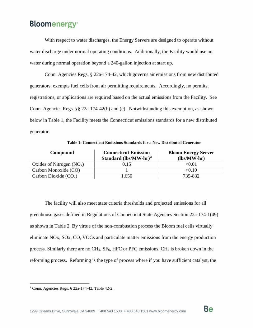
Conn. Agencies Regs. § 22a-174-42, which governs air emissions from new distributed
generators, exempts fuel cells from air permitting requirements. Accordingly, no permits,
registrations, or applications are required based on the actual emissions from the Facility. See
Conn. Agencies Regs. §§ 22a-174-42(b) and (e). Notwithstanding this exemption, as shown
below in Table 1, the Facility meets the Connecticut emissions standards for a new distributed
generator.
Table 1: Connecticut Emissions Standards for a New Distributed Generator
Compound Connecticut Emission Standard (lbs/MW-hr)4
Bloom Energy Server (lbs/MW-hr)
Oxides of Nitrogen (NOx) 0.15 <0.01 Carbon Monoxide (CO) 1 <0.10 Carbon Dioxide (CO2) 1,650 735-832
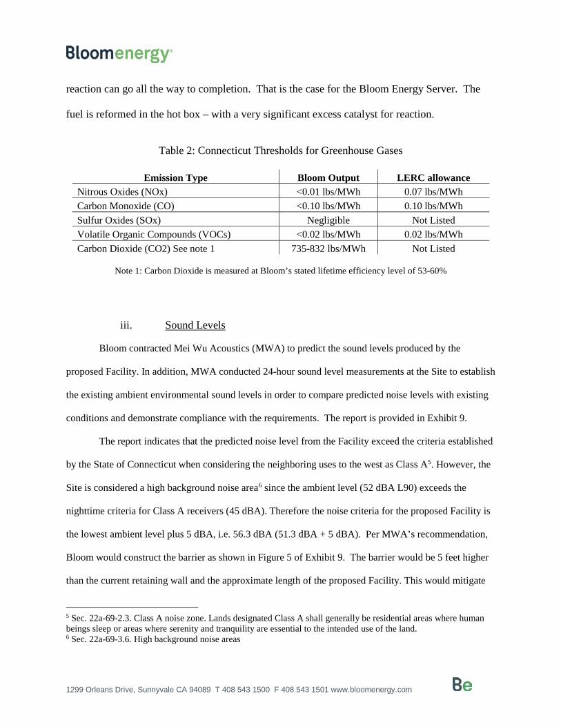
The facility will also meet state criteria thresholds and projected emissions for all
greenhouse gases defined in Regulations of Connecticut State Agencies Section 22a-174-1(49)
as shown in Table 2. By virtue of the non-combustion process the Bloom fuel cells virtually
eliminate NOx, SOx, CO, VOCs and particulate matter emissions from the energy production
process. Similarly there are no CH4, SF6, HFC or PFC emissions. CH4 is broken down in the
reforming process. Reforming is the type of process where if you have sufficient catalyst, the
4 Conn. Agencies Regs. § 22a-174-42, Table 42-2.
1299 Orleans Drive, Sunnyvale CA 94089 T 408 543 1500 F 408 543 1501 www.bloomenergy.com
reaction can go all the way to completion. That is the case for the Bloom Energy Server. The
fuel is reformed in the hot box – with a very significant excess catalyst for reaction.
Table 2: Connecticut Thresholds for Greenhouse Gases
Emission Type Bloom Output LERC allowance Nitrous Oxides (NOx) <0.01 lbs/MWh 0.07 lbs/MWh Carbon Monoxide (CO) <0.10 lbs/MWh 0.10 lbs/MWh Sulfur Oxides (SOx) Negligible Not Listed Volatile Organic Compounds (VOCs) <0.02 lbs/MWh 0.02 lbs/MWh Carbon Dioxide (CO2) See note 1 735-832 lbs/MWh Not Listed
Note 1: Carbon Dioxide is measured at Bloom’s stated lifetime efficiency level of 53-60%
iii. Sound Levels
Bloom contracted Mei Wu Acoustics (MWA) to predict the sound levels produced by the
proposed Facility. In addition, MWA conducted 24-hour sound level measurements at the Site to establish
the existing ambient environmental sound levels in order to compare predicted noise levels with existing
conditions and demonstrate compliance with the requirements. The report is provided in Exhibit 9.
The report indicates that the predicted noise level from the Facility exceed the criteria established
by the State of Connecticut when considering the neighboring uses to the west as Class A5. However, the
Site is considered a high background noise area6 since the ambient level (52 dBA L90) exceeds the
nighttime criteria for Class A receivers (45 dBA). Therefore the noise criteria for the proposed Facility is
the lowest ambient level plus 5 dBA, i.e. 56.3 dBA (51.3 dBA + 5 dBA). Per MWA’s recommendation,
Bloom would construct the barrier as shown in Figure 5 of Exhibit 9. The barrier would be 5 feet higher
than the current retaining wall and the approximate length of the proposed Facility. This would mitigate
5 Sec. 22a-69-2.3. Class A noise zone. Lands designated Class A shall generally be residential areas where human beings sleep or areas where serenity and tranquility are essential to the intended use of the land. 6 Sec. 22a-69-3.6. High background noise areas
1299 Orleans Drive, Sunnyvale CA 94089 T 408 543 1500 F 408 543 1501 www.bloomenergy.com
the expected noise levels at the nearest sensitive receptors to be compliant with the State of Connecticut
regulations for the Control of Noise.
iv. Visual Effects
The overall visual effect would be mitigated by the proposed location at the rear of the
Building, adjacent to an existing retaining wall, and in proximity to existing mechanical
equipment.
E. Project Construction and Maintenance
During construction, appropriate erosion and sedimentation (E&S) controls will be
installed and areas of disturbance will be promptly stabilized in order to minimize the potential
for soil erosion and the flow of sediments off site or into the nearby flood zone and Harbor
Brook. Temporary E&S control measures will be maintained and inspected throughout
construction to ensure their integrity and effectiveness. The temporary E&S control measures
will remain in place until the work is complete and all disturbed areas have been stabilized.
Ground disturbance, such as grading and soil removal, would be limited to areas outside of the
100-year flood zone. Construction equipment and materials will be staged outside of the flood
zone. Due to the limited disturbance required for the Facility’s installation, no construction-
related storm water permits will be required. Further, no additional impervious area will be
added to the Site and it will not affect drainage patterns or stormwater discharge.
Construction-related impacts will be minimal. The Facility will be located within an
existing asphalt area behind the Building. The facility will not extend beyond the limits of the

1299 Orleans Drive, Sunnyvale CA 94089 T 408 543 1500 F 408 543 1501 www.bloomenergy.com
existing asphalt area. All utilities will be installed within the asphalt area and along the rear face
of the Building. All utility trenches will be restored in-kind.
III. COMMUNITY OUTREACH
Bloom has provided notice of this petition to all persons and appropriate municipal
officials and governmental agencies to whom notice is required to be given pursuant to Conn.
Agencies Regs. § 16-50j-40(a).7 A copy of the notice letter and a service list are provided in
Exhibit 9 and the corresponding abutters map is provided in Exhibit 11. Additionally, prior to
filing this petition, representatives from Bloom briefly discussed the proposed Facility with Paul
Dickson from the City of Meriden Planning Department. An opportunity to comment on the
proposed Site Plan has been provided to the Mayor and City Planner to incorporate any design
comments they may have. See Exhibit 12.
IV. BASIS FOR GRANTING OF THE PETITION
Under Conn. Gen. Stat. § 16-50k(a), the Council is required to approve by declaratory
ruling the construction or location of a customer-side distributed resources project or facility
with a capacity of not more than 65 MW, as long as the facility meets DEEP air and water
quality standards. The proposed Facility meets each of these criteria. The Facility is a
“customer-side distributed resources” project, as defined in Conn. Gen. Stat. § 16-1(a)(40)(A),
because the Facility is “a unit with a rating of not more than sixty-five megawatts [and is
7 Conn. Agencies Regs. § 16-50j-40(a) requires that “[p]rior to submitting a petition for a declaratory ruling to the Council, the petitioner shall, where applicable, provide notice to each person other than the petitioner appearing of record as an owner of property which abuts the proposed primary or alternative sites of the proposed facility, each person appearing of record as an owner of the property or properties on which the primary or alternative proposed facility is to be located, and the appropriate municipal officials and government agencies [listed in Section 16-50l of the Connecticut General Statutes].”

1299 Orleans Drive, Sunnyvale CA 94089 T 408 543 1500 F 408 543 1501 www.bloomenergy.com
located] on the premises of a retail end user within the transmission and distribution system
including, but not limited to, fuel cells” and, as demonstrated herein, will meet DEEP air and
water quality standards. In addition, as demonstrated above, the construction and operation of
the Facility will not have a substantial adverse environmental effect in the State of Connecticut.
V. CONCLUSION
For the reasons stated above, Bloom, as agent for Frontier, respectfully requests that the
Council approve the location and construction of the Facility by declaratory ruling.
Respectfully submitted, Bloom Energy Corporation By: ____________________________
Justin Adams Bloom Energy Corporation 1299 Orleans Drive Sunnyvale, CA 94089 Telephone: (408) 338-7452 Email: [email protected]

1299 Orleans Drive, Sunnyvale CA 94089 T 408 543 1500 F 408 543 1501 www.bloomenergy.com
EXHIBITS
Exhibit 1: Site Location Map
Exhibit 2: Site Plan
Exhibit 3: Final Decision, PURA Docket No. 12-02-09, Petition of Bloom Energy Corporation for a Declaratory Ruling that Its Solid Oxide Fuel Cell Energy Server Will Qualify as a Class I Renewable Energy Source (Sept. 12, 2012)
Exhibit 4: Meter interval data analysis conducted in 2016
Exhibit 5: Bloom Energy Server Product Datasheet and General Installation Overview
Exhibit 6: Emergency Response Plan
Exhibit 7: Panoramic photos of the proposed location
Exhibit 8: FEMA Flood Map
Exhibit 9: Sound Analysis
Exhibit 10: Notice Pursuant to Conn. Agencies Regs. § 16-50j-40(a)
Exhibit 11: Abutters Map
Exhibit 12: Letters of Notice to Abutters, Mayor and City Planner

1299 Orleans Drive, Sunnyvale CA 94089 T 408 543 1500 F 408 543 1501 www.bloomenergy.com
Exhibit 1
1" ≈ 2,000'
EXHIBIT 1 - SITE LOCATION MAP
USGS MAP (MERIDEN, CT)
Job#:
Drawn By:
Date:
Scale:
10/11/2016
58 Mount Bethel Boulevard, Suite 301,
Warren, NJ 07059
Tel: (908) 462-9700 Fax: (908) 462-9909
MDS
BEC-21222
25 Butler Street
Meriden, CT 06451
TM
1299 Orleans Drive, Sunnyvale CA, 94089
Tel: 408 543 1500 Fax: 408 543 1501
1299 Orleans Drive, Sunnyvale CA 94089 T 408 543 1500 F 408 543 1501 www.bloomenergy.com
Exhibit 2

1299 Orleans Drive, Sunnyvale CA 94089 T 408 543 1500 F 408 543 1501 www.bloomenergy.com
Exhibit 3

STATE OF CONNECTICUT
DEPARTMENT OF ENERGY AND ENVIRONMENTAL PROTECTION PUBLIC UTILITIES REGULATORY AUTHORITY
TEN FRANKLIN SQUARE NEW BRITAIN, CT 06051
DOCKET NO. 12-02-09 PETITION OF BLOOM ENERGY CORPORATION FOR A DECLARATORY RULING THAT ITS SOLID OXIDE FUEL CELL ENERGY SERVER WILL QUALIFY AS A CLASS I RENEWABLE ENERGY SOURCE
September 12, 2012
By the following Directors:
Arthur H. House John W. Betkoski, III
DECISION I. INTRODUCTION By Petition dated February 14, 2012, pursuant to Section 4-176 in the General Statutes of Connecticut (Conn. Gen. Stat.) and Section 16-1-113 in the Regulations of Connecticut State Agencies, Bloom Energy Corporation requests that the Public Utilities Regulatory Authority (Authority) issue a declaratory ruling that its solid oxide fuel cell energy server qualifies as a Class I renewable energy source.
Docket No. 12-02-09 Page 2
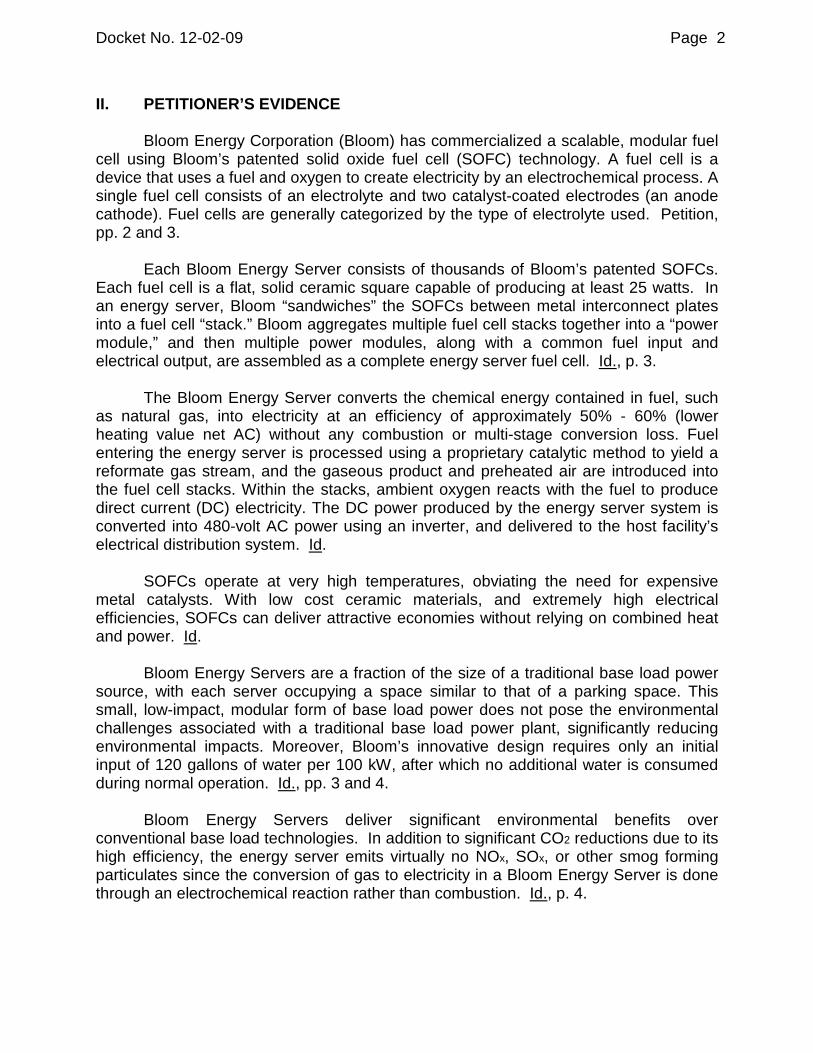
II. PETITIONER’S EVIDENCE
Bloom Energy Corporation (Bloom) has commercialized a scalable, modular fuel cell using Bloom’s patented solid oxide fuel cell (SOFC) technology. A fuel cell is a device that uses a fuel and oxygen to create electricity by an electrochemical process. A single fuel cell consists of an electrolyte and two catalyst-coated electrodes (an anode cathode). Fuel cells are generally categorized by the type of electrolyte used. Petition, pp. 2 and 3.
Each Bloom Energy Server consists of thousands of Bloom’s patented SOFCs.
Each fuel cell is a flat, solid ceramic square capable of producing at least 25 watts. In an energy server, Bloom “sandwiches” the SOFCs between metal interconnect plates into a fuel cell “stack.” Bloom aggregates multiple fuel cell stacks together into a “power module,” and then multiple power modules, along with a common fuel input and electrical output, are assembled as a complete energy server fuel cell. Id., p. 3.
The Bloom Energy Server converts the chemical energy contained in fuel, such
as natural gas, into electricity at an efficiency of approximately 50% - 60% (lower heating value net AC) without any combustion or multi-stage conversion loss. Fuel entering the energy server is processed using a proprietary catalytic method to yield a reformate gas stream, and the gaseous product and preheated air are introduced into the fuel cell stacks. Within the stacks, ambient oxygen reacts with the fuel to produce direct current (DC) electricity. The DC power produced by the energy server system is converted into 480-volt AC power using an inverter, and delivered to the host facility’s electrical distribution system. Id.
SOFCs operate at very high temperatures, obviating the need for expensive
metal catalysts. With low cost ceramic materials, and extremely high electrical efficiencies, SOFCs can deliver attractive economies without relying on combined heat and power. Id.
Bloom Energy Servers are a fraction of the size of a traditional base load power
source, with each server occupying a space similar to that of a parking space. This small, low-impact, modular form of base load power does not pose the environmental challenges associated with a traditional base load power plant, significantly reducing environmental impacts. Moreover, Bloom’s innovative design requires only an initial input of 120 gallons of water per 100 kW, after which no additional water is consumed during normal operation. Id., pp. 3 and 4.
Bloom Energy Servers deliver significant environmental benefits over
conventional base load technologies. In addition to significant CO2 reductions due to its high efficiency, the energy server emits virtually no NOx, SOx, or other smog forming particulates since the conversion of gas to electricity in a Bloom Energy Server is done through an electrochemical reaction rather than combustion. Id., p. 4.

Docket No. 12-02-09 Page 3
III. AUTHORITY ANALYSIS Conn. Gen. Stat. §16-1(a)(26) defines a Class I renewable energy source as:
(A) energy derived from solar power; wind power; a fuel cell; methane gas from landfills; ocean thermal power; wave or tidal power; low emission advanced renewable energy conversion technologies; a run-of-the-river hydropower facility provided such facility has a generating capacity of not more than five megawatts, does not cause an appreciable change in the river flow, and began operation after the effective date of this section; or a biomass facility, including, but not limited to, a biomass gasification plant that utilizes land clearing debris, tree stumps or other biomass that regenerates or the use of which will not result in a depletion of resources, provided such biomass is cultivated and harvested in a sustainable manner and the average emission rate for such facility is equal to or less than .075 pounds of nitrogen oxides per million BTU of heat input for the previous calendar quarter, except that energy derived from a biomass facility with a capacity of less than five hundred kilowatts that began construction before July 1, 2003, may be considered a Class I renewable energy source, provided such biomass is cultivated and harvested in a sustainable manner; or (B) any electrical generation, including distributed generation, generated from a Class I renewable energy source.
Based on Bloom’s assertions, the Authority finds that its Bloom Energy Server qualifies as a Class I renewable energy source “fuel cell” as defined in Conn. Gen. Stat. §16-1(a)(26)(A).
The Authority has created an electronic application process for generation
owners to apply for a Connecticut Renewable Portfolio Standards registration. The application is available on the Authority’s website at the web address http://www.ct.gov/pura . The application should be submitted electronically along with a single hard-copy filing. While the Authority concludes in this Decision that the Bloom Energy Server would qualify as a Class I renewable energy source pursuant to Conn. Gen. Stat. §16-1(a)(26), Bloom must still apply for registration of the aforementioned system once the facility becomes operational and is registered in the New England Generation Information System.
Docket No. 12-02-09 Page 4
IV. CONCLUSION
Based upon the project as described herein, the Authority finds that, as proposed, the Bloom Energy Server would qualify as a Class I renewable energy source. However, since the energy server is not yet operational, it should apply for Class I registration once it begins operations.
The Connecticut Department of Energy and Environmen tal Protection is an Affirmative Action/Equal Opportunity Employer that is committed to requirements of the Americans with Disabilities Act. Any person with a disability who may need information in an alternative format may conta ct the agency’s ADA Coordinator at 860-424-3194, or at [email protected] v. Any person with limited proficiency in English, who may need information in another language, may contact the agency’s Title VI Coordinator at 860-42 4-3035, or at [email protected]. Any person with a hearing im pairment may call the State of Connecticut relay number – 711. Discrimination complaints may be filed with DEEP’s Title VI Coordinator. Requests for accommod ations must be made at least two weeks prior to any agency hearing, progra m or event .

DOCKET NO. 12-02-09 PETITION OF BLOOM ENERGY CORPORATION FOR A DECLARATORY RULING THAT ITS SOLID OXIDE FUEL CELL ENERGY SERVER WILL QUALIFY AS A CLASS I RENEWABLE ENERGY SOURCE
This Decision is adopted by the following Directors:
Arthur H. House John W. Betkoski, III
CERTIFICATE OF SERVICE
The foregoing is a true and correct copy of the Decision issued by the Public Utilities Regulatory Authority, State of Connecticut, and was forwarded by Certified Mail to all parties of record in this proceeding on the date indicated.
September 12, 2012
Kimberley J. Santopietro Date Executive Secretary Department of Energy and Environmental Protection Public Utilities Regulatory Authority
60906902 V1-WORKSITEUS-029819/0002

1299 Orleans Drive, Sunnyvale CA 94089 T 408 543 1500 F 408 543 1501 www.bloomenergy.com
Exhibit 4
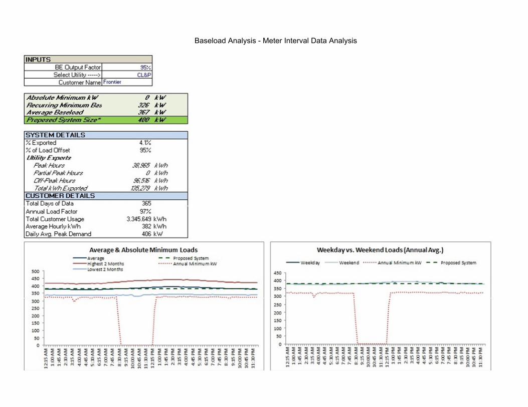
Baseload Analysis - Meter Interval Data Analysis

1299 Orleans Drive, Sunnyvale CA 94089 T 408 543 1500 F 408 543 1501 www.bloomenergy.com
Exhibit 5

CLEAN, RELIABLE POWER ON DEMANDThe Energy Server 5 delivers clean power that reduces emissions and energy costs. The modular architecture enables the installation to be tailored to the actual electricity demand, with a flexibility to add servers as the load increases. The Energy Server 5 actively communicates with Bloom Energy’s network operations centers so system performance can be monitored 24 hours per day, 365 days per year.
INNOVATIVE TECHNOLOGYUtilizing solid oxide fuel cell (SOFC) technology first developed for NASA’s Mars program, the Energy Server 5 produces clean power at unprecedented efficiencies, meaning it consumes less fuel and produces less CO2 than competing technologies. Additionally, no water is needed under normal operating conditions.
ALL-ELECTRIC POWERThe Energy Server 5, which operates at a very high electrical efficiency, eliminates the need for complicated and costly CHP systems. Combining the standard electrical and fuel connections along with a small footprint and sleek design, the Energy Server 5 is the most deployable fuel cell solution on the market.
CONTROLLED AND PREDICTABLE COSTBy providing efficient on-site power generation, the economic and environmental benefits are central to the Energy Server 5 value proposition. Bloom Energy customers can lock in their long term energy costs and mitigate the risk of electricity rate increases. The Energy Server 5 has been designed in compliance with a variety of safety standards and is backed by a comprehensive warranty.
Clean, Reliable, Affordable Energy
PRODUCT DATASHEET
Energy Server 5
About Bloom Energy Bloom Energy is making clean, reliable energy affordable. Our unique on-site power generation systems utilize an innovative fuel cell technology with roots in NASA’s Mars program. By leveraging breakthrough advances in materials science, Bloom Energy systems are among the most efficient energy generators, providing for significantly reduced operating costs and dramatically lower greenhouse gas emissions. Bloom Energy Servers are currently producing power for many Fortune 500 companies including Apple, Google, NSA, Walmart, AT&T, eBay, Staples, as well as notable non-profit organizations such as Caltech and Kaiser Permanente.
Headquarters:Sunnyvale, California
For More Information:www.bloomenergy.com

Energy Server 5
© Bloom Energy Corporation 2016. All Rights Reserved. DOC-1005705. Rev. C
Bloom Energy Corporation 1299 Orleans Drive Sunnyvale CA 94089 T 408 543 1500 www.bloomenergy.com
Technical Highlights (ES5-AA1AA0)
Outputs
Nameplate power output (net AC) 262.5 kW
Base load output (net AC) 250 kW
Electrical connection 480 V, 3-phase, 60 Hz
Inputs
Fuels Natural gas, directed biogas
Input fuel pressure 10-18 psig (15 psig nominal)
Water None during normal operation
Efficiency
Cumulative electrical efficiency (LHV net AC)* 65-53%
Heat rate (HHV) 5,811-7,127 Btu/kWh
Emissions
NOx < 0.01 lbs/MWh
SOx Negligible
CO <0.05 lbs/MWh
VOCs < 0.02 lbs/MWh
CO2 @ stated efficiency 679-833 lbs/MWh on natural gas;
carbon neutral on directed biogas
Physical Attributes and Environment
Weight 14.3 tons
Dimensions (variable layouts) 14'9" x 8'9" x 7' or 29'6" x 4'5" x 7'5"
Temperature range -20° to 45° C
Humidity 0% - 100%
Seismic vibration IBC site class D
Location Outdoor
Noise < 70 dBA @ 6 feet
Codes and Standards
Complies with Rule 21 interconnection and IEEE1547 standards
Exempt from CA Air District permitting; meets stringent CARB 2007 emissions standards
Product Listed by Underwriters Laboratories Inc. (UL) to ANSI/CSA FC 1-2014
Additional Notes
Access to a secure website to monitor system performance & environmental benefits
Remotely managed and monitored by Bloom Energy
Capable of emergency stop based on input from the site
* 65% LHV efficiency verified by ASME PTC 50 Fuel Cell Power Systems Performance Test

Bloom Energy Server
Page 1 |


Bloom Energy Server Installation
Page 3 |
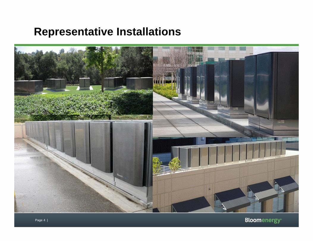
Page 4 |
Representative Installations

1299 Orleans Drive, Sunnyvale CA 94089 T 408 543 1500 F 408 543 1501 www.bloomenergy.com
Exhibit 6

Fire Prevention and Emergency Planning
Page 2 of 12
Copyright © 2011. Unpublished Work of Bloom Energy. All Rights Reserved. This work is an unpublished work and contains confidential, proprietary, and trade secret information of Bloom Energy. No part of this work may be practiced, performed, copied, distributed, revised, modified, translated, abridged, condensed, expanded, collected, or adapted without the prior written consent of Bloom Energy. Any use or exploitation of this work without authorization could subject the perpetrator to criminal and civil liability.
Bloom Energy Corporation, 1299 Orleans Drive, Sunnyvale, CA 94089 USA

Page 3 of 12
Table of Contents
1. Fire Prevention and Emergency Planning Overview
2. Fuel Cell Installation Safety Features
3. Emergency Notification Procedures
4. Fire and Smoke Procedures
5. Medical Emergency Procedures
6. Materials Release Procedures
7. Natural Disasters and Severe Weather7.1 Earthquake7.2 Flood
8. Utility Outage
9. Good Housekeeping and Maintenance9.1 Good Housekeeping9.2 Maintenance
10. Training
Page 4 of 12
1. FIRE PREVENTION AND EMERGENCY PLANNING OVERVIEW
The following document is provided only as a guide to assist you in complying with national and local codes and requirements, as well as to provide other helpful information. It is not intended to supersede the requirements of any standard. You should review the standards for particular requirements that are applicable to your individual situation, and make adjustments to this program that are specific to your company. You will need to add information relevant to your facility in order to develop an effective, comprehensive program.
2. FUEL CELL SYSTEM INSTALLATION SAFETY FEATURES
The fuel cell system has redundant safety features and in-system checks to ensure that the system will not harm certified technicians or bystanders near the unit. While the actual fuel cells operate at high temperatures, these components do not move, and are contained within many layers of insulation. During normal operation, the unit is cool to the touch and operates quietly.
The fuel cell system is controlled electronically and has internal sensors that continuously measure system operation. If safety circuits detect a condition outside normal operating parameters, the fuel supply is stopped and individual system components are automatically shut down. A Bloom Energy Remote Monitoring and Control Center (RMCC) operator can also remotely initiate any emergency sequence. An Emergency Stop alarm condition initiates an automatic shutdown sequence that puts the fuel cell system into ―safe mode‖ and causes it to stop exporting power. If you have questions about any of these safety features, please contact Bloom Energy.
If you have to shut down your fuel cell system right away—for example, in case of a building fire or electrical hazard—three shutoff controls are installed at your facility external to the system. The locations of these three controls should be known to your facilities manager before operation, and should be noted on your facility diagram that
you created with your Bloom Energy account manager. The three shutoffs are the EPO
button, the electrical disconnect, and the natural gas shutoff valve.
An Emergency Power Off (EPO) Button cuts all power to all systems and stops them from exporting power to your building. All natural gas flow is also stopped within the systems. (The EPO button is on the front/side of the EDM, if an EDM is installed.) Lift the protective cover and break the glass seal that covers the button with the attached hammer. After the glass seal is broken, the shutdown sequence will automatically begin.
Page 5 of 12
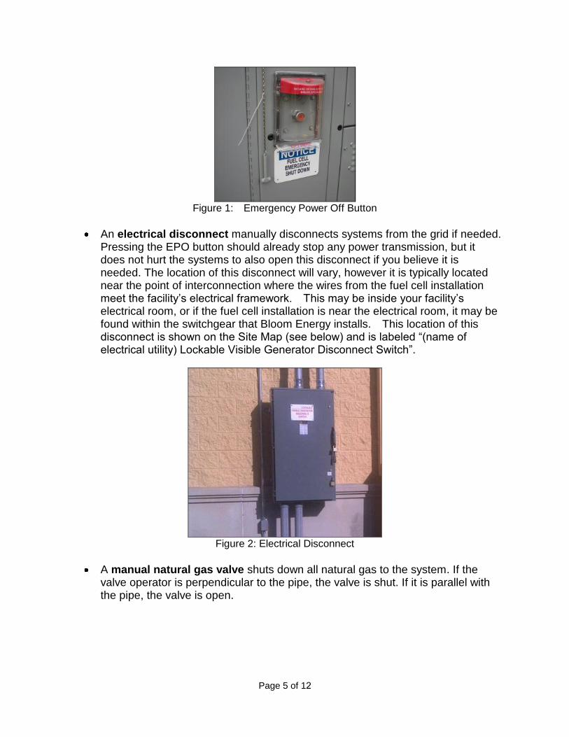
Figure 1: Emergency Power Off Button
An electrical disconnect manually disconnects systems from the grid if needed. Pressing the EPO button should already stop any power transmission, but it does not hurt the systems to also open this disconnect if you believe it is needed. The location of this disconnect will vary, however it is typically located near the point of interconnection where the wires from the fuel cell installation meet the facility’s electrical framework. This may be inside your facility’s electrical room, or if the fuel cell installation is near the electrical room, it may be found within the switchgear that Bloom Energy installs. This location of this disconnect is shown on the Site Map (see below) and is labeled ―(name of electrical utility) Lockable Visible Generator Disconnect Switch‖.
Figure 2: Electrical Disconnect
A manual natural gas valve shuts down all natural gas to the system. If the valve operator is perpendicular to the pipe, the valve is shut. If it is parallel with the pipe, the valve is open.

Page 6 of 12
Figure 3: Manual Natural Gas Valve
Site map: • An overhead site map showing the location of all safety features will be posted
throughout the fuel cell installation• Electronic copies are available to you for use in your site planning
Figure 4: Sample Site Map
Manual controls: • Clearly marked emergency stop button labeled ―Fuel Cell Emergency Shut
Down‖ located at site• Two manual fuel shutoff valves outside the system, and two isolation valves
inside the system
Fire hazard mitigation: • System is plumbed directly to utility-provided natural gas• If system input gas pressure is compromised, a pressure switch triggers an
emergency system shutdown and fuel input is isolated• System does not use fuel compressors or pumps• System has virtually no stored fuel (internal capacity is < 5 scf)
Electrical hazard and mitigation:
Page 7 of 12
• System operates at 480V• Signs inside the system warn of the risk of electric shock• System has backfeed protection• System inverter prevents grid backfeed during a power outage
Mechanical hazard and mitigation: • Finger/hand guard protection is provided on all fans• All moving parts are located behind secured doors
Material hazard mitigation:• Desulfurizer bed (to remove fuel impurities) are fully enclosed• Maintained and serviced by licensed vendors
3. EMERGENCY NOTIFICATION PROCEDURES
Life-Threatening Emergencies To report life-threatening emergencies, immediately call:
Fire: 911
Ambulance: 911
Police: 911
Conditions that require automatic emergency notification include: • Unconscious Victim• Seizure• Major Trauma• Chest Pains• Difficulty Breathing• Flames
Non-Life-Threatening Emergencies For non-life-threatening emergencies, report the incident to the local safety control center.
When you report an emergency, give the following information: • Exact nature of the emergency (describe as clearly and accurately as possible).• Exact location (i.e., address, building, floor, area, department, etc.).• Telephone number from which you are calling.• Your full name.• Do not hang up, as additional information may be needed.
To assist in any subsequent investigation or determination of corrective actions, it is recommended to record the following items as close to the incident time as possible:
• Summary of any violation

Page 8 of 12
• Identification of responsible parties• Identification of victims and witnesses• Description of evidence• Description of general conditions• Description of any vehicles involved• Narratives from witnesses• Any photographs
4. FIRE OR SMOKE PROCEDURES
This section describes the procedures involving a fire or smoke. A major fire is one that requires the use of more than one fire extinguisher or takes more than one minute to extinguish.
If you discover a fire or smoke:
1. Activate the nearest fire alarm if not activated already.2. Activate the fuel cell Emergency Stop if possible.3. Shut off the fuel cell installation natural gas line if possible.4. If the fire is small and does not pose an immediate risk to personal safety, you may
attempt to extinguish it with a portable fire extinguisher only if trained to do so.5. Avoid using water on electrical fires.6. Report every fire, regardless of size, immediately. Smoke or the smell of smoke
should be reported.
• From a safe location dial 911.• Report the incident to the local security safety center.
5. MEDICAL EMERGENCY PROCEDURES
This section describes the necessary procedures for injuries or illnesses that may occur under extreme conditions.
A serious injury can be life-threatening and will require immediate medical attention. Injuries can include head injuries, spine injuries, broken bones, heart attack, stroke, loss of consciousness, excessive bleeding, chemical exposure, etc.
A non-serious injury is not immediately life-threatening but may still require the attention of a medical doctor. These can include headaches, nausea, itching, cuts, burns, etc.
Life-Threatening Medical Emergency 1. Remain calm.2. Immediately dial 911.3. Report the incident to local security safety center.4. Do not move the victim unless it is absolutely necessary.5. Call out for personnel trained in first aid and/or CPR which may include Building
Evacuation or Emergency Response team members.

Page 9 of 12
6. Ask someone to bring the area first aid kit and Automated External Defibrillator.7. Assist if capable or asked to do so.
Non-Life-Threatening Medical Emergency 1. Remain calm.2. Report the incident to the local security safety center.3. Do not move the victim unless it is absolutely necessary.4. Call out for personnel trained in first aid.5. Ask someone to bring the area first aid kit.6. If the victim requires further medical attention, then direct them to the nearest
approved medical clinic or hospital – Contact Security or Human Resources forassistance if needed.
7. The injured employee’s supervisor/manager is responsible for ensuring injury formsare properly filled out. Complete the forms within 24 hours of incident and submitto the injury reporting system for follow-up. Follow company protocols.
6. MATERIALS RELEASE PROCEDURES
The fuel cell system does not pose a hazard to health or environment. However,some internal materials when released, may pose a irritation risk to people and a possible risk of fire if not properly handled. This section was designed to addresspotential material release events:
In case of a material release that poses a direct threat to health, safety, or theenvironment:
1. Report the incident to local safety/security office.
2. If extremely life-threatening immediately dial 911 followed with a call to Security.3. Contain the spill.4. Evacuate the area or building if the material release is determined to be life-
threatening.
In the event of an unknown indoor smell or odor, report the incident to authorities responsible for HAZMAT and spills.
7. NATURAL DISASTERS AND SEVERE WEATHER
7.1 Earthquake
This section provides information and procedures for earthquake emergencies.
The fuel cell system is designed to automatically shut off if the natural gas supply is compromised.
The natural gas supply line has an external, manual shut-off valve that should be activated if it is safe to do so. This valve will be labeled, ―Notice – Fuel Cell Gas Shut

Page 10 of 12
Off‖. The natural gas line will be labeled with the word ―gas‖ on a yellow background with an arrow pointing in the direction of flow.
The nearby Emergency Stop can be activated to stop the flow of fuel and power to/from the fuel cell system.
A Bloom Energy Field Engineer will validate site safety and system operation during/after severe weather as necessary.
7.2 Flood
The fuel cell system support pad is designed to divert water flow. However, if flooding conditions exist, or threaten to exist due to heavy rainfall, creek bank overflows, or pipe breakage, then immediately report the incident to the local safety/security office.
Do not use the fuel cell power system if any part has been under water. If it is safe to reach the Emergency Power Off button for the site without entering the water, stop all systems until a Bloom Energy representative can assess the site.
Precautions to follow after a flood:
• Stay out of flooded areas. Flooded areas remain unsafe. Entering a floodedarea places you at risk.
• Notify Bloom Energy. A Bloom Energy Field Engineer will validate site safetyand system operation during/after severe weather as necessary
8. UTILITY OUTAGE
The fuel cell system is operated in ―Grid-Parallel‖ mode. If utility provided power is lost for any reason, the fuel cell system will go ―off-line‖. The fuel cell system will remain in stand-by mode until it automatically senses the utility grid has been restored. If utility gas is shut down, the fuel cell system will begin to shut down completely.
The Bloom Energy Remote Monitoring Control Centers monitor the fuel cells 24 hours per day and will be alerted to utility grid interruptions via its controls software. A Field Service Engineer will be dispatched to restart the fuel cell system if necessary. Customer personnel should NOT attempt to start up or operate the fuel cell system.
Before a Planned Outage
• Notify the Bloom Energy Remote Monitoring Control Center at 1-408-543-1678at least 24 hours before planned outage.
• Bloom Energy Remote Monitoring Engineers will reduce power generated by thefuel cell system and take the fuel cell off-line.
• Abrupt fuel cell system shutdowns may cause significant system damage.
Page 11 of 12
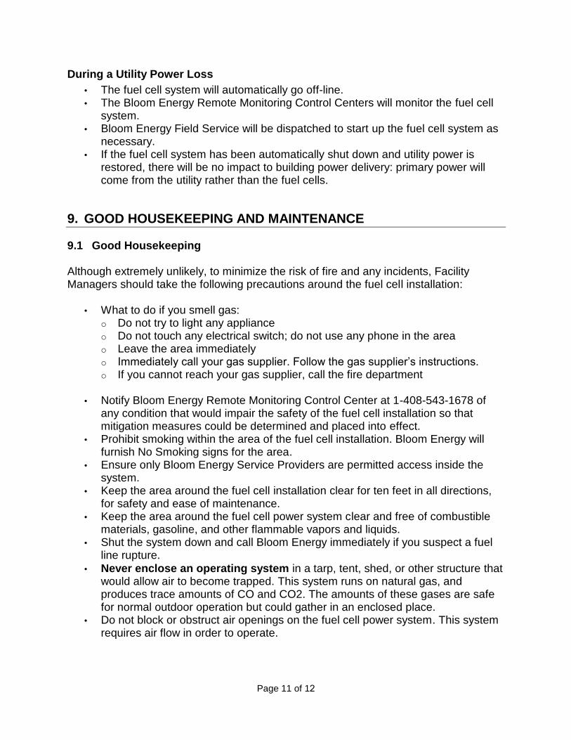
During a Utility Power Loss
• The fuel cell system will automatically go off-line.• The Bloom Energy Remote Monitoring Control Centers will monitor the fuel cell
system.• Bloom Energy Field Service will be dispatched to start up the fuel cell system as
necessary.• If the fuel cell system has been automatically shut down and utility power is
restored, there will be no impact to building power delivery: primary power willcome from the utility rather than the fuel cells.
9. GOOD HOUSEKEEPING AND MAINTENANCE
9.1 Good Housekeeping
Although extremely unlikely, to minimize the risk of fire and any incidents, Facility Managers should take the following precautions around the fuel cell installation:
• What to do if you smell gas:o Do not try to light any applianceo Do not touch any electrical switch; do not use any phone in the areao Leave the area immediatelyo Immediately call your gas supplier. Follow the gas supplier’s instructions.o If you cannot reach your gas supplier, call the fire department
• Notify Bloom Energy Remote Monitoring Control Center at 1-408-543-1678 ofany condition that would impair the safety of the fuel cell installation so thatmitigation measures could be determined and placed into effect.
• Prohibit smoking within the area of the fuel cell installation. Bloom Energy willfurnish No Smoking signs for the area.
• Ensure only Bloom Energy Service Providers are permitted access inside thesystem.
• Keep the area around the fuel cell installation clear for ten feet in all directions,for safety and ease of maintenance.
• Keep the area around the fuel cell power system clear and free of combustiblematerials, gasoline, and other flammable vapors and liquids.
• Shut the system down and call Bloom Energy immediately if you suspect a fuelline rupture.
• Never enclose an operating system in a tarp, tent, shed, or other structure thatwould allow air to become trapped. This system runs on natural gas, andproduces trace amounts of CO and CO2. The amounts of these gases are safefor normal outdoor operation but could gather in an enclosed place.
• Do not block or obstruct air openings on the fuel cell power system. This systemrequires air flow in order to operate.

Page 12 of 12
• Do not use this fuel cell power system if any part has been under water.Immediately call qualified service personnel to inspect the fuel cell power systemand to replace any functional part which has been under water.
• Please contact Bloom Energy at 408-543-1678 with as much advance notice aspossible if you plan, detect, or suspect a prolonged Internet outage.
• The Bloom Energy Field Service team will periodically clean the equipment; donot spray with pressurized hoses.
9.2 Maintenance
Your site has specific Field Service personnel assigned to it for both routine maintenance and troubleshooting. Your site project manager will introduce you to the designated Bloom Energy Field Service team assigned to your site prior to operation.
Bloom Energy Field Service personnel are trained in state Safety Law. They are trained in all the procedures required for the fuel cell installation, and their toolkit includes all the safety equipment required to work around the fuel components and high voltage in our system (480VAC).
Bloom Energy also requires its employees to follow all necessary safety precautions, including:
• Every time a Field Service technician arrives at a site for the first time and opensa service panel, the technician will use a leak detector to determine whetherthere is any gas buildup in the system and determine that it is safe to work on it.
• Whenever a Field Service technician is removing and replacing a component ona fuel or exhaust line, the technician must keep a CO detector nearby to makesure that no CO is present in the line even after the system has been shut down.
The Field Service team expects to conduct quarterly and yearly preventative maintenance for certain types of consumable or cleanable components such as replacement of air filters, water filters, and desulfurizer beds. Other maintenance will be performed as required. During such times, inspections for any hazards will be conducted including quarterly fire extinguisher inspection (if applicable).
10. TRAINING
Prior to system startup, a Bloom Energy representative will provide training on the fuel cell installation to include the location and operation of safety features as well as actions to take during emergencies. We desire this training to provide lasting value and are more than happy to work with you to customize the experience to suit your needs.

1299 Orleans Drive, Sunnyvale CA 94089 T 408 543 1500 F 408 543 1501 www.bloomenergy.com
Exhibit 7
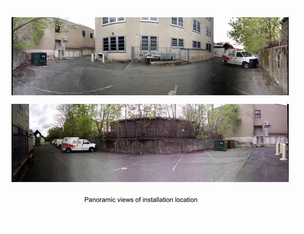
Panoramic views of installation location

1299 Orleans Drive, Sunnyvale CA 94089 T 408 543 1500 F 408 543 1501 www.bloomenergy.com
Exhibit 8

FEMA Flood Zones
Harbor Brook
Proposed Facility Location

1299 Orleans Drive, Sunnyvale CA 94089 T 408 543 1500 F 408 543 1501 www.bloomenergy.com
Exhibit 9
Mei Wu Acoustics 3 Twin Dolphin Drive, Suite 190, Redwood City, CA 94065-1516 Tel: (650) 592-1675 / Fax: (650) 508-8727 / www.mei-wu.com
1
Mei Wu Acoustics
Experts in acoustics, noise and vibration
To: Justin Adams, Bloom Energy [email protected]: Joshua Marcley, Mei Wu Acoustics [email protected]
Tyler Adams, Mei Wu Acoustics [email protected] Wu, Mei Wu Acoustics [email protected]
Date: October 17, 2016 Subject: Bloom Energy – Frontier Communications - Meriden, CT
MWA Project – 16079
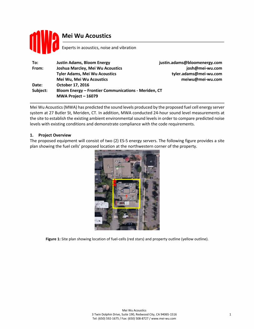
Mei Wu Acoustics (MWA) has predicted the sound levels produced by the proposed fuel cell energy server system at 27 Butler St, Meriden, CT. In addition, MWA conducted 24-hour sound level measurements at the site to establish the existing ambient environmental sound levels in order to compare predicted noise levels with existing conditions and demonstrate compliance with the code requirements.
1. Project OverviewThe proposed equipment will consist of two (2) ES-5 energy servers. The following figure provides a site plan showing the fuel cells’ proposed location at the northwestern corner of the property.
Figure 1: Site plan showing location of fuel-cells (red stars) and property outline (yellow outline).

MWA Project – 16079
Mei Wu Acoustics 3 Twin Dolphin Drive, Suite 190, Redwood City, CA 94065-1516 Tel: (650) 592-1675 / Fax: (650) 508-8727 / www.mei-wu.com
2
2. Noise Criteria This section documents the environmental noise criteria and code requirements applicable the project site. 2.1. Meriden Municipal Code
An excerpt of relevant portions of this code is provided here for reference:
Chapter 141 – Noise
Sec. 141-2- Definitions
When used in this chapter, the terms below shall have the following meanings:
AMBIENT NOISE or BACKGROUND NOISE - Noise of a measurable intensity which exists at a point as a result of a combination of many distant sources individually indistinguishable.
COMMERCIAL ZONE - Those areas designated as commercial districts in Chapter 213, Zoning, of the City Code.[1]
CONTINUOUS NOISE - Ongoing noise, the intensity of which remains at a measurable level (which may vary) without interruption over an indefinite period or a specified period of time.
DAYTIME HOURS - The hours between 7:00 a.m. and 9:00 p.m. Monday through Saturday and the hours between 9:00 a.m. and 9:00 p.m. on Sunday.
DECIBEL - A unit of measure of the sound level, the symbol for which is "dB."
EXCESSIVE NOISE - Any sound, the intensity of which exceeds the standards set forth in § 141-5.
IMPULSE NOISE - Sound of short duration, usually less than one second, with an abrupt onset and rapid decay, the level of which is measured with a sound-level meter, which shall conform to ANSI S127-1986 (R1993).
INDUSTRIAL ZONE - Those areas designated as industrial districts in Chapter 213, Zoning, of the City Code.[2]
NIGHTTIME HOURS - The hours between 9:00 p.m. and 7:00 a.m. Sunday evening through Saturday morning, between 9:00 p.m. and 9:00 a.m. Saturday evening through Sunday morning, and between 9:00 p.m. and 7:00 a.m. Monday through Friday.
NOISE - Any sound, the intensity of which exceeds the standards as set forth in this chapter.
NOISE LEVEL - The sound-pressure level as measured with a sound-level meter.
NOISE LEVEL, A-WEIGHTED - The sound-pressure level as measured with a sound-level meter using the A-weighting network. The sound level is designated "dBA."
PEAK SOUND-PRESSURE LEVEL (SPL) - The absolute maximum value of the instantaneous sound-pressure level occurring in a specified time period.
PROPERTY LINE - That real or imaginary line along the ground surface and its vertical extension which separates real property owned or controlled by any person from contiguous real property owned and controlled by another person and which separates real property from the public right-of-way.
PUBLIC RIGHT-OF-WAY - Any street, avenue, boulevard, highway, sidewalk, alley, park, waterway, railroad or similar place which is owned or controlled by a government entity, over which the public in general has a right of passage.
RESIDENTIAL ZONE - Those areas so designated in the Zoning Regulations of the City of Meriden.[3]
SOUND - A transmission of energy through solid, liquid or gaseous media in the form of vibrations which constitute alteration in pressure or position of particles in the medium and which, in air, evoke physiological sensations, including but not limited to an auditory response when impinging on the ear.
SOUND-LEVEL METER - An instrument used to measure sound levels. A sound-level meter shall conform, at a minimum, to the American National Standards Institute operation specifications for sound-level meters SI. 4-1983 (R 1994).
SOUND-PRESSURE LEVEL (SPL) - Equals 20 times the logarithm to the base 10 of the ratio of the sound pressure in question to the standard reference pressure of 20 micro pascals expressed in decibel (dB) units.
SOUND-PRESSURE LEVEL, A-WEIGHTED - The A-weighted sound-pressure level expressed in decibels (dBA), measured on a sound-level meter.

MWA Project – 16079
Mei Wu Acoustics 3 Twin Dolphin Drive, Suite 190, Redwood City, CA 94065-1516 Tel: (650) 592-1675 / Fax: (650) 508-8727 / www.mei-wu.com
3
Sec. 141-3 Noise Measurement Procedures
For the purpose of determining noise levels as set forth in this chapter, the following guidelines shall be applicable:
A. A person conducting sound measurement shall be trained in the current techniques and principles of sound measuring equipment and instrumentation.
B. Instruments used to determine sound-level measurement shall be sound-level meters and analyzers as defined by this chapter.
C. The following steps should be taken when preparing to take sound-level measurements:
(1) The instrument manufacturer's specific instructions for the preparation and use of the instrument shall be followed.
(2) If using a sound-level meter, it shall be calibrated before and after each set of measurements.
(3) If using a sound-level meter, it shall be placed at an angle from the sound source as specified by the manufacturer's instructions and at least four feet above the ground. It shall be placed at that location so as not to be interfered with by individuals conducting measurements.
(4) Measurements to determine compliance with § 141-5 shall be taken at a point that is located more or less than one foot beyond the property line of the noise emitter's premises and within the noise receptor's premises.
(5) While measurements are being recorded, a continual visual and aural surveillance of extraneous sound sources shall be made to ensure that the measurements are due to the sound being investigated. The sound levels of extraneous sound sources shall be recorded.
(6) The intentional moving or rendering inaccurate or inoperative of any sound-monitoring device or instrument positioned or used by or for the City of Meriden, provided that such device or the immediate area is clearly labeled to warn of the potential illegality, shall be a violation of this chapter.
Sec. 141-4 Classification of Noise Zones
Noise zones within the City of Meriden shall be classified as to zoning applicable for the parcel or tract of land and the surrounding parcels or tracts. Noise zones specified herein shall correspond to the following zoning descriptions in the Zoning Regulations and Zoning Map of the City of Meriden:
Zone Actual or Intended Use
Class A Residential
Class B Commercial
Class C Industrial
Sec. 141-5 Noise Zone Standards
A. No person shall, except as provided in this chapter, allow or permit the creation, continuance or maintenance of any noise beyond the property line of his/her premises in excess of the noise levels established in these regulations.
B. It shall be unlawful for any person to emit or cause to be emitted any noise beyond the property lines or boundaries of his/her premises in excess of the following noise levels:
Emitter Noise Zone
C
(dBA)
B
(dBA)
A-Day
(dBA)
A-Night
(dBA)
Class C 70 66 61 51
Class B 62 62 55 45
Class A 62 55 55 45
C. Impulse noise standards.
(1) Class A receptor, nighttime. It shall be unlawful for any person to emit or cause to be emitted any impulse noise beyond the property lines of his/her premises to a Class A receptor noise zone during nighttime hours in excess of 80 dB peak sound-pressure level.

MWA Project – 16079
Mei Wu Acoustics 3 Twin Dolphin Drive, Suite 190, Redwood City, CA 94065-1516 Tel: (650) 592-1675 / Fax: (650) 508-8727 / www.mei-wu.com
4
(2) Any receptor, at any time. It shall be unlawful for any person to emit or cause to be emitted any impulse noise beyond the property lines of his/her premises to any receptor noise zone at any time in excess of 100 dB peak sound-pressure level.
D. High background noise levels and impulse noise.
(1) In those individual cases where the background noise levels caused by sources not subject to these regulations exceed the standards contained herein, a source shall be considered to cause excessive noise if the noise emitted by such source exceeds the background noise levels by five dBA, provided that no source subject to the provisions of this chapter shall emit noise in excess of 80 dBA at any time and provided that this section does not decrease the permissible levels of other sections of this chapter.
(2) No person shall cause or allow the emission of impulse noise in excess of 80 dB peak sound-pressure level during the nighttime to any residential noise zone.
(3) No person shall cause or allow the emission of impulse noise in excess of 100 dB peak sound-pressure level at any time to any zone

MWA Project – 16079
Mei Wu Acoustics 3 Twin Dolphin Drive, Suite 190, Redwood City, CA 94065-1516 Tel: (650) 592-1675 / Fax: (650) 508-8727 / www.mei-wu.com
5
2.2. Meriden City Plan MWA has reviewed the Meriden City Plan and was not able to locate a “Noise Element” portion of this general plan. The Noise Element typically provides goals and policies to guide compatible land uses and the incorporation of noise attenuation measures for new uses to protect people living and working in the City from an excessive noise environment.
2.3. Meriden Zoning Map
The following figure provides a zoning map of the areas surrounding the project site. As shown, the project site is zoned TOD-Hanover, a Transit Oriented Development District, which is considered business/commercial. To the north and east is another transit oriented district, considered business/commercial in this analysis. However we note that the actual land uses to the east of the project site appear to be residential.
TOD-Historic/Commercial – Transit Oriented Development District TOD-Hanover – Tranist Oriented Development District
Figure 2: Meriden Zoning Map – Approximate location of fuel cells indicated by red star.

MWA Project – 16079
Mei Wu Acoustics 3 Twin Dolphin Drive, Suite 190, Redwood City, CA 94065-1516 Tel: (650) 592-1675 / Fax: (650) 508-8727 / www.mei-wu.com
6
2.4. Connecticut Department of Energy and Environmental Protection (DEEP) The Connecticut Siting Council (Council) is an autonomous agency residing within the merged Department of Energy and Environmental Protection (DEEP). The following is an exceprt of their noise requirements: Sec.22a-69-1 Definitions
(h) daytime means 7:00 a.m. to 10:00 p.m. local time. (n) nighttime means 10:00 p.m. to 7:00 a.m. local time.
Sec.22a-69-1.2 Acoustic Terminology and definitions
(c) background noise means noise which exists at a point as a result of the combination of many distant sources, individually indistinguishable. In statistical terms, it is the level which is exceeded 90% of the time (L90) in which the measurement is taken.
(f) excessive noise means emitter Noise Zone levels from stationary noise sources exceeding the Standards set forth in Section 3 of these Regulations beyond the boundary of adjacent Noise Zones.
Sec.22a-69-2 Classification of land according to use
Sec. 22a-69-2.1. Basis Noisy Zone classifications shall be based on the actual use of any parcel or tract under single ownership as detailed by the Standard Land Use Classification Manual of Connecticut
Sec. 22a-69-2.2. Multiple uses Where multiple uses exist within a given Noise Zone, the least restrictive land use category for the Emitter and Receptor shall apply regarding the noise standards specified in Section 3 of these Regulations.
Sec. 22a-69-2.3. Class A noise zone Lands designated Class A shall generally be residential areas where human beings sleep or areas where serenity and tranquility are essential to the intended use of the land. Class A Land Use Category. The land uses in this category shall include, but not be limited to, single and multiple family homes, hotels, prisons, hospitals, religious facilities, cultural activities, forest preserves, and land intended for residential or special uses requiring such protection
Sec. 22a-69-2.4. Class B noise zone Lands designated Class B shall generally be commercial in nature, areas where human beings converse and such conversation is essential to the intended use of the land.
Sec. 22a-69-3. Allowable Noise Levels Sec. 22a-69-3.1. General prohibition No person shall cause or allow the emission of excessive noise beyond the boundaries of his/her Noise Zone so as to violate any provisions of these Regulation
Sec. 22a-69-3.5. Noise zone standards (b) No person in a Class B Noise Zone shall emit noise exceeding the levels stated herein and applicable to adjacent
Noise Zones:
Class C Receiver Class B Receiver Class A Receiver Day Class A Receiver Night
Class B Emitter 62 dBA 62 dBA 55 dBA 45 dBA
Levels emitted in excess of the values listed above shall be considered excessive noise.
Sec. 22a-69-3.6. High background noise areas In those individual cases where the background noise levels caused by sources not subject to these Regulations exceed the standards contained herein, a source shall be considered to cause excessive noise if the noise emitted by such source exceeds the background noise level by 5 dBA, provided that no source subject to the provisions of Section 3 shall emit noise in excess of 80 dBA at any time, and provided that this Section does not decrease the permissible levels of the other Sections of this Regulation
MWA Project – 16079
Mei Wu Acoustics 3 Twin Dolphin Drive, Suite 190, Redwood City, CA 94065-1516 Tel: (650) 592-1675 / Fax: (650) 508-8727 / www.mei-wu.com
7
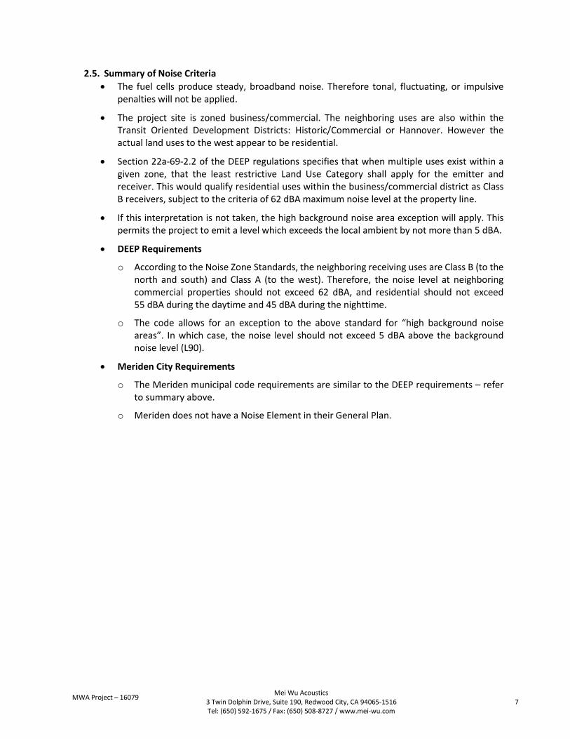
2.5. Summary of Noise Criteria
The fuel cells produce steady, broadband noise. Therefore tonal, fluctuating, or impulsive penalties will not be applied.
The project site is zoned business/commercial. The neighboring uses are also within the Transit Oriented Development Districts: Historic/Commercial or Hannover. However the actual land uses to the west appear to be residential.
Section 22a-69-2.2 of the DEEP regulations specifies that when multiple uses exist within a given zone, that the least restrictive Land Use Category shall apply for the emitter and receiver. This would qualify residential uses within the business/commercial district as Class B receivers, subject to the criteria of 62 dBA maximum noise level at the property line.
If this interpretation is not taken, the high background noise area exception will apply. This permits the project to emit a level which exceeds the local ambient by not more than 5 dBA.
DEEP Requirements
o According to the Noise Zone Standards, the neighboring receiving uses are Class B (to the north and south) and Class A (to the west). Therefore, the noise level at neighboring commercial properties should not exceed 62 dBA, and residential should not exceed 55 dBA during the daytime and 45 dBA during the nighttime.
o The code allows for an exception to the above standard for “high background noise areas”. In which case, the noise level should not exceed 5 dBA above the background noise level (L90).
Meriden City Requirements
o The Meriden municipal code requirements are similar to the DEEP requirements – refer to summary above.
o Meriden does not have a Noise Element in their General Plan.

MWA Project – 16079
Mei Wu Acoustics 3 Twin Dolphin Drive, Suite 190, Redwood City, CA 94065-1516 Tel: (650) 592-1675 / Fax: (650) 508-8727 / www.mei-wu.com
8
3. Environmental Ambient Sound Level Measurements 3.1. Site visit details
MWA personnel: Joshua Marcley Date and time: 9/27/2016 12:00 PM – 9/28/2016 10:30 AM Equipment used: Cesva SC160, Type II sound level meter
3.2. Measurement procedure A sound level meter was installed on a tree on the edge of the southern property line (the nearest adjacency to residential use). Ambient sounds were comprised primarily of traffic from in the downtown Meriden area.
The sound level meter recorded A-weighted Leq, L1, L5, L10, L50, L90, L95, and L99 levels every one (1) minute for the time period described above. The meter was equipped with a windscreen. The measurement was aborted after 22 hours, 20 minutes due to weather concerns. The last 20 minutes of collected data is averaged and extrapolated to represent the entire final hour of the measurement.
3.3. Measurement Period Weather Conditions The following table provides the weather conditions during the measurement period.
Date 9/27/2016 9/28/2016 Mean Temp. 66° F 59° F
Max Temp. 73° F 66° F
Min Temp. 57° F 54° F
Avg. Humidity 80% 84%
Avg. Wind Speed 5 mph [W] 7 mph [NE]
Precipitation 0.42 in 0.00 in
Table 1: Measurement weather conditions

MWA Project – 16079
Mei Wu Acoustics 3 Twin Dolphin Drive, Suite 190, Redwood City, CA 94065-1516 Tel: (650) 592-1675 / Fax: (650) 508-8727 / www.mei-wu.com
9
3.4. Measurement Results The following table provides the hourly average sound level measurements. All measurements indicated are given in dBA (A-weighted). LAeq is the average measured level for the entire 1-hour measurement period. L1/10/L90/L99 are statistical averages – for example, L10 indicates the level that was present for 10% of the time, whereas L90 indicates the level present for 90% of the measurement period. L99 & L90 are considered representative of the steady background sound levels, whereas L1 & L10 may suggest more infrequent and transient activities in the environment (door slams, car alarms, dog barking, etc.). The quietest 1-Hour L90 was 51.3 dBA, measured from 12–1PM.
Hour L1 L10 L90 L99 LAeq
12:00 PM 63.4 56.3 51.3 50.7 54.5
1:00 PM 59.8 55.3 51.4 50.8 53.4
2:00 PM 62.5 55.6 51.9 51.3 54.2
3:00 PM 68.5 61.2 52.2 51.5 58.0
4:00 PM 69.7 62.4 52.6 51.9 59.4
5:00 PM 65.6 58.8 52.0 51.5 56.0
6:00 PM 70.8 64.1 52.3 51.6 60.4
7:00 PM 56.4 54.4 52.2 51.7 53.2
8:00 PM 61.4 56.5 52.3 51.7 54.5
9:00 PM 54.4 53.1 51.9 51.5 52.5
10:00 PM 55.9 53.4 51.8 51.5 52.6
11:00 PM 56.7 53.5 52.0 51.6 52.8
12:00 AM 56.7 54.2 51.8 51.5 52.9
1:00 AM 54.5 53.1 51.9 51.5 52.5
2:00 AM 58.2 54.9 52.3 51.9 53.6
3:00 AM 64.7 57.5 53.2 52.7 55.7
4:00 AM 60.1 56.5 53.9 53.4 55.3
5:00 AM 62.5 57.2 54.3 53.9 55.9
6:00 AM 73.9 66.0 54.8 54.1 62.4
7:00 AM 63.9 58.8 54.4 53.8 56.9
8:00 AM 62.1 58.0 53.8 53.2 56.0
9:00 AM 62.8 59.9 54.4 53.7 57.4
10:00 AM 63.1 56.8 52.1 50.9 54.5
CNEL 63.1
Table 2: Hourly environmental sound level measurements – 9/27 – 9/28/2016 (dBA)
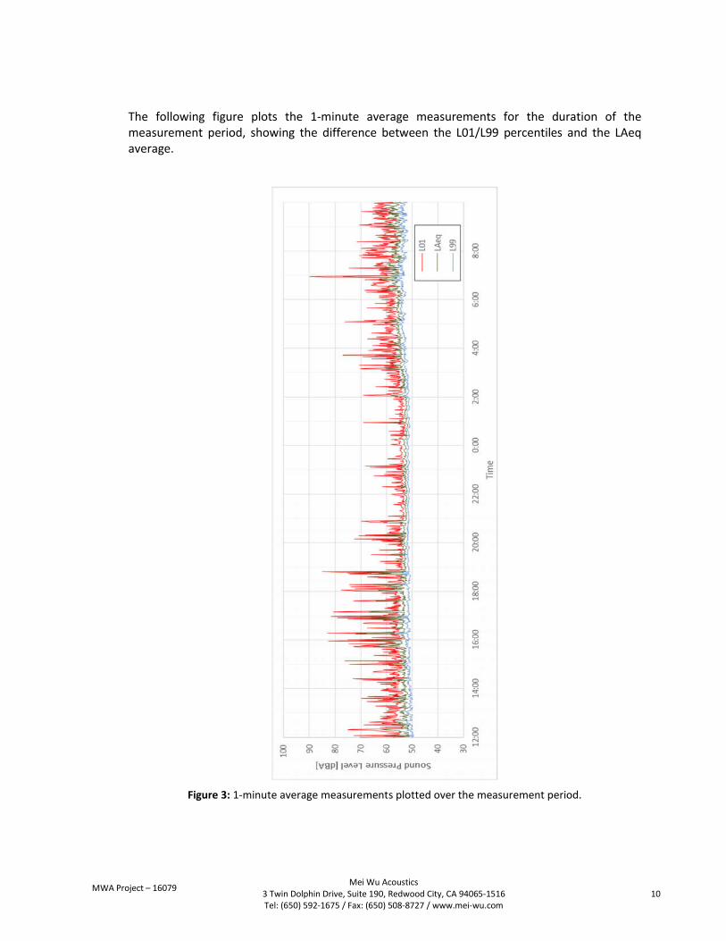
MWA Project – 16079
Mei Wu Acoustics 3 Twin Dolphin Drive, Suite 190, Redwood City, CA 94065-1516 Tel: (650) 592-1675 / Fax: (650) 508-8727 / www.mei-wu.com
10
The following figure plots the 1-minute average measurements for the duration of the measurement period, showing the difference between the L01/L99 percentiles and the LAeq average.
Figure 3: 1-minute average measurements plotted over the measurement period.
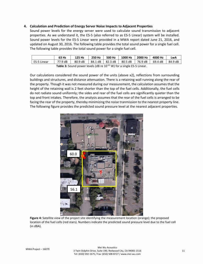
MWA Project – 16079
Mei Wu Acoustics 3 Twin Dolphin Drive, Suite 190, Redwood City, CA 94065-1516 Tel: (650) 592-1675 / Fax: (650) 508-8727 / www.mei-wu.com
11
4. Calculation and Prediction of Energy Server Noise Impacts to Adjacent Properties Sound power levels for the energy server were used to calculate sound transmission to adjacent properties. As we understand it, the ES-5 (also referred to as ES-5 Linear) system will be installed. Sound power levels for the ES-5 Linear were provided in a MWA report dated June 21, 2016, and updated on August 30, 2016. The following table provides the total sound power for a single fuel cell. The following table provides the total sound power for a single fuel cell.
63 Hz 125 Hz 250 Hz 500 Hz 1000 Hz 2000 Hz 4000 Hz LwA
ES-5 Linear 77.9 dB 80.9 dB 84.1 dB 82.3 dB 80.5 dB 76.9 dB 69.4 dB 84.9 dB
Table 3: Sound power levels (dB re 10-12 W) for a single ES-5 Linear.
Our calculations considered the sound power of the units (above x2), reflections from surrounding buildings and structures, and distance attenuation. There is a retaining wall running along the rear of the property. Though it was not measured during our measurement, the calculation assumes that the height of the retaining wall is 2 feet shorter than the top of the fuel cells. Additionally, the fuel cells do not radiate sound uniformly; the sides and rear of the fuel cells are significantly quieter than the top and front intakes. Therefore, the analysis assumes that the rear of the fuel cells is arranged to be facing the rear of the property, thereby minimizing the noise tranmission to the nearest property line. The following figure provides the predicted sound pressure level at the nearest adjacent properties.
Figure 4: Satellite view of the project site identifying the measurement location (orange); the proposed location of the fuel cells (red stars). Numbers indicate the predicted sound pressure level due to the fuel cell (in dBA).
60.0
56.1
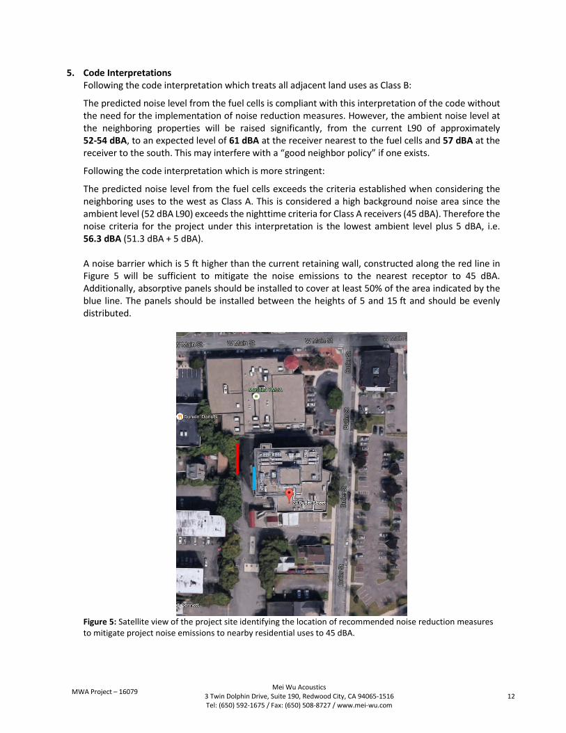
MWA Project – 16079
Mei Wu Acoustics 3 Twin Dolphin Drive, Suite 190, Redwood City, CA 94065-1516 Tel: (650) 592-1675 / Fax: (650) 508-8727 / www.mei-wu.com
12
5. Code Interpretations Following the code interpretation which treats all adjacent land uses as Class B:
The predicted noise level from the fuel cells is compliant with this interpretation of the code without the need for the implementation of noise reduction measures. However, the ambient noise level at the neighboring properties will be raised significantly, from the current L90 of approximately 52-54 dBA, to an expected level of 61 dBA at the receiver nearest to the fuel cells and 57 dBA at the receiver to the south. This may interfere with a “good neighbor policy” if one exists.
Following the code interpretation which is more stringent:
The predicted noise level from the fuel cells exceeds the criteria established when considering the neighboring uses to the west as Class A. This is considered a high background noise area since the ambient level (52 dBA L90) exceeds the nighttime criteria for Class A receivers (45 dBA). Therefore the noise criteria for the project under this interpretation is the lowest ambient level plus 5 dBA, i.e. 56.3 dBA (51.3 dBA + 5 dBA). A noise barrier which is 5 ft higher than the current retaining wall, constructed along the red line in Figure 5 will be sufficient to mitigate the noise emissions to the nearest receptor to 45 dBA. Additionally, absorptive panels should be installed to cover at least 50% of the area indicated by the blue line. The panels should be installed between the heights of 5 and 15 ft and should be evenly distributed.
Figure 5: Satellite view of the project site identifying the location of recommended noise reduction measures to mitigate project noise emissions to nearby residential uses to 45 dBA.

MWA Project – 16079
Mei Wu Acoustics 3 Twin Dolphin Drive, Suite 190, Redwood City, CA 94065-1516 Tel: (650) 592-1675 / Fax: (650) 508-8727 / www.mei-wu.com
13
6. Summary & Conclusion The calculations show that the noise level at the location closest to the fuel cell along the property line is expected to be 60.0 dBA and 56.1 dBA, at the property lines of the two nearest receivers (see Figure 4). The calculation is valid assuming that the retaining wall at the rear of the property is 2 feet shorter than the top of the fuel cells, or taller, and that the fuel cells be aligned such that the rear of the fuel cells face the rear of the property.
Please refer to Section 5 for our comments regarding the code interpretations for this site.
This concludes our report. Please contact Mei Wu Acoustics if there are any questions or comments regarding this document.
* * *

1299 Orleans Drive, Sunnyvale CA 94089 T 408 543 1500 F 408 543 1501 www.bloomenergy.com
Exhibit 10
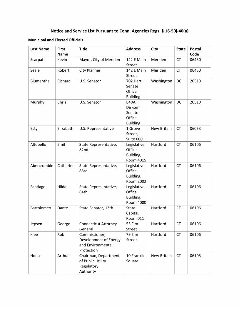
Notice and Service List Pursuant to Conn. Agencies Regs. § 16-50j-40(a)
Municipal and Elected Officials
Last Name First Name
Title Address City State Postal Code
Scarpati Kevin Mayor, City of Meriden 142 E Main Street
Meriden CT 06450
Seale Robert City Planner 142 E Main Street
Meriden CT 06450
Blumenthal Richard U.S. Senator 702 Hart Senate Office Building
Washington DC 20510
Murphy Chris U.S. Senator B40A Dirksen Senate Office Building
Washington DC 20510
Esty Elizabeth U.S. Representative 1 Grove Street, Suite 600
New Britain CT 06053
Altobello Emil State Representative, 82nd
Legislative Office Building, Room 4015
Hartford CT 06106
Abercrombie Catherine State Representative, 83rd
Legislative Office Building, Room 2002
Hartford CT 06106
Santiago Hilda State Representative, 84th
Legislative Office Building, Room 4000
Hartford CT 06106
Bartolomeo Dante State Senator, 13th State Capital, Room 011
Hartford CT 06106
Jepsen George Connecticut Attorney General
55 Elm Street
Hartford CT 06106
Klee Rob Commissioner, Development of Energy and Environmental Protection
79 Elm Street
Hartford CT 06106
House Arthur Chairman, Department of Public Utility Regulatory Authority
10 Franklin Square
New Britain CT 06105

Rino Raul Commissioner, Department of Public Health Protection
410 Capital Avenue, PO Box 340308
Hartford CT 06134
Merrow Susan Chair, Council on Environmental Quality
79 Elm Street
Hartford CT 06106
Revicky Steven Commissioner, Department of Agriculture
165 Capital Avenue
Hartford CT 06106
Barnes Benjamin Secretary of OPM, Office of Policy and Management
450 Capital Avenue
Hartford CT 06106
Redeker James Commissioner, Department of Transportation
2800 Berlin Turnpike
Newington CT 06111
Abutter Properties
Map ID Number
Name Address City State
Zip
30 MERIDEN CITY OF PARKING LOT
142 E MAIN ST MERIDEN CT 06450
88 HOUSING AUTHORITY OF THE CITY
22 CHURCH ST MERIDEN CT 06450
9 MERIDEN CITY OF 142 E MAIN ST MERIDEN CT 06450 110 MERIDEN CITY OF 142 E MAIN ST MERIDEN CT 06450 122 MERIDEN CITY OF 142 E MAIN ST MERIDEN CT 06450 20 MCINVALLE HOUSTON 18 OXFORD DR MIDDLEFIEL
D CT 06455
32 LEV REALTY LLC 619 EASTERN PKWY BROOKLYN NY 10016 48 BEECHER & BENNETT INC 48 COOK AVE MERIDEN CT 06451 131 BEECHER & BENNETT INC 48 COOK AVE MERIDEN CT 06451 136 ONE THIRTY EIGHT
HANOVER LLC 273 WEST MAIN ST MERIDEN CT 06451
124 124 HANOVER LLC 1739 SAINT PETERS AVE BRONX NY 10461 109 DEVRIES KURT 14 E HADDAM
COLCHESTER TPKE MOODUS CT 06469
43 DEVRIES KURT 14 E HADDAM COLCHESTER TPKE
MOODUS CT 06469
41 HALLOCK THOMAS W 41 BUTLER ST RR MERIDEN CT 06451 39 PATRUCCO JON 39 BULER ST MERIDEN CT 06451 35 SOUTHERN NEW ENGLAND
TEL CO 401 MERRIT 7 NORWALK CT 06851
1299 Orleans Drive, Sunnyvale CA 94089 T 408 543 1500 F 408 543 1501 www.bloomenergy.com
Exhibit 11

Abutters Map - Meriden GIS

1299 Orleans Drive, Sunnyvale CA 94089 T 408 543 1500 F 408 543 1501 www.bloomenergy.com
Exhibit 12