RE 00853 09.07 · 2020-03-06 · The safety notes and product information in the above...
25
1 Foreword Bosch Rexroth AG I RE 00853/09.07 Foreword This teachware was created as a collection of tasks, solutions and software proj- ects for the modular mechatronic system mMS from Rexroth, which is intended for industrial basic and further training of mechatronicians. The modular tasks meet professional requirements. The practical exercises basically deal with the contents of the training manual "Mechatronics. Theory and Application" and, with regard to the degree of difficulty, range from "beginner" to "expert". The experience gained in training courses of successful mechatronics seminars in the last few years was integrated in this manual. For example, the programming language "Sequential Function Chart" to IEC61131-3 is to be used preferably in seminars attended by beginners, but knowledge of all the required languages according to IEC61131-3 is imparted.
Transcript of RE 00853 09.07 · 2020-03-06 · The safety notes and product information in the above...

1Foreword Bosch Rexroth AG I RE 00853/09.07
ForewordThis teachware was created as a collection of tasks, solutions and software proj-ects for the modular mechatronic system mMS from Rexroth, which is intended for industrial basic and further training of mechatronicians. The modular tasks meet professional requirements. The practical exercises basically deal with the contents of the training manual "Mechatronics. Theory and Application" and, with regard to the degree of difficulty, range from "beginner" to "expert". The experience gained in training courses of successful mechatronics seminars in the last few years was integrated in this manual. For example, the programming language "Sequential Function Chart" to IEC61131-3 is to be used preferably in seminars attended by beginners, but knowledge of all the required languages according to IEC61131-3 is imparted.

2Foreword Bosch Rexroth AG I RE 00853/09.07
Notes

3Introduction Bosch Rexroth AG I RE 00853/09.07
The present trainee's manual helps to acquire the required specialist knowledge of sensorics, actorics, control technology, and mechatronics in practice-oriented applications.
With the help of logically structured project work, the trainee:
• is to become able to explain the function, structure, practical operating principle, and possible applications of pneumatic equipment;
• is to become able to read and understand electrical and pneumatic symbols and circuit diagrams;
• is to be made familiar with basic controls of mechatronics and become able to control assemblies with the help of operating diagrams, electrical circuit diagrams and programs;
• is to become able to understand regularities and functional interrelationships (state machine, senors, transition, actuators);
• is to become able to program PLC sequence controls using IndraWorks, IndraLogic L20.
The project solutions described in the trainee's manual for the mechatronic system mMS from Rexroth provide trainers and trainees with guidelines and instruments for meeting the requirements in imparting specialist knowledge in the field of me-chatronics.
The objectives described are geared to the development of competence to act. The trainee will develop his or her competence to act from the capability and willingness to solve tasks and problems and evaluate results in a target-oriented manner, skillfully, methodically and independently.
Imparting knowledge through project work
Training con-tents
Specialist com-petence

4Introduction Bosch Rexroth AG I RE 00853/09.07
Professional competence to act
The projects described in the project definition are oriented towards practical needs and are characterized by a high level of conformity with customer orders from industry and trade. Customer orders represent comprehensive activities and develop and promote the trainee's professional competence.
As mentioned before, the trainee is to work off the project task or the project order in 6 steps.
1. InformingBased on the project definition, the trainee is to get a clear idea of the finished solution, including any required details. This is achieved through systematic analysis of the project documentation and, if required, by asking questions.
Possible questions: • What is to be done? • Have I understood the task completely? • Which component/system is to be worked out?
2. PlanningPlanning means the theoretical preparation and anticipation of the concrete execution. In detail, planning requires competence to handle the project order and to organize the project handling steps.
Possible questions: • How to proceed? • What knowledge is required? • Which aids are available? • Are there comparable applications in my company?
3. Decision-makingAfter the planning stage, the trainee determines the aids to be used, e.g. which data sheets are required for coping with the project task. He/she decides on the sequence and the interrelationships of the individual project steps. Moreover, a decision should be made as to whether it would be easier to solve the project task in a team.
Possible questions: • Which electrical and pneumatic components will be used?
• How can you know that technical data sheets are up to date?
• Have I utilized all available sources of information? • Are the prescribed safety instructions at hand?

5Introduction Bosch Rexroth AG I RE 00853/09.07
4. Executing:The order is to be executed according to the work instructions given in the chapter "order execution", taking all safety notes into account. After a thorough preparatory phase, the trainee is to carry out the project order largely on his/her own. After the solution was worked out in writing, it should be verified or ques-tioned, whether the right attempt at the solution was selected.Depending on the project order, the possibilities of execution may be limited. This is valid, for example, in the case of costly work in the field of information technology.
Possible questions: • Have I chosen the correct sequence?
5. Checking:The trainee must check intermediate results as early as during the execution stage, and finally the result of the customer requirement. In some cases, the result can be compared with the manufacturer's documents. In the case of measuring exercises, it must be checked, whether the measured results are realistic.
6. Evaluating:In the final evaluation phase, an external or self-evaluation is to be carried out on the basis of a comparison of project order documents, the installed control and results of measurements and checks.Faults, if any, and their causes must be analyzed and possibilities discussed as to how faults can be avoided in the future.The trainee must learn to assess his/her strengths and weaknesses and develop objective quality standards for his/her acting, which ultimately leads to personal competence. The evaluation can be finalized in a technical discussion, possibly also in a discussion with the customer.

6Introduction Bosch Rexroth AG I RE 00853/09.07
Project designation with short description of the industrial application
This trainee's manual includes the following 9 project extercises:
No. Project designation Industrial application
01
Observing, analyzing and docu-menting in the beginner's appli-cation for the mMS reality with Station 2 - Processing
Planning of work sequences, controlling and checking work results, and documentation
02
Understanding the basic technol-ogy in the beginner's application for electrics/sensorics on the basis of Station 2
Installation of electrical assem-blies and components, measure-ment and testing of electrical variables
03
Basic principles of PLC pro-gramming with L20 in the begin-ner's application for the electrical conveyor belt
Introduction into PLC program-ming using IndraLogic L20, pro-gramming of simple mechatronic assemblies
04Hardware programming in the beginner's application for a pneumatic press
Basic programming language, creation of a new project
05
Machine safety, emergency stop, CE-marking in the beginner's ap-plication for emergency stop with PNOZ Station 2
Hazard analysis, setup of electri-cal controls, function test and machine safety
06Hardware programming in the expert's application for the han-dling device of Station 2
Extended programming languag-es, programming of complex mechatronic assemblies
07
Implementing 04 and 06 in the programmed overall system in the expert's application for the PLC project structure in Station 2
Extended programming languag-es, programming of complex mechatronic assemblies
08
Commissioning stations and the overall system in the expert's ap-plication for the commissioning sequence of Station 2
Commissioning, testing of com-plex mechatronic system, under-standing existing PLC projects
09
Pinpointing and elimination of faults in the expert application for troubleshooting with inter-changed cables on Station 2
Maintenance of complex mecha-tronic systems, fault diagnosis and elimination of faults
The trainer imparts mechatronic basic knowledge in 9 individual projects. De-tailed project definitions with customer requirements help the trainee to under-stand the function and possible applications of individual system components in the course of the order execution.

7Introduction Bosch Rexroth AG I RE 00853/09.07
Training preparationFor the preparation of a successful training course, it is required that all compo-nents and documents listed below are at hand. This ensures swift progression in the training course.
Not more than two people should work on a PC workstation at a time. If a proj-ect is to be tested on the mechatronic system, it is recommended to use blank compact flash cards. The original program should never be erased or changed. Additional compact flash cards are available as optional accessories.
Before a program can be commissioned on a mechatronic system, it must be released by a specialist, and the persons involved must be informed accordingly. Faulty programs can lead to injury or damage to the system.
The programs given in this document were created with IndraWorks (SWA-IWORKS-IL*-03VRS-D0-CD650). With other versions, deviations are pos-sible.
For the comprehensive use of this teachware, the following components, tools, and documents are required:
Hardware:
• R961003177 mMS - mechatronic system with pneumatic press• R961003450 mMS - mechatronic station for processing using a pneumatic press
Standards:
• DIN EN 414• DIN EN 954-1• DIN EN 294• EN 999• EN 418• EN 574 or technical manual "Mechatronics. Theory and Application"
Tools:
• Set of wrenches• Small slot screw driver, max. 3 mm• Digital multi-meter (for commissioning and troubleshooting)• Compact flash card per station for training purposes

8Introduction Bosch Rexroth AG I RE 00853/09.07
PC / laptop with:
• Ethernet network card• Windows 2000 / Windows XP• Software IndraWorks / IndraLogic• Adobe Acrobat Reader• Microsoft Office• Programming cable (Ethernet cross-link)
CD: TS-MMS DOK DE / EN R961003719This CD contains all the required data sheets and operating instructions for the mechatronic system mMS. Every trainee must have access to these documents in electronic or printed form.
CD: TS-MMS PROJEKTHANDBUCH DE/EN R961003747This CD contains all solution projects for the present project manual. Moreover, additional data is provided, which is required for the training sequence.

1Safey notes Bosch Rexroth AG I RE 00853/09.07
Warning
Attention
This symbol refers to imminent danger that, if not avoided, can lead to severest injuries or death.
This symbol refers to a potential risk, which can lead to light or serious injuries or damage to property.
This symbol refers to supplementary information.
Conventions
Fundamental safey notesSafety and the economic use of resources are essential demands that are placed on modern plant and machinery and serve to protect people. These two requirements have in common that they have to be taken into ac-count as early as possible, that is, at the product concept stage. Only in this way can optimized and low-priced solutions be found. Safe machines with low consumption demonstrate that the manufacturer masters his processes; they are a quality feature.
In order that hazards to plant and machinery can be recognized, safety regula-tions, product information brochures and operating instructions must be ob-served. Corresponding notes on the handling of electrohydraulic components and systems of Bosch Rexroth can be found in:
• Operating instructions "Modular mechatronic system mMS" RE 09950-B … RE 09955-B
• Rexroth IndraControl L20 – Projekt Planning R911312327
• Rexroth IndraWorks Engineering R911317336
• Various data sheets on hydraulic, pneumatic and electrical components, CD: TS-MMS DOK DE / EN R961003719
The safety notes and product information in the above documentation are ex-clusively valid for Bosch Rexroth products. Only when operating instructions, safety notes and product information are observed can the trouble-free operation of Rexroth products be ensured.
The present Project Manual Mechatronics includes warning notes, which pre-cede instructions for activities that involve a risk of personal injury or damage to property. The described precautions for averting risks must be taken.

2Safey notes Bosch Rexroth AG I RE 00853/09.07
Warning
Liability
Installation, commissioning and operation, disassembly, upkeep and maintenance require fundamental knowledge in the field of mechanics, pneumatics, controls and electrical engineering as well as the knowledge of related technical terms. In order to ensure operational safety, these activities may only be carried out by a corresponding specialist or by an instructed person under the supervision of a specialist.
A specialist is, who, due to his/her professional training, his/her knowledge and experience and the knowledge of relevant regulations, can asses the duties assigned to him/her, recognize potential risks and take suitable precautions. A specialist must observe relevant technical rules.
Consequently, this means that the trainer must point out potential risks to the trainees and provide information on how to avert such risks.
Work carried out improperly on electrohydraulic components and systems involves the risk of injury and represents a safety risk during operation of the system, including danger to life!
In the case of damage resulting from improper use and unauthorized interven-tions, which are not provided in the Project Manual Mechatronics, any liability claims for defects or other liability claims vis-à-vis Bosch Rexroth AG become void.
If Projects 01 to 09 described in the Project Manual Mechatronics are carried out on training stands that were not delivered by Rexroth, that is, products of competitors' make, any defect or liability claims vis-à-vis Bosch Rexroth AG shall be void as well.
Qualification of personnel
Note:
The components and systems described in this Project Manual are technical equipment, which is not intended for private use.
The use for the intended purpose also implies that the safety regulations, product information and operating instructions described in the following are read and understood.
Installation, commissioning and operation, disassembly, upkeep and maintenance require fundamental knowledge in the field of mechanics, pneumatics, controls and electrical engineering as well as the knowledge of related technical terms. In order to ensure operational safety, these activities may only be carried out by a corresponding specialist or by an instructed person under the supervision of a specialist.
A specialist is, who, due to his/her professional training, his/her knowledge and experience and the knowledge of relevant regulations, can asses the duties assigned to him/her, recognize potential risks and take suitable precautions. A specialist must observe relevant technical rules.
Consequently, this means that the trainer must point out potential risks to the trainees and provide information on how to avert such risks.
Work carried out improperly on electrohydraulic components and systems involves the risk of injury and represents a safety risk during operation of the system, including danger to life!
In the case of damage resulting from improper use and unauthorized interven-tions, which are not provided in the Project Manual Mechatronics, any liability claims for defects or other liability claims vis-à-vis Bosch Rexroth AG become void.
If Projects 01 to 09 described in the Project Manual Mechatronics are carried out on training stands that were not delivered by Rexroth, that is, products of competitors' make, any defect or liability claims vis-à-vis Bosch Rexroth AG shall be void as well.
Qualification of personnel
Note:
The components and systems described in this Project Manual are technical equipment, which is not intended for private use.

3Safey notes Bosch Rexroth AG I RE 00853/09.07
Warning
Warning
When using competitors' products, observe the safety notes of the manufacturer and make sure that the components and systems comply with currently valid EU Directives.
For this reason, commissioning is prohibited until it was estab-lished that the components and systems to be used comply with the stipulations of all relevant EU Directives.
Note:
The required safety regulations, product information documents* and operat-ing instructions must be handed over or be accessible to the trainee in their latest issue.
The mechatronic system may only be operated when in technically perfect condition.
The use for the intended purpose, performance data and operating conditions must not be changed.
Protective equipment / components must not be rendered inoperable, e.g. by bridging limit switches, valves or other control components.
If protective equipment must be bridged to allow servicing work to be carried out, precautions must be taken to ensure that no dangerous situation can arise. The higher-order machine operating instructions must be observed.
Adjustment features on components may exclusively be operated or changes to programmable control systems made by authorized personnel within the framework of the intended use of the mechatronic system.
In the case of an emergency, fault or other irregularities:
• Shut the mechatronic systems down (emergency stop) and secure the main switch against switching on,
• fence off the danger zone in order that nobody can enter the danger zone unknowingly or in an uncontrolled manner,
• immediately inform the responsible specialist personnel.
Uncontrolled access by external persons to the direct operating area of the mechatronic system is prohibited (even in case that the mechatronic system is at rest).
Important

4Safey notes Bosch Rexroth AG I RE 00853/09.07
Notes
Note:These are the fundamental safety regulations that must be observed for every project task.

1Project 01: Observing, analyzing, documenting Bosch Rexroth AG I RE 00853/09.07
01Project 01:
Project tasks
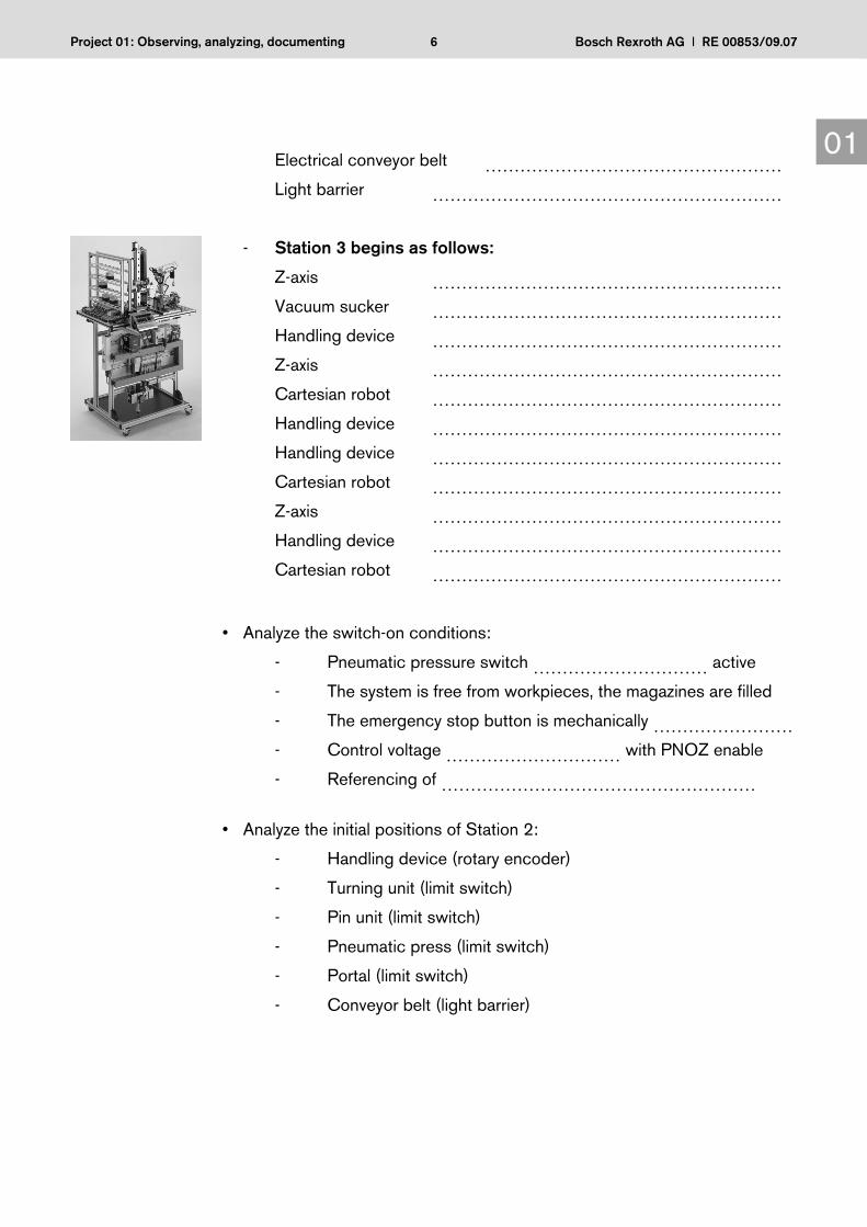
The trainee is to observe and analyze the Processing Station on the modular mechatronic system and understand it with the help of the documentation. The proper operation of the mMS and all its mechatronic functions are to be explored.
Project definition
In Station 2 – processing with pneumatic press the trainees observe and analyze functions with the L20 master program in the automatic and manual operating modes. The sensor and actuator components, function assemblies and the PLC control sequences are to be recognized, identified and checked in the documentation. Understanding the interdisciplinary interfaces forms the basis for any mechatronics knowledge.
Knowledge of electropneumatic and electrical components and IndraLogic control technology.
Fig. 01.01 Station 2 Processing
Observing, analyzing and documenting in the beginner's application for the mMS reality with Station 2
Prerequisites

2Project 01: Observing, analyzing, documenting Bosch Rexroth AG I RE 00853/09.07
01Project steps
Analysis of project documents:
• The operating instructions RE 09950-B describe safety in chapter 2 and the function of the Processing Station with pneumatic press in chapter 3.3.
• The electrical equipment is shown on the wiring diagram "Station 2 Process-ing" on page 3
• Pneumatic circuit diagrams of Station 2 Processing
• The equipment data sheets can be found on the CD-ROM "Technical docu-mentation".
• The functions of the equipment are described in the data sheets
• List of PLC inputs
(see Annex Global_variables_Station2.exp)
• List of PLC outputs
(see Annex Global_variables_Station2.exp)
• Operating and display functions of the control panel (see RE 09950)
Informing
Project handling steps:
• Read the operating instructions
• Commission the mMS with master L20 programs (trainer)
• Observe the functional sequence in the automatic operating mode
• Observe and control the functional sequence in the manual operating mode
• Analyze the switch-on conditions
• Analyze the initial position
• Analyze the interfaces between assembly modules
• Create a sequence table for Station 2
• Explain the sequence table
Planning

3Project 01: Observing, analyzing, documenting Bosch Rexroth AG I RE 00853/09.07
01
Aids:
• PC with CD-ROM "Technical documentation"
• IndraWorks
• IndraLogic
Sequence and interrelationships of steps:
• See Planning
Teamwork:
• Preferably 2 trainees together
Solution process:
• Observing
• Analyzing
• Understanding
• Documenting
Decision-making
Work instructions:
• Read the operating instructions mMS, chapters 5.3, 5.4
• Start up the mMS with master L20 programs (trainer)
Switch the power supply off with the main switch. Insert the compact flash cards with the master program into the relevant PLC L20 on the stations.
Station (1/3) Magazine
Station (2/3) Processing
Station (3/3) Storage
• Remove the terminating plugs on the stations. Plug connection cables W32, W21 between the stations and switch on the power supply.
• The three PLC L20 load the PLC program with the display showing
…………………… and change over to the status
…………………… →…………………… after approx. 2 minutes.
• Manually fill the Station 1 and 2 magazines and the pin magazine
Execution

4Project 01: Observing, analyzing, documenting Bosch Rexroth AG I RE 00853/09.07
01• The operating and display functions on the mMS control panel are:
Indicator lamps…………………… and…………………… (…………………) flash on 3 control panels, in addition, indicator lamps…………………… on Stations 2 and 3 are flashing. According to the operating instructions, the following operation is required:
3x button …………… → indicator lamp …………… is permanently ON,
Pressing buttons …………… and ………… on Stations 2 and 3 results in referencing of the handling device → indicator lamp …………… permanently ON.
Indicator lamps …………… and …………… go out
Indicator lamp …………… on Station 1 flashes
• Set the ……………(automatic) operating mode on three control panels:
Pressing the………………………………… button results in the start-up of the system in the automatic operating mode.
• Observe the functional sequence of Station 2 in the automatic operating mode (see sequence below, because the sequences partially coincide with those of Station 1 and Station 3).
• Observe and control the functional sequences in the automatic operating mode, with the "STOP"/"START" buttons being optionally activated in Station 2:
- Station 1 starts as follows:
Magazine 1 ……………………………………………………………
Conveyor belt ……………………………………………………………
Test cylinder …………………………………………………………… Conveyor belt ……………………………………………………………
Test unit ……………………………………………………………
Light barrier ……………………………………………………………
- Station 2 starts as follows:
Handling device ……………………………………………………
Vacuum sucker ……………………………………………………
Handling device ……………………………………………………
Handling device ……………………………………………………
Vacuum sucker ……………………………………………………
Turning unit ……………………………………………………

5Project 01: Observing, analyzing, documenting Bosch Rexroth AG I RE 00853/09.07
01 Handling device ……………………………………………………
Handling device ……………………………………………………
Feed cylinder ……………………………………………………
- Pin unit:
Handling device ……………………………………………………
Handling device ……………………………………………………
Handling device ……………………………………………………
Turning unit ……………………………………………………
Handling device ……………………………………………………
Handling device ……………………………………………………
Z-axis ……………………………………………………
Handling device ……………………………………………………
Handling device ……………………………………………………
Z-axis ……………………………………………………
Handling device ……………………………………………………
Handling device ……………………………………………………
Z-axis ……………………………………………………
Handling device ……………………………………………………
Handling device ……………………………………………………
Handling device ……………………………………………………
Z-axis ……………………………………………………
Handling device ……………………………………………………
Handling device ……………………………………………………
Handling device ……………………………………………………
Feed cylinder ……………………………………………………
Protective door ……………………………………………………
Press cylinder ……………………………………………………
Press cylinder ……………………………………………………
Feed cylinder ……………………………………………………
Portal ……………………………………………………
Vacuum sucker ……………………………………………………
Portal ……………………………………………………
Vacuum sucker ……………………………………………………
6Project 01: Observing, analyzing, documenting Bosch Rexroth AG I RE 00853/09.07
01 Electrical conveyor belt ……………………………………………
Light barrier ……………………………………………………
- Station 3 begins as follows:
Z-axis ……………………………………………………
Vacuum sucker ……………………………………………………
Handling device ……………………………………………………
Z-axis ……………………………………………………
Cartesian robot ……………………………………………………
Handling device ……………………………………………………
Handling device ……………………………………………………
Cartesian robot ……………………………………………………
Z-axis ……………………………………………………
Handling device ……………………………………………………
Cartesian robot ……………………………………………………
• Analyze the switch-on conditions:
- Pneumatic pressure switch ………………………… active
- The system is free from workpieces, the magazines are filled
- The emergency stop button is mechanically …………………… - Control voltage ………………………… with PNOZ enable
- Referencing of ………………………………………………
• Analyze the initial positions of Station 2:
- Handling device (rotary encoder)
- Turning unit (limit switch)
- Pin unit (limit switch)
- Pneumatic press (limit switch)
- Portal (limit switch)
- Conveyor belt (light barrier)

7Project 01: Observing, analyzing, documenting Bosch Rexroth AG I RE 00853/09.07
01• Analyze the mechanical, electrical interfaces between assembly modules:
- Magazines 1 and 2 with conveyor belt Station 1 (limit switch)
- Conveyor belt Station 1 with handling device Station 2 (light barrier)
- Handling device Station 2 with turning unit, pin unit, pneumatic press (rotary encoder)
- Portal with pneumatic press, conveyor belt Station 2 (limit switch)
- Conveyor belt Station 2 with handling device Station 3 (rotary encoder)
- Handling device Station 3 with Cartesian robot (rotary encoder)
The mMS operating instructions contain notes on machine safety and risks, which must be observed and followed by the trainee.
Read mMS operating instructions: - RE 09950-B - RE 09953-B
• Commission mMS (trainer) with power supply of pneumatics and electrical equipment - Check air pressure …………………………………………… - Check voltage supply …………………………………………… - Check control voltage …………………………………………… - Check L20 display: ……………………………………………
• Operating and indicator functions on the mMS control panel
- Indicator lamps "QUIT", "START", "STOP"
- Position/locking of emergency stop
- Operating mode selector switch: Automatic, manual
- Indicator lamp "S6"
Attention

8Project 01: Observing, analyzing, documenting Bosch Rexroth AG I RE 00853/09.07
01• Observe the functional sequences in the automatic operating mode with optionally active "STOP"/"START" push-button. Technical systems (see chapter 1.3 of manual "Mechatronics. Theory and Application")
- Material transport: ……………………………………………………
……………………………………………………………………………
……………………………………………………………………………
……………………………………………………………………………
……………………………………………………………………………
- Energy conversion: ……………………………………………………
……………………………………………………………………………
……………………………………………………………………………
……………………………………………………………………………
……………………………………………………………………………
- Information flow: ……………………………………………………
……………………………………………………………………………
……………………………………………………………………………
……………………………………………………………………………
…………………………………………………………………………… • Analyze the switch-on conditions
- For the first time, air pressure ON
- For the first time, network ON
- Emergency stop – control voltage ON – air pressure switch QX0.4
- Emergency stop – lock, release
• Analyze the interfaces between assembly modules
- Mechanical: Intervals, collision, transfer
- Pneumatic: Cylinders, valves, pressure lines
- Electrical: Motors, sensors, relays, separating points
- IT: Inputs, outputs, L2O

9Project 01: Observing, analyzing, documenting Bosch Rexroth AG I RE 00853/09.07
01
List the sequence of the individual steps of the handling device of Station 2 in tabular form. Skip over pin pressing and the turning required for the cube halves.
Sequence of the individual steps
Step Component ActionFirst cube half
1 Vertical cylinder (X-axis)
2 Ejector with suction cup
3 Vertical cylinder (X-axis)
4 Rotary drive
5 Vertical cylinder (X-axis)
6 Ejector with suction cup
7 Vertical cylinder (X-axis)
Intermediate steps: Turning cube half and press in pin
8 Vertical cylinder (X-axis)
9 Ejector with suction cup
10 Vertical cylinder (X-axis)
11 Rotary drive
12 Z-axis
13 Vertical cylinder (X-axis)
14 Ejector with suction cup
15 Vertical cylinder (X-axis)
16 Z-axis
17 Rotary drive
Second cube half
18 Vertical cylinder (X-axis)
19 Ejector with suction cup
20 Vertical cylinder (X-axis)
21 Rotary drive
22 Z-axis
23 Vertical cylinder (X-axis)
24 Ejector with suction cup
25 Vertical cylinder (X-axis)
26 Z-axis
27 Rotary drive
Table 01.01 Structure of the individual steps

10Project 01: Observing, analyzing, documenting Bosch Rexroth AG I RE 00853/09.07
01
• Intermediate results:
- Sequence table begins and ends in Station 2
- Compare the sequence table with the sequence of functions for the automatic mode
• Result/customer requirement:
- The sequence is explained and corresponds to the sequence of functions in the automatic mode
Checking
• Self-evaluation by the trainee:
- Is the sequence of Station 1 described as for the automatic mode?
- Is the sequence of Station 2 described as for the automatic mode?
- Is the sequence of Station 3 described as for the automatic mode?
- Is the sequence of the handling device correctly described?
Evaluating

11Project 01: Observing, analyzing, documenting Bosch Rexroth AG I RE 00853/09.07
01• Evaluation by the trainer:
- Is the sequence table of Station 2 correctly completed?
- Can the trainee explain the sequence correctly?
- Is the sequence table of the handling device correctly completed?

12Project 01: Observing, analyzing, documenting Bosch Rexroth AG I RE 00853/09.07
01Notes

1Project 02: Understanding basic technologies Bosch Rexroth AG I RE 00853/09.07
02
Project 02:
Project definition
In Station 2 – Processing, the trainees observe and analyze the measurements and testing of electrical variables in the installation of electrical and pneumatic assemblies and components. The technical data of sensors and actuators, as-sembly modules and the PLC control processes are to be identified and checked in the documentation. Understanding the interdisciplinary interfaces forms the basis for knowledge of mechatronics.
Knowledge of electropneumatic and electrical components, and IndraLogic control technology
Understanding basic technologies in the beginner's application for electrical systems/sensorics with Station 2
Project tasks
The trainees are to observe and analyze the basic electrical and sensor technol-ogy of the Processing Station on the modular mechatronic system with the aid of the documentation. The electrical and pneumatic installation of sensors and actuators for mMS function assemblies are to be explored.
Prerequisites
Fig. 02.01 Station 2 Processing


![Pensacola Journal. (Pensacola, Florida) 1907-05-17 [p 8].ufdcimages.uflib.ufl.edu/UF/00/07/59/11/00853/00370.pdf · INDUSTRY TH-EM fORGER Parker NEGRO HIGHER COURT GUILTY ... garment](https://static.fdocuments.us/doc/165x107/5aa743d27f8b9a294b8bd97c/pensacola-journal-pensacola-florida-1907-05-17-p-8-th-em-forger-parker-negro.jpg)