RDG180408050-01 EN 55015-2013 & EN 61547-2009 EMC Report
37
Note: This test report is prepared for the customer shown above and for the device described herein. It may not be duplicated or used in part without prior written consent from Bay Area Compliance Laboratories Corp. (Dongguan). EN 55015:2013 EN 61547:2009 EN 61000-3-2:2014 EN 61000-3-3:2013 TEST REPORT For Xicato Inc. 101 Daggett Drive San Jose, CA 95134 Tested Model:XLT5095273624A/01 Multiple Model: XLTBBCCDDEEFFF/XX Report Type: Original Report Product Type: LED Strip Light Report Number: RDG180408050-01 Report Date: 2018-04-20 Reviewed By: Jerry Zhang EMC Manager Test Laboratory: Bay Area Compliance Laboratories Corp. (Dongguan) No.69 Pulongcun, Puxinhu Industry Area, Tangxia, Dongguan, Guangdong, China Tel: +86-769-86858888 Fax: +86-769-86858891 www.baclcorp.com.cn
Transcript of RDG180408050-01 EN 55015-2013 & EN 61547-2009 EMC Report

Note: This test report is prepared for the customer shown above and for the device described herein. It may not be duplicated or used in part without prior written consent from Bay Area Compliance Laboratories Corp. (Dongguan).
EN 55015:2013 EN 61547:2009
EN 61000-3-2:2014 EN 61000-3-3:2013
TEST REPORT For
Xicato Inc.
101 Daggett Drive San Jose, CA 95134
Tested Model:XLT5095273624A/01 Multiple Model: XLTBBCCDDEEFFF/XX
Report Type:
Original Report
Product Type:
LED Strip Light
Report Number: RDG180408050-01
Report Date: 2018-04-20
Reviewed By: Jerry Zhang EMC Manager
Test Laboratory:
Bay Area Compliance Laboratories Corp. (Dongguan) No.69 Pulongcun, Puxinhu Industry Area, Tangxia, Dongguan, Guangdong, China Tel: +86-769-86858888 Fax: +86-769-86858891 www.baclcorp.com.cn

Bay Area Compliance Laboratories Corp. (Dongguan) Report No.: RDG180408050-01
EN 55015:2013&EN 61547:2009 Page 2 of 37 EN 61000-3-2:2014&EN 61000-3-3:2013
TABLE OF CONTENTS GENERAL INFORMATION ...................................................................................................................................... 4
PRODUCT DESCRIPTION FOR EQUIPMENT UNDER TEST (EUT) ................................................................... 4 OBJECTIVE ............................................................................................................................................................... 4 TEST METHODOLOGY ........................................................................................................................................... 4
SYSTEM TEST CONFIGURATION ......................................................................................................................... 5 DESCRIPTION OF TEST CONFIGURATION ......................................................................................................... 5 EQUIPMENT MODIFICATIONS ............................................................................................................................. 5 EUT EXERCISE SOFTWARE .................................................................................................................................. 5 BLOCK DIAGRAM OF TEST SETUP ...................................................................................................................... 5 TEST EQUIPMENT LIST .......................................................................................................................................... 6 ENVIRONMENTAL CONDITIONS ......................................................................................................................... 7
SUMMARY OF TEST RESULTS .............................................................................................................................. 8
1 – CONDUCTED EMISSIONS .................................................................................................................................. 9 MEASUREMENT UNCERTAINTY ......................................................................................................................... 9 TEST SYSTEM SETUP ............................................................................................................................................. 9 EMI TEST RECEIVER SETUP ............................................................................................................................... 10 TEST PROCEDURE ................................................................................................................................................ 10 CORRECTED AMPLITUDE & MARGIN CALCULATION ................................................................................. 10 TEST DATA ............................................................................................................................................................. 11
2 – RADIATED ELECTROMAGNETIC DISTURBANCES 9 KHZ TO 30 MHZ ............................................. 13 EUT SYSTEM SETUP ............................................................................................................................................. 13 EMI TEST RECEIVER SETUP ............................................................................................................................... 13 TEST DATA ............................................................................................................................................................. 14
3 – RADIATED ELECTROMAGNETIC DISTURBANCES 30 MHZ TO 300 MHZ ......................................... 17 MEASUREMENT UNCERTAINTY ....................................................................................................................... 17 TEST SYSTEM SETUP ........................................................................................................................................... 17 EMI TEST RECEIVER SETUP ............................................................................................................................... 18 TEST PROCEDURE ................................................................................................................................................ 18 CORRECTED AMPLITUDE & MARGIN CALCULATION ................................................................................. 18 TEST DATA ............................................................................................................................................................. 19
4 – ELECTROSTATIC DISCHARGES IEC 61000-4-2 ......................................................................................... 21 MEASUREMENT UNCERTAINTY ....................................................................................................................... 21 TEST SYSTEM SETUP ........................................................................................................................................... 21 TEST STANDARD .................................................................................................................................................. 21 TEST PROCEDURE ................................................................................................................................................ 22 TEST DATA ............................................................................................................................................................. 23
5 – RADIO-FREQUENCY ELECTROMAGNETIC FIELDS IEC 61000-4-3 ..................................................... 25 MEASUREMENT UNCERTAINTY ....................................................................................................................... 25 TEST SYSTEM SETUP ........................................................................................................................................... 25 TEST STANDARD .................................................................................................................................................. 26 TEST PROCEDURE ................................................................................................................................................ 26

Bay Area Compliance Laboratories Corp. (Dongguan) Report No.: RDG180408050-01
EN 55015:2013&EN 61547:2009 Page 3 of 37 EN 61000-3-2:2014&EN 61000-3-3:2013
TEST DATA ............................................................................................................................................................. 27
7 – FAST TRANSIENTS IEC 61000-4-4 .................................................................................................................. 28 MEASUREMENT UNCERTAINTY ....................................................................................................................... 28 TEST SYSTEM SETUP ........................................................................................................................................... 28 TEST STANDARD .................................................................................................................................................. 28 TEST PROCEDURE ................................................................................................................................................ 28 TEST DATA ............................................................................................................................................................. 29
8 – INJECTED CURRENTS (RADIO-FREQUENCY COMMON MODE) IEC 61000-4-6 ............................... 30 MEASUREMENT UNCERTAINTY ....................................................................................................................... 30 TEST SETUP ............................................................................................................................................................ 30 TEST STANDARD .................................................................................................................................................. 30 TEST PROCEDURE ................................................................................................................................................ 31 TEST DATA ............................................................................................................................................................. 32
EXHIBIT A – EUT PHOTOGRAPHS...................................................................................................................... 33
EXHIBIT B – TEST SETUP PHOTOGRAPHS ...................................................................................................... 34
DECLARATION LETTER ....................................................................................................................................... 37

Bay Area Compliance Laboratories Corp. (Dongguan) Report No.: RDG180408050-01
EN 55015:2013&EN 61547:2009 Page 4 of 37 EN 61000-3-2:2014&EN 61000-3-3:2013
GENERAL INFORMATION Product Description for Equipment under Test (EUT)
EUT Name: LED Strip Light EUT Model: XLT5095273624A/01
Mutiple Models: XLTBBCCDDEEFFF/XX Rated Input Voltage: 24Vdc,0.3A External Dimension: 500mm(L)* 10 mm(W)* 1.3 mm(H)
Serial Number: 180408050 EUT Received Date: 2018.04.12
Note: The series product, models XLT5095273624A/01, XLTBBCCDDEEFFF/XX are electrically identical, we selected XLT5095273624A/01for fully testing .The difference between them was explained in the attached declaration letter. Objective This report is prepared on behalf of Xicato Inc. in accordance with EN 55015:2013 Limits and methods of measurement of radio disturbance characteristics of electrical lighting and similar equipment; EN 61547:2009 Equipment for general lighting purposes – EMC immunity requirements; EN 61000-3-2:2014 Electromagnetic compatibility (EMC) – Part 3-2: Limits – Limits for harmonic current emissions (equipment input current ≤ 16 A per phase); EN 61000-3-3:2013 Electromagnetic compatibility (EMC)Part 3-3: Limits – Limitation of voltage changes, voltage fluctuations and flicker in public low-voltage supply systems, for equipment with rated current ≤ 16 A per phase and not subject to conditional connection. The objective is to determine the compliance of EUT with: EN 55015:2013 EN 61547:2009 EN 61000-3-2:2014 EN 61000-3-3:2013. Test Methodology All measurements contained in this report were conducted with EN 55015:2013 Limits and methods of measurement of radio disturbance characteristics of electrical lighting and similar equipment; EN 61547:2009 Equipment for general lighting purposes – EMC immunity requirements; EN 61000-3-2:2014 Electromagnetic compatibility (EMC) – Part 3-2: Limits – Limits for harmonic current emissions (equipment input current ≤ 16 A per phase); EN 61000-3-3:2013 Electromagnetic compatibility (EMC)Part 3-3: Limits – Limitation of voltage changes, voltage fluctuations and flicker in public low-voltage supply systems, for equipment with rated current ≤ 16 A per phase and not subject to conditional connection.

Bay Area Compliance Laboratories Corp. (Dongguan) Report No.: RDG180408050-01
EN 55015:2013&EN 61547:2009 Page 5 of 37 EN 61000-3-2:2014&EN 61000-3-3:2013
SYSTEM TEST CONFIGURATION Description of Test Configuration The EUT was test in On mode. Equipment Modifications No modification was made to the EUT. EUT Exercise Software No software was used for testing. Block Diagram of Test Setup

Bay Area Compliance Laboratories Corp. (Dongguan) Report No.: RDG180408050-01
EN 55015:2013&EN 61547:2009 Page 6 of 37 EN 61000-3-2:2014&EN 61000-3-3:2013
Test Equipment List
Manufacturer Description Model Serial Number Calibration Date Calibration Due Date
R&S EMI Test Receiver ESCS 30 830245/006 2017-12-11 2018-12-11 N/A Coaxial Cable C-NJNJ-50 C-0200-01 2017-09-05 2018-09-05 R&S Test Software EMC32 Version8.53.0 N/A N/A
R&S Two-line V-network ENV 216 101614 2017-12-08 2018-12-08
Pro instrument DC Power Supply pps3300 N/A N/A N/A
EVERFINE TRIPLE-LOOP antenna LLA-2 903002 2015-07-16 2018-07-16
Farad Test Software EZ-EMC V1.1.4.2 N/A N/A R&S EMI Test Receiver ESCI 100035 2017-08-04 2018-08-04
Sunol Sciences Antenna JB3 A060611-3 2017-07-21 2019-07-21 HP Amplifier 8447F 2443A01912 2017-09-05 2018-09-05 N/A Coaxial Cable C-NJNJ-50 C-0400-02 2017-09-05 2018-09-05 N/A Coaxial Cable C-NJNJ-50 C-0075-02 2017-09-05 2018-09-05 N/A Coaxial Cable C-NJNJ-50 C-2200-01 2017-09-05 2018-09-05 HP Signal Generator 8648A 3246A00831 2017-12-14 2018-12-14
R&S Power Amplifier 15A250 12934 N/A N/A NARDA Attenuator 769-6 2754 N/A N/A
COM-POWER CDN M325E 521064 2017-12-14 2018-12-14
EM TEST Ultra Compact Generator UCS500-M6 V6016101357 2018-01-04 2019-01-04
EM TEST Auto Transformer MV2616 0403-16 N/A N/A SCHAFFNER ESD Tester NSG435 005 101 2017-07-10 2018-07-10
HP Signal Generator 8665B 3438a00584 2017-07-18 2018-07-18 Sunol Sciences Antenna JB3 A060611-2 2017-08-25 2020-08-25
N/A Coaxial Cable C-NJNJ-50 C-1400-01 2017-05-06 2018-05-06 * Statement of Traceability: Bay Area Compliance Laboratories Corp. (Dongguan) attests that all calibrations have been performed, traceable to National Primary Standards and International System of Units (SI).

Bay Area Compliance Laboratories Corp. (Dongguan) Report No.: RDG180408050-01
EN 55015:2013&EN 61547:2009 Page 7 of 37 EN 61000-3-2:2014&EN 61000-3-3:2013
Environmental Conditions
Temperature: 24.8~27.3oC
Relative Humidity: 48~60%*
ATM Pressure: 100.5~ 101.1kPa
Tester: Jack Pan
Test Date: 2018.04.12-2018.04.16
Note: *The relative humidity of ESD test environment is 51%.

Bay Area Compliance Laboratories Corp. (Dongguan) Report No.: RDG180408050-01
EN 55015:2013&EN 61547:2009 Page 8 of 37 EN 61000-3-2:2014&EN 61000-3-3:2013
SUMMARY OF TEST RESULTS
SN Rule and Clause Description of Test Test Result
1 EN 55015 Clause 4.3.1 Conducted emissions Compliance
2 EN 55015 Clause 4.4.1
Radiated electromagnetic disturbances 9 kHz to 30 MHz Compliance
3 EN 55015 Clause 4.4.2
Radiated electromagnetic disturbances 30 MHz to 300 MHz Compliance
4 EN 61547 Clause 5.2 Electrostatic discharges IEC 61000-4-2 Compliance
5 EN 61547 Clause 5.3
Radio-frequency electromagnetic fields IEC 61000-4-3 Compliance
6 EN 61547 Clause 5.4
Power frequency magnetic fields IEC 61000-4-8 Not applicable*
7 EN 61547 Clause 5.5 Fast transients IEC 61000-4-4 Compliance
8 EN 61547 Clause 5.6
Injected currents (radio-frequency common mode) IEC 61000-4-6 Compliance
9 EN 61547 Clause 5.7 Surges IEC 61000-4-5 Not applicable***
10 EN 61547 Clause 5.8
Voltage dips and short interruptions IEC 61000-4-11 Not applicable***
11 EN 61000-3-2 Harmonic current emissions Not applicable** 12 EN 61000-3-3 Voltage fluctuations and flicker Not applicable***
Note: Not applicable*: The EUT is sensitive to magneticfield. Not applicable**:The EUT Power is less than 25W. Not applicable***: The EUT is DC 24V power supply.

Bay Area Compliance Laboratories Corp. (Dongguan) Report No.: RDG180408050-01
EN 55015:2013&EN 61547:2009 Page 9 of 37 EN 61000-3-2:2014&EN 61000-3-3:2013
1 – CONDUCTED EMISSIONS Measurement Uncertainty Compliance or non- compliance with a disturbance limit shall be determined in the following manner: If Ulab is less than or equal to Ucispr of Table 1, then: –compliance is deemed to occur if no measured disturbance level exceeds the disturbance limit; –non - compliance is deemed to occur if any measured disturbance level exceeds the disturbance limit. If Ulab is greater than Ucispr of Table 1, then: –compliance is deemed to occur if no measured disturbance level, increased by (Ulab − Ucispr), exceeds the disturbance limit; –non - compliance is deemed to occur if any measured disturbance level, increased by (Ulab − Ucispr), exceeds the disturbance limit. Based on CISPR 16-4-2: 2011, measurement uncertainty of conducted disturbance at mains port using AMN at Bay Area Compliance Laboratories Corp. (Dongguan) is 3.12 dB (150 kHz to 30 MHz).
Table 1 – Values of Ucispr
Measurement Ucispr Conducted disturbance at mains port using AMN (150 kHz to 30 MHz) 3.4 dB
Test System Setup

Bay Area Compliance Laboratories Corp. (Dongguan) Report No.: RDG180408050-01
EN 55015:2013&EN 61547:2009 Page 10 of 37 EN 61000-3-2:2014&EN 61000-3-3:2013
The setup of EUT is according with CISPR 16-1-1:2010+A1:2010, CISPR 16-2-1:2010 measurement procedure. The specification used was the EN 55015 limits. The external I/O cables were draped along the test table and formed a bundle 30 to 40 cm long in the middle. The power of EUT was connected to a 24V DC power source. EMI Test Receiver Setup The EMI Test Receiver was set to investigate the spectrum from 9 kHz to 30 MHz. During the conducted emission test, the EMI Test Receiver was set with the following configurations:
Frequency Range IF B/W
9 kHz – 150 kHz 200 Hz
150 kHz – 30 MHz 9 kHz
Test Procedure Maximizing procedure was performed on the six (6) highest emissions to ensure EUT compliance using all installation combination. All data was recorded in the Quasi-peak and average detection mode. Corrected Amplitude & Margin Calculation The basic equation is as follows: Result (QuasiPeak or Average) = Meter Reading + Corr. Note: Corr. = Cable loss + Factor of coupling device The “Margin” column of the following data tables indicates the degree of compliance within the applicable limit. For example, a margin of 7dB means the emission is 7dB below the maximum limit. The equation for margin calculation is as follows:
Margin = Limit – Result

Bay Area Compliance Laboratories Corp. (Dongguan) Report No.: RDG180408050-01
EN 55015:2013&EN 61547:2009 Page 11 of 37 EN 61000-3-2:2014&EN 61000-3-3:2013
Test Data Please refer to following table and plots: Model Number: XLT5095273624A/01 Port: L Test Mode: ON Power Source: DC 24V
0
20
40
60
80
100
120
140150
9k 20 30 50 100k 200 300 500 1M 2M 3M 5M 10M 20 30M
Leve
l in
dBμ
Frequency in Hz
EN55015_QPEN55015_AV
Final Result 1
Frequency (MHz)
QuasiPeak (dBμV)
Bandwidth (kHz)
Line Corr.(dB)
Margin(dB)
Limit(dBμV)
0.163741 45.7 9.000 L1 11.0 19.6 65.30.251783 39.5 9.000 L1 10.3 22.2 61.70.528270 29.9 9.000 L1 9.9 26.1 56.01.289541 22.1 9.000 L1 9.8 33.9 56.02.953456 15.7 9.000 L1 9.8 40.3 56.0
23.446008 20.6 9.000 L1 10.1 39.4 60.0
Final Result 2 Frequency
(MHz) Average (dBμV)
Bandwidth (kHz)
Line Corr.(dB)
Margin(dB)
Limit (dBμV)
0.153629 41.5 9.000 L1 11.1 14.3 55.80.240029 34.5 9.000 L1 10.4 17.6 52.10.528270 24.2 9.000 L1 9.9 21.8 46.01.190776 17.6 9.000 L1 9.8 28.4 46.03.000901 10.3 9.000 L1 9.8 35.8 46.0
19.676017 14.2 9.000 L1 10.1 35.8 50.0

Bay Area Compliance Laboratories Corp. (Dongguan) Report No.: RDG180408050-01
EN 55015:2013&EN 61547:2009 Page 12 of 37 EN 61000-3-2:2014&EN 61000-3-3:2013
Model Number: XLT5095273624A/01 Port: N Test Mode: ON Power Source: DC 24V
0
20
40
60
80
100
120
140150
9k 20 30 50 100k 200 300 500 1M 2M 3M 5M 10M 20 30M
Leve
l in
dBμ
Frequency in Hz
EN55015_QPEN55015_AV
Final Result 1
Frequency (MHz)
QuasiPeak (dBμV)
Bandwidth (kHz)
Line Corr.(dB)
Margin(dB)
Limit (dBμV)
0.153629 46.6 9.000 N 11.1 19.2 65.80.279263 38.2 9.000 N 10.2 22.6 60.80.572086 29.0 9.000 N 9.8 27.0 56.01.239175 22.3 9.000 N 9.8 33.7 56.03.024908 16.7 9.000 N 9.8 39.3 56.0
24.205331 14.8 9.000 N 10.1 45.2 60.0
Final Result 2 Frequency
(MHz) Average (dBμV)
Bandwidth (kHz)
Line Corr.(dB)
Margin(dB)
Limit (dBμV)
0.150000 41.5 9.000 N 11.2 14.5 56.00.243884 34.9 9.000 N 10.4 17.1 52.00.519918 25.6 9.000 N 9.9 20.4 46.01.171949 16.7 9.000 N 9.8 29.3 46.03.049107 10.5 9.000 N 9.8 35.5 46.0
24.205331 8.2 9.000 N 10.1 41.8 50.0

Bay Area Compliance Laboratories Corp. (Dongguan) Report No.: RDG180408050-01
EN 55015:2013&EN 61547:2009 Page 13 of 37 EN 61000-3-2:2014&EN 61000-3-3:2013
2 – RADIATED ELECTROMAGNETIC DISTURBANCES 9 KHZ TO 30 MHZ EUT System Setup EMI Test Receiver Setup During the radiated emission test, the EMI test receiver was set with the following configurations:
Frequency Range IF B/W
9 kHz – 150 kHz 200 Hz
150 kHz – 30 MHz 9 kHz
EUT

Bay Area Compliance Laboratories Corp. (Dongguan) Report No.: RDG180408050-01
EN 55015:2013&EN 61547:2009 Page 14 of 37 EN 61000-3-2:2014&EN 61000-3-3:2013
Test Data Please refer to following table and plots: Model Number: XLT5095273624A/01 Port: X Test Mode: ON Power Source: DC 24V
-30
-20 0
20
40
60
80
100
9k 20 30 50 100k 200 300 500 1M 2M 3M 5M 10M 20 30M
Leve
l in
dBμ
Frequency in Hz
EN55015 Radiated
Final Result 1
Frequency (MHz)
QuasiPeak (dBμA)
Bandwidth (kHz)
Triple Loop frame
Corr.(dB)
Margin(dB)
Limit(dBμA)
0.228823 33.7 9.000 X -15.2 19.2 52.90.419276 26.9 9.000 X -15.5 18.7 45.60.468757 28.2 9.000 X -15.5 16.1 44.30.491712 26.0 9.000 X -15.5 17.7 43.70.515791 23.9 9.000 X -15.5 19.3 43.22.883693 4.9 9.000 X -15.4 17.6 22.5

Bay Area Compliance Laboratories Corp. (Dongguan) Report No.: RDG180408050-01
EN 55015:2013&EN 61547:2009 Page 15 of 37 EN 61000-3-2:2014&EN 61000-3-3:2013
Model Number: XLT5095273624A/01 Port: Y Test Mode: ON Power Source: DC 24V
-30
-20 0
20
40
60
80
100
9k 20 30 50 100k 200 300 500 1M 2M 3M 5M 10M 20 30M
Leve
l in
dBμ
Frequency in Hz
EN55015 Radiated
Final Result 1
Frequency (MHz)
QuasiPeak (dBμA)
Bandwidth (kHz)
Triple Loop frame
Corr.(dB)
Margin(dB)
Limit (dBμA)
0.655073 29.3 9.000 Y -15.6 11.0 40.30.756101 28.8 9.000 Y -15.7 9.8 38.60.831967 28.7 9.000 Y -15.8 8.7 37.40.845331 26.7 9.000 Y -15.8 10.5 37.22.558827 16.7 9.000 Y -15.7 7.2 23.92.977084 16.9 9.000 Y -15.8 5.2 22.1

Bay Area Compliance Laboratories Corp. (Dongguan) Report No.: RDG180408050-01
EN 55015:2013&EN 61547:2009 Page 16 of 37 EN 61000-3-2:2014&EN 61000-3-3:2013
Model Number: XLT5095273624A/01 Port: Z Test Mode: ON Power Source: DC 24V
-30
-20 0
20
40
60
80
100
9k 20 30 50 100k 200 300 500 1M 2M 3M 5M 10M 20 30M
Leve
l in
dBμ
Frequency in Hz
EN55015 Radiated
Final Result 1
Frequency (MHz)
QuasiPeak (dBμA)
Bandwidth (kHz)
Triple Loop frame
Corr.(dB)
Margin(dB)
Limit (dBμA)
0.687153 22.6 9.000 Z -15.8 17.1 39.70.780588 22.0 9.000 Z -15.9 16.2 38.20.799472 22.1 9.000 Z -15.9 15.8 37.91.289541 13.0 9.000 Z -15.8 19.1 32.12.558827 15.9 9.000 Z -15.8 8.0 23.92.684134 10.5 9.000 Z -15.8 12.8 23.3

Bay Area Compliance Laboratories Corp. (Dongguan) Report No.: RDG180408050-01
EN 55015:2013&EN 61547:2009 Page 17 of 37 EN 61000-3-2:2014&EN 61000-3-3:2013
3 – RADIATED ELECTROMAGNETIC DISTURBANCES 30 MHZ TO 300 MHZ Measurement Uncertainty Compliance or non- compliance with a disturbance limit shall be determined in the following manner: If Ulab is less than or equal to Ucispr of Table 1, then: –compliance is deemed to occur if no measured disturbance level exceeds the disturbance limit; –non - compliance is deemed to occur if any measured disturbance level exceeds the disturbance limit. If Ulab is greater than Ucispr of Table 1, then: –compliance is deemed to occur if no measured disturbance level, increased by (Ulab − Ucispr), exceeds the disturbance limit; –non - compliance is deemed to occur if any measured disturbance level, increased by (Ulab − Ucispr), exceeds the disturbance limit. Based on CISPR 16-4-2: 2011, measurement uncertainty of radiated emission at a distance of 10m at Bay Area Compliance Laboratories Corp. (Dongguan) is:30M~200MHz: 4.55 dB for Horizontal, 4.57 dB for Vertical; 200M~1GHz: 4.66 dB for Horizontal, 4.56 dB for Vertical; measurement uncertainty of radiated emission at a distance of 3m at Bay Area Compliance Laboratories Corp. (Dongguan) is:30M~200MHz: 4.58 dB for Horizontal, 4.59 dB for Vertical; 200M~1GHz: 4.83 dB for Horizontal, 5.85 dB for Vertical; 1G~6GHz: 4.45 dB, 6G~18GHz: 5.23 dB.
Table 1 – Values of Ucispr
Measurement Ucispr
Radiated disturbance (electric field strength at an OATS or in a SAC) (30 MHz to 1000 MHz) Radiated disturbance (electric field strength in a FAR) (1 GHz to 6 GHz) Radiated disturbance (electric field strength in a FAR) (6 GHz to 18 GHz)
6.3 dB5.2 dB5.5 dB
Test System Setup

Bay Area Compliance Laboratories Corp. (Dongguan) Report No.: RDG180408050-01
EN 55015:2013&EN 61547:2009 Page 18 of 37 EN 61000-3-2:2014&EN 61000-3-3:2013
The radiated emission tests were performed in the 10 meters chamber test site, using the setup accordance with the CISPR 16-1-1:2010+A1:2010, CISPR16-2-3:2010. The specification used was EN 55015. The external I/O cables were draped along the test table and formed a bundle 30 to 40 cm long in the middle. The power was connected to 24V DC power source. EMI Test Receiver Setup The system was investigated from 30 MHz to 300 MHz. During the radiated emission test, the EMI test receiver was set with the following configurations:
Frequency Range RBW Video B/W IF B/W Detector
30MHz – 300 MHz 120 kHz 300 kHz 120kHz QP Test Procedure Maximizing procedure was performed on the highest emissions to ensure that the EUT complied with all installation combinations. All data was recorded in the Quasi-peak detection mode. Corrected Amplitude & Margin Calculation The basic equation is as follows: Result = Meter Reading+ Corrected Note: Corrected = Antenna Factor + Cable Loss - Amplifier Gain or Corrected = Antenna Factor + Cable Loss + Insertion loss of attenuator - Amplifier Gain The “Margin” column of the following data tables indicates the degree of compliance with the applicable limit. For example, a margin of 7 dB means the emission is 7 dB below the limit. The equation for margin calculation is as follows:
Margin = Limit – Result

Bay Area Compliance Laboratories Corp. (Dongguan) Report No.: RDG180408050-01
EN 55015:2013&EN 61547:2009 Page 19 of 37 EN 61000-3-2:2014&EN 61000-3-3:2013
Test Data Please refer to following table and plots: Condition: EN55015 10m Radiation Polarization: Horizontal EUT: LED Strip Light Power: DC 24V Model: XLT5095273624A/01 Distance: 10m Test Mode: On Note:
No. Frequency Reading Detector Corrected Result Limit Margin (MHz) (dBμV) dB/m (dBμV/m) (dBμV/m) (dB)
1 30.0000 27.11 QP -7.91 19.20 30.00 10.80 2 37.8300 26.91 QP -11.71 15.20 30.00 14.80 3 95.0700 30.84 QP -18.14 12.70 30.00 17.30 4 107.4900 28.32 QP -17.12 11.20 30.00 18.80 5 137.4600 27.36 QP -12.86 14.50 30.00 15.50 6 197.9400 26.30 QP -13.10 13.20 30.00 16.80

Bay Area Compliance Laboratories Corp. (Dongguan) Report No.: RDG180408050-01
EN 55015:2013&EN 61547:2009 Page 20 of 37 EN 61000-3-2:2014&EN 61000-3-3:2013
Condition: EN55015 10m Radiation Polarization: Vertical EUT: LED Strip Light Power: DC 24V Model: XLT5095273624A/01 Distance: 10m Test Mode: On Note:
No. Frequency Reading Detector Corrected Result Limit Margin (MHz) (dBμV) dB/m (dBμV/m) (dBμV/m) (dB)
1 31.0800 27.65 QP -8.45 19.20 30.00 10.80 2 46.2000 29.90 QP -16.70 13.20 30.00 16.80 3 91.8300 28.67 QP -18.47 10.20 30.00 19.80 4 145.8300 27.70 QP -12.80 14.90 30.00 15.10 5 167.7000 26.40 QP -12.90 13.50 30.00 16.50 6 198.7500 25.59 QP -12.99 12.60 30.00 17.40

Bay Area Compliance Laboratories Corp. (Dongguan) Report No.: RDG180408050-01
EN 55015:2013&EN 61547:2009 Page 21 of 37 EN 61000-3-2:2014&EN 61000-3-3:2013
4 – ELECTROSTATIC DISCHARGES IEC 61000-4-2 Measurement Uncertainty Ulab (measurement uncertainty of lab) and UEN (measurement uncertainty of EN 61000-4-2) please refer to the following:
Parameter UEN Ulab Rise time tr ≤15% 15%
Peak current Ip ≤7% 6.30% Current at 30 ns ≤7% 6.30% Current at 60 ns ≤7% 6.30%
Test System Setup IEC 61000-4-2 specifies that a tabletop EUT shall be placed on a non-conducting table which is 80 centimeters above a ground reference plane and that floor mounted equipment shall be placed on a insulating support approximately 10 centimeters above a ground plane. During the tests, the EUT is positioned over a ground reference plane in conformance with this requirement. For tabletop equipment, a 1.6 by 0.8-meter metal sheet (HCP) is placed on the table and connected to the ground plane via a metal strap with two 470 k Ohms resistors in series. The EUT and attached cables are isolated from this metal sheet by 0.5-millimeter thick insulating material. A Vertical Coupling Plane (VCP) grounded on the ground plane through the same configuration as in the HCP is used. Test Standard
EN 61547:2009 (IEC 61000-4-2:2008) Test level 3 for Air Discharges at ±8 kV Test level 2 for Contact Discharges at ±4 kV
EUT System
ESD Tester
Wooden Table
Remark: is the tip of the electrode
80 cm

Bay Area Compliance Laboratories Corp. (Dongguan) Report No.: RDG180408050-01
EN 55015:2013&EN 61547:2009 Page 22 of 37 EN 61000-3-2:2014&EN 61000-3-3:2013
Test Level
Level Test Voltage Contact Discharges (±kV)
Test Voltage Air Discharges (±kV)
1. 2 2 2. 4 4 3. 6 84. 8 15 X. Special Special
Performance criterion: B
Test Procedure
Air Discharges:
This test is done on a non-conductive surface. The round Discharges tip of the Discharges electrode shall be approached as fast as possible to touch the EUT. After each Discharges, the Discharges electrode shall be removed from the EUT. The generator is then re-triggered for a new single Discharges and repeated 10 times for each pre-selected test point. This procedure shall be repeated until all the air Discharges completed.
Contact Discharges:
All the procedure shall be same as Section 8.3.1 of IEC 61000-4-2, except that the tip of the Discharges electrode shall touch the EUT before the Discharges switch is operated.
Indirect Discharges for horizontal coupling plane
At least 20 single Discharges shall be applied to the horizontal coupling plane, at points on each side of the EUT. The Discharges electrode positions vertically at a distance of 0.1 m from the EUT and with the Discharges electrode touching the coupling plane.
Indirect Discharges for vertical coupling plane
At least 20 single Discharges shall be applied to the center of one vertical edge of the coupling plane. The coupling plane, of dimensions 0.5m X 0.5m, is placed parallel to, and positioned at a distance of 0.1m from the EUT. Discharges shall be applied to the coupling plane, with this plane in sufficient different positions that the four faces of the EUT are completely illuminated.

Bay Area Compliance Laboratories Corp. (Dongguan) Report No.: RDG180408050-01
EN 55015:2013&EN 61547:2009 Page 23 of 37 EN 61000-3-2:2014&EN 61000-3-3:2013
Test Data Please refer to following tables: Test Mode: On Note: Table 1: Electrostatic Discharge Immunity (Air Discharge)
Test Points Location Test Levels -2 kV +2 kV -4 kV +4 kV -8 kV +8 kV -15 kV +15 kV
/ / / / / / / / / Table 2: Electrostatic Discharge Immunity (Direct Contact)
Test Points Location Test Levels -2 kV +2 kV -4 kV +4 kV -6 kV +6 kV -8 kV +8 kV
/ / / / / / / / / Table 3: Electrostatic Discharge Immunity (Indirect Contact HCP)
Test Points Location Test Levels -2 kV +2 kV -4 kV +4 kV -6 kV +6 kV -8 kV +8 kV
Front Side A A A A / / / / Back Side A A A A / / / / Left Side A A A A / / / / Right Side A A A A / / / /
Table 4: Electrostatic Discharge Immunity (Indirect Contact VCP)
Test Points Location Test Levels -2 kV +2 kV -4 kV +4 kV -6 kV +6 kV -8 kV +8 kV
Front Side A A A A / / / / Back Side A A A A / / / / Left Side A A A A / / / / Right Side A A A A / / / /

Bay Area Compliance Laboratories Corp. (Dongguan) Report No.: RDG180408050-01
EN 55015:2013&EN 61547:2009 Page 24 of 37 EN 61000-3-2:2014&EN 61000-3-3:2013
Test Setup Photo

Bay Area Compliance Laboratories Corp. (Dongguan) Report No.: RDG180408050-01
EN 55015:2013&EN 61547:2009 Page 25 of 37 EN 61000-3-2:2014&EN 61000-3-3:2013
5 – RADIO-FREQUENCY ELECTROMAGNETIC FIELDS IEC 61000-4-3 Measurement Uncertainty Ulab (measurement uncertainty of lab) and UEN (measurement uncertainty of EN 61000-4-3) please refer to the following:
Parameter UEN Ulab Calibration process 1.88 dB 1.88 dB
Level setting 2.19 dB 2.19 dB Test System Setup
3m EUT
System
80 cm
Anechoic Chamber
Power Amplifier
Signal Generator
Wooden table
Bay Area Compliance Laboratories Corp. (Dongguan) Report No.: RDG180408050-01
EN 55015:2013&EN 61547:2009 Page 26 of 37 EN 61000-3-2:2014&EN 61000-3-3:2013
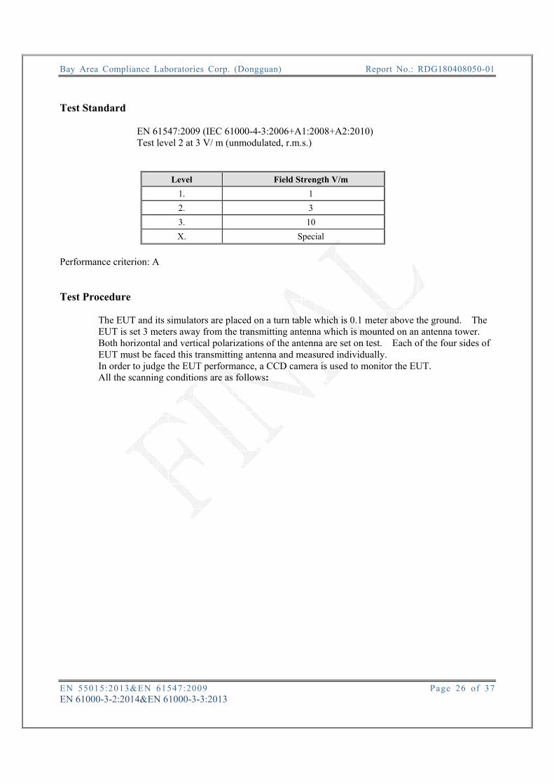
Test Standard
EN 61547:2009 (IEC 61000-4-3:2006+A1:2008+A2:2010) Test level 2 at 3 V/ m (unmodulated, r.m.s.)
Level Field Strength V/m 1. 1 2. 3 3. 10 X. Special
Performance criterion: A Test Procedure
The EUT and its simulators are placed on a turn table which is 0.1 meter above the ground. The EUT is set 3 meters away from the transmitting antenna which is mounted on an antenna tower. Both horizontal and vertical polarizations of the antenna are set on test. Each of the four sides of EUT must be faced this transmitting antenna and measured individually. In order to judge the EUT performance, a CCD camera is used to monitor the EUT. All the scanning conditions are as follows:

Bay Area Compliance Laboratories Corp. (Dongguan) Report No.: RDG180408050-01
EN 55015:2013&EN 61547:2009 Page 27 of 37 EN 61000-3-2:2014&EN 61000-3-3:2013
Test Data Please refer to following tables: Test Mode: On Note:
Condition of Test Remarks Field Strength 3 V/m (Test Level 2)
RF Signal 1 kHz, 80% AM, sine wave Sweep Frequency Step 1%, logarithmic
Dwell Time 1 Sec Frequency
Range (MHz)
Front Side Rear Side Left Side Right Side VERT HORI VERT HORI VERT HORI VERT HORI
80-1000 A A A A A A A A
Test Setup Photo

Bay Area Compliance Laboratories Corp. (Dongguan) Report No.: RDG180408050-01
EN 55015:2013&EN 61547:2009 Page 28 of 37 EN 61000-3-2:2014&EN 61000-3-3:2013
7 – FAST TRANSIENTS IEC 61000-4-4 Measurement Uncertainty Ulab (measurement uncertainty of lab) and UEN (measurement uncertainty of EN 61000-4-4) please refer to the following:
Parameter UEN Ulab Rise time tr 6.20% 6.20%
Peak voltage value Vp 8.60% 8.60% Voltage pulse width tw 5.90% 5.90%
Test System Setup Test Standard
EN 61547:2009 (IEC 61000-4-4:2004) Test Level 2 at 1.0 kV
Open Circuit Output Test Voltage ±10%
Level On Power Supply Lines On I/O (Input/Output) Signal data and control lines
1 0.5 kV 0.25 kV 2 1 kV 0.5 kV 3 2 kV 1 kV 4 4 kV 2 kV X Special Special
Performance criterion: B Test Procedure The EUT was arranged for Power Line Coupling and for I/O Line Coupling through a capacitive clamp, where applicable. (Note: The I/O coupling test using a capacitive clamp is performed on the I/O interface cables that are longer in length than 3 meters.) A metal ground plane 2.4 meter by 2.0 meter was placed between the floor and the table and is connected to the earth by a 2.0 meter ground rod. The ground rod is connected to the test facility’s electrical earth.

Bay Area Compliance Laboratories Corp. (Dongguan) Report No.: RDG180408050-01
EN 55015:2013&EN 61547:2009 Page 29 of 37 EN 61000-3-2:2014&EN 61000-3-3:2013
Test Data Test Mode: On Note: B:The lights would blink during the test, but the light
could be automatically restored and work normally after test finished.
Test Points Test Levels (kV)
+0.5 -0.5 +1.0 -1.0 +2.0 -2.0 +4.0 -4.0
AC mains power
input ports
L B B / / / / / /
N B B / / / / / /
Earth / / / / / / / /
L+N B B / / / / / /
L + Earth / / / / / / / /
N + Earth / / / / / / / /
L+N+Earth / / / / / / / /
Signal ports / / / / / / / / /
AC Port Test Setup Photo

Bay Area Compliance Laboratories Corp. (Dongguan) Report No.: RDG180408050-01
EN 55015:2013&EN 61547:2009 Page 30 of 37 EN 61000-3-2:2014&EN 61000-3-3:2013
8 – INJECTED CURRENTS (RADIO-FREQUENCY COMMON MODE) IEC 61000-4-6 Measurement Uncertainty Ulab (measurement uncertainty of lab) and UEN (measurement uncertainty of EN 61000-4-6) please refer to the following:
Parameter UEN Ulab CDN calibration process 1.27 dB 1.27 dB
CDN test process 1.36 dB 1.36 dB Test setup 10 cm Test Standard
EN 61547: 2009 (IEC 61000-4-6:2009) Test Level 2 at 3 V r.m.s. (unmodulated), 0.15 MHz ~ 80 MHz
Level Voltage Level (r.m.s.) V 1 1 2 3 3 10 X Special
Performance criterion: A
Wooden Table SG
CDN EUT

Bay Area Compliance Laboratories Corp. (Dongguan) Report No.: RDG180408050-01
EN 55015:2013&EN 61547:2009 Page 31 of 37 EN 61000-3-2:2014&EN 61000-3-3:2013
Test Procedure 1) Let the EUT work in test mode and test it. 2) The EUT are placed on an insulating support 0.1 m high above a ground reference plane.
CDN (coupling and decoupling device) is placed on the ground plane about 0.3 m from EUT. Cables between CDN and EUT are as short as possible, and their height above the ground reference plane shall be between 30 and 50 mm (where possible).
3) The disturbance signal described below is injected to EUT through CDN. 4) The EUT operates within its operational mode(s) under intended climatic conditions after power on. 5) The frequency range is swept from 150 kHz to 80 MHz using 3V signal level, and with the disturbance signal 80% amplitude modulated with a 1 kHz sine wave. 6) Where the frequency is swept incrementally, the step size shall not exceed 1 % of the preceding frequency value. The dwell time of the amplitude modulated carrier at each frequency shall not be less than the time necessary for the EUT to be exercised and to respond, but shall in no case be less than 0.5 s. 7) Recording the EUT operating situation during compliance testing and decide the EUT immunity criterion.

Bay Area Compliance Laboratories Corp. (Dongguan) Report No.: RDG180408050-01
EN 55015:2013&EN 61547:2009 Page 32 of 37 EN 61000-3-2:2014&EN 61000-3-3:2013
Test Data Test Mode: On Note: Table 1: AC mains power input port Frequency range: 150 kHz to 80 MHz
■Modulated: Amplitude 80%, 1kHz sine wave □ Unmodulated □ Other: Severity Level: 3 V Un modulated , r.m.s
Level Voltage Level (e.m.f.) U0
Pass Fail
1 1 / / 2 3 A / 3 10 / / X Special / /
AC Port Test Setup Photo

Bay Area Compliance Laboratories Corp. (Dongguan) Report No.: RDG180408050-01
EN 55015:2013&EN 61547:2009 Page 33 of 37 EN 61000-3-2:2014&EN 61000-3-3:2013
EXHIBIT A – EUT PHOTOGRAPHS
EUT – Top View
EUT – Bottom View

Bay Area Compliance Laboratories Corp. (Dongguan) Report No.: RDG180408050-01
EN 55015:2013&EN 61547:2009 Page 34 of 37 EN 61000-3-2:2014&EN 61000-3-3:2013
EXHIBIT B – TEST SETUP PHOTOGRAPHS
CE Front View
CE Side View

Bay Area Compliance Laboratories Corp. (Dongguan) Report No.: RDG180408050-01
EN 55015:2013&EN 61547:2009 Page 35 of 37 EN 61000-3-2:2014&EN 61000-3-3:2013
RE(Magnetic) View
RE Below 1G Front View

Bay Area Compliance Laboratories Corp. (Dongguan) Report No.: RDG180408050-01
EN 55015:2013&EN 61547:2009 Page 36 of 37 EN 61000-3-2:2014&EN 61000-3-3:2013
RE Below 1G Rear View

Bay Area Compliance Laboratories Corp. (Dongguan) Report No.: RDG180408050-01
EN 55015:2013&EN 61547:2009 Page 37 of 37 EN 61000-3-2:2014&EN 61000-3-3:2013
DECLARATION LETTER
*****END OF REPORT*****