RCP4 Stopper Cylinder Operation Manual
64
IAI America, Inc. RCP4 Stopper Cylinder Operation Manual Fourth Edition ST4525E ST68E, ST615E
Transcript of RCP4 Stopper Cylinder Operation Manual

IAI America, Inc.
RCP4 Stopper Cylinder Operation Manual
Fourth Edition
ST4525EST68E, ST615E


Please Read Before Use Thank you for purchasing our product.
This Operation Manual describes all necessary information items to operate this product safely such as the operation procedure, structure and maintenance procedure. Before the operation, read this manual carefully and fully understand it to operate this product safely. The enclosed DVD in this product package includes the Operation Manual for this product. For the operation of this product, print out the necessary sections in the Operation Manual or display them using the personal computer.
After reading through this manual, keep this Operation Manual at hand so that the operator of this product can read it whenever necessary.
[Important] This Operation Manual is original. The product cannot be operated in any way unless expressly specified in this Operation Manual. IAI shall assume no responsibility for the outcome of any operation not specified herein.
Information contained in this Operation Manual is subject to change without notice for the purpose of product improvement.
If you have any question or comment regarding the content of this manual, please contact the IAI sales office near you.
Using or copying all or part of this Operation Manual without permission is prohibited. The company names, names of products and trademarks of each company shown in the sentences are registered trademarks.


Table of Contents
Safety Guide·································································································· 1 Precautions in Operation ·················································································· 8 International Standards Compliances ·································································11 Name for Each Parts ······················································································13
1. Specifications Check ................................................................... 141.1 Product Check ...................................................................................................14
1.1.1 Parts ........................................................................................................................141.1.2 Teaching Tool...........................................................................................................141.1.3 Operation Manuals Related to This Product, which are Contained in the
Operation Manual (DVD).........................................................................................151.1.4 How to Read the Model Plate..................................................................................151.1.5 How to Read the Model ...........................................................................................16
1.2 Specifications .....................................................................................................171.2.1 Actuator ...................................................................................................................17
1.3 Option ................................................................................................................191.4 Motor • Encoder Cables .....................................................................................21
1.4.1 Model ST4525E.......................................................................................................21 1.4.2 Model ST68E, ST615E............................................................................................23
2. Installation ................................................................................... 252.1 Transportation ....................................................................................................25
2.1.1 Handling the Packed Unit ........................................................................................252.1.2 Handling the Actuator After Unpacking....................................................................25
2.2 Installation and Preservation Environment ........................................................262.2.1 Installation Environment ..........................................................................................262.2.2 Storage • Preservation Environment .......................................................................26
2.3 How to Install .....................................................................................................272.3.1 Installation Posture ..................................................................................................272.3.2 Installation................................................................................................................28
3. Connecting with the Controller .................................................... 33
4. Maintenance Inspection .............................................................. 384.1 Inspection Items and Schedule..........................................................................384.2 External Visual Inspection..................................................................................384.3 Cleaning.............................................................................................................384.4 Grease and Oil Supply.......................................................................................39
4.4.1 Applied Grease and Oil ...........................................................................................394.4.2 Grease and Oil Supply ............................................................................................404.4.3 How to Replace Maintenance (Consumable) Parts ................................................44
4.5 How to Change D-cut Direction on Model Code ST4525E ................................47
5. Life of the Shock Absorber .......................................................... 48
6. External Dimensions ................................................................... 496.1 RCP4-ST4525E .................................................................................................49
6.1.1 Counter Bored Type (Standard)...............................................................................496.1.2 Tapped Type (Option : Model AHT) .........................................................................50
6.2 RCP4-ST68E, ST615E ......................................................................................51

7. Warranty...................................................................................... 537.1 Warranty Period .................................................................................................537.2 Scope of the Warranty .......................................................................................537.3 Honoring the Warranty .......................................................................................537.4 Limited Liability ..................................................................................................537.5 Conditions of Conformance with Applicable Standards/Regulations,
Etc., and Applications ........................................................................................547.6 Other Items Excluded from Warranty.................................................................54
Change History ................................................................................. 55

1
Safety Guide“Safety Guide” has been written to use the machine safely and so prevent personal injury or property damage beforehand. Make sure to read it before the operation of this product.
Safety Precautions for Our Products The common safety precautions for the use of any of our robots in each operation.
No. OperationDescription Description
1 Model Selection
This product has not been planned and designed for the application where high level of safety is required, so the guarantee of the protection of human life is impossible. Accordingly, do not use it in any of the following applications. 1) Medical equipment used to maintain, control or otherwise affect
human life or physical health. 2) Mechanisms and machinery designed for the purpose of moving or
transporting people (For vehicle, railway facility or air navigation facility)
3) Important safety parts of machinery (Safety device, etc.) Do not use the product outside the specifications. Failure to do so may considerably shorten the life of the product.
Do not use it in any of the following environments. 1) Location where there is any inflammable gas, inflammable object or
explosive2) Place with potential exposure to radiation 3) Location with the ambient temperature or relative humidity exceeding
the specification range 4) Location where radiant heat is added from direct sunlight or other
large heat source 5) Location where condensation occurs due to abrupt temperature
changes 6) Location where there is any corrosive gas (sulfuric acid or
hydrochloric acid) 7) Location exposed to significant amount of dust, salt or iron powder 8) Location subject to direct vibration or impact
For an actuator used in vertical orientation, select a model which is equipped with a brake. If selecting a model with no brake, the moving part may drop when the power is turned OFF and may cause an accident such as an injury or damage on the work piece.

2
No. OperationDescription Description
2 Transportation When carrying a heavy object, do the work with two or more persons or utilize equipment such as crane.
When the work is carried out with 2 or more persons, make it clear who is to be the leader and who to be the follower(s) and communicate well with each other to ensure the safety of the workers.
When in transportation, consider well about the positions to hold, weight and weight balance and pay special attention to the carried object so it would not get hit or dropped.
Transport it using an appropriate transportation measure. The actuators available for transportation with a crane have eyebolts attached or there are tapped holes to attach bolts. Follow the instructions in the operation manual for each model.
Do not step or sit on the package. Do not put any heavy thing that can deform the package, on it. When using a crane capable of 1t or more of weight, have an operator who has qualifications for crane operation and sling work.
When using a crane or equivalent equipments, make sure not to hang a load that weighs more than the equipment’s capability limit.
Use a hook that is suitable for the load. Consider the safety factor of the hook in such factors as shear strength.
Do not get on the load that is hung on a crane. Do not leave a load hung up with a crane. Do not stand under the load that is hung up with a crane.
3 Storage and Preservation
The storage and preservation environment conforms to the installation environment. However, especially give consideration to the prevention of condensation.
Store the products with a consideration not to fall them over or drop due to an act of God such as earthquake.
4 Installation and Start
(1) Installation of Robot Main Body and Controller, etc. Make sure to securely hold and fix the product (including the work part). A fall, drop or abnormal motion of the product may cause a damage or injury. Also, be equipped for a fall-over or drop due to an act of God such as earthquake.
Do not get on or put anything on the product. Failure to do so may cause an accidental fall, injury or damage to the product due to a drop of anything, malfunction of the product, performance degradation, or shortening of its life.
When using the product in any of the places specified below, provide a sufficient shield. 1) Location where electric noise is generated 2) Location where high electrical or magnetic field is present 3) Location with the mains or power lines passing nearby 4) Location where the product may come in contact with water, oil or
chemical droplets

3
No. OperationDescription Description
(2) Cable Wiring Use our company’s genuine cables for connecting between the actuator and controller, and for the teaching tool.
Do not scratch on the cable. Do not bend it forcibly. Do not pull it. Do not coil it around. Do not insert it. Do not put any heavy thing on it. Failure to do so may cause a fire, electric shock or malfunction due to leakage or continuity error.
Perform the wiring for the product, after turning OFF the power to the unit, so that there is no wiring error.
When the direct current power (+24V) is connected, take the great care of the directions of positive and negative poles. If the connection direction is not correct, it might cause a fire, product breakdown or malfunction.
Connect the cable connector securely so that there is no disconnection or looseness. Failure to do so may cause a fire, electric shock or malfunction of the product.
Never cut and/or reconnect the cables supplied with the product for the purpose of extending or shortening the cable length. Failure to do so may cause the product to malfunction or cause fire.
4 Installation and Start
(3) Grounding The grounding operation should be performed to prevent an electric shock or electrostatic charge, enhance the noise-resistance ability and control the unnecessary electromagnetic radiation.
For the ground terminal on the AC power cable of the controller and the grounding plate in the control panel, make sure to use a twisted pair cable with wire thickness 0.5mm2 (AWG20 or equivalent) or more for grounding work. For security grounding, it is necessary to select an appropriate wire thickness suitable for the load. Perform wiring that satisfies the specifications (electrical equipment technical standards).
Perform Class D Grounding (former Class 3 Grounding with ground resistance 100 or below).

4
No. OperationDescription Description
4 Installation and Start
(4) Safety Measures When the work is carried out with 2 or more persons, make it clear who is to be the leader and who to be the follower(s) and communicate well with each other to ensure the safety of the workers.
When the product is under operation or in the ready mode, take the safety measures (such as the installation of safety and protection fence) so that nobody can enter the area within the robot’s movable range. When the robot under operation is touched, it may result in death or serious injury.
Make sure to install the emergency stop circuit so that the unit can be stopped immediately in an emergency during the unit operation.
Take the safety measure not to start up the unit only with the power turning ON. Failure to do so may start up the machine suddenly and cause an injury or damage to the product.
Take the safety measure not to start up the machine only with the emergency stop cancellation or recovery after the power failure. Failure to do so may result in an electric shock or injury due to unexpected power input.
When the installation or adjustment operation is to be performed, give clear warnings such as “Under Operation; Do not turn ON the power!” etc. Sudden power input may cause an electric shock or injury.
Take the measure so that the work part is not dropped in power failure or emergency stop.
Wear protection gloves, goggle or safety shoes, as necessary, to secure safety.
Do not insert a finger or object in the openings in the product. Failure to do so may cause an injury, electric shock, damage to the product or fire.
When releasing the brake on a vertically oriented actuator, exercise precaution not to pinch your hand or damage the work parts with the actuator dropped by gravity.
5 Teaching When the work is carried out with 2 or more persons, make it clear who is to be the leader and who to be the follower(s) and communicate well with each other to ensure the safety of the workers.
Perform the teaching operation from outside the safety protection fence, if possible. In the case that the operation is to be performed unavoidably inside the safety protection fence, prepare the “Stipulations for the Operation” and make sure that all the workers acknowledge and understand them well.
When the operation is to be performed inside the safety protection fence, the worker should have an emergency stop switch at hand with him so that the unit can be stopped any time in an emergency.
When the operation is to be performed inside the safety protection fence, in addition to the workers, arrange a watchman so that the machine can be stopped any time in an emergency. Also, keep watch on the operation so that any third person can not operate the switches carelessly.
Place a sign “Under Operation” at the position easy to see. When releasing the brake on a vertically oriented actuator, exercise precaution not to pinch your hand or damage the work parts with the actuator dropped by gravity.
* Safety protection Fence : In the case that there is no safety protection fence, the movable range should be indicated.

5
No. OperationDescription Description
6 Trial Operation
When the work is carried out with 2 or more persons, make it clear who is to be the leader and who to be the follower(s) and communicate well with each other to ensure the safety of the workers.
After the teaching or programming operation, perform the check operation one step by one step and then shift to the automatic operation.
When the check operation is to be performed inside the safety protection fence, perform the check operation using the previously specified work procedure like the teaching operation.
Make sure to perform the programmed operation check at the safety speed. Failure to do so may result in an accident due to unexpected motion caused by a program error, etc.
Do not touch the terminal block or any of the various setting switches in the power ON mode. Failure to do so may result in an electric shock or malfunction.
7 Automatic Operation
Check before starting the automatic operation or rebooting after operation stop that there is nobody in the safety protection fence.
Before starting automatic operation, make sure that all peripheral equipment is in an automatic-operation-ready state and there is no alarm indication.
Make sure to operate automatic operation start from outside of the safety protection fence.
In the case that there is any abnormal heating, smoke, offensive smell, or abnormal noise in the product, immediately stop the machine and turn OFF the power switch. Failure to do so may result in a fire or damage to the product.
When a power failure occurs, turn OFF the power switch. Failure to do so may cause an injury or damage to the product, due to a sudden motion of the product in the recovery operation from the power failure.

6
No. OperationDescription Description
8 Maintenance andInspection
When the work is carried out with 2 or more persons, make it clear who is to be the leader and who to be the follower(s) and communicate well with each other to ensure the safety of the workers.
Perform the work out of the safety protection fence, if possible. In the case that the operation is to be performed unavoidably inside the safety protection fence, prepare the “Stipulations for the Operation” and make sure that all the workers acknowledge and understand them well.
When the work is to be performed inside the safety protection fence, basically turn OFF the power switch.
When the operation is to be performed inside the safety protection fence, the worker should have an emergency stop switch at hand with him so that the unit can be stopped any time in an emergency.
When the operation is to be performed inside the safety protection fence, in addition to the workers, arrange a watchman so that the machine can be stopped any time in an emergency. Also, keep watch on the operation so that any third person can not operate the switches carelessly.
Place a sign “Under Operation” at the position easy to see. For the grease for the guide or ball screw, use appropriate grease according to the Operation Manual for each model.
Do not perform the dielectric strength test. Failure to do so may result in a damage to the product.
When releasing the brake on a vertically oriented actuator, exercise precaution not to pinch your hand or damage the work parts with the actuator dropped by gravity.
The slider or rod may get misaligned OFF the stop position if the servo is turned OFF. Be careful not to get injured or damaged due to an unnecessary operation.
Pay attention not to lose the cover or untightened screws, and make sure to put the product back to the original condition after maintenance and inspection works. Use in incomplete condition may cause damage to the product or an injury.
* Safety protection Fence : In the case that there is no safety protection fence, the movable range should be indicated.
9 Modification and Dismantle
Do not modify, disassemble, assemble or use of maintenance parts not specified based at your own discretion.
10 Disposal When the product becomes no longer usable or necessary, dispose of it properly as an industrial waste.
When removing the actuator for disposal, pay attention to drop of components when detaching screws.
Do not put the product in a fire when disposing of it. The product may burst or generate toxic gases.
11 Other Do not come close to the product or the harnesses if you are a person who requires a support of medical devices such as a pacemaker. Doing so may affect the performance of your medical device.
See Overseas Specifications Compliance Manual to check whether complies if necessary.
For the handling of actuators and controllers, follow the dedicated operation manual of each unit to ensure the safety.

7
Alert Indication The safety precautions are divided into “Danger”, “Warning”, “Caution” and “Notice” according to the warning level, as follows, and described in the Operation Manual for each model.
Level Degree of Danger and Damage Symbol
Danger This indicates an imminently hazardous situation which, if the product is not handled correctly, will result in death or serious injury.
Danger
Warning This indicates a potentially hazardous situation which, if the product is not handled correctly, could result in death or serious injury.
Warning
Caution This indicates a potentially hazardous situation which, if the product is not handled correctly, may result in minor injury or property damage.
Caution
Notice This indicates lower possibility for the injury, but should be kept to use this product properly. Notice

8
Precautions in Operation
1. Operate the product following the instructions for the product operation conditions, operation environment and specification range. Operation out of the specified conditions could cause a drop in performance or malfunction of the product.
2. In the model ST4525E, have the surface on the pallet to interface with the rod to be parallel to the D-cut surface on the rod.
[Perpendicularity of Pallet 0.5 or less]Have the tilt of the pallet to be parallel to the front surface on the crashing side of the actuator.
[Tilt of pallet itself 2° or less] * Refer to the following figures.
Pallet Pallet Pallet
Pallet
Pallet
Pallet
0.5 A
2° or less

9
3. In the model ST68E and ST615E the surface on the pallet that touches the end roller should be flat and should also be vertical to the end roller. Also, place the pallet so it touches the end roller horizontally to the pivot of the roller rotary movement to avoid any force in the rotary direction to the lever.
[Perpendicularity of Pallet 0.5 or less] [Tilt of pallet itself 2° or less] * Refer to the following figures.
Not being vertical to the roller may cause the pallet to overrun or being pushed up. Not being horizontal to the pivot of the roller rotation may give a force in the rotary direction of the leaver and may cause a breakage of the lever pivot pin or the stopper inside.
○ ×0.5 A
A
2° or less
Pallet Pallet Pallet
PalletPalletPallet
○ ×
×
×
4. In the model ST68E and ST615E do not make a pallet crash when the lever is in the vertical orientation (lever in lock condition).If a pallet crashes into another one that is locked with the lever, the crash energy will not be able to be absorbed by the shock absorber. Since all the energy gets applied to the actuator, it may cause a malfunction.
Lever in Vertical Orientation
Pallet Pallet

10
5. When stopping a work piece in a thrust, make sure to use with a thrust within the allowable horizontal load. Usage under a thrust (horizontal load) exceeding the allowable range will obstruct the actuator operation and ends up with an alarm generation.
Thrust (Horizontal Load)
Pallet
6. The direction from which the product can receive the impact load, is limited to the one shown in the figure. Applying an external force from a direction other than the specified may cause a damage to the product.
Model ST4525E For Model Code ST4525E, the direction that the impact load can be applied is only the direction of the D-cut surface.
Impact loadAllowable direction D-cut surface

11
Model ST68E, ST615E
Impact loadAllowable direction
7. In the model ST68E and ST615E the built-in shock absorber has an adjustable structure. Have an adjustment so the impact can be well-absorbed considering the weight of the work piece and the crash speed of it. (For how to have a drag adjustment, refer to “4.4.3 How to Replace Maintenance (Consumable) Parts”) Also, when having a drag adjustment, conduct it from the maximum side. Huge load is applied to the lever and bearing, and may break them if the impact energy of the work piece is greater than the drag on the shock absorber. The shock absorber is a consumable part. The reference for replacement is approximately 1 million times of collision. This adjustment is required also when replacement is conducted.
8. Do not splash water, cutting fluid or dust. Doing so may cause an operation failure of the moving part on the lever, oil leakage or operation failure of the shock absorber.

12
International Standards Compliances This product complies with the following overseas standard.
RoHS Directive CE Marking To be scheduled
13
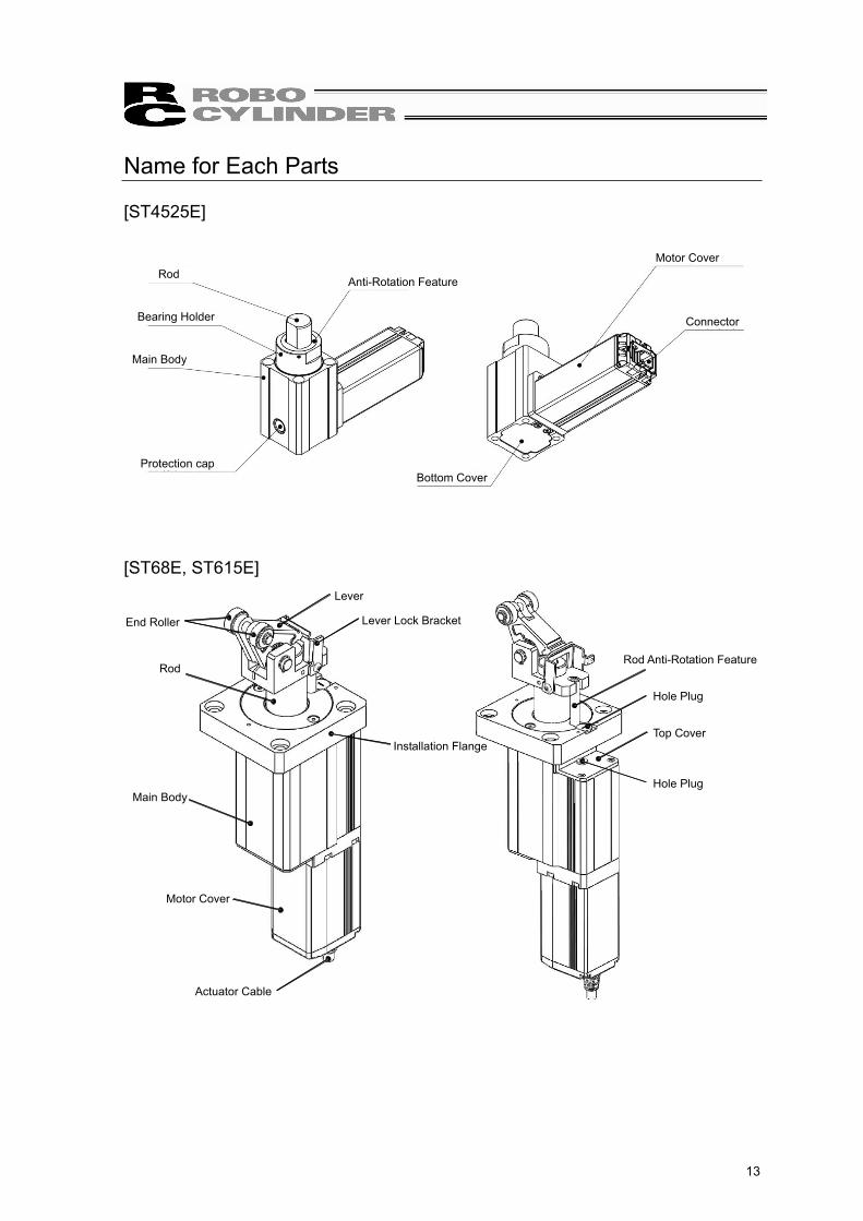
Name for Each Parts
[ST4525E]
[ST68E, ST615E]
Installation Flange
Lever
Lever Lock Bracket
Top Cover
Main Body
Actuator Cable
Motor Cover
Hole Plug
Hole Plug
End Roller
RodRod Anti-Rotation Feature
RodAnti-Rotation Feature
Motor Cover
Connector
Protection cap
Bearing Holder
Main Body
Bottom Cover

1. S
peci
ficat
ions
Che
ck
14
1. Specifications Check1.1 Product Check
1.1.1 Parts This product is comprised of the following parts if it is of standard configuration. If you find any fault in the contained model or any missing parts, contact us or our distributor. No. Part Name Model Quantity Remarks
1 Stopper Cylinder Main Body
Refer to “How to read the model plate”, “How to read the model”. 1
Accessories
CB-CA-MPACB-CA-MPA -RB
For ST68E, ST615E
shows the cable length (Example)
: 020 2 [m]2 Motor • Encoder Cables
CB-CAN-MPACB-CAN-MPA -RB
1For ST4525E
shows the cable length (Example)
: 020 2 [m]3 First Step Guide 1 4 Operation Manual (DVD) 1 5 Safety Guide 1
1.1.2 Teaching Tool A teaching tool such as PC software is necessary when performing the setup for position setting, parameter setting, etc. that can only be done on the teaching tool. Please prepare either of the following teaching tools.
No. Part Name Model
1PC Software (Includes RS232C Exchange Adapter Peripheral Communication Cable)
RCM-101-MW
2PC Software (Includes USB Exchange Adapter USB Cable Peripheral Communication Cable)
RCM-101-USB
3 Teaching Pendant (Touch Panel Teaching) CON-PTA or TB-01
4 Teaching Pendant (Touch Panel Teaching with deadman switch) CON-PDA or
TB-01D,TB-01DR
5 Teaching Pendant (Touch Panel Teaching with deadman switch TP Adapter (RCB-LB-TG)) CON-PGA
6 Teaching Pendant SEP-PT
1. Specifications C
heck
15
1.1.3 Operation Manuals Related to This Product, which are Contained in the Operation Manual (DVD).
No. Name Manual No. 1 Stopper Cylinder Operation Manual ME0292 2 MSEP Controller Operation Manual ME0299 3 ASEP/PSEP/DSEP Controller Operation Manual ME0267 4 PCON-CA/CFA Controller Operation Manual ME0289
5 PC Software RCM-101-MW/RCM-101-USB Operation Manual ME0155
6 Touch Panel Teaching CON-PTA/PDA/PGA Operation Manual ME0295 7 Touch Panel Teaching SEP-PT Operation Manual ME0217
8 Touch Panel Teaching TB-01/01D/01DR Position Control Operation Manual ME0324
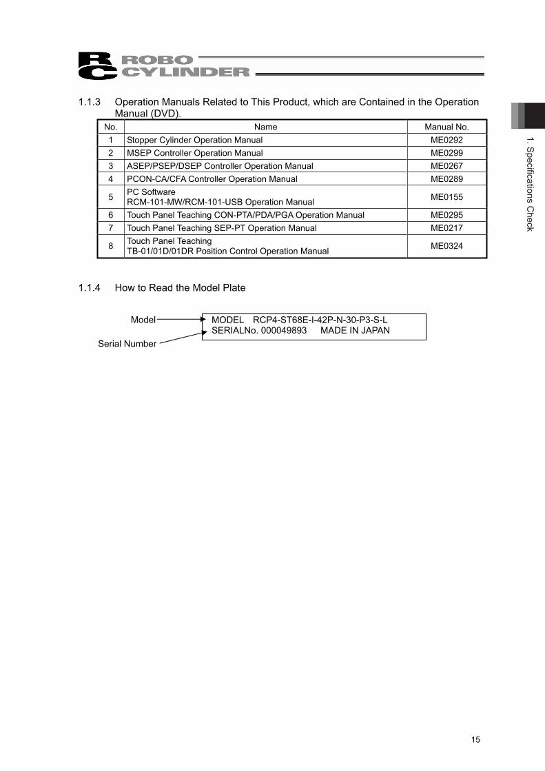
1.1.4 How to Read the Model Plate
Model
Serial Number
MODEL RCP4-ST68E-I-42P-N-30-P3-S-L SERIALNo. 000049893 MADE IN JAPAN

1. S
peci
ficat
ions
Che
ck
16
1.1.5 How to Read the Model
RCP4 – ST68E – I – 42P – N – 30 – P3 – S – L - * *
Note 1 Identification for IAI use only : It may be displayed for IAI use. It is not a code to show the model type.
Series name
<Type> ST4525E
45mm Width 25kg TypeST68E
60mm Width 80kg TypeST615E
60mm Width 150kg Type
<Encoder Type> I : Incremental
<Motor Type> 28P : 28 Size(ST4525E) 42P : 42 Size(ST68E/ST615E)
<Deceleration Ratio> N : Unspecified
Identification for IAI Use Only (Note 1)
<Option>CO : Specifications for Protection
Cover Type CJT : Difference in Cable
Orientation (Rear side) CJL : Difference in Cable
Orientation (Left side) CJR : Difference in Cable
Orientation (Right side) CJB : Difference in Cable
Orientation (Front side) NM : Reversed-home typeDCT : D-cut Shaft Tip Type (Front side)
(ST4525E) DCL : D-cut Shaft Tip Type (Left side)
(ST4525E) DCR : D-cut Shaft Tip Type (Right side)
(ST4525E) DCB : D-cut Shaft Tip Type (Rear side)
(ST4525E) AHT : Attachment Hole on Body Front
Side (Motor Opposite Side) = Tapped Hole Type
( 9 counter bored hole for standard type) (ST4525E)
<Cable Length> N : No Cable P : 1m S : 3m M : 5m X : Specified Length R : Robot Cable
<Controller> P3 : PSEP, MSEP, PCON-CA
<Stroke> 20 : 20mm (ST4525E) 30 : 30mm (ST68/ST615E)

1. Specifications C
heck
17
1.2 Specifications 1.2.1 Actuator
[1] Basic SpecificationsItem unit ST4525E
Lead mm 3 Vertical Stroke mm 20 Maximum Speed mm/sec 75 (1500rpm) Maximum Acceleration G 0.2 Cycle Time s 0.5 (0 20mm in one way, Maximum Speed, Maximum Acceleration)Rated Thrust (at maximum speed) N 9 (0.9kgf)
Repetitive Positioning Accuracy mm ±0.5
Lost Motion mm 1 Work Maximum Mass kg 25 Work Maximum Crash Speed mm/sec 333 (20m/min) Allowable Lateral Load N 25
Motor - Stepper Motor 28P Drive System Feed Screw - Lead Screw + CAM
Encoder Incremental Type 800 (It is the number of pulses input to the controller.) Mass kg 0.7
Relative Graph for Work Piece Mass - Work Piece Crash Speed
Caution : Do not set the value more than that of the maximum speed or maximum acceleration. If the product is operated exceeding any of the allowable values, it may cause a malfunction or shorter service life.
Make sure to use within the allowable range (work piece mass - work crash speed). If the product is not operated within the operation range, a large impact or vibration is given, which might cause a malfunction.
30
20
25
15
10
5
00 5 10 15 20 25
25
Operation Range
Work Piece Crash Speed [m/min]
Wor
k P
iece
Mas
s [k
g]

1. S
peci
ficat
ions
Che
ck
18
Item unit ST68E ST615ELead mm 2 Vertical Stroke mm 30 Maximum Speed mm/sec 65 (1950rpm) Maximum Acceleration G 0.2 Cycle Time s 0.6 (0 30mm in one way, Maximum Speed, Maximum Acceleration)Rated Thrust (at maximum speed) N 73.9 (7.5kgf)
Repetitive Positioning Accuracy mm ±0.5
Lost Motion mm 1 Work Maximum Mass kg 80 150 Work Maximum Crash Speed mm/sec 666 (40m/min) Allowable Lateral Load N 150
Motor - Stepper Motor 42P Drive System Feed Screw - Trapezoid Screw
Brake - Self-Lock Structure Adjustable Shock Absorber
Shock Absorber - FA-1612XBD-S-AE1 (Fuji Latex Co., Ltd.)
FA-1612XBZ-S-AE2 (Fuji Latex Co., Ltd.)
Encoder Incremental Type 800 (It is the number of pulses input to the controller.) Mass kg 3.4
Relative Graph for Work Piece Mass - Work Piece Crash Speed
Caution Do not set the value more than that of the maximum speed or maximum acceleration. If the product is operated exceeding any of the allowable values, it may cause a malfunction or shorter service life.
Make sure to use within the allowable range (work piece mass - work crash speed). If the product is not operated within the operation range, a large impact or vibration is given, which might cause a malfunction.
150 150
100
50
20
175
150
125
100
75
50
25
00 10 20 30 40 50
Wor
k P
iece
Mas
s [k
g]
Work Piece Crash Speed [m/min]
80 80
205
3
ST615E Operation Range
ST68E Operation Range

1. Specifications C
heck
19
1.3 Option
(1) Protective Cover (Model No.: CO) This protective cover protects your finger, etc. from being caught, when the rod is lowered of the model ST68E and ST615E.
(2) Difference in Cable Orientation (Model No.: CJT, CJR, CJL, CJB)If a change in the cable ejection direction is made, the direction of cable ejection will be changed of the model ST68E and ST615E.There are four types of ejection directions, rear side (model code: CJB), right side (model code: CJR), left side (model code: CJL) and front side (model code: CJT).
Front side
Left side : CJL
Right side : CJR
Rear side : CJB Front side : CJT
Protection Cover

1. S
peci
ficat
ions
Che
ck
20
(3) Reversed-home Type (Model No.: NM) The home position is set on the upper end of the rod in standard. It can be on the opposite side in case the home position is set on the other side (lower end) due to such reasons as layout of equipment.
(4) D-cut Shaft Tip Type (Front Side) (Model Code: DCT), (Left Side) (Model Code: DCL), (Right Side) (Model Code: DCR) and (Rear side) (Model Code: DCB) If the D-cut surface on the tip of the shaft of Model Code ST4525E, the direction of D-cut surface will change. There are 4 types for the direction change, front (Model Code: DCT), left (Model Code: DCL), right (Model Code: DCR) and Rear (Model Code: DCB). (Note) It is available to change the direction of D-cut surface after purchasing.
[4.5 How to Change D-cut Direction on Model Code ST4525E]
(5) Attachment Hole on Body Front Side (Motor Opposite Side) = Tapped Hole Type (Model No.: AHT)For Model Code ST425E, the attachment hole is a counter bored through hole in standard. This counter bored through hole gets replaced with a tapped hole.
Motor side
Standard [Counter Bored Type] [Tapped Type]
4- 5.5 Trough, 9 Counter Boring
Depth 74-M6, Depth 12 (Same on Other Side)
34 34
34 34
Front side : DCT
Left side : DCL
Rear side : DCB
Right side : DCR

1. Specifications C
heck
21
1.4 Motor • Encoder Cables
1.4.1 Model ST4525E
[1] Motor • Encoder Integrated Cables
CB-CAN-MPA indicates the cable length (L) (Example: 030=3m), Max.20m
Contact: DF62-2428SCFA (For AWG26) DF62-22SCFA (For AWG22)
Controller sideActuator sideConnector: DF62B-24S-2.2C
SPND-002T-C0.5 (For AWG26)SPND-001T-C0.5 (For AWG22)
Connector: PADP-24V-1-SContact:
(50) (30)
L(50)(15)
Connection diagram Actuator side Controller side
Thickness Electric Wire Color Symbol Pin No. Pin No. Symbol Electric Wire
Color Thickness
AWG22/19 Blue A 3 1 A Blue AWG22/19AWG22/19 Orange VMM 5 2 VMM Orange AWG22/19AWG22/19 Brown B 10 3 B Brown AWG22/19AWG22/19 Gray VMM 9 4 VMM Gray AWG22/19AWG22/19 Green _A 4 5 _A Green AWG22/19AWG22/19 Red _B 15 6 _B Red AWG22/19
AWG26 Black LS+ 8 7 LS+ Black AWG26 AWG26 Yellow LS- 14 8 LS- Yellow AWG26 AWG26 Blue SA 12 11 SA Blue AWG26 AWG26 Orange SB 17 12 SB Orange AWG26 AWG26 Green A+ 1 13 A+ Green AWG26 AWG26 Brown A- 6 14 A- Brown AWG26 AWG26 Gray B+ 11 15 B+ Gray AWG26 AWG26 Red B- 16 16 B- Red AWG26 AWG26 Blue BK+ 20 9 BK+ Blue AWG26 AWG26 Orange BK- 2 10 BK- Orange AWG26 AWG26 Gray VCC 21 17 VCC Gray AWG26 AWG26 Red GND 7 19 GND Red AWG26 AWG26 Brown VPS 18 18 VPS Brown AWG26 AWG26 Green LS_GND 13 20 LS_GND Green AWG26
- - - 19 22 - - AWG26 Pink - 22 21 - Pink AWG26
- - - 23 23 - - AWG26 Black FG 24 24 FG Black AWG26
(Note) About thickness AWG22/19 The thickness is AWG22 when the cable length is 5m or less, and AWG19 when longer than 5m.

1. S
peci
ficat
ions
Che
ck
22
[2] Motor • Encoder Integrated Cables Robot Type
CB-CAN-MPA -RB indicates the cable length (L) (Example: 030=3m), Max.20m
Contact: DF62-2428SCFA (For AWG26) DF62-22SCFA (For AWG22)
Controller sideActuator sideConnector: DF62B-24S-2.2C
SPND-002T-C0.5 (For AWG26)SPND-001T-C0.5 (For AWG22)
Connector: PADP-24V-1-SContact:
(50) (30)
L(50)(15)
Connection diagram Actuator side Controller side
Thickness Electric Wire Color Symbol Pin No. Pin No. Symbol Electric Wire
Color Thickness
AWG22/19 Blue A 3 1 A Blue AWG22/19AWG22/19 Orange VMM 5 2 VMM Orange AWG22/19AWG22/19 Brown B 10 3 B Brown AWG22/19AWG22/19 Gray VMM 9 4 VMM Gray AWG22/19AWG22/19 Green _A 4 5 _A Green AWG22/19AWG22/19 Red _B 15 6 _B Red AWG22/19
AWG26 Black LS+ 8 7 LS+ Black AWG26 AWG26 Yellow LS- 14 8 LS- Yellow AWG26 AWG26 Blue SA 12 11 SA Blue AWG26 AWG26 Orange SB 17 12 SB Orange AWG26 AWG26 Green A+ 1 13 A+ Green AWG26 AWG26 Brown A- 6 14 A- Brown AWG26 AWG26 Gray B+ 11 15 B+ Gray AWG26 AWG26 Red B- 16 16 B- Red AWG26 AWG26 Blue BK+ 20 9 BK+ Blue AWG26 AWG26 Orange BK- 2 10 BK- Orange AWG26 AWG26 Gray VCC 21 17 VCC Gray AWG26 AWG26 Red GND 7 19 GND Red AWG26 AWG26 Brown VPS 18 18 VPS Brown AWG26 AWG26 Green LS_GND 13 20 LS_GND Green AWG26
- - - 19 22 - - AWG26 Pink - 22 21 - Pink AWG26
- - - 23 23 - - AWG26 Black FG 24 24 FG Black AWG26
(Note) About thickness AWG22/19 The thickness is AWG22 when the cable length is 5m or less, and AWG19 when longer than 5m.

1. Specifications C
heck
23
1.4.2 Model ST68E, ST615E
[1] Motor • Encoder Integrated Cables
CB-CA-MPA indicates the cable length (L) (Example: 030=3m), Max.20m
(30) (25) (25) (15) (30)
L
Controller side
Controller side
ContactConnector : PADP-24V-1-S
SPND-002T-C0.5(AWG26)SPND-001T-C0.5(AWG22)
Actuator side
Actuator side
Contact : 1827570-2Connector : 1-1827863-1
Connection diagram
Blue(AWG22/19)Orange(AWG22/19)Green(AWG22/19)Brown(AWG22/19)Gray(AWG22/19)Red(AWG22/19)Black(AWG26)Yellow(AWG26)Blue(AWG26)Orange(AWG26)Green(AWG26)Brown(AWG26)Gray(AWG26)Red(AWG26)Blue(AWG26)Orange(AWG26)Green(AWG26)
Gray(AWG26)Red(AWG26)
Brown(AWG26)
Blue(AWG22/19)Orange(AWG22/19)Green(AWG22/19)Brown(AWG22/19)Gray(AWG22/19)Red(AWG22/19)Black(AWG26)Yellow(AWG26)Blue(AWG26)Orange(AWG26)Green(AWG26)Brown(AWG26)Gray(AWG26)Red(AWG26)Blue(AWG26)Orange(AWG26)Green(AWG26)
Gray(AWG26)Red(AWG26)
Brown(AWG26)
Black
Black
Electric wire Electric wire
-- ---
B5A5
A11B11
B10A10
A9B9
B8A8
B6A6
A7B7
B4A4
A3B3
B2A2
A1B1
Signal AbbreviationPin No. Signal
AbbreviationPin No.
232221
43
91020
191718
1312118
67
21
5
141516
24
GNDVCCVPS
LS_GNDBK-/LS-BK+/LS+
B+/Z+B-/Z-
A+/B+A-/B-
-/A--/A+
LS-/BK-LS+/BK+φ_B/-
VMM/-φB/-φ_A/WVMM/VφA/U
FG―――FG
GNDVCCVPS
LS_GNDBK-/LS-BK+/LS+
B+/Z+B-/Z-
A+/B+A-/B-
-/A--/A+
LS-/BK-LS+/BK+φ_B/-
VMM/-φB/-φ_A/WVMM/VφA/U

1. S
peci
ficat
ions
Che
ck
24
[2] Motor • Encoder Integrated Robot Cables
CB-CA-MPA -RB indicates the cable length (L) (Example: 030=3m), Max.20m
L(30) (25) (25) (15) (30)
Controller side
ContactConnector : PADP-24V-1-S
SPND-002T-C0.5(AWG26)SPND-001T-C0.5(AWG22)
Actuator side
Contact : 1827570-2Connector : 1-1827863-1
Controller sideActuator side
Connection diagram
Electric wireSignal AbbreviationPin No. Electric wireSignal
AbbreviationPin No.
B1A1
A2B2
B3A3
A4B4
B7A7
A6B6
A8B8
B9A9
A10B10
B11A11
A5B5
- -GNDVCCVPS
LS_GNDBK-/LS-BK+/LS+
B+/Z+B-/Z-
A+/B+A-/B-
-/A--/A+
LS-/BK-LS+/BK+φ_B/-VMM/-φB/-φ_A/WVMM/VφA/U
FG-
GNDVCCVPS
LS_GNDBK-/LS-BK+/LS+
B+/Z+B-/Z-
A+/B+A-/B-
-/A--/A+
LS-/BK-LS+/BK+φ_B/-VMM/-φB/-φ_A/WVMM/VφA/U
FG
Yellow(AWG25)
Red(AWG25)Green(AWG25)Brown(AWG25)Black(AWG25)Brown(AWG25)Black(AWG25)Green(AWG25)Red(AWG25)Yellow(AWG25)White(AWG25)
White(AWG25)
Gray(AWG25)Orange(AWG25)
Black(AWG22/19)White(AWG22/19)Brown(AWG22/19)Green(AWG22/19)Yellow(AWG22/19)Red(AWG22/19)
---
--
Yellow(AWG25)
Red(AWG25)Green(AWG25)Brown(AWG25)Black(AWG25)Brown(AWG25)Black(AWG25)Green(AWG25)Red(AWG25)Yellow(AWG25)White(AWG25)
White(AWG25)
Gray(AWG25)Orange(AWG25)
Black(AWG22/19)White(AWG22/19)Brown(AWG22/19)Green(AWG22/19)Yellow(AWG22/19)Red(AWG22/19)
Shield232221
43
91020
191718
1312118
67
21
5
141516
24

2. Installation
25
2. Installation
2.1 Transportation
2.1.1 Handling the Packed Unit
Unless otherwise specified, the actuator is shipped with each axis packaged separately. • Do not damage or drop. The package is not applied with any special treatment that enables it to
resist an impact caused by a drop or crash. • Keep the unit in horizontal orientation when placing it on the ground or transporting. Follow the
instruction if there is any for the packaging condition. • Do not step or sit on the package. • Do not put any load that may cause a deformation or breakage of the package.
2.1.2 Handling the Actuator After Unpacking
• Do not carry an actuator by a cable or attempt to move it by pulling the cable.
• When carrying the actuator, exercise caution not to bump it against nearby objects or structures. • Hold the body base when transporting the actuator. • Do not give any excessive force to any of the sections in the actuator.

2. In
stal
latio
n
26
2.2 Installation and Preservation Environment
This product is capable for use in the environment of pollution degree 2*1 or equivalent. *1 Pollution Degree 2: Environment that may cause non-conductive pollution or transient
conductive pollution by frost (IEC60664-1)
2.2.1 Installation Environment
The actuator should be installed in a location other than those specified below. In general, the installation environment should be one in which an operator can work without protective gear. Also provide sufficient work space required for maintenance inspection.
• Where the actuator receives radiant heat from strong heat sources such as heat treatment furnaces
• Where the ambient temperature exceeds the range of 0 to 40 C• Where the temperature changes rapidly and condensation occurs • Where the relative humidity exceeds 85% RH • Where the actuator receives direct sunlight • Where the actuator is exposed to corrosive or combustible gases • Where the ambient air contains a large amount of powder dust, salt or iron (at level exceeding
what is normally expected in an assembly plant) • Where the actuator is subject to splashed water, oil (including oil mist or cutting fluid) or chemical
solutions • Where the actuator receives impact or vibration • Place with an altitude of 2,000m or more
If the actuator is used in any of the following locations, provide sufficient shielding measures: • Where noise generates due to static electricity, etc. • Where the actuator is subject to a strong electric or magnetic field • Where the actuator is subject to ultraviolet ray or radiation
2.2.2 Storage • Preservation Environment
• The storage • preservation environment should be similar to the installation environment. In addition, make sure condensation will not occur when the actuator is to be stored or preserved for a long period of time.
• Unless specified, we do not include drying agents when shipping the actuator. If you are storing the actuator in an environment where condensation might occur, you must treat the entire shipping box, or treat the actuator itself after unpacking, to prevent condensation.
• The unit can withstand temperatures up to 60 C during a short storage • preservation period, but only up to 50 C if the storage/preservation period is longer than one month.
• The actuator should be lying flat during storage • preservation. If the actuator is to be stored in a packed state, follow the specified actuator position if indicated.

2. Installation
27
2.3 How to Install
Shown below is how to install the actuators to the machinery equipment.
2.3.1 Installation Posture
: Possible ×: Not possible
Horizontally oriented mount Vertical mount
Horizontally oriented wall
mountCeiling mount
(only for rod upward type)

2. In
stal
latio
n
28
2.3.2 Installation
[1] Model ST4525E Utilize the attachment holes provided on the frame for the attachment of the unit. There are two ways available for installation, on top and bottom, for the tapped hole type. For installation, make sure to have the distance from the bottom side of the pallet to the top side of the bearing holder 3mm or more as shown in the figures below. Distance less than 3mm may cause problems in stopping pallet or smooth control of transportation.
Follow the table below for the torque to tighten the attachment screws.Tightening Torque [N•m
Type Attachment hole
Mountingscrew In the case that aluminum is used
for the bolt seating surface:Counter Bored
5.5 through M5 3.42
Tightening Torque [N•m
Type Attachment hole
Mountingscrew
Effective Thread Depth
In the case that steel is used for the bolt seating surface:
In the case that aluminum is used for the bolt seating surface:
Tapped M6 depth 12 M6 12mm 12.34 5.36
Regarding attachment screws It is recommended to use high-tensile bolts with ISO-10.9 or more. Make sure to have the effective length of screw engagement described below or more for the tightening of a bolt and a female screw. Copper female screw: Same length as nominal length Aluminum female screw: 1.8 times more of the nominal length
Caution Pay attention when selecting screws. If a bolt other than those of the instruction is used, it may cause damage on Attachment holes or unexpected accident or failure due to insufficient strength on the actuator attachment.
Bod
y H
eigh
t IN
C T
ype:
68
AB
S T
ype:
72
3 M
in.
Bottom Surface of Pallet
Pallet
Top Surface of Bearing Holder Top Surface of Body
3434 34
4- 5.5 Trough, 9 Counter Boring
Depth 7 4-M6, Depth 12 (Same on Other Side)
[Counter Bored Type] [Tapped Type]
34

2. Installation
29
• When an operation of the rod is required without the power being turned on, the rod can be moved up and down with the procedure shown below.
[Procedure] 1) Remove the protection cap on the body.
2) Insert a hex wrench (2.5mm-sized) and twist the manual adjustment screw to move the rod up. Put the protection cap back on once the adjustment is finished.
Caution Pay attention to any foreign substance which may get into the hole when taking off the hole plugs. Make sure to put back the hole plugs after the adjustment is finished. Since the manual adjustment screw is equipped inside the body, it may cause an operation error if any foreign substance gets inside.
Protection cap
Manual Adjustment Screw (M3, Hex Socket Head Cap Screw)

2. In
stal
latio
n
30
[2] Model ST68E, ST615E Utilize the attachment holes provided on the attachment plate for the attachment of the unit.
7393106.5
527393
4-C5
4-φ9throughφ15 counterbore depth 5
Hole Plug
Follow the table below for the torque to tighten the attachment screws. Tightening torque [N•m] Attachment
holeMounting
screw In the case that aluminum is used for the bolt seating surface:
9 through M8 11.48
Regarding attachment screws It is recommended to use high-tensile bolts with ISO-10.9 or more. Make sure to have the effective length of screw engagement described below or more for the tightening of a bolt and a female screw. Copper female screw: Same length as nominal length Aluminum female screw: 1.8 times more of the nominal length
The unit can be mounted in 2 ways; one way is from the top surface of the attachment plate while the other way is from the bottom. However, make sure the dimension from the bottom surface of the pallet to the top of the attachment plate is as shown in the figure below. Not following this may cause an unsmooth control of the pallet stop or transport (Pallet overrun or pushed up)
Caution Pay attention when selecting screws. If a bolt other than those of the instruction is used, it may cause damage on Attachment holes or unexpected accident or failure due to insufficient strength on the actuator attachment.
Pallet
Bottomof Pallet
Mounting Plate Upper Surface

2. Installation
31
When an operation of the rod is required without the power being turned on, the rod can be moved up and down with the procedure shown below.
[Procedure] 1) Detach the hole plugs (2plcs) protecting the manual adjusting screw.
2) Insert a hex wrench (sized 3mm) to the hole on the installation flange, and turn the manual adjustment screw to move the rod up and down. Put the hole plugs back on once the adjustment is finished.
Caution Pay attention to any foreign substance which may get into the hole when taking off the hole plugs. Make sure to put back the hole plugs after the adjustment is finished. Since the manual adjustment screw is equipped inside the body, it may cause an operation error if any foreign substance gets inside.
Hex Wrench (sized 3mm)
Manual Adjustment Screw (M4, Hex Socket Head Cap Screw)
Hole Plug
Hole Plug

2. In
stal
latio
n
32
In such case of installing a plate as shown in the figures below, make sure to have a profile of recess on the plate to avoid blocking a hex wrench to go through. Without having the recess, moving up and down of the rod with the manual adjustment screw will be disabled. Also, remove the lower the hole plug before attaching the plate because it will be very difficult to detach after the plate is installed.
Manual Adjustment Screw (M4, Hex Socket Head Cap Screw)
Recess profilefor wrench insertion
Attachment Plate
Attachment Plate
This plug is to be removed

3. Connecting w
ith the Controller
33
3. Connecting with the Controller For the connection of the controller and actuator, use the IAI dedicated connection cable.
If the dedicated connection cable cannot be secured, reduce the load on the cable by allowing it to deflect only by the weight of the cable or wire it in a self–standing cable hose, etc., having a large radius.
Do not cut and reconnect the dedicated connection cable for extension or shorten the cable. Do not pull on the dedicated connection cable or bend it forcibly. The actuator cable coming out of the motor unit is not meant to be bent. Fix the cable so it would
not be bent repeatedly.
[Model ST4525E]
Dedicated connection cable Motor encoder cable CB-CAN-MPA ,Motor encoder robot cable CB-CAN-MPA -RB
*) indicates the cable length. Up to 20m can be specified. Example) 080 = 8m
Dedicated Connection Cable
Dedicated Controller MSEP Controller PCON-CA Controller
Robot Cable: 5 mm or less r = 68 mm or more (Movable Use): more than 5m r = 73 mm or more (Movable Use)Standard Cable: 5 mm or less r = 85 mm or more (Fixed Use): more than 5m r = 91 mm or more (Fixed Use)

3. C
onne
ctin
g w
ith th
e C
ontro
ller
34
[Model ST68E, ST615E]
Dedicated Connection Cable
MSEP ControllerPSEP ControllerPCON-CA Controller
L: 3m or moreL: 3m
r=80mm or more (Movable Use)r=68mm or more (Movable Use)
L: 3m or more L: 3m
Standard Cable
Robot Cable
r=85mm or more (Fixed Use)r=91mm or more (Fixed Use)
r
Dedicated connection cable Motor encoder cable CB-CA-MPA ,Motor encoder robot cable CB-CA-MPA -RB
*) indicates the cable length. Up to 20m can be specified. Example) 080 = 8m

3. Connecting w
ith the Controller
35
Warning : For wiring, please follow the warnings stated below. When constructing a system as the machinery equipment, pay attention to the wiring and connection of each cable so they are conducted properly. Not following them may cause not only a malfunction such as cable breakage or connection failure, or an operation error, but also electric shock or electric leakage, or may even cause a fire.
Use dedicated cables of IAI indicated in this operation manual. Contact us if you wish to have a change to the specifications of the dedicated cables.
Make sure to turn the power OFF in the process of power line or cable connection or disconnection.
Do not attempt to cut a dedicated cable with connectors on both ends to extend, shorten or re-joint it.
Hold the dedicated cable to avoid mechanical force being applied to the terminals and connectors.
Use a cable pipe or duct to have an appropriate protection when there is a possibility of mechanical damage on a dedicated cable.
In case a dedicated cable is to be used at a moving part, make sure to lay out the cable without applying any force to pull the connector or extreme bend on the cable. Do not attempt to use the cable with a bending radius below the allowable value.
Do not bend the cable in the area from the connector end inward to 150mm on both ends. Standard cable : CB-CA-MPA , CB-CAN-MPA Robot cable : CB-CA-MPA -RB, CB-CAN-MPA -RB
150mm 150mm
Make certain that the connectors are plugged properly. Insufficient connection may cause an operation error, thus it is extremely risky.
Do not lay out the cables to where the machine runs over them.
Pay attention to the cable layout so it would not hit peripherals during an operation. In case it does, have an appropriate protection such as a cable track.
When a cable is used hanging on the ceiling, prevent an environment that the cable swings with acceleration or wind velocity.
Make sure there is not too much friction inside the cable storage equipment.
Do not apply radiated heat to power line or cables.
3. C
onne
ctin
g w
ith th
e C
ontro
ller
36
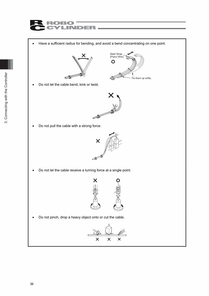
Have a sufficient radius for bending, and avoid a bend concentrating on one point.
Steel Strap(Piano Wire)
Tie them up softly.
Do not let the cable bend, kink or twist.
Do not pull the cable with a strong force.
Do not let the cable receive a turning force at a single point.
Do not pinch, drop a heavy object onto or cut the cable.

3. Connecting w
ith the Controller
37
When fixing the cable, provide a moderate slack and do not tension it too tight.
Do not use spiral tube in any position where cables are bent frequently.
Separate the I/O and communication lines from the power and drive lines. Do not wire them together in the same duct.
Power LineDuct
I/O Line(Flat Cable, etc.)
Follow the instructions below when using a cable track. If there is an indication to the cable for the space factor in a cable track, refer to the wiring
instruction given by the supplier when storing the cable in the cable track. Avoid the cables to get twined or twisted in the cable track, and also to have the cables move
freely and do not tie them up. (Avoid tension being applied when the cables are bent.) Do not pile up cables. It may cause faster abrasion of the sheaths or cable breakage.

4. M
aint
enan
ce In
spec
tion
38
4. Maintenance Inspection
4.1 Inspection Items and Schedule
Follow the maintenance inspection schedule below. It is assumed that the equipment is operating 8 hours per day. If the equipment is running continuously night and day or otherwise running at a high operating rate, inspect more often as needed.
Model ST4525E External visual
inspection
Model ST4568E,ST615E
External visual inspection
Model ST4525E Grease supply
Model ST68E, ST615EGrease supply
At startup inspection 1 month after start of operation3 month after start of operationSince then, every 3 months6 months after start operating or every 250,000 times of collision 6 months after start operating or every 1,000,000 times of collision Since then, every year or every 250,000 times of collision Since then, every year or every 1,000,000 times of collision
The greasing or oiling cycle is just only a tentative target. Adjust the oiling cycle depending on the operation condition.
4.2 External Visual Inspection
An external visual inspection should check the following things.
Main unit Loose actuator mounting bolts, other loose items Cables Scratches, proper connections Overall Irregular noise, vibration
4.3 Cleaning
• Clean exterior surfaces as necessary. • Use a soft cloth to wipe away dirt and buildup. • Do not blow too hard with compressed air as it may cause dust to get in through the gaps. • Do not use oil-based solvents as they can harm lacquered and painted surfaces. • To remove severe buildup, wipe gently with a soft cloth soaked in a neutral detergent or alcohol.

4. Maintenance Inspection
39
4.4 Grease and Oil Supply
4.4.1 Applied Grease and Oil The grease and oil listed below are applied when the product is delivered.
[Model ST4525E] Part Grease at Delivery
Bearing, Cam Operation Part Multitemp LRL No.3 Kyodo Yushi Co., Ltd. Lead Screw, Guide Shaft Sumitec 308 Sumico Lubricant Co., Ltd.
[Model ST68E, ST615E]Part Grease at Delivery
Bearing, Stopper, Absorber End Adapter, Lever Lock Multitemp LRL No.3 Kyodo Yushi Co., Ltd.
Lead Screw Sumitec 308 Sumico Lubricant Co., Ltd. Lever Pivot Machine Oil
* The grease applied on the slide screw part is poly- -olefin based synthetic grease. Even though an equivalent type of grease can be purchased from other suppliers, please be very careful in selecting grease since an inappropriate choice may give an impact to the life.

4. M
aint
enan
ce In
spec
tion
40
4.4.2 Grease and Oil Supply
[Model ST4525E]
[1] Grease Supply to Slide Screw
1) Remove the two cross recessed flat-head screws (M2.6 × 6) with the rod being moved to the upper end to detach the bottom cover.
2) Supply moderate amount of grease on the slide screw that can be seen inside. To spread the grease on the screw evenly, move the rod up and down by turning the manual adjustment screw with the hex wrench while supplying grease.For how to use the manual adjustment screw, refer to “2.3.2 Installation”
3) Put all the detached parts back and the grease supply is complete.
BottomCover
Cross Recessed Flat-Head Screw (M2.6 × 6)
Sumitec 308

4. Maintenance Inspection
41
[2] Grease Supply to Bearing 1) With the rod moved to the upper end, remove the M3 × 4 hex socket set screws
(recessed ended) to detach the anti-rotation ring.2) Bearing appears once the anti-rotation ring is removed. Supply grease on it.
To supply grease inside the bearing, twist the manual adjustment screw with the hex wrench to move the rod up and down while supplying grease.For how to use the manual adjustment screw, refer to “2.3.2 Installation”
3) Put all the detached parts back and the grease supply is complete. Apply thread-locking fluid on the M3 × 4 hex socket set screws before tightening. Screw Torque : 69N•cm(Note) Pay attention to the orientation of the anti-rotation ring.
Anti-Rotation Ring
Hex Socket Set Screw (Recessed Ended M3×4)
Multitemp LRL No.3

4. M
aint
enan
ce In
spec
tion
42
[Model ST68E, ST615E]
[1] Oil Supply on Lever • Apply grease on the adapter on the end of the absorber, lever locking and lever releasing
features. • Apply machine oil on the lever pivoting and sliding sections.
Have regular inspections and supply oil when necessary.
Multitemp LRL No.3
Machine Oil
Machine Oil
Multitemp LRL No.3
[2] Oil Supply to Bearing 1) Detach the protection cover for the type equipped with the protection cover (option).
Move the rod to the upper end to remove the hex socket head flat cap screws M4 x 8 and moved upward the scraper.
2) When the scraper is moved upward, the bearing section appears. Apply grease on the section.
3) Push in the scraper. 4) Put all the removed parts back and the work is complete.
Multitemp LRL No.3
Scraper
M4 × 8 Hex Socket Head Flat Cap Screw
Sealing Plate

4. Maintenance Inspection
43
[3] Grease Supply to Trapezoid Screw Thread 1) Remove two M3 x 8 cross recessed flat-head screws with the rod being moved to the
upper end to detach the under plate. 2) Apply grease to the slide screw that can be seen inside. To spread the grease to the
whole area, move the rod up and down by turning the manual adjustment screw with a hex wrench while applying the grease. For how to use the manual adjustment screw, refer to “2.3.2 Installation”
3) Put all the removed parts back and the work is complete.
M3 × 8 Cross Recessed Flat-head Screws
Under Plate
Sumitec 308

4. M
aint
enan
ce In
spec
tion
44
4.4.3 How to Replace Maintenance (Consumable) Parts
The component that requires maintenance (consumable part) is the shock absorber. The number of crash operation before replacement that is recommended by the supplier of the shock absorber is 1,000,000 times (reference). There is a possibility that the drag drops down by 20% from the initial performance after 1,000,000 times of crash. Therefore, it may require a re-adjustment of drag of the shock absorber from the initial setting or replacement of the shock absorber in some cases. (Note) It does not mean that the shock absorber will break straight after 1,000,000 times of
crash.
[1] How to Adjust Shock Absorber Drag
Open the lever
Open the lever bracket
Pull out the shock absorber
[Small drag] 1 < 2 < 3 [Large drag]
Hold on the knurled area to pull upwards
Move the robot to upper end
After absorber drag adjusted,tighten up the locking screwand put it in the body.
Lockingscrew

4. Maintenance Inspection
45
[Adjustment of Min. Drag of Absorber to Work Piece (Object to Collide)]
Regarding how to adjust the drag of the absorber to the work piece, determine by confirming the behavior of the lever when the actual work piece is collided. The detent structure by the locking bracket works on the lever (to get to locked condition) when the drag of the absorber to the collision force of the work piece is optimum. The drag of the absorber is too high when the lock does not work. On the other hand, when the drag of the absorber is too low, the crash noise gets loud and the work piece could bounce. Even though the locking structure works, the collision force to the lever and absorber units is large, and it may give a bad influence to the body. The drag that makes the locking structure work and makes the collision force on the lever and absorber unit minimum is defined as the optimum. (Although there is no problem to the collision of the lever and absorber unit, it may give a bad influence to the body when the collision force is high.)
<Before work piece collision>
Work
Although locking structure works, collision force to lever and absorber unit are high
<Absorber drag = Low>
WorkLocking structure does not work
<Absorber drag = High>
Work
Locking structure works Collision force on lever and absorber unit low
<Absorber drag = Optimum>

4. M
aint
enan
ce In
spec
tion
46
[2] How to Replace Shock Absorber
Eccentric Angle Adapter Between 2 Flat Faces: 19mm
Shock Absorber Between 2 Flat Faces: 19mm
Adapter Pin Affix the eccentric angle adapter to the shock absorber with an M16 nut at the point where the adapter pin hits the very end of the shock absorber. At this time, push the adapter pin to confirm that it moves with no play to the pin.
Shock Absorber: • ST68E : FWM-1612XBD-S-AE1
(Fuji Latex Co., Ltd.) • ST615E: FA-1612XBZ-S-AE2
(Fuji Latex Co., Ltd.)

4. Maintenance Inspection
47
4.5 How to Change D-cut Direction on Model Code ST4525E 1) Remove the M3 × 4 hex socket set screws (recessed ended) to detach the anti-rotation
ring.2) Once the anti-rotation ring is removed, the rod can change the direction.
Change the direction of the D-cut surface.For cautions regarding angle of interfacing of D-cut surface and pallet, refer to 2 in [Precautions in Operation]
3) Put all the detached parts back and the D-cut surface direction change is complete.Apply thread-locking fluid on the M3 × 4 hex socket set screws before tightening. Screw Torque : 69N•cm(Note) Pay attention to the orientation of the anti-rotation ring.
Anti-Rotation Ring
Right side : DCR
Rear side : DCB
Left side : DCL
Front side : DCT
Hex Socket Set Screw (Recessed Ended M3×4)

5. L
ife o
f the
Sho
ck A
bsor
ber
48
5. Life of the Shock Absorber This shall be 1,000,000 times (reference) of collision assuming it is operated with maximum work piece mass, maximum acceleration and deceleration.

6. External D
imensions
49
6. External Dimensions
6.1 RCP4-ST4525E
6.1.1 Counter Bored Type (Standard)
[M.E] Mechanical End * The upper end of the rod is the home position if the home position is in standard.
The lower end of the rod is the home position if the home position is reversed.
Mass 0.7kg
8
1(M
.E)
1(M
.E)
98 6 45149
6820
40
φ 36
Stro
ke =
20
(108
)
φ 20
2018
384045
132
42
17
(φ20)
Manual Adjustment ScrewProtection cap
34
34
45
45
φ 60
Manual Adjustment Screw(Hex Socket, 2.5mm-sized)
Left side : DCL
Rear side :DCB
Right side : DCR
Front side :DCT
Direction of D-cut Surface
4-φ5.5 Trough, φ9 Counter BoringDepth 7

6. E
xter
nal D
imen
sion
s
50
6.1.2 Tapped Type (Option : Model AHT)
[M.E] Mechanical End * The upper end of the rod is the home position if the home position is in standard.
The lower end of the rod is the home position if the home position is reversed.
Mass 0.7kg
17
(φ20)
Manual Adjustment ScrewProtection cap
8
1(M
.E)
1(M
.E)
6 4598149
6820
40(1
08)
φ 36
Stro
ke =
20
φ 20
2018
321
42
3840
(45)
Manual Adjustment Screw(Hex Socket, 2.5mm-sized)
34
34
4-M6 Depth 12Same on other side
φ 60 45
45
X
X Sectional view X-X(M6 Depth 12)(M6 Depth 12)
Left side : DCL
Rear side :DCB
Right side : DCR
Front side :DCT
Direction of D-cut Surface

6. External D
imensions
51
6.2 RCP4-ST68E, ST615E
ST68E 3.4kgMassST615E 3.4kg
[M.E]: Mechanical end*When the home position in normal, the home position is in the rod upper directionWhen the home position in opposite, the home position is in the rod lower direction
R40
24° 15.85
2(M
.E)
Stro
ke=3
02
(M.E
)15
.55.
512
8
20
115.
5
12.5
105.
5
221
20
21
60
17(1
4.8)
ConveyorLower End
Conveyor Upper End(Roller Center Point)
HolePlug
View T
View U
883645
φ20
(28.5) (22.7)
60
52
47
7393106.5
527393
4-C5
4- φ9 Throughφ15 Counterbore Depth 5Drawing View: View T
Hole Plug
38(From Center)
φ11.5
Manual Adjustment Screw
(Hex Wrench sized 3mm)
60 52
60
16.533.5 56.5
90
Drawing View: View U
Manual Adjustment Screw

6. E
xter
nal D
imen
sion
s
52
Protection Cover Type
(20)
4533
76
(93)
(93)(106.5)
(52)
(68)
68
15
16
(45)

7. Warranty
53
7. Warranty
7.1 Warranty Period One of the following periods, whichever is shorter: 18 months after shipment from our company 12 months after delivery to the specified location 2,500 operational hours
7.2 Scope of the Warranty Our products are covered by warranty when all of the following conditions are met. Faulty products covered by warranty will be replaced or repaired free of charge:
(1) The breakdown or problem in question pertains to our product as delivered by us or our authorized dealer.
(2) The breakdown or problem in question occurred during the warranty period.
(3) The breakdown or problem in question occurred while the product was in use for an appropriate purpose under the conditions and environment of use specified in the operation manual and catalog.
(4) The breakdown or problem in question was caused by a specification defect or problem, or by the poor quality of our product.
Note that breakdowns due to any of the following reasons are excluded from the scope of warranty: [1] Anything other than our product [2] Modification or repair performed by a party other than us (unless we have approved such
modification or repair) [3] Anything that could not be easily predicted with the level of science and technology
available at the time of shipment from our company [4] A natural disaster, man-made disaster, incident or accident for which we are not liable [5] Natural fading of paint or other symptoms of aging [6] Wear, depletion or other expected result of use [7] Operation noise, vibration or other subjective sensation not affecting function or
maintenance
Note that the warranty only covers our product as delivered and that any secondary loss arising from a breakdown of our product is excluded from the scope of warranty.
7.3 Honoring the Warranty As a rule, the product must be brought to us for repair under warranty.
7.4 Limited Liability (1) We shall assume no liability for any special damage, consequential loss or passive loss such as
a loss of expected profit arising from or in connection with our product. (2) We shall not be liable for any program or control method created by the customer to operate our
product or for the result of such program or control method.

7. W
arra
nty
54
7.5 Conditions of Conformance with Applicable Standards/Regulations, Etc., and Applications
(1) If our product is combined with another product or any system, device, etc., used by the customer, the customer must first check the applicable standards, regulations and/or rules. The customer is also responsible for confirming that such combination with our product conforms to the applicable standards, etc. In such a case we will not be liable for the conformance of our product with the applicable standards, etc.
(2) Our product is for general industrial use. It is not intended or designed for the applications specified below, which require a high level of safety. Accordingly, as a rule our product cannot be used in these applications. Contact us if you must use our product for any of these applications:
[1] Medical equipment pertaining to maintenance or management of human life or health [2] A mechanism or mechanical equipment intended to move or transport people (such as a
vehicle, railway facility or aviation facility) [3] Important safety parts of mechanical equipment (such as safety devices) [4] Equipment used to handle cultural assets, art or other irreplaceable items
(3) Contact us at the earliest opportunity if our product is to be used in any condition or environment that differs from what is specified in the catalog or operation manual.
7.6 Other Items Excluded from Warranty
The price of the product delivered to you does not include expenses associated with programming, the dispatch of engineers, etc. Accordingly, a separate fee will be charged in the following cases even during the warranty period:
[1] Guidance for installation/adjustment and witnessing of test operation [2] Maintenance and inspection [3] Technical guidance and education on operating/wiring methods, etc. [4] Technical guidance and education on programming and other items related to programs

Change H
istory
55
Change History
Revision Date Revision Description 2012.11
2012.12
2013.12
2014.12
First Edition
Second Edition Pg. 18 Model names changed. PSEP deletes it for the not corresponding.
Third Edition ST68E and ST615E specification are added. 70kg specification deleted.
Fourth Edition ST4525 added


Manual No.: ME0292-4A (December 2014)
The information contained in this document is subject to change without notice for purposes of product improvement.Copyright © 2014. Dec. IAI Corporation. All rights reserved.
14.12.000
Head Office: 577-1 Obane Shimizu-KU Shizuoka City Shizuoka 424-0103, JapanTEL +81-54-364-5105 FAX +81-54-364-2589
website: www.iai-robot.co.jp/
Ober der Röth 4, D-65824 Schwalbach am Taunus, GermanyTEL 06196-88950 FAX 06196-889524
SHANGHAI JIAHUA BUSINESS CENTER A8-303, 808, Hongqiao Rd. Shanghai 200030, ChinaTEL 021-6448-4753 FAX 021-6448-3992
website: www.iai-robot.com
Technical Support available in USA, Europe and China
Head Office: 2690 W. 237th Street, Torrance, CA 90505TEL (310) 891-6015 FAX (310) 891-0815
Chicago Office: 110 East State Parkway, Schaumburg, IL 60173TEL (847) 908-1400 FAX (847) 908-1399
TEL (678) 354-9470 FAX (678) 354-9471website: www.intelligentactuator.com
Atlanta Office: 1220 Kennestone Circle, Suite 108, Marietta, GA 30066
825, PhairojKijja Tower 12th Floor, Bangna-Trad RD., Bangna, Bangna, Bangkok 10260, ThailandTEL +66-2-361-4458 FAX +66-2-361-4456