RCI-1502 LM Telescopic Boom System - Squarespace LM Telescopic Boom System Instruction Manual...
95
RCI-1502 LM Telescopic Boom System Instruction Manual MAN-1074 Rev G LSI-Robway Pty Limited, 32 West Thebarton Road, Thebarton, South Australia, 5031 Phone: +61 (0) 8 8238 3500 Fax: +61 (0) 8 8352 1684 www.lsirobway.com.au
Transcript of RCI-1502 LM Telescopic Boom System - Squarespace LM Telescopic Boom System Instruction Manual...

RCI-1502 LM Telescopic Boom SystemInstruction Manual
MAN-1074 Rev G
LSI-Robway Pty Limited, 32 West Thebarton Road, Thebarton, South Australia, 5031Phone: +61 (0) 8 8238 3500 Fax: +61 (0) 8 8352 1684 www.lsirobway.com.au


Contents Page No.
1. Important Safety Notice ................................................................................... 3
2. General Description ......................................................................................... 4
3. Operating Instructions..................................................................................... 5 3.1. Turning On the RCI-1502................................................................... 5 3.2. Turning Off the RCI-1502 .................................................................. 5 3.3. Operating Screen............................................................................... 6 3.4. Display Functions.............................................................................. 7 3.5. Data Logging and Data Downloading .............................................. 9
4. Installation ........................................................................................................ 10
5. Calibration......................................................................................................... 17 5.1. Verifying Operation of Sensors........................................................ 20 5.2. Configuring User Variables .............................................................. 21 5.3. Calibrating Main Boom Angle........................................................... 28
5.3.1. Calibrating Low Boom Angle ............................................. 28 5.3.2. Calibrating High Boom Angle ............................................ 28
5.4. Calibrating Main Boom Length......................................................... 29
5.4.1. Calibrating Short Boom Length......................................... 29 5.4.2. Calibrating Long Boom Length ......................................... 29
5.5. Calibrating Low End & High End of Transducers........................... 30
5.5.1. Calibrating the Low End of Transducer 1 (Bore Side)..... 30 5.5.2. Calibrating the High End of Transducer 1 (Bore Side) .... 30 5.5.3. Calibrating the Low End of Transducer 2 (Rod Side) ...... 31 5.5.4. Calibrating the High End of Transducer 2 (Rod Side) ..... 31
5.6. Calibrating Load for Active Winch .................................................. 32
5.6.1. Calibrating a Duty ............................................................... 32 5.6.2. Calibrating a Boom Section ............................................... 33 5.6.3. Examples on Section Number Selection .......................... 34
5.7. Copying and Restoring Calibration Data Function ........................ 36
6. Troubleshooting............................................................................................... 42
7. Electrical Specifications.................................................................................. 48
8. Appendices....................................................................................................... 51

1. Important Safety Notice The RCI-1502 System is a crane device which warns the operator of impending overload conditions and of overhoist conditions which could cause damage to property, crane and personnel. The system is not a substitute for good operator judgement, experience and safe crane operation. The operator is solely responsible for the safe operation of the crane. The operator must, prior to operation of the crane, read this manual carefully and thoroughly and shall ensure that all operational instructions and warnings are understood and complied with. Proper system operation requires the operator to correctly program the RCI System to match the crane setup and working configuration. The system is equipped with an override key which bypasses alarms and motion cut function at which time the system can no longer warn of impending overload and must only be operated strictly in accordance to the crane manufacturer’s setup and operation procedures. Operation of this key is for authorised personnel only who shall be solely responsible for its use.

2. General Description
This Manual contains general information, installation, operation, calibration,
maintenance and parts information for the RCI-1502 Rated Capacity Indicator to suit various Telescopic boom mobile cranes.
Refer to drawing DWG 3063 “RCI-1502 GENERAL ARRANGEMENT FOR TYPICAL TELESCOPIC BOOM LM SYSTEM” on Section 8.2. of the Manual for an overview of
the System.
Drawing (DWG) Numbers, where applicable in the following Sections, are also provided for quick reference.
The RCI-1502 is a fully automatic Rated Capacity Indicator which provides a display of the following functions:
Boom Length, Boom Angle, Hook Radius, S.W.L. (Safe Working Load), Hoist Rope Falls, Duty (Configuration), Actual Load of Selected Winch (Main or Aux), Percentage of SWL (3 coloured lamps - green, amber, and red).
The RCI-1502 display also provides the following features:
Visual and audible alarms on warning (approach to overload),
overload, motion-cut, two-blocking detection, and error detection, Self-diagnosis and error codes, Data-logging, Built-in calibration and fault-finding tools, Units conversion (imperial/metric) facility, Anti-two-block (overhoist limit) facility.

3. Operating Instructions The following sections explain how to operate the RCI-1502 and make best use of its
capabilities. 3.1. Turning On the RCI-1502
Power to the unit is from the crane battery (nominal 12 or 24 volts dc) through the start-up or ignition key. In some applications an additional switch may be used to enable the operator to switch the unit on/off as required. As soon as power is applied to the unit, its display and other indicators should light up and the unit should go through its self-test operation.
3.2. Turning OFF the Unit The unit will stop working as soon as the power is removed from it by switching off any of the switches indicated in Section 3.1 above.
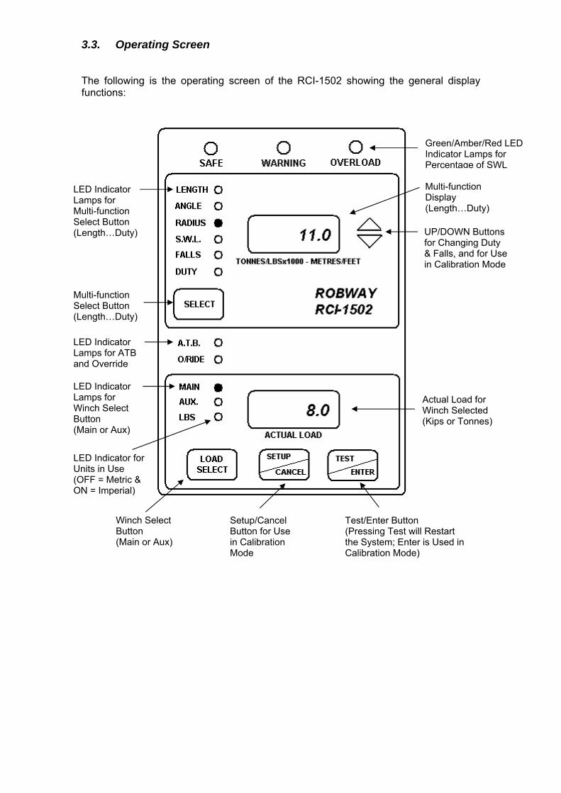
3.3. Operating Screen The following is the operating screen of the RCI-1502 showing the general display functions:
Multi-function Select Button (Length…Duty)
Multi-function Display (Length…Duty)
Green/Amber/Red LED Indicator Lamps for Percentage of SWL
LED Indicator Lamps for Multi-function Select Button (Length…Duty)
Actual Load for Winch Selected (Kips or Tonnes)
LED Indicator Lamps for ATB and Override LED Indicator Lamps for Winch Select Button (Main or Aux)
Setup/Cancel Button for Use in Calibration Mode
Winch Select Button (Main or Aux)
Test/Enter Button (Pressing Test will Restart the System; Enter is Used in Calibration Mode)
UP/DOWN Buttons for Changing Duty & Falls, and for Use in Calibration Mode
LED Indicator for Units in Use (OFF = Metric & ON = Imperial)

3.4. Display Functions
The RCI-1502 has 2 LCD display windows and 6 front panel push buttons. The display panel can also be grouped into four parts as follows:
3.4.1. “Approach to Rated Capacity” Indication Lamps
This is the uppermost part of the display which contains three coloured lamps to indicate “approach to rated capacity”. Factory settings are as follows:
Green: 50 to 84%, Amber: 85 to 99%, Red: 100 to 110% Amber lamp flashes when first trip point is reached (i.e. 85%
Rated Capacity) plus an intermittent audible alarm. Red lamp will flash at 100% of rated capacity plus a continuous
audible alarm. Red lamp will stop flashing and will stay ON when the lifted load
exceeds 110% of SWL plus a continuous audible alarm. Crane motion controls are also activated at this stage if fitted.
3.4.2. Numerical LCD for Various Functions
This is a numerical LCD display, just below the indication lamps mentioned above, which shows the LENGTH, ANGLE, RADIUS, S.W.L., FALLS, and DUTY status.
This window is also used to display ERROR codes when any errors are detected. The error function cannot be manually selected but will be displayed automatically if there are any errors. Please refer to Section 6. “Troubleshooting” for the meaning and description of the error codes.
The above functions are selected by pressing the SELECT button on the front panel. The selected function is indicated by the lamp next to the labels. The display functions are as follows:
LENGTH
The numerical display shows the BOOM length, in unit selected (feet or metres), for the winch selected. ANGLE
The numerical display shows the current working angle in degrees which is read from the main boom angle sensor.
RADIUS
The numerical display shows the current working radius, in unit selected (feet or metres), for the winch selected. SWL
The numerical display shows the current maximum safe working load in unit selected (kilopounds or tonnes). The S.W.L. will depend on the current crane configuration (duty), winch selected (if twin winch), the maximum linepull and the falls selected.

FALLS The numerical display shows the number of falls (parts of line) used for the winch selected. To change the falls, press the UP/DOWN arrow keys to ramp to the desired falls number while the FALLS indicator is on, make sure the correct winch is selected. DUTY
The numerical display shows the current duty (or configuration) number selected. Each system manual is supplied with a DUTY LISTING for a given application. Please refer to the DUTY LISTING at the rear of the manual for a description of the duties. A plastic encapsulated version is also supplied with the system for the crane operator’s quick reference in the cabin. To change the Duty number, use the UP/DOWN key to ramp to the desired value, while the DUTY LED indicator is on.
3.4.3. A.T.B. (Anti-Two-Block) and O/RIDE (Override) Indication LEDs
This part of the display has two red LED’s which shows the current status of the following functions:
O/RIDE - LED ON when over-ride/bypass key is switched on.
A.T.B. - LED ON when on two-blocking condition.
The RCI-1502 is supplied with a standard Anti-Two-Block (ATB) input for connecting an optional ATB sensor to prevent two-blocking. When the ATB indicator on the front panel is lit, a two-blocking condition has occurred and further hoisting is stopped by activating the motion cut relay, if installed.
3.4.4. Numerical LCD for Current Load Readout
This part has a numerical LCD which shows the current load, in unit selected (kilopounds or metric tonnes), on the winch selected.
There are three red LED’s on the left side of this window. The MAIN and AUX LED’s indicate which winch is selected. The LBS LED indicates the units selected. LED ON means Imperial Units (kips, feet) and LED OFF means Metric Units (tonnes, metres).
Use the WINCH SELECT button to switch between MAIN and AUX winches. For Single Winch cranes, only the MAIN winch is active and the AUX LED is disabled. Although the RCI-1502 will always check safe operation for both winches, you should make sure that the correct winch is selected as the winch selection affects the values shown on the displays.
When the ACTUAL LOAD exceeds the SWL for the current crane configuration the RCI-1502 will activate audible and visual alarms.

If the overload is higher than the SWL % for MOTION CUT OUTPUT, set in calibration mode, the instrument will also activate the motion cut relay, if installed. This will then stop further over-loading of the crane. To bypass or temporarily disable motion cut, the operator must use the over-ride key which should be held by the site-supervisor. When the key is inserted into the display and is turned on the O/RIDE indicator is illuminated as a reminder.
ROBWAY recommends that the over-ride key be switched OFF at all times and the over-ride key be held by the site-supervisor.
3.5 Data Logging and Data Downloading
For downloading data to PC, connect the Data-Logging Download Cable (Part No. CABCOM 1261) between the RS-232 socket at the back of the RCI-1502 display and the PC.
Please refer to Section 8.1. “DATA LOGGING ON RCI SYSTEMS” at the rear of the manual for usage information and details.

4. Installation
SETTING UP THE CRANE
Lower the crane boom to a safe and convenient position.
INSTALLING BOOM PARTS
Recoil Drum
The recoil drum contains both the angle sensor and length sensor for telescopic cranes. The payout cable of the drum is also used for wiring the ATB switch/es if required. It is supplied for right hand side mounting unless ordered specifically for left hand side mounting.
The recoil drum comes complete with mounting bolts, payout wire roller guides and boom tip tie-off bracket.
First remove the recoil drum cover and set aside. Fix the recoil drum and payout cable to the right hand side of the main boom by welding the mounting bolts provided to a suitable location on the side of the boom. Mount the recoil drum on the bolts ensuring that the electrical connection socket is pointing towards the cabin. Ensure the recoil drum is mounted 'squarely' to the boom side panel, this is essential to avoid incorrect payout wire spooling problems.
When the recoil drum is mounted to the left hand side of the boom, the electronic angle sensor must also be adjusted to get it working to its full range. Please refer to drawings DWG 1199, 1239, & 2159 at the rear of this manual for the correct position of the angle sensor.
Select a convenient uninterrupted payout cable alignment along the side of the boom and cut and weld the anchor post provided to a suitable position on the boom head, so that the cable can be clamped into the groove on the post to obtain a temporary line. Select positions for the intermediate cable roller guides provided, one for each telescoping section and one or more for the main boom allowing 3-4m between the drum and the nearest cable roller guide. Measure the distance from the cable to the sides of the boom sections, record lengths and mark the positions for the roller guides. Cut and weld the brackets of the guides to the sides of the boom sections after removing the cable. Refit the cable through the guides and then anchor it to the post using the clamp provided.
When the installation is complete, the recoil spring should be 'maximised' to ensure that maximum available tension is applied to the payout wire to prevent poor spooling onto the recoil drum. If possible, extend the boom fully at zero degrees and pull the recoil drum payout wire fully out by hand until the spring 'locks up'. Allow 2 metres of payout wire to return back onto the drum and cut off the excess. Remake the connection to the boom tip tie-off bracket. Remember to leave sufficient cable length for connection to the anti-2-block switch if one is being fitted.
If it is not possible to safely extend the boom at zero degrees, then simulate by extending the payout by hand to a mark on the ground representing the full telescopic extension.

Fully retract the boom. Extend the payout wire slightly and note the direction of rotation of the large gear wheel for an extending boom. Release the payout wire and allow it to retract to its' fully retracted position. Turn the large aluminium gear, by hand, in the opposite direction to that noted for an extending boom, until the gear stops. Turn the gear in the opposite direction (i.e. as if for extending) for ¾ of a turn or three clicks of the clutch. Safely extend the boom to full extension ensuring continuous operation of the gear wheel and potentiometer. Fully retract the boom and again check operation. Refit the recoil drum cover and ensure all mounting nuts are tight.
Route the cable carefully from the recoil drum back around the boom pivot to the cabin. Fix the cable to the boom and turret using adequate fixings ensuring that the cable is not pinched or stretched as the boom moves through its full luffing arc. Only connect the cable to the Display Unit when finished welding.
Notes: The slip-rings in the ROBWAY recoil drum are designed for use with ROBWAY Anti-2-block systems and are not for resistive or inductive circuits such as lights or bells. If you have a particular application that you feel may be applicable to the slip-ring facility, please contact ROBWAY for further advice.
Please note also that high tensile booms require proper welding procedure specifications. Obtain specialist assistance in these cases.
Pressure Transducers
The RCI-1502 System uses two pressure transducers fitted to the hydraulic luff cylinder/s, one into the bore (force) side and one into the rod (annular) side of the cylinder to monitor the total forward moment force of the boom for load sensing.

Bore (Force) Side Transducer
The bore or force side transducer, also known as piston side transducer, must be fitted to the full bore side of the luff cylinder from which “live” pressure is measured. If a lock valve is fitted to the bore side, the transducer must be fitted to the “live” side of the valve.
The bore pressure transducer can also be installed into the hydraulic line such as a high pressure pipe or hose feeding the BOTTOM of the luff cylinder. Ensure it is fitted to DIRECTLY read the internal pressure WITHOUT being influenced by outside check valves or similar.
For cranes with two luff cylinders, the two bore sides must be equalised by a high pressure equalising pipe or balance pipe, and only one bore transducer is required to be fitted into this equaliser to measure the “live” pressure from the two luff cylinders.
Rod (Annular) Side Transducer
The rod or annular side pressure transducer can be installed into the hydraulic line such as a high pressure pipe or hose feeding the TOP of the luff cylinder. Ensure it is fitted to DIRECTLY read the internal pressure WITHOUT being influenced by outside check valves or similar.
For cranes with two luff cylinders, the rod side need not be equalised as the bore side, i.e. only one rod transducer is required to be fitted into any one of the two luff cylinders.
Drawing Reference: DWG 1810 – “Pressure Tranducer (5000/10000 PSI) Dimensional Detail”
Typical installation of pressure transducers on the bore (force) side and rod (annular) side of the hydraulic luff cylinder/s
Anti-Two-Block (Optional Item)
Fix the anti-two-block (ATB) switch mounting bolt by welding it to the boom head preferably so that the bob weight (when suspended from the switch) can be fitted to the static hoist rope below the rope anchor. Check that the switch works correctly as the boom luffs throughout its working range.
Bore or Force Side Transducer
Rod Side Transducer

Additional switches (for fly-jibs) can be added. Connection is via the bullet-type connectors from the cable. When more than one ATB switch is required (e.g. main & fly), connect the ATB cables of the switches in series via the bullet-type connectors.
Hang the bob weight assembly from the switch eye after cutting the chain to length if desired to suit winch line speed. Repeat the procedure if required for rooster or fly jib.
Drawing References: DWG 2934 – “Dimensional Detail, BB5 Anti-Two-Block Switch” DWG 0667 (Sheets 1-2 of 3) – “ATB Switch Installation Details, Telescopic
Crane”
Please note that high tensile booms require proper welding procedure specifications. Obtain specialist assistance in these cases.
Model BB-5 anti-two-block (ATB) switch
Cabling (Boom Sensors)
Sensor cables should be fixed firmly to where they are installed and routed along the boom chords through to the crane cabin ensuring freedom of movement around the boom pivot pin.
The cables are normally quite robust. They should be treated with care, however, as even a small amount of damage can be very costly due to down-time or intermittent behaviour. Always support the cable in such a way that there is no "excessive" strain applied, such as tension or flexing. The cable should be strapped to a fixed member that it runs along, unless it is held within a cable tray or trunking. Clip cables at approximately 60mm intervals or where suitable to secure them firmly to the boom. Avoid sharp bends such as around a sharp corner. Where there is to be flexing, the installer must ensure that the bending is reduced to an absolute minimum to avoid fatigue breakage of the conductors.
Drawing Reference: DWG 1224 – “RCI Series Cable Connections”

Connectors
It is recommended that the installer applies a suitable silicone grease (e.g., Dow Corning 4 “Electrical Insulating Compound” or any similar compound) on the plugs and sockets prior to connecting the cables. The silicone grease should be smeared across the connector contact points to increase the water proofing of the connector.
INSTALLING CABIN PARTS
Display Unit and Key Switch Box
Fit the RCI-1502 Display Unit and Key Switch Box in a convenient position in the crane cabin such that the operator can view the displays and reach the push buttons comfortably.
Connect the Switch Box power supply lead to the key start switch or directly to the battery via a relay that is energised by the key start switch. Ensure that the polarity of the power supply is correctly connected.
Standard back plate bracket and kit comprising of bolts and nuts are provided. Special bracket may need to be fabricated on site for suitable mounting in the cabin.
Connect the load, angle, and anti-two-block ATB cables to the display unit.
Note: If a good earth connection between the mounting bracket and the cabin cannot be guaranteed then the earthing wire attached to the base of the display must be used to properly earth the display. Failure to do so could result in a non-operational ATB signal and faults due to Radio Frequency Interference.
Drawing References: DWG 0279 – “Dimensional Drawing, RCI-1502 Display” DWG 2459 – “Dimensional Detail, RCI-1502 Switchbox” DWG 3336 – “RCI-1502 Switchbox V2 Wiring Diagram”
Display unit and typical installation inside the cabin

WIRING SLEW SWITCH/ES AND MOTION CUT OUTPUT
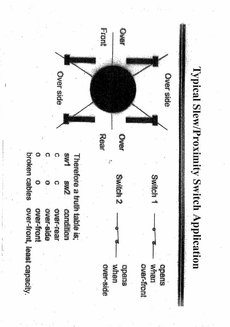
Slew/Proximity Switch/es (Optional Items)
The slew switch is used when the crane has different zones of SWL (e.g. over-rear ratings, over-side ratings, etc.). The switch will convey a signal to the display when the crane moves into a zone of different capacity rating. The RCI-1502 system can interface with up to three switches maximum.
The switch is magnetically switched and requires a metal target to switch ON. Fabricate, fix and secure a suitable mounting plate to the switch between the two locknuts supplied. Mount the plate/switch assembly at a suitable location on the revolving upperstructure preferably so that the switch moves and rotates with the upperstructure. The metal target plate must be mounted at a safe and suitable location on the carrier about which the upperstructure rotates.
Alternatively, fix the switch and target plate around the centre post of the crane slew (refer to typical installation photo below).
The gap between the switch and target must not exceed 10mm. The switch distance can be adjusted via the locknuts.
Connect the switch to the RCI-1502 Switchbox as per DWG 3336 (refer to Section 8.2. “Drawings” for details).
Drawing References: DWG 2461 – “Dimensional Details, Proximity Switch (SWIPROX02)” DWG 2462 – “Dimensional Details, Proximity Switch (SWIPROX03)” DWG 930050 – “RCI Slew Switch Mounting”
Typical installation of slew/proximity switch
Motion Cut Output
The standard RCI-1502 Switchbox has an in-built relay to output the motion-cut signal. This allows connection of the crane’s lockout solenoids direct into the Switchbox.
The Switchbox is fitted with a standard 24VDC (contact rating of 10A) relay when supplied from the factory. A spare 12VDC (contact rating of 10A) relay is also supplied with the installation kit supplied with the system. This is to replace the 24VDC relay if the crane’s nominal supply is 12VDC.
To wire the crane’s lockout solenoids, open the RCI-1502 Switchbox and use the following relay connections to match the solenoids:

Relay Terminal No. Contact Output Description
3 Normally Open 4 Common 5 Normally Closed
The lockout solenoids on cranes are normally energised when crane is in safe condition (no alarm) and are de-energised when a motion cut condition occurs. Use contact terminals 4 (com) and 5 (NC) of the motion cut relay to wire the supply coil of the lockout solenoids. During motion cut activation, the motion cut relay is de-energised. This opens the relay contacts and also de-energises the lockout solenoids.
The Switchbox has a spare gland for motion cut cable entry. Please note that the motion cut cable is not supplied with the RCI-1502 System as a standard component.
Drawing Reference: DWG 3336 – “RCI-1502 Switchbox V2 Wiring Diagram”

5. Calibration
Before any calibration functions can be activated, you must enter CALIBRATION MODE.
Entering Calibration Mode and Selecting Calibration Functions:
Make sure that the correct duty number (crane configuration) and falls(parts of line) are selected,
Insert the over-ride key switch into the RCI-1502 Switchbox and turn it on,make sure that the O/RIDE indicator on the front panel is lit,
Press and hold the SETUP button for about 2 seconds,
The TOP window should show F-xx, where xx is the last calibration functionperformed or 00 if this is the first time you entered calibration mode,
Once calibration mode is entered use the UP/DOWN keys to ramp throughthe calibration functions,
When the correct function code is shown in the TOP window press theENTER button to select that function,
To exit calibration mode either select F-00 or press the CANCEL key untilthe F-xx code is cleared from the TOP window.
Tools/Items Required for Calibration:
An accurate angle finder for calibrating boom angle sensor,
An accurate tape meter of at least 100 ft. long (30.5m) for verifying radius,
Known test weights that can be lifted for verifying accuracy of loadreadouts,
Software configuration sheets and function codes list provided at the backof this manual.

Map of Calibration (Suggested Order):
1. Set date and time (F-32 to F-34).
2. Verify that raw counts stay within 33-999 for full working range of all sensors(F-07, F-11, F-15, F-19).
3. Review all crane geometry against the supplied Crane Configuration settingsfor correctness (F-45 to F-59) – refer also to Section 8.4. “RCI System CraneConfiguration Sheet / Duty Listing” at the rear of the manual for factory defaultsettings.
4. Review all SWL % parameters against actual requirements (F-42 to F-44) andchange if required – refer also to Section 8.4. “RCI System Crane ConfigurationSheet / Duty Listing” at the rear of the manual for factory default settings.
5. Review the data logger recording points against actual requirements (F-61 toF-67) and change if required – refer also to Section 8.4. “RCI System CraneConfiguration Sheet / Duty Listing” at the rear of the manual.
6. Check Metric/Imperial units switching and set to required unit of measure(F-74).
7. Calibrate low & high boom angle (F-09, F-10).
8. View and check accuracy of the calibrated angle value in degrees on functioncode (F-08).
9. Calibrate short & long boom length (F-13, F-14).
10. View and check accuracy of the calibrated length value in metres or feet(whichever “unit” is selected on item #6 above) on function code (F-12).
11. Set the number of samples to average to “8” using function code (F-27).Default value is “0” and maximum setting is “25”. Refer to Section 5.2.21. fordetails.
12. Check that the pressure transducers have been calibrated by viewing functioncode (F-40). Transducers are normally supplied pre-calibrated from the factory.Refer to Section 5.5. for details.
13. Calibrate load for active (or selected) winch (F-02). Refer to Section 5.6. fordetails.
14. View and check accuracy of the calibrated load value for the active (selected)winch in tonnes or kips (whichever “unit” is selected on item #6 above) byviewing function code (F-01).
15. Set the rigging SWL (or Boom Stowed SWL While Fully Retracted), if required,using function code (F-73), if required. Refer to Section xx.xx for details.
16. Perform laden boom radius correction, if required, using function code (F-29).Refer to Section 5.2.22. for details.
17. Repeat calibration of active winch (F-02) on all Duties (Crane Configurations).Refer to Section 5.6. for details.

18. Once satisfied with the calibration results, manually record (pen & paper) thecalibration data using function code (F-40) and all settings mentioned above.Refer to Section 5.7. “Copying & Restoring Calibration Data Function” fordetails and procedures.
Refer also to Section 5.2.30. “Send Load Moment Data to PC” and Section5.2.31. “Receive Load Moment Data from PC” for details on recording(copying) and uploading (restoring) load moment calibration data.

5.1. Verifying Operation of Sensors
Before you start calibrating the RCI-1502, you must make sure that the sensors are working correctly and their signals are reaching the RCI-1502.
The RCI-1502 'sees' the crane and its surroundings through sensors. The signals from these sensors are represented as numbers inside the RCI-1502. The range of possible numbers is 0 to 1023 for each sensor.
The RCI-1502 allows the user to view both the UNCALIBRATED or the CALIBRATED signal from a given sensor (refer to the Section 8.3. “Function Codes” at the rear of this manual).
When viewing the UNCALIBRATED signal from a sensor, make sure the number displayed is less than 999 and is more than 32 as you work the sensor through its working range. This is the correct operating range. Also make sure that the numbers displayed in the window are changing in a nice, smooth manner. If you find that the number is too unstable (i.e. changes by more than 10), then you should check the connections to the RCI-1502 (refer to Section 6. “Troubleshooting”).
If the signal is less than 32, suspect a short circuit somewhere on that input channel, e.g. the cable to the RCI-1502 has been crushed and has an internal short circuit in it. Moisture inside the plugs can look like short circuit too.
If the count displayed in the window is 1023, look for an open circuit on that input channel. e.g. disconnected lead.
If the sensors check out then you can continue on and start with the calibration procedure. If you find any problems, check the troubleshooting guide at the end of this manual or seek help from your nearest ROBWAY distributor.
Please note that while in view mode, that is using either "VIEW UNCALIBRATED ..." or "VIEW CALIBRATED ..." functions, the ENTER key works as a toggle switch to turn that channel ON or OFF. This function allows the user to temporarily turn a sensor off.
To turn a channel back on, you have to re-enter the same VIEW UNCALIBRATED... function and press the ENTER key again.
Remember that you must always end a view function by pressing the CANCEL key.

5.2. Configuring User Variables
ROBWAY stores the load-charts, crane geometry, default alarm and motion control settings, default data logging parameters, fine-tuning settings, and other useful user variables in the memory of the RCI-1502 at the time of manufacture. As this information may vary from crane to crane, even if they are of the same model, the RCI-1502 allows the installer to change these variables on site. These user variables include dimensions such as slew-offset, maximum falls for main/aux winches, maximum line-pulls, sheave diameters, etc.
The actual values of these variables are printed on a configuration sheet (see Section 8.4. “RCI System Crane Configuration Sheet / Duty Listing” at the rear of the manual). A copy of this sheet is also supplied separately with the system.
To verify or change the current value of any of these user variables follow the procedure below:
Enter calibration mode,
Select the correct function code from the listing (see Section 8.3. “FunctionCodes”) then using the UP/DOWN keys ramp to that function code andpress ENTER,
If you want to change the value use the UP/DOWN key to select the newvalue then press the ENTER key,
If you only want to verify the current value press the CANCEL key whenfinished viewing,
Now you should be back at the F-xx prompt and can continue on with thenext operation.
Please note that the value of these variables is very important as they affect the safe operation of the RCI-1502 indicator. Therefore the values of
the user variables must be checked and corrected if necessary before proceeding with further calibration or operation.
5.2.1. Exit Calibration Mode (F-00)
Use this function to exit Calibration Mode. Alternatively, exiting calibration mode can also be done by pressing CANCEL button when on a function code other than F-00. Ensure that dashes (----) are shown on the bottom window before pressing CANCEL button to exit.
5.2.2. View Calibrated Load for Active Winch (F-01)
The calibrated load for selected winch can be verified on normal operating mode (operator’s screen). This function is used to view the calibrated load while still in calibration mode. This is useful when just verifying accuracy of the load readout and the calibration has not yet been finalised.
5.2.3. Calibrate Load for Active Winch (F-02)
Please see Section 5.6. “Calibrating Load for Active Winch” for details.

5.2.4. View Uncalibrated Angle Input (F-07)
Use this function to view the raw counts (or raw data) of the angle sensor. Please see also Section 5.1. “Verifying Operation of Sensors” for details.
5.2.5. View Calibrated Angle Input (F-08)
The calibrated angle can be verified on normal operating mode (operator’s screen). This function is used to view the calibrated angle (in degrees) while still in calibration mode. This is useful when just verifying accuracy of the angle readout and the calibration has not yet been finalised.
5.2.6. Calibrate Low Angle (F-09)
Please see Section 5.3.1. “Calibrating Low Boom Angle” for details.
5.2.7. Calibrate High Angle (F-10)
Please see Section 5.3.2. “Calibrating High Boom Angle” for details.
5.2.8. View Uncalibrated Boom Length Input (F-11)
Use this function to view the raw counts (or raw data) of the length sensor. Please see also Section 5.1. “Verifying Operation of Sensors” for details.
5.2.9. View Calibrated Boom Length Input (F-12)
The calibrated length can be verified on normal operating mode (operator’s screen). This function is used to view the calibrated length (in metres or feet) while still in calibration mode. This is useful when just verifying accuracy of the boom length readout and the calibration has not yet been finalised.
5.2.10. Calibrate Short Boom Length (F-13)
Please see Section 5.4.1. “Calibrating Short Boom Length” for details.
5.2.11. Calibrate Long Boom Length (F-14)
Please see Section 5.4.2. “Calibrating Long Boom Length” for details.
5.2.12. View Uncalibrated Transducer 1 Input (F-15)
Use this function to view the raw counts (or raw data) of transducer 1 (bore or force side transducer). Please see also Section 5.1. “Verifying Operation of Sensors” for details.

5.2.13. View Calibrated Transducer 1 Input (F-16)
Use this function to view the calibrated transducer 1 (bore or force side transducer) input. Please also Section 5.5. “Calibrating Low End & High End of Transducers” for details.
5.2.14. Calibrate Low End of Transducer 1 (F-17)
Please see Section 5.5.1. “Calibrating the Low End of Transducer 1” for details.
5.2.15. Calibrate High End of Transducer 1 (F-18)
Please see Section 5.5.2. “Calibrating the High End of Transducer 1” for details.
5.2.16. View Uncalibrated Transducer 2 Input (F-19)
Use this function to view the raw counts (or raw data) of transducer 2 (annular or rod side transducer). Please see also Section 5.1. “Verifying Operation of Sensors” for details.
5.2.17. View Calibrated Transducer 2 Input (F-20)
Use this function to view the calibrated transducer 2 (annular or rod side transducer) input. Please see also Section 5.5. “Calibrating Low End & High End of Transducers” for details.
5.2.18. Calibrate Low End of Transducer 2 (F-21)
Please see Section 5.5.3. “Calibrating the Low End of Transducer 2” for details.
5.2.19. Calibrate High End of Transducer 2 (F-22)
Please see Section 5.5.4. “Calibrating the High End of Transducer 2” for details.
5.2.20. Function Codes (F-23 to F-26) – Not Used
These function codes are used for model RCI-4000IS System only.
5.2.21. Number of Sensor Samples to Average (F-27)
This function is used to stabilise the display in the event that the numbers (readouts during normal operating mode) are changing erratically. Function code F-27 will show the number of samples currently being used to average the sensor inputs. This value can be edited by using the Up/Down buttons. Default setting is “0” and the maximum selectable value is “25”. Try different settings until the readouts are stable.

5.2.22. Perform Laden Boom Radius Correction (F-29)
This function code allows the installer to calibrate the system to account for laden boom deflection. As such it should only be used when the displayed load radius is less than the true operating radius of the crane. In such a case the installer should measure the physical load radius at a position where boom deflection is seen to have the maximum effect on the load radius.
Maximum boom deflection occurs when the boom is fully telescoped and a load, which approaches the SWL, is suspended on the hook. On duties where the winches are both assumed to be reeved over the main boom head it is necessary to calibrate only for the main winch. However, when a jib is installed it is possible to calibrate boom deflection both for the main boom head and for the head of the jib.
Laden Radius is provided for telescopic boom cranes to compensate for boom curvature (flexing) under laden conditions.
This should only be performed with fully extended boom at high angle (above 60 degrees) with at least 70% of the appropriate SWL lifted.
Activate this function code and change the displayed value to the actual measured distance from the crane slew centre-line to the hook with the load freely suspended.
5.2.23. Load Chart View Mode (F-30)
This function code can be used to view the load charts programmed in the software. It is not part of the calibration or set-up procedures. It is mainly used by Robway for software checking.
5.2.24. View Luff Direction (F-31)
This function code is used to view the luff direction of the boom as follows:
2 – St Boom Stationary 1 – UP Boom Luffing Up 0 – dn Boom Luffing Down
5.2.25. Set Year (F-32)
Use this function to set the current year.
5.2.26. Set Day and Month (F-33)
Use this function to set the current day and month.
5.2.27. Set Time (F-34)
Use this function to set the current time. The time displayed is in the format HH:MM. An invalid time will cause an error message to appear. The seconds can’t be edited and will always be “00” (hidden). The seconds will begin incrementing once the OK button is pressed.

5.2.28. Send (Download) Logger Contents to PC (F-35)
Please see Section 8.1. “Data Logging on RCI Systems” at the rear of the manual for details.
5.2.29. Erase Logger Contents (F-36)
Please see Section 8.1. “Data Logging on RCI Systems” at the rear of the manual for details.
5.2.30. Send Load Moment Data to PC (F-37)
Since Load Moment calibration can be time consuming it is desirable to have a means of recording this information for quick upload to a replacement display or sister crane. This objective is achieved through use of this function code. As for downloading data logger information, any standard PC can be used along with associated terminal emulation software. The communications settings for the PC are as follows:
RS-232 Communication Settings Protocol XMODEM (16 bit CRC) Data Rate 9600 Baud Data Bits 8 Parity None Stop Bits 1
When starting a download to PC, first set up the PC with the appropriate settings as above. Go to function code (F-37) but do not press the ENTER key yet. Press the appropriate button on the PC screen to start downloading, then press the ENTER key on the RCI-1502 Display to send the data. The message, “SEnd”, will appear on the bottom LCD of the Display unit during downloading and disappears when completed.
5.2.31. Receive Load Moment Data From PC (F-38)
This function is the opposite of function code (F-37). It allows load moment calibration that was previously saved to a PC to be uploaded (restored) to the RCI-1502. The communications settings are as shown on function code (F-37).
When starting an upload from PC, first set up the PC with the appropriate settings as above. Go to function code (F-38) and press the ENTER key to start receiving the data. Press the appropriate button on the PC screen to start uploading. The message, “reCU”, will appear on the bottom LCD of the Display unit during uploading and disappears when completed.
5.2.32. Clear Load Moment Data for the Current Duty (F-39)
Use this function to clear or erase the load moment data for the current duty selected. This is used when the load moment data on a particular duty has been corrupted. The duty needs to be cleared first of this corrupted data prior to recalibrating it.

5.2.33. Alter Calibration Data (F-40)
This function is used for viewing and for manually copying and restoring the calibration data which must be done after completing the system calibration. Please see Section 5.7. “Copying & Restoring Calibration Data Function” for details and procedures.
5.2.34. Clear All Calibration Data (F-41) – USE EXTREME CAUTION!
Activating this function will clear all the calibration data. This must only be used by Robway-trained personnel for troubleshooting purposes.
The display will prompt the operator to press ENTER if he wishes to erase the calibration data. Pressing ENTER here will clean out the memory system and default back to hard coded software. Any on-site changes made will be lost.
5.2.35. User Variables (SWL % Alarms, Motion Cut)
Function codes (F-42 to F-44) are used to set the Safe Working Load (SWL) percentages for activating Visual and Audible Alarms as well as the Motion Cut control output. The preset or factory default values are based on standard safe parameter settings and may be used. These values can be edited and changed using these functions codes to suit requirements.
5.2.36. User Variables (Crane Geometry, Line Pull/s, & Maximum Falls Setting/s)
Function codes (F-45 to F-59) are used to set the actual physical dimensions (geometry), winch line pull/s, and maximum falls setting/s of the crane. Function codes (F-49 to F51) only apply to Twin Winch cranes to set the data for the Auxiliary Winch.
The factory default values are based on details and information received at the time of order and supply of system. Any changes to geometry will also require changing of these values using these function codes.
5.2.37. User Variables (Data Logging Setup Parameters)
Function codes (F-61 to F-67) are user variables relating to the setup prameters of the internal data logger. Please see also Section 8.1. “Data Logging on RCI Systems” at the rear of the manual for details.
5.2.38. Minimum Angle Variation Needed to Regard Boom As Luffing (F-68)
This function is used to set the minimum angle variation for the boom to be “sensed” as luffing or moving. It is used by function codes (F-70 to F-72) “Pressure Corrections for Boom Luffing Down/Stationary/Luffing Up” for load readout correction purposes. The factory default setting must not be changed as this could affect the operation of the load correction functions (if used). Consult Robway for details.

5.2.39. Boom Movement Sampling Period (F-69)
This function is used in conjunction with function code (F-68) and is also used by function codes (F-70 to F-72) “Pressure Corrections for Boom Luffing Down/Stationary/Luffing Up” for load readout correction purposes. The factory default setting must not be changed as this could affect the operation of the load correction functions (if used). Consult Robway for details.
5.2.40. Pressure Correction for the Boom Luffing Down (F-70)
On some hydraulic systems the load appears to decrease as the boom is luffed down. This is due to friction In the cylinder seal, boom and ram bearings and the effects from the hydraulic circuit itself. Use this function to compensate for this decrease in load. Different positive values should be tried to determine the best correction factor. The correction factor value set in this code is in unit of Mpa (megapascal).
5.2.41. Pressure Correction for the Stationary Boom (F-71)
Not required if calibration of active winch was done while boom was stationary.
5.2.42. Pressure Correction for the Boom Luffing Up (F-72)
On some hydraulic systems the load appears to increase as the boom is luffed up. Use this function to compensate for this increase in load. Different negative values should be tried to determine the best correction factor. The correction factor value set in this code is in unit of Mpa (megapascal).
5.2.43. Boom Stowed SWL While Fully Retracted (F-73)
This function is used to set a rigging SWL value for the crane to get past the maximum radius without activating the alarms. The value set must not exceed the weight of the empty Main hook block or combined weight of the empty Main & Aux blocks (if twin winch crane). When this function is used, the crane will assume a SWL equal to the weight of the hook block or hook blocks; thus, allowing the boom to go further down to the ground for rigging purposes without alarms as long as no load is lifted on the hooks.
5.2.44. Metric/Imperial Units Switching (F-74)
Use this function to select the required unit of measure (Metric or Imperial). Factory default setting is “Metric”. Press the ENTER button while in this function code to toggle between Metric (“SI” shown on display) and Imperial (“Lbs” shown on display).
5.3. Calibrating Main Boom Angle
5.3.1. Calibrating Low Boom Angle
Safely luff the boom down to a low angle, e.g. 30°,
Enter calibration mode, if not already activated, and select thecorrect function code (F-09) for calibrating low boom angle,
Accurately measure the actual boom angle using an angle finder,
Use the UP/DOWN keys to ramp the display to the required valuethen press ENTER button to accept this value.
5.3.2. Calibrating High Boom Angle
Safely luff the boom up to a high angle, e.g. 65°,
Enter calibration mode, if not already activated, and select thecorrect function code (F-10) for calibrating high boom angle,
Accurately measure the actual boom angle using an angle finder,
Use the UP/DOWN keys to ramp the display to the required valuethen press ENTER button to accept this value.
Verify that the boom angle is accurately measured by using function code (F-08) VIEW BOOM ANGLE. Luff the boom and stop on different boom angle points.
Check boom angle with the Angle Finder and verify accuracy against the displayed angle.

5.4. Calibrating Main Boom Length
5.4.1. Calibrating Short Boom Length
Retract the main boom fully,
Enter calibration mode, if not already activated, and select thecorrect function code (F-13) for calibrating short boom length,
Refer to the crane manufacturer’s load chart and verify fullyretracted main boom length,
Use the UP/DOWN keys to ramp the display to the required valuethen press ENTER button to accept this value.
5.4.2. Calibrating Long Boom Length
Extend the main boom fully,
Enter calibration mode, if not already activated, and select thecorrect function code (F-14) for calibrating long boom length,
Refer to the crane manufacturer’s load chart and verify fullyextended main boom length,
Use the UP/DOWN keys to ramp the display to the required valuethen press ENTER button to accept this value.
Verify that the boom length is accurately measured by using function code (F-12) VIEW CALIBRATED BOOM LENGTH INPUT. Fully retract and fully extend the boom and check the displayed length readings on both fully retracted and
fully extended boom against the crane load chart values.

5.5. Calibrating Low End & High End of Transducers Before going on to calibrating the load for active winch on function code (F-02), the transducer/s must be checked for calibration. Transducers are normally supplied pre-calibrated from the factory.
A re-calibration of the pressure transducers will ONLY be required if:
A pressure transducer has been replaced or changed from
original supply, The software chip has been replaced or upgraded,
The memory chip (Dallas) has been replaced.
The following procedures cover the calibration of the Low End and High End of the transducers should this be required. 5.5.1. Calibrating the Low End of Transducer 1 (Bore or Force Side)
Connect the transducer 1 to the display unit, ensuring no force is applied to the transducer (i.e. disconnected from the hydraulic line and open to atmosphere),
Enter calibration mode, if not already activated, and select function code (F-17) "Calibrate Low End of Transducer 1",
Using the UP/DOWN keys, dial up “0.1” on the display. This is the value of the transducer in megapascal (MPa) which is equivalent to 14.7 PSI (atmospheric pressure),
Press ENTER key to accept this value,
Proceed to next step, “Calibrating the High End of Transducer 1”.
5.5.2. Calibrating the High End of Transducer 1 (Bore or Force Side)
Select function code (F-40) “Alter Calibration Data” and press the ENTER key,
Using the UP/DOWN keys, scroll through the various functions and select “tr1” on the display. Press the ENTER key and EDIT the following values:
Lo_r - Do NOT edit this value. This is the low raw counts value of the transducer (ref. Section 5.5.1.).
Lo_c - Do NOT edit this value. This is the calibrated low force value (0.1 MPa) of the transducer (ref. Section 5.5.1.). Hi_r - Edit this item and enter the value “980” using the
UP/DOWN keys. Hi_c - Edit this item and enter the value “34.5” which is the
full capacity of the pressure transducer in MPa.
Press ENTER key to accept this value,

Refer to Section 5.7. “Procedures in Editing & Restoring CalibrationData” of this manual for further details and procedures on editingabove items.
5.5.3. Calibrating the Low End of Transducer 2 (Annular or Rod Side)
Connect the transducer 2 to the display unit, ensuring no force isapplied to the transducer (i.e. disconnected from the hydraulic lineand open to atmosphere),
Enter calibration mode, if not already activated, and select functioncode (F-21) "Calibrate Low End of Transducer 2",
Using the UP/DOWN keys, dial up “0.1” on the display. This is thevalue of the transducer in megapascal (MPa) which is equivalent to14.7 PSI (atmospheric pressure),
Press ENTER key to accept this value,
Proceed to next step, “Calibrating the High End of Transducer 2”.
5.5.4. Calibrating the High End of Transducer 2 (Annular or Rod Side)
Select function code (F-40) “Alter Calibration Data” and press theENTER key,
Using the UP/DOWN keys, scroll through the various functions andselect “tr2” on the display. Press the ENTER key and EDIT thefollowing values:
Lo_r - Do NOT edit this value. This is the low raw counts value of the transducer (ref. Section 5.5.3.).
Lo_c - Do NOT edit this value. This is the calibrated low force value (0.1 MPa) of the transducer (ref. Section 5.5.3.).
Hi_r - Edit this item and enter the value “980” using the UP/DOWN keys.
Hi_c - Edit this item and enter the value “34.5” which is the full capacity of the pressure transducer in MPa.
Press ENTER key to accept this value,
Refer to Section 5.7. “Procedures in Editing & Restoring CalibrationData” of this manual for further details and procedures on editingabove items.

5.6. Calibrating Load for Active Winch
Calibration for Load Moment telescopic cranes requires separate calibration for each duty configuration. When a duty (or part of a duty as we will see shortly) is not calibrated, the display issues the special Error Code 320. A duty is only fully calibrated when the boom has been calibrated for a number of extension lengths (called sections) over the full extension range of the boom. Generally a total of 16 sections are provided for each duty. This means that the total extension length of the boom can be separated into 16 segments, all of which may have a separate load calibration performed.
It is important that the first and last sections are calibrated at the fully retracted and fully extended boom lengths respectively. Hence, generally one would calibrate a fully retracted boom as section 1 and a fully extended boom as section 16. For proportional extending booms, this would normally be sufficient calibration and no other sections would need calibrating. For sequential booms, or booms that use a combination of proportionally and sequentially extending segments, more sections may need to be calibrated at mid-extension lengths in order to increase the accuracy of the load reading.
In addition, if your crane has more than one winch which can support a load on any specific duty, then calibration needs to be performed separately for each winch selection as well (except for the case where the two winches are coincident on a single head sheave).
5.6.1. Calibrating a Duty
1. Select the first duty.
2. Calibrate Section 1 as the fully retracted boom (see the following Section5.6.2. for instructions on how to calibrate a boom section).
3. Calibrate Section 16 as the fully extended boom.
4. If the boom is proportional, calibration of Sections 1 and 16 would normallybe sufficient. If load readout is not satisfactory when boom is between thefully retracted and fully extended section, intermediate boom sections maybe calibrated to increase accuracy of the load readout. Refer to Section5.6.3. later in this calibration section for examples.
5. If the boom is sequential, calibrate further sections as each boom segmentreaches full extension. Choose your section numbers to give an evenspread over the range of boom extension (i.e. if there are four boomsegments calibrate the 2nd and 3rd segments as sections 6 and 11). Refer toSection 5.6.3. later in this calibration section for examples.
6. Ensure that as the section number chosen corresponds to an increasingboom length (for example, if you calibrate section 4 at 10.0m DO NOTcalibrate section 5 as 9.0 metres – section numbers should hold increasingvalues of boom length). It is a very good idea to keep a written record.
7. Extend and luff the boom through it’s working range to ensure calibration isadequate, if not, find the inaccurate lengths and fill in calibration sections atthe midpoint.
8. Once satisfied, select any further active winches for this duty and repeatsteps 2 – 6.

9. Once satisfied, select the next duty and repeat steps 2 – 7.
10. Once all duties are calibrated the crane is ready for commissioning.
5.6.2. Calibrating a Boom Section
1. Extend the boom to the desired length for calibrating.
2. Lift the desired test weight to calibrate – it is possible to calibrate with onlythe fall or hook block or indeed with no attachments on the boom at all.When fall blocks, slings etc. are present, accurately estimate the totalweight of all attachments including any desired test weight suspended.
3. Choose a low and a high angle you wish to use as calibration points. Thesetwo angles should be as far apart as possible while still ensuring positioningis at legal operating positions in the cranes working range. Also, ensure thatthe telescopic cylinders are not full compressed or extended, as this willcause unrealistic pressure readings. If your crane has any boom backstoparrangement, ensure the backstops are not engaged at your high angleselection. Angles of 30 and 50 would suffice, a greater spread wouldhowever be advantageous. Luff the boom to the first of these angles. It doesnot matter whether you start at a low or high angle first, however, it isadvisable that the last luff movement is UP. Hence, if you calibrated the highangle point and then luffed down to the low angle point, luff up again veryslightly when at the low angle to ensure even distribution of pressurebetween your cylinders.
4. Enter calibration mode and select F-02 “Calibrate load for selected winch”.
5. When prompted dial in the current loading including hook blocks and slings.Press ENTER to store this load.
6. The prompt will now change to show S-01. This indicates the number for thecalibration section you now wish to calibrate. Ramp the display to thedesired section number (see previous Section 5.6.1. for instructions onchoosing section numbers) and, after ensuring the crane and load aremotionless (stable), press ENTER. If there is still some movement in theload, allow time for settling.
7. The bottom display window now responds with either a “-LO-“ or “-HI-”prompt. This indicates that you now need to luff to a new angle that is eitherlower or higher respectively than the current boom angle. “-LO-“ means luffdown and “-HI-“ means luff up. Luff the boom to this new angle (observe thetop display window shows the current boom angle as it varies). If youstarted at a high angle and have now luffed down to a low angle, luff upagain very slightly to ensure the pressures in the cylinders are evenlydistributed. Check the load is not swinging, then press ENTER.
8. The calibration for this boom section is now complete. Refer to previousSection 5.6.1. for instructions on selecting further boom lengths (orsections) to calibrate and then calibrate these sections as described insteps 1 to 7 above.

5.6.3. Examples on Section Number Selection
Assume the load chart looks like this:
Radius Boom Length
10m 15m 20m 25m
3m
20m
Proportional Boom
First calibrate:
Section 1 at 10.0m (fully retracted) Section 16 at 25.0m (fully extended)
Test the accuracy of the load over the extension range of the crane. If the accuracy varies, then more sections may be calibrated to improve the performance. This is an iterative process. To calibrate a minimum number of sections, we want to half the distance between calibrated sections with each successive calibration.
Telescope the boom to half extension and perform a calibration there. In our example this means extending to 17.5m boom length. Since this is half boom extension the calibration section which should be chosen should be roughly half the number of sections, ie. section 8 should be used, i.e. calibrate:
Section 8 at 17.5m extension
Once again test the accuracy of the load over the extension range of the boom. If the accuracy is still not acceptable, calibrate further intermediate lengths of the boom at ¼ and ¾ of full extension. Calibration section numbers used would be at ¼ and ¾ of the total number of sections, hence calibrate:
Section 4 at 13.75m extension Section 12 at 20.25m extension
Continue this process of calibrating smaller boom segments until the load is acceptably accurate.
Sequential Boom
Calibration of a sequential boom is essentially the same as for a proportional boom except that it is probably desirable to calibrate boom lengths which arise when a boom segment has reached full extension.

If the boom has three telescoping segments and the minimum and maximum boom lengths have been calibrated as sections 1 and 16 respectively, then it is probably desirable to calibrate further sections at the points where each boom segment reaches full extension. The section numbers should be chosen to allow for further refinement of calibration if necessary. If we assume that each boom extension segment is 5 metres long then we want to calibrate sections at 5m and at 10m of extension. Since these values represent 1/3 and 2/3 of full extension, choose section numbers similarly proportioned at 1/3 and 2/3 of the total number of sections, i.e. calibrate:
Section 6 at 15m boom length Section 11 at 20m boom length
Using the above section numbers allow some room for calibrating additional sections at points where the calibration is found to be deficient. For example, if noticed that the load was reading low with a 12.0-meter boom then section 3 (or 4) could be calibrated at 12.0m. Remember that it is important the boom length increases as the section number increases!

5.7. Copying and Restoring Calibration Data Function
The latest software for the RCI-1502 System features a facility to easily VIEW, COPY, and RESTORE Calibration Data by using function code F-40 “Alter Calibration Data”. Procedures in Recording/Copying Calibration Data:
1. Access Calibration Mode. 2. Activate function code F-40 (Alter Calibration
Data).
3. Press ENTER button to select and access the Alter Calibration functions.
4. Function An1 (Angle Channel) will be
displayed on top window. An1 is the default item that comes up whenever F-40 (Alter Calibration Data) is activated.
5. The calibrated value of Angle will be shown on
bottom window (e.g., 80.5° as shown in this example).
6. Use the Up/Down Arrow keys to go through all
the following items listed below.
Codes Description An1 Angle Ln1 Boom Length rd1 Radius tr1 Transducer 1 ld1u Load 1 Up ld1d Load 1 Down tr2 Transducer 2 ld2u Load 2 Up ld2d Load 2 Down
7. Only the “highlighted” items above must be copied. To copy an item, select the item and press the ENTER key.

8. In the example above, the default item An1 hasbeen selected.
9. Press ENTER key while on the selected item(e.g. An1) to activate the Edit Codes. There arefour (4) Edit Codes as follows:
EditCodes DescriptionLo_r Raw Counts of Calibrated Data (Low
End) Lo_c Calibrated Data (Low End)Hi_r Raw Counts of Calibrated Data (High
End) Hi_c Calibrated Data (High End)
10. The first Edit Code is Lo_r which refers to theraw counts or raw data of the calibrated lowangle (e.g., 128 counts as shown in thisexample).
11. Manually record/copy (with pen & paper) theLo_r value.
12. Use the Up/Down Arrow keys to go through andcopy the rest of the edit codes (Lo_c, Hi_r, andHi_c).
13. Press CANCEL key to return to the item An1screen.
14. Select the next item, Ln1, and repeat aboveprocedures 6 to 13.
15. Select and repeat the same on functions tr1and tr2.

16. Ensure that the Edit Codes for the followingitems have been recorded/copied before exitingCalibration Mode:
An1 Ln1
tr1 tr2
17. Keep the record for future use (e.g. to re-calibrate the system when calibration data islost due to faults, or when the Eprom softwarechip or Dallas memory chip has been replacedwith a new one).
18. Download or copy the “Load Moment” data to aPC laptop by using function code F-37. Refer toSection 5.2.30. “Send Load Moment Data toPC” for details and procedures.

Procedures in Editing & Restoring Calibration Data:
1. Access Calibration Mode. 2. Activate function code F-40 (Alter Calibration
Data).
3. Press ENTER button to select and access the Alter Calibration functions.
4. Function An1 (Angle Channel) will be
displayed on top window. An1 is the default item that comes up whenever F-40 (Alter Calibration Data) is activated.
5. The calibrated value of Angle will be shown on
bottom window (e.g., 80.5° as shown in this example).
6. Use the Up/Down Arrow keys to go through all
the following items listed below:
Codes Description An1 Angle Ln1 Boom Length rd1 Radius tr1 Transducer 1 ld1u Load 1 Up ld1d Load 1 Down tr2 Transducer 2 ld2u Load 2 Up ld2d Load 2 Down
7. Only the “highlighted” items above must be restored. To restore an item, select the item and press the ENTER key.
8. In the example shown, the default item An1 has
been selected. Press the ENTER key while on the selected item (e.g. An1) to activate the Edit Codes.

9. Use the Up/Down Arrow keys to go through the
list of the four (4) Edit Codes as follows:
Edit Codes Description
Lo_r Raw Counts of Calibrated Data (Low End) Lo_c Calibrated Data (Low End) Hi_r Raw Counts of Calibrated Data (High End) Hi_c Calibrated Data (High End)
10. The first Edit Code is Lo_r which refers to the raw counts or raw data of the calibrated low angle (e.g., 128 counts as shown in this example).
11. Press the ENTER key to access edit mode (i.e.
the word “EDIT” comes up on the top window).
12. Use the Up/Down Arrow keys to change the Lo_r value with the previously copied data.
13. Press the ENTER key to store this new value to
Lo_r (e.g. from 128 to 109 as shown in this example).
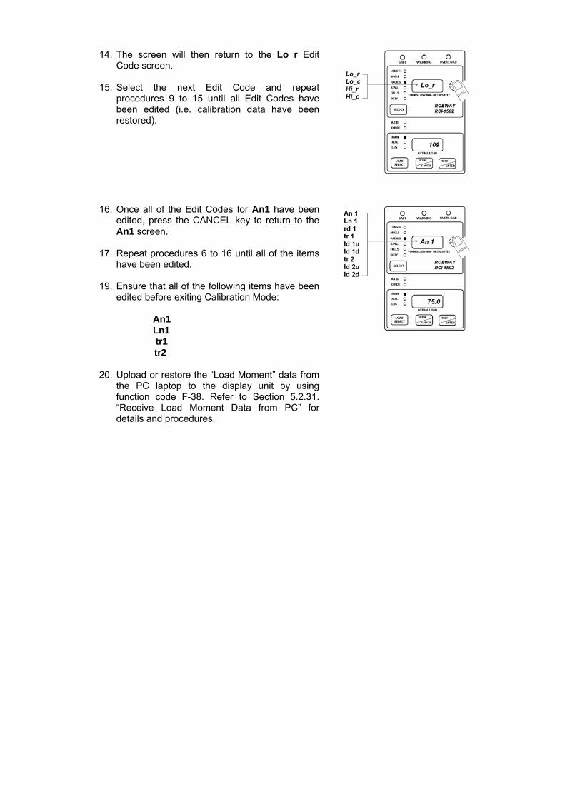
14. The screen will then return to the Lo_r EditCode screen.
15. Select the next Edit Code and repeatprocedures 9 to 15 until all Edit Codes havebeen edited (i.e. calibration data have beenrestored).
16. Once all of the Edit Codes for An1 have beenedited, press the CANCEL key to return to theAn1 screen.
17. Repeat procedures 6 to 16 until all of the itemshave been edited.
19. Ensure that all of the following items have beenedited before exiting Calibration Mode:
An1Ln1 tr1 tr2
20. Upload or restore the “Load Moment” data fromthe PC laptop to the display unit by usingfunction code F-38. Refer to Section 5.2.31.“Receive Load Moment Data from PC” fordetails and procedures.

6. Troubleshooting
The RCI-1502 system incorporates a number of software features that are designed to help the service person quickly identify a fault, however it must be stressed that these features cannot identify everything. They can only be used as a guide to identify additional checks that can be made. Some notes are provided below, followed by some example faults and possible causes.
1. Identify the symptoms. Take time to find out exactly what is happening to
indicate a problem. If possible have the problem demonstrated so you can "describe it in your own words". Sometimes what someone else has told you is only part of the story.
2. Leave the calibration alone! Too many times a re-calibration has been
attempted in order to rectify a problem before that problem has been correctly identified. This leads to added confusion as the perspective is generally moved from the real fault to "calibration problems". We have often received a message indicating that our display has "not accepted the calibration data". Most times this is due to a fault in a cable or sensor which was not identified prior to re-calibration. Re-calibration must only be performed when all physical inputs have been verified for correct operation, and in actual fact is rarely ever needed.
3. Do you have your simulator with you? A simulator is a very quick way to
verify if the fault is external to the display and will save you a lot of heartache.
4. Have you read the manual? When all else fails, read the manual! Your
answer may actually be in there. 5. Know what information you need to gather. If you collect the correct
information from the display the job is half done. Before you begin to suspect faults with the system, you must satisfy yourself that the display is correctly configured for the crane environment. In other words, check that the correct duty, falls, winch etc. have been selected. Are all of the sensors connected? In general if sensors have been supplied with the system, they must always be connected. The display will check them continuously and issue an error if that sensor cannot be detected. Check your length, angle and radius against the chart to verify that the equipment is permitted to be in that situation. If there is still a problem once these have been checked, then you will need to check the hardware.
6. The main pieces of useful information obtainable from the displays are
the raw counts. The raw count shows what the actual inputs are doing (i.e. like a signal strength indication). These raw counts are manipulated in software according to the calibration data stored in the display to produce the readouts on the Display Unit. If the calibration has been done incorrectly, or the configuration is incorrect, or something else is wrong, then the Display Unit readouts (e.g. the LOAD or ANGLE values) may provide you with misleading information.

YOU MUST USE THE "VIEW UNCALIBRATED...." FUNCTION CODES TO DETERMINE THE CORRECT OPERATION OF THE EXTERNAL SENSORS, NOT THE "CALIBRATED" VALUES. It should be noted here that for load related problems, the "VIEW UNCALIBRATED TRANSDUCER" function code must be used, and not "VIEW CALIBRATED LOAD". For correct operation these values must be in the range of 32 to 999 raw counts. Anything outside of this range will produce an error. Refer to Section 5. “Calibration” on how to access these raw counts.
7. Check the obvious. Once you have found a problem with a sensor forexample, check all of the obvious things to do with that sensor such asmaking sure all of the connectors are tight. Be systematic - make notesabout what you have done and what you found. You will find that underpressure you can easily forget what you have checked and it becomes veryeasy to miss things.

EXAMPLE PROBLEMS AND POSSIBLE CAUSES
Problems That Produce Error Codes:
Error code 320.
This is indicating that the Duty and/or Winch selected has not been calibrated.
Possible causes: Uncalibrated Duty and/or Winch selected.
Error code 101.
This is indicating that the signal from the angle sensor is too low or too high. This should be confirmed by viewing function code (F-07) “VIEW UNCALIBRATED ANGLE INPUT” and noting that the value shown on the LOAD LCD display is less than 33, or higher than 999.
Possible causes: Angle sensor incorrectly mounted. This is especially critical for the
Electronic Angle Sensor. Refer to Section 4. “Installation” of the manual for installation of the angle sensor.
The angle sensor signal wire is short circuited to the shield, theangle 0V, or the excitation positive wire.
The angle sensor is not connected or there is an open circuit ineither the angle sensor signal wire or the angle excitation positive wire.
The angle sensor excitation voltage is shorted. If this is the case itwill also affect the length and load channels.
The angle sensor 0V wire is open circuit.
Error code 110.
This is indicating that the signal from the length sensor is too low or too high. This should be confirmed by viewing function code (F-11) “VIEW UNCALIBRATED BOOM LENGTH INPUT” and noting that the value shown on the LOAD LCD display is less than 33, or higher than 999.
Possible causes: The length potentiometer may not have been set up as per the
manual. Refer to Section 4. “Installation” of the manual for installation of the angle sensor.
The length sensor signal wire is short-circuited to the shield, thelength 0V, or the excitation positive wire.
The length sensor is not connected or there is an open circuit ineither the length sensor signal wire, the length excitation positive wire, or the length 0V wire.
The length sensor excitation voltage is shorted. If this is the case, itwill also affect the angle and load channels.
Payout cable may have broken.

Error code 201. This is indicating that the signal from the pressure transducer 1 (bore or force side) is too low or too high. This should be confirmed by viewing function code (F-15) “VIEW UNCALIBRATED TRANSDUCER 1 INPUT” and noting that the value shown on the LOAD LCD display is lower than 33, or higher than 999. Possible causes: Force transducer signal wires shorted together. The signal + is shorted to the shield. The excitation - is shorted to the shield. The excitation supply is shorted together. This will obviously affect
all of the external sensors. Measure the excitation voltage and compare it with the expected value. If this is the cause, the UNCALIBRATED value will generally be non-zero, but below 33.
The force transducer is disconnected or there is an open circuit in one of the signal wires.
The signal - is connected to the shield. The signal + and the excitation + are swapped. The signal - and the excitation - are swapped.
Error code 202.
This is indicating that the signal from the pressure transducer 2 (annular or rod side) is too low or too high. This should be confirmed by viewing function code (F-19) “VIEW UNCALIBRATED TRANSDUCER 2 INPUT” and noting that the value shown on the LOAD LCD display is lower than 33, or higher than 999. Possible causes: Rod transducer signal wires shorted together. The signal + is shorted to the shield. The excitation - is shorted to the shield. The excitation supply is shorted together. This will obviously affect
all of the external sensors. Measure the excitation voltage and compare it with the expected value. If this is the cause, the UNCALIBRATED value will generally be non-zero, but below 33.
The rod transducer is disconnected or there is an open circuit in one of the signal wires.
The signal - is connected to the shield. The signal + and the excitation + are swapped. The signal - and the excitation - are swapped.
Error code 240.
This is indicating that an overload has been detected. This error generally accompanies most other errors simply because most other errors will place the display into an overload condition. This being the case, you need to check what other errors are present and correct them first. Once these have been addressed the E240 error generally takes care of itself. The exception is of course, when the equipment has been put into a genuine overload situation which has not been caused by any external faults.

Possible causes: A genuine overload condition exists. It has been caused by another Error code condition.
Error code 301.
This is indicating that the angle being measured is outside of its allowed range.
Possible causes: A genuine violation of the angle limits has occurred. The angle sensor mounting may have loosened allowing the sensor
to move. Wrong duty selected. Check the angle displayed against the actual angle of the boom.
Error code 302
This is indicating that the length being measured is outside of its allowed range.
Possible causes: A genuine violation of the length limits has occurred. The length potentiometer mounting may have loosened allowing the
sensor to move. Wrong duty selected. Check the length displayed against the actual boom length. Payout cable may have fallen off the reeling drum. Payout cable may have been broken or become tangled.
Error code 304.
This is indicating that the radius being measured is outside of its allowed range.
Possible causes: A genuine violation of the radius limits has occurred. Wrong duty selected. Check as per Error code 301 and 302.

Problems That Do Not Produce Error Codes: The load does not vary when I lift a weight.
The load cable and/or the load sensor is/are faulty. Check the load cable for faults. If cable is good, check the resistance values of the load cell. This, however, does not give the complete story. Even if the resistances are correct, there is still a chance that a fault on the sensor exists. Replace the load cell.
When the system starts in the morning the displays are erratic, but settle during the day.
This is a common sign of moisture ingress into either the display, the connectors, the sensors or the cable. These should be checked, dried and sealed.
The display does not start. You should check the power supply. The RCI-1502 has a voltage range of 10 – 40 vdc. If the supply is within range, open the Switchbox and check the fuses.
The unit is on alarm, but no error code on display.
Check for Two blocking condition. If no Two Blocking condition exist but the ATB LED on display is
ON, check the “earth lead” from the display for proper grounding to crane chassis.
If “earth lead” is OK, check the ATB switch and cable for faults.
On start-up the display shows “LCtrl” on top screen and then hangs (boot
up not completed).
This is a data logger control error. It happens when the internal data logger has been corrupted; when an upgraded or new software has been installed; or when the memory chip (Dallas IC) has been replaced with a new one.
To fix this error, insert and turn the override (bypass) key ON, then press the ENTER button. The display will show “YES” to confirm. While “YES” is shown on the screen, press the ENTER button again until the display gets into the normal initialisation/ set-up routine and then to normal operating mode.

7. Electrical Specifications
Power Supply Input (VDC) Range: 10 VDC - 40 VDC
Power Consumption < 1 amp (in full alarm)
Temperature Range Operating: -20C to +70C
Digital Inputs Total of three (3) digital inputs for connecting slew/proximity switches for monitoring different zones of operation, and/or for connecting other types of switches for any special crane requirement/application. Refer to Section 4. “Installation” of the manual for application details.
Motion Cut Relay Output One (1) standard motion cut relay output available for wiring to crane lockout solenoids to inhibit crane motion when on overload/alarm condition. The relay fitted in the Switchbox is rated 10A @ 30 VDC. A spare 12 VDC relay is also supplied with the installation kit for use on 12 VDC cranes. Refer to Section 4. “Installation” of the manual for application details.
Sensors
Pressure Transducers Capacity: 5000 PSI (34.5 MPa) Excitation Voltage: 4.0 VDC regulated (provided by the Display unit) Linearity: 0.15% nominal Repeatability: > 0.10% Hysteresis: < 0.10% Creep: < 0.10% Output: 2 mV/V nominal Isolation: > 2000 MOhms at 50 VDC Overload: 150% (no electrical damage)
> 400% (ultimate) Temperature Effects:
On Zero: < 0.006% / C On Span: < 0.005% / C
Compensated Range: -10C to +70C Sealing: IP68 fully encapsulated Pin/Wire Connections (5-Way Connector):
Pin A Black Negative Excitation Pin B White Negative Signal Pin C Red Positive Excitation Pin D Green Positive Signal Pin E Screen Screen

Expected Resistances (for a standard 350-Ω cell): Red - Black 300 - 600 Ω Red - Green 200 - 400 Ω Red - White 200 - 400 Ω Black - Green 200 - 400 Ω Black - White 200 - 400 Ω White - Green 350 Ω ± 2 Ω
Shield/Screen to any other wire must be open circuit
Electronic Angle Sensor Type: Capacitance-based sensor with no moving parts,
ratiometric output Excitation Voltage: 4.0 VDC regulated (provided by the Display unit) Operating Range: +/- 45 (offset mounted to accommodate 0 - 90) Accuracy: +/- 0.2 Cable Entry: Mil-spec plug/socket connector (Angle Sensor& Length
Sensor are joined in one cable and connector from the Recoil Drum)
Mounting: Via screws inside the Recoil Drum Weight: 0.3 kg Pin/Wire Connections (7-Way Connector, joined with Length Sensor):
Pin A Red Positive Excitation Pin E White Angle Signal Pin C Black Negative Excitation
Expected Resistances: High ohms or open circuit between any of the wires and chassis or shield
Boom Length Sensor Type: 500-ohm 10-turn potentiometer Excitation Voltage: 4.0 VDC regulated (provided by the Display unit) Operating Range: 0-30 metres Accuracy: +/- 0.05 metre Cable Entry: Mil-spec plug/socket connector (Angle Sensor& Length
Sensor are joined in one cable and connector from the Recoil Drum)
Mounting: Via screws inside the Recoil Drum Weight: 0.1 kg Pin/Wire Connections (7-Way Connector, joined with Angle Sensor):
Pin A Red Positive Excitation Pin B Blue Length Signal Pin C Black Negative Excitation
Expected Resistances: High ohms or open circuit between any of the wires and chassis or shield
Proximity Switch Type: PNP – N.O. & N.C. Sensing Range: 10 mm Operating Voltage: 10 – 30 VDC Switching Current: 200 mA maximum

Anti-Two-Block Switch (Model BB5) Type: V4 IP67 sealed, leaf Contact Rating: 28 VDC/3A Electrical Life: 105 operations Operating Force: 0.6 N (max) Release Force: 0.08 N (min)
Cables General: 2-, 4-, 6-, & 10-core braided, UV stabilised, PVC
sheathed cables DC Resistance: 38.2 ohms/km @ 20C (25.45 ohms/km for 2-core cable) Core Insulation: V90-HT PVC (designed to comply to AS/NZ 3808:2000) Electrical Life: 105 operations Cable Integrity: All cores tested for insulation resistance @ test voltage
of 500V Sheath: Overall 5V90 UV stabilised PVC Current Rating: 3 amps Capacitance: 150 pf/m (core to core)

Robway Crane Safety Systems Pty Ltd Adelaide, South Australia
RCI-1502 LM Tele Boom Manual
8. Appendices 8.1. DATA LOGGING ON RCI SYSTEMS 8.2. DRAWINGS 8.3. RCI SYSTEM CRANE CONFIGURATION SHEET / DUTY LISTING / FUNCTION CODES
jon
Rectangle

Appendix 8.1.
Data Logging on RCI Systems
jon
Rectangle


Data Logging on RCI Systems
Introduction
The RCI System Logging occurs automatically whenever the driver lifts a load OR whenever the RCI System detects an error condition on the crane such as moving outside the load chart. The installer has the option to set the percentage of SWL a load must reach before the load will be logged. This logging percentage can be set anywhere between 13% and 110% of SWL.
In addition, the installer can configure three lift counters which can count the number of lifts performed in three distinct SWL % regions below the logging percentage.
Description of Logging Features
Data Logging is stored in a circular arrangement. That is, when the logs are full and another log is performed, the oldest log in the logger will be over-written. Each record stores the following data:
Date Date log was recorded (dd/mm/yyyy) Time Time log was recorded (hh:mm) Peak Load Peak load recorded during log cycle Stable Load Maximum Stable load recorded during log cycle Safe Working Load SWL at operating position Percent of SWL Percentage of SWL Radius Operating RadiusError Codes 4 digit standard Robway Error Codes Duty Number Selected Duty number Winch selected Selected winch Falls reeved Selected falls Over-ride state Off / On indicates whether display was in over-
ride
Logging is performed automatically when the percentage of SWL exceeds a threshold value which is set in Function Codes.
When the logging percentage is not exceeded while lifting a particular load, the lift occurrence can still be recorded in a lift counter. Three separate lift counters can be configured to store the number of lifts which occur in a particular SWL % region. Once again, the exact SWL percentages which will be counted can be configured by setting the appropriate Function Codes.

Data Logging on RCI Systems
A summary of the logging percentage Function Codes is displayed in the following table:
Function Code Name Description Default Setting Low Load Lift counter swl percentage to record 20.0% Medium Load Lift counter swl percentage to record 40.0% High Load Lift counter swl percentage to record 65.0% Logging Percentage swl percentage to log 90.0%
These default settings would give rise to the following logging operation:
Low Load Lift Counter counts the number of lifts which produce a SWL % which is greater than or equal to 20% but less than 40%.
Medium Load Lift Counter counts the number of lifts which produce a SWL % which is greater than or equal to 40% but less than 65%.
High Load Lift Counter counts the number of lifts which produce a SWL % which is greater than or equal to 65% but less than 90%.
Logger Records full configuration data of any lift which produces a SWL % which is greater than or equal to 90%
Setting Up the Data Logger
Data logging will occur at all times the display is operational. This includes the cases when, the over-ride is activated, the display is reporting an error and during the initial calibration of the system.
For the Logger to operate properly the display must be fully and correctly calibrated. However, since the logger was recording during calibration it is probably desirable to erase the logger contents after completing the angle and load calibrations on the RCI System since the logger would have recorded some invalid information during the calibration of the sensors.
To erase the data logger contents, simply activate the appropriate Function Code once calibration is complete (refer to Function Codes list at the rear of the Manual for the appropriate code).
The operator can access three more Function Codes which control how the actual logging of loads operates. These three Function Codes are summarised in the following table
Stable Load Time time during which load must stay stable in order to log Stable Load Variation load must stay within this variation to be considered stable Reset Time load must stay below the Low Load Counter threshold for this
time before the log cycle ends

Data Logging on RCI Systems
The first two Function codes in the table are used for determination of a stable load. When a load is hoisted it is probable that the initial load reading will be greater than the actual load on the hook because of the "snatching effect". The stable load is recorded only when these dynamic factors have died down and the load can be considered to be hanging from the hook in a relatively motion free position.
The "Stable load time" and "Stable load variation" Function codes can be used to adjust the load recording to minimise the effect of dynamic factors. The load will be considered stable if the load reading does not change by more than the "Stable load variation" setting (which is 0.1t by default) for a period of time set by "Stable load time" (which is 2 seconds by default).
The third Function code, "Reset time," is used for terminating a lift. When the load causes a SWL % which is less than the logging values (specifically the Low Load Lift counter percentage), then it is assumed that the driver must be putting the load down again. In order to ensure that a single load is not logged multiple times because the SWL % was hovering around the logging threshold, a log cycle will not complete until the load SWL % remains below the threshold for a certain period of time, namely of course the "Reset time" (by default the reset time is set for 5 seconds).
Log Cycle Description
Two types of log cycles are possible:
1. Load is lifted inside load chart boundaries (valid SWL is seen at all times).2. SWL drops to 0 indicating the load chart has been exceeded, sensor error has
occurred or slew error has occurred.
Type 1 Log- Valid SWL cycle
A log cycle is started when:
• the current SWL % (load/swl) exceeds the THRESHOLD (which will be the valueset for the Low Load Lift Counter function Code).
During a log cycle:
• the load is monitored, the peak load seen is continually updated and if no stableload has been recorded then all other data is recorded against peak load.
• a stable load condition will apply when the load remains within a small variationrange (set by user through F-Code "Stable Load Variation") for a certain period oftime (also an F-Code "Stable Load Time").
• when a stable load is seen, all data (except peak load) are recorded against thestable load.

Data Logging on RCI Systems
• load monitoring continues, the SWL percentage is continually checked against theSWL percentage which was stored, if the percentage increases, a new stable loadwill be recorded.
A log cycle is completed when:
• the current SWL % drops below the THRESHOLD for a period of time set by theReset Time Function Code
OR • the SWL drops to 0 initiating a Type 2 Log cycle.
In either case, the currently performed log will be stored prior to initiating a new cycle.
Type 2 Log- Out of Load Chart / Error conditions
A log cycle is started when:
• SWL drops to 0, implying SWL % is unknown but definitely greater than 110%.In this case the SWL is nominally set to 110% and appears as ">110%" in thelogger print out.
During a log cycle:
• the load is monitored and the peak load seen is continually updated (in log 1).• the radius is monitored and the max. radius seen is continually updated (in log 2).
A log cycle is completed when:
• SWL becomes > 0 (log 1 AND log 2 are stored and condition for starting a type 1log is checked).
Hence, if a load is lifted within the load chart a single log is performed. If the boom is positioned outside of the load chart, any log cycle in progress is stored and a new cycle begins. During this overload cycle two individual logs will be performed. One log will record the maximum load reading which is observed and the other will record the maximum radius which is observed. It is necessary to perform two logs because it is impossible to know which is a more unsafe condition, a longer radius or a shorter radius but higher load on the hook.
Stable loads are not monitored during out-of-chart/error logging cycles.

Data Logging on RCI Systems
Example Load Lift Suppose a driver lifts a load and luffs out. If we assume the SWL % generated at the edge of the load chart is sufficient to cause a log to record then as soon as the driver exceeds the maximum radius on the chart, the active log cycle completes and is written to the logger prior to beginning an "out-of-chart" log cycle. The out-of-chart cycle continues until the driver luffs the crane back into a safe condition. As soon as the safe condition is achieved, the out-of-chart logs (one for max. load and one for max. radius) will be stored to the logger. Because the crane is now back in a safe condition, a new logging cycle begins. When the driver finally puts this load down (assuming he does not luff off the chart again) the normal log cycle completes and another log is written to the logger. Hence, although the driver has lifted only a single load and luffed it to several positions, the actual load has been recorded a total of 4 times. This example serves to illustrate that if the crane is continually working on it's outer radius, the Logger will fill very quickly. It should be noted that if motion cut is connected and the display is not in over-ride, luffing to the out radius limits of the load chart could cause the crane to oscillate as motion cut activates. In this case many logs may be recorded.

Data Logging on RCI Systems
Example Lift Cycles

Data Logging on RCI Systems
Accessing the Data Logger
When the RCI System is powered on the normal check routines are performed. If your display has logging enabled then the percentage of the logger which is full is displayed on start up in the LOAD window. The display will show the prompt "=LE=" if the logger is completely empty, otherwise the prompt "LXXX" will show where XXX is the percentage of the logger which is currently filled.
The operator can use two more Function codes for accessing the information stored in the data logger. These Function codes are used for:
Downloading the data logger records to a PC, and Erasing the content of the data logger
Downloading Data Logger Information
Downloading of data logger records can be performed at any time by attaching the cable provided between the RCI System and a standard PC or laptop and selecting the "Download Log Data" Function Code (refer to Function Codes list at the rear of the Manual for the appropriate code).
Communication Settings
The download is performed as an ASCII file transfer which means any standard terminal emulator software (e.g. simterm, procomm, etc.) or the standard Hyper-Terminal program of Windows (98, XP, etc.) could be used to receive the information from the RCI System.
Communication Settings for the transfer are:
Baud Rate = 9600 Data Bits = 8 Parity = none Stop Bits = 1

Data Logging on RCI Systems
Downloaded Data Format
Each record will be printed in chronological order followed by a summary on the contents of the data logger. If no records have been stored a message to this extent is displayed on the RCI calibration window however, the summary information is still downloaded to the PC.
The summary consists of 6 lines of information as follows:
1. DOWNLOAD PERFORMED (date time) 2. Percentages Changed (date time) *** 3. No. Lifts in range 20% to 40% SWL = xx4. No. Lifts in range 40% to 65% SWL = xx5. No. Lifts in range 65% to 90% SWL = xx6. No. Lifts logged with > 90% SWL = xx
*** Note: Default date if percentages have not been altered from Robwaysettings is 01/01/96.
The first line simply states the date and time of when the download was performed.
The second line shows the date and time of when the percentage values for the counters and/or the logging percentage were last changed. The default date displayed is the 01/01/96. If the percentages are changed, the new date and time will be stored. This date and time will be maintained until the values are once again altered or calibration data is cleared.
The third, forth and fifth lines give counts of the total number of lifts performed in the specified regions of SWL %. The percentages shown in this table can of course be changed in Function codes (causing the date in the second line to change as just discussed).
The sixth line gives a count of the number of full logs which have been performed and printed.
The records are printed 1 per line with each field in the record separated by a tab character. This means the resultant file stored on the PC is a tab de-limited text file which is a suitable format for importing into spreadsheet programs such as Microsoft Excel.
Generally spreadsheet programs will automatically recognise the file format as a tab de-limited text file and promptly convert the data into a spread sheet format. In some cases it may prove necessary to ensure the file is saved with a .txt extension name which is the standard extension for ASCII text files.

Data Logging on RCI Systems
Downloading of the logger can be performed any number of times without affecting the contents of the logger. Generally however, after downloading is performed, it is normally desirable to erase the contents of the logger.
Downloading takes approximately 15 seconds per 100 records.
Erasing Data Logger Information
Erasing of data logger records can be performed at any time by accessing the Function Code for "Erasing Log Data" (refer to Function Codes list at the rear of the Manual for the appropriate code).
Erasing the data logger will cause all currently recorded logs to be erased (hence the information can no longer be downloaded) and it also clears the SWL % counters.
In effect, the logger is now empty, however, the old records in the data logger have not really been erased, simply the program log counters have been erased. Hence, in the event that the data logger has been erased but the information has not been saved it is possible to have the data extracted from the logger by sending the display to Robway for analysis.

Data Logging on RCI Systems
Errors in Logger Data
On powering the display the contents of the data logger is checked in three separate operations. In 99% of cases these checks will all pass OK. If however a check fails the state of the logger is immediately questionable. Where possible the operator is given the choice of erasing the suspect data, however, in some instances, the logger will automatically be erased.
If you observe an error and have the option to erase the logger contents, we recommend you don't immediately erase the logger if there is desired information stored there, but rather download the data before then erasing.
These errors should not occur except in extenuating circumstances. If you have trouble with log errors you should immediately report such errors to Robway along with the pertinent information about your display (display serial number & software number)
Firstly, the control structure for the data logger is checked. If an error is found in the control structure for any reason, then the display AUTOMATICALLY ERASES data logger contents (because future logging is not reliable). If this error occurs the message:
LOG CONTROL ERR! RESETTING LOGGER
is displayed in the calibration window. The only way to retrieve any data in the logger in this case is to send the display to Robway for analysis.
Secondly, the actual data in the logger is checked for errors. In the case that the data is found to be suspect then the message:
LOG DATA ERROR! <ENTER> to ERASE
is displayed in the calibration window. In this event the user is prompted as to whether to erase the logger contents. Ideally the data should be erased since it is not totally reliable however, the choice is presented so as to give the opportunity to download the information prior to erasing the data (note erasing the data also clears the lift counters).
Lastly, the lift counters are checked for errors. Once again, if an error is found the user has the choice of erasing the counts or ignoring the error.
LOG COUNT ERROR! <ENTER> to ERASE
If the error is ignored, the count values cannot be relied upon as correct.

Appendix 8.2.
Drawings


RE
VD
AT
ED
ES
CR
IPTIO
N O
F C
HA
NG
EA
PP
RV
'DD
RA
WN
BY
AP
PR
OV
ED
BY
PA
RT O
F AS
SY
PA
RT N
o:P
RO
JEC
T:
TITLE:
SC
ALE
SH
EE
T
RE
VFILE
No:
DR
AW
ING
No:
OF
web : w
ww
.lsirobway.com
.au
32 West Thebarton R
dTH
EB
AR
TON
SO
UT
H A
US
TRA
LIA 5031
PH
ON
E: +61 8 8238 3500
FAX
: +61 8 8352 1684 c copyright robw
ay 2005
X.
X.X
X.X
X
TOL:
+/-1+/-0.2+/-0.02
DO
NO
T SC
ALE
DR
AW
ING
ALL D
IME
NS
ION
S A
RE
IN M
ILLIME
TE
RS
UN
LES
S O
THE
RW
ISE
ST
ATE
D
N/A
S. C
HA
MB
ER
S
7/02/2006
1.0333601A
A.idw
WIR
ING
DE
TA
IL
SW
ISB
1502V2
1502 SW
ITCH
BO
X (V
ER
SIO
N 2)
1 1
DW
G 3336
-
BLACK
EX
TE
RN
AL A
UD
IBLE
ALA
RM
SP
AR
E (B
LUE
)B
UZZ
ER
(GR
EE
N)
MO
TION
CU
T (Y
ELLO
W)
INP
UT A
(VIO
LET
)
INP
UT C
(WH
ITE)
OV
ER
IDE
(PIN
K)
PO
WE
R - (B
LAC
K)
MO
TIO
N C
UT (N
/C)
RED
PINKWHITE
ORANGEVIOLET
YELLOWGREEN
BLUE
KE
YS
WITC
H
BLA
CK
BROWN
INP
UT B
(OR
AN
GE
)10 C
OR
E D
ISP
LAY
INTE
RFA
CE
CA
BLE
RE
LAY
1(G
RE
EN
)R
ELA
Y 2
(YE
LLOW
)R
ELA
Y 3
(RE
D)
RE
LAY
4(A
LAR
M)
RE
LAY
5(M
OTIO
N C
UT)
SU
PP
LY -V
E (B
LAC
K)
MO
TIO
N C
UT
(N/O
)M
OTIO
N C
UT (C
OM
MO
N)
EX
TE
RN
AL A
LAR
M (N
/O)
EX
TER
NA
L ALA
RM
(CO
MM
ON
)
EX
TER
NA
L WA
RN
ING
LIGH
T (R
ED
)E
XTE
RN
AL W
AR
NIN
G LIG
HT (Y
ELLO
W)
EX
TER
NA
L WA
RN
ING
LIGH
T (GR
EE
N)
EX
TER
NA
L WA
RN
ING
LIGH
T (CO
MM
ON
)
OV
ER
IDE
KE
YS
WITC
H(S
WIK
A3368)
PO
WE
R + (R
ED
)
J3
2 CO
RE
CA
BLE
(VD
C P
OW
ER
INP
UT)
(CA
BP
1206)
SU
PP
LY +V
E (R
ED
)
PIN
K
SP
AR
E (B
RO
WN
)
SU
PP
LY +V
E
SU
PP
LY -V
EIN
PU
T A
INP
UT C
INP
UT B
CU
STO
ME
R W
IRE
D(U
NLE
SS
OTH
ER
WIS
ER
EQ
UE
ST
ED
)
INS
TALLA
TION
NO
TES
:1.TH
E M
OTIO
N C
UT O
PT
ION
IS R
ATE
D FO
R 10A
30V M
AX
. EN
SU
RE
THA
T THE
SO
LEN
OID
DO
ES
NO
T E
XC
EE
D TH
IS R
ATIN
G.
2. THE
INP
UTS
MA
RK
ED
AS
"A", :B
", AN
D "C
" AR
E G
EN
ER
AL P
UR
PO
SE
INP
UTS
. TH
EIR
FUN
CTIO
N A
RE
D
EFIN
ED
IN TH
E S
OFTW
AR
E D
ES
PA
TC
HE
D F
OR
A P
AR
TICU
LAR
AP
PLIC
ATIO
N. R
EF
ER
TO TH
E
CO
NFIG
UR
AT
ION
SH
EE
T IN T
HE
MA
NU
AL FO
R TH
EIR
DE
FINIT
ION
.3. P
RE
VIO
US
DE
FAU
LT DE
FINIT
ION
FOR
THE
INP
UTS
WE
RE
: - IN
PU
T "A": M
AIN
DIR
EC
TION
, CLO
SE
D = D
OW
N.
- INP
UT "B
": AU
XILLA
RY
DIR
EC
TION
, CLO
SE
D = D
OW
N.
- INP
UT "C
": SLE
W S
WIT
CH
, GE
NE
RA
LLY O
PE
N P
RO
DU
CE
D A
DE
-RA
TING
.4. A
LL SLE
W S
WITC
HE
S M
US
T BE
RA
TE
D A
T 35V
OR
MO
RE
TO
AV
OID
DA
MA
GE
TO TH
E S
WITC
H.
SU
PP
LY +V
E
SIG
NA
L OU
T
SU
PP
LY -V
E
BR
OW
N
BLA
CK
BLU
E
SU
PP
LY +V
E
INP
UT "A
", "B" O
R "C
"
SU
PP
LY +V
E
SIG
NA
LD
ES
CR
IPTIO
NC
OLO
UR
(TY
PIC
AL)
CO
NN
EC
TION
INS
WIT
CH
BO
X
PR
OX
IMITY
SW
ITCH
WIR
ING
BLACKRED
3.15A FU
SE
(PO
WE
R)
SH
OR
TIN
G P
AT
CH
FOR
-E
NA
BLE
EX
TER
NA
L ALA
RM
IN S
ER
IES
WITH
RE
D W
AR
NIN
G LIG
HT
(RL4)
24V R
ELA
Y IS
INS
TALLE
D A
S S
TAN
DA
RD
UN
LES
SO
TH
ER
WIS
E S
PE
CIFIE
D.
(12V R
ELA
Y S
UP
PLIE
D IN
INS
TALLA
TION
KIT
)
EX
TE
RN
AL W
AR
NIN
G LIG
HT R
ELA
YS
(RE
LAY
1, 2 & 3)
EX
TE
RN
AL A
LAR
M R
ELA
Y(R
ELA
Y 4)
NO
TE: R
ELA
YS
(RE
LSV
SP
CO
) ON
LY IN
ST
ALLE
D
UP
ON
CU
ST
OM
ER
RE
QU
ES
T

UNCO
NTRO
LLED
COPY

AP
PR
OV
ED
BY
!"
# $
% % &'(
)
*( + ++ &''
, )
*( + +& (*+
,-
,-,
,-,,
TOL:
)./(
)./'
-)./'
-'
((''
0
00
%
-!"
(+.'(.'(
(-'
&1*'(-2$3
4"!55
26#2
# !
#$ 07#2#
8 #"
%9'(
(
(
&1*
'-'
1'-'
&'-'
+-&('-&
('-'
(+'-'
(-1
(1-'
('*-
0(.+
" !:7 ;!
5
(6 <#2
#


AP
PR
OV
ED
BY
!"# $
% % &'(
)*( + ++ &''
, )*( + +& (*+
,-
,-,
,-,,
TOL:
)./(
)./'-
)./'-'
((''
0
00
%
-
(1.'(.'(
(-'
&22'(-3$4
5 6 0%
/
(
(
&22
'-'
(&-'
(&-'
''-'
(2-'
1'-' 7" *8 $"98
1'-' 7" &8 $"98
'-' 7" *8 $"98
&'-' 7" &8 $"98
(1'-'
+-&
'-'
0(.+
':
" !;9 <! =
*8 >#3# 6 &8
>#3#
%?'*.%?'&


!
"
#
#
"
"
"
#
#
$
%
"
AP
PR
OV
ED
BY
$
&'
('
'
$&'
"&'
$
")*+,)-./+&01
2
'!22
$'!!
3
3
3
TOL:
4#
4#23
4#232
$'22
"
"
(3
24242
32
23516
7!87 79
2!
!!
(3
4242


!
"
"
#
#
$
%
!
AP
PR
OV
ED
BY
$
&'
('
'
"
$&'
!&'
$
!
)*+
,)-./+&
01
2
'
22
$'
"
3
3
3
TOL:
4#
4#2
34#2
32
$'
22
!
!
5&,0,
"4242
"#3617
8
98
8
:
!
2#
"


ENSU
RE
THAT
TH
E REC
OIL
DRU
M I
S M
OU
NTE
D V
ERTI
CALL
Y AN
D
THAT
TH
E D
IREC
TIO
N T
HE
CABL
E IS
PU
LLED
OFF
TH
E D
RU
M I
S IN
LIN
E W
ITH
TH
E BO
OM
. IF
IT C
OM
ES O
FF A
T AN
AN
GLE
TH
ERE
IS R
ISK
THAT
IT
WIL
L SL
IP O
FF T
HE
SID
E O
F TH
E D
RU
M.
STEP
1
ENSU
RE
CABL
E D
OES
NO
T G
ET C
AUG
HT
UP,
STR
ETCH
ED O
R
PIN
CHED
AT
PIVO
T AR
EA.
DAN
GER
AREA
!
STEP
2
PULL
PAY
OU
T CA
BLE
FULL
Y O
FF D
RU
M B
Y H
AND
.
FULL
Y EX
TEN
D B
OO
M
FULL
Y EX
TEN
D B
OO
M
ALLO
W 2
- 4
M T
O R
ETU
RN
O
NTO
DRU
M.
WRAP
CAB
LE 1
.5 T
URN
S AR
OU
ND
TH
E TI
E-O
FF B
RAC
KET
AND
CLA
MP
SECU
REL
Y. R
EMO
VE E
XCES
S CA
BLE
ON
LY I
F AT
B N
OT
INST
ALLE
D.
IF A
TB I
S IN
STAL
LED
LEA
VE
ENO
UG
H C
ABLE
TO
ATT
ACH
TO
TH
E AT
B SW
ITCH
.
ENSU
RE
THAT
ALL
CAB
LE G
UID
ES A
RE
IN A
ST
RAI
GH
T LI
NE
OR E
XCES
S W
EAR O
N T
HE
CABL
E W
ILL
OCC
UR.
3m M
INIM
UM
STEP
3
STEP
4
STEP
5
FULL
Y EX
TEN
D B
OO
M
DRAW
ING
No:
DES
CRIP
TIO
N O
F CH
ANG
EREV
DAT
EAP
PR'D
X.X
X.XX
DO
NO
T SC
ALE
DRAW
ING
ALL
DIM
ENSI
ON
S AR
E IN
MIL
LIM
ETER
SU
NLE
SS O
THER
WIS
E ST
ATED
TOL:
X.+
/- 1
AS S
TATE
D+
/- 0
.2
PART
OF
ASSY
APPR
OVE
DD
RAW
NPA
RT
NO
.:
-TI
TLE:
-
DW
G 3
718
FILE
No:
N/A
SHEE
TO
FREV
SCAL
E
1.0
14
PRO
JECT
:
DRAF
TIN
G S
TAN
DAR
D:
AS11
00
31/1
0/20
07S.
CH
AMBE
RS
3718
01AA
.DW
G
INST
ALLA
TIO
N D
ETAI
LSREC
OIL
DRU
MJ.
KO
VAL
1/11
/07
32 WEST THEBARTON RD
THEBARTON 5031
SOUTH AUSTRALIA
PHONE +61 8 8352 6055
LSI-ROBWAY
FAX +61 8 8352 1684

TIE OFF BR
ACKETCABLE G
UID
E(R
EFER TO
SHEET 4)
RECO
IL DRU
M
CL
NO
TE:TO
ENSU
RE CABLE FLEETS EVEN
LY OVER
DRU
M W
IDTH
. THE
CENTR
E OF TH
E CABLE GU
IDES M
UST BE FITTED
ON
THE
CENTR
E LINE O
F THE CABLE D
RU
M AS SH
OW
N.
WAR
NIN
G:
IF THE ABO
VE NO
TE IS NO
T SATISFIED, TH
E CABLE MAY O
VER
SPILL SIDES O
F THE D
RU
M FLAN
GE.
DRAW
ING
No:
DESCR
IPTION
OF CH
ANG
EREV
DATE
APPR'D
X.XX.XX
DO
NO
T SCALE DRAW
ING
ALL DIM
ENSIO
NS AR
E IN M
ILLIMETER
SU
NLESS O
THER
WISE STATED
TOL:
X.+
/- 1
AS STATED+
/- 0.2
PART O
F ASSYAPPR
OVED
DRAW
NPAR
T NO
.:
-TITLE:
-
DW
G 3718
FILE No:
N/A
SHEET
OF
REV
SCALE
1.0
24
PRO
JECT:
DRAFTIN
G STAN
DAR
D: AS1100
31/10/2007S. CH
AMBER
S
371801AA.DW
G
INSTALLATIO
N D
ETAILS
RECO
IL DRU
MJ. KO
VAL1/11/07

EXTE
NSI
ON
STD
. CAB
LE F
ITTE
D
CAN
BE
LEFT
HAN
D M
OU
NT
OR R
IGH
T H
AND
MO
UN
T D
EPEN
DIN
G O
N T
HE
APPL
ICAT
ION
.(L
EFT
HAN
D M
OU
NT
SHO
WN
FO
R I
ND
ICAT
ION
PURPO
SES
ON
LY).
JUN
CTIO
N B
OX
ATB
SWIT
CH
BOB
WEI
GH
T(C
HAI
N L
ENG
TH T
O S
UIT
CRAN
E)CA
BLE
GU
IDES
DRAW
ING
No:
DES
CRIP
TIO
N O
F CH
ANG
EREV
DAT
EAP
PR'D
X.X
X.XX
DO
NO
T SC
ALE
DRAW
ING
ALL
DIM
ENSI
ON
S AR
E IN
MIL
LIM
ETER
SU
NLE
SS O
THER
WIS
E ST
ATED
TOL:
X.+
/- 1
AS S
TATE
D+
/- 0
.2
PART
OF
ASSY
APPR
OVE
DD
RAW
NPA
RT
NO
.:
-TI
TLE:
-
DW
G 3
718
FILE
No:
N/A
SHEE
TO
FREV
SCAL
E
1.0
34
PRO
JECT
:
DRAF
TIN
G S
TAN
DAR
D:
AS11
00
31/1
0/20
07S.
CH
AMBE
RS
3718
01AA
.DW
G
INST
ALLA
TIO
N D
ETAI
LSREC
OIL
DRU
MJ.
KO
VAL
1/11
/07


RE
VD
AT
ED
ES
CR
IPTI
ON
OF
CH
AN
GE
AP
PR
V'D
DR
AW
N B
YA
PP
RO
VE
D B
YP
AR
T O
F A
SS
YP
AR
T N
o:P
RO
JEC
T:
TITL
E:
SC
ALE
SH
EE
T
RE
VFI
LE N
o:D
RA
WIN
G N
o:
OF
web
: w
ww
.lsiro
bway
.com
.au
32 W
est T
heba
rton
Rd
TH
EB
AR
TON
SO
UTH
AU
STR
ALI
A 5
031
PH
ON
E: +
61 8
823
8 35
00FA
X: +
61 8
835
2 16
84 c
copy
right
robw
ay 2
005
X.
X.X
X.X
X
TOL:
+/-1
+/-0
.2+/
-0.0
2
DO
NO
T S
CA
LE D
RA
WIN
GA
LL D
IME
NS
ION
S A
RE
IN M
ILLI
ME
TE
RS
UN
LES
S O
THE
RW
ISE
ST
ATE
D
N/A
S. C
HA
MB
ER
S
19/0
4/20
05
1.3
2934
01A
D.id
w
AS
SY
, BB
5 D
IME
NS
ION
AL
DE
TA
IL
SW
IBB
5B
B5
ATB
SW
ITC
H 1 2
2934
A. C
AN
LAS
19/0
4/20
05-
3RD
AN
GLE
1.1
16/0
7/10
EX
PLO
RE
D V
IEW
AD
DE
D R
EFE
R P
CR
#322
A.A
.
1.2
14/0
1/20
11R
EFE
R T
O P
CR
#366
A.A
.
1.3
24-1
-14
RE
FER
TO
EC
N 5
43J.
H
Par
ts L
ist
ITE
MQ
TYD
ES
CR
IPT
ION
DW
G N
o.P
AR
T N
UM
BE
R18
2C
AB
LE T
IES
TI
E20
0BK
4060
40
9
THR
U2
X
4 C
OR
E
SC
RE
EN
ED
CA
BLE
12
22
6
45
257
54
RXXXXXXX
EN
GR
AV
E S
ER
IEL
NO
. HE
RE
AD
D 2
CA
BLE
TIE
S T
O
HO
LD S
PR
ING
IN P
LAC
E
18