RCC T BEAM.xls
33
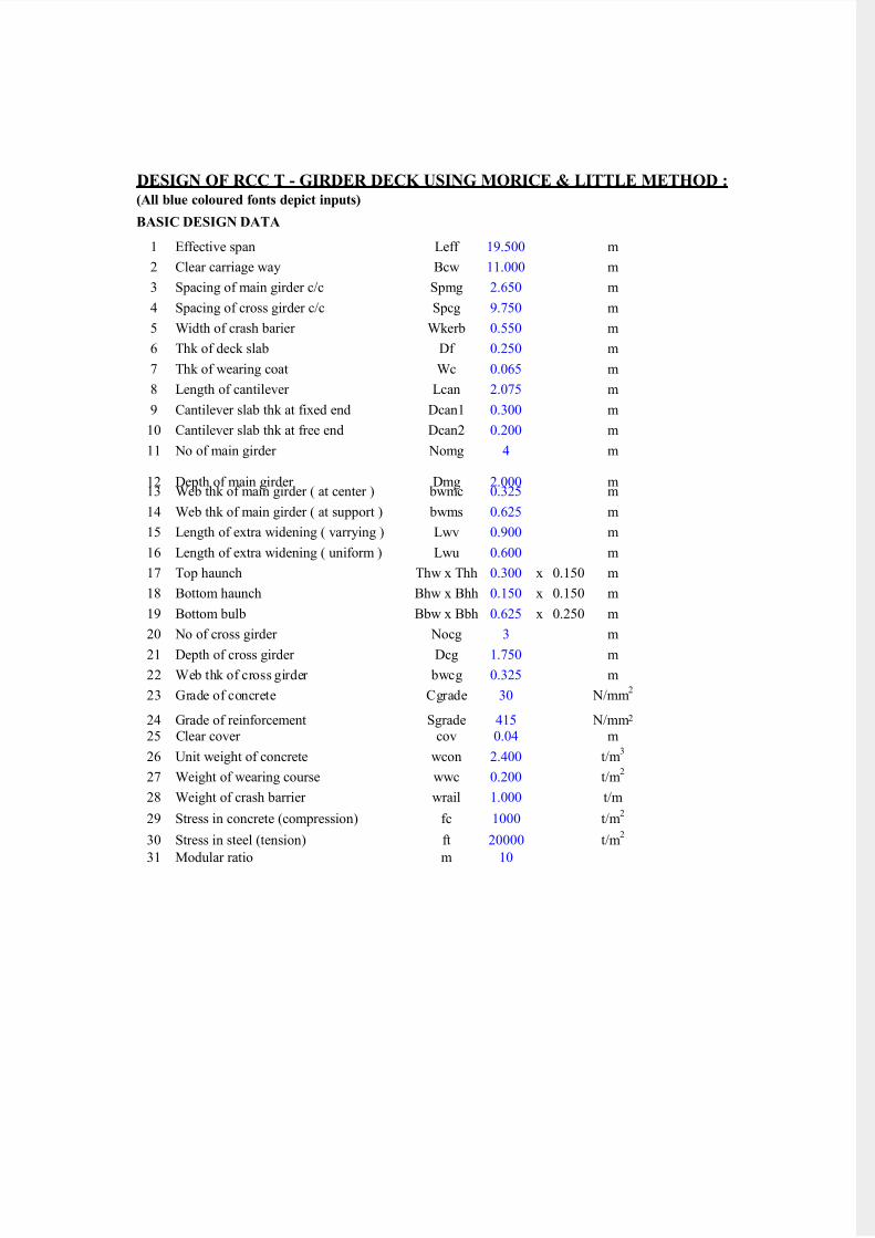
7/14/2019 RCC T BEAM.xls http://slidepdf.com/reader/full/rcc-t-beamxls 1/33 DESIGN OF RCC T - GIRDER DECK USING MORICE & LITTLE METHOD : (All blue coloured fonts depict inputs) BASIC DESIGN DATA 1 Effective span Leff 19.500 m 2 Clear carriage way Bcw 11.000 m 3 Spacing of main girder c/c Spmg 2.650 m 4 Spacing of cross girder c/c Spcg 9.750 m 5 Width of crash barier Wkerb 0.550 m 6 Thk of deck slab Df 0.250 m 7 Thk of wearing coat Wc 0.065 m 8 Length of cantilever Lcan 2.075 m 9 Cantilever slab thk at fixed end Dcan1 0.300 m 10 Cantilever slab thk at free end Dcan2 0.200 m 11 No of main girder Nomg 4 m 12 Depth of main girder Dmg 2.000 m 13 Web thk of main girder ( at center ) bwmc 0.325 m 14 Web thk of main girder ( at support ) bwms 0.625 m 15 Length of extra widening ( varrying ) Lwv 0.900 m 16 Length of extra widening ( uniform ) Lwu 0.600 m 17 Top haunch Thw x Thh 0.300 x 0.150 m 18 Bottom haunch Bhw x Bhh 0.150 x 0.150 m 19 Bottom bulb Bbw x Bbh 0.625 x 0.250 m 20 No of cross girder Nocg 3 m 21 Depth of cross girder Dcg 1.750 m 22 Web thk of cross girder bwcg 0.325 m 23 Grade of concrete Cgrade 30 N/mm 2 24 Grade of reinforcement Sgrade 415 N/mm 2 25 Clear cover cov 0.04 m 26 Unit weight of concrete wcon 2.400 t/m 3 27 Weight of wearing course wwc 0.200 t/m 2 28 Weight of crash barrier wrail 1.000 t/m 29 Stress in concrete (compression) fc 1000 t/m 2 30 Stress in steel (tension) ft 20000 t/m 2 31 Modular ratio m 10
description
RCC T BEAM DESIGN FOR BRIDGE
Transcript of RCC T BEAM.xls
7/14/2019 RCC T BEAM.xls
http://slidepdf.com/reader/full/rcc-t-beamxls 1/33
DESIGN OF RCC T - GIRDER DECK USING MORICE & LITTLE METHOD :(All blue coloured fonts depict inputs)
BASIC DESIGN DATA
1 Effective span Leff 19.500 m
2 Clear carriage way Bcw 11.000 m
3 Spacing of main girder c/c Spmg 2.650 m
4 Spacing of cross girder c/c Spcg 9.750 m
5 Width of crash barier Wkerb 0.550 m
6 Thk of deck slab Df 0.250 m
7 Thk of wearing coat Wc 0.065 m
8 Length of cantilever Lcan 2.075 m
9 Cantilever slab thk at fixed end Dcan1 0.300 m
10 Cantilever slab thk at free end Dcan2 0.200 m
11 No of main girder Nomg 4 m
12 Depth of main girder Dmg 2.000 m13 Web thk of main girder ( at center ) bwmc 0.325 m
14 Web thk of main girder ( at support ) bwms 0.625 m
15 Length of extra widening ( varrying ) Lwv 0.900 m
16 Length of extra widening ( uniform ) Lwu 0.600 m
17 Top haunch Thw x Thh 0.300 x 0.150 m
18 Bottom haunch Bhw x Bhh 0.150 x 0.150 m
19 Bottom bulb Bbw x Bbh 0.625 x 0.250 m
20 No of cross girder Nocg 3 m
21 Depth of cross girder Dcg 1.750 m
22 Web thk of cross girder bwcg 0.325 m
23 Grade of concrete Cgrade 30 N/mm2
24 Grade of reinforcement Sgrade 415 N/mm2
25 Clear cover cov 0.04 m
26 Unit weight of concrete wcon 2.400 t/m3
27 Weight of wearing course wwc 0.200 t/m2
28 Weight of crash barrier wrail 1.000 t/m
29 Stress in concrete (compression) fc 1000 t/m2
30 Stress in steel (tension) ft 20000 t/m2
31 Modular ratio m 10
7/14/2019 RCC T BEAM.xls
http://slidepdf.com/reader/full/rcc-t-beamxls 2/33
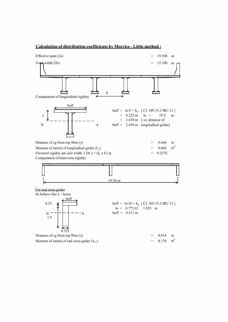
Calculation of distribution coefficients by Morrice - Little method :
Effective span (2a) = 19.500 m
Total width (2b) = 12.100 m
p
Computation of longitudinal rigidity
beff = lo/5 + bw [ Cl. 305.15.2 IRC 21 ]
y = 4.225 m lo = 19.5 m
> 2.650 m [ c/c distance of
beff = 2.650 m longitudinal girder]
Distance of cg from top fibre (y) = 0.666 m
Moment of inertia of longitudinal girder (IL) = 0.602 m4
Flextural rigidity per unit width ( Dx ) = (IL x E) /p = 0.227E
Computation of transverse rigidity
19.50 m
For end cross girder
Its behave like L - beam
beff
0.25 beff = lo/10 + bw [ Cl. 305.15.2 IRC 21 ]
lo = 0.7*2.65 1.855 m
beff = 0.511 m
1.5
0.325
Distance of cg from top fibre (y) = 0.818 m
Moment of inertia of end cross girder (IT1) = 0.170 m4
beff
N A
N A
7/14/2019 RCC T BEAM.xls
http://slidepdf.com/reader/full/rcc-t-beamxls 3/33
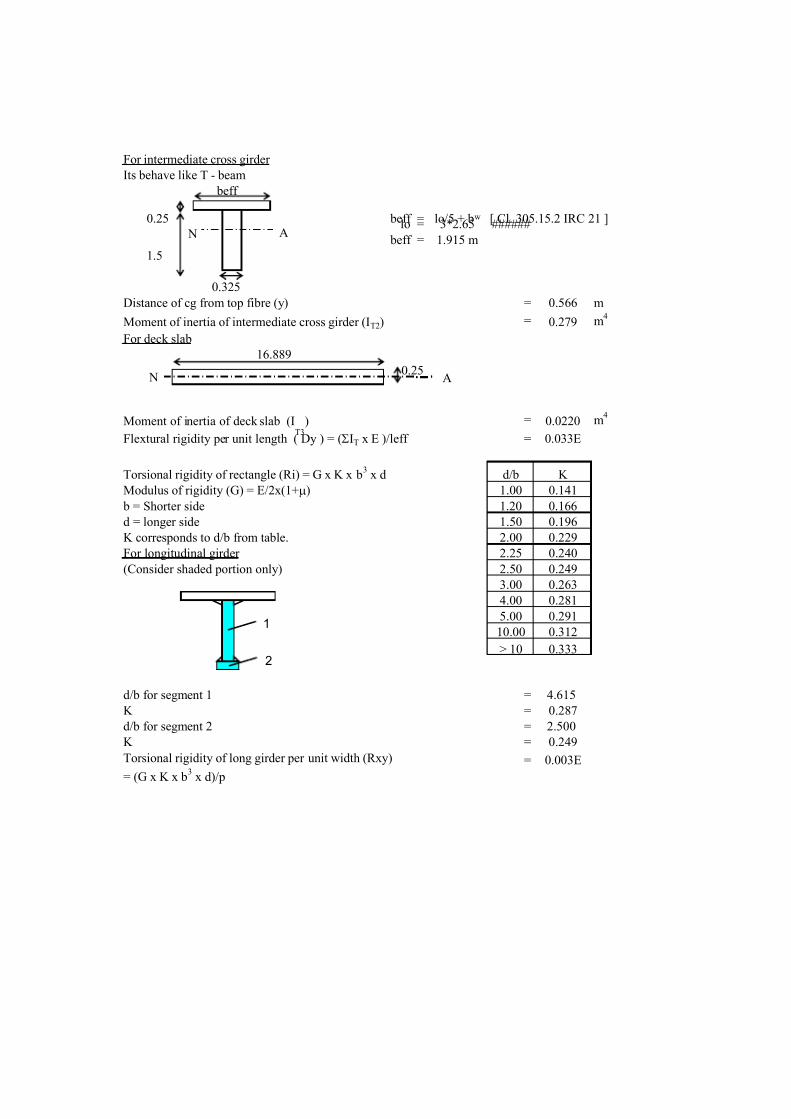
For intermediate cross girder
Its behave like T - beam
beff
0.25 beff = lo/5 + bw [ Cl. 305.15.2 IRC 21 ]lo = 3*2.65 ######
beff = 1.915 m
1.5
0.325
Distance of cg from top fibre (y) = 0.566 m
Moment of inertia of intermediate cross girder (IT2) = 0.279 m4
For deck slab
16.889
0.25
Moment of inertia of deck slab (IT3
) = 0.0220 m4
Flextural rigidity per unit length ( Dy ) = (SIT x E )/leff = 0.033E
Torsional rigidity of rectangle (Ri) = G x K x b3
x d d/b K
Modulus of rigidity (G) = E/2x(1+m) 1.00 0.141
b = Shorter side 1.20 0.166
d = longer side 1.50 0.196
K corresponds to d/b from table. 2.00 0.229
For longitudinal girder 2.25 0.240
(Consider shaded portion only) 2.50 0.249
3.00 0.263
4.00 0.281
5.00 0.291
10.00 0.312
> 10 0.333
d/b for segment 1 = 4.615
K = 0.287
d/b for segment 2 = 2.500
K = 0.249
= 0.003ETorsional rigidity of long girder per unit width (Rxy)
= (G x K x b3
x d)/p
A N
A N
2
1
7/14/2019 RCC T BEAM.xls
http://slidepdf.com/reader/full/rcc-t-beamxls 4/33
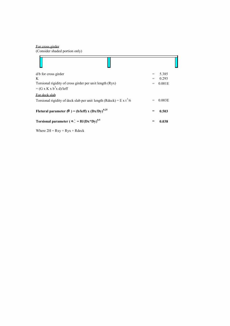
For cross girder
(Consider shaded portion only)
d/b for cross girder = 5.385
K = 0.293
= 0.001E
For deck slab
= 0.003E
Fletural parameter (q ) = (b/leff) x (Dx/Dy)0.25 = 0.503
Torsional parameter ( a ) = H/(Dx*Dy)0.5 = 0.038
Where 2H = Rxy + Ryx + Rdeck
Torsional rigidity of deck slab per unit length (Rdeck) = E x t3/6
Torsional rigidity of cross girder per unit length (Ryx)
= (G x K x b3x d)/leff

7/14/2019 RCC T BEAM.xls
http://slidepdf.com/reader/full/rcc-t-beamxls 5/33
q 0.250
K 0Ref. Pt
Load at
-b -3b/4 -b/2 -b/4 0.000 b/4 b/2 3b/4 b
0.000 0.900 0.970 0.985 1.040 1.080 1.040 0.985 0.970 0.900
b/4 0.220 0.410 0.630 0.850 1.040 1.200 1.350 1.540 1.700
b/2 -0.530 -0.150 0.240 0.630 0.985 1.350 1.720 2.100 2.470
3b/4 -0.170 -0.640 -0.150 -0.410 -0.970 1.540 2.100 2.710 3.280
b -1.850 -1.170 -0.530 -0.220 0.900 1.700 2.470 3.280 4.000
K 1Ref. Pt
Load at-b -3b/4 -b/2 -b/4 0.000 b/4 b/2 3b/4 b
0.000 0.960 0.980 1.000 1.020 1.040 1.020 1.000 0.980 0.960
b/4 0.880 0.910 0.960 0.970 1.020 1.050 1.050 1.050 1.040
b/2 0.810 0.860 0.910 0.960 1.000 1.050 1.100 1.130 1.160
3b/4 0.750 0.800 0.860 0.910 0.980 1.050 1.130 1.220 1.300
b 0.690 0.750 0.810 0.880 0.960 1.040 1.160 1.300 1.460
q 0.275
K 0Ref. Pt
Load at-b -3b/4 -b/2 -b/4 0.000 b/4 b/2 3b/4 b
0.000 0.880 0.960 0.980 1.045 1.090 1.045 0.980 0.960 0.880
b/4 0.210 0.405 0.630 0.860 1.045 1.210 1.355 1.535 1.690
b/2 -0.535 -0.155 0.240 0.630 0.980 1.355 1.725 2.100 2.465
3b/4 -1.160 -0.635 -0.155 0.405 0.960 1.535 2.100 2.720 3.295
b -1.820 -1.160 -0.535 0.210 0.880 1.690 2.465 3.295 4.050
K 1Ref. Pt
Load at-b -3b/4 -b/2 -b/4 0.000 b/4 b/2 3b/4 b
0.000 0.950 0.975 1.000 1.020 1.045 1.020 1.000 0.975 0.950
b/4 0.865 0.900 0.950 0.970 1.020 1.055 1.055 1.050 1.050
b/2 0.790 0.840 0.900 0.950 1.000 1.055 1.115 1.150 1.185
3b/4 0.725 0.775 0.840 0.900 0.975 1.050 1.150 1.255 1.340
b 0.660 0.725 0.790 0.865 0.950 1.050 1.185 1.340 1.525
q 0.300
K 0Ref. Pt
Load at-b -3b/4 -b/2 -b/4 0.000 b/4 b/2 3b/4 b
0.000 0.860 0.950 0.970 1.050 1.100 1.050 0.970 0.950 0.860
b/4 0.200 0.400 0.630 0.870 1.050 1.220 1.360 1.530 1.680
b/2 -0.540 -0.160 0.240 0.630 0.970 1.360 1.730 2.100 2.460
3b/4 -1.150 -0.630 -0.160 0.400 0.950 1.530 2.100 2.730 3.310
b -1.790 -1.150 -0.540 0.200 0.860 1.680 2.460 3.310 4.100

7/14/2019 RCC T BEAM.xls
http://slidepdf.com/reader/full/rcc-t-beamxls 6/33
K 1Ref. Pt
Load at-b -3b/4 -b/2 -b/4 0.000 b/4 b/2 3b/4 b
0.000 0.940 0.970 1.000 1.020 1.050 1.020 1.000 0.970 0.940
b/4 0.850 0.890 0.940 0.970 1.020 1.060 1.060 1.050 1.060
b/2 0.770 0.820 0.890 0.940 1.000 1.060 1.130 1.170 1.210
3b/4 0.700 0.750 0.820 0.890 0.970 1.050 1.170 1.290 1.380
b 0.630 0.700 0.770 0.850 0.940 1.060 1.210 1.380 1.590
q 0.325
K 0Ref. Pt
Load at-b -3b/4 -b/2 -b/4 0.000 b/4 b/2 3b/4 b
0.000 0.830 0.940 0.975 1.065 1.125 1.065 0.975 0.940 0.830
b/4 0.185 0.395 0.630 0.880 1.065 1.235 1.370 1.515 1.650
b/2 -0.540 -0.165 0.240 0.630 0.975 1.370 1.740 2.100 2.445
3b/4 -1.130 -0.615 -0.165 0.395 0.940 1.515 2.100 2.740 3.325
b -1.745 -1.130 -0.540 0.185 0.830 1.650 2.445 3.325 4.150
K 1Ref. Pt
Load at-b -3b/4 -b/2 -b/4 0.000 b/4 b/2 3b/4 b
0.000 0.940 0.965 1.000 1.030 1.055 1.030 1.000 0.965 0.940
b/4 0.830 0.870 0.930 0.970 1.030 1.070 1.070 1.060 1.060
b/2 0.740 0.795 0.870 0.930 1.000 1.070 1.150 1.190 1.230
3b/4 0.675 0.725 0.795 0.870 0.965 1.060 1.190 1.320 1.420
b 0.595 0.675 0.740 0.830 0.940 1.060 1.230 1.420 1.655
q 0.350
K 0Ref. Pt
Load at -b -3b/4 -b/2 -b/4 0.000 b/4 b/2 3b/4 b
0.000 0.800 0.930 0.980 1.080 1.150 1.080 0.980 0.930 0.800
b/4 0.170 0.390 0.630 0.890 1.080 1.250 1.380 1.500 1.620
b/2 -0.545 -0.170 0.240 0.630 0.980 1.380 1.750 2.100 2.430
3b/4 -1.110 -0.600 -0.170 0.390 0.930 1.500 2.100 2.750 3.340
b -1.700 -1.110 -0.545 0.170 0.800 1.620 2.430 3.340 4.200
K 1Ref. Pt
Load at-b -3b/4 -b/2 -b/4 0.000 b/4 b/2 3b/4 b
0.000 0.940 0.960 1.000 1.040 1.060 1.040 1.000 0.960 0.940
b/4 0.810 0.850 0.900 0.970 1.040 1.080 1.080 1.070 1.060
b/2 0.710 0.770 0.850 0.920 1.000 1.080 1.170 1.210 1.250
3b/4 0.650 0.700 0.770 0.850 0.960 1.070 1.210 1.350 1.460
b 0.560 0.650 0.710 0.810 0.940 1.060 1.250 1.460 1.720

7/14/2019 RCC T BEAM.xls
http://slidepdf.com/reader/full/rcc-t-beamxls 7/33
q 0.375
K 0Ref. Pt
Load at
-b -3b/4 -b/2 -b/4 0.000 b/4 b/2 3b/4 b
0.000 0.760 0.900 0.990 1.100 1.180 1.100 0.990 0.900 0.760
b/4 0.150 0.390 0.640 0.860 1.100 1.270 1.380 1.480 1.600
b/2 -0.540 -0.160 0.230 0.640 0.990 1.380 1.750 2.090 2.400
3b/4 -1.090 -0.600 0.160 0.390 0.900 1.480 2.090 2.770 3.360
b -1.670 -1.090 -0.540 0.150 0.760 1.600 2.400 3.360 4.300
K 1Ref. Pt
Load at-b -3b/4 -b/2 -b/4 0.000 b/4 b/2 3b/4 b
0.000 0.910 0.960 1.000 1.040 1.070 1.040 1.000 0.960 0.910
b/4 0.790 0.840 0.910 0.960 1.040 1.100 1.090 1.090 1.070
b/2 0.680 0.750 0.830 0.910 1.000 1.100 1.190 1.240 1.290
3b/4 0.600 0.670 0.750 0.850 0.960 1.090 1.240 1.400 1.520
b 0.520 0.600 0.680 0.790 0.910 1.070 1.290 1.530 1.810
q 0.400
K 0Ref. Pt
Load at-b -3b/4 -b/2 -b/4 0.000 b/4 b/2 3b/4 b
0.000 0.710 0.900 0.990 1.110 1.200 1.110 0.990 0.900 0.710
b/4 0.120 0.360 0.640 0.910 1.110 1.290 1.400 1.470 1.560
b/2 -0.550 -0.170 0.230 0.630 0.990 1.370 1.760 2.100 2.400
3b/4 -1.070 -0.580 -0.170 0.360 0.900 1.470 2.100 2.770 3.380
b -1.650 -1.070 -0.550 0.120 0.710 1.560 2.400 3.380 4.300
K 1Ref. Pt
Load at-b -3b/4 -b/2 -b/4 0.000 b/4 b/2 3b/4 b
0.000 0.900 0.950 1.000 1.050 1.080 1.050 1.000 0.950 0.900
b/4 0.770 0.830 0.900 0.960 1.050 1.100 1.100 1.090 1.070
b/2 0.660 0.730 0.810 0.900 1.000 1.100 1.200 1.260 1.300
3b/4 0.580 0.650 0.730 0.830 0.950 1.090 1.260 1.410 1.550
b 0.500 0.580 0.660 0.770 0.900 1.070 1.300 1.550 1.880
q 0.425
K 0Ref. Pt
Load at-b -3b/4 -b/2 -b/4 0.000 b/4 b/2 3b/4 b
0.000 0.670 0.875 0.995 1.130 1.220 1.130 0.995 0.875 0.670
b/4 0.100 0.350 0.640 0.925 1.130 1.310 1.410 1.455 1.500
b/2 -0.545 -0.170 0.230 0.635 0.995 1.375 1.770 2.095 2.375
3b/4 -1.045 -0.570 -0.170 0.350 0.875 1.455 2.095 2.785 3.405
b -1.600 -1.045 -0.545 0.100 0.670 1.530 2.370 3.405 4.400

7/14/2019 RCC T BEAM.xls
http://slidepdf.com/reader/full/rcc-t-beamxls 8/33
K 1Ref. Pt
Load at-b -3b/4 -b/2 -b/4 0.000 b/4 b/2 3b/4 b
0.000 0.890 0.950 1.000 1.055 1.090 1.055 1.000 0.950 0.890
b/4 0.750 0.810 0.885 0.960 1.055 1.120 1.120 1.095 1.080
b/2 0.630 0.700 0.785 0.885 1.000 1.120 1.225 1.280 1.325
3b/4 0.540 0.615 0.700 0.810 0.950 1.095 1.280 1.455 1.610
b 0.470 0.540 0.630 0.750 0.390 1.080 1.325 1.610 1.940
q 0.450
K 0Ref. Pt
Load at-b -3b/4 -b/2 -b/4 0.000 b/4 b/2 3b/4 b
0.000 0.630 0.850 1.000 1.150 1.250 1.150 1.000 0.850 0.630
b/4 0.080 0.340 0.640 0.940 1.150 1.340 1.420 1.440 1.500
b/2 -0.540 -0.170 0.230 0.640 1.000 1.380 1.780 2.090 2.350
3b/4 -1.020 -0.560 -0.170 0.340 0.850 1.440 2.090 2.800 3.430
b -1.550 -1.020 -0.540 0.080 0.630 1.500 2.350 3.430 4.500
K 1Ref. Pt
Load at-b -3b/4 -b/2 -b/4 0.000 b/4 b/2 3b/4 b
0.000 0.880 0.950 1.000 1.060 1.100 1.060 1.000 0.950 0.880
b/4 0.730 0.790 0.870 0.960 1.060 1.140 1.140 1.100 1.090
b/2 0.600 0.670 0.760 0.870 1.000 1.140 1.250 1.300 1.350
3b/4 0.500 0.580 0.670 0.790 0.950 1.100 1.300 1.500 1.670
b 0.440 0.500 0.600 0.730 0.880 1.090 1.350 1.670 2.000
q 0.475
K 0Ref. Pt
Load at-b -3b/4 -b/2 -b/4 0.000 b/4 b/2 3b/4 b
0.000 0.590 0.820 1.000 1.180 1.285 1.180 1.000 0.820 0.590
b/4 0.040 0.320 0.635 0.950 1.180 1.370 1.430 1.420 1.450
b/2 -0.540 -0.170 0.225 0.635 1.000 1.390 1.790 2.085 2.325
3b/4 -0.990 -0.550 -0.170 0.320 0.820 1.420 2.085 2.820 3.465
b -1.490 -0.990 -0.540 0.040 0.590 1.450 2.325 3.465 4.650
K 1Ref. Pt
Load at-b -3b/4 -b/2 -b/4 0.000 b/4 b/2 3b/4 b
0.000 0.865 0.935 1.000 1.065 1.115 1.065 1.000 0.935 0.865
b/4 0.705 0.775 0.865 0.960 1.065 1.150 1.145 1.110 1.090
b/2 0.575 0.650 0.745 0.865 1.000 1.145 1.275 1.325 1.370
3b/4 0.475 0.555 0.650 0.775 0.935 1.110 1.325 1.540 1.715
b 0.410 0.475 0.575 0.705 0.865 1.090 1.370 1.715 1.075

7/14/2019 RCC T BEAM.xls
http://slidepdf.com/reader/full/rcc-t-beamxls 9/33
q 0.500
K 0Ref. Pt
Load at
-b -3b/4 -b/2 -b/4 0.000 b/4 b/2 3b/4 b
0.000 0.550 0.790 1.000 1.210 1.320 1.210 1.000 0.790 0.550
b/4 0.000 0.300 0.630 0.960 1.210 1.400 1.440 1.400 1.400
b/2 -0.540 -0.170 0.220 0.630 1.000 1.400 1.800 2.080 2.300
3b/4 -0.960 -0.540 -0.170 0.300 0.790 1.400 2.080 2.840 3.500
b -1.430 -0.960 -0.540 0.000 0.550 1.400 2.300 3.500 4.800
K 1Ref. Pt
Load at-b -3b/4 -b/2 -b/4 0.000 b/4 b/2 3b/4 b
0.000 0.850 0.920 1.000 1.070 1.130 1.070 1.000 0.920 0.850
b/4 0.680 0.760 0.860 0.960 1.070 1.160 1.150 1.120 1.090
b/2 0.550 0.630 0.730 0.860 1.000 1.150 1.300 1.350 1.390
3b/4 0.450 0.530 0.630 0.760 0.920 1.120 1.350 1.580 1.760
b 0.380 0.450 0.550 0.680 0.850 1.090 1.390 1.760 2.150
q 0.525
K 0Ref. Pt
Load at-b -3b/4 -b/2 -b/4 0.000 b/4 b/2 3b/4 b
0.000 0.485 0.765 1.010 1.240 1.360 1.240 1.010 0.765 0.485
b/4 -0.050 0.275 0.630 0.970 1.240 1.425 1.450 1.375 1.330
b/2 -0.535 -0.175 0.215 0.630 1.010 1.415 1.820 2.075 2.275
3b/4 -0.925 -0.520 -0.175 0.275 0.765 1.375 2.075 2.855 3.600
b -1.365 -0.925 -0.535 -0.050 0.485 1.330 2.275 3.600 4.950
K 1Ref. Pt
Load at-b -3b/4 -b/2 -b/4 0.000 b/4 b/2 3b/4 b
0.000 0.830 0.910 1.000 1.080 1.140 1.080 1.000 0.910 0.830
b/4 0.665 0.735 0.850 0.960 1.080 1.170 1.160 1.130 1.090
b/2 0.525 0.605 0.710 0.850 1.000 1.160 1.325 1.375 1.415
3b/4 0.425 0.505 0.605 0.735 0.910 1.130 1.375 1.615 1.815
b 0.355 0.425 0.525 0.665 0.830 1.090 1.415 1.815 2.240
q 0.550
K 0Ref. Pt
Load at-b -3b/4 -b/2 -b/4 0.000 b/4 b/2 3b/4 b
0.000 0.420 0.740 1.020 1.270 1.400 1.270 1.020 0.740 0.420
b/4 -0.100 0.250 0.630 0.980 1.270 1.450 1.460 1.350 1.260
b/2 -0.530 -0.180 0.210 0.630 1.020 1.430 1.840 2.070 2.250
3b/4 -0.890 -0.500 -0.180 0.250 0.740 1.350 2.070 2.870 3.700
b -1.300 -0.890 -0.530 -0.100 0.420 1.260 2.250 3.700 5.100

7/14/2019 RCC T BEAM.xls
http://slidepdf.com/reader/full/rcc-t-beamxls 10/33
K 1Ref. Pt
Load at-b -3b/4 -b/2 -b/4 0.000 b/4 b/2 3b/4 b
0.000 0.810 0.900 1.000 1.090 1.150 1.090 1.000 0.900 0.810
b/4 0.650 0.710 0.840 0.960 1.090 1.180 1.170 1.140 1.090
b/2 0.500 0.580 0.690 0.840 1.000 1.170 1.350 1.400 1.440
3b/4 0.400 0.480 0.580 0.710 0.900 1.140 1.400 1.650 1.870
b 0.330 0.400 0.500 0.650 0.810 1.090 1.440 1.870 2.330
q 0.575
K 0Ref. Pt
Load at-b -3b/4 -b/2 -b/4 0.000 b/4 b/2 3b/4 b
0.000 0.350 0.700 1.020 1.330 1.460 1.330 1.020 0.700 0.350
b/4 -0.130 0.220 0.620 1.000 1.330 1.500 1.480 1.340 1.100
b/2 -0.530 -0.180 0.210 0.620 1.020 1.480 1.860 2.080 2.260
3b/4 -0.840 -0.490 -0.180 0.220 0.700 1.340 2.080 2.900 3.800
b -1.160 -0.840 0.530 0.130 0.350 1.100 2.220 3.800 5.300
K 1Ref. Pt
Load at-b -3b/4 -b/2 -b/4 0.000 b/4 b/2 3b/4 b
0.000 0.800 0.890 1.000 1.110 1.170 1.110 1.000 0.890 0.800
b/4 0.600 0.700 0.810 0.950 1.110 1.210 1.200 1.140 1.080
b/2 0.470 0.550 0.660 0.810 1.000 1.200 1.380 1.440 1.450
3b/4 0.370 0.450 0.550 0.700 0.890 1.140 1.440 1.720 1.920
b 0.300 0.370 0.470 0.600 0.800 1.080 1.450 1.920 2.420
q 0.600
K 0Ref. Pt
Load at-b -3b/4 -b/2 -b/4 0.000 b/4 b/2 3b/4 b
0.000 0.310 0.660 1.020 1.350 1.500 1.350 1.020 0.660 0.310
b/4 -0.170 0.210 0.620 1.020 1.350 1.530 1.470 1.310 1.030
b/2 -0.520 -0.180 0.200 0.620 1.020 1.470 1.870 2.060 2.190
3b/4 -0.800 -0.470 -0.180 0.210 0.660 1.310 2.060 2.920 3.080
b -1.050 -0.800 -0.520 -0.200 0.310 1.100 2.190 3.080 5.450
.
K 1Ref. Pt
Load at-b -3b/4 -b/2 -b/4 0.000 b/4 b/2 3b/4 b
0.000 0.800 0.890 1.000 1.120 1.190 1.120 1.000 0.890 0.800
b/4 0.580 0.670 0.800 0.950 1.120 1.230 1.200 1.150 1.080
b/2 0.440 0.520 0.660 0.800 1.000 1.200 1.400 1.450 1.460
3b/4 0.340 0.410 0.520 0.670 0.890 1.150 1.450 1.750 1.960
b 0.280 0.340 0.440 0.580 0.800 1.080 1.460 1.960 2.500

7/14/2019 RCC T BEAM.xls
http://slidepdf.com/reader/full/rcc-t-beamxls 11/33
q 0.625
K 0Ref. Pt
Load at
-b -3b/4 -b/2 -b/4 0.000 b/4 b/2 3b/4 b
0.000 0.230 0.635 1.023 1.390 1.540 1.390 1.023 0.630 0.230
b/4 -0.220 0.180 0.615 1.030 1.390 1.570 1.490 1.290 0.965
b/2 -0.520 -0.180 0.200 0.615 1.023 1.490 1.890 2.060 2.160
3b/4 -0.755 -0.455 -0.180 0.180 0.635 1.290 2.060 2.935 3.045
b -0.920 -0.755 -0.520 -0.235 0.230 1.010 2.160 3.045 5.250
.
K 1Ref. Pt
Load at-b -3b/4 -b/2 -b/4 0.000 b/4 b/2 3b/4 b
0.000 0.775 0.870 0.990 1.013 1.210 1.130 0.990 0.870 0.775
b/4 0.515 0.655 0.785 0.950 1.130 1.250 1.220 1.150 1.070
b/2 0.420 0.495 0.615 0.785 0.990 1.220 1.425 1.480 1.480
3b/4 0.320 0.385 0.495 0.655 0.870 1.150 1.480 1.845 2.010
b 0.260 0.320 0.420 0.555 0.775 1.070 1.480 2.010 2.775
q 0.650
K 0Ref. Pt
Load at-b -3b/4 -b/2 -b/4 0.000 b/4 b/2 3b/4 b
0.000 0.150 0.610 1.025 1.420 1.580 1.420 1.025 0.610 0.150
b/4 -0.260 0.150 0.610 1.040 1.420 1.600 1.510 1.260 0.900
b/2 -0.520 -0.180 0.200 0.610 1.025 1.510 1.910 2.060 2.130
3b/4 -0.710 -0.440 -0.180 -0.150 0.610 1.260 2.060 2.950 3.010
b -0.800 -0.710 -0.520 -0.270 0.150 0.920 2.130 3.010 5.070
.
K 1Ref. Pt
Load at-b -3b/4 -b/2 -b/4 0.000 b/4 b/2 3b/4 b
0.000 0.750 0.850 0.980 1.140 0.980 0.850 0.750 0.870 0.775
b/4 0.550 0.640 0.770 0.950 1.140 1.270 1.240 1.150 1.060
b/2 0.400 0.470 0.600 0.770 0.980 1.240 1.450 1.500 1.500
3b/4 0.300 0.360 0.470 0.640 0.850 1.150 1.500 1.840 2.060
b 0.240 0.300 0.400 0.530 0.750 1.060 1.500 2.060 2.650
q 0.675
K 0Ref. Pt
Load at-b -3b/4 -b/2 -b/4 0.000 b/4 b/2 3b/4 b
0.000 0.055 0.570 1.027 1.470 1.630 1.465 1.027 0.570 0.055
b/4 -0.315 0.130 0.605 1.050 1.470 1.650 1.530 1.235 0.785
b/2 -0.510 -0.185 0.190 0.605 1.027 1.530 1.935 2.055 2.080
3b/4 -0.640 -0.420 -0.185 0.130 0.570 1.235 2.055 2.975 3.150
b -0.640 -0.640 -0.510 -0.320 0.055 0.825 2.080 3.510 5.500.

7/14/2019 RCC T BEAM.xls
http://slidepdf.com/reader/full/rcc-t-beamxls 12/33
K 1Ref. Pt
Load at-b -3b/4 -b/2 -b/4 0.000 b/4 b/2 3b/4 b
0.000 0.730 0.842 0.980 1.155 1.255 1.155 0.980 0.842 0.730
b/4 0.525 0.615 0.755 0.945 1.155 1.300 1.250 1.150 1.050
b/2 0.365 0.450 0.575 0.755 0.980 1.250 1.480 1.525 1.510
3b/4 0.270 0.370 0.450 0.615 0.842 1.150 1.525 1.385 2.110
b 0.200 0.270 0.365 0.510 0.730 1.050 1.510 2.110 2.750
q 0.700
K 0Ref. Pt
Load at-b -3b/4 -b/2 -b/4 0.000 b/4 b/2 3b/4 b
0.000 -0.040 0.530 1.030 1.520 1.680 1.510 1.030 0.530 -0.040
b/4 -0.370 0.110 0.000 1.060 1.510 1.700 1.550 1.210 0.670
b/2 -0.500 -0.190 0.180 0.600 1.030 1.550 1.960 2.050 2.030
3b/4 -0.570 -0.400 -0.190 0.110 0.530 1.210 2.050 3.000 4.010
b -0.480 -0.570 -0.500 -0.370 -0.040 0.730 2.030 4.010 6.030
.
K 1Ref. Pt
Load at-b -3b/4 -b/2 -b/4 0.000 b/4 b/2 3b/4 b
0.000 0.710 0.835 0.980 1.170 1.280 1.170 0.980 0.835 0.710
b/4 0.500 0.590 0.740 0.940 1.170 1.330 1.270 1.150 1.040
b/2 0.330 0.430 0.550 0.740 0.980 1.270 1.510 1.550 1.520
3b/4 0.240 0.320 0.430 0.590 0.835 1.150 1.550 1.930 2.160
b 0.180 0.240 0.330 0.490 0.710 1.040 1.520 2.160 2.850
q 0.725
K 0Ref. Pt
Load at-b -3b/4 -b/2 -b/4 0.000 b/4 b/2 3b/4 b
0.000 -0.125 0.495 1.025 1.550 1.725 1.550 1.025 0.495 -0.125
b/4 -0.400 0.080 0.585 1.070 1.550 1.735 1.570 1.180 0.585
b/2 -0.495 -0.185 0.175 0.585 1.025 1.570 1.980 2.040 1.990
3b/4 -0.505 -0.375 -0.185 0.080 0.495 1.180 2.040 3.025 3.600
b -0.390 -0.505 -0.495 -0.400 0.125 0.645 1.990 3.600 6.365
.
K 1Ref. Pt
Load at-b -3b/4 -b/2 -b/4 0.000 b/4 b/2 3b/4 b
0.000 0.685 0.817 0.980 1.185 1.305 1.185 0.980 0.817 0.685
b/4 0.475 0.570 0.730 0.940 1.185 1.350 1.285 1.150 1.030
b/2 0.315 0.410 0.530 0.730 0.980 1.285 1.540 1.575 1.535
3b/4 0.225 0.300 0.410 0.570 0.817 1.150 1.575 1.920 2.205
b 0.165 0.225 0.315 0.470 0.685 1.030 1.535 2.205 2.925
7/14/2019 RCC T BEAM.xls
http://slidepdf.com/reader/full/rcc-t-beamxls 13/33
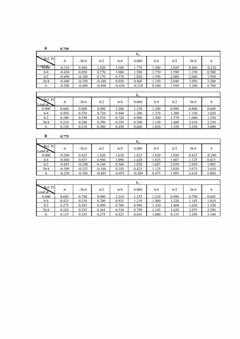
q 0.750
K 0Ref. Pt
Load at
-b -3b/4 -b/2 -b/4 0.000 b/4 b/2 3b/4 b
0.000 -0.210 0.460 1.020 1.580 1.770 1.580 1.020 0.460 -0.210
b/4 -0.430 0.050 0.570 1.080 1.580 1.770 1.590 1.150 0.500
b/2 -0.490 -0.180 0.170 0.570 1.020 1.590 2.000 2.040 1.950
3b/4 -0.440 -0.350 -0.180 0.050 0.460 1.150 2.040 3.050 3.200
b -0.300 -0.440 -0.490 -0.430 -0.210 0.560 1.950 3.200 6.700
.
K 1Ref. Pt
Load at-b -3b/4 -b/2 -b/4 0.000 b/4 b/2 3b/4 b
0.000 0.660 0.800 0.980 1.200 1.330 1.200 0.980 0.800 0.660
b/4 0.450 0.550 0.720 0.940 1.200 1.370 1.300 1.150 1.020
b/2 0.300 0.390 0.510 0.720 0.980 1.300 1.570 1.600 1.550
3b/4 0.210 0.280 0.390 0.550 0.500 1.150 1.600 2.010 2.250
b 0.150 0.210 0.300 0.450 0.660 1.020 1.550 2.250 3.000
q 0.775
K 0Ref. Pt
Load at-b -3b/4 -b/2 -b/4 0.000 b/4 b/2 3b/4 b
0.000 -0.280 0.425 1.020 1.620 1.825 1.620 1.020 0.425 -0.280
b/4 -0.460 0.035 0.560 1.090 1.620 1.825 1.607 1.125 0.415
b/2 -0.485 -0.180 0.160 0.560 1.020 1.607 2.030 2.030 1.885
3b/4 -0.390 -0.325 -0.180 0.350 0.425 1.125 2.030 3.075 3.610
b -0.230 -0.390 -0.485 -0.455 -0.280 0.475 1.885 3.610 6.860
.
K 1Ref. Pt
Load at-b -3b/4 -b/2 -b/4 0.000 b/4 b/2 3b/4 b
0.000 0.645 0.790 0.980 1.210 1.355 1.210 0.980 0.790 0.645
b/4 0.425 0.530 0.700 0.935 1.210 1.400 1.320 1.145 1.010
b/2 0.275 0.365 0.490 0.700 0.980 1.320 1.600 1.620 1.550
3b/4 0.185 0.255 0.365 0.530 0.790 1.145 1.620 2.055 2.290
b 0.135 0.185 0.275 0.425 0.645 1.000 0.155 2.290 3.100
7/14/2019 RCC T BEAM.xls
http://slidepdf.com/reader/full/rcc-t-beamxls 14/33
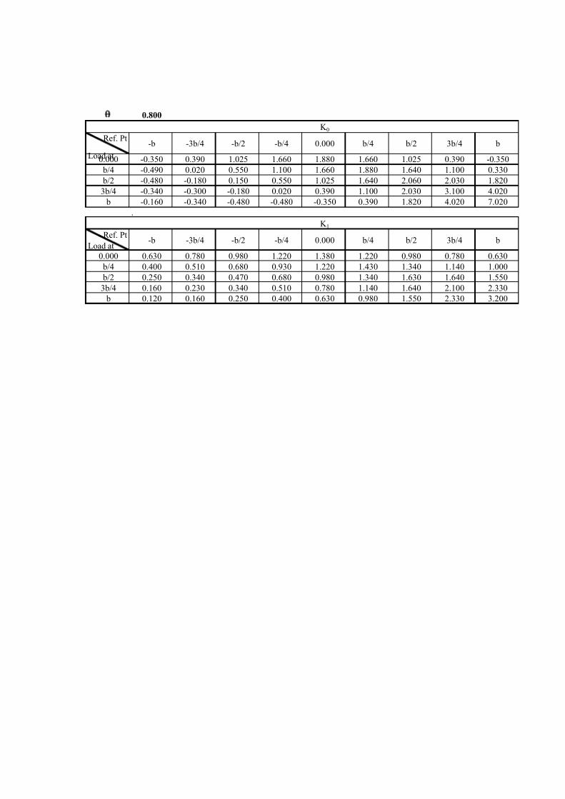
q 0.800
K 0Ref. Pt
Load at
-b -3b/4 -b/2 -b/4 0.000 b/4 b/2 3b/4 b
0.000 -0.350 0.390 1.025 1.660 1.880 1.660 1.025 0.390 -0.350
b/4 -0.490 0.020 0.550 1.100 1.660 1.880 1.640 1.100 0.330
b/2 -0.480 -0.180 0.150 0.550 1.025 1.640 2.060 2.030 1.820
3b/4 -0.340 -0.300 -0.180 0.020 0.390 1.100 2.030 3.100 4.020
b -0.160 -0.340 -0.480 -0.480 -0.350 0.390 1.820 4.020 7.020
.
K 1Ref. Pt
Load at-b -3b/4 -b/2 -b/4 0.000 b/4 b/2 3b/4 b
0.000 0.630 0.780 0.980 1.220 1.380 1.220 0.980 0.780 0.630
b/4 0.400 0.510 0.680 0.930 1.220 1.430 1.340 1.140 1.000
b/2 0.250 0.340 0.470 0.680 0.980 1.340 1.630 1.640 1.550
3b/4 0.160 0.230 0.340 0.510 0.780 1.140 1.640 2.100 2.330
b 0.120 0.160 0.250 0.400 0.630 0.980 1.550 2.330 3.200

7/14/2019 RCC T BEAM.xls
http://slidepdf.com/reader/full/rcc-t-beamxls 15/33
Unit load distribution coefficient.
q 0.503
For no torsion grillage a = 0 K 0
Ref. PtLoad at
-b -3b/4 -b/2 -b/4 0 b/4 b/2 3b/4 b
0 0.541 0.787 1.001 1.214 1.325 1.214 1.001 0.787 0.541 7.87
b/4 -0.007 0.297 0.630 0.961 1.214 1.403 1.441 1.397 1.391 8.04
b/2 -0.539 -0.171 0.219 0.630 1.001 1.402 1.803 2.079 2.297 7.84
3b/4 -0.955 -0.537 -0.171 0.297 0.787 1.397 2.079 2.842 3.513 7.97
b -1.421 -0.955 -0.539 -0.007 0.541 1.391 2.297 3.513 4.820 7.94
For full torsion grillage a = 1 K 1Ref. Pt
Load at-b -3b/4 -b/2 -b/4 0 b/4 b/2 3b/4 b
0 0.847 0.919 1.000 1.071 1.131 1.071 1.000 0.919 0.847 7.96
b/4 0.678 0.757 0.859 0.960 1.071 1.161 1.151 1.121 1.090 7.96
b/2 0.547 0.627 0.727 0.859 1.000 1.151 1.303 1.353 1.393 7.99
3b/4 0.447 0.527 0.627 0.757 0.919 1.121 1.353 1.585 1.767 8.00 b 0.377 0.447 0.547 0.678 0.847 1.090 1.393 1.767 2.162 8.04
K a= K 0+(K 1-K 0)x(a)0.5
Ref. Pt
Load at-b -3b/4 -b/2 -b/4 0 b/4 b/2 3b/4 b
-b 4.300 3.172 2.120 1.332 0.601 0.127 -0.327 -0.681 -1.070 7.96
-3b/4 3.172 2.596 1.937 1.343 0.812 0.387 -0.015 -0.329 -0.681 7.98
-b/2 2.120 1.937 1.705 1.353 1.001 0.675 0.319 -0.015 -0.327 7.87
-b/4 1.332 1.343 1.385 1.356 1.186 0.961 0.675 0.387 0.127 8.02
0 0.601 0.812 1.001 1.186 1.287 1.186 1.001 0.812 0.601 7.89
b/4 0.127 0.387 0.675 0.961 1.186 1.356 1.385 1.343 1.332 8.02
b/2 -0.327 -0.015 0.319 0.675 1.001 1.353 1.705 1.937 2.120 7.87
3b/4 -0.681 -0.329 -0.015 0.387 0.812 1.343 1.937 2.596 3.172 7.98
b -1.070 -0.681 -0.327 0.127 0.601 1.332 2.120 3.172 4.300 7.96
Rowintegral
Row
integral
Row
integral
RUN

7/14/2019 RCC T BEAM.xls
http://slidepdf.com/reader/full/rcc-t-beamxls 16/33
Distribution coefficient K' for SIDL
0.5 t/m 0.5 t/m
2.075 2.650 2.65 2.65 2.075
lwK a
Ref. Pt
Load at
oa
factor
(lw )
-b -3b/4 -b/2 -b/4 0 b/4 b/2 3b/4 b
-b 0.43 1.87 1.38 0.92 0.58 0.26 0.06 -0.14 -0.30 -0.46
-3b/4 0.07 0.21 0.17 0.13 0.09 0.05 0.03 0.00 -0.02 -0.05
-b/2 0.00 0.00 0.00 0.00 0.00 0.00 0.00 0.00 0.00 0.00
-b/4 0.00 0.00 0.00 0.00 0.00 0.00 0.00 0.00 0.00 0.00
0 0.00 0.00 0.00 0.00 0.00 0.00 0.00 0.00 0.00 0.00
b/4 0.00 0.00 0.00 0.00 0.00 0.00 0.00 0.00 0.00 0.00
b/2 0.00 0.00 0.00 0.00 0.00 0.00 0.00 0.00 0.00 0.00
3b/4 0.07 -0.05 -0.02 0.00 0.03 0.05 0.09 0.13 0.17 0.21
b 0.43 -0.46 -0.30 -0.14 0.06 0.26 0.58 0.92 1.38 1.87
Slw 1.00
SlwK a 1.57 1.23 0.91 0.75 0.63 0.75 0.91 1.23 1.57
1.566 1.231 0.905 0.747 0.629 0.747 0.905 1.231 1.566
Distribution coefficient K' at girder location
Girder Nr. G1 G2 G3 G4
K' 1.221 0.806 0.774 1.221
Note : Coefficients have been increased by 10% to take into account the effect of higher harmonics.
K ' = SlwK a/Slw
G1 G2 G3 G4
-b -3b/4 -b/2 -b/4 0 b/4 b/2 3b/4 b

7/14/2019 RCC T BEAM.xls
http://slidepdf.com/reader/full/rcc-t-beamxls 17/33
Distribution coefficient K' for live load (3 lane class A)
2.075 2.65 2.65 2.65 2.075
lwK a
Ref. Pt
Load at
Load
factor
(lw )
-b -3b/4 -b/2 -b/4 0 b/4 b/2 3b/4 b
-b 2.12 9.11 6.72 4.49 2.82 1.27 0.27 -0.69 -1.44 -2.27
-3b/4 4.62 14.65 11.99 8.95 6.20 3.75 1.79 -0.07 -1.52 -3.15
-b/2 4.99 10.58 9.67 8.51 6.75 5.00 3.37 1.59 -0.07 -1.63
-b/4 5.37 7.15 7.21 7.44 7.28 6.37 5.16 3.62 2.08 0.68
0 4.95 2.97 4.02 4.95 5.87 6.37 5.87 4.95 4.02 2.97
b/4 4.99 0.63 1.93 3.37 4.80 5.92 6.77 6.91 6.70 6.65
b/2 4.62 -1.51 -0.07 1.47 3.12 4.62 6.25 7.87 8.95 9.79
3b/4 2.54 -1.73 -0.84 -0.04 0.98 2.07 3.42 4.93 6.60 8.07
b 0.00 0.00 0.00 0.00 0.00 0.00 0.00 0.00 0.00 0.00
Slw 34.20
SlwK a 41.86 40.64 39.14 37.82 35.37 32.88 29.12 25.31 21.12
1.224 1.188 1.145 1.106 1.034 0.962 0.851 0.740 0.617
Distribution coefficient K' at girder location
Girder Nr. G1 G2 G3 G4K' 1.289 1.207 1.087 0.860
Note : Coefficients have been increased by 10% to take into account the effect of higher harmonics.
K ' = SlwK a/Slw
G1 G2 G3 G4
-b -3b/4 -b/2 -b/4 0 b/4 b/2 3b/4 b
Class A
1.8m0.95m
Class A
1.8m1.7m
Class A
1.8m1.7m
7/14/2019 RCC T BEAM.xls
http://slidepdf.com/reader/full/rcc-t-beamxls 18/33
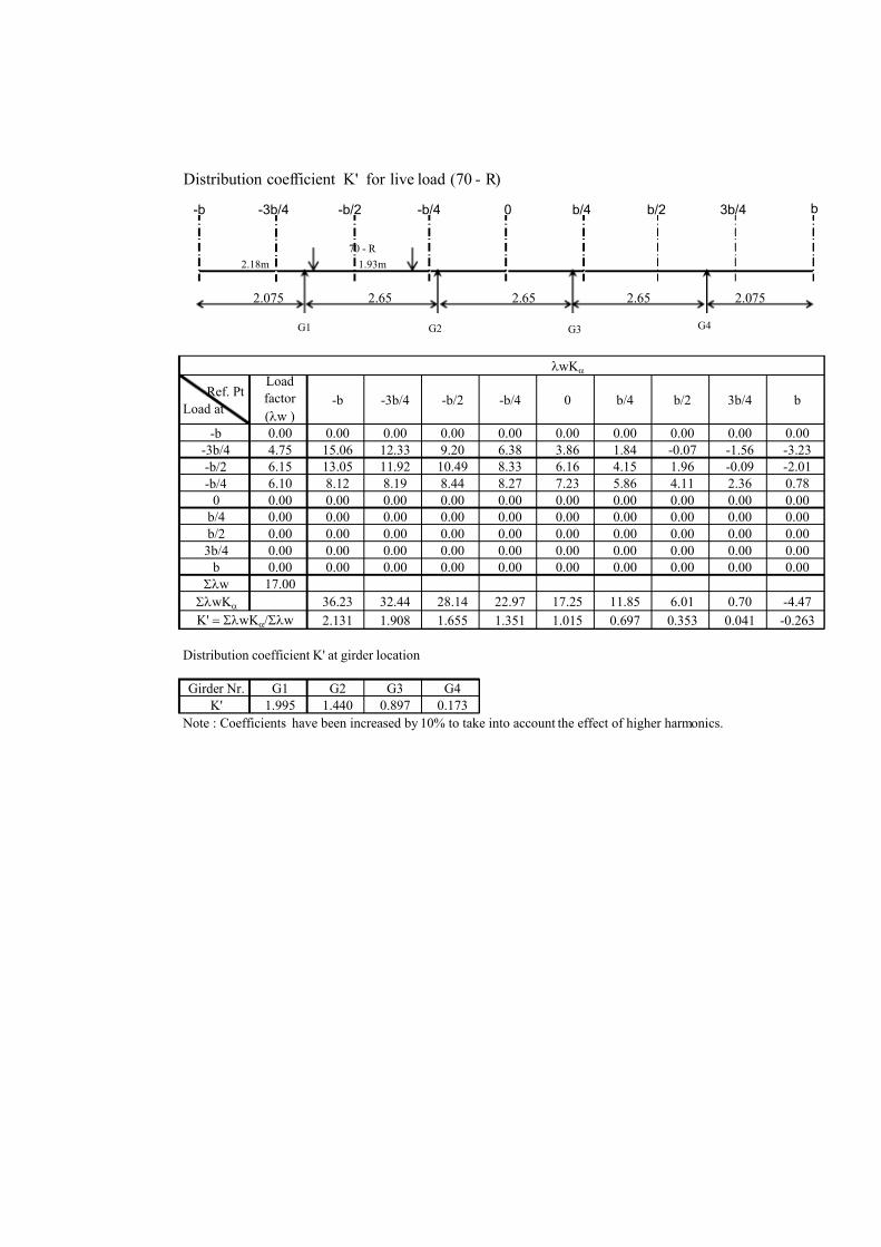
Distribution coefficient K' for live load (70 - R)
2.075 2.65 2.65 2.65 2.075
lwK a
Ref. Pt
Load at
Load
factor
(lw )
-b -3b/4 -b/2 -b/4 0 b/4 b/2 3b/4 b
-b 0.00 0.00 0.00 0.00 0.00 0.00 0.00 0.00 0.00 0.00
-3b/4 4.75 15.06 12.33 9.20 6.38 3.86 1.84 -0.07 -1.56 -3.23
-b/2 6.15 13.05 11.92 10.49 8.33 6.16 4.15 1.96 -0.09 -2.01
-b/4 6.10 8.12 8.19 8.44 8.27 7.23 5.86 4.11 2.36 0.78
0 0.00 0.00 0.00 0.00 0.00 0.00 0.00 0.00 0.00 0.00
b/4 0.00 0.00 0.00 0.00 0.00 0.00 0.00 0.00 0.00 0.00
b/2 0.00 0.00 0.00 0.00 0.00 0.00 0.00 0.00 0.00 0.00
3b/4 0.00 0.00 0.00 0.00 0.00 0.00 0.00 0.00 0.00 0.00
b 0.00 0.00 0.00 0.00 0.00 0.00 0.00 0.00 0.00 0.00
Slw 17.00
SlwK a 36.23 32.44 28.14 22.97 17.25 11.85 6.01 0.70 -4.47
2.131 1.908 1.655 1.351 1.015 0.697 0.353 0.041 -0.263
Distribution coefficient K' at girder location
Girder Nr. G1 G2 G3 G4
K' 1.995 1.440 0.897 0.173
Note : Coefficients have been increased by 10% to take into account the effect of higher harmonics.
K ' = SlwK a/Slw
70 - R
1.93m2.18m
G1 G2 G3 G4
-b -3b/4 -b/2 -b/4 0 b/4 b/2 3b/4 b

7/14/2019 RCC T BEAM.xls
http://slidepdf.com/reader/full/rcc-t-beamxls 19/33
Distribution coefficient K' for live load (1lane class A + 70 - R)
2.075 2.65 2.65 2.65 2.075
lwK a
Ref. Pt
Load at
Load
factor
(lw )
-b -3b/4 -b/2 -b/4 0 b/4 b/2 3b/4 b
-b 0.00 0.00 0.00 0.00 0.00 0.00 0.00 0.00 0.00 0.00
-3b/4 4.75 15.07 12.33 9.20 6.38 3.86 1.84 -0.07 -1.56 -3.24
-b/2 6.15 13.04 11.91 10.49 8.32 6.16 4.15 1.96 -0.09 -2.01
-b/4 6.33 8.43 8.50 8.76 8.58 7.51 6.08 4.27 2.45 0.80
0 5.47 3.29 4.44 5.48 6.49 7.04 6.49 5.48 4.44 3.29
b/4 4.84 0.62 1.87 3.27 4.65 5.74 6.56 6.70 6.50 6.45
b/2 0.86 -0.28 -0.01 0.27 0.58 0.86 1.16 1.47 1.67 1.82
3b/4 0.00 0.00 0.00 0.00 0.00 0.00 0.00 0.00 0.00 0.00
b 0.00 0.00 0.00 0.00 0.00 0.00 0.00 0.00 0.00 0.00
Slw 28.40
SlwK a 40.16 39.05 37.47 35.00 31.17 26.28 19.80 13.40 7.12
1.414 1.375 1.319 1.233 1.097 0.926 0.697 0.472 0.251
Distribution coefficient K' at girder location
Girder Nr. G1 G2 G3 G4
K' 1.490 1.337 1.088 0.611
Note : Coefficients have been increased by 10% to take into account the effect of higher harmonics.
K ' = SlwK a/Slw
70 - R
1.93m2.18m
Class A
1.8m
G1 G2 G3 G4
-b -3b/4 -b/2 -b/4 0 b/4 b/2 3b/4 b
7/14/2019 RCC T BEAM.xls
http://slidepdf.com/reader/full/rcc-t-beamxls 20/33
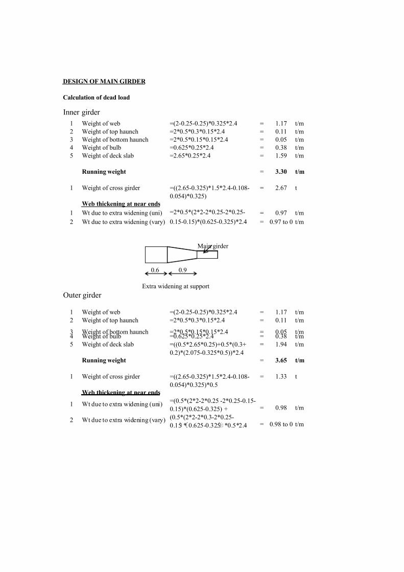
DESIGN OF MAIN GIRDER
Calculation of dead load
Inner girder
1 Weight of web =(2-0.25-0.25)*0.325*2.4 = 1.17 t/m
2 Weight of top haunch =2*0.5*0.3*0.15*2.4 = 0.11 t/m
3 Weight of bottom haunch =2*0.5*0.15*0.15*2.4 = 0.05 t/m
4 Weight of bulb =0.625*0.25*2.4 = 0.38 t/m
5 Weight of deck slab =2.65*0.25*2.4 = 1.59 t/m
Running weight = 3.30 t/m
1 Weight of cross girder = 2.67 t
Web thickening at near ends
1 Wt due to extra widening (uni) = 0.97 t/m
2 Wt due to extra widening (vary) = 0.97 to 0 t/m
Main girder
0.6 0.9
Extra widening at support
Outer girder
1 Weight of web =(2-0.25-0.25)*0.325*2.4 = 1.17 t/m
2 Weight of top haunch =2*0.5*0.3*0.15*2.4 = 0.11 t/m
3 Weight of bottom haunch =2*0.5*0.15*0.15*2.4 = 0.05 t/m4 Weight of bulb =0.625*0.25*2.4 = 0.38 t/m
5 Weight of deck slab = 1.94 t/m
Running weight = 3.65 t/m
1 Weight of cross girder = 1.33 t
Web thickening at near ends
1 Wt due to extra widening (uni)= 0.98 t/m
2 Wt due to extra widening (vary)= 0.98 to 0 t/m
=2*0.5*(2*2-2*0.25-2*0.25-
0.15-0.15)*(0.625-0.325)*2.4
=((2.65-0.325)*1.5*2.4-0.108-
0.054)*0.325)*0.5
=(0.5*(2*2-2*0.25 -2*0.25-0.15-
0.15)*(0.625-0.325) +
(0.5*(2*2-2*0.3-2*0.25-
0.15 * 0.625-0.325 *0.5*2.4
=((0.5*2.65*0.25)+0.5*(0.3+
0.2)*(2.075-0.325*0.5))*2.4
=((2.65-0.325)*1.5*2.4-0.108-
0.054)*0.325)

7/14/2019 RCC T BEAM.xls
http://slidepdf.com/reader/full/rcc-t-beamxls 21/33
Calculation of SIDL (uniform)
Inner girder 1 Weight of wearing coat = 0.53 t/m
Outer girder 1 Weight of wearing coat = 0.57 t/m
Calculation of SIDL (concentrated)
2 Weight of crash barrier = 2.00 t/m
Total concentrated SIDL = 2.00 t/m
Calculation of bending moment and shear force (DL+SIDL)
(Uniform SIDL like wearing coat)
Inner girder
2.67 t 2.67 t 2.67 t
9.75 9.75
3.83t/m 0.97t/m
0.9 0.6
19.5 m
A B
Support reaction at A = 42.34 t
Deff
from sup
Span
(L/8)
Span
(L/4)
Span
(L/2)
1 BM (t-m) 70.2 83.4 143.5 195.5
2 SF (t) 31.0 29.3 20.0 0.0
Outer girder
1.33 t 1.33 t 1.33 t
9.75 9.75
4.22t/m 0.98t/m
0.9 0.6
19.5 m
A B
Location
Sl. Nr. Item
7/14/2019 RCC T BEAM.xls
http://slidepdf.com/reader/full/rcc-t-beamxls 22/33
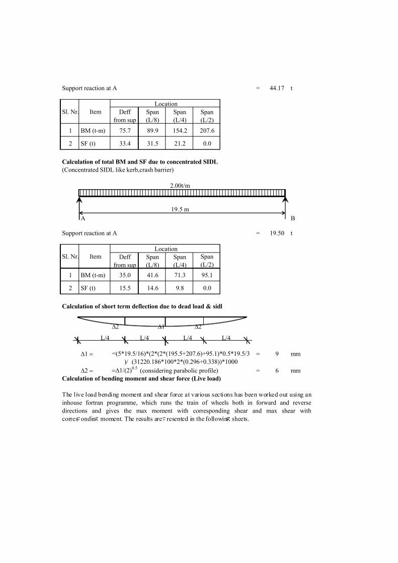
Support reaction at A = 44.17 t
Deff
from sup
Span
(L/8)
Span
(L/4)
Span
(L/2)
1 BM (t-m) 75.7 89.9 154.2 207.6
2 SF (t) 33.4 31.5 21.2 0.0
Calculation of total BM and SF due to concentrated SIDL
(Concentrated SIDL like kerb,crash barrier)
2.00t/m
19.5 m
A B
Support reaction at A = 19.50 t
Deff
from sup
Span
(L/8)
Span
(L/4)
Span
(L/2)
1 BM (t-m) 35.0 41.6 71.3 95.1
2 SF (t) 15.5 14.6 9.8 0.0
Calculation of short term deflection due to dead load & sidl
D2 D1 D2
L/4 L/4 L/4 L/4
D1 = = 9 mm
D2 = =D1/(2)0.5
(considering parabolic profile) = 6 mm
Calculation of bending moment and shear force (Live load)
The live load bending moment and shear force at various sections has been worked out using an
inhouse fortran programme, which runs the train of wheels both in forward and reverse
directions and gives the max moment with corresponding shear and max shear with
corres ondin moment. The results are resented in the followin sheets.
=(5*19.5/16)*(2*(2*(195.5+207.6)+95.1)*0.5*19.5/3
)/ (31220.186*100*2*(0.296+0.338))*1000
Sl. Nr. Item
Location
Sl. Nr. Item
Location
7/14/2019 RCC T BEAM.xls
http://slidepdf.com/reader/full/rcc-t-beamxls 23/33
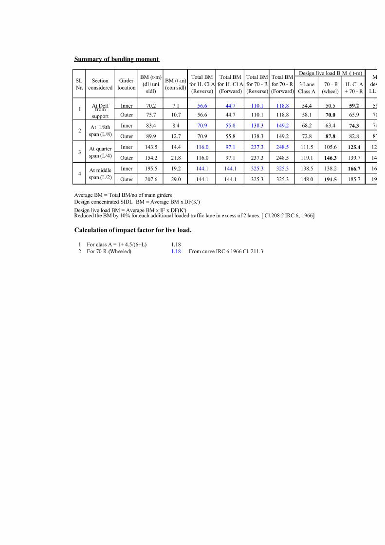
Summary of bending moment
3 Lane
Class A
70 - R
(wheel)
1L Cl A
+ 70 - R
Inner 70.2 7.1 56.6 44.7 110.1 118.8 54.4 50.5 59.2 59
Outer 75.7 10.7 56.6 44.7 110.1 118.8 58.1 70.0 65.9 70
Inner 83.4 8.4 70.9 55.8 138.3 149.2 68.2 63.4 74.3 74
Outer 89.9 12.7 70.9 55.8 138.3 149.2 72.8 87.8 82.8 87
Inner 143.5 14.4 116.0 97.1 237.3 248.5 111.5 105.6 125.4 12
Outer 154.2 21.8 116.0 97.1 237.3 248.5 119.1 146.3 139.7 14
Inner 195.5 19.2 144.1 144.1 325.3 325.3 138.5 138.2 166.7 16
Outer 207.6 29.0 144.1 144.1 325.3 325.3 148.0 191.5 185.7 19
Average BM = Total BM/no of main girders
Design concentrated SIDL BM = Average BM x DF(K')
Design live load BM = Average BM x IF x DF(K')Reduced the BM by 10% for each additional loaded traffic lane in excess of 2 lanes. [ Cl.208.2 IRC 6, 1966]
Calculation of impact factor for live load.
1 For class A = 1+ 4.5/(6+L) 1.18
2 For 70 R (Wheeled) 1.18 From curve IRC 6 1966 Cl. 211.3
BM (t-m)
(dl+uni
sidl)
Girder
location
BM (t-m)
(con sidl)
Total BM
for 1L Cl A
(Reverse)
Total BM
for 70 - R
(Forward)
M
des
LL
Design live load B M ( t-m)Total BM
for 1L Cl A
(Forward)
Total BM
for 70 - R
(Reverse)
At Deff from
support
At quarter
span (L/4)
At middle
span (L/2)
SL.
Nr.
4
3
1
2At 1/8th
span (L/8)
Section
considered

7/14/2019 RCC T BEAM.xls
http://slidepdf.com/reader/full/rcc-t-beamxls 24/33
Design of section for flexure
Inner g r er Outer g r er
SECTIONDeff from
support
L/8 of
span
L/4 of
span
L/2 of
span
Deff from
support
L/8 of
span
L/4 of
span
L/2 of
span
DATA
M (t.m) 136.5 166.1 283.3 381.3 156.4 190.5 322.3 428.1
h (m) 2.000 2.000 2.000 2.000 2.000 2.000 2.000 2.000
bf (m) 2.650 2.650 2.650 2.650 3.400 3.400 3.400 3.400
df (m) 0.250 0.250 0.250 0.250 0.250 0.250 0.250 0.250
bw (m) 0.325 0.325 0.325 0.325 0.325 0.325 0.325 0.325
Ast (m^2) 0.00482 0.00482 0.00804 0.01126 0.00563 0.00563 0.00965 0.01286
c (m) 0.115 0.115 0.124 0.132 0.109 0.109 0.120 0.148
Asc (m^2) 0.00080 0.00040 0.00040 0.00040 0.00080 0.00040 0.00040 0.00040
dc (m) 0.064 0.064 0.064 0.064 0.064 0.064 0.064 0.064
m 10.0 10.0 10.0 10.0 10.0 10.0 10.0 10.0RESULTS
d (m) 1.885 1.885 1.876 1.868 1.891 1.891 1.880 1.852
Asf (m^2) 0.00515 0.00511 0.00513 0.00516 0.00656 0.00652 0.00656 0.00667
AA (m^2) 0.0000 0.0000 0.5813 0.5813 0.0000 0.0000 0.7688 0.7688
A (m) 2.6500 2.6500 0.3250 0.3250 3.4000 3.4000 0.3250 0.3250
B (m^2) 0.1110 0.1037 1.3305 1.3949 0.1270 0.1198 1.7377 1.8020
C (m^3) -0.1828 -0.1823 -0.4474 -0.5663 -0.2138 -0.2133 -0.5554 -0.6691
n (m) 0.243 0.243 0.312 0.373 0.233 0.233 0.303 0.349
CC (m^2) 0.0332 0.0336 0.0635 0.0902 0.0388 0.0391 0.0783 0.1053
jd (m) 1.804 1.804 1.778 1.761 1.814 1.813 1.784 1.749
fc (t/m^2) 231 283 396 481 215 263 359 442
fs (t/m^2) -15677 -19083 -19815 -19232 -15321 -18665 -18723 -19030
Cracked moment of inertia Ir (m4) 0.224 0.296 0.272 0.338
d=h-c
Asf=(bf*df^2+2*(m-1)*Asc*(df-dc))/(2*m*(d-df))
AA=(bf-bw)*df for As<Asf , else 0
A=bw for As<Asf , else bf
B=2*(AA+(m-1)*Asc+m*As)
C=-(AA*df+2*(m-1)*Asc*dc+2*m*As*d)
n=(-B-sqrt(B^2-4*A*C))/(2*A)
CC=(bf-bw)*(min(df,n))^2*(3*n-2*min(df,n))
jd=d-(CC+bw*n^3+6*(m-1)*Asc*(n-dc)*dc)/(6*m*As*(d-n))
fs=-M/(As*jd)fc=-(fs/m)*n/(d-n)

7/14/2019 RCC T BEAM.xls
http://slidepdf.com/reader/full/rcc-t-beamxls 25/33
Calculation of shear force (Live load)
The shear forces in beams has been calculated as per the provisions of Cl 305.12.2 of IRC: 21 ie,
a) For loads at within 5.5m : Greater of the followings.
i) Assuming the deck slab continuous with supports being assumed as unyielding.
ii) By distribution coefficient ie. Morice-Little as used for calculation of bending moments.
b) For loads beyond 5.5m from either supports :
By distribution coefficient ie. Morice-Little as used for calculation of bending moments.
At Deff from support
For class A (Forward train)
Total shear force (from computer print out on previous sheets) = 24.2 t
Component of shear force due to loads within 5.5 m from support. = 11.9 t
Component of shear force due to loads beyond 5.5 m from support. = 12.2 t
For 70 - R (wheel) (Forward train)
Total shear force (from computer print out on previous sheets) = 64.2 t
Component of shear force due to loads within 5.5 m from support. = 31.3 t
Component of shear force due to loads beyond 5.5 m from support. = 32.9 t
Distribution of shear force for 70 - R (wheel)
A. By Morrice - Little's method
1 For inner girder =1.440*64.24*1.18/4 = 27.3 t
2 For outer girder =1.995*64.24*1.18/4 = 37.8 t
B. By continuous beam method [ For loads with in 5.5 m from support ]
15.66 t 15.66 t
1.525
FEM -3.233 5.742
Balance 3.233 -2.871 -2.871
Carryover -1.435 1.616 0.000 -1.435
Balance 1.435 -0.808 -0.808 0.718 0.718
Total M 0.000 3.679 -3.679 -0.718 0.718
Simple SF 18.674 12.646
Elastic SF -1.388 1.388 1.659 -1.659 -0.271 0.271
Reaction
2.65 2.65 2.65
17.29 15.69 -1.93 0.27
1.63m 1.93m

7/14/2019 RCC T BEAM.xls
http://slidepdf.com/reader/full/rcc-t-beamxls 26/33
1 For inner girder = (32.92*1.440/4+15.69)*1.18 = 32.5 t
2 For outer girder = (32.92*1.995/4+17.29)*1.18 = 39.8 t
Design Shear force =Average SF x IF x DF
1 For inner girder = 32.5 t
2 For outer girder = 39.8 t
Distribution of shear force for 1 L Class A + 70 - R (wheel)
A. By Morrice - Little's method
1 For inner girder = =1.34*(24.16*1.18+64.24*1.18)*0.9/4 = 31.4 t
2 For outer girder = =1.49*(24.16*1.18+64.24*1.18)*0.9/4 = 35. t
B. By continuous beam method [ For loads with in 5.5 m from support ]
15.66 t 15.66 t 5.97 t 5.97 t
1.525
FEM -3.233 5.742 -2.063 1.884 -1.762 0.327
Balance 3.233 -1.840 -1.840 -0.061 -0.061 -0.327
Carryover -0.920 1.616 -0.030 -0.920 -0.164 -0.030
Balance 0.920 -0.793 -0.793 0.542 0.542 0.030
Total M 0.000 4.726 -4.726 1.445 -1.445 0.000
Simple SF 18.674 12.646 3.120 2.850 5.035 0.935
Elastic SF -1.783 1.783 1.238 -1.238 0.545 -0.545
Reaction
1 For inner girder = ((12.22+32.92)*1.34/4+18.79)*1.18*0.9 = 36.0 t
2 For outer girder = ((12.22+32.92)*1.49/4+16.89)*1.18*0.9 = 35.8 t
Design Shear force =Average SF x IF x DF
Reduced the SF by 10% for each additional loaded traffic lane in excess of 2 lanes.
[As per clause 208.2 IRC 6, 1966]
1 For inner girder = 36. t
2 For outer girder = 35.8 t
16.89 7.19 0.3918.79
2.65 2.65 2.65
1.63m 1.93m1.8m
1.88m
7/14/2019 RCC T BEAM.xls
http://slidepdf.com/reader/full/rcc-t-beamxls 27/33
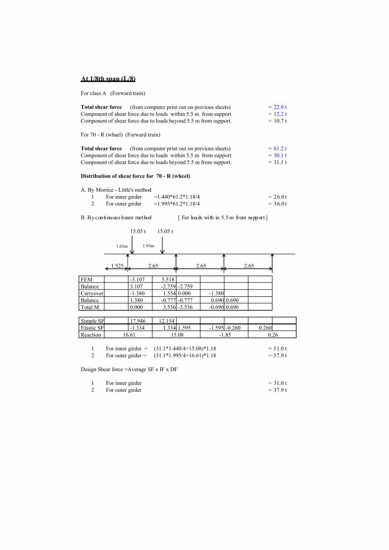
At 1/8th span (L/8)
For class A (Forward train)
Total shear force (from computer print out on previous sheets) = 22.9 t
Component of shear force due to loads within 5.5 m from support. = 12.2 t
Component of shear force due to loads beyond 5.5 m from support. = 10.7 t
For 70 - R (wheel) (Forward train)
Total shear force (from computer print out on previous sheets) = 61.2 t
Component of shear force due to loads within 5.5 m from support. = 30.1 t
Component of shear force due to loads beyond 5.5 m from support. = 31.1 t
Distribution of shear force for 70 - R (wheel)
A. By Morrice - Little's method
1 For inner girder =1.440*61.2*1.18/4 = 26.0 t
2 For outer girder =1.995*61.2*1.18/4 = 36.0 t
B. By continuous beam method [ For loads with in 5.5 m from support ]
15.05 t 15.05 t
1.525
FEM -3.107 5.518
Balance 3.107 -2.759 -2.759
Carryover -1.380 1.554 0.000 -1.380
Balance 1.380 -0.777 -0.777 0.690 0.690
Total M 0.000 3.536 -3.536 -0.690 0.690
Simple SF 17.946 12.154
Elastic SF -1.334 1.334 1.595 -1.595 -0.260 0.260
Reaction
1 For inner girder = (31.1*1.440/4+15.08)*1.18 = 31.0 t
2 For outer girder = (31.1*1.995/4+16.61)*1.18 = 37.9 t
Design Shear force =Average SF x IF x DF
1 For inner girder = 31.0 t
2 For outer girder = 37.9 t
15.08 -1.85 0.26
2.65 2.65 2.65
16.61
1.63m 1.93m

7/14/2019 RCC T BEAM.xls
http://slidepdf.com/reader/full/rcc-t-beamxls 28/33
Distribution of shear force for 1 L Class A + 70 - R (wheel)
A. By Morrice - Little's method
1 For inner girder =1.34*(22.9*1.18+61.2*1.18)*0.9/4 = 29.9 t
2 For outer girder =1.49*(22.9*1.18+61.2*1.18)*0.9/4 = 33.3 t
B. By continuous beam method [ For loads with in 5.5 m from support ]
15.05 t 15.05 t 6.1 t 6.1 t
1.525
FEM -3.107 5.518 -2.108 1.925 -1.801 0.334
Balance 3.107 -1.705 -1.705 -0.062 -0.062 -0.334
Carryover -0.853 1.554 -0.031 -0.853 -0.167 -0.031
Balance 0.853 -0.761 -0.761 0.510 0.510 0.031
Total M 0.000 4.605 -4.605 1.520 -1.520 0.000
Simple SF 17.946 12.154 3.188 2.912 5.145 0.955
Elastic SF -1.738 1.738 1.164 -1.164 0.574 -0.574
Reaction
1 For inner girder = ((10.7+31.1)*1.34/4+18.24)*1.18*0.9 = 34.2 t
2 For outer girder = ((10.7+31.1)*1.49/4+16.21)*1.18*0.9 = 33.7 t
Design Shear force =Average SF x IF x DF
Reduced the SF by 10% for each additional loaded traffic lane in excess of 2 lanes.
[As per clause 208.2 IRC 6, 1966]
1 For inner girder = 34.2 t
2 For outer girder = 33.7 t
18.24 7.47 0.3816.21
2.65 2.65 2.65
1.63m 1.93m 1.8m1.88m
7/14/2019 RCC T BEAM.xls
http://slidepdf.com/reader/full/rcc-t-beamxls 29/33
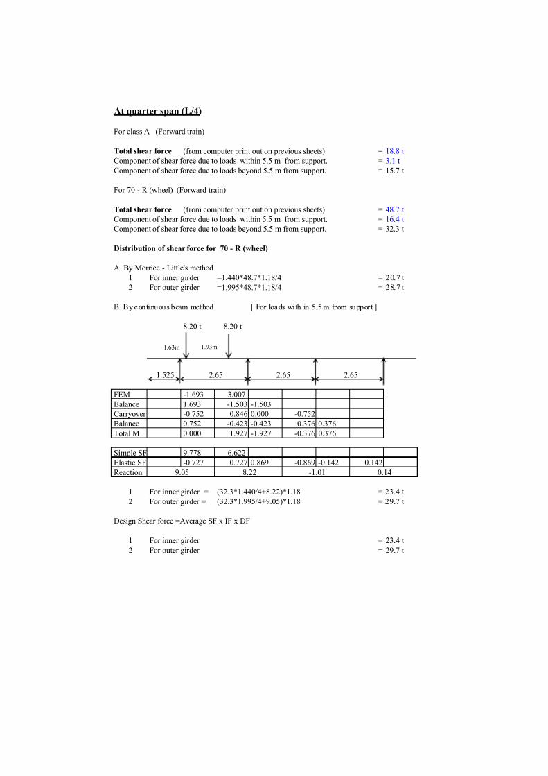
At quarter span (L/4)
For class A (Forward train)
Total shear force (from computer print out on previous sheets) = 18.8 t
Component of shear force due to loads within 5.5 m from support. = 3.1 t
Component of shear force due to loads beyond 5.5 m from support. = 15.7 t
For 70 - R (wheel) (Forward train)
Total shear force (from computer print out on previous sheets) = 48.7 t
Component of shear force due to loads within 5.5 m from support. = 16.4 t
Component of shear force due to loads beyond 5.5 m from support. = 32.3 t
Distribution of shear force for 70 - R (wheel)
A. By Morrice - Little's method
1 For inner girder =1.440*48.7*1.18/4 = 20.7 t
2 For outer girder =1.995*48.7*1.18/4 = 28.7 t
B. By continuous beam method [ For loads with in 5.5 m from support ]
8.20 t 8.20 t
1.525
FEM -1.693 3.007
Balance 1.693 -1.503 -1.503
Carryover -0.752 0.846 0.000 -0.752
Balance 0.752 -0.423 -0.423 0.376 0.376
Total M 0.000 1.927 -1.927 -0.376 0.376
Simple SF 9.778 6.622
Elastic SF -0.727 0.727 0.869 -0.869 -0.142 0.142
Reaction
1 For inner girder = (32.3*1.440/4+8.22)*1.18 = 23.4 t
2 For outer girder = (32.3*1.995/4+9.05)*1.18 = 29.7 t
Design Shear force =Average SF x IF x DF
1 For inner girder = 23.4 t
2 For outer girder = 29.7 t
2.65 2.65 2.65
9.05 8.22 -1.01 0.14
1.63m 1.93m
7/14/2019 RCC T BEAM.xls
http://slidepdf.com/reader/full/rcc-t-beamxls 30/33
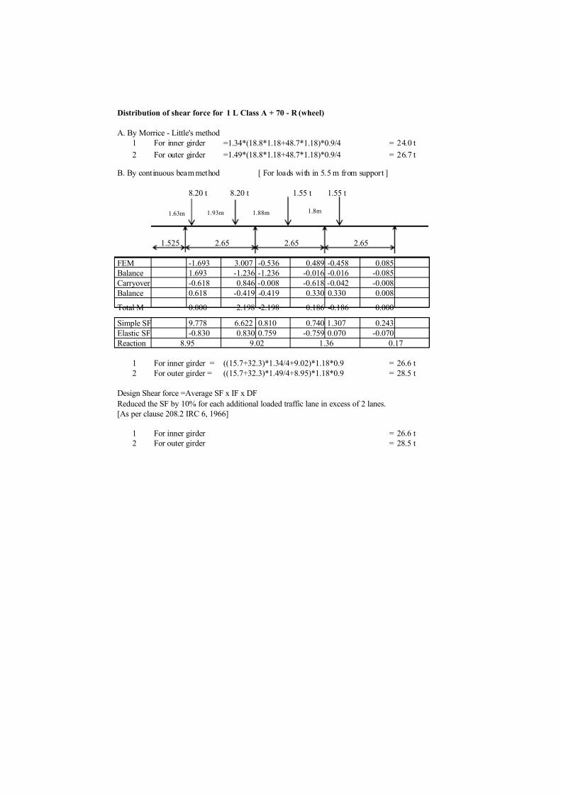
Distribution of shear force for 1 L Class A + 70 - R (wheel)
A. By Morrice - Little's method
1 For inner girder =1.34*(18.8*1.18+48.7*1.18)*0.9/4 = 24.0 t
2 For outer girder =1.49*(18.8*1.18+48.7*1.18)*0.9/4 = 26.7 t
B. By continuous beam method [ For loads with in 5.5 m from support ]
8.20 t 8.20 t 1.55 t 1.55 t
1.525
FEM -1.693 3.007 -0.536 0.489 -0.458 0.085
Balance 1.693 -1.236 -1.236 -0.016 -0.016 -0.085
Carryover -0.618 0.846 -0.008 -0.618 -0.042 -0.008
Balance 0.618 -0.419 -0.419 0.330 0.330 0.008
Total M 0.000 2.198 -2.198 0.186 -0.186 0.000
Simple SF 9.778 6.622 0.810 0.740 1.307 0.243
Elastic SF -0.830 0.830 0.759 -0.759 0.070 -0.070
Reaction
1 For inner girder = ((15.7+32.3)*1.34/4+9.02)*1.18*0.9 = 26.6 t
2 For outer girder = ((15.7+32.3)*1.49/4+8.95)*1.18*0.9 = 28.5 t
Design Shear force =Average SF x IF x DF
Reduced the SF by 10% for each additional loaded traffic lane in excess of 2 lanes.
[As per clause 208.2 IRC 6, 1966]
1 For inner girder = 26.6 t
2 For outer girder = 28.5 t
2.65 2.65 2.65
8.95 9.02 1.36 0.17
1.63m 1.93m 1.8m1.88m
7/14/2019 RCC T BEAM.xls
http://slidepdf.com/reader/full/rcc-t-beamxls 31/33
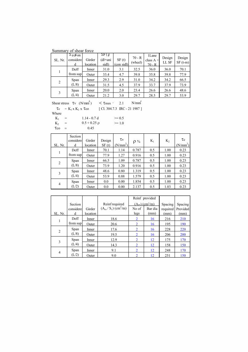
Summary of shear force
SL. Nr.
ect on
considere
d
Girder
location
t
(dl+uni
sidl)
SF (t)
(con sidl)
70 - R
(wheel)
1Lane
class A +
70 - R
Design
LL SF
Design
SF (t-m)
Inner 31.0 3.1 32.5 36.0 36.0 70.1
Outer 33.4 4.7 39.8 35.8 39.8 77.9
Inner 29.3 2.9 31.0 34.2 34.2 66.5
Outer 31.5 4.5 37.9 33.7 37.9 73.9
Inner 20.0 2.0 23.4 26.6 26.6 48.6
Outer 21.2 3.0 29.7 28.5 29.7 53.9
Shear stress tv (N/mm ) < tmax 2.1 N/mm
tc = K 1 x K 2 x tco [ Cl. 304.7.3 IRC - 21 1987 ]
Where
K 1 = 1.14 - 0.7 d >= 0.5
K 2 = 0.5 + 0.25 r >= 1.0
tco = 0.45
SL. Nr.
Sectionconsidere
d
Girder
location
Design
SF (t)
tv
(N/mm2)
r % K 1 K 2tc
(N/mm2)
Inner 70.1 1.14 0.787 0.5 1.00 0.23
Outer 77.9 1.27 0.916 0.5 1.00 0.23
Inner 66.5 1.09 0.787 0.5 1.00 0.23
Outer 73.9 1.20 0.916 0.5 1.00 0.23
Inner 48.6 0.80 1.319 0.5 1.00 0.23
Outer 53.9 0.88 1.579 0.5 1.00 0.23
Inner 0.0 0.00 1.854 0.5 1.00 0.23
Outer 0.0 0.00 2.137 0.5 1.03 0.23
No of
legs
Bar dia
(mm)
Inner 2 16 216 210
Outer 2 16 195 190
Inner 2 16 228 220
Outer 2 16 206 200
Inner 2 12 175 170
Outer 2 12 158 150
Inner 2 12 248 170
Outer 2 12 251 150
Spacing
Provided
(mm)
Reinf provided
(Asv) (cm2/m)
Girder
location
Reinf required(Asv / Sv) (cm
2/m)
Spacing
required
(mm)SL. Nr.
Section
considere
d
3
4Span
(L/2)
2
Deff
from sup
Span
(L/8)
Span
(L/4)
1
2Span
(L/8)
4Span
(L/2)
3Span
(L/4)
9.1
9.0
18.6
20.6
12.9
14.3
17.6
19.5
1Deff
from sup
1Deff
from sup
3Span
(L/4)
2Span
(L/8)
7/14/2019 RCC T BEAM.xls
http://slidepdf.com/reader/full/rcc-t-beamxls 32/33
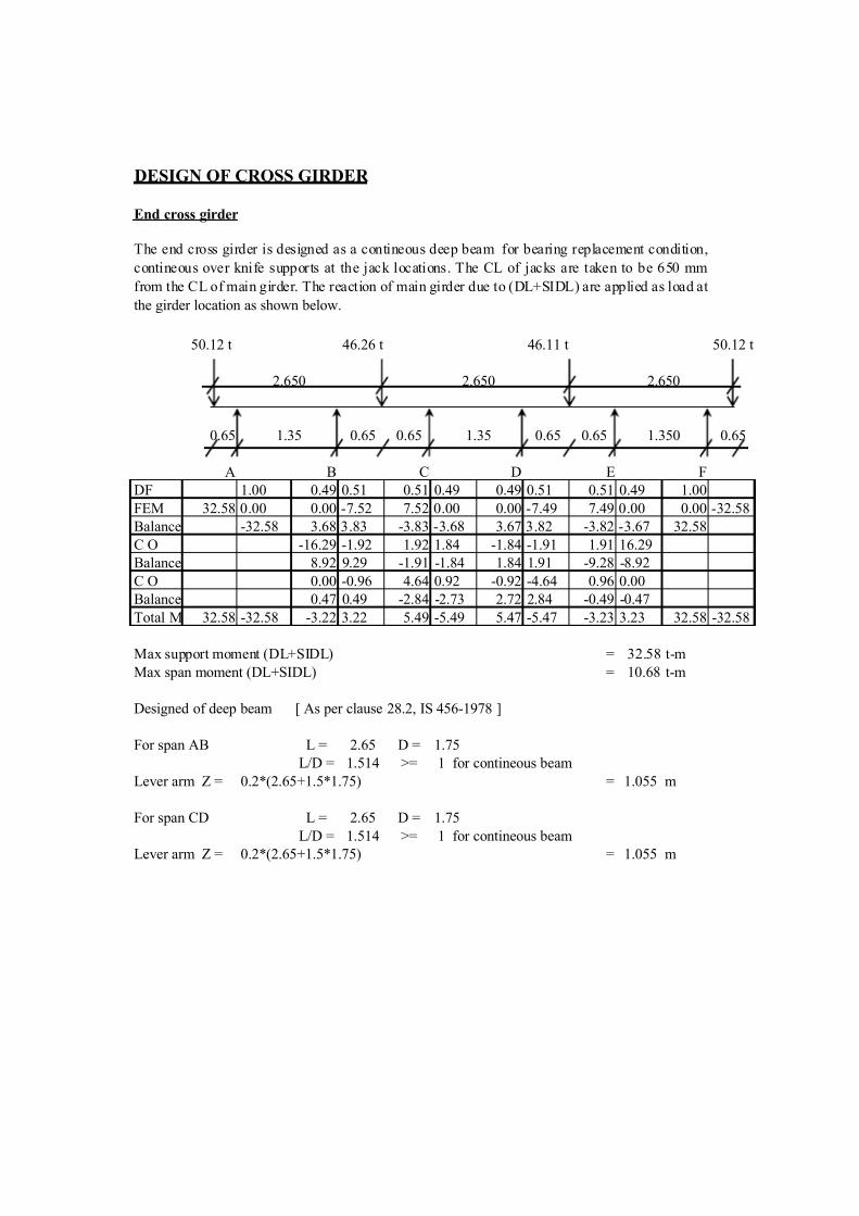
DESIGN OF CROSS GIRDER
End cross girder
50.12 t 46.26 t 46.11 t 50.12 t
0.65 0.65 0.65 0.65 0.65 0.65
A B C D E F
DF 1.00 0.49 0.51 0.51 0.49 0.49 0.51 0.51 0.49 1.00
FEM 32.58 0.00 0.00 -7.52 7.52 0.00 0.00 -7.49 7.49 0.00 0.00 -32.58
Balance -32.58 3.68 3.83 -3.83 -3.68 3.67 3.82 -3.82 -3.67 32.58
C O -16.29 -1.92 1.92 1.84 -1.84 -1.91 1.91 16.29
Balance 8.92 9.29 -1.91 -1.84 1.84 1.91 -9.28 -8.92
C O 0.00 -0.96 4.64 0.92 -0.92 -4.64 0.96 0.00
Balance 0.47 0.49 -2.84 -2.73 2.72 2.84 -0.49 -0.47
Total M 32.58 -32.58 -3.22 3.22 5.49 -5.49 5.47 -5.47 -3.23 3.23 32.58 -32.58
Max support moment (DL+SIDL) = 32.58 t-m
Max span moment (DL+SIDL) = 10.68 t-m
Designed of deep beam [ As per clause 28.2, IS 456-1978 ]
For span AB L = 2.65 D = 1.75
L/D = 1.514 >= 1 for contineous beam
Lever arm Z = 0.2*(2.65+1.5*1.75) = 1.055 m
For span CD L = 2.65 D = 1.75
L/D = 1.514 >= 1 for contineous beam
Lever arm Z = 0.2*(2.65+1.5*1.75) = 1.055 m
2.650
The end cross girder is designed as a contineous deep beam for bearing replacement condition,
contineous over knife supports at the jack locations. The CL of jacks are taken to be 650 mm
from the CL of main girder. The reaction of main girder due to (DL+SIDL) are applied as load at
the girder location as shown below.
2.650 2.650
1.35 1.3501.35
7/14/2019 RCC T BEAM.xls
http://slidepdf.com/reader/full/rcc-t-beamxls 33/33
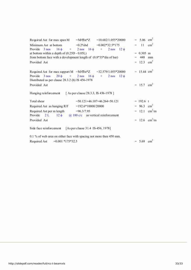
Required Ast for max span M =M/sst*Z =10.682/1.055*20000 = 5.06 cm2
Minimum Ast at bottom =0.2%bd =0.002*32.5*175 = 11 cm2
Provide 3 nos 16 f + 2 nos 16 f + 2 nos 12 f
at bottom within a depth of (0.25D - 0.05L) = 0.305 m
from bottom face with a development length of (0.8*35*dia of bar) = 448 mm
Provided Ast = 12.3 cm2
Required Ast for max support M =M/sst*Z =32.579/1.055*20000 = 15.44 cm2
Provide 3 nos 20 f + 2 nos 16 f + 2 nos 12 f
Distributed as per clause 28.3.2 (b) IS 456-1978
Provided Ast = 15.7 cm2
Hanging reinforcement [ As per clause 28.3.3, IS 456-1978 ]
Total shear =50.121+46.107+46.264+50.121 = 192.6 t
Required Ast as hanging R/F =192.6*10000/20000 = 96.3 cm2
Required Ast per m length =96.3/7.95 = 12.1 cm2/m
Provide 2 L 12 f as vertical reinforcement
Provided Ast = 12.6 cm2/m
Side face reinforcement [As per clause 31.4 IS-456, 1978]
0.1 % of web area on either face with spacing not more then 450 mm.
Required Ast =0.001 *175*32.5 = 5.69 cm2
@ 180 c/c