Rationalization of LRFD Method for Safe Bearing Capacity ...
13
Rationalization of LRFD Method for Safe Bearing Capacity of Shallow Footings to Incorporate the Type of Shear Failure Ronak Kotadia 1 , K. N. Sheth 2 and Avani Malaviya 3 1&3 M.Tech in Geotechnical Engineering, Dharmsinh Desai University, Nadiad – 387 001 E-mail: [email protected]; [email protected]; 2 Head, Civil Engineering Department, Dharmsinh Desai University, Nadiad – 387 001 E-mail: [email protected] Abstract. The geotechnical design philosophy is in the transformation stage to implement Load and Resistance Factor Design (LRFD). IS 6403 uses working stress method to calculate safe bearing capacity for shallow foundations, while Euro Code 7 and AASHTO use the LRFD method and provide guidelines for proportioning shallow foundations using partial safety factors. Hence, in order to adopt the LRFD design method, it has to be rationalized to have the convincing bearing capacity with respect to IS Code results to incorporate the shear failure criteria. In present work, safe bearing capacity for shallow footing is calculated as per IS Code, Euro Code 7 and AASHTO by taking the variations in shear failure criteria i.e. with and without consideration of shear failure criteria (only for Euro Code design), soil parameters (cohesion, C and angle of internal friction, ϕ), size and depth of footing. Problems are then identified by checking the consistency of results obtained by Euro Code 7 and AASHTO with respect to IS Code results. Further, as a part of rationalization, the recommendation is given that in Euro Code 7 design, the partial safety factors must be applied to bearing capacity factors, instead of applying to soil properties (C, ϕ). Also, net safe load (kN) obtained from AASHTO is on lower side as compare to IS results because it considers higher average FOS than IS Code. Keywords: LRFD; shallow footings; codes; rationalization; shear failure criteria. 1. Introduction Structural Design Philosophy and implementation to Codes of Practice has transformed from conventional Working Stress Method to Limit State Method - Load and Resistance Factor Design (ACI) or Partial Safety Factor approach (IS Code). Geotechnical Design Philosophy is in the transformation stage to implement Load and Resistance Factor Design (LRFD). IS 6403 provides guideline to calculate ultimate bearing capacity for shallow foundations. It gives bearing capacity factors and other
Transcript of Rationalization of LRFD Method for Safe Bearing Capacity ...

Rationalization of LRFD Method for Safe BearingCapacity of Shallow Footings to Incorporate the Type of
Shear Failure
Ronak Kotadia1, K. N. Sheth2 and Avani Malaviya3
1&3M.Tech in Geotechnical Engineering, Dharmsinh Desai University, Nadiad – 387 001E-mail: [email protected]; [email protected];
2Head, Civil Engineering Department, Dharmsinh Desai University, Nadiad – 387 001E-mail: [email protected]
Abstract. The geotechnical design philosophy is in the transformation stage toimplement Load and Resistance Factor Design (LRFD). IS 6403 uses workingstress method to calculate safe bearing capacity for shallow foundations, whileEuro Code 7 and AASHTO use the LRFD method and provide guidelines forproportioning shallow foundations using partial safety factors. Hence, in orderto adopt the LRFD design method, it has to be rationalized to have theconvincing bearing capacity with respect to IS Code results to incorporate theshear failure criteria. In present work, safe bearing capacity for shallow footingis calculated as per IS Code, Euro Code 7 and AASHTO by taking thevariations in shear failure criteria i.e. with and without consideration of shearfailure criteria (only for Euro Code design), soil parameters (cohesion, C andangle of internal friction, ϕ), size and depth of footing. Problems are thenidentified by checking the consistency of results obtained by Euro Code 7 andAASHTO with respect to IS Code results. Further, as a part of rationalization,the recommendation is given that in Euro Code 7 design, the partial safetyfactors must be applied to bearing capacity factors, instead of applying to soilproperties (C, ϕ). Also, net safe load (kN) obtained from AASHTO is on lowerside as compare to IS results because it considers higher average FOS than ISCode.
Keywords: LRFD; shallow footings; codes; rationalization; shear failurecriteria.
1. Introduction
Structural Design Philosophy and implementation to Codes of Practice hastransformed from conventional Working Stress Method to Limit State Method - Loadand Resistance Factor Design (ACI) or Partial Safety Factor approach (IS Code).Geotechnical Design Philosophy is in the transformation stage to implement Load andResistance Factor Design (LRFD). IS 6403 provides guideline to calculate ultimatebearing capacity for shallow foundations. It gives bearing capacity factors and other

factors viz. inclination factors, depth factors, shape factors etc. and accounts for theeffect of water table. To calculate allowable bearing pressure, a Factor of Safety 2.50is recommended separately by IS 1080. Eurocode 7 uses LRFD method and providesguideline for proportioning shallow foundations using partial safety factors forAction, Material Parameters and Resistance. The Action includes Dead Loads as wellas Imposed Loads. Material Parameters includes shear parameters ‘c’ and ‘φ’ indrained and/or undrained state. The Resistance Factors are assigned based on thedesign methods used. For shallow foundations, three design approaches areconsidered, for which partial safety factors are given. In Euro Code 7, shear failurecriteria is not considered for design as in case of IS Code. As per the AASHTOLRFD, resistance side of the equation is multiplied by the statistically based resistancefactor, φ, whose value is usually less than one. As applied to the geotechnical designof substructures, φ accounts for factors such as weaker foundation soils than expected,poor construction of the foundations, and foundation materials such as concrete, steelor wood that may not completely satisfy the requirements in the specifications. Alsothe partial factors for different load cases and load combination has been provided toget the design action. When properly developed and applied, the LRFD approachprovides a consistent level of safety for the design of all structure components.
Euro Code 7 uses three partial safety factors i.e. for load action, material parameterand resistance, while AASHTO uses two partial safety factors i.e. for load action andresistance. Unlike IS Code and AASHTO, Euro Code 7 does not consider any kind ofshear failure criteria for SBC calculation. Thus, the design philosophies adopted byEuro Code 7 and AASHTO differs from that of IS Code, Safe Bearing Capacity forshallow footing calculated as per these codes widely differs from each other. Hence,in order to adopt Euro Code 7 LRFD design method for calculation of SBC of shallowfooting, it has to be rationalized in order to have the consistent results with respect toIS Code results to incorporate the shear failure criteria given by IS.
2. Method
The safe bearing capacity of shallow foundation as per IS Code, EC 7 and AASHTOare calculated for various range of soil parameter (C and ϕ) for a strip and squarefooting with variation in size and depth of foundation on a soil with bulk density 18kN/m3 and FOS of 2.5 for IS design as follows
Table 1. Parametric study
Parameter VariationsCohesionless soil with ϕ 24º to 44º
Cohesive soil with C (kN/m2)(at interval of 15)
Upto 200 kN/m2
Size of strip footing, m21 x 5 m2
2 x 10 m2
3 x 15 m2
4 x 20 m2
Size of square footing, m2
1 x 1 m2
2 x 2 m2
3 x 3 m2
4 x 4 m2
Depth of footing D , m 0 to 3 m
Since Euro Code 7 is silent about shear failure criteria, for the pure cohesionless andcohesive soil, two cases in Euro code design are considered as follow:EC7 (I): Considering type of shear failure based on factored values of angle offriction.EC7 (II): Without considering type of shear failure based on angle of friction andusing general parameters for all values.The results are obtained for all the problems in terms of Net Safe Load (kN). Also, thegraphs of net safe load ratio i.e. EC7 (I)/IS and AASHTO/IS vs soil properties (C, ϕ)are plotted for varying Df/B. Let this be considered as Case I: Partial safety factorsapplied to soil properties (C, ϕ) as prescribed by Euro Code provision.
2.1 Theoretical Formulation
2.1.1 Formulation as per IS 6403:1981
For General Shear Failure Criteriaq = * C N d s i + q (N - 1) d s i + 0.5 B γ N d s i Wʹ
For Local Shear Failure Criteriaq = * C N′ d s i + q (N - 1) d s i + 0.5 B γ N′ d s i WʹWhere,q = Net allowable bearing pressure, kN/mN , N , N = Bearing capacity factors based on ϕ for general shear failureN′ , N′ , N′ = Bearing capacity factors based on ϕ for local shear failure,
where, ϕ = tan (0.67 tan ϕ)B = Width of footingD = Depth of footingγ = Unit weight of footingWʹ = Effect of water tabled , d , d = Depth factorss , s , s = Shape factorsi , i , i = Inclination factors = 1 for vertical loads
Table 2. Shape Factors
Sr. No. Shape of base
1 Continuous strip 1 1 1

2 Rectangle 1 + 0.2 B/L 1 + 0.2 B/L 1 - 0.4 B/L3 Square 1.3 1.2 0.84 Circle 1.3 1.2 0.6
Table 3. Depth Factors
Sr. No. Depth factor1 d 1 + 0.2 (D/B) N2 d = d 1 for ϕ < 103 d = d 1 + 0.1 (D/B) N for ϕ >10
Table 4. Effect of Water Table
Wʹ 1 if D > (D + B)0.5 if D < D & for GWT at and above footing level
For Mixed Shear Failureq = * C N˝ d s i + q (N˝ - 1) d s i + 0.5 B γ N˝ d s i WʹWhere,N˝ = Nˊ + ( ) * differenceN˝ = Nˊ + ( ) * differenceN˝ = Nˊ + ( ) * difference
Difference = ϕ - 28º, ϕ =29º to 35º
2.1.2 Formulation as per Eurocode 7
ULS verifications are carried out with the three possible Design Approaches:DA1 – Combination 1: A1 + M1 + R1DA1 – Combination 2: A2 + M2 + R1DA2: A1 + M1 + R2DA3: (A1/A2)* + M2 + R3*A1 is for Structural actions and A2 is for Geotechnical actions.
Table 5. L-M-R Combination for Shallow Foundation
Partial safety factor
Design Action Material Resistance

approach PermanentloadγG
VariableloadγQ
Drainedγϕ, γC
UndrainedγCu
BearingγRv
DA1-C1 1.35 1.50 1.00 1.00 1.00
DA1-C2 1.00 1.30 1.25 1.40 1.00
DA2 1.35 1.50 1.00 1.00 1.40
DA3 1.00 1.30 1.25 1.40 1.00
For Drained Conditions:
The design bearing resistance is calculated as:R/Aʹ = Cʹ N b s i + qʹ N b s i + 0.5 Bʹ γˊ N b s i
Where, N = e ʹ tan (45 +ʹ)N = (N – 1) cot ϕʹN = 2(N – 1) tanϕʹ
are dimensionless factors for bearing resistance andb , b , b = Inclination factors of the foundation bases , s , s = Shape factors of foundationi , i , i = Inclination factors of loadAʹ = Bʹ Lʹ = Effective foundation area
Table 6. Shape Factor for Drained Condition
Shape factor Value Shape of footings (s N −1) (N −1) Rectangular, square or circulars 1 + (Bʹ/Lʹ) sinϕʹ Rectangular1 + sin ϕʹ Square or circulars 0.7 Square or circular
1 - 0.3 (Bʹ/Lʹ) Rectangular
2.1.3 Formulation as per AASHTO
The AASHTO LRFD specifications prescribe the procedures used to compute loadsand detail how to factor and combine the loads for comparing to the factoredresistance.For the present work, the partial safety factor for permanent and live load areconsidered as 1.25 and 1.75 respectively.
Bearing Resistance of soil :The factored resistance, q , at the strength limit state shall be taken as:q = ϕ ∗ qWhere,

ϕ = Resistance factor ( taken as 0.45 as per AASHTO specifications for all soil)q = Nominal bearing resistance (ksf) .
The nominal bearing resistance of a soil layer, in ksf, should be taken as:q C N + q N C + 0.5 B γ N Cin which,N = N s iN = N d s iN = N s iWhere,N , N , N = Bearing capacity factorsN = (N -1)cot ϕ, (from Prandtl, 1921)N = e ∗ tan (45 + ), (from Reissner, 1924)N = 2(N +1)tanϕ, (from Vesic, 1975)C = Cohesion, (ksf)Φ = Friction angleB = Width of footing (ft)D = Depth of footing (ft)γ = Unit weight of footing (kcf)C , C = Correction factor for GWTd = Depth correction factors , s , s = Shape correction factorsi , i , i = Inclination factors = 1 for vertical loads
Table 7. Shape Correction Factor
Factor Friction angleCohesion term
(s )Unit weight
term (s )Surcharge term
(s )
Shape factors , s , s ϕ = 0 1 + ( ) 1 1
ϕ > 0 1 + ( )( ) 1 - 0.4 ( ) 1 + ( tanϕ)
Table 8. Correction for Groundwater DepthD (ground water depth) C C0 0.5 0.5D 1 0.5
>1.5B + D 1 1
If local or punching shear failure is possible, the nominal bearing resistance shall beestimated using reduced shear strength parameters C* and Φ* in nominal bearingresistance equation. The reduced shear parameters may be taken asC* = 0.67 C
Φ* = tan (0.67 tanϕ)
3. Results and Discussion
3.1 Results and Observation Obtained from Parametric Study.
Some representative results obtained from parametric study are shown below:
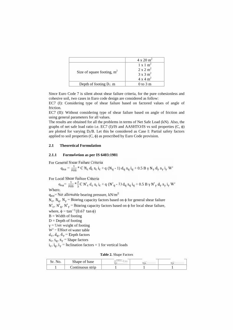
Fig. 1. Net safe load ratio vs ϕ for EC7 (I) Case I (4m x 4m)
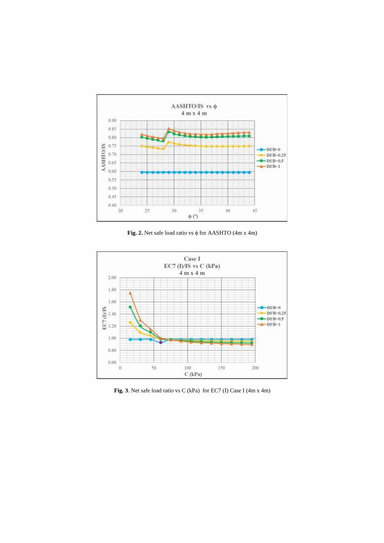
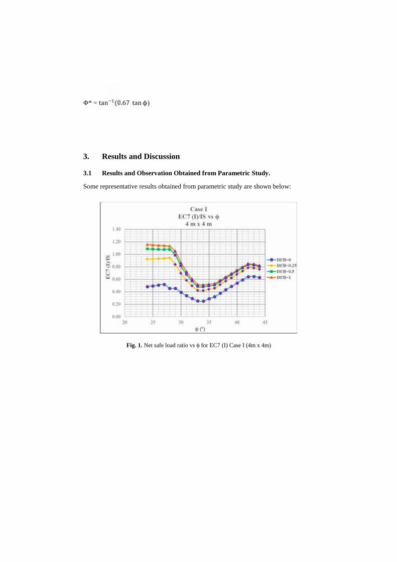
Fig. 2. Net safe load ratio vs ϕ for AASHTO (4m x 4m)
Fig. 3. Net safe load ratio vs C (kPa) for EC7 (I) Case I (4m x 4m)
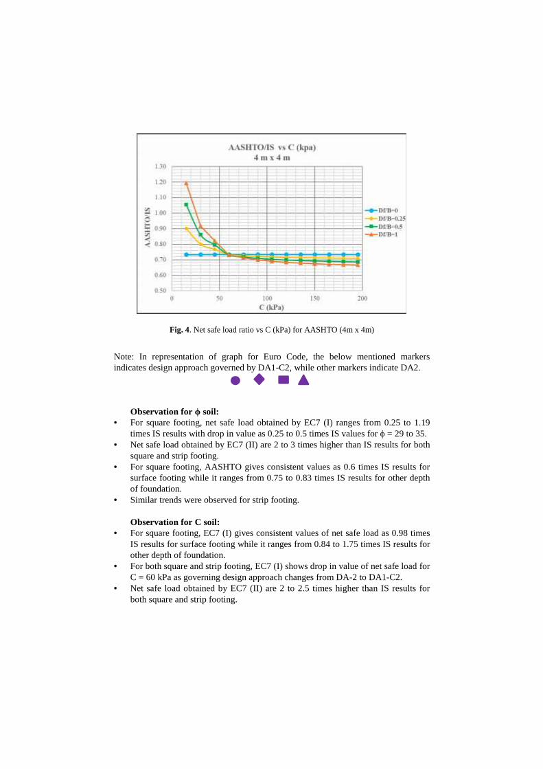
Fig. 4. Net safe load ratio vs C (kPa) for AASHTO (4m x 4m)
Note: In representation of graph for Euro Code, the below mentioned markersindicates design approach governed by DA1-C2, while other markers indicate DA2.
Observation for ϕ soil: For square footing, net safe load obtained by EC7 (I) ranges from 0.25 to 1.19
times IS results with drop in value as 0.25 to 0.5 times IS values for ϕ = 29 to 35. Net safe load obtained by EC7 (II) are 2 to 3 times higher than IS results for both
square and strip footing. For square footing, AASHTO gives consistent values as 0.6 times IS results for
surface footing while it ranges from 0.75 to 0.83 times IS results for other depthof foundation.
Similar trends were observed for strip footing.
Observation for C soil: For square footing, EC7 (I) gives consistent values of net safe load as 0.98 times
IS results for surface footing while it ranges from 0.84 to 1.75 times IS results forother depth of foundation.
For both square and strip footing, EC7 (I) shows drop in value of net safe load forC = 60 kPa as governing design approach changes from DA-2 to DA1-C2.
Net safe load obtained by EC7 (II) are 2 to 2.5 times higher than IS results forboth square and strip footing.

For square footing, AASHTO gives consistent values as 0.73 times IS results forsurface footing while it ranges from 0.63 to 1.20 times IS results for other depthof foundation.
3.2 Recommendation and Results Obtained from Revised Parametric Study:
On the basis of the above observation and as a part of rationalization, another case forEuro Code 7 is considered where partial safety factors are applied to bearing capacityfactors (NC, Nq, Nγ) instead of material properties (C, ϕ) in order to incorporate theshear failure criteria in Euro Code design and to bring the results in considerablerange with respect to IS Code design. Considering the above recommended case, theparametric study is repeated for all variations mentioned in table 1 to get the revisednet safe load (kN). Let this be considered as Case II: Partial safety factors applied tobearing capacity factors (NC, Nq, Nγ), recommended as a part of rationalization toincorporate shear failure criteria in Euro Code design. Some of the results obtainedfrom this revised parametric study is shown below in order to compare with theresults obtained from case I shown above.

Fig. 5. Revised Net safe load ratio vs ϕ for EC7 (I) Case II (4m x 4m)
Fig. 6. Revised Net safe load ratio vs C (kPa) for EC7 (I) Case II (4m x 4m)
4. Observations Obtained From Revised Parametric Study:
For ϕ soil: For square footing, case I gives net safe load by EC7 (I) ranging from 0.25 to
1.19 times IS results, while case II gives this range as 0.98 to 1.25, therebyshowing reasonable results of Euro Code with respect to IS Code.
The drop observed in net safe load ratio EC7 (I)/IS obtained for ϕ = 29 to 35 forcase I is removed by considering case II.
For surface footing, net safe load ratio EC7 (I)/IS for case II varies from 0.51 to0.62 for local shear failure, thereby showing the need of change in depthcorrection factor.
The net safe load obtained from EC7 (II) are quite on higher side with respect toIS results for both case I and case II and hence, it is not advisable to consider EC7(II) for design of shallow footing.
AASHTO gives consistent values as 0.6 times IS results for surface footing whileit ranges from 0.75 to 0.83 times IS results for other depth of foundation. Thedifferences in results are due to the fact that the average factor of safety adoptedby AASHTO is 3.15, whereas that of IS Code is 2.5.
Similar trends were observed for strip footing as well with slight variation in netsafe load ratio.
For C soil:
There is no difference in results obtained by case I and case II for both square andstrip footing.
For both square and strip footing, EC7 (I) shows drop in value of net safe load forC = 60 kPa for case I as governing design approach changes from DA-2 to DA1-C2, while for case II, no such drop in value is observed as the governing designapproach for case II is DA2.
Net safe load obtained by EC7 (II) are 2 to 2.5 times higher than IS results forboth square and strip footing designed by both case I and case II, which is notconsiderable.
For square footing, AASHTO gives consistent values as 0.73 times IS results forsurface footing while it ranges from 0.63 to 1.20 times IS results for other depthof foundation. For strip footing, AASHTO gives consistent values as 0.79 timesIS results for surface footing while it ranges from 0.68 to 1.39 times IS results forother depth of foundation. The differences in results are due to the fact that theaverage factor of safety adopted by AASHTO is 3.15, whereas that of IS Code is2.5.
Thus, from above all observations, it can be recommended that for Euro Code design,material partial safety factors must be applied to bearing capacity factors (NC, Nq,Nγ) instead of applying to material properties in order to incorporate the shear failurecriteria for Euro design.
References
AASHTO LRFD Bridge Design Specifications (2012), American Association ofState Highway and Transportation Officials, Washington, DC.
Andrew J. Bond, Bernd Schuppener, Giuseppe Scarpelli, Trevor L.L. Orr. (2013)Eurocode 7: Geotechnical Design Worked examples. by Joint Research Centre, Italy.
Bond, A. J., and Harris, A. J. (2008). Decoding Eurocode 7, London: Taylor &Francis, pp.618.
IS 6403:1981 (Reaffirmed 2002). Indian Standard Code of Practice for Determinationof Breaking Capacity of Shallow Foundations, (First Revision). Bureau of IndianStandards, New Delhi.
Joseph E. Bowles, RE., S.E.(1997). Foundation analysis and design. by The McGraw-Hill Companies, Inc.,New York.
L. C. Reese, William M. Isenhower, Shin-Tower Wang (2006). Analysis and designof shallow and deep foundation. John Wiley & Sons, Inc., New Jersey.
M. J. Tomlinson (2007). Foundation design and construction. by Pearson EducationLtd. England.

Swami Saran. Shallow foundation and soil constitutive laws. by CRC Press, Taylorand Francis Group, New York
V. N. S. Murthy (2007). Advanced foundation engineering (Geotechnical series). byCBS Publishers and Distributors, New Delhi.