![[AoR] Beginners' Game](https://static.fdocuments.us/doc/165x107/577cc01c1a28aba7118ee41b/aor-beginners-game.jpg)
RATH® Analog AOR Systems Installation
59
RATH® Analog AOR Systems Installation Instructor: Jerry Last Title: Technical Services Superintendent Subject: Installation of Analog AOR Systems
Transcript of RATH® Analog AOR Systems Installation

RATH®
Analog AOR
Systems
InstallationInstructor: Jerry Last
Title: Technical Services Superintendent
Subject: Installation of Analog AOR Systems

Level: Installer and Above
Objectives: Properly install and troubleshoot RATH®
SmartRescue and Command Center Systems
Objectives and
Target

Identify equipment, wiring, and programming
requirements to ensure successful implementation of
both styles of Emergency Communication Systems.
Including but not limited to:
▪ Equipment
▪ Tools needed
▪ Wiring requirements
▪ Base programming (as applicable)
▪ Endpoint programming
▪ Basic troubleshooting techniques
Overview
Tool Recommendations for Emergency
Communication Systems
Multi-meter
Analog phone or telephone
test set
110 Punch Tool
Phillips Head Jeweler's
screwdriver
Wire Cutter
Wire Stripper
Tone generator and
inductive amp
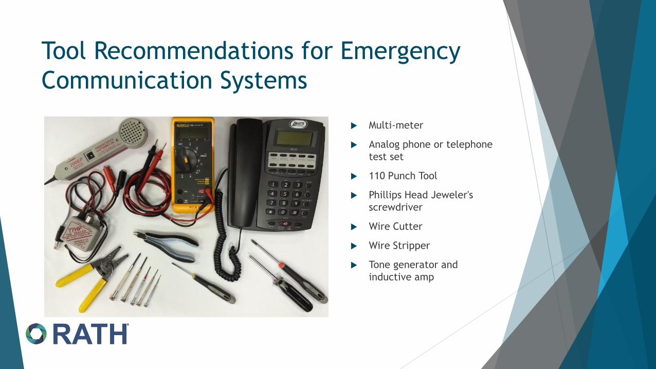
Main Systems
Command CenterSmartRescue

SmartRescue

Available in 5 or 10 Base Station
MUST HAVE:
2100 Series (SmartPhone) call stations
Communications Connection (Either a Loop-Start Central Office Line, an Analog Station Port from a telephone system)
Power Source
Internal Battery (Supplied) Connected
Endpoints (Properly Wired and programmed)
Optional:
Additional Sub-Masters (alternate control points) may be added (up to 2)
SmartRescue

Hardware Installation- Base Station
Install back-box and plan which conduit knockouts are needed for analog communications line, station cabling and power runs
Mount SmartRescue to the box using suitable mounting screws and tools
Test Analog communications by placing a call in and out on the provided line, then to destination number
Connect Analog Phone line to provided connector on SmartRescue circuit board

Station Connections to Base Station
Take 4-Wire Cabling, strip 1/8”
insulation, and insert into the
push connectors
Terminate all 4 conductors in
proper order, to connect wires
to endpoints

General Wiring Diagram

Sub-Masters with
SmartRescue
Up to 2 Sub-Masters can be
installed on the SmartRescue
The Sub-Master can
communicate with all
endpoints connected
(individually or collectively) as
well as any conversation
occurring with SmartRescue
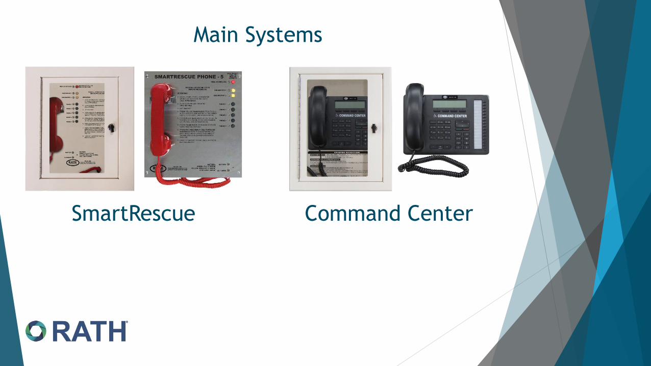
Pre-Installation
Requirements
Install a standard 4 pin (2-pair)
wall jack in the desired location
Twisted, shielded, solid conductor
24 or 22-gauge, 4 conductor wire
between a standard 4 conductor
wall jack and SmartRescue
Hang the Sub-Master on the wall
jack

Power Options - Base Station Direct wire to a 120VAC Power Source or 24VDC from the RATH® 2500-PWR24U
Plug-In Transformer Hard Wired Transformer2500-PWR24U 24VDC
Power Supply

Base Station 120VAC
Power Connection
Connect the Hot Wire of the 120VAC to the “L” screw on the power supply
Connect the Neutral Wire of the 120VAC to the “N” screw
Connect the Ground Wire of the 120VAC to the “Ground” screw
Check DCV across the –V screw and the +V screw, and adjust potentiometer to 24VDC
Connect leads of the DC power input connection to the + and –V output terminals on the transformer
Reinstall the Front Cover

Power/Battery Indicator
When proper power is
applied and included
battery connected, the AC
Power LED should be on and
the battery should be
illuminated in one of the
following:
Red- Low Level Charge
Yellow- Mid Level
Charge
Green- Full Charge

Connected Call stations will function according to
Base Programming. When a call is initiated:
▪ Calls go to the Base and then call an outside Emergency
Number
▪ Calls go directly an outside number only (This is the
default)
If you would like the call to go the base first, you
must program the base accordingly, if not, you may
skip this step and proceed in programming the
Endpoints
Programming
the Base
Station

Programming the
Base Station
For Endpoints to call the Base Station first then call outside:
▪ Leave Handset on hook
▪ Hold Down the Red Disconnect and Sub Master 1 Button for 5 seconds (a high pitch tone will be heard)
▪ Release the Buttons (a confirmation tone is heard)
▪ Press the Phone 2 button, the Red Disconnect Button, then the Phone 1 button (a confirmation tone is heard)
▪ Press the Sub-Master 2, then the Sub-Master 1 button (System will restart)

Programming the
Base Station (cont.)
To Restore Default (Call Outside Number)
Leave Handset on hook
Hold Down the Red Disconnect and Sub Master 1 Button for 5 seconds (a high pitch tone will be heard)
Release the Buttons (a confirmation tone is heard)
Press the Phone 2 button, the Red Disconnect Button, the Sub-Master 2 button, then the Phone 5 button (Confirmation tone will be heard)
Press the Sub-Master 2, then the Sub-Master 1 button (System will reset)

Hardware Installation- EndpointsFollow recommended installation for type of endpoint installed with system

Follow best practices for connecting endpoints
Landing feeder cables on the provided jack
Crimp an RJ-11 end on feeder
Make a solid conductor Pig-Tail line cord to splice via
conventional means
Call Station
Wiring

Cut the end off of the provided phone cable and
direct splice the wires to feeder cable
Scotch lock or use “dolphin” connectors directly on
line cordsDO NOT

Programming
Endpoints
Endpoints will either call Base Station first, then call outside numbers or call outside numbers first depending on Base programming.
Programming will be performed at each endpoint connected to the SmartRescue.
Program THE SAME number into memory slots 1 and 2. This accommodates either Base programming option.

System Operation
To Initiate a Call to a Endpoint from the SmartRescue
▪ Lift Handset on the SmartRescue
▪ Press the black button corresponding to desired phone
▪ The Green LED will illuminate next to the button and 2-Way Communication will occur.
▪ The station’s black button is a Call/Hold/Resume toggle button.
▪ Hanging up the handset disconnects all calls whether on hold or active.

System Operation
To Call the SmartRescue from an Endpoint
Press Call button on Endpoint
If system is programmed for calls to go to Base first, an audible alert is heard at the SmartRescue Base Station
Lift Handset on the SmartRescue for 2-Way Communication
Green LED next to button of calling station will be illuminated
Call can be put on hold or disconnected

System
Operation
Endpoints call SmartRescue, then an Outside Number
Press Call Button on front of Endpoint
If settings and wiring correct, an audible alarm will come from the SmartRescue, indicating a call
If call is not answered within 6 rings, the Endpoint will hang-up and dial the 2nd programmed number and the Base begins a 90 second timer to allow all calls during that time to directly access the phone line to dial out
When the call is answered by the outside party, 2-way communication with the endpoint will begin
At any time the handset can be lifted at the SmartRescue to join the conversation between the endpoint and the outside number
To disconnect the outside number from the call, press the Red Disconnect button on the SmartRescue. This will drop communication with the outside line but continue communication between the base and endpoint until the handset is hung up.

Sub-Master Operation There is no additional programming needed for
the Sub-Master phone
Lift handset on Sub-Master Phone
Press “*, 0” to talk into all endpoints connected to SmartRescue
To talk to individual endpoints select one of the following:
▪ Phone 1: “*, 1”
▪ Phone 2: “*, 2”
▪ Phone 3: “*, 3”
▪ Phone 4: “*, 4”
▪ Phone 5: “*, 5”
▪ Phone 6: “#, 1”
▪ Phone 7: “#, 2”
▪ Phone 8: “#, 3”
▪ Phone 9: “#, 4”
▪ Phone 10: “#, 5”
Hang up the handset to disconnect all calls

Required in some areas
Must have additional wire pair to endpoints
Endpoint can provide either normally open or closed
contact
Connection to additional device for notification
required
DO NOT APPLY VOLTAGE TO ALARM CONTACTS
System
Supervision
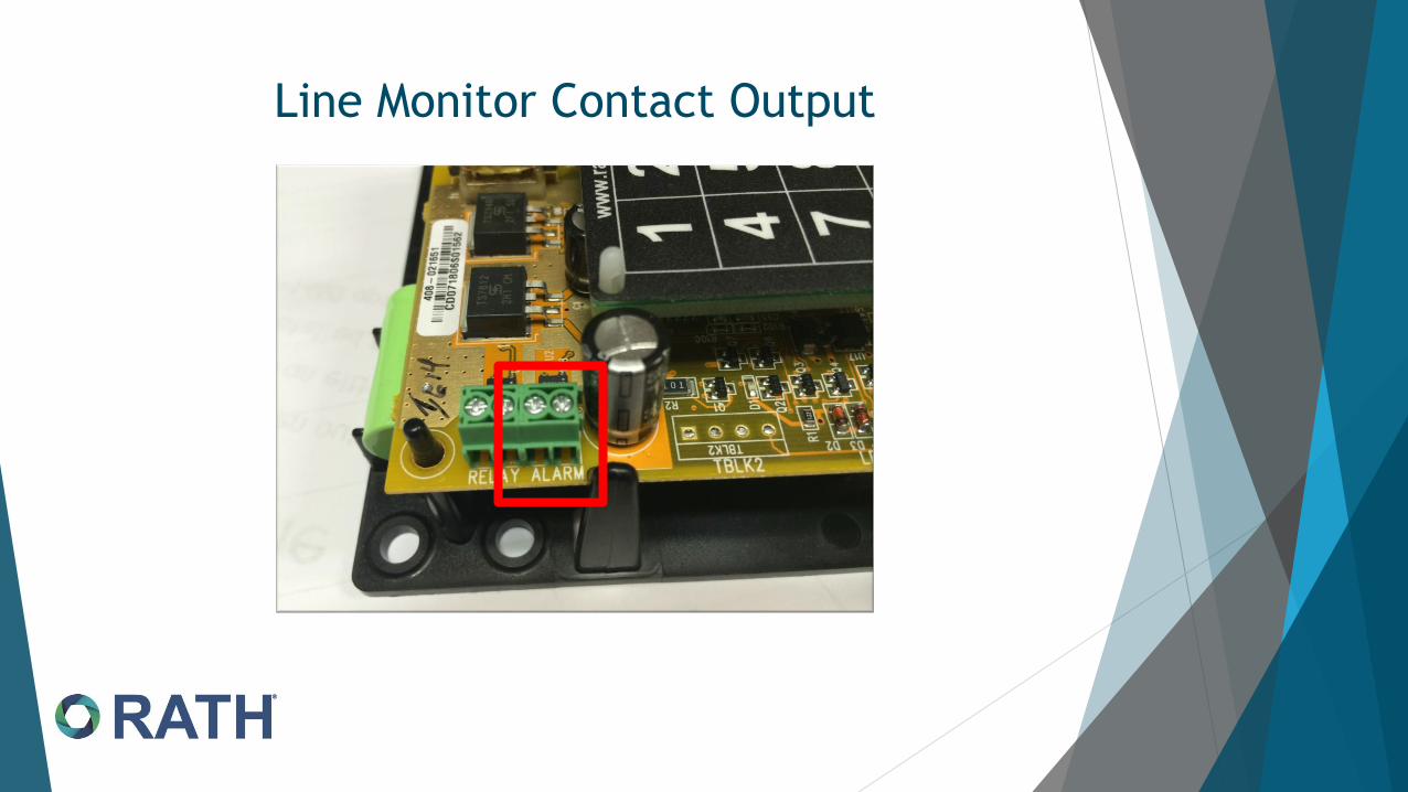
Line Monitor Contact Output

Endpoint will not call out or, may be able to call from SmartRescue to endpoint, but not from the endpoint to SmartRescue or LED on front of endpoint, will come on, then go off, and not call out
▪ If 4 wires not running all the way through or compromised in some way
▪ No outside phone line connected, or is not active
Call not stopping at SmartRescue, and calling out right away
▪ SmartRescue not programmed properly, or not programmed at all
▪ Call placed before timer reset.
Lights on front of SmartRescue blinking and beeping coming from buzzer periodically
▪ Endpoints have built in line check, where they are checking for dial tone and voltage, this is a part of code requirements in some states
Troubleshooting

Recap and
Question Time
Two sizes of SmartRescue
Units can be programmed to call Base, then out or
outside only
Up to two Sub-Masters may be installed on either size
system
All prerequisites MUST be properly installed for system
to function
Call RATH® Tech Support at 1-800-451-1460 option 3 for
assistance

Command
Center

Command Center
Overview
Typically used for applications
requiring greater than 10 endpoints
Used with either RATH® 2400 (2100
Series Endpoints can beaded as
needed)
Station Supervisor available for use
with 2400 series Endpoints
Must have 110/120VAC Power Source
Optional add on Sub-Master Stations
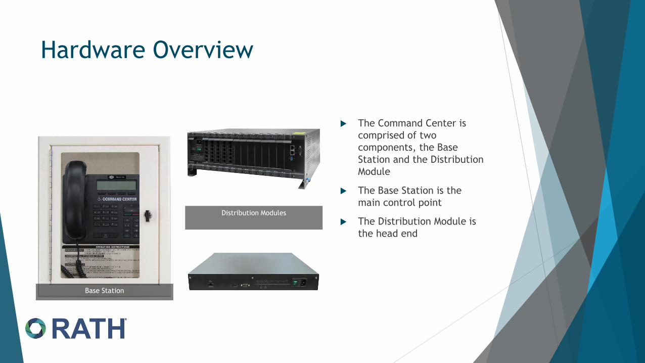
Hardware Overview
The Command Center is
comprised of two
components, the Base
Station and the Distribution
Module
The Base Station is the
main control point
The Distribution Module is
the head end
Base Station
Distribution Modules
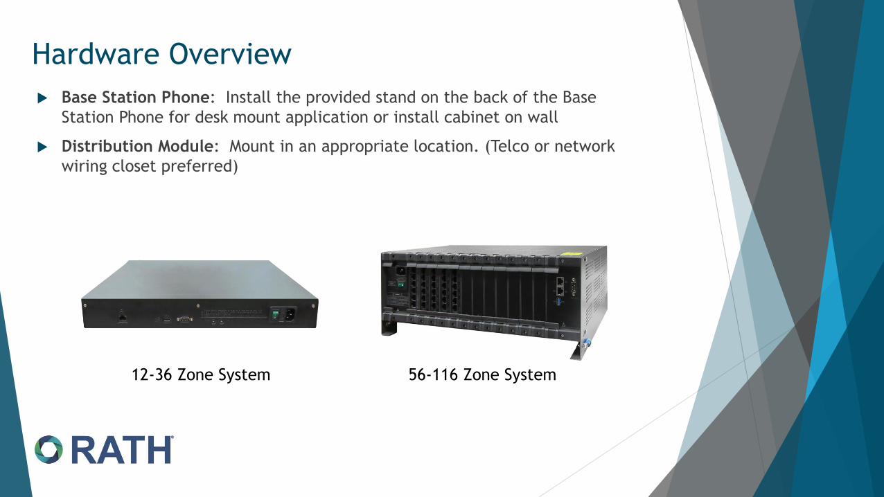
Base Station Phone: Install the provided stand on the back of the Base
Station Phone for desk mount application or install cabinet on wall
Distribution Module: Mount in an appropriate location. (Telco or network
wiring closet preferred)
12-36 Zone System 56-116 Zone System
Hardware Overview

Hardware Installation- EndpointsFollow recommended installation for type of endpoints installed with system
Cut the end off of the provided phone cable and
direct splice the wires to feeder cable
Scotch lock or use “dolphin” connectors directly on
line cordsDO NOT
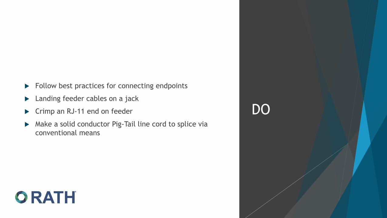
Follow best practices for connecting endpoints
Landing feeder cables on a jack
Crimp an RJ-11 end on feeder
Make a solid conductor Pig-Tail line cord to splice via
conventional means
DO

Pre-Installation
Requirements
110/120VAC Power
Twisted, shielded, solid conductor 24
or 22 gauge, single pair cabling
between Distribution Module and
Devices
Analog Telephone Line (POTS, PBX, or
Central Office)-Optional

Hardware Installation for 12-36 Zone System
Each Circuit Card has 3 RJ-45 style connectors
NOTE:(From left to right) the port counts on each
connector are 4-2-2, for 8 ports per card
Connect provided “pig-tailed” cables to card RJ-45
ports and extend wire pairs to desired device
If 4 ports, use all 4 pair from the provided cable
Blue, Orange, Green, Brown
If 2 ports use only the Blue and Orange pairs
If making replacement cables, use T-568A pin out
*Specific port identification and wiring specifications will be discussed in 2 slides

Hardware Installation for 12-36 Zone System
Connecting Base Station to Distribution Module:
▪ Identify DKP Port top of the first card (closest to power supply)
Maximum Wire Run Length is: 1000’ to Command Center
Connecting Endpoints to Distribution Module:
▪ Locate table on top of circuit cards and identify “SLT” Ports
Maximum Wire Run Length is: 4000’ to Endpoint
The Command Center does not need an outside phone line, unless there is a requirement for the system to call an outside party
▪ If connecting outside line, locate the “TWT” port on the first card and connect phone line to the blue, blue-white pair

12-36 Zone Card Wiring Overview

12-36 Zone Card Wiring Overview

Hardware
Installation for 56 -
116 Zone System
Each Circuit Card has 20 ports across 6 RJ-45 style connectors
NOTE:(From top to bottom) the port counts are 4-4-4-4-2-2
Connect provided “pig-tailed” cables to ports and connect wiring to desired device
If 4 ports, use all 4 pair from the provided cable. Blue, Orange, Green, Brown
If 2 ports Use only the Blue and Orange pairs
If making replacement cables, use T-568A pin out

Hardware
Installation for 56-
116 Zone System
Connecting Base Station to Distribution Module:
▪ Identify DKP Port (card closest to power supply) with the dot in the D and 1-2
Connecting endpoints to Distribution Module:
▪ Locate “SLT” ports on cards, they will be labeled with Sxx-Sxx
The Command Center does not need an outside phone line, unless there is a requirement for the system to call an outside party
▪ If an outside phone line is required, on the first card beginning from left, locate the port labeled “T,D, 1-2,3-4” that has the white dot under the “T”. This is outside line connection.
If making replacement cables, use T-568A pin out

56-116 Zone Card Wiring Overview

56-116 Zone Card Wiring Overview

Programming Date/Time Display
Program Time Zone:
▪ Enter Programming
o Lift Handset, Dial 1, #, 9, 1
o Enter Passcode: 7, 2, 8, 4
▪ Dial 1, 0, 0, 2
▪ Enter Correct Time Zone Code:
o Eastern: 1, 1, 1
o Central: 1, 1, 2
o Mountain: 1, 1, 3
o Pacific: 1, 1, 4
▪ Touch Check Mark Button under display
Dial 0, 0 and touch check mark button again
▪ Dial 0, 0 and touch check mark
Program Month, Day, and Year
▪ Enter Programming
o Lift Handset, Dial 1, #, 9, 1
o Enter Passcode: 7, 2, 8, 4
▪ Dial 1, 0, 0, 1 (Month-Day- Year)- [Ex: 02152011 (Feb. 15, 2011)]
▪ Touch Check Mark Under Display
Dial 0, 0 and touch check mark
Program Time:
▪ Enter Programming
o Lift Handset, Dial 1, #, 9, 1
o Enter Passcode: 7, 2, 8, 4
▪ Dial 1, 0, 0, 3 (Hours- Min- Sec) [Ex: 143000 (2:30 p.m.)
▪ Touch Check Mark
The Base Station phone has the date and time displayed on the screen. After powering on the
system, if the correct information is displayed, proceed in programming the endpoints. If the
information is incorrect, perform the following:

Programming Endpoints
Endpoints call to call sequencer, program
3931 in memory slot 1
First attempt is to Command Center
If no answer, call is forwarded to outside
number
Number is programmed at Command Center
Dial 1, 3, 4, 9, outside number, #, *
Subsequent unanswered calls go back to
sequencer if line is unavailable

Programming Endpoints (continued)
Program location specific message
*Note – With 2400 sets only use
the continuous play until
interrupted by called Party (7*3)
Message must end with the
phrase “For 2-way
communications press the # key
4 times after the beep”

Base Station Operation

Required in most areas
NO additional wire pair to endpoints
Supervisor can provide either normally open or closed
contact
Monitors phone line and endpoints (Base not required)
Connection to additional device for notification
required
System
Supervision
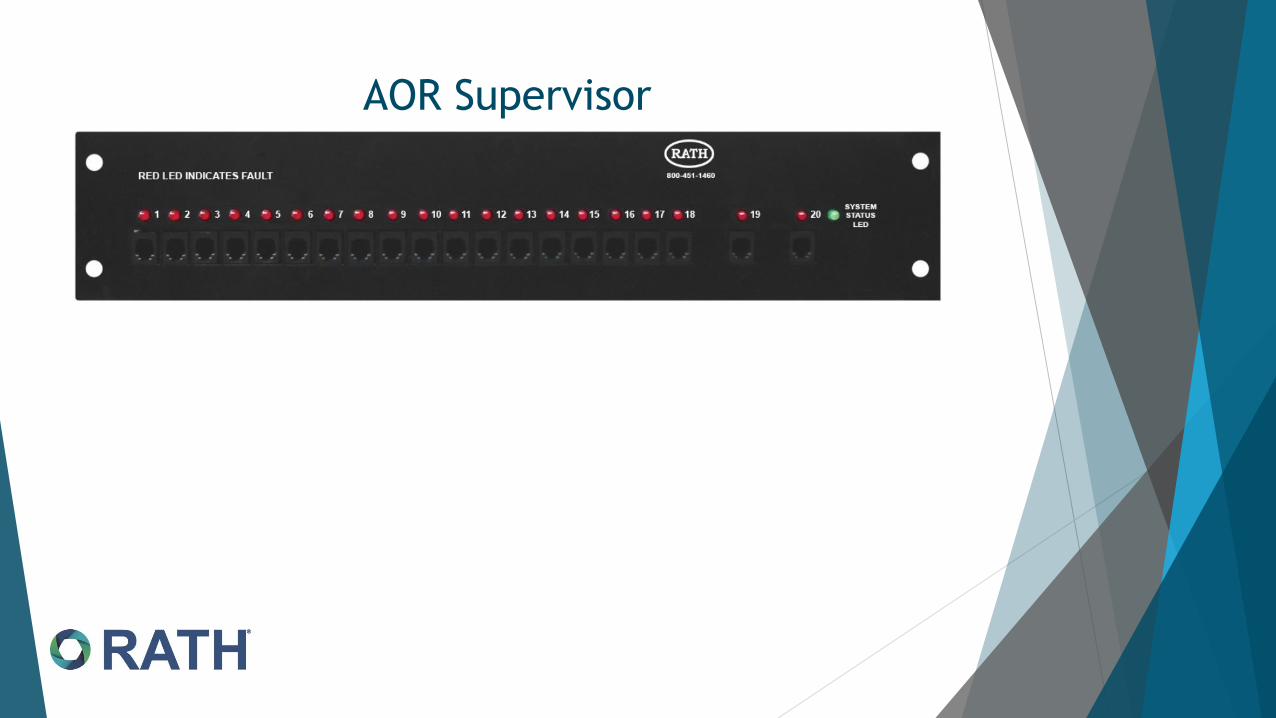
AOR Supervisor

Supervisor Board Connections

Supervisor Board Connections

Wiring Connections

Alert Device Connection

Power
Connection

Command Center Distribution Module has 2 sizes
depending on number of endpoints
Follow wiring diagram(s) for proper connections
Can use either 2100 or 2400 series endpoints
Can be equipped with multiple Sub-Masters
Supervision of all connections done with 2400
endpoints via Supervisor Board
Questions/Recap:

Jerry LastJerry Last, TCI
Rath Communications
N56 W24720 N. Corporate Circle
Sussex, WI 53089
800-451-1460
This is to Certify that
Has completed the prescribed course for Certified Emergency Communication Systems Installer –Analog
During the Year of 2020