RapidEye Image Product Specifications - Gisat / cz DEM Digital Elevation Model DTED Digital Terrain...
22
RapidEye ™ Image Product Specifications April 2007 Contact: RapidEye AG Molkenmarkt 30 14776 Brandenburg an der Havel Germany Phone: +49 3381 8904-555 Fax: +49 3381 8904-101 Toll Free (US): +1 800 940 3617 Email: [email protected] Web: www.rapideye.de
Transcript of RapidEye Image Product Specifications - Gisat / cz DEM Digital Elevation Model DTED Digital Terrain...
RapidEye™ Image Product Specifications
April 2007
Contact: RapidEye AGMolkenmarkt 3014776 Brandenburg an der HavelGermany
Phone: +49 3381 8904-555Fax: +49 3381 8904-101Toll Free (US): +1 800 940 3617Email: [email protected]: www.rapideye.de

Table of Contents
INTRODUCTION....................................................................................................................................................5
RAPIDEYE IMAGE PRODUCTS...........................................................................................................................6
SENSOR-LEVEL PRODUCT SPECIFICATIONS.................................................................................................6
GEO-CORRECTED AND ORTHO-CORRECTED PRODUCT SPECIFICATIONS..............................................8
PROCESSING OPTIONS.......................................................................................................................................9
APPENDIX A – GLOSSARY OF TERMS............................................................................................................10
APPENDIX B – TILE GRID DEFINITION............................................................................................................12
APPENDIX C – ATMOSPHERIC CORRECTION ...............................................................................................15
APPENDIX D – IMAGE SUPPORT DATA..........................................................................................................16
RapidEye Proprietary Information
Page 2 of 22
Index of TablesTable 1: RapidEye System Specifications...........................................................................................5Table 2: RapidEye Image Processing Levels......................................................................................6Table 3: Product attributes for sensor-level products.........................................................................7Table 4: Attributes for Geo-corrected Products...................................................................................8Table 5: Processing Options................................................................................................................9
RapidEye Proprietary Information
Page 3 of 22
Abbreviations
DEM Digital Elevation Model
DTED Digital Terrain Elevation Data
GCP Ground Control Point
GS Ground Segment
JFIF JPEG File Interchange Format
JPEG Joint Photographic Experts Group
IFOV Instantaneous Field of View
MTF Modulation Transfer Function
N/A Not Applicable
NITF National Imagery Transmission Format
TBC To Be Confirmed
TBD To Be Defined
TIFF Tagged Image File Format
UDM Unusable Data Mask
UTM Universal Transverse Mercator
WGS World Geodetic System
RapidEye Proprietary Information
Page 4 of 22
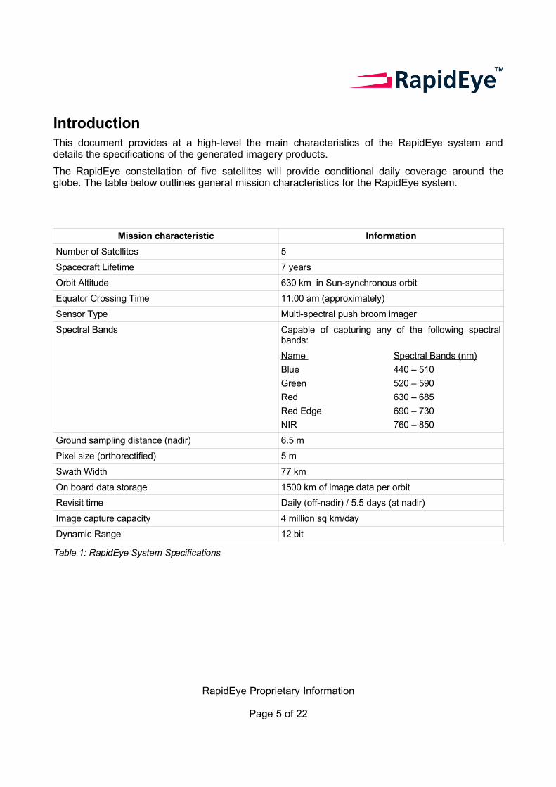
IntroductionThis document provides at a high-level the main characteristics of the RapidEye system and details the specifications of the generated imagery products.
The RapidEye constellation of five satellites will provide conditional daily coverage around the globe. The table below outlines general mission characteristics for the RapidEye system.
Mission characteristic Information
Number of Satellites 5
Spacecraft Lifetime 7 years
Orbit Altitude 630 km in Sun-synchronous orbit
Equator Crossing Time 11:00 am (approximately)
Sensor Type Multi-spectral push broom imager
Spectral Bands Capable of capturing any of the following spectral bands:
Name
Blue
Green
Red
Red Edge
NIR
Spectral Bands (nm)
440 – 510
520 – 590
630 – 685
690 – 730
760 – 850
Ground sampling distance (nadir) 6.5 m
Pixel size (orthorectified) 5 m
Swath Width 77 km
On board data storage 1500 km of image data per orbit
Revisit time Daily (off-nadir) / 5.5 days (at nadir)
Image capture capacity 4 million sq km/day
Dynamic Range 12 bit
Table 1: RapidEye System Specifications
RapidEye Proprietary Information
Page 5 of 22
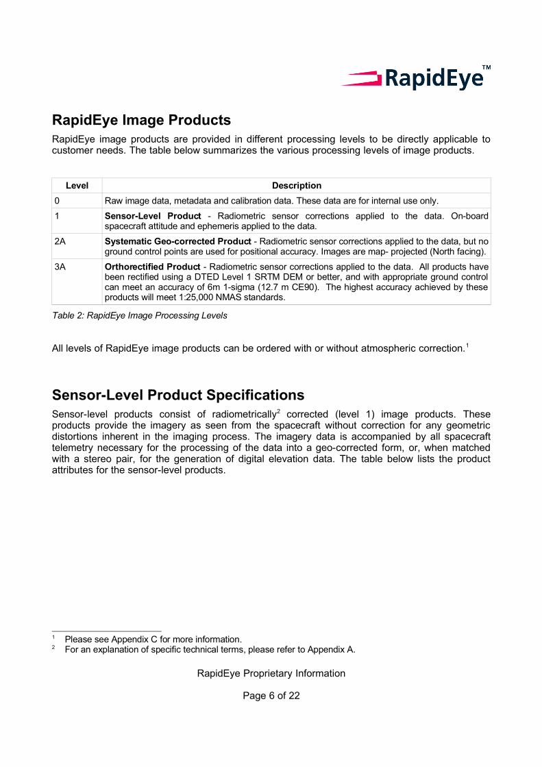
RapidEye Image ProductsRapidEye image products are provided in different processing levels to be directly applicable to customer needs. The table below summarizes the various processing levels of image products.
Level Description
0 Raw image data, metadata and calibration data. These data are for internal use only.
1 Sensor-Level Product - Radiometric sensor corrections applied to the data. On-board spacecraft attitude and ephemeris applied to the data.
2A Systematic Geo-corrected Product - Radiometric sensor corrections applied to the data, but no ground control points are used for positional accuracy. Images are map- projected (North facing).
3A Orthorectified Product - Radiometric sensor corrections applied to the data. All products have been rectified using a DTED Level 1 SRTM DEM or better, and with appropriate ground control can meet an accuracy of 6m 1-sigma (12.7 m CE90). The highest accuracy achieved by these products will meet 1:25,000 NMAS standards.
Table 2: RapidEye Image Processing Levels
All levels of RapidEye image products can be ordered with or without atmospheric correction.1
Sensor-Level Product SpecificationsSensor-level products consist of radiometrically2 corrected (level 1) image products. These products provide the imagery as seen from the spacecraft without correction for any geometric distortions inherent in the imaging process. The imagery data is accompanied by all spacecraft telemetry necessary for the processing of the data into a geo-corrected form, or, when matched with a stereo pair, for the generation of digital elevation data. The table below lists the product attributes for the sensor-level products.
1 Please see Appendix C for more information.2 For an explanation of specific technical terms, please refer to Appendix A.
RapidEye Proprietary Information
Page 6 of 22
Product Attribute DescriptionProduct Components and Format
Sensor-level image product consists of the following physical components:
- Image File(s) – Each file contains the image data for one spectral band and some basic image metadata. Delivered as NITF.
- Metadata File – XML format metadata file containing product metadata, spacecraft attitude, spacecraft position/velocity, spacecraft temperature measurements, line imaging times, radiometric calibration data.
- Browse image in JFIF format
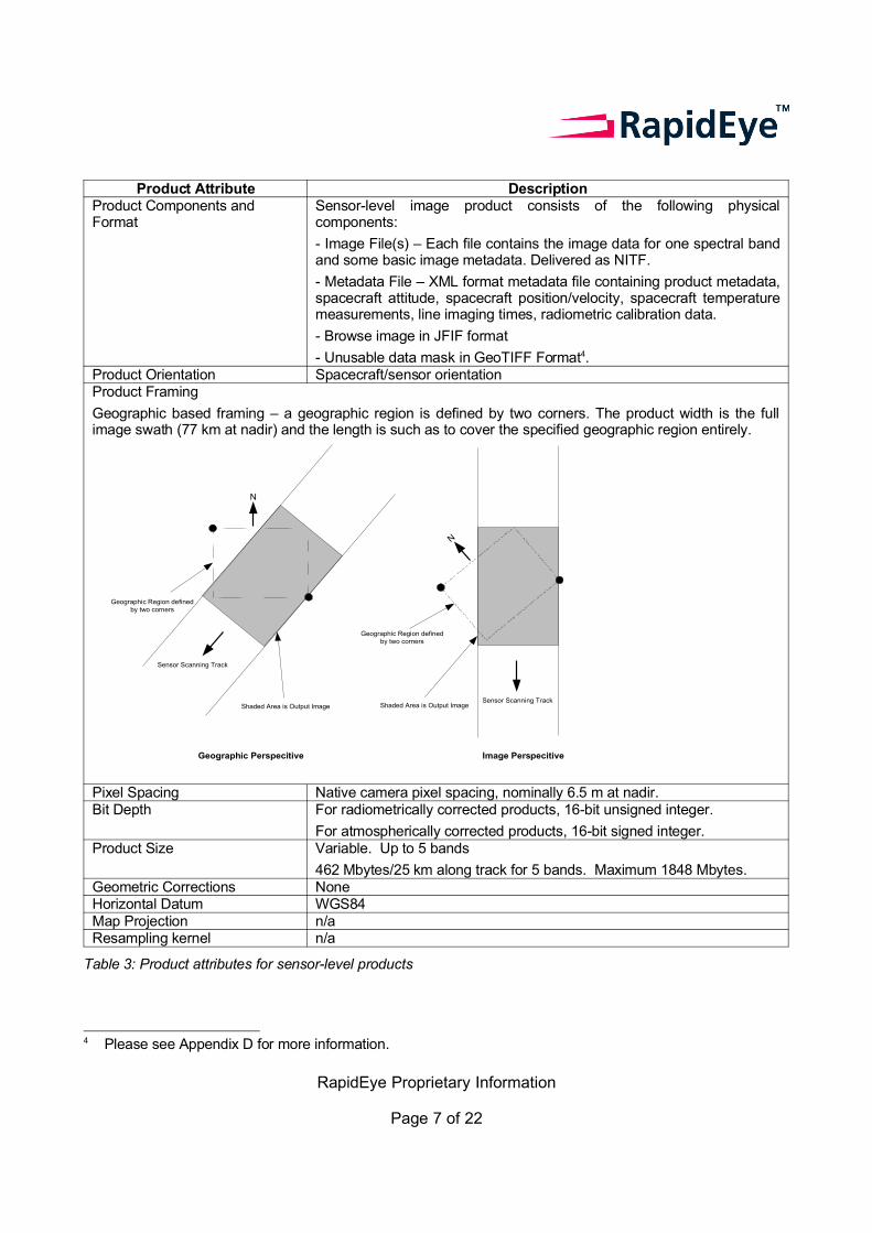
- Unusable data mask in GeoTIFF Format4.Product Orientation Spacecraft/sensor orientationProduct Framing
Geographic based framing – a geographic region is defined by two corners. The product width is the full image swath (77 km at nadir) and the length is such as to cover the specified geographic region entirely.
N
Sensor Scanning Track
N
Shaded Area is Output ImageSensor Scanning Track
Geographic Perspecitive Image Perspecitive
Geographic Region definedby two corners
Shaded Area is Output Image
Geographic Region definedby two corners
Pixel Spacing Native camera pixel spacing, nominally 6.5 m at nadir. Bit Depth For radiometrically corrected products, 16-bit unsigned integer.
For atmospherically corrected products, 16-bit signed integer.Product Size Variable. Up to 5 bands
462 Mbytes/25 km along track for 5 bands. Maximum 1848 Mbytes.Geometric Corrections None Horizontal Datum WGS84Map Projection n/aResampling kernel n/a
Table 3: Product attributes for sensor-level products
4 Please see Appendix D for more information.
RapidEye Proprietary Information
Page 7 of 22
Geo-corrected and Ortho-corrected Product Specifications
Geo-corrected products comprising level 2 and 3 products are radiometrically corrected to a standard radiance or reflectance scale, and are geometrically aligned to a map projection. The processing levels of products differ in the amount of geometric correction that is applied to them:
• Systematic Geo-corrected products (level 2A) are corrected using spacecraft derived data only with a course DEM applied but no GCPs are used. Geo-corrected image products are output as UTM tiles in the standard RapidEye image tile grid system.
• Orthorectified products (level 3A) offer the highest level of processing available in the RapidEye system with a DEM and GCPs being used to correct the image. Orthorectified image products are output as UTM tiles in the standard RapidEye image tile grid system.
The table below lists the attributes for the Geo-corrected products.
Product Attribute DescriptionProduct Components and Format
Geo-corrected image product consists of the following physical components:
• Image File – GeoTIFF file that contains image data and geolocation information
• Metadata File – XML format metadata file
• Browse Image – JFIF format
• Unusable Data Mask – GeoTIFF FormatProduct Orientation Map North up Product Framing Image Tile (image tiles are based on a worldwide, 24km by 24km fixed grid
system (see Appendix B for full tile grid definition). To each 24km by 24km grid square a 500m overlap is added to produce a 25km by 25km image tile. Image tiles that are only partially covered by an image take will be black-filled in areas with no data.)
Pixel Spacing 5mBit Depth • For radiometrically corrected products, 16-bit unsigned integers.
• For atmospherically corrected products, 16-bit signed integers.Product Size Tile size is 25km by 25km. 250 Mbytes/Tile for 5 bands at 5m pixel spacing,
plus a small amount for the metadata file, the browse image file and the unusable data mask file.
Geometric Corrections • Sensor-related effects are corrected using sensor telemetry and a sensor model, bands are co-registered, and spacecraft-related effects are corrected using attitude telemetry and best available ephemeris data for all Level 2 and 3 products.
• Ortho-rectified using GCPs and DEMs (level 3A )Horizontal Datum WGS84Map Projection Universal Transverse MercatorResampling Kernel Cubic Convolution (default); or MTF
Table 4: Attributes for Geo-corrected Products
RapidEye Proprietary Information
Page 8 of 22

Processing OptionsThe table below summarizes the processing options available for all level 1 through level 3A products.
Processing Option Discussion
Atmospheric Correction
(see Appendix C for more information)
The ATCOR 3 atmospheric correction algorithm can be applied to all product levels.
For atmospherically corrected products:
• Corrected from at-aperture radiance to at-surface reflectance
• Output digital numbers can be converted to reflectance units using the scaling factors provided in the metadata.
Processing Kernel
(for Levels 2A and 3A only)
MTF or Cubic Convolution (default)
Delivery Format • GeoTIFF (default for levels 2A and 3A );
• NITF (default for level 1);
• customer specified.
Projection UTM (standard) or customer specified
Table 5: Processing Options
RapidEye Proprietary Information
Page 9 of 22
Appendix A – Glossary of TermsThe following list defines terms used to describe RapidEye image products.
Bidirectional ReflectanceDistribution Function (BRDF)
• Describes the directional dependence of reflected energy (light). BRDF is a fundamental optical property. It characterizes the energy scattered into the hemisphere above a surface as a result of incident radiation.
Digital Elevation Model (DEM) • A digital model of the terrain surface, usually derived from stereo imagery. A DEM is used to remove terrain distortions from the imagery for the geo-corrected products.
Digital Number (DN) • The value assigned to a pixel in a digital image. This gray density value represents the intensity of reflected light from a feature collected by the sensor for a particular spectral range.
Dynamic Range • The number of possible DN values for each pixel in a band of an image. RapidEye has an 12-bit dynamic range which translates into 4096 possible values.
Ground Control Point (GCP) • A visible point on the ground with known geographic coordinates. GCPs can be planimetric (latitude, longitude) or vertical (latitude, longitude, elevation). GCPs can be collected from a ground survey, maps, or orthorectified imagery.
Ground Sample Distance (GSD) • The size of one pixel, as measured on the ground.
Instantaneous Field of View (IFOV)
• The area on the ground visible to the satellite.
Metadata • Ancillary data that describes and defines the RapidEye imagery product. Metadata files differ for the two image processing types. See Appendix C for a complete breakdown of metadata files and the fields within them.
Nadir • The point on the ground that is directly below the satellite.
Off-nadir Angle • The angle between nadir and the point on the ground that the satellite is pointing to.
Orthorectification • The correction of distortions caused by terrain relief displacement on the image.
Pixel • The smallest element comprising a digital image.
Radiometric Correction • The correction of variations in data that are not caused by the object or scene being scanned. These include non-
RapidEye Proprietary Information
Page 10 of 22
responsive detectors and scanner inconsistencies.
Resolution • The resampled image pixel size derived from the GSD.
Revisit Time • The amount of time it takes to image the same point on the ground.
Sensor Correction • The correction of variations in the data that are caused by sensor geometry, attitude and ephemeris.
Sun Azimuth • The azimuth of the sun as seen by an observer located at the target point, measured in a clockwise direction from the North.
Sun Elevation • The angle of the sun above the horizon.
Sun-Synchronous • An orbit which rotates around the Earth at the same rate as the Earth rotates on its axis.
Swath Width • The width of the ground area that is recorded by one image strip.
Terrain Correction • The correction for variations in data caused by terrain displacement due to off-nadir viewing.
RapidEye Proprietary Information
Page 11 of 22
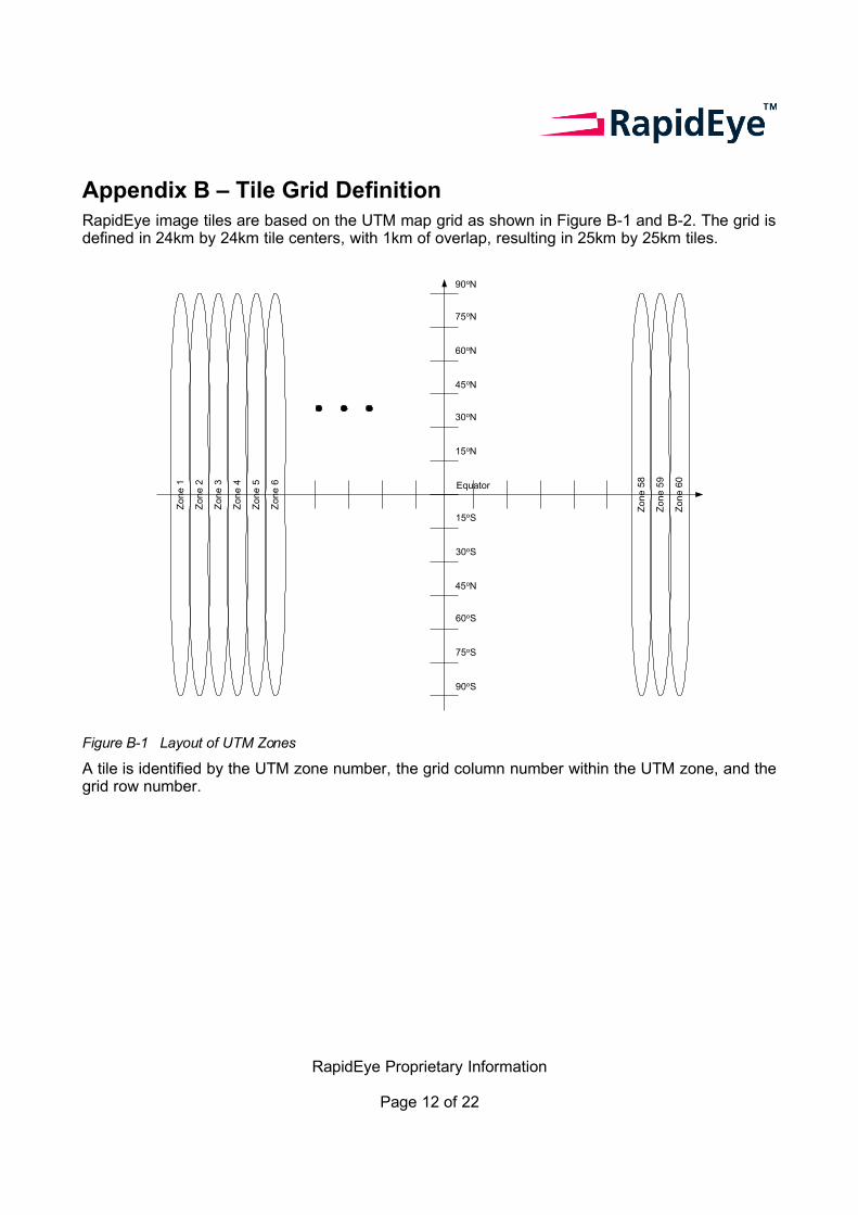
Appendix B – Tile Grid DefinitionRapidEye image tiles are based on the UTM map grid as shown in Figure B-1 and B-2. The grid is defined in 24km by 24km tile centers, with 1km of overlap, resulting in 25km by 25km tiles.
Zo
ne
1
Zo
ne
2
Zo
ne
3
Zo
ne
4
Zo
ne
58
Zo
ne
59
Zo
ne
60
Zo
ne
5
Zo
ne
6 Equator
90oN
75oN
60oN
45oN
30oN
15oN
15oS
30oS
45oN
60oS
75oS
90oS
Figure B-1 Layout of UTM Zones
A tile is identified by the UTM zone number, the grid column number within the UTM zone, and the grid row number.
RapidEye Proprietary Information
Page 12 of 22
Column 1 Column 14 Column 15 Column 28
Row
1R
ow 390
Row
391R
ow 780
6o
~84
o~
84o
6o
6o
Tiles Overlapsfrom Zone to Zone
Zone Boundary(+/-3o Longitude)
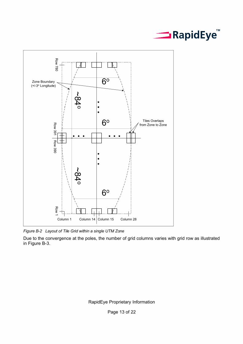
Figure B-2 Layout of Tile Grid within a single UTM Zone
Due to the convergence at the poles, the number of grid columns varies with grid row as illustrated in Figure B-3.
RapidEye Proprietary Information
Page 13 of 22
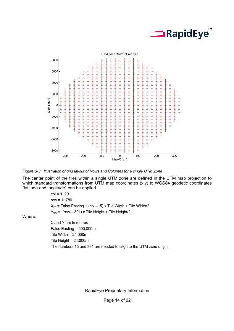
Figure B-3 Illustration of grid layout of Rows and Columns for a single UTM Zone
The center point of the tiles within a single UTM zone are defined in the UTM map projection to which standard transformations from UTM map coordinates (x,y) to WGS84 geodetic coordinates (latitude and longitude) can be applied.
col = 1..29
row = 1..780
Xcol = False Easting + (col –15) x Tile Width + Tile Width/2
Yrow = (row – 391) x Tile Height + Tile Height/2Where:
X and Y are in metres
False Easting = 500,000m
Tile Width = 24,000m
Tile Height = 24,000m
The numbers 15 and 391 are needed to align to the UTM zone origin.
RapidEye Proprietary Information
Page 14 of 22
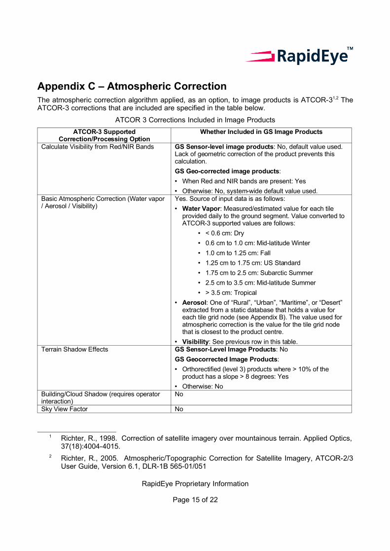
Appendix C – Atmospheric Correction The atmospheric correction algorithm applied, as an option, to image products is ATCOR-31,2 The ATCOR-3 corrections that are included are specified in the table below.
ATCOR 3 Corrections Included in Image Products
ATCOR-3 Supported Correction/Processing Option
Whether Included in GS Image Products
Calculate Visibility from Red/NIR Bands GS Sensor-level image products: No, default value used. Lack of geometric correction of the product prevents this calculation.
GS Geo-corrected image products:
• When Red and NIR bands are present: Yes
• Otherwise: No, system-wide default value used. Basic Atmospheric Correction (Water vapor / Aerosol / Visibility)
Yes. Source of input data is as follows:
• Water Vapor: Measured/estimated value for each tile provided daily to the ground segment. Value converted to ATCOR-3 supported values are follows:
• < 0.6 cm: Dry
• 0.6 cm to 1.0 cm: Mid-latitude Winter
• 1.0 cm to 1.25 cm: Fall
• 1.25 cm to 1.75 cm: US Standard
• 1.75 cm to 2.5 cm: Subarctic Summer
• 2.5 cm to 3.5 cm: Mid-latitude Summer
• > 3.5 cm: Tropical
• Aerosol: One of “Rural”, “Urban”, “Maritime”, or “Desert” extracted from a static database that holds a value for each tile grid node (see Appendix B). The value used for atmospheric correction is the value for the tile grid node that is closest to the product centre.
• Visibility: See previous row in this table.Terrain Shadow Effects GS Sensor-Level Image Products: No
GS Geocorrected Image Products:
• Orthorectified (level 3) products where > 10% of the product has a slope > 8 degrees: Yes
• Otherwise: No Building/Cloud Shadow (requires operator interaction)
No
Sky View Factor No
1 Richter, R., 1998. Correction of satellite imagery over mountainous terrain. Applied Optics, 37(18):4004-4015.
2 Richter, R., 2005. Atmospheric/Topographic Correction for Satellite Imagery, ATCOR-2/3 User Guide, Version 6.1, DLR-1B 565-01/051
RapidEye Proprietary Information
Page 15 of 22
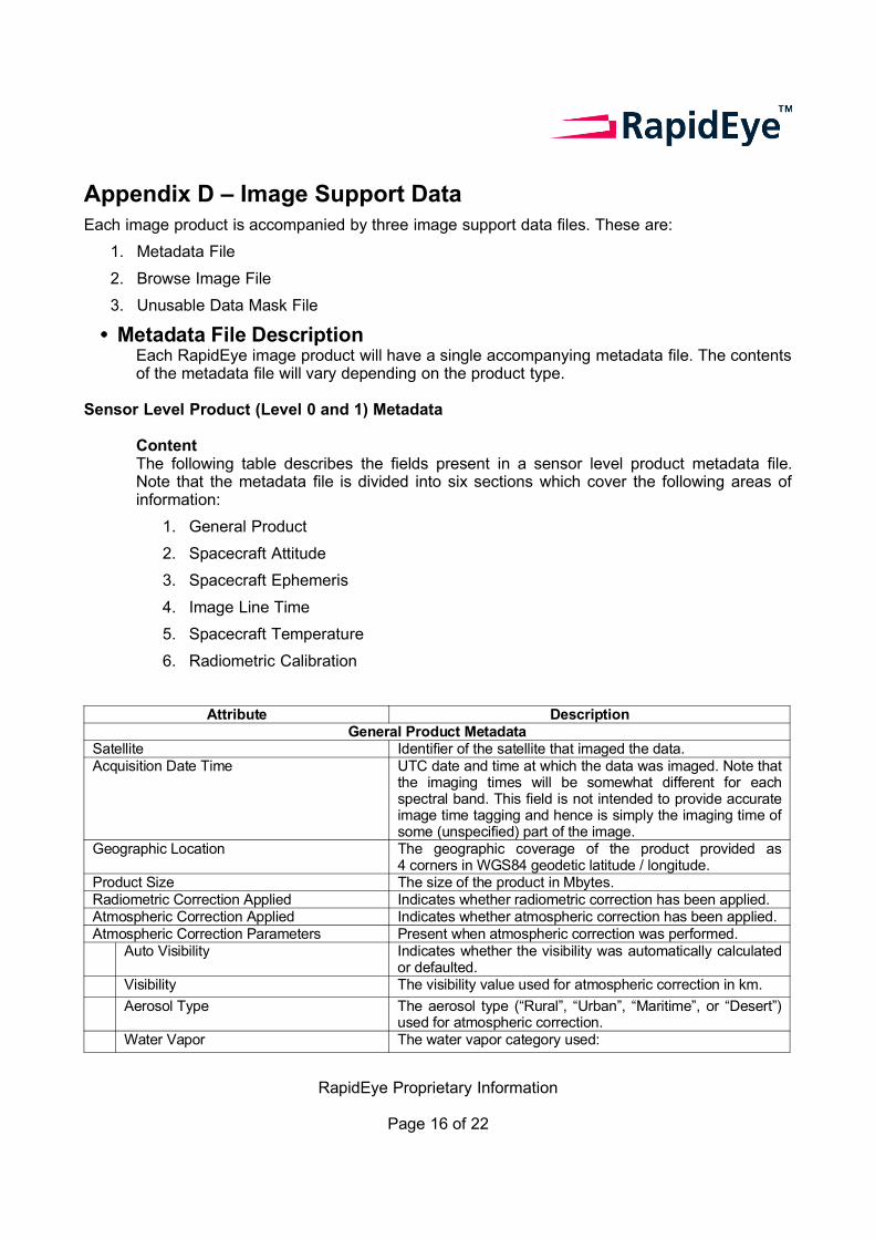
Appendix D – Image Support DataEach image product is accompanied by three image support data files. These are:
1. Metadata File
2. Browse Image File
3. Unusable Data Mask File
• Metadata File DescriptionEach RapidEye image product will have a single accompanying metadata file. The contents of the metadata file will vary depending on the product type.
Sensor Level Product (Level 0 and 1) Metadata
ContentThe following table describes the fields present in a sensor level product metadata file. Note that the metadata file is divided into six sections which cover the following areas of information:
1. General Product
2. Spacecraft Attitude
3. Spacecraft Ephemeris
4. Image Line Time
5. Spacecraft Temperature
6. Radiometric Calibration
Attribute DescriptionGeneral Product Metadata
Satellite Identifier of the satellite that imaged the data.Acquisition Date Time UTC date and time at which the data was imaged. Note that
the imaging times will be somewhat different for each spectral band. This field is not intended to provide accurate image time tagging and hence is simply the imaging time of some (unspecified) part of the image.
Geographic Location The geographic coverage of the product provided as 4 corners in WGS84 geodetic latitude / longitude.
Product Size The size of the product in Mbytes.Radiometric Correction Applied Indicates whether radiometric correction has been applied.Atmospheric Correction Applied Indicates whether atmospheric correction has been applied.Atmospheric Correction Parameters Present when atmospheric correction was performed.
Auto Visibility Indicates whether the visibility was automatically calculated or defaulted.
Visibility The visibility value used for atmospheric correction in km.
Aerosol Type The aerosol type (“Rural”, “Urban”, “Maritime”, or “Desert”) used for atmospheric correction.
Water Vapor The water vapor category used:
RapidEye Proprietary Information
Page 16 of 22
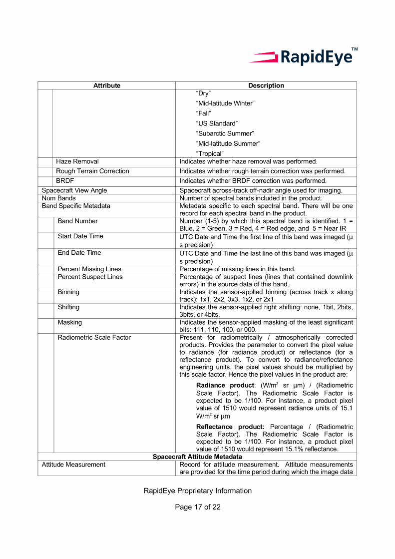
Attribute Description“Dry”
“Mid-latitude Winter”
“Fall”
“US Standard”
“Subarctic Summer”
“Mid-latitude Summer”
“Tropical”Haze Removal Indicates whether haze removal was performed.
Rough Terrain Correction Indicates whether rough terrain correction was performed.
BRDF Indicates whether BRDF correction was performed.
Spacecraft View Angle Spacecraft across-track off-nadir angle used for imaging.Num Bands Number of spectral bands included in the product.Band Specific Metadata Metadata specific to each spectral band. There will be one
record for each spectral band in the product.Band Number Number (1-5) by which this spectral band is identified. 1 =
Blue, 2 = Green, 3 = Red, 4 = Red edge, and 5 = Near IRStart Date Time UTC Date and Time the first line of this band was imaged (µ
s precision)End Date Time UTC Date and Time the last line of this band was imaged (µ
s precision)Percent Missing Lines Percentage of missing lines in this band.Percent Suspect Lines Percentage of suspect lines (lines that contained downlink
errors) in the source data of this band.Binning Indicates the sensor-applied binning (across track x along
track): 1x1, 2x2, 3x3, 1x2, or 2x1Shifting Indicates the sensor-applied right shifting: none, 1bit, 2bits,
3bits, or 4bits.Masking Indicates the sensor-applied masking of the least significant
bits: 111, 110, 100, or 000.Radiometric Scale Factor Present for radiometrically / atmospherically corrected
products. Provides the parameter to convert the pixel value to radiance (for radiance product) or reflectance (for a reflectance product). To convert to radiance/reflectance engineering units, the pixel values should be multiplied by this scale factor. Hence the pixel values in the product are:
Radiance product: (W/m2 sr µm) / (Radiometric Scale Factor). The Radiometric Scale Factor is expected to be 1/100. For instance, a product pixel value of 1510 would represent radiance units of 15.1 W/m2 sr µm
Reflectance product: Percentage / (Radiometric Scale Factor). The Radiometric Scale Factor is expected to be 1/100. For instance, a product pixel value of 1510 would represent 15.1% reflectance.
Spacecraft Attitude MetadataAttitude Measurement Record for attitude measurement. Attitude measurements
are provided for the time period during which the image data
RapidEye Proprietary Information
Page 17 of 22
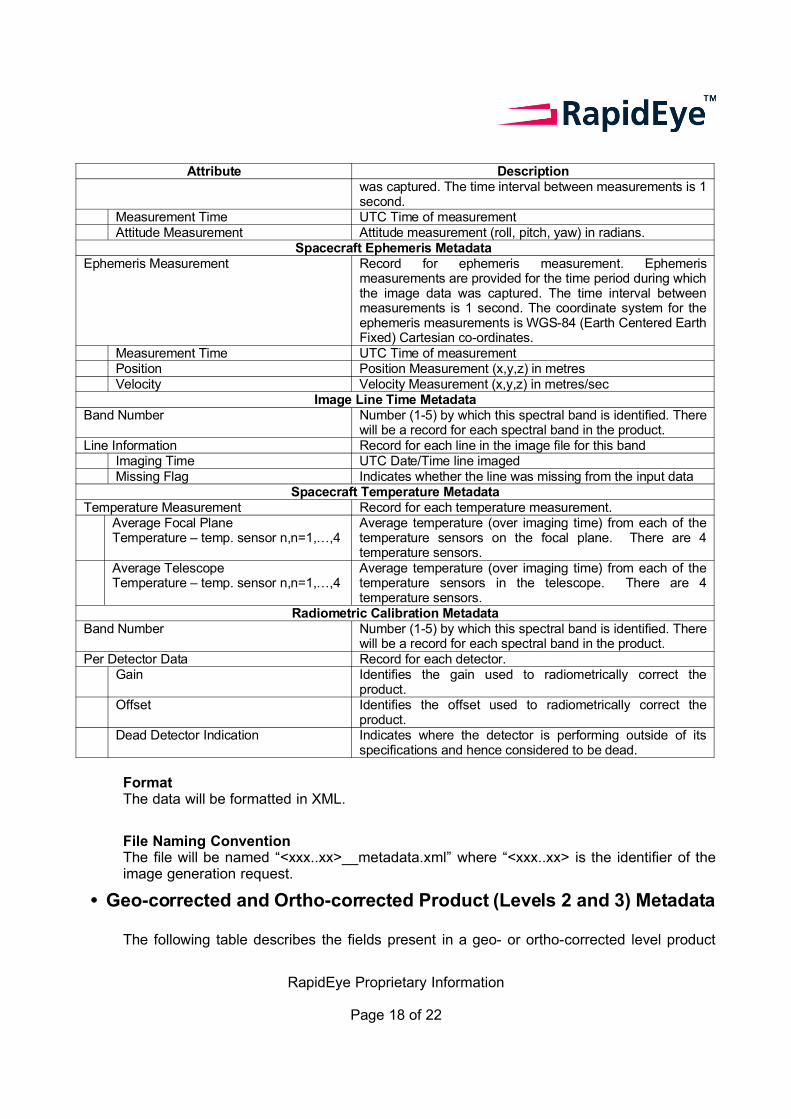
Attribute Descriptionwas captured. The time interval between measurements is 1 second.
Measurement Time UTC Time of measurementAttitude Measurement Attitude measurement (roll, pitch, yaw) in radians.
Spacecraft Ephemeris Metadata Ephemeris Measurement Record for ephemeris measurement. Ephemeris
measurements are provided for the time period during which the image data was captured. The time interval between measurements is 1 second. The coordinate system for the ephemeris measurements is WGS-84 (Earth Centered Earth Fixed) Cartesian co-ordinates.
Measurement Time UTC Time of measurementPosition Position Measurement (x,y,z) in metresVelocity Velocity Measurement (x,y,z) in metres/sec
Image Line Time MetadataBand Number Number (1-5) by which this spectral band is identified. There
will be a record for each spectral band in the product.Line Information Record for each line in the image file for this band
Imaging Time UTC Date/Time line imagedMissing Flag Indicates whether the line was missing from the input data
Spacecraft Temperature MetadataTemperature Measurement Record for each temperature measurement.
Average Focal Plane Temperature – temp. sensor n,n=1,…,4
Average temperature (over imaging time) from each of the temperature sensors on the focal plane. There are 4 temperature sensors.
Average TelescopeTemperature – temp. sensor n,n=1,…,4
Average temperature (over imaging time) from each of the temperature sensors in the telescope. There are 4 temperature sensors.
Radiometric Calibration MetadataBand Number Number (1-5) by which this spectral band is identified. There
will be a record for each spectral band in the product.Per Detector Data Record for each detector.
Gain Identifies the gain used to radiometrically correct the product.
Offset Identifies the offset used to radiometrically correct the product.
Dead Detector Indication Indicates where the detector is performing outside of its specifications and hence considered to be dead.
FormatThe data will be formatted in XML.
File Naming ConventionThe file will be named “<xxx..xx>__metadata.xml” where “<xxx..xx> is the identifier of the image generation request.
• Geo-corrected and Ortho-corrected Product (Levels 2 and 3) Metadata
The following table describes the fields present in a geo- or ortho-corrected level product
RapidEye Proprietary Information
Page 18 of 22
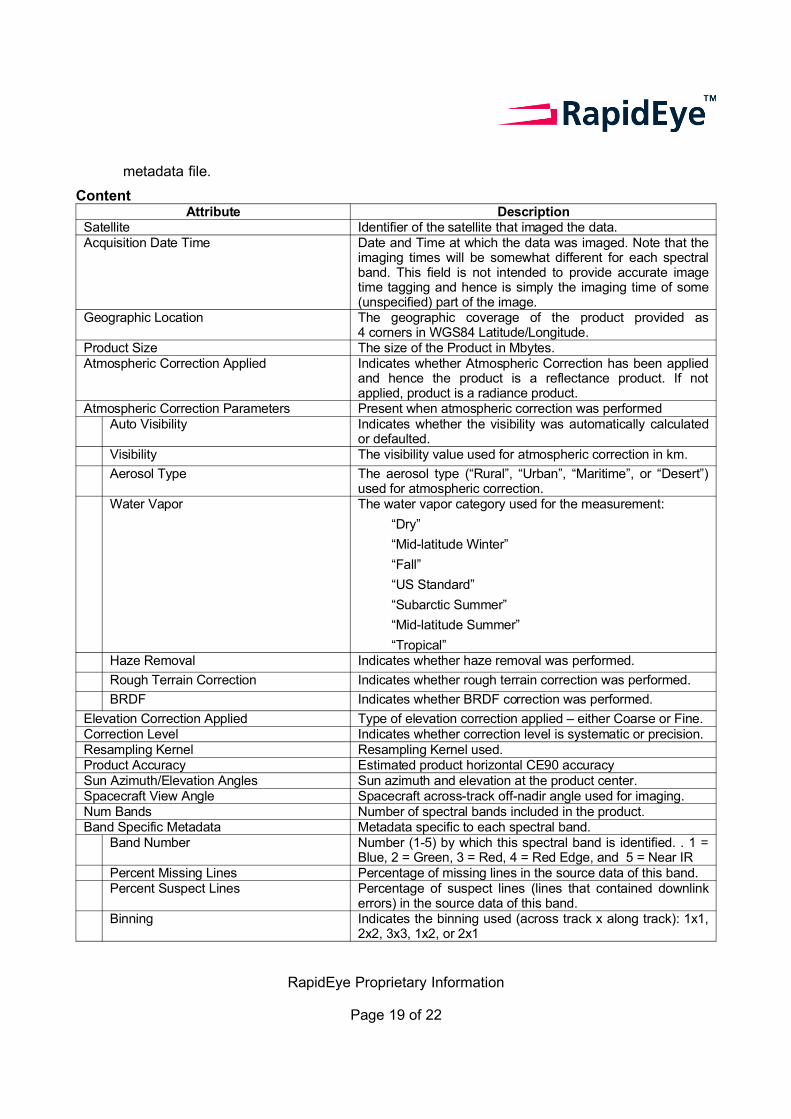
metadata file.
ContentAttribute Description
Satellite Identifier of the satellite that imaged the data.Acquisition Date Time Date and Time at which the data was imaged. Note that the
imaging times will be somewhat different for each spectral band. This field is not intended to provide accurate image time tagging and hence is simply the imaging time of some (unspecified) part of the image.
Geographic Location The geographic coverage of the product provided as 4 corners in WGS84 Latitude/Longitude.
Product Size The size of the Product in Mbytes.Atmospheric Correction Applied Indicates whether Atmospheric Correction has been applied
and hence the product is a reflectance product. If not applied, product is a radiance product.
Atmospheric Correction Parameters Present when atmospheric correction was performedAuto Visibility Indicates whether the visibility was automatically calculated
or defaulted.Visibility The visibility value used for atmospheric correction in km.
Aerosol Type The aerosol type (“Rural”, “Urban”, “Maritime”, or “Desert”) used for atmospheric correction.
Water Vapor The water vapor category used for the measurement:
“Dry”
“Mid-latitude Winter”
“Fall”
“US Standard”
“Subarctic Summer”
“Mid-latitude Summer”
“Tropical” Haze Removal Indicates whether haze removal was performed.
Rough Terrain Correction Indicates whether rough terrain correction was performed.
BRDF Indicates whether BRDF correction was performed.
Elevation Correction Applied Type of elevation correction applied – either Coarse or Fine.Correction Level Indicates whether correction level is systematic or precision.Resampling Kernel Resampling Kernel used.Product Accuracy Estimated product horizontal CE90 accuracySun Azimuth/Elevation Angles Sun azimuth and elevation at the product center.Spacecraft View Angle Spacecraft across-track off-nadir angle used for imaging.Num Bands Number of spectral bands included in the product.Band Specific Metadata Metadata specific to each spectral band.
Band Number Number (1-5) by which this spectral band is identified. . 1 = Blue, 2 = Green, 3 = Red, 4 = Red Edge, and 5 = Near IR
Percent Missing Lines Percentage of missing lines in the source data of this band.Percent Suspect Lines Percentage of suspect lines (lines that contained downlink
errors) in the source data of this band.Binning Indicates the binning used (across track x along track): 1x1,
2x2, 3x3, 1x2, or 2x1
RapidEye Proprietary Information
Page 19 of 22

Attribute DescriptionShifting Indicates the sensor applied right shifting: none, 1bit, 2bits,
3bits, or 4bits.Masking Indicates the sensor applied masking: 111, 110, 100, or 000.Radiometric Scale Factor Provides the parameter to convert the pixel value to radiance
(for radiance product) or reflectance (for a reflectance product). To convert to radiance/reflectance engineering units, the pixel values should be multiplied by this scale factor. Hence the pixel values in the product are:
Radiance product: (W/m2 sr µm) / (Radiometric Scale Factor). The Radiometric Scale Factor is expected to be 1/100. For instance, a product pixel value of 1510 would represent radiance units of 15.1 W/m2 sr µm.
Reflectance product: Percentage / (Radiometric Scale Factor). The Radiometric Scale Factor is expected to be 1/100. For instance, a product pixel value of 1510 would represent 15.1% reflectance.
FormatThe metadata will be formatted in XML.
File Naming ConventionThe metadata file will be named “<xxx..xx>__metadata.xml” where “<xxx..xx> is the identifier of the image generation request.
• Browse Image FileAll images regardless of processing level will have an accompanying browse image file.
ContentsThe browse image file contains a reduced-resolution representation of the product. It has the same aspect ratio and radiometric corrections as the product. The pixel/line spacing of the browse image will be roughly 48m. The file will contain 1 or 3 bands and pixels will be 8-bit. The 3-band browse image contains the Red, Green, and Blue bands. The 1 band browse image will contain the first available band in the following list: Red, Red Edge, Green, Blue, NIR.
FormatThe browse image is a JFIF (JPEG) file.
File Naming ConventionThe browse image file will be named “<xxx..xx>__browse.jpg” where “<xxx..xx> is the identifier of the image generation request.
RapidEye Proprietary Information
Page 20 of 22
• Unusable Data Mask File
All images regardless of processing level will have an accompanying unusable data mask file.
ContentsThe unusable data mask file provides information on areas of unusable data within an image (i.e. cloud and non-imaged areas). The pixel/line spacing of this file will each be roughly 48m. Each 8-bit pixel identifies whether the corresponding part of the product contains useful imagery:
• Bit 0: Identifies whether the area contains blackfill in all bands (this area was not imaged by the spacecraft). A value of 1 indicates blackfill.
• Bit 1: Identifies whether the area is cloud covered. A value of 1 indicates cloud covered. Cloud detection is performed on a decimated version of the image (i.e. the browse image) and hence small clouds may be missed. Cloud areas are those that have pixel values in the assessed band (Red, NIR or Green) that are above a configurable threshold. This algorithm will:
• Assess snow as cloud;
• Assess cloud shadow as cloud free;
• Assess haze as cloud free.
• Bit 2: Identifies whether the area contains missing (lost during downlink) or suspect (contains downlink errors) data in the Blue band. A value of 1 indicates missing/suspect data. If the product does not include this band, the value is set to zero.
• Bit 3: Identifies whether the area contains missing (lost during downlink and hence blackfilled) or suspect (contains downlink errors) data in the Green band. A value of 1 indicates missing/suspect data. If the product does not include this band, the value is set to zero.
• Bit 4: Identifies whether the area contains missing (lost during downlink) or suspect (contains downlink errors) data in the Red band. A value of 1 indicates missing/suspect data. If the product does not include this band, the value is set to zero.
• Bit 5: Identifies whether the area contains missing (lost during downlink) or suspect (contains downlink errors) data in the Red Edge band. A value of 1 indicates missing/suspect data. If the product does not include this band, the value is set to zero.
• Bit 6: Identifies whether the area contains missing (lost during downlink) or suspect (contains downlink errors) data in the NIR band. A value of 1 indicates missing/suspect data. If the product does not include this band, the value is set to zero.
RapidEye Proprietary Information
Page 21 of 22
FormatThe unusable data mask file is in a GeoTIFF format file with run-length compression.
File Naming ConventionThe unusable data mask file will be named “<xxx..xx>__mask.tif” where “<xxx..xx> is the identifier of the image generation request.
RapidEye Proprietary Information
Page 22 of 22