Rapid One-Pot Preparation of Large Freestanding ...
16
Rapid One-Pot Preparation of Large Freestanding Nanoparticle Polymer Films Xu, Y., Konrad, M. P., Trotter, J. L., McCoy, C. P., & Bell, S. E. J. (2017). Rapid One-Pot Preparation of Large Freestanding Nanoparticle Polymer Films. Small, 13(2), [1602163]. https://doi.org/10.1002/smll.201602163 Published in: Small Document Version: Peer reviewed version Queen's University Belfast - Research Portal: Link to publication record in Queen's University Belfast Research Portal Publisher rights © 2016 WILEY-VCH Verlag GmbH & Co. KGaA, Weinheim This is the peer reviewed version of the following article:Y. Xu, M. P. Konrad, J. L. Trotter, C. P. McCoy, S. E. J. Bell, Small 2017, 13, which has been published in final form at http://onlinelibrary.wiley.com/wol1/doi/10.1002/smll.201602163/abstract. This article may be used for non-commercial purposes in accordance with Wiley Terms and Conditions for Self-Archiving. General rights Copyright for the publications made accessible via the Queen's University Belfast Research Portal is retained by the author(s) and / or other copyright owners and it is a condition of accessing these publications that users recognise and abide by the legal requirements associated with these rights. Take down policy The Research Portal is Queen's institutional repository that provides access to Queen's research output. Every effort has been made to ensure that content in the Research Portal does not infringe any person's rights, or applicable UK laws. If you discover content in the Research Portal that you believe breaches copyright or violates any law, please contact [email protected]. Download date:14. Dec. 2021
Transcript of Rapid One-Pot Preparation of Large Freestanding ...

Rapid One-Pot Preparation of Large Freestanding NanoparticlePolymer Films
Xu, Y., Konrad, M. P., Trotter, J. L., McCoy, C. P., & Bell, S. E. J. (2017). Rapid One-Pot Preparation of LargeFreestanding Nanoparticle Polymer Films. Small, 13(2), [1602163]. https://doi.org/10.1002/smll.201602163
Published in:Small
Document Version:Peer reviewed version
Queen's University Belfast - Research Portal:Link to publication record in Queen's University Belfast Research Portal
Publisher rights© 2016 WILEY-VCH Verlag GmbH & Co. KGaA, Weinheim This is the peer reviewed version of the following article:Y. Xu, M. P. Konrad, J.L. Trotter, C. P. McCoy, S. E. J. Bell, Small 2017, 13, which has been published in final form athttp://onlinelibrary.wiley.com/wol1/doi/10.1002/smll.201602163/abstract. This article may be used for non-commercial purposes inaccordance with Wiley Terms and Conditions for Self-Archiving.
General rightsCopyright for the publications made accessible via the Queen's University Belfast Research Portal is retained by the author(s) and / or othercopyright owners and it is a condition of accessing these publications that users recognise and abide by the legal requirements associatedwith these rights.
Take down policyThe Research Portal is Queen's institutional repository that provides access to Queen's research output. Every effort has been made toensure that content in the Research Portal does not infringe any person's rights, or applicable UK laws. If you discover content in theResearch Portal that you believe breaches copyright or violates any law, please contact [email protected].
Download date:14. Dec. 2021
1
DOI: 10.1002/((please add manuscript number)) Article type: Communication Rapid One-Pot Preparation of Large Freestanding Nanoparticle-Polymer Films Yikai Xu, Magdalena P. Konrad, Johann L. Trotter, Colin P. McCoy, Steven E. J. Bell* [*] Prof. Steven E. J. Bell School of Chemistry and Chemical Engineering, Queen’s University, Belfast, BT9 5AG, U.K E-mail: [email protected] Keywords: freestanding films, interfacial self-assembly, nanomaterials As a result of the quantum effects, nanoparticles (NPs) often exhibit novel properties that
differ enormously from that of their bulk materials.[1] Notably, NPs packed in 2-dimensional
(2-D) or 3-dimensional (3-D) arrays often possess unique electrical,[2, 3] optical,[4, 5] and
magnetic[6] properties that stem from both the properties of the individual particles and the
electron coupling between neighboring particles.[7, 8] 2-D NP arrays have been particularly
closely studied, most often as deposited layers sitting on planar solid supports which are either
adsorbed from solution or deposited as a colloidal suspension dried onto the surface.[9-12]
An elegant method of obtaining NP 2-D arrays is through spontaneous self-assembly at
liquid-liquid interfaces to form metal liquid-like films (MeLLFs). These are densely packed
monolayer metal NPs self-assembled at the interface between two immiscible liquids, which
can be obtained simply by shaking a non-water-miscible organic solvent with a portion of
aqueous metal colloid in the presence of a low concentration of a chemical compound (a
“promoter” or “modifier”) which promotes particle adsorption at the interface.[13-19] These
mobile arrays have the same characteristics as the best of the deposited NP films in that they
are densely-packed, electronically coupled monolayers of particles which can readily be
prepared on the cm2 scale at room temperature in minutes with no specialist equipment.
Although these MeLLFs have been known for many years they have not been widely
2
exploited because the particles are difficult to access since they sit between two liquid layers.
There have been some attempts to develop methods to transferring them from liquid phase
into freestanding films. Several research groups have shown that by drying MeLLFs over
holey substrates micrometer-sized freestanding arrays can be created.[20-22] To transform
MeLLFs into larger freestanding cm2 scale films, up to now the most effective approach was
to sinter the particles but this gave a final product which was too weak even to withstand
direct characterization under electron microscopy.[23] The alternative approach of in-situ
polymerization of monomers linked on the surface of NPs can transform MeLLFs into
freestanding films.[24] However, although these films are stronger than the sintered analogues,
the NPs are completely trapped within an isolating polymer layer which removes most of their
potential applications since it prevents both chemical interaction and physical contact with the
NPs.
Ideally, what is required is a method to convert the mobile interfacial particle arrays into
freestanding films which are strong enough for routine handling and device construction but
still retain the structure of the MeLLFs and leave the particles chemically and physically
accessible. This is much more challenging than simply encasing the particle arrays in
polymer. Here we report a general and ‘one pot’ method to achieve all these goals by growing
a supportive thin polymer film in-situ at the organic side of the MeLLF’s liquid/liquid
interface. This approach means that the particles are fixed onto the surface of the supporting
polymer films rather than sitting on top of them or being trapped within them, which is why
we have named them SENS (Surface-Exposed Nanoparticle Sheets).
3
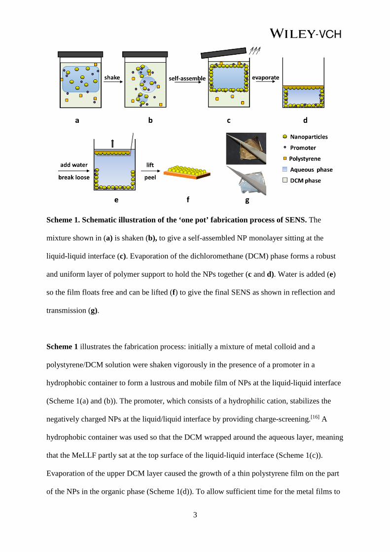
Scheme 1. Schematic illustration of the ‘one pot’ fabrication process of SENS. The
mixture shown in (a) is shaken (b), to give a self-assembled NP monolayer sitting at the
liquid-liquid interface (c). Evaporation of the dichloromethane (DCM) phase forms a robust
and uniform layer of polymer support to hold the NPs together (c and d). Water is added (e)
so the film floats free and can be lifted (f) to give the final SENS as shown in reflection and
transmission (g).
Scheme 1 illustrates the fabrication process: initially a mixture of metal colloid and a
polystyrene/DCM solution were shaken vigorously in the presence of a promoter in a
hydrophobic container to form a lustrous and mobile film of NPs at the liquid-liquid interface
(Scheme 1(a) and (b)). The promoter, which consists of a hydrophilic cation, stabilizes the
negatively charged NPs at the liquid/liquid interface by providing charge-screening.[16] A
hydrophobic container was used so that the DCM wrapped around the aqueous layer, meaning
that the MeLLF partly sat at the top surface of the liquid-liquid interface (Scheme 1(c)).
Evaporation of the upper DCM layer caused the growth of a thin polystyrene film on the part
of the NPs in the organic phase (Scheme 1(d)). To allow sufficient time for the metal films to
4
form at the interface before polymer deposition occurred, the rate of evaporation was
decreased by covering the container with an inverted beaker. This also increased the
uniformity of the resulting films over those prepared with an open vessel. After all the DCM
had evaporated the upper surface of the film was broken away from the rest with a scalpel and
floated to the top by adding excessive water. The film could then be lifted using a smooth flat
scoop slid horizontally under the film (Scheme 1(e)). During the lifting process the scoop
makes direct contact with the hydrophilic NPs so is best made from a hydrophobic material in
order to prevent sticking.
The optical properties of the SENS are very similar to those of the parent MeLLFs, in
particular the films retain their highly reflective metallic appearance (see Scheme 1g, Figure
S1(a) and (c) for Au, Figure S2 for Ag). In addition, when viewed in transmission the Au
films have the expected blue color (Figure S1(b)) as the parent MeLLFs. This color arises
from strong intraparticle coupling which can be observed in the UV/vis extinction spectra of
both the MeLLFs and SENS since it causes red-shifting and broadening of the unaggregated
gold colloid’s plasmon peak at ca. 525 nm.
The SENS were sufficiently robust to be handled with tweezers and were flexible enough to
be folded in half without snapping. Moreover, they were strong enough to withstand the 20
kV electron beam without damage during repeated scanning electron microscope (SEM)
measurements and focused laser illumination in SERS analysis (see below).
5
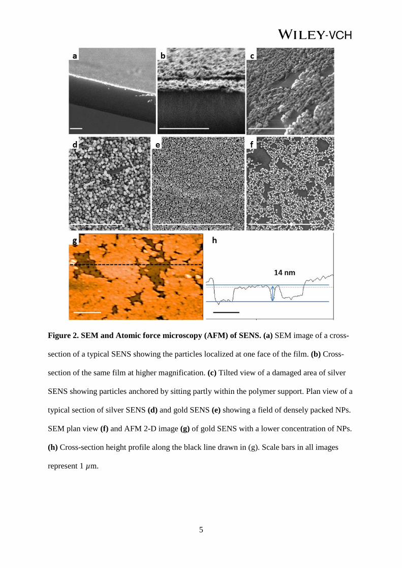
Figure 2. SEM and Atomic force microscopy (AFM) of SENS. (a) SEM image of a cross-
section of a typical SENS showing the particles localized at one face of the film. (b) Cross-
section of the same film at higher magnification. (c) Tilted view of a damaged area of silver
SENS showing particles anchored by sitting partly within the polymer support. Plan view of a
typical section of silver SENS (d) and gold SENS (e) showing a field of densely packed NPs.
SEM plan view (f) and AFM 2-D image (g) of gold SENS with a lower concentration of NPs.
(h) Cross-section height profile along the black line drawn in (g). Scale bars in all images
represent 1 µm.
6
Electron microscopy was used to characterize the microstructure of the SENS. Figure 2(a)
shows a cross-section of a typical SENS in which the polymer layer is ca. 2.5 µm thick. The
particles are localized at a single face, as illustrated in Scheme 1(g). Figure 2(b), which is a
higher magnification cross-section shows a monolayer of particles sitting at the top surface.
The particles within this layer have the expected structure of a densely-packed monolayer as
shown in the plan views (Figure 2 (d) and (e)). Figure 2(c) shows an image of a damaged area
near the edge of the SENS which gives a clearer view of how the bottom of each of the NPs
sit within the polymer support, anchoring them in place. This final structure is consistent with
the observation that the particles in the SENS carry a citrate/and or chloride surface layer
which makes them hydrophilic, so they will sit predominantly at the aqueous side of the
liquid-liquid interface while the polymer is deposited from the organic side of the interface.
Figure 2(f) show a gold SENS with a lower concentration of NPs ca. 25 nm in diameter to
reveal the polymer backing. By conducting AFM topography measurements of the film it was
shown that the monolayer of NPs were ca. half-way embedded into the polymer suggesting
that the NPs had a near 90 ° contact angle at the interface (Figure 2(g) and (h)). This is
consistent with the calculated profile of self-assembled NP monolayers at liquid-liquid
interfaces. [17, 25]
Of course neither high magnification SEM or AFM would be able to detect if there was a thin
(< 2 nm) layer of polymer covering the particles and such a problem is a real possibility.
However, this can be tested using contact angle measurements and direct chemical reactivity
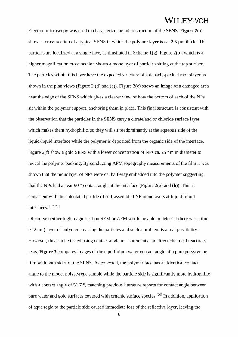
tests. Figure 3 compares images of the equilibrium water contact angle of a pure polystyrene
film with both sides of the SENS. As expected, the polymer face has an identical contact
angle to the model polystyrene sample while the particle side is significantly more hydrophilic
with a contact angle of 51.7 °, matching previous literature reports for contact angle between
pure water and gold surfaces covered with organic surface species.[26] In addition, application
of aqua regia to the particle side caused immediate loss of the reflective layer, leaving the
7
transparent polystyrene film (Figure S3). Conversely, application of the same acid to the
polymer side had no effect on the films.
Figure 3. Contact angle measurements and acid droplet experiment. Contact angle
between a pure polystyrene film and water (a), the polystyrene side of gold SENS and water
(b), the NP side of gold SENS and water (c). (d) Optical image of a gold SENS holding a
droplet of aqua regia on its polymer side.
All the observations above combine to confirm that the NPs are indeed only partly submerged
into polymer, which holds them in place while still leaving the majority of their surfaces
exposed. This is in sharp contrast with previous cases where the NPs were completely trapped
inside polymer.[24] Conversely, the particle films are also different from materials where the
particles sit on top of a substrate because here the particles are firmly fixed to the polymer
backing, which makes them much more mechanically robust. In attempts to measure the
scratch hardness of the films using the ASTM Pencil Test we found that with pencils harder
than 5B the tips gouged the polystyrene films before any particle shedding was observed.[27]
Similarly, the films can be submerged in agitated water for > 12 hours without any noticeable
loss of particles.
8
The method is very general since SENS with different nanoparticles/supporting polymer can
readily be prepared by changing the starting materials. Examples of SENS prepared with
different metals and polymers (gold and silver on polystyrene and poly (methyl
methacrylate)) are shown in Figure S4. Similarly, the film thickness can be changed by
altering the amount of polymer added. In this work the films were typically prepared with
0.05- 0.08 g/mL of polystyrene in DCM to give ca. 2 µm films but concentrations from 0.02
to 0.12 g/mL were tested and gave films ranging from 0.5 – 10 µm. The size of the films can
easily be changed by altering the size of the interfacial area. For convenience the films
discussed above were typically prepared in 60 mm diameter containers which gave ca. 60 mm
diameter circular SENS that could be cut to different sizes as required. However, the process
is scalable so for illustration a sample with diameter of 150 mm was prepared and lifted out of
the liquid after it was broken away from the sides of the container by adding water following
the protocol shown in Scheme 1e (Figure. 4a). Even in this simple laboratory demonstration,
a ca. 170 cm2 SENS could be produced.
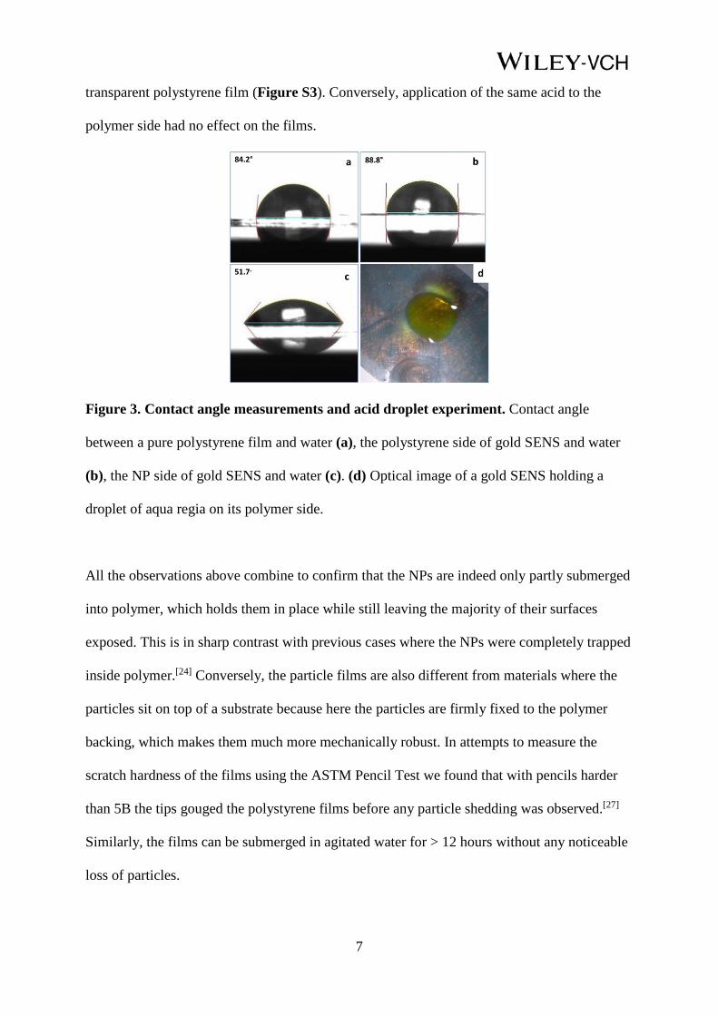
Figure 4. Large scale fabrication of SENS and examples of applications. (a) Photograph
of a silver SENS in-situ (top image). The scale bar on the picture represents 7 cm. The bottom
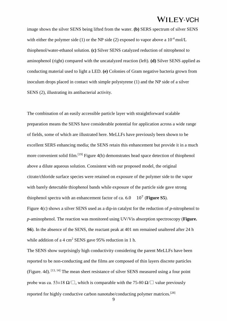
9
image shows the silver SENS being lifted from the water. (b) SERS spectrum of silver SENS
with either the polymer side (1) or the NP side (2) exposed to vapor above a 10-4 mol/L
thiophenol/water-ethanol solution. (c) Silver SENS catalyzed reduction of nitrophenol to
aminophenol (right) compared with the uncatalyzed reaction (left). (d) Silver SENS applied as
conducting material used to light a LED. (e) Colonies of Gram negative bacteria grown from
inoculum drops placed in contact with simple polystyrene (1) and the NP side of a silver
SENS (2), illustrating its antibacterial activity.
The combination of an easily accessible particle layer with straightforward scalable
preparation means the SENS have considerable potential for application across a wide range
of fields, some of which are illustrated here. MeLLFs have previously been shown to be
excellent SERS enhancing media; the SENS retain this enhancement but provide it in a much
more convenient solid film.[19] Figure 4(b) demonstrates head space detection of thiophenol
above a dilute aqueous solution. Consistent with our proposed model, the original
citrate/chloride surface species were retained on exposure of the polymer side to the vapor
with barely detectable thiophenol bands while exposure of the particle side gave strong
thiophenol spectra with an enhancement factor of ca. 6.0 × 10⁷ (Figure S5).
Figure 4(c) shows a silver SENS used as a dip-in catalyst for the reduction of p-nitrophenol to
p-aminophenol. The reaction was monitored using UV/Vis absorption spectroscopy (Figure.
S6). In the absence of the SENS, the reactant peak at 401 nm remained unaltered after 24 h
while addition of a 4 cm2 SENS gave 95% reduction in 1 h.
The SENS show surprisingly high conductivity considering the parent MeLLFs have been
reported to be non-conducting and the films are composed of thin layers discrete particles
(Figure. 4d). [13, 14] The mean sheet resistance of silver SENS measured using a four point
probe was ca. 53±18 Ω/, which is comparable with the 75-80 Ω/ value previously
reported for highly conductive carbon nanotube/conducting polymer matrices.[28]
10
The silver particle sides of SENS show significant microbicidal activity. 20 µL droplets
containing 107 cfu/mL gram-negative or gram-positive bacteria were placed onto the particle
side of the SENS or the plain polystyrene control material. After 4 hours the SENS samples
showed a 1 log reduction in CFU for the gram-positive and 2 log reduction for the gram-
negative bacteria (Figure. 4e.)
The ability to prepare SENS with a wide range of components allows them to be optimized
for each application. For example, the rate of nitrophenol reduction was significantly higher
with silver SENS than gold SENS prepared with 10 ±1 nm gold NPs and much higher than
that observed with large gold particles. Conversely gold SENS prepared with 35 ±10 nm
irregularly shaped NPs had significantly higher conductivity than SENS prepared with
spherical 10 ±1 nm gold NPs.
In summary, we have designed a surprisingly simple “bottom-up” method to prepare highly-
organized nanostructured materials which combine the advantages of both the exposed films
formed by solvent evaporation onto solid supports and freestanding flexible NP-embedded
polymer matrices. The combination of room temperature self-assembly of NPs with solvent
evaporation induced polymer growth gives this one-pot method scalability, simplicity and
cost-efficiency vastly superior to previous methods of fabricating freestanding NP films.
Since the SENS are planar 2-D assemblies of NPs they can be readily used for the
applications already proposed for 2-D NP arrays such as sensors, plasmonic displays, dip-in
catalysts etc. but at dramatically reduced cost. It has been shown that many interesting
materials can be assembled at the liquid-liquid interface. However, an effective way to extract
them for further characterization and applications is still lacking.[29, 30] Here our method
provides a potentials way to achieve this and in addition the active components in SENS can
be post-processed because the particles remain accessible. This means that SENS can provide
a general approach to creating generic components for a wide range of more complex
engineered nanodevices.
11
Experimental Section
Materials: Silver nitrate (99.9999%), gold (III) chloride hydrate (99.9999%), trisodium
citrate, tetrabutylammonium nitrate, p-nitrophenol, sodium borohydride, nitric acid (≥65%),
thiophenol, DCM, poly (methyl methacrylate) (M. W. 15000), conductive copper tape and
screw-cap polypropylene centrifuge tubes were purchased from Aldrich Ltd. Polystyrene (M.
W. approximately 100000) was purchased from BDH chemicals Ltd. The chemicals were
used without further purification. Water used throughout all experiments was low TOC (<3.0
ppb) 18.2 MΩcm water. For antibacterial tests, Pseudomonas aeruginosa PA01 and
Staphylococcus aureus ATCC 6538 were obtained from LGC Standards, Middlesex, UK.
Mueller-Hinton agar plates, phosphate-buffered saline, tryptone soya broth and quarter-
strength Ringers solution were obtained from Oxoid Ltd, Basingstoke, UK.
Instrumentation: Extinction spectra were measured on an Agilent 8453 photodiode array UV-
vis spectrophotometer in 1 cm quartz cuvettes with water or DCM references used as
appropriate. SENS were referenced against air. Reduction of p-nitrophenol was monitored at
room temperature (ca. 20 ºC). ca. 4 cm2 SENS were used for all catalyzed reactions. Raman
spectra of SENS were collected using a Perkin Elmer RamanMicro 200 Raman Microscope
equipped with a 785 nm diode laser. In a typical contrast experiment, SERS spectrum of
SENS were collected with either side of SENS exposed to 1.5 mL of 10-4 mol/L
thiophenol/water-ethanol solution in an enclosed 35 mL bottle overnight. The two pieces of
SENS were fixed to a piece of standard adhesive SEM copper tape each with a different side
facing up to ensure that the thiophenol vapor could not reach the other side of the film. All
spectra were further processed using Grams software. Contact angle measurements were
performed with a FTA 1000 Analyze System on 1 cm2 SENS. Low magnification optical
images were recorded with an Olympus BX60 microscope fitted with an Olympus digital
camera. For acid-treatment, a drop of concentrated nitric acid was added onto either side of a

12
silver SENS (aqua regia for gold SENS) with a gas chromatography syringe and observed
through the optical microscope. Conventional optical images were taken with a Nikon
COOLPIX L820. SEM used a Quanta FEG 250 at an acceleration voltage of 20 kV under
high chamber pressure (8×10⁻⁵ mbar) with standard SEM copper tape or carbon tape as
background. AFM was conducted using a Nanosurf Flex AFM in dynamic force mode.
Pencil test for film hardness was conducted following standard protocols.[24] Conductivity
measurements were performed with the homemade four point probe system shown in Figure.
S7.
Procedure for SENS fabrication: Citrate-reduced silver and gold colloids were prepared via
the Lee and Meisel and Turkevich-Frens methods. [31, 32] Hydroxylamine reduced silver
colloid was prepared via Leopold’s method. [33] SENS were normally prepared by vigorously
shaking 5 mL of aqueous NP colloid with 3 mL of polystyrene/DCM (0.05 g/mL) solution
and 1.2 mL of aqueous tetrabutylammnonium nitrate (10-4 mol/L) for 30 seconds. The
agitated mixture was poured immediately into a polypropylene petri dish and covered with an
inverted beaker. A lustrous metallic film spontaneously formed at the interface when particle-
covered bubbles of DCM merged, this process took less than 1 minute. Typically, the mixture
was left in air to allow all the DCM to evaporate, which created a robust polymer film with a
metallic appearance at the water/air interface. The film was then separated from the walls of
the petri dish with a scalpel and excess water added to float the top layer free. A piece of stiff
paper was then carefully slid beneath the film to lift it from water. The film was dried in air
and then peeled off from the lifting material. To reduce the evaporation time to ca. 30 minutes
the beaker could be removed after the self-assembly process was complete. Larger films could
be prepared by using larger volumes of the reagents in the same ratio. The large film shown in
this paper was 150 mm in diameter and prepared with 300 mL of CRSC in a domestic
polypropylene bowl.
13
Antibacterial Testing: 1 ×1 cm2 sections of SENS were mounted on a rigid backing material
and droplets of inoculum containing 107 cfu/mL were deposited on the silver particle side, left
in place for 4 hours and then removed, plated out and counted, as shown in Method S1.
Supporting Information Supporting Information is available from the Wiley Online Library or from the author. Acknowledgements The author would like to thank Prof. A. P. de Silva and Prof. A. Mills for their invaluable suggestions on improving the manuscript.
Received: ((will be filled in by the editorial staff)) Revised: ((will be filled in by the editorial staff))
Published online: ((will be filled in by the editorial staff))
[1] E. Roduner, Nanoscopic Materials Size-Dependent Phenomena (RSC Publishing,
London 2006, Ch.1).
[2] M. -P. Pileni, Acc. Chem. Res. 2007, 40, 685.
[3] A. Zabet-Khosousi, A. -A. Dhirani, Chem. Rev. 2008, 108, 4072.
[4] A. G. Dong, J. Chen, P. M. Vora, J. M. Kikkawa, C. B. Murray, Nature 2010, 466, 474.
[5] A. G. Dong, X. C. Ye, J. Chen, C. B. Murray, Nano Lett. 2011, 11, 1804.
[6] S. H. Sun, C. B. Murray, D. Weller, L. Folks, A. Moser, Science 2000, 287, 1989.
[7] E. Prodan, C. Radloff, N. J. Halas, P. Nordlander, Science 2003, 302, 419.
[8] M. P. Pileni, Appl. Surf. Sci. 2001, 171, 1.
[9] C. J. Kiely, J. Fink, M. Brust, D. Bethell, D. J. Schiffrin, Nature 1993, 396, 444.
[10] H. -X. Lin, L. Chen, D. -Y. Liu, Z. -C. Lei, Y. Wang, X. -S. Zheng, B. Ren, Z. -X. Xie,
G. D. Stucky, Z. -Q. Tian, J. Am. Chem. Soc. 2015, 137, 2828.
[11] C. E. McCold, Q. Fu, J. Y. Howe, J. Hihath, Nanoscale 2015, 7, 14937.
[12] J. Liao, L. Bernard, M. Langer, C. Schönenberger, M. Calame, Adv. Mater. 2006, 18,
2444.
14
[13] K. C. Gordon, J. J. McGarvey, K. P. Taylor, J. Phys. Chem. 1989, 93, 6814.
[14] D. Yogev, S. Efrima, J. Phys. Chem. 1988, 92, 5754.
[15] H. Duan, D. Wang, D. G. Kurth, H. Möhwald, Angew. Chem. Int. Ed. 2004, 43, 5639.
[16] Y. Xu, M. P. Konrad, W. W. Y. Lee, Z. Ye, S. E. J. Bell, Nano Lett. 2016, 16, 5255.
[17] F. Reincke, S. G. Hickey, W. K. Kegel, D. Vanmaekelbergh, Angew. Chem., Int. Ed.
2004, 43, 458.
[18] C. N. R. Rao, K. P. Kalyanikutty, Acc. Chem. Res. 2008, 41, 489.
[19] M. P. Konrad, A. P. Doherty, S. E. J. Bell, Anal. Chem. 2013, 85, 6783.
[20] K. E. Mueggenburg, X. -M. Lin, R. H. Goldsmith, H. M. Jaeger, Nature Mat. 2007, 6,
656.
[21] W. Cheng, M. J. Campolongo, J. J. Cha, S. J. Tan, C. C. Umbach, D. A. Muller, D. Luo.
Nature Mat. 2009, 8, 519.
[22] J. Liao, Y. Zhou, C. Huang, Y. Wang, L. Peng, Small, 2011, 5, 583.
[23] H. Xia, D. Y. Wang, Adv. Mater. 2008, 20, 4253.
[24] Y. Chen, J. Fu, K. C. Ng, Y. Tang, W. Cheng, Cryst. Growth Des. 2011, 11, 4742.
[25] B. P. Binks, Curr. Opin. in Colloid Interface Sci. 2002,7, 21.
[26] K. W. Bewig, W. A. Zisman, J. Phys. Chem. 1964, 68, 1804.
[27] ASTM D3363-00 “Standard Test Method for Film Hardness by Pencil Test1,” ASTM
International, West Conshohoken, PA (2011)
[28] S. De, P. E. Lyons, S. Sorel, E. M. Doherty, P. J. King, W. J. Blau, P. N. Nirmalraj, J. J.
Boland, V. Scardaci, J. Joimel, J. N. Coleman, ACS Nano 2009, 3. 714.
[29] S. G. Booth, R. A. W. Dryfe, J. Phys. Chem. C, 2015, 119, 23295.
[30] Y. Liu, Z. Wu, H. Zhang, Adv. Colloid and Interface Sci. 2014, 207, 347.
[31] P. C. Lee, D. Meisel, J. Phys. Chem. 1982, 86, 3391.
[32] G. Frens, Nature-Phys Sci. 1973, 241, 20.

15
[33] N. Leopold, M. Haberkorn, T. Laurell, J. Nilsson, J. R. Baena, J. Frank, B. Lendl,
Anal. Chem. 2003, 75, 2166.